JP5415564B2 - Human body posture and motion determination system using optical signal, and human body posture and motion determination method - Google Patents
Human body posture and motion determination system using optical signal, and human body posture and motion determination methodDownload PDFInfo
- Publication number
- JP5415564B2 JP5415564B2JP2011549053AJP2011549053AJP5415564B2JP 5415564 B2JP5415564 B2JP 5415564B2JP 2011549053 AJP2011549053 AJP 2011549053AJP 2011549053 AJP2011549053 AJP 2011549053AJP 5415564 B2JP5415564 B2JP 5415564B2
- Authority
- JP
- Japan
- Prior art keywords
- optical signal
- human body
- transmission path
- signal transmission
- optical
- Prior art date
- Legal status (The legal status is an assumption and is not a legal conclusion. Google has not performed a legal analysis and makes no representation as to the accuracy of the status listed.)
- Expired - Fee Related
Links
- 230000003287optical effectEffects0.000titleclaimsdescription187
- 230000033001locomotionEffects0.000titleclaimsdescription69
- 238000000034methodMethods0.000titleclaimsdescription38
- 230000008054signal transmissionEffects0.000claimsdescription106
- 230000005540biological transmissionEffects0.000claimsdescription43
- 230000008859changeEffects0.000claimsdescription36
- 239000013307optical fiberSubstances0.000claimsdescription22
- 238000004458analytical methodMethods0.000claimsdescription20
- 238000012545processingMethods0.000claimsdescription19
- 238000004891communicationMethods0.000description8
- 238000010586diagramMethods0.000description8
- 230000008569processEffects0.000description6
- 239000003550markerSubstances0.000description3
- 230000008901benefitEffects0.000description2
- 238000004364calculation methodMethods0.000description2
- 238000004590computer programMethods0.000description2
- 230000000694effectsEffects0.000description2
- 230000007246mechanismEffects0.000description2
- 230000000737periodic effectEffects0.000description2
- 238000005070samplingMethods0.000description2
- 238000013459approachMethods0.000description1
- 244000309466calfSpecies0.000description1
- 238000013500data storageMethods0.000description1
- 230000007423decreaseEffects0.000description1
- 238000005516engineering processMethods0.000description1
- 230000007274generation of a signal involved in cell-cell signalingEffects0.000description1
- 231100001261hazardousToxicity0.000description1
- 239000000463materialSubstances0.000description1
- 238000012986modificationMethods0.000description1
- 230000004048modificationEffects0.000description1
- 230000002093peripheral effectEffects0.000description1
- 230000004044responseEffects0.000description1
Images


Classifications
- A—HUMAN NECESSITIES
- A61—MEDICAL OR VETERINARY SCIENCE; HYGIENE
- A61B—DIAGNOSIS; SURGERY; IDENTIFICATION
- A61B5/00—Measuring for diagnostic purposes; Identification of persons
- A61B5/02—Detecting, measuring or recording for evaluating the cardiovascular system, e.g. pulse, heart rate, blood pressure or blood flow
- A61B5/024—Measuring pulse rate or heart rate
- A61B5/02416—Measuring pulse rate or heart rate using photoplethysmograph signals, e.g. generated by infrared radiation
- A—HUMAN NECESSITIES
- A61—MEDICAL OR VETERINARY SCIENCE; HYGIENE
- A61B—DIAGNOSIS; SURGERY; IDENTIFICATION
- A61B5/00—Measuring for diagnostic purposes; Identification of persons
- A61B5/103—Measuring devices for testing the shape, pattern, colour, size or movement of the body or parts thereof, for diagnostic purposes
- A61B5/11—Measuring movement of the entire body or parts thereof, e.g. head or hand tremor or mobility of a limb
- A61B5/1116—Determining posture transitions
- A—HUMAN NECESSITIES
- A61—MEDICAL OR VETERINARY SCIENCE; HYGIENE
- A61B—DIAGNOSIS; SURGERY; IDENTIFICATION
- A61B5/00—Measuring for diagnostic purposes; Identification of persons
- A61B5/103—Measuring devices for testing the shape, pattern, colour, size or movement of the body or parts thereof, for diagnostic purposes
- A61B5/11—Measuring movement of the entire body or parts thereof, e.g. head or hand tremor or mobility of a limb
- A61B5/1123—Discriminating type of movement, e.g. walking or running
- A—HUMAN NECESSITIES
- A61—MEDICAL OR VETERINARY SCIENCE; HYGIENE
- A61B—DIAGNOSIS; SURGERY; IDENTIFICATION
- A61B5/00—Measuring for diagnostic purposes; Identification of persons
- A61B5/145—Measuring characteristics of blood in vivo, e.g. gas concentration or pH-value ; Measuring characteristics of body fluids or tissues, e.g. interstitial fluid or cerebral tissue
- A61B5/1455—Measuring characteristics of blood in vivo, e.g. gas concentration or pH-value ; Measuring characteristics of body fluids or tissues, e.g. interstitial fluid or cerebral tissue using optical sensors, e.g. spectral photometrical oximeters
- G—PHYSICS
- G08—SIGNALLING
- G08B—SIGNALLING OR CALLING SYSTEMS; ORDER TELEGRAPHS; ALARM SYSTEMS
- G08B21/00—Alarms responsive to a single specified undesired or abnormal condition and not otherwise provided for
- G08B21/02—Alarms for ensuring the safety of persons
- A—HUMAN NECESSITIES
- A61—MEDICAL OR VETERINARY SCIENCE; HYGIENE
- A61B—DIAGNOSIS; SURGERY; IDENTIFICATION
- A61B2562/00—Details of sensors; Constructional details of sensor housings or probes; Accessories for sensors
- A61B2562/02—Details of sensors specially adapted for in-vivo measurements
- A61B2562/0261—Strain gauges
- A61B2562/0266—Optical strain gauges
- A—HUMAN NECESSITIES
- A61—MEDICAL OR VETERINARY SCIENCE; HYGIENE
- A61B—DIAGNOSIS; SURGERY; IDENTIFICATION
- A61B5/00—Measuring for diagnostic purposes; Identification of persons
- A61B5/68—Arrangements of detecting, measuring or recording means, e.g. sensors, in relation to patient
- A61B5/6801—Arrangements of detecting, measuring or recording means, e.g. sensors, in relation to patient specially adapted to be attached to or worn on the body surface
- A61B5/6802—Sensor mounted on worn items
- A61B5/6804—Garments; Clothes
- A61B5/6805—Vests, e.g. shirts or gowns
- A—HUMAN NECESSITIES
- A61—MEDICAL OR VETERINARY SCIENCE; HYGIENE
- A61B—DIAGNOSIS; SURGERY; IDENTIFICATION
- A61B5/00—Measuring for diagnostic purposes; Identification of persons
- A61B5/68—Arrangements of detecting, measuring or recording means, e.g. sensors, in relation to patient
- A61B5/6801—Arrangements of detecting, measuring or recording means, e.g. sensors, in relation to patient specially adapted to be attached to or worn on the body surface
- A61B5/683—Means for maintaining contact with the body
- A61B5/6831—Straps, bands or harnesses
Landscapes
- Health & Medical Sciences (AREA)
- Life Sciences & Earth Sciences (AREA)
- Physics & Mathematics (AREA)
- Molecular Biology (AREA)
- Animal Behavior & Ethology (AREA)
- Veterinary Medicine (AREA)
- Biophysics (AREA)
- Pathology (AREA)
- Engineering & Computer Science (AREA)
- Biomedical Technology (AREA)
- Heart & Thoracic Surgery (AREA)
- Medical Informatics (AREA)
- Public Health (AREA)
- Surgery (AREA)
- General Health & Medical Sciences (AREA)
- Oral & Maxillofacial Surgery (AREA)
- Dentistry (AREA)
- Physiology (AREA)
- Cardiology (AREA)
- Spectroscopy & Molecular Physics (AREA)
- Optics & Photonics (AREA)
- Business, Economics & Management (AREA)
- Emergency Management (AREA)
- General Physics & Mathematics (AREA)
- Arrangements For Transmission Of Measured Signals (AREA)
- Measurement Of The Respiration, Hearing Ability, Form, And Blood Characteristics Of Living Organisms (AREA)
- Investigating Or Analysing Materials By Optical Means (AREA)
Description
Translated fromJapanese本発明は、人体状態判定技術に係り、より詳しくは、人体の少なくとも1部位の状態変化、人体の姿勢、および人体の運動状態を判定することができる、光信号を用いた人体の姿勢および動作判定システムおよび人体の姿勢および動作判定方法に関する。The present invention relates to a human body state determination technique, and more particularly, a human bodyposture and motion using an optical signal that can determine a state change of at least one part of the human body, a human body posture, and a human body motion state. The present invention relates to a determination system and a human bodyposture and motion determination method.
人体の姿勢および動作を判定する、いわゆるモーションディテクティング(motion detecting)技術には、多数のマーカを用いてセンシングされる人体信号に基づいて人体の姿勢および動作を判定する技術や、多数のカメラを用いて人体の動きを撮影して人体の姿勢および動作を判定する技術などがある。Determining the bodyposture and behavior, the so-called Motion Tech Computing (motion Detecting) technologies, techniques and determines the bodyposture and operation based on the human body signal is sensed using a number of markers, a number of camera There is a technique for determining theposture and movement of a human body by photographing the movement of the human body.
マーカを用いた技術は、皮膚にマーカを直接付けなければならない不便さがあり、単に人体の動きのみを判定することができ、人体部位に力が入っている度合いを判定することができず、人体部位の3次元的変化を判定することができないという欠点を持つ。カメラを用いた技術は、まず、高価のカメラを用いるため費用が高く、マーカを用いた技術と同様に人体部位の3次元的変化を判定することができない欠点をもつ。また、上述した2つの技術は両方とも、産業現場に適用され難いうえ、火災現場や救急状況などの急迫した危険環境にはさらに適用され難い。 The technique using the marker has the inconvenience of having to put the marker directly on the skin, can only determine the movement of the human body, cannot determine the degree of force in the human body part, There is a drawback that it is impossible to determine a three-dimensional change of a human body part. First, the technique using a camera is expensive because an expensive camera is used, and has the disadvantage that it is impossible to determine a three-dimensional change in a human body part as in the technique using a marker. In addition, both of the above-described two techniques are difficult to apply to industrial sites, and more difficult to apply to urgent dangerous environments such as fire sites and emergency situations.
そこで、本発明の技術的課題は、人体の少なくとも1部位に装着され、前記人体の少なくとも1部位の状態変化、人体の姿勢、および人体の運動状態を簡単かつ迅速に判定することができ、ひいては産業現場または危険環境においても適用することができる、人体の姿勢および動作判定システムおよび人体の姿勢および動作判定方法を提供することにある。Therefore, the technical problem of the present invention is that it is attached to at least one part of the human body and can easily and quickly determine the state change of the at least one part of the human body, the posture of the human body, and the movement state of the human body. An object of the present invention is to provide a human bodyposture and motion determination system and a human bodyposture and motion determination method that can be applied in an industrial field or a hazardous environment.
上記技術的課題を解決するための、光信号を用いた人体の姿勢および動作判定システムは、光信号送信モジュール、光信号伝達モジュール、および人体状態分析モジュールを含むことができる。前記光信号送信モジュールは、光信号を発生して出力することができる。前記光信号伝達モジュールは、人体のいずれか1部位に装着可能であり、少なくとも一つの切断端部を有する少なくとも一つの光信号伝達経路を備えることができる。前記人体状態分析モジュールは、前記少なくとも一つの光信号伝達経路の前記少なくとも一つの切断端部の間隔に基づいて変化する前記少なくとも一つの光信号伝達経路の光伝達比率を算出し、人体のいずれか1部位の状態変化を判定することができる。この際、前記少なくとも一つの光信号伝達経路の前記いずれか一つの切断端部の間隔は、前記人体のいずれか1部位の周長の変化に基づいて変化させることができる。A human bodyposture and motion determination system using an optical signal for solving the above technical problem may include an optical signal transmission module, an optical signal transmission module, and a human body state analysis module. The optical signal transmission module can generate and output an optical signal. The optical signal transmission module can be attached to any one part of the human body, and can include at least one optical signal transmission path having at least one cut end. The body state analysis module, the calculated at least one light transmission ratio of the at least one optical signal transmission path the changes based on the distance of the at least one cut end of the optical signal transmission path,either humanA change inthe state ofone site can be determined. At this time, the interval between the cut ends of the at least one optical signal transmission path can be changed based on the change in the circumference of any one part of the human body.
前記人体の姿勢および動作判定システムは、互いに分離された人体の姿勢および動作判定用センシング装置および人体の姿勢および動作判定装置により実現される。前記人体の姿勢および動作判定用センシング装置は、光信号を発生して出力する光信号送信モジュール、人体の1部位に装着可能であり、少なくとも一つの切断端部を有する少なくとも一つの光信号伝達経路を備える光信号伝達モジュール、および前記光信号伝達モジュールから出力される光信号に基づいて発生するデータを外部へ伝送するデータ伝送モジュールを含むことができる。この際、前記少なくとも一つの光信号伝達経路の前記いずれか一つの切断端部の間隔は、前記人体のいずれか1部位の周長の変化に基づいて変化させることができる。The human bodyposture and motion determination system is realized by a human bodyposture and motion determination sensing device and a human bodyposture and motion determination device separated from each other. The sensing apparatus forposture and motion determination of the human body generates an optical signal and outputs an optical signal transmission module, which can be attached to one part of the human body, and has at least one optical signal transmission path having at least one cut end And a data transmission module for transmitting data generated based on an optical signal output from the optical signal transmission module to the outside. At this time, the interval between the cut ends of the at least one optical signal transmission path can be changed based on the change in the circumference of any one part of the human body.
前記人体の姿勢および動作判定装置は、前記人体の姿勢および動作判定用センシング装置から受信される加工データに基づいて人体の姿勢および動作を判定することができる。前記人体の姿勢および動作判定装置は、前記人体の姿勢および動作判定用センシング装置から前記加工データを受信する受信モジュール、および前記受信された加工データに基づいて前記少なくとも一つの光信号伝達経路の光伝達比率を算出し、前記算出された光伝達比率に基づいて人体のいずれか1部位の状態変化を判定する演算モジュールを含むことができる。The bodyposture and motion determination device may determine the bodyposture and operation based on the processing data received from the human bodyposture and operation determination sensing apparatus. The human bodyposture and motion determination device includes: a receiving module that receives the processing data from the human bodyposture and motion determination sensing device; and a light of the at least one optical signal transmission path based on the received processing data.An arithmetic module that calculates atransmission ratio and determinesa state change ofany one part of the human body based on the calculated lighttransmission ratio can be included.
前記技術的課題を解決するための人体の姿勢および動作判定方法は、光信号を発生して出力する段階と、人体の1部位に装着可能であり、少なくとも一つの切断端部を有する少なくとも一つの光信号伝達経路を用いて光信号を伝達する段階と、前記少なくとも一つの光信号伝達経路の前記少なくとも一つの切断端部の間隔に基づいて変化する前記少なくとも一つの光信号伝達経路の光伝達比率に基づいて人体のいずれか1部位の状態変化を判定する段階とを含むことができる。この際、前記少なくとも一つの光信号伝達経路の前記いずれか一つの切断端部の間隔は、前記人体のいずれか1部位の周長の変化に基づいて変化させることができる。The method for determiningthe posture and movement of a human body for solving the technical problem includes a step of generating and outputting an optical signal, and at least one cutting edge that can be attached to one part of the human body. Transmitting an optical signal using an optical signal transmission path, and an optical transmission ratio of the at least one optical signal transmission path that changes based on an interval between the at least one cut end of the at least one optical signal transmission path And determiningthe state change ofany one part of the human body based on the above. At this time, the interval between the cut ends of the at least one optical signal transmission path can be changed based on the change in the circumference of any one part of the human body.
本発明の実施形態に係る人体の姿勢および動作判定方法は、コンピュータが読み取り可能な記録媒体に格納された、前記人体の姿勢および動作判定方法を実行するためのコンピュータプログラムを実行することにより実現される。A human bodyposture and motion determination method according to an embodiment of the present invention is realized by executing a computer program stored in a computer-readable recording medium for executing the human bodyposture and motion determination method. The
上述したように、本発明に係る光信号を用いた人体の姿勢および動作判定システムおよび人体の姿勢および動作判定方法は、従来の技術に比べて人体の一部分の状態、人体の姿勢、および人体の運動状態を簡単かつ迅速に判定することができるという効果がある。また、無線通信ネットワークを用いる場合、本発明に係る人体の姿勢および動作判定システムおよび人体の姿勢および動作判定方法は、遠距離からも人体の一部分の状態、人体の姿勢、および人体の運動状態を簡単かつ迅速に判定することができるという効果がある。As described above, the human bodyposture and motion determination system and the human bodyposture and motion determination method using the optical signal according to the present invention include a state of a part of the human body, a posture of the human body, and a human body posture as compared with the related art. There is an effect that the exercise state can be easily and quickly determined. In addition, when using a wireless communication network, the human bodyposture and motion determination system and the human bodyposture and motion determination method according to the present invention include a state of a part of the human body, a posture of the human body, and a motion state of the human body even from a long distance. There is an effect that it can be easily and quickly determined.
本発明と本発明の動作上の利点および発明の実施によって達成される目的を十分に理解するためには、本発明の好適な実施形態を例示する添付図面、および添付図面に記載された内容を参照しなければならない。 For a full understanding of the invention and the operational advantages of the invention and the objects achieved by the practice of the invention, reference may be had to the accompanying drawings illustrating preferred embodiments of the invention and the content described in the accompanying drawings. Must be referenced.
本明細書においては、いずれか一つの構成要素が他の構成要素へデータまたは信号を「伝送」する場合には、前記いずれか一つの構成要素が前記他の構成要素へ直接前記データまたは信号を伝送することができ、あるいは、少なくとも一つの別の構成要素を介して前記データまたは信号を前記他の構成要素へ伝送することができることを意味する。 In this specification, when any one component “transmits” data or a signal to another component, the one component directly transmits the data or signal to the other component. Meaning that the data or signal can be transmitted to the other component via at least one other component.
以下、添付図面を参照して本発明の好適な実施形態を説明することにより、本発明を詳細に説明する。各図面に提示された同一の参照符号は同一の部材を示す。 Hereinafter, the present invention will be described in detail by describing preferred embodiments of the present invention with reference to the accompanying drawings. The same reference numerals provided in each drawing denote the same members.
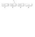
図1は本発明の実施形態に係る光信号を用いた人体の姿勢および動作判定システム10のブロック図である。図1を参照すると、前記人体の姿勢および動作判定システム10は、光信号送信モジュール100、光信号伝達モジュール200、人体状態分析モジュール300、およびユーザーインターフェース400を含む。FIG. 1 is a block diagram of a humanposture and
前記光信号送信モジュール100は、光信号を発生して出力することができる。図1に示されてはいないが、前記光信号送信モジュール100は、光信号発生器および光信号送信機を含むことができる。前記光信号送信モジュール100は、特定の波長の光信号を発生するLEDにより実現される。ところが、本発明の範囲は、これに限定されない。 The optical
前記光信号伝達モジュール200は、人体の1部位に装着可能であり、少なくとも一つの切断端部を有する少なくとも一つの光信号伝達経路を備えることができる。図2は、図1に示された一つの光信号伝達経路を含む光信号伝達モジュール200の概略構成図である。図2に概略的に示すように、光信号伝達経路は、光信号伝達経路本体210、少なくとも一つの光ファイバー支持用コネクタ220a、220b、および弾性部材230を備える。 The optical
前記少なくとも一つの光信号伝達経路の前記いずれか一つの切断端部の間隔は、前記光信号伝達モジュール200が装着された人体のいずれか1部位の周長の変化に基づいて変化させることができる。前記光信号伝達経路は、少なくとも一つの切断端部を有する光ファイバーにより実現される。ところが、本発明の範囲はこれに限定されない。 The interval between the cut ends of the at least one optical signal transmission path can be changed based on a change in the circumference of any one part of the human body to which the optical
光信号伝達経路本体210は、光ファイバー支持用コネクタ220a、220bおよび弾性部材230を支持する役目を果たし、光信号伝達経路の外皮を形成する。それだけでなく、光信号伝達経路本体210は、人体の少なくとも1部位に装着可能に設けられてもよい。例えば、光信号伝達経路本体210は、人体の腕や腰、股、ふくらはぎなどの各部位に装着可能である。よって、光信号伝達経路本体210は、ゴムバンドからなることが好ましい。光信号伝達経路が図5に示された形態に形成されるならば、ゴムバンドとしての光信号伝達経路本体210を用いて必要な人体の各部位に装着されるとよい。ところが、光信号発生モジュール200が衣服などと一体に設けられるならば、ゴムバンドとしての光信号伝達経路本体210は、衣服などに裁縫されてもよい。 The optical signal transmission path
一対の光ファイバー支持用コネクタ220a、220bは、光信号伝達経路本体210内に設けられ、前記少なくとも一つの切断端部の間隔が前記人体のいずれか1部位の周長の変化に基づいて変化するように前記光ファイバー201を支持する。図2の場合、光ファイバー201の切断された領域が一箇所なので、ここにだけ一対の光ファイバー支持用コネクタ220a、220bが設けられてもよい。ところが、本発明の範囲はこれに限定されない。例えば、前記光ファイバー201は、2つ以上の切断端部を持ってもよい。 The pair of optical
弾性部材230は、前記少なくとも一つの光ファイバー支持用コネクタ対220a、220bに結合し、前記光ファイバー支持用コネクタ220a、220bがお互い近づける方向に弾性力を加える。よって、光信号伝達モジュール200を人体のいずれか1部位、例えば脚に装着したとき、初期には、図2の(a)のように、切断された光ファイバー201の両自由端部が隣接或いは接触するが、歩いたり走ったりすると、人体部位の周長の変化量によって、図2の(b)のように、切断された光ファイバー201の両自由端部の間隔が広くなり、さらに動作を停止すると、弾性部材230によって、図2の(a)のように、切断された光ファイバー201の両自由端部が隣接或いは接触する。このような反復的メカニズムによって光ファイバー201の両自由端部における伝達される光信号の量が変化する。 The
光信号伝達経路の光信号送信モジュール100および人体状態分析モジュール300との接続部240は、光信号送信モジュール100および人体状態分析モジュール300との安定な接続のために、光ファイバー201を外部から保護することが可能な硬い材質で実現されることが好ましい。ここで、接続部240は図2に示すように、光ファイバー201の端部を締め付けて接続させる部分として使用できるうえ、光信号伝達のためのセンサーなどが取り付けられる場所にもなれる。よって、接続部240の形状は図示されたものに制限される必要はない。 The
本発明の実施形態に係る人体の姿勢および動作判定システム10は、上述したメカニズムにしたがって、光信号伝達モジュール200によって伝達される光信号の変化量、すなわち光伝達比率(light transmission rate)に基づいて、光信号伝達モジュール200が装着された人体部位の状態変化を判定することができる。The humanposture and
図3は光信号伝達モジュール200の光信号伝達特性を説明するための概念図、図4は光信号伝達モジュール200の光伝達比率を示すグラフである。図3を参照すると、光信号送信機(Transmitter)から出力される光信号に対する光信号受信機(Receiver)から受信される光信号の比率である光伝達比率(LTR:Light Transmission Rate)は光信号伝達モジュール200の装着された人体部位の周長が増加するにつれて徐々に減少することが分かる。図4を参照すると、光信号伝達モジュール200の光伝達比率(LTR)は信号伝達モジュール200の装着された人体部位の周長の変化に基づいて、すなわち人体部位の状態変化に基づいて変化することが分かる。 FIG. 3 is a conceptual diagram for explaining the optical signal transmission characteristics of the optical
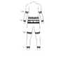
図5は衣服と一体に設けられた人体の姿勢および動作分析システム10を示す。図5において、白い線は人体の各部位に装着される光信号伝達経路を示す。衣服のベルト部分には光信号送信モジュール100および人体状態分析モジュール300が含まれてもよい。FIG. 5 showsa posture and
図5において、右腕上部の光信号伝達経路(UAr)、右腕下部の光信号伝達経路(LAr)、右脚上部の光信号伝達経路(ULr)、右脚下部の光信号伝達経路(LLr)の光伝達比率のみを用いても、人体の基本的な状態を判定することができる。以下、人体の姿勢および動作判定システム10が光信号伝達経路の光伝達比率を用いて人体の姿勢および動作を判定する簡単な例を固定姿勢と周期的運動状態に分けて考察する。In FIG. 5, the optical signal transmission path (UAr) at the upper right arm, the optical signal transmission path (LAr) at the lower right arm, the optical signal transmission path (ULr) at the upper right leg, and the optical signal transmission path (LLr) at the lower right leg. Even using only the light transmission ratio, the basic state of the human body can be determined. Hereinafter, the bodyposture and
まず、楽に横になっている状態の各光信号伝達経路の光伝達比率を初期基準値として設定した後、人体の固定姿勢判定過程を考察する。例えば、座っている姿勢は人体の腰部に装着された光信号伝達経路の光伝達比率から分かり、立っている姿勢は人体の脚上下部および腰部の光信号伝達経路の光伝達比率から分かる。 First, after setting the optical transmission ratio of each optical signal transmission path in the state of lying comfortably as an initial reference value, the process of determining the fixed posture of the human body will be considered. For example, the sitting posture can be determined from the light transmission ratio of the optical signal transmission path mounted on the waist of the human body, and the standing posture can be determined from the light transmission ratio of the optical signal transmission path of the upper and lower legs of the human body and the waist.
周期的運動状態のうち、歩いたり走ったりする運動状態は、図5に示した9部位の全ての光信号伝達経路の光伝達比率を総合的に考慮して判定できる。ところが、歩く状態と走る状態は互いに異なる光伝達比率の大きさと変化周期を持つ。 Among the periodic motion states, the motion state of walking or running can be determined by comprehensively considering the light transmission ratios of all the nine optical signal transmission paths in FIG. However, the walking state and the running state have different light transmission ratio sizes and change periods.
図6は、図1に示した人体状態分析モジュール300のブロック図である。前記人体状態分析モジュール300は、光信号伝達モジュール200の前記少なくとも一つの光信号伝達経路の前記少なくとも一つの切断端部の間隔に基づいて変化する前記少なくとも一つの光信号伝達経路の光伝達比率を算出し、人体のいずれか1部位の状態変化を判定することができる。図6を参照すると、前記人体状態分析モジュール300は、光信号受信機310、増幅器320、アナログ−デジタル変換器330、データ加工モジュール340、伝送モジュール360、受信モジュール360、および演算モジュール370を含むことができる。FIG. 6 is a block diagram of the human body
光信号受信機310は、光信号伝達モジュール200の光信号伝達経路から出力される光信号を受信し、電気的信号に変換して出力することができる。前記光信号受信機310は、前記受信される光信号に応答して駆動されるフォトダイオードで実現できる。ところが、本発明の範囲はこれに限定されない。 The
増幅器320は、前記光信号受信機から出力される信号を増幅して出力することができる。アナログ−デジタル変換器330は、前記増幅器320の出力信号をデジタル信号に変換して出力することができる。データ加工モジュール340は、前記アナログ−デジタル変換器330から出力されるデジタル信号を加工して出力することができる。前記データ加工モジュール340が行うデータ加工には、データ処理量を減少させるために、前記デジタル信号を所定のサンプリングレートでサンプリングする加工が含まれてもよい。また、前記データ加工モジュール340が行うデータ加工には、アナログ−デジタル変換器330から出力されるデジタル信号を所定の通信規格に従った信号に変換する加工が含まれてもよい。これは一つの例示に過ぎないもので、本発明の範囲を限定するものではない。 The
伝送モジュール360は、前記加工データを外部へ伝送することができる。前記伝送モジュール360は、無線通信網を用いて前記加工データを外部へ伝送することができる。前記無線通信網として、ZigBee(登録商標)通信網、Bluetooth(登録商標)通信網、WiBro(登録商標)通信網、無線インターネット網などを例示することができるが、本発明の範囲はこれに限定されない。 The
受信モジュール360は、前記伝送モジュール360から受信されるデータを受信して出力することができる。前記演算モジュール370は、前記受信されたデータに基づいて前記光信号伝達経路の光伝達比率を算出し、前記算出された光伝達比率に基づいて光信号伝達経路の装着された人体部位の状態変化を判定することができる。上述したように、多数の光信号伝達経路が人体の多数の部位に装着される場合、前記演算モジュール370は、光信号伝達経路が装着された人体の各部位の状態変化、人体の姿勢、および人体の運動状態を判定することができる。The receiving
前記人体状態分析モジュール300は、一つの装置として具現され、図5に示された人体のベルト部分に装着できる。すると、データ加工モジュール340と演算モジュール370との間を接続する伝送モジュール360および受信モジュール360は人体状態分析モジュール300で不要な要素になることもある。 The human body
ところが、上述した光信号受信機310、増幅器320、アナログ−デジタル変換器330、データ加工モジュール340、および伝送モジュール360は人体に取り付けられる別途の人体の姿勢および動作センシング装置で実現され、前記受信モジュール360および演算モジュール370は人体から分離された別途の人体の姿勢および動作判定装置で実現されてもよい。この際、前記人体の姿勢および動作センシング装置と前記人体の姿勢および動作判定装置とは、無線通信網を用いる伝送モジュール360と受信モジュール360によって互いに接続できる。よって、本発明の実施形態に係る人体の姿勢および動作判定システム10を用いると、観察者は人体から離れた遠隔から人体の姿勢および動作をモニタリングすることができる。However, the
このような本発明の実施形態に係る人体の姿勢および動作判定システム10の特徴に基づいて、前記人体の姿勢および動作判定システム10は、従来の人体の姿勢および動作判定技術とは異なり、産業現場に適用できる。ひいては、本発明の実施形態に係る人体の姿勢および動作判定システム10は、火災現場、事故現場、水中、宇宙空間などの緊急で危険な環境でも活用できるという利点を持つ。Based on such characteristics of the human bodyposture and
図1には示されていないが、人体状態分析モジュール300に接続されるユーザーインターフェース400は、前記人体の姿勢および動作判定システム10を操作するための各種操作手段、算出された光伝達比率から判定された人体の姿勢および動作などを含む人体の姿勢および動作判定システム10の動作状態に基づく各種データをディスプレイすることが可能なディスプレイ装置、および人体の姿勢および動作判定システム10の動作状態を示す各種表示手段のうち少なくとも一つを含むことができる。Although not shown in FIG. 1, the
図7は本発明の実施形態に係る人体の姿勢および動作判定方法を示すフローチャートである。次に、上述した図面を参照して、本発明の実施形態に係る人体の姿勢および動作判定方法について考察する。FIG. 7 is a flowchart showing a human bodyposture and motion determination method according to an embodiment of the present invention. Next, with reference to the above-described drawings, a human bodyposture and motion determination method according to an embodiment of the present invention will be considered.
光信号送信モジュール100は、光信号を発生して出力すると(ステップS70)、光信号伝達モジュール200は、少なくとも一つの光信号伝達経路を用いて、前記光信号送信モジュール100から出力される光信号を人体状態分析モジュール300へ伝達する(ステップS80)。すると、人体状態分析モジュール300は、少なくとも一つの光信号伝達経路の光伝達比率を算出し、算出された光伝達比率に基づいて人体のいずれか1部位の状態変化を判定することができる(ステップS90)。When the optical
図8は、図7に示される人体のいずれか1部位の状態変化判定過程を示すフローチャートである。次に、上述した図面を参照して、人体のいずれか1部位の状態変化判定過程について考察する。FIG. 8 is a flowchart showinga statechange determination process ofany one part of the human body shown in FIG. Next, with reference to the drawings described above,the state change determination processof any one part of the human body will be considered.
光信号受信機310は光信号伝達経路から受信される光信号を電気的信号に変換して出力すると(ステップS91)、増幅器320は光信号受信機310の出力信号を増幅して出力し(ステップS92)、アナログ−デジタル変換器330は増幅器320の出力信号をデジタル信号に変換して出力する(ステップS93)。 When the
データ加工モジュール340は前記デジタル信号を加工して出力し、伝送モジュール360は前記加工データを伝送する(ステップS94)。すると、受信モジュール360は、前記加工データを受信して出力し、演算モジュール370は前記受信された加工データに基づいて前記少なくとも一つの光信号伝達経路の光伝達比率を算出し、前記算出された光伝送モジュールに基づいて人体のいずれか1部位の状態変化を判定する(ステップS95)。The
本発明の実施形態に係る人体の姿勢および動作判定方法は、コンピュータが読み取り可能な記録媒体に、コンピュータが読み取れるコードとして実現できる。本発明の実施形態に係る人体の姿勢および動作判定方法は、コンピュータが読み取り可能な記録媒体に格納された前記人体の姿勢および動作判定方法を実行するためのコンピュータプログラムを実行することにより実現される。Bodyposture and operation determination method according to an embodiment of the present invention, thecomputer-readable record medium can be realized as a code that a computer can read. A human bodyposture and motion determination method according to an embodiment of the present invention is realized by executing a computer program for executing the human bodyposture and motion determination method stored in a computer-readable recording medium. .
コンピュータが読み取り可能な記録媒体は、コンピュータシステムによって読み取れるデータが格納される全種類の記録装置を含む。例えば、コンピュータ可読の記録媒体には、ROM、RAM、CD−ROM、磁気テープ、フロッピー(登録商標)ディスク、光データ格納装置などがある。 Computer-readable recording media include all types of recording devices that store data that can be read by a computer system. For example, the computer-readable recording medium includes a ROM, a RAM, a CD-ROM, a magnetic tape, a floppy (registered trademark) disk, an optical data storage device, and the like.
また、コンピュータが読み取り可能な記録媒体は、ネットワークで接続されたコンピュータシステムに分散し、分散方式でコンピュータが読み取れるコードが格納されおよび実行される。そして、本発明の実施形態に係る人体の姿勢および動作判定方法を実現するための機能的な(functional)プログラム、コードおよびコードセグメントは、本発明の属する技術分野のプログラマーによって容易に推論できる。The computer-readable recording medium is distributed to computer systems connected via a network, and codes readable by the computer are stored and executed in a distributed manner. A functional program, code, and code segment for realizing the human bodyposture and motion determination method according to the embodiment of the present invention can be easily inferred by a programmer in the technical field to which the present invention belongs.
本発明は、図示された一実施形態を参考として説明されたが、これは例示的なものに過ぎず、本技術分野における通常の知識を有する者であれば、これから種々の変形および均等な他の実施が可能であることを理解するであろう。したがって、本発明の真正な技術的保護範囲は、添付された登録請求の範囲の技術的思想によって定められるべきである。 Although the present invention has been described with reference to the illustrated embodiment, it is intended to be exemplary only and various modifications and equivalents will occur to those skilled in the art. It will be appreciated that implementation of Therefore, the true technical protection scope of the present invention should be determined by the technical idea of the appended claims.
Claims (12)
Translated fromJapanese人体の1部位に装着可能であり、少なくとも一つの切断端部を有する少なくとも一つの光信号伝達経路を備える光信号伝達モジュールと、
前記少なくとも一つの光信号伝達経路の前記少なくとも一つの切断端部の間隔に基づいて変化する前記少なくとも一つの光信号伝達経路の光伝達比率を算出し、人体のいずれか1部位の状態変化を判定する人体状態分析モジュールとを含み、
前記少なくとも一つの光信号伝達経路の前記いずれか一つの切断端部の間隔は前記人体のいずれか1部位の周長の変化に基づいて変化させることができることを特徴とする、光信号を用いた人体の姿勢および動作判定システム。An optical signal transmission module that generates and outputs an optical signal; and
An optical signal transmission module that is attachable to one part of a human body and includes at least one optical signal transmission path having at least one cut end; and
Calculate a light transmission ratio of the at least one optical signal transmission path that changes based on an interval of the at least one cut end of the at least one optical signal transmission path, and determine a state change of any one part of the human body Including a human body state analysis module,
The optical signal is used, wherein an interval between the cut ends of the at least one optical signal transmission path can be changed based on a change in a circumference of any one part of the human body. Human body posture and motion determination system.
前記少なくとも一つの光信号伝達経路から出力される光信号を受信し、電気的信号に変換して出力する光信号受信機と、
前記光信号受信機から出力される信号を増幅して出力する増幅器と、
前記増幅器から出力される信号をデジタル信号に変換して出力するアナログ−デジタル変換器と、
前記アナログ−デジタル変換器から出力されるデジタル信号に基づいて前記少なくとも一つの光信号伝達経路の光伝達比率を算出し、前記算出された前記光伝達比率に基づいて人体のいずれか1部位の状態変化を判定する演算モジュールとを含んでなることを特徴とする、請求項1に記載の光信号を用いた人体の姿勢および動作判定システム。The human body state analysis module includes:
An optical signal receiver that receives an optical signal output from the at least one optical signal transmission path, converts the optical signal into an electrical signal, and outputs the electrical signal;
An amplifier that amplifies and outputs a signal output from the optical signal receiver;
An analog-digital converter that converts the signal output from the amplifier into a digital signal and outputs the digital signal;
The optical transmission ratio of the at least one optical signal transmission path is calculated based on the digital signal output from the analog-digital converter, and the state of any one part of the human body is calculated based on the calculated optical transmission ratio The human body posture and motion determination system using an optical signal according to claim 1, further comprising an arithmetic module for determining a change.
人体の1部位に装着可能であり、少なくとも一つの切断端部を有する少なくとも一つの光信号伝達経路を用いて光信号を伝達する段階と、
前記少なくとも一つの光信号伝達経路の前記少なくとも一つの切断端部の間隔に基づいて変化する前記少なくとも一つの光信号伝達経路の光伝達比率を算出し、算出された光伝達比率に基づいて人体のいずれか1部位の状態変化を判定する段階とを含み、
前記少なくとも一つの光信号伝達経路の前記いずれか一つの切断端部の間隔は前記人体のいずれか1部位の周長の変化に基づいて変化させることができることを特徴とする、光信号を用いた人体の姿勢および動作判定方法。Generating and outputting an optical signal; and
Transmitting an optical signal using at least one optical signal transmission path that is attachable to one part of a human body and has at least one cut end; and
An optical transmission ratio of the at least one optical signal transmission path that changes based on an interval between the at least one cut end of the at least one optical signal transmission path is calculated, and a human body is calculated based on the calculated optical transmission ratio. Determining the state change of any one site,
The optical signal is used, wherein an interval between the cut ends of the at least one optical signal transmission path can be changed based on a change in a circumference of any one part of the human body. Human body posture and motion determination method.
前記光ファイバーの前記少なくとも一つの切断端部の間隔は、前記人体のいずれか1部位の周長の変化に基づいて変化させることができることを特徴とする、請求項5に記載の光信号を用いた人体の姿勢および動作判定方法。The at least one optical signal transmission path includes an optical fiber having at least one cut end;
The optical signal according to claim 5, wherein an interval between the at least one cut end portions of the optical fiber can be changed based on a change in a circumference of any one part of the human body. Human body posture and motion determination method.
光信号受信機を用いて前記少なくとも一つの光信号伝達経路から出力される光信号を受信して電気的信号に変換して出力する段階と、
前記光信号受信機から出力される信号を増幅して出力する段階と、
前記増幅されて出力される信号をデジタル信号に変換して出力する段階と、
前記出力されるデジタル信号に基づいて前記少なくとも一つの光信号伝達経路の光伝達比率を算出し、前記算出された光伝達比率に基づいて人体のいずれか1部位の状態変化を判定する段階とを含むことを特徴とする、請求項6に記載の光信号を用いた人体の姿勢および動作判定方法。Analyzing the state change of any one part of the human body,
Receiving an optical signal output from the at least one optical signal transmission path using an optical signal receiver, converting the optical signal into an electrical signal, and outputting the electrical signal;
Amplifying and outputting a signal output from the optical signal receiver;
Converting the amplified output signal into a digital signal and outputting the digital signal;
Calculating a light transmission ratio of the at least one optical signal transmission path based on the output digital signal, and determining a state change of any one part of the human body based on the calculated light transmission ratio; The method for determining the posture and motion of a human body using the optical signal according to claim 6.
人体の1部位に装着可能であり、少なくとも一つの切断端部を有する少なくとも一つの光信号伝達経路を用いて光信号を伝達する段階と、
前記少なくとも一つの光信号伝達経路から出力される光信号に基づいて発生するデータを外部へ伝送する段階とを含み、
前記少なくとも一つの光信号伝達経路の前記いずれか一つの切断端部の間隔は前記人体のいずれか1部位の周長の変化に基づいて変化させることができることを特徴とする、光信号を用いた人体の姿勢および動作判定方法。Generating and outputting an optical signal; and
Transmitting an optical signal using at least one optical signal transmission path that is attachable to one part of a human body and has at least one cut end; and
Transmitting data generated based on an optical signal output from the at least one optical signal transmission path to the outside,
The optical signal is used, wherein an interval between the cut ends of the at least one optical signal transmission path can be changed based on a change in a circumference of any one part of the human body. Human body posture and motion determination method.
前記光ファイバーの前記少なくとも一つの切断端部の間隔は、前記人体のいずれか1部位の周長の変化に基づいて変化させることができることを特徴とする、請求項8に記載の光信号を用いた人体の姿勢および動作判定方法。The at least one optical signal transmission path includes an optical fiber having at least one cut end;
The optical signal according to claim 8, wherein an interval between the at least one cut ends of the optical fiber can be changed based on a change in a circumference of any one part of the human body. Human body posture and motion determination method.
光信号受信機を用いて前記少なくとも一つの光信号伝達経路から受信される光信号を電気的信号に変換して出力する段階と、
前記光信号受信機から出力される信号を増幅して出力する段階と、
前記増幅されて出力される信号をデジタル信号に変換して出力する段階と、
前記デジタル信号を加工して出力する段階と、
前記加工して出力される加工データを外部へ伝送する段階とを含むことを特徴とする、請求項9に記載の光信号を用いた人体の姿勢および動作判定方法。Transmitting data generated based on an optical signal output from the at least one optical signal transmission path to the outside;
Converting an optical signal received from the at least one optical signal transmission path into an electrical signal using an optical signal receiver, and outputting the electrical signal;
Amplifying and outputting a signal output from the optical signal receiver;
Converting the amplified output signal into a digital signal and outputting the digital signal;
Processing and outputting the digital signal;
The method for determining posture and motion of a human body using an optical signal according to claim 9, further comprising: transmitting processed dataoutput after processing.
前記光信号伝達経路から出力される前記加工データを受信する段階と、
前記受信された加工データに基づいて前記少なくとも一つの光信号伝達経路の光伝達比率を算出し、前記算出された光伝達比率に基づいて人体のいずれか1部位の状態変化を判定する段階とを含むことを特徴とする、請求項11に記載の光信号を用いた人体の姿勢および動作判定方法。The step of determining the state of any one part of the human body based on the received processing data,
Receiving the processed data output from the optical signal transmission path;
Calculating a light transmission ratio of the at least one optical signal transmission path based on the received processing data, and determining a state change of any one part of the human body based on the calculated light transmission ratio; The method for determining the posture and motion of a human body using the optical signal according to claim 11.
Applications Claiming Priority (1)
| Application Number | Priority Date | Filing Date | Title |
|---|---|---|---|
| PCT/KR2009/007367WO2011071197A1 (en) | 2009-12-09 | 2009-12-09 | System for determining the state and motion of a human body using an optical signal, and method for determining the state of a human body |
Publications (2)
| Publication Number | Publication Date |
|---|---|
| JP2012517273A JP2012517273A (en) | 2012-08-02 |
| JP5415564B2true JP5415564B2 (en) | 2014-02-12 |
Family
ID=44145732
Family Applications (1)
| Application Number | Title | Priority Date | Filing Date |
|---|---|---|---|
| JP2011549053AExpired - Fee RelatedJP5415564B2 (en) | 2009-12-09 | 2009-12-09 | Human body posture and motion determination system using optical signal, and human body posture and motion determination method |
Country Status (5)
| Country | Link |
|---|---|
| US (1) | US20110288782A1 (en) |
| JP (1) | JP5415564B2 (en) |
| KR (1) | KR101158521B1 (en) |
| CN (1) | CN102355851A (en) |
| WO (1) | WO2011071197A1 (en) |
Families Citing this family (3)
| Publication number | Priority date | Publication date | Assignee | Title |
|---|---|---|---|---|
| KR101133223B1 (en)* | 2011-07-06 | 2012-04-05 | 에프엔티주식회사 | Human body state detecting system using optical signal |
| CN105094326A (en)* | 2015-07-20 | 2015-11-25 | 联想(北京)有限公司 | Information processing method and electronic equipment |
| US11064948B2 (en)* | 2016-04-02 | 2021-07-20 | Steven R. Peabody | Medical diagnostic device, system, and method of use |
Family Cites Families (10)
| Publication number | Priority date | Publication date | Assignee | Title |
|---|---|---|---|---|
| DE3513400A1 (en)* | 1985-04-15 | 1986-10-16 | Philips Patentverwaltung Gmbh, 2000 Hamburg | OPTICAL MOTION SENSOR |
| US4838279A (en)* | 1987-05-12 | 1989-06-13 | Fore Don C | Respiration monitor |
| JPH0283590A (en)* | 1988-09-21 | 1990-03-23 | Yamaha Corp | Musical sound controller |
| EP1558955A4 (en)* | 2002-10-15 | 2006-04-19 | Micron Optics Inc | Waferless fiber fabry-perot filters |
| JP4503311B2 (en)* | 2004-02-25 | 2010-07-14 | 本田技研工業株式会社 | Method for controlling generated torque of leg exercise assistive device |
| KR20060122567A (en)* | 2005-05-27 | 2006-11-30 | 주식회사 메리디안 | Remote biomonitoring system |
| KR100886205B1 (en)* | 2007-05-04 | 2009-02-27 | 한국전기연구원 | Polarization Type Wavelength Division Optical Image Measuring Device for Biological Diagnosis |
| KR101023446B1 (en)* | 2007-09-21 | 2011-03-25 | 주식회사 바이오에이비씨랩 | Sensors containing materials that generate electrical signals by stretching |
| KR100983256B1 (en)* | 2007-10-23 | 2010-09-24 | 건국대학교 산학협력단 | Bioelectrical signal measuring system, diagnostic system and bioelectrical signal processing method |
| KR100969783B1 (en)* | 2008-04-28 | 2010-07-13 | 한국전자통신연구원 | System and method for measuring phase response characteristics of human body in human body communication |
- 2009
- 2009-12-09JPJP2011549053Apatent/JP5415564B2/ennot_activeExpired - Fee Related
- 2009-12-09KRKR1020117012489Apatent/KR101158521B1/ennot_activeExpired - Fee Related
- 2009-12-09USUS13/146,861patent/US20110288782A1/ennot_activeAbandoned
- 2009-12-09WOPCT/KR2009/007367patent/WO2011071197A1/enactiveApplication Filing
- 2009-12-09CNCN2009801581165Apatent/CN102355851A/enactivePending
Also Published As
| Publication number | Publication date |
|---|---|
| KR101158521B1 (en) | 2012-06-20 |
| KR20110082184A (en) | 2011-07-18 |
| US20110288782A1 (en) | 2011-11-24 |
| JP2012517273A (en) | 2012-08-02 |
| WO2011071197A1 (en) | 2011-06-16 |
| CN102355851A (en) | 2012-02-15 |
Similar Documents
| Publication | Publication Date | Title |
|---|---|---|
| US20230333630A1 (en) | Program, information processor, and information processing method | |
| US20150374279A1 (en) | Sleep state estimation device, method and storage medium | |
| JP5415564B2 (en) | Human body posture and motion determination system using optical signal, and human body posture and motion determination method | |
| KR101859021B1 (en) | Child care system based on wearable device system using biometric sensor and beacon technology | |
| KR102052548B1 (en) | Apparatus for detecing wear of safety helmet and safety helmet including the same and operation method thereof | |
| JP2020503938A5 (en) | ||
| WO2017131276A1 (en) | Infant safety monitoring system using smartphone-based wearable device | |
| KR101618301B1 (en) | Wearable device and information input method using the same | |
| JP2007181673A (en) | Device for monitoring user's posture | |
| JP2009540773A (en) | Motion sensing in wireless RF networks | |
| Hong et al. | Septimu: continuous in-situ human wellness monitoring and feedback using sensors embedded in earphones | |
| JP2011097394A (en) | Danger sensing system | |
| CN109984733B (en) | Optical fiber sensing assembly, garment and motion posture monitoring system and method | |
| CN116133085A (en) | Method and apparatus for wireless broadcast and detection of data availability | |
| KR101133223B1 (en) | Human body state detecting system using optical signal | |
| JP2021181884A (en) | Excretion or flatulence detector | |
| US9635476B2 (en) | Method of preventing feedback based on detection of posture and devices for performing the method | |
| Yi et al. | 6LoWPAN-enabled fall detection and health monitoring system with Android smartphone | |
| CN105511376B (en) | Infant wearables and monitoring systems based on surface acoustic wave sensors | |
| US20140350428A1 (en) | Fluctuation detection device and fluctuation detection method | |
| TWI666618B (en) | Disaster protection device and system thereof | |
| KR200291269Y1 (en) | Glove type mouse | |
| JP2015176437A (en) | information input device and information input method | |
| JP2024011553A (en) | motion capture device | |
| TWM317056U (en) | Immobile and portable wireless alarm apparatus for detecting environment status |
Legal Events
| Date | Code | Title | Description |
|---|---|---|---|
| A131 | Notification of reasons for refusal | Free format text:JAPANESE INTERMEDIATE CODE: A131 Effective date:20130319 | |
| A521 | Request for written amendment filed | Free format text:JAPANESE INTERMEDIATE CODE: A523 Effective date:20130613 | |
| A131 | Notification of reasons for refusal | Free format text:JAPANESE INTERMEDIATE CODE: A131 Effective date:20130702 | |
| A521 | Request for written amendment filed | Free format text:JAPANESE INTERMEDIATE CODE: A523 Effective date:20130930 | |
| A01 | Written decision to grant a patent or to grant a registration (utility model) | Free format text:JAPANESE INTERMEDIATE CODE: A01 Effective date:20131022 | |
| A61 | First payment of annual fees (during grant procedure) | Free format text:JAPANESE INTERMEDIATE CODE: A61 Effective date:20131113 | |
| LAPS | Cancellation because of no payment of annual fees |