JP5415213B2 - Knife - Google Patents
KnifeDownload PDFInfo
- Publication number
- JP5415213B2 JP5415213B2JP2009229241AJP2009229241AJP5415213B2JP 5415213 B2JP5415213 B2JP 5415213B2JP 2009229241 AJP2009229241 AJP 2009229241AJP 2009229241 AJP2009229241 AJP 2009229241AJP 5415213 B2JP5415213 B2JP 5415213B2
- Authority
- JP
- Japan
- Prior art keywords
- blade
- groove
- replacement
- pair
- replaceable
- Prior art date
- Legal status (The legal status is an assumption and is not a legal conclusion. Google has not performed a legal analysis and makes no representation as to the accuracy of the status listed.)
- Active
Links
- 230000007423decreaseEffects0.000claimsdescription2
- 238000000034methodMethods0.000description4
- 230000000694effectsEffects0.000description2
- 238000003780insertionMethods0.000description2
- 230000037431insertionEffects0.000description2
- 239000002184metalSubstances0.000description2
- 230000032683agingEffects0.000description1
- 238000005452bendingMethods0.000description1
- 238000006073displacement reactionMethods0.000description1
- 238000004519manufacturing processMethods0.000description1
- 238000003801millingMethods0.000description1
- 230000001575pathological effectEffects0.000description1
- 230000007170pathologyEffects0.000description1
- 239000002994raw materialSubstances0.000description1
- 239000011347resinSubstances0.000description1
- 229920005989resinPolymers0.000description1
Images


Landscapes
- Knives (AREA)
Description
Translated fromJapanese本発明は、刀身本体に替刃を着脱可能に装着してなる刃物に関する。 The present invention relates to a blade formed by detachably attaching a replacement blade to a blade body.
顔剃りや毛髪のカット用の剃刀や、医療用、病理用のナイフなどに使用される刃物として、刀身本体に替刃を着脱可能に装着してなる刃物がある。
かかる刃物においては、刀身本体に設けた溝部に替刃を挿入することにより、替刃が刀身本体に装着される。そして、所定の使用回数や使用期間ごとに替刃を交換することができる。As a blade used for a razor for face shaving and hair cutting, a knife for medical treatment, and a pathology, there is a blade formed by detachably attaching a replacement blade to the blade body.
In such a cutter, the replacement blade is attached to the blade body by inserting the replacement blade into a groove provided in the blade body. And a replaceable blade can be replaced | exchanged for every predetermined use frequency and every use period.
ところが、製造の際の寸法誤差や経年変化などが原因で替刃と刀身本体との間に隙間が生じて、充分な挟持力が得られないことがある。また替刃は先端の挿脱口から刀身本体の溝部に着脱可能に挿脱されるが、替刃の挿脱に起因する磨耗などにより刀身本体による替刃の保持力に緩みが生じることがある。 However, there is a case where a gap is generated between the blade and the blade body due to a dimensional error or a secular change at the time of manufacture, and a sufficient clamping force may not be obtained. The replacement blade is removably inserted into and removed from the groove portion of the blade body through the insertion / removal opening at the tip, but the holding force of the replacement blade by the blade body may be loosened due to wear caused by the insertion / removal of the replacement blade.
そこで、図8〜図10に示すごとく、刀身本体92の溝部921に弾性体である板ばね94を配設した剃刀9が提案されている(特許文献1、2参照)。これにより、溝部921に装着された替刃93がこれと当接する板ばね94の付勢力で厚み方向に押圧され、替刃93が安定して保持される。この場合、溝部921における板ばね94の長手方向のずれを阻止するため、板ばね94の基端に設けた係合突片943が刀身本体92に設けた係合凹部922に係合されている。 Therefore, as shown in FIGS. 8 to 10, a
しかしながら、上記従来の剃刀9においては、上記のごとく、板ばね94を必要とする。すなわち、刀身本体92と替刃93の他に、別部材として板ばね94を溝部921に配置する必要がある。そのため、部品点数が多くなり、組み付け工程が増え、コストが高くなるという問題がある。また、刀身本体92に係合凹部922を設ける必要があるため、工数が増えるという問題もある。
その一方で、刀身本体92の弾性力によってのみ替刃93を保持するためには、予め溝部921の幅を小さくしておく必要があるが、この場合には、替刃93の装着が困難となる。However, the
On the other hand, in order to hold the
本発明は、かかる問題点に鑑みてなされたもので、替刃の装着性に優れ、かつ、部品点数が少ない低コストの刃物を提供しようとするものである。 The present invention has been made in view of such problems, and is intended to provide a low-cost blade with excellent replacement blade mounting ability and a small number of parts.
本発明は、刀身本体に替刃を着脱可能に装着してなる刃物であって、
上記刀身本体は、一体品である共に、長手方向及び厚み方向に直交する高さ方向の一端に開口すると共に長手方向の先端にも開口した溝部を形成してなり、
該溝部に上記替刃が刃先を露出させるように配置され、
上記溝部の側壁を構成する一対の壁部は、その高さ方向の開口側端部が互いに近づく方向に付勢されており、上記一対の壁部によって上記替刃が挟持されており、
上記替刃は、上記刀身本体の一対の上記壁部の上記開口側端部を当接させる支承部を有し、
上記溝部は、上記一対の壁部の各内側壁と、両内側壁の間を連結する溝底壁とを有しており、
上記替刃の背面は、上記溝底壁の何処にも接触することなく配置されて、
上記替刃の背面と上記溝部の溝底壁との間には、上記替刃の長手方向の全体にわたって背部空間が形成され、
かつ、上記溝部は、上記替刃を装着していない状態において、上記背部空間が形成される部分の幅が上記支承部を除く上記替刃の厚みよりも大きいことを特徴とする刃物にある(請求項1)。The present invention is a blade formed by detachably attaching a replacement blade to the blade body,
The blade body is anintegral part, and has a groove that opens at one end in the height direction perpendicular to the longitudinal direction and the thickness direction and also opens at the distal end in the longitudinal direction,
The replacement blade is disposed in the groove so as to expose the blade edge,
The pair of wall portions constituting the side walls of the groove portion are biased in the direction in which the opening side end portions in the height direction approach each other, and the replacement blade is sandwiched by the pair of wall portions,
The replacement blade has a support part that abuts the opening-side end parts of the pair of wall parts of the blade body,
The groove portion includes inner walls of the pair of wall portions, and a groove bottom wall that connects between the inner wall surfaces,
The rear surface of the replacement blade is arranged without contacting any part of the groove bottom wall,
Between the back of the replaceable blade and thegroove bottom wall of thegroove, a back space is formed over the entire length of the replaceable blade,
And the said groove part exists in the blade characterized by the width | variety of the part in which the said back space is formed in the state which is not mounting | wearing with the said replacement blade being larger than the thickness of the said replacement blade except the said support part ( Claim 1).
上記刃物においては、刀身本体は、一体品で構成されている。
また、上記刀身本体における一対の壁部が、上記開口側端部が互いに近づく方向に付勢されており、上記一対の壁部によって上記替刃が挟持されている。
そのため、刀身本体と替刃との間にバネ部材等を配置しなくても、刀身本体に替刃を安定して装着することができる。
これにより、部品点数が少なくなり、組み付け工程を少なくすることができ、コストを低減することができる。In the above-mentioned blade, theblade body is formed as an integral part.
Further, the pair of wall portions in the blade main body are urged in a direction in which the opening side end portions approach each other, and the replacement blade is sandwiched by the pair of wall portions.
Therefore, even if a spring member or the like is not disposed between the blade body and the replacement blade, the replacement blade can be stably attached to the blade body.
As a result, the number of parts is reduced, the assembly process can be reduced, and the cost can be reduced.
また、上記替刃の背面は上記溝底壁の何処にも接触しておらず、両者の間に上記背部空間を形成している。
そして、上記替刃を装着していない状態において、上記背部空間が形成される部分の幅が上記支承部を除く上記替刃の厚みよりも大きい。
そのため、溝部に替刃を装着する作業が簡単になる。すなわち、上記背部空間が存在する分、溝部の深さが深い。これにより、替刃と刀身本体とが平行な状態になくても、溝部における先端側の開口部に、斜めに替刃を挿入しやすくすることができる。つまり、替刃を装着する最初の段階から、上記刀身本体における一対の壁部の開口側端部を、替刃における支承部に当接させた状態にすることができる。そのため、刀身本体に替刃を円滑に挿入することができる。Further,the back surface of the replaceable blade does not contact any part of the groove bottom wall, andforms the back spacetherebetween .
And in the state which is not mounting | wearing with the said replacement blade, the width | variety of the part in which the said back space is formed is larger than the thickness of the said replacement blade except the said support part.
Therefore, the operation | work which mounts a replaceable blade in a groove part becomes easy. That is, the depth of the groove is deep as the back space exists. Thereby, even if a replaceable blade and a blade main body are not in a parallel state, it is possible to easily insert the replaceable blade obliquely into the opening on the distal end side in the groove portion. That is, from the initial stage of mounting the replacement blade, the opening side end portions of the pair of wall portions in the blade main body can be brought into contact with the support portion of the replacement blade. Therefore, the replacement blade can be smoothly inserted into the blade body.
また、上記替刃を装着していない状態において、上記背部空間が形成される部分の幅が上記支承部を除く上記替刃の厚みよりも大きいことにより、背部空間が形成される部分に、替刃の背面付近の部分を容易に挿入することができる。
そして、一旦、替刃の一部が刀身本体の溝部に挿入されれば、あとは、支承部に刀身本体の開口側端部を当接させながら、スライド挿入していくことによって、容易に替刃を刀身本体に装着することができる。
このように、上記構成によって、本発明の刃物は、替刃の装着性を高くすることができる。Further, when the replacement blade is not attached, the width of the portion where the back space is formed is larger than the thickness of the replacement blade excluding the support portion, so that the portion where the back space is formed is replaced. The portion near the back of the blade can be easily inserted.
Once a part of the replaceable blade is inserted into the groove of the blade body, the slide blade can be easily inserted by sliding it while bringing the opening end of the blade body into contact with the support. The blade can be attached to the blade body.
Thus, with the above-described configuration, the blade of the present invention can improve the mountability of the replacement blade.
また、上記刃物は、上記替刃の背面が上記溝底壁の何処にも接触することなく配置される上記背部空間を有するため、その分、溝部を深くすることができ、壁部を高くすることができる。
これにより、壁部が弾性変形するときの開口側端部のストロークを大きくすることができる。その結果、溝部に装着する替刃の厚みに多少のばらつきがあっても、一対の壁部の開口側端部によって充分な挟持力で替刃を挟持することができる。
また、替刃の非装着時における一対の壁部の開口側端部の間の間隔を充分に小さくしておくことによって、多少の経年変化が生じても、替刃を充分に挟持することが可能となる。Moreover, since the said blade hasthe said back part spacearrange |positioned without the back surface ofthe said replacement blade contacting anywhere on the said groove bottom wall, it can make a groove part deeply and can make a wall part high. be able to.
Thereby, the stroke of the opening side end when the wall is elastically deformed can be increased. As a result, even if there is some variation in the thickness of the replaceable blade attached to the groove, the replaceable blade can be clamped with a sufficient clamping force by the opening side end portions of the pair of wall portions.
In addition, by keeping the distance between the opening side end portions of the pair of wall portions when the replacement blade is not mounted sufficiently small, the replacement blade can be sufficiently clamped even if some aging occurs. It becomes possible.
以上のごとく、本発明によれば、替刃の装着性に優れ、かつ、部品点数が少ない低コストの刃物を提供することができる。 As described above, according to the present invention, it is possible to provide a low-cost blade with excellent replacement blade mounting ability and a small number of parts.
本発明において、上記刃物は、例えば、顔剃りや毛髪のカット用の剃刀や、医療用、病理用のナイフなどに使用される刃物とすることができる。
なお、本明細書において、上記刃物の長手方向における先端側と反対側を基端側として説明する。In the present invention, the blade may be a blade used for, for example, a razor for face shaving or hair cutting, a medical knife, or a pathological knife.
In the present specification, the side opposite to the distal end side in the longitudinal direction of the blade will be described as the proximal end side.
また、上記支承部は、上記替刃の厚み方向に突出した凸部であることが好ましい(請求項2)。
この場合には、上記壁部の開口側端部を確実に上記支承部に当接させやすくなる。Moreover, it is preferable that the said support part is a convex part protruded in the thickness direction of the said replaceable blade (Claim 2).
In this case, the end of the wall portion on the opening side can be reliably brought into contact with the support portion.
また、上記替刃は、上記刃先と反対側における上記支承部に隣接する部分に、上記一対の壁部の上記開口側端部によって挟持される被挟持部が設けられ、上記背面側から上記被挟持部に向って厚みが小さくなるよう形成されていることが好ましい(請求項3)。
この場合には、上記開口側端部が上記被挟持部に位置決めされ、刀身本体に対する替刃の装着状態が安定する。Further, the replacement blade is provided with a sandwiched portion that is sandwiched by the opening-side end portions of the pair of wall portions at a portion adjacent to the support portion on the side opposite to the blade edge, and from the back side, It is preferable that the thickness is reduced toward the holding portion (claim 3).
In this case, the opening-side end portion is positioned at the sandwiched portion, and the mounting state of the replacement blade with respect to the blade body is stabilized.
また、上記刃物は剃刀であることが好ましい(請求項4)。
この場合には、剃毛中や整髪中に、速やかにかつ容易に替刃交換可能であり、当該替
刃を刀身本体に緩み無く保持することができるという点で、本発明は特に剃刀に適用したときにその効果を一層発揮することができる。Moreover, it is preferable that the said cutter is a razor (Claim 4).
In this case, the present invention is particularly applicable to a razor in that the blade can be replaced quickly and easily during shaving or hair styling, and the blade can be held in the blade body without looseness. The effect can be further exerted.
本発明の実施例にかかる刃物につき、図1〜図7を用いて説明する。
本例の刃物1は、顔剃りや毛髪カット用の剃刀である。
本例の刃物1は、図1〜図3に示すごとく、刀身本体2に替刃3を着脱可能に装着してなる。
刀身本体2は、長手方向及び厚み方向に直交する高さ方向の一端に開口すると共に長手方向の先端にも開口した溝部21を形成してなる。
該溝部21に替刃3が刃先32を露出させるように配置されている。A blade according to an embodiment of the present invention will be described with reference to FIGS.
The
As shown in FIGS. 1 to 3, the
The
The
溝部21の側壁を構成する一対の壁部22は、その開口側端部221が互いに近づく方向に付勢されており、図3に示すごとく、一対の壁部22によって替刃3が挟持されている。
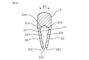
図1、図3に示すごとく、上記溝部は、上記一対の壁部22、22の各内側壁225、225と、両内側壁225の間を連結する溝底壁215とを有しており、上記替刃3の背面は、上記溝底壁215の何処にも接触することなく配置されている。そして、替刃3の背面31と溝部21の溝底壁215との間には、替刃3の長手方向の全体にわたって背部空間11が形成されている。
替刃3は、刀身本体2の一対の壁部22の開口側端部221を当接させる支承部33を有する。The pair of
As shown in FIGS. 1 and 3, thegroove has
The
溝部21は、図4のように替刃3を装着していない状態において、背部空間11が形成される部分の幅W1が支承部33を除く替刃3の厚みW2(図3)よりも大きい。
なお、背部空間11の高さH1(替刃の背面31と、溝底壁215の最も深い底面210との間)は、例えば、溝部21の深さH2の15%以上であることが好ましい。In the state where the
The height H1 of the back space 11(between the
また、図3に示すごとく、支承部33は、替刃3の厚み方向に突出した凸部である。
替刃3は、刃先32と反対側における支承部33に隣接する部分に、一対の壁部22の開口側端部221によって挟持される被挟持部34が設けられている。そして、背面31側から被挟持部34に向って厚みが小さくなるよう形成されている。Further, as shown in FIG. 3, the
The
替刃3は、図6(B)、図3に示すごとく、替刃本体320と、替刃本体320を両面及び背面から覆うガイドカバー310とからなる。ガイドカバー310は、下端に波型輪郭部312を有し、該波型輪郭部312の一部から、替刃本体320の刃先32が露出している。
支承部33は、ガイドカバー310の一部によって構成されており、替刃3の長手方向に沿って、その全体にわたって、直線状に形成されている。As shown in FIGS. 6B and 3, the
The
また、溝部21は切削加工によって形成されている。すなわち、溝部21は、刀身本体2に対して、メタルソー、フライスカッター等を用いて切削加工することによって形成される。
そして、溝部21は、図6(A)に示すごとく、刀身本体2の刀身先端231に開口した先端開口部211と、刀身本体2の高さ方向の一端(刀身下端232)に開口した下方開口部212とを有する。本例では、下方開口部212の開口方向を下方として説明する。Moreover, the
As shown in FIG. 6A, the
具体的には、図5に示すごとく、断面略長方形状の板棒状の金属体に対して、上記刀身下端232に相当する位置から、溝部21を切削加工する。この段階では、溝部21の側壁を構成する一対の壁部22は、互いに平行となっている。
次いで、図4に示すごとく、一対の壁部22を、その開口側端部221が互いに近づく方向に曲げ加工する。このとき、壁部22の付け根部分において屈曲させる。これにより、溝部21における下方開口部212の幅を狭める。替刃3の非装着時における下方開口部212の幅は、替刃3における被挟持部34の厚みよりも小さい。Specifically, as shown in FIG. 5, the
Next, as shown in FIG. 4, the pair of
そして、一対の壁部22は、弾性変形可能となっており、溝部22に替刃3を装着したときには、一対の壁部22が互いに離れる方向へ弾性変形する。つまり、替刃3を装着した状態においては、一対の壁部22が、その開口側端部221が互いに近づく方向、すなわち替刃3を挟持する方向へ、付勢されている。
なお、刀身本体2は一体品であって、複数の部材を組み付けてなるものではない。The pair of
The
また、図1、図2に示すごとく、刀身本体2には、基端部側においてハンドル4が取り付けられている。該ハンドル4は、例えば樹脂成形体からなる。
刀身本体2に対して替刃3を着脱する際には、刀身本体2に対して替刃3を長手方向へスライドさせる。そして、溝部21における先端開口部211(図6)から替刃3を挿入し、或いは離脱させる。As shown in FIGS. 1 and 2, a
When the
たとえば、図7に示すごとく、替刃3は、ケース5内に立てた状態で収納されていることがある。この場合、収納されたケース5内の替刃3を、直接刀身本体2に装着することができる。上述のごとく、替刃3の着脱時には、原則として、替刃3の長手方向と刀身本体2の長手方向とを一致させる必要がある。しかし、最初から、刀身本体2の長手方向と替刃3の長手方向とを一致させるのは困難な場合が多い。まして、下方開口部212の幅が替刃3の厚みよりも狭くなっている溝部21に、替刃3を先端開口部211から挿入するのは難しい。 For example, as shown in FIG. 7, the
そこで、図7(A)に示すごとく、替刃3に対して、斜め上方から刀身本体2の刀身先端231を当接させると共に、溝部21に替刃3の一部を挿入する。これにより、左右の位置決めがされた状態で、刀身本体2と替刃3との角度を小さくして、図7(B)に示すごとく、両者の方向を一致させる。そして、そのまま、刀身本体2と替刃3とを長手方向へ相対的にスライドさせて、替刃3を刀身本体2における所定位置に装着する。 Therefore, as shown in FIG. 7A, the
次に、本例の作用効果につき説明する。
上記刃物1においては、刀身本体2は一体品で構成されている。また、刀身本体2における一対の壁部22が、上記開口側端部221が互いに近づく方向に付勢されており、一対の壁部22によって替刃3が挟持されている。
そのため、刀身本体2と替刃3との間にバネ部材等を配置しなくても、刀身本体2に替刃3を安定して装着することができる。これにより、部品点数が少なくなり、組み付け工程を少なくすることができ、コストを低減することができる。Next, the function and effect of this example will be described.
In the
Therefore, the
また、図3に示すごとく替刃の背面31は、上記溝底壁215の何処にも接触しておらず、両者の間に背部空間11を有する。
そして、替刃3を装着していない状態において、背部空間11が形成される部分の幅W1(図4)が、支承部33を除く替刃3の最大厚みW2(図3)よりも大きい。そのため、溝部21に替刃3を装着する作業が簡単になる。
すなわち、背部空間11が存在する分、溝部21の深さが深い。これにより、替刃3と刀身本体2とが平行な状態になくても、溝部21における先端開口部211に、斜めに替刃3を挿入しやすくすることができる(図7(A))。つまり、替刃3を装着する最初の段階から、刀身本体2における一対の壁部22の開口側端部221を、替刃3における支承部33に当接させた状態にすることができる。そのため、刀身本体2に替刃3を円滑に挿入することができる。Further, asshown in FIG. 3, the
And in the state which is not mounting | wearing with the
That is, the depth of the
また、替刃3を装着していない状態において、背部空間11が形成される部分の幅W1が上記替刃3の厚みW2よりも大きいことにより、背部空間11が形成される部分に、替刃3の背面31付近の部分を容易に挿入することができる。
そして、一旦、替刃3の一部が刀身本体2の溝部21に挿入されれば、あとは、支承部33に刀身本体2の開口側端部221を当接させながら、スライド挿入していくことによって、容易に替刃3を刀身本体2に装着することができる(図7)。
このように、上記構成によって、本例の刃物1は、替刃3の装着性を高くすることができる。In addition, in the state where the
Once a part of the
Thus, with the above-described configuration, the
また、刃物1は、上記替刃の背面31が上記溝底壁215の何処にも接触していない背部空間11を有する。そのため、その分、溝部21を深くすることができ、壁部22を高くすることができる。
これにより、壁部22が弾性変形するときの開口側端部221のストロークを大きくすることができる。その結果、溝部21に装着する替刃3の厚みに多少のばらつきがあっても、一対の壁部22の開口側端部221によって充分な挟持力で替刃3を挟持することができる。また、替刃3の非装着時における一対の壁部22の開口側端部221の間の間隔(下方開口部212の幅)を充分に小さくしておくことによって、多少の経年変化が生じても、替刃3を充分に挟持することが可能となる。The
Thereby, the stroke of the opening
また、支承部33は、替刃3の厚み方向に突出した凸部であるため、壁部22の開口側端部221を確実に支承部33に当接させやすくなる。
また、図3に示すごとく、替刃3は、背面31側から被挟持部34に向って厚みが小さくなるよう形成されている。そのため、開口側端部221が被挟持部34に位置決めされ、刀身本体2に対する替刃3の装着状態が安定する。Moreover, since the
Further, as shown in FIG. 3, the
また、溝部21は、一体品の刀身本体2の素材を切削加工によって形成したものである。そのため、溝部21を容易に形成することができる。また、例えば、板状体を折り曲げ加工することによって溝部21を形成する場合等に比べて、溝部21の幅を正確に形成しやすい。Moreover, the
以上のごとく、本例によれば、替刃の装着性に優れ、かつ、部品点数が少ない低コストの刃物を提供することができる。 As described above, according to this example, it is possible to provide a low-cost blade with excellent replacement blade mounting ability and a small number of parts.
1 刃物
11 背部空間
2 刀身本体
21 溝部
22 壁部
221 開口側端部
3 替刃
31 背面
32 刃先
33 支承部DESCRIPTION OF
Claims (4)
Translated fromJapanese上記刀身本体は、一体品である共に、長手方向及び厚み方向に直交する高さ方向の一端に開口すると共に長手方向の先端にも開口した溝部を形成してなり、
該溝部に上記替刃が刃先を露出させるように配置され、
上記溝部の側壁を構成する一対の壁部は、その高さ方向の開口側端部が互いに近づく方向に付勢されており、上記一対の壁部によって上記替刃が挟持されており、
上記替刃は、上記刀身本体の一対の上記壁部の上記開口側端部を当接させる支承部を有し、
上記溝部は、上記一対の壁部の各内側壁と、両内側壁の間を連結する溝底壁とを有しており、
上記替刃の背面は、上記溝底壁の何処にも接触することなく配置されて、
上記替刃の背面と上記溝部の溝底壁との間には、上記替刃の長手方向の全体にわたって背部空間が形成され、
かつ、上記溝部は、上記替刃を装着していない状態において、上記背部空間が形成される部分の幅が上記支承部を除く上記替刃の厚みよりも大きいことを特徴とする刃物。A blade formed by detachably attaching a replacement blade to the blade body,
The blade body is anintegral part, and has a groove that opens at one end in the height direction perpendicular to the longitudinal direction and the thickness direction and also opens at the distal end in the longitudinal direction,
The replacement blade is disposed in the groove so as to expose the blade edge,
The pair of wall portions constituting the side walls of the groove portion are biased in the direction in which the opening side end portions in the height direction approach each other, and the replacement blade is sandwiched by the pair of wall portions,
The replacement blade has a support part that abuts the opening-side end parts of the pair of wall parts of the blade body,
The groove portion includes inner walls of the pair of wall portions, and a groove bottom wall that connects between the inner wall surfaces,
The rear surface of the replacement blade is arranged without contacting any part of the groove bottom wall,
Between the back of the replaceable blade and thegroove bottom wall of thegroove, a back space is formed over the entire length of the replaceable blade,
And the said groove part is a blade characterized by the width | variety of the part in which the said back space is formed in the state which is not mounting | wearing with the said replacement blade, being larger than the thickness of the said replacement blade except the said support part.
Priority Applications (1)
| Application Number | Priority Date | Filing Date | Title |
|---|---|---|---|
| JP2009229241AJP5415213B2 (en) | 2009-10-01 | 2009-10-01 | Knife |
Applications Claiming Priority (1)
| Application Number | Priority Date | Filing Date | Title |
|---|---|---|---|
| JP2009229241AJP5415213B2 (en) | 2009-10-01 | 2009-10-01 | Knife |
Publications (2)
| Publication Number | Publication Date |
|---|---|
| JP2011072698A JP2011072698A (en) | 2011-04-14 |
| JP5415213B2true JP5415213B2 (en) | 2014-02-12 |
Family
ID=44017317
Family Applications (1)
| Application Number | Title | Priority Date | Filing Date |
|---|---|---|---|
| JP2009229241AActiveJP5415213B2 (en) | 2009-10-01 | 2009-10-01 | Knife |
Country Status (1)
| Country | Link |
|---|---|
| JP (1) | JP5415213B2 (en) |
Families Citing this family (1)
| Publication number | Priority date | Publication date | Assignee | Title |
|---|---|---|---|---|
| CN110281105B (en)* | 2019-07-24 | 2024-10-01 | 蓝思科技股份有限公司 | Skin grinding and polishing equipment and skin grinding and polishing rod |
Family Cites Families (3)
| Publication number | Priority date | Publication date | Assignee | Title |
|---|---|---|---|---|
| JP3696106B2 (en)* | 2001-03-12 | 2005-09-14 | フェザー安全剃刀株式会社 | Replaceable blade razor holder |
| JP3795764B2 (en)* | 2001-04-02 | 2006-07-12 | フェザー安全剃刀株式会社 | Replaceable blade razor holder |
| JP2001353382A (en)* | 2001-06-11 | 2001-12-25 | Feather Safety Razor Co Ltd | Holder of cutting razor |
- 2009
- 2009-10-01JPJP2009229241Apatent/JP5415213B2/enactiveActive
Also Published As
| Publication number | Publication date |
|---|---|
| JP2011072698A (en) | 2011-04-14 |
Similar Documents
| Publication | Publication Date | Title |
|---|---|---|
| JP6956148B2 (en) | Shaving blade cartridge | |
| EP1932633B1 (en) | Hair clipper | |
| US10093030B2 (en) | Shaving blade cartridge | |
| WO2011108337A1 (en) | Cutting tool | |
| US8146253B2 (en) | Inner cutter of electric shaver and reciprocating electric shaver | |
| JP5750161B2 (en) | Knife | |
| EP3378611A1 (en) | Razor | |
| KR20110090249A (en) | Shaver cartridges | |
| JP5415213B2 (en) | Knife | |
| JP5107136B2 (en) | Knife | |
| JP5080423B2 (en) | Reaper | |
| JP3739476B2 (en) | Reciprocating electric razor | |
| JP4766419B2 (en) | Knife | |
| JP5335988B2 (en) | Knife | |
| CN101301757A (en) | Razor blade, razor head and razor | |
| JP2017055868A (en) | Safety razor |
Legal Events
| Date | Code | Title | Description |
|---|---|---|---|
| A621 | Written request for application examination | Free format text:JAPANESE INTERMEDIATE CODE: A621 Effective date:20120321 | |
| A131 | Notification of reasons for refusal | Free format text:JAPANESE INTERMEDIATE CODE: A131 Effective date:20130806 | |
| A521 | Request for written amendment filed | Free format text:JAPANESE INTERMEDIATE CODE: A523 Effective date:20130917 | |
| TRDD | Decision of grant or rejection written | ||
| A01 | Written decision to grant a patent or to grant a registration (utility model) | Free format text:JAPANESE INTERMEDIATE CODE: A01 Effective date:20131112 | |
| A61 | First payment of annual fees (during grant procedure) | Free format text:JAPANESE INTERMEDIATE CODE: A61 Effective date:20131113 | |
| R150 | Certificate of patent or registration of utility model | Ref document number:5415213 Country of ref document:JP Free format text:JAPANESE INTERMEDIATE CODE: R150 | |
| R250 | Receipt of annual fees | Free format text:JAPANESE INTERMEDIATE CODE: R250 | |
| R250 | Receipt of annual fees | Free format text:JAPANESE INTERMEDIATE CODE: R250 | |
| R250 | Receipt of annual fees | Free format text:JAPANESE INTERMEDIATE CODE: R250 | |
| R250 | Receipt of annual fees | Free format text:JAPANESE INTERMEDIATE CODE: R250 |