JP5413250B2 - Image processing apparatus, image processing method, and program - Google Patents
Image processing apparatus, image processing method, and programDownload PDFInfo
- Publication number
- JP5413250B2 JP5413250B2JP2010048751AJP2010048751AJP5413250B2JP 5413250 B2JP5413250 B2JP 5413250B2JP 2010048751 AJP2010048751 AJP 2010048751AJP 2010048751 AJP2010048751 AJP 2010048751AJP 5413250 B2JP5413250 B2JP 5413250B2
- Authority
- JP
- Japan
- Prior art keywords
- image
- images
- group
- mode
- displayed
- Prior art date
- Legal status (The legal status is an assumption and is not a legal conclusion. Google has not performed a legal analysis and makes no representation as to the accuracy of the status listed.)
- Expired - Fee Related
Links
Images


Classifications
- G—PHYSICS
- G06—COMPUTING OR CALCULATING; COUNTING
- G06F—ELECTRIC DIGITAL DATA PROCESSING
- G06F3/00—Input arrangements for transferring data to be processed into a form capable of being handled by the computer; Output arrangements for transferring data from processing unit to output unit, e.g. interface arrangements
- G06F3/01—Input arrangements or combined input and output arrangements for interaction between user and computer
- G06F3/048—Interaction techniques based on graphical user interfaces [GUI]
- G06F3/0487—Interaction techniques based on graphical user interfaces [GUI] using specific features provided by the input device, e.g. functions controlled by the rotation of a mouse with dual sensing arrangements, or of the nature of the input device, e.g. tap gestures based on pressure sensed by a digitiser
- G06F3/0488—Interaction techniques based on graphical user interfaces [GUI] using specific features provided by the input device, e.g. functions controlled by the rotation of a mouse with dual sensing arrangements, or of the nature of the input device, e.g. tap gestures based on pressure sensed by a digitiser using a touch-screen or digitiser, e.g. input of commands through traced gestures
- G—PHYSICS
- G06—COMPUTING OR CALCULATING; COUNTING
- G06F—ELECTRIC DIGITAL DATA PROCESSING
- G06F3/00—Input arrangements for transferring data to be processed into a form capable of being handled by the computer; Output arrangements for transferring data from processing unit to output unit, e.g. interface arrangements
- G06F3/01—Input arrangements or combined input and output arrangements for interaction between user and computer
- G06F3/048—Interaction techniques based on graphical user interfaces [GUI]
- G06F3/0481—Interaction techniques based on graphical user interfaces [GUI] based on specific properties of the displayed interaction object or a metaphor-based environment, e.g. interaction with desktop elements like windows or icons, or assisted by a cursor's changing behaviour or appearance
- G06F3/04815—Interaction with a metaphor-based environment or interaction object displayed as three-dimensional, e.g. changing the user viewpoint with respect to the environment or object
- H—ELECTRICITY
- H04—ELECTRIC COMMUNICATION TECHNIQUE
- H04N—PICTORIAL COMMUNICATION, e.g. TELEVISION
- H04N1/00—Scanning, transmission or reproduction of documents or the like, e.g. facsimile transmission; Details thereof
- H04N1/0035—User-machine interface; Control console
- H04N1/00352—Input means
- H04N1/00392—Other manual input means, e.g. digitisers or writing tablets
- H—ELECTRICITY
- H04—ELECTRIC COMMUNICATION TECHNIQUE
- H04N—PICTORIAL COMMUNICATION, e.g. TELEVISION
- H04N1/00—Scanning, transmission or reproduction of documents or the like, e.g. facsimile transmission; Details thereof
- H04N1/0035—User-machine interface; Control console
- H04N1/00405—Output means
- H04N1/00408—Display of information to the user, e.g. menus
- H04N1/0044—Display of information to the user, e.g. menus for image preview or review, e.g. to help the user position a sheet
- H04N1/00458—Sequential viewing of a plurality of images, e.g. browsing or scrolling
- H—ELECTRICITY
- H04—ELECTRIC COMMUNICATION TECHNIQUE
- H04N—PICTORIAL COMMUNICATION, e.g. TELEVISION
- H04N1/00—Scanning, transmission or reproduction of documents or the like, e.g. facsimile transmission; Details thereof
- H04N1/21—Intermediate information storage
- H04N1/2104—Intermediate information storage for one or a few pictures
- H04N1/2112—Intermediate information storage for one or a few pictures using still video cameras
- H—ELECTRICITY
- H04—ELECTRIC COMMUNICATION TECHNIQUE
- H04N—PICTORIAL COMMUNICATION, e.g. TELEVISION
- H04N1/00—Scanning, transmission or reproduction of documents or the like, e.g. facsimile transmission; Details thereof
- H04N1/387—Composing, repositioning or otherwise geometrically modifying originals
- H—ELECTRICITY
- H04—ELECTRIC COMMUNICATION TECHNIQUE
- H04N—PICTORIAL COMMUNICATION, e.g. TELEVISION
- H04N23/00—Cameras or camera modules comprising electronic image sensors; Control thereof
- H04N23/60—Control of cameras or camera modules
- H04N23/62—Control of parameters via user interfaces
- H—ELECTRICITY
- H04—ELECTRIC COMMUNICATION TECHNIQUE
- H04N—PICTORIAL COMMUNICATION, e.g. TELEVISION
- H04N23/00—Cameras or camera modules comprising electronic image sensors; Control thereof
- H04N23/60—Control of cameras or camera modules
- H04N23/63—Control of cameras or camera modules by using electronic viewfinders
- H04N23/633—Control of cameras or camera modules by using electronic viewfinders for displaying additional information relating to control or operation of the camera
- H—ELECTRICITY
- H04—ELECTRIC COMMUNICATION TECHNIQUE
- H04N—PICTORIAL COMMUNICATION, e.g. TELEVISION
- H04N23/00—Cameras or camera modules comprising electronic image sensors; Control thereof
- H04N23/60—Control of cameras or camera modules
- H04N23/667—Camera operation mode switching, e.g. between still and video, sport and normal or high- and low-resolution modes
- G—PHYSICS
- G06—COMPUTING OR CALCULATING; COUNTING
- G06F—ELECTRIC DIGITAL DATA PROCESSING
- G06F2200/00—Indexing scheme relating to G06F1/04 - G06F1/32
- G06F2200/16—Indexing scheme relating to G06F1/16 - G06F1/18
- G06F2200/163—Indexing scheme relating to constructional details of the computer
- G06F2200/1637—Sensing arrangement for detection of housing movement or orientation, e.g. for controlling scrolling or cursor movement on the display of an handheld computer
- H—ELECTRICITY
- H04—ELECTRIC COMMUNICATION TECHNIQUE
- H04N—PICTORIAL COMMUNICATION, e.g. TELEVISION
- H04N2101/00—Still video cameras
- H—ELECTRICITY
- H04—ELECTRIC COMMUNICATION TECHNIQUE
- H04N—PICTORIAL COMMUNICATION, e.g. TELEVISION
- H04N2201/00—Indexing scheme relating to scanning, transmission or reproduction of documents or the like, and to details thereof
- H04N2201/0077—Types of the still picture apparatus
- H04N2201/0084—Digital still camera
Landscapes
- Engineering & Computer Science (AREA)
- Multimedia (AREA)
- Signal Processing (AREA)
- General Engineering & Computer Science (AREA)
- Theoretical Computer Science (AREA)
- Human Computer Interaction (AREA)
- General Physics & Mathematics (AREA)
- Physics & Mathematics (AREA)
- Studio Devices (AREA)
- Controls And Circuits For Display Device (AREA)
- User Interface Of Digital Computer (AREA)
- Editing Of Facsimile Originals (AREA)
- Magnetic Resonance Imaging Apparatus (AREA)
- Apparatus For Radiation Diagnosis (AREA)
Description
Translated fromJapanese本発明は、画像処理装置に関し、特に、画像を表示させる画像処理装置および画像処理方法ならびに当該方法をコンピュータに実行させるプログラムに関する。 The present invention relates to an image processing apparatus, and more particularly to an image processing apparatus and an image processing method for displaying an image, and a program for causing a computer to execute the method.
近年、人物や動物等の被写体を撮像して画像データを生成し、この画像データを画像コンテンツとして記録するデジタルスチルカメラやデジタルビデオカメラ(例えば、カメラ一体型レコーダ)等の撮像装置が普及している。また、このように記録された複数の画像コンテンツをユーザの好みに応じて1つのグループとして決定し、この決定されたグループ単位でコンテンツ管理(例えば、撮影日単位で管理)を行うことができる撮像装置が提案されている。例えば、互いに関連する複数の画像コンテンツを1つのグループとしてコンテンツ管理を行うことができる。 In recent years, imaging devices such as a digital still camera and a digital video camera (for example, a camera-integrated recorder) that capture an image of a subject such as a person or an animal to generate image data and record the image data as image content have become widespread. Yes. In addition, it is possible to determine a plurality of image contents recorded in this way as one group according to the user's preference, and to perform content management (for example, management by shooting date) in units of the determined groups. A device has been proposed. For example, content management can be performed with a plurality of image contents related to each other as one group.
また、このように記録された各画像コンテンツを表示させる再生装置が多数提案されている。例えば、操作部材を用いたユーザ操作により画像の画送りを行い、複数の画像を順次表示させる再生装置が存在する。また、ユーザが再生装置の姿勢を変化させることにより表示部の表示内容を変更させる再生装置が存在する。 In addition, many reproducing apparatuses for displaying each image content recorded in this way have been proposed. For example, there is a playback device that performs image transfer by user operation using an operation member and sequentially displays a plurality of images. In addition, there is a playback device that changes the display content of the display unit when the user changes the attitude of the playback device.
例えば、本体の移動量や回転量を求め、これらに応じて表示部の表示内容のスクロール等を指示する情報処理装置が提案されている(例えば、特許文献1参照。)。 For example, there has been proposed an information processing apparatus that obtains the amount of movement and the amount of rotation of the main body and instructs the scrolling of the display content of the display unit in accordance with these (for example, see Patent Document 1).
上述の従来技術によれば、装置の姿勢を変化させることにより表示部の表示内容を変更させることができるため、ユーザがその装置を手で持った状態でその変更操作を容易に行うことができる。 According to the above-described prior art, since the display content of the display unit can be changed by changing the attitude of the device, the user can easily perform the change operation while holding the device by hand. .
ここで、グループ単位でコンテンツ管理が行われている場合において、所望の画像コンテンツを表示させる場合には、例えば、所望の画像コンテンツが属するグループを選択してそのグループに属する各画像コンテンツを順次表示させることが想定される。しかしながら、各グループに属する画像コンテンツの種類によっては、その画像の表示切替と、この表示切替を行うための装置の姿勢の変化とが対応しないことも想定される。この場合には、同一グループに属する互いに関連する複数の画像を表示する場合に、各画像が見難くなることが想定される。 Here, when content management is performed in units of groups, when displaying desired image content, for example, a group to which the desired image content belongs is selected and each image content belonging to the group is sequentially displayed. It is assumed that However, depending on the type of image content belonging to each group, it is also assumed that the display switching of the image does not correspond to the change in the attitude of the apparatus for performing the display switching. In this case, when displaying a plurality of images related to each other belonging to the same group, it is assumed that each image is difficult to see.
本発明はこのような状況に鑑みてなされたものであり、互いに関連する複数の画像を表示する場合に各画像を見易く表示することを目的とする。 The present invention has been made in view of such a situation, and an object thereof is to display each image in an easy-to-see manner when displaying a plurality of images related to each other.
本発明は、上記課題を解決するためになされたものであり、その第1の側面は、表示モードとして、画像群の代表画像を表示部に表示する第1モードと、上記画像群の複数画像のうち、画像処理装置の姿勢に関する姿勢情報に応じた画像を上記表示部に表示する第2モードとを有し、上記第1モードおよび上記第2モードにおける画像の表示を制御し、上記第2モードにおいて、上記姿勢情報に応じた画像を表示するための操作方法を示す操作情報を上記表示部に表示するように制御する制御部を具備する画像処理装置およびその画像処理方法ならびに当該方法をコンピュータに実行させるプログラムである。これにより、第1モードおよび第2モードにおける画像の表示を制御し、第2モードにおいて、画像処理装置の姿勢に関する姿勢情報に応じた画像を表示するための操作方法を示す操作情報を表示部に表示するという作用をもたらす。The present invention has been made to solve the above problems, a first aspect isa display mode, afirst mode for displaying a representative imageof the image group on the display unit,of the image groupamong a plurality of images, an imagecorresponding to theposition information about the orientation of the image processing apparatusand asecond mode to be displayed on the display unit,the image in thefirst modeand thesecond modecontrol the display, in the second mode, the image processing apparatusand includinga controlunitfor controllingthe operation information indicating an operation method for displaying an image according to the orientation informationto be displayedon the display unit An image processing method and a program for causing a computer to execute the method. Thiscontrols the display of the image in thefirst modeand thesecondmode,the second mode, operation information indicating an operation method for displaying an image corresponding to the attitude information about the orientation of the image processing apparatus there is an effect thatis displayedon the display unit.
また、この第1の側面において、上記複数画像のうち、所定の規則に基づく順序関係において隣接または近接する画像間の相関性に基づいて、上記複数画像を表示させるための上記操作方法を決定する決定部をさらに具備するようにしてもよい。これにより、所定の順序関係において隣接または近接する画像間の相関性に基づいて、複数画像を表示させるための操作方法を決定するという作用をもたらす。In addition, in the first embodiment,among the plurality of images, based on the correlationbetween images adjacent or close in basedrather order relationship to a predeterminedrule,the operation method for displayingthe plurality of images it may further comprisea determination unit determining.Thus, an advantage that based on the correlationbetween images adjacent or close in a predetermined orderrelationship,to determine the operating method for displayinga plurality of images.
また、この第1の側面において、上記制御部は、上記第2モードにおいて、上記姿勢情報の変化に基づき、上記画像群の複数画像を順次表示するように制御するようにしてもよい。これにより、第2モードにおいて、姿勢情報の変化に基づき、画像群の複数画像を順次表示するという作用をもたらす。In the first aspect, thecontrol unit may control to sequentially display a plurality of images in the image group based on the change in the posture information in the second mode . Accordingly, inthe second mode, there is an effect thata plurality of images in the image group are sequentially displayed based on the change in the posture information .
また、この第1の側面において、上記操作情報を上記画像群と関連付けるようにしてもよい。これにより、画像群に関連付けられている操作情報を表示するという作用をもたらす。Further, in the first aspect,the operation information may beassociate withtheabove images.Thus, an effectof displayingthe operationinformation associated with theimages set.
また、この第1の側面において、上記制御部は、上記第2モードにおいて、上記姿勢情報に基づき、上記操作情報の内容を変更するように制御するようにしてもよい。これにより、第2モードにおいて、姿勢情報に基づき、操作情報の内容を変更するという作用をもたらす。Further, in the first embodiment, the control unit,in thesecond mode, on the basis of the posture information maybe controlledso as to change the contents ofthe operation information. Thus,in the second mode, on the basis of the posture information, an effectof changing the contents of theoperation information.
また、この第1の側面において、上記制御部は、上記第2モードにおいて、上記画像群のうち、表示された画像に基づき、上記操作情報の内容を変更するように制御するようにしてもよい。これにより、第2モードにおいて、画像群のうち、表示された画像に基づき、操作情報の内容を変更するという作用をもたらす。Further, in the first embodiment, the control unit,in thesecond mode, among the image group, based on the displayed image maybe controlledto change the contents of the operation information . Thus, inthe second mode, the operation information is changed based on the displayed image in the image group .
また、この第1の側面において、上記制御部は、上記第2モードから上記第1モードに切り替わった時、上記画像群の代表画像を表示するように制御するようにしてもよい。これにより、第2モードから第1モードに切り替わった時、画像群の代表画像を表示するという作用をもたらす。Further, in the firstembodiment, the control unit,when switching from thesecond modeto the first mode maybe controlledso as to displaythe representative image of the image group. Thus,when switching from thesecond modeto the first mode, an effectof displayingthe representative images of the image group.
また、この第1の側面において、上記画像処理装置の移動量が上記姿勢情報として使用され、上記制御部は、上記第2モードにおいて、上記移動量に基づき、上記画像群の複数画像を順次表示するように制御するようにしてもよい。これにより、第2モードにおいて、画像処理装置の移動量に基づき、画像群の複数画像を順次表示するという作用をもたらす。In addition, in the firstembodiment, amountof movement of the image processing apparatusis used as the orientationinformation, the control section,at thesecondmode,-out based onthe movementamount,a plurality ofthe images You may make it control todisplay an image sequentially . Thus,in thesecondmode,-out based onthe amountof movementof the image processingapparatus, an effect ofsequentially displaying a plurality of images ofimages groups.
また、この第1の側面において、上記制御部は、上記第2モードにおいて、上記画像群の複数画像の枚数に基づき、上記画像群の複数画像を順次表示するように制御するようにしてもよい。これにより、第2モードにおいて、画像群の複数画像の枚数に基づき、画像群の複数画像を順次表示するという作用をもたらす。Further, in the first embodiment, the control unit,in thesecondmode,based on the number of multiple images of the image group, so asto controltosequentially displaythe plurality of images of the image group Also good. Thus,in thesecondmode,based on the number of multiple images of the image group, an effect ofsequentiallydisplayinga plurality of images of the image group.
本発明によれば、互いに関連する複数の画像を表示する場合に各画像を見易く表示することができるという優れた効果を奏し得る。 According to the present invention, when a plurality of images related to each other are displayed, it is possible to obtain an excellent effect that each image can be easily displayed.
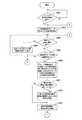
以下、本発明を実施するための形態(以下、実施の形態と称する)について説明する。説明は以下の順序により行う。
1.第1の実施の形態(表示制御:代表画像表示モードにおいて指定された代表画像に対応するグループに属する各画像を、グループ画像表示モードにおいて表示する例)
2.第2の実施の形態(表示制御:グループ画像表示モードにおける表示対象画像について間引き処理を行う例)Hereinafter, modes for carrying out the present invention (hereinafter referred to as embodiments) will be described. The description will be made in the following order.
1. First embodiment (display control: an example in which each image belonging to a group corresponding to a representative image designated in the representative image display mode is displayed in the group image display mode)
2. Second embodiment (display control: an example in which thinning processing is performed on display target images in the group image display mode)
<1.第1の実施の形態>
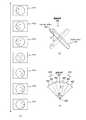
[撮像装置の外観構成例]
図1は、本発明の第1の実施の形態における撮像装置100の外観構成例を示す図である。図1(a)は、撮像装置100の表示面側の外観を示す斜視図である。また、図1(b)は、撮像装置100の表示面側の外観を示す側面図である。撮像装置100は、例えば、被写体を撮像して画像データを生成し、この画像データを画像コンテンツとして記録し、これらを表示することが可能なデジタルスチルカメラ、デジタルビデオカメラ(例えば、カメラ一体型レコーダ)等により実現される。<1. First Embodiment>
[External configuration example of imaging device]
FIG. 1 is a diagram illustrating an external configuration example of an
撮像装置100は、入出力パネル101およびシャッターボタン102を備える。また、撮像装置100は、ユーザが手に持って入出力パネル101に表示される画像を見ることができ、携帯することが可能な画像処理装置である。なお、撮像装置100は、特許請求の範囲に記載の画像処理装置の一例である。 The
入出力パネル101は、各種画像を表示するとともに、入出力パネル101における接触操作を検出することによりユーザからの操作入力を受け付けるものである。また、シャッターボタン102は、被写体を撮像して生成された画像データ(撮像画像)を画像コンテンツ(静止画ファイル)として記録する際に撮影者により押下されるボタンである。 The input /
なお、撮像装置100には、電源スイッチ、モード切替スイッチ等の他の操作部材やレンズ部等が備えられているが、説明の容易のため、ここでの図示および説明は省略する。ここで、レンズ部(図示せず)は、被写体からの光を集光する複数のレンズ、絞り等を備える光学系である。 Note that the
ここで、撮像装置100の姿勢の変化について説明する。例えば、ユーザが撮像装置100を手に持った状態で、直交3軸周りの回転角(すなわち、ヨー角、ピッチ角、ロール角)を変化させることができる。例えば、矢印300(矢印301)を軸とする矢印302方向に撮像装置100の姿勢を変化(ヨー角の変化)させることができる。この変化例を図2(b)に示す。また、例えば、矢印303(矢印304)を軸とする矢印305方向に撮像装置100の姿勢を変化(ピッチ角の変化)させることができる。また、例えば、矢印306(矢印307)を軸とする矢印308方向に撮像装置100の姿勢を変化(ロール角の変化)させることができる。 Here, a change in the posture of the
また、例えば、ユーザが撮像装置100を手に持った状態で、平面における直線上を移動(スライド)させて変化させることができる。例えば、矢印300または矢印301方向に移動させて変化させることができる(図1(b)における上下方向への移動)。また、例えば、矢印303または矢印304方向に移動させて変化させることができる(図1(b)における左右方向への移動)。この変化例を図2(c)に示す。また、例えば、矢印306または矢印307方向に移動させて変化させることができる。 Further, for example, the user can change the position by moving (sliding) on a straight line on a plane while holding the
[撮像装置の使用例]
図2は、本発明の第1の実施の形態における撮像装置100の使用時における姿勢の一例を示す図である。図2(a)には、撮像装置100を用いて画像コンテンツの再生を行う場合における撮像装置100の姿勢の一例を示す。人物310が、撮像装置100を用いて画像コンテンツの再生を行う場合には、例えば、図2(a)に示すように、撮像装置100を両手で持った状態で、入出力パネル101に表示される画像を見ることができる。[Usage example of imaging device]
FIG. 2 is a diagram illustrating an example of a posture during use of the
図2(b)および(c)には、撮像装置100の姿勢を変化させる場合におけるその遷移例を示す。図2(b)には、図1(a)に示す矢印300(301)を軸として矢印302の方向に撮像装置100を回転させてその姿勢を変化させる場合におけるその遷移例を示す。 2B and 2C show transition examples when the posture of the
図2(c)には、図1(a)および(b)に示す矢印303および304の方向に撮像装置100を移動させてその姿勢を変化させる場合におけるその遷移例を示す。本発明の第1の実施の形態では、このように撮像装置100の姿勢を変化させることにより、入出力パネル101に表示される画像を順次変更する例を示す。すなわち、ユーザによるジェスチャー操作により、入出力パネル101に表示される画像を順次変更する例を示す。これらの画像の表示状態の変更については、図7乃至図13を参照して詳細に説明する。 FIG. 2C shows a transition example in the case where the posture is changed by moving the
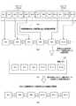
[撮像装置の機能構成例]
図3は、本発明の第1の実施の形態における撮像装置100の機能構成例を示すブロック図である。撮像装置100は、入出力部110と、姿勢検出部120と、解析部130と、制御部140と、代表画像再生部150と、グループ画像再生部160と、描画メモリ170と、画像コンテンツ記憶部200と、画像管理情報記憶部210とを備える。[Functional configuration example of imaging device]
FIG. 3 is a block diagram illustrating a functional configuration example of the
画像コンテンツ記憶部200は、撮像部(図示せず)により生成された画像データ(撮像画像)を画像ファイル(画像コンテンツ(静止画コンテンツまたは動画コンテンツ))として記憶するものである。また、画像コンテンツ記憶部200は、記憶されている画像コンテンツを代表画像再生部150またはグループ画像再生部160に供給する。なお、本発明の第1の実施の形態では、画像コンテンツとして静止画コンテンツを用いる例を示す。 The image
画像管理情報記憶部210は、画像コンテンツ記憶部200に記憶されている画像コンテンツに関する管理情報(画像管理情報)を記憶するものである。この画像管理情報を用いて、代表画像表示モードおよびグループ画像表示モードにおける再生が行われる。ここで、代表画像表示モードは、画像コンテンツ記憶部200に記憶されている画像コンテンツのうち、グループ化されている各画像コンテンツの代表画像と、グループ化されていない画像コンテンツの画像とをユーザ操作に応じて順次表示するモードである。また、グループ画像表示モードは、画像コンテンツ記憶部200に記憶されている画像コンテンツのうち、グループ化されている各画像コンテンツの画像を撮像装置100の姿勢の変化に応じて順次表示するモードである。なお、画像コンテンツ記憶部200および画像管理情報記憶部210として、例えば、DVD(Digital Versatile Disk)等のディスクやメモリカード等の半導体メモリ等のリムーバブルな1または複数の記録媒体を用いることができる。また、これらの記録媒体は、撮像装置100に内蔵するようにしてもよく、撮像装置100から着脱可能とするようにしてもよい。 The image management
入出力部110は、表示部111および操作受付部112を備える。表示部111は、代表画像再生部150またはグループ画像再生部160から供給された画像を表示する表示部である。また、表示部111には各種メニュー画面や各種画像が表示される。表示部111として、例えば、LCD(Liquid Crystal Display)、有機EL(Electro Luminescence)パネル等を用いることができる。 The input /
操作受付部112は、ユーザによって操作された操作内容を受け付ける操作受付部であり、受け付けられた操作内容に応じた操作信号を制御部140に供給する。操作受付部112は、例えば、図1に示すシャッターボタン102等の操作部材やタッチパネルに対応する。このタッチパネルは、例えば、表示部111の画面を透過するように表示部111に重ねて配置され、表示面に接触する物体を検出することによりユーザからの操作入力を受け付ける。すなわち、タッチパネルは、入出力部110における表示面において、ユーザが指を触れる等して所望の位置を押下すると、この押下位置の座標を検出し、この検出された座標に対応する操作信号を制御部140に出力する。そして、制御部140は、その操作信号を取得すると、取得された操作信号に基づいて所定の処理を実行する。操作受付部112として、例えば、専用の感知装置を用いて表示面における接触を電気信号に変換し、この変換された電気信号を制御部140に出力するタッチパネルを用いることができる。また、操作受付部112として、例えば、表示面に近接または接触する物体(例えば、ユーザの指)を検出することが可能な光センサ方式のタッチパネルを用いるようにしてもよい。なお、入出力部110は、図1に示すシャッターボタン102等の操作部材や入出力パネル101に対応する。 The
姿勢検出部120は、撮像装置100の加速度、動き、傾き等を検出することにより撮像装置100の姿勢の変化を検出するものであり、検出された姿勢の変化に関する姿勢変化情報を解析部130に出力する。例えば、姿勢検出部120は、撮像装置100の特定方向における移動方向および移動量を、撮像装置100の姿勢の変化として検出する。なお、姿勢検出部120は、ジャイロセンサ(角速度センサ)や加速度センサにより実現することができる。The
解析部130は、姿勢検出部120から出力された姿勢変化情報に基づいて、撮像装置100の姿勢の変化量(移動方向、移動量等)を解析して表示部111に表示される画像の表示切替(画送りまたは画戻し)の要否を判定するものである。そして、解析部130は、その判定結果(画像の表示切替指示)をグループ画像再生部160に出力する。具体的には、グループ画像表示モードが設定された場合には、制御部140から解析部130に解析指示および解析基準情報(画像の表示切替の要否判定に用いられる判定基準情報(例えば、図4に示す操作方法215))が出力される。また、この解析指示が出力された際における撮像装置100の姿勢の位置を基準位置とし、解析基準情報に従って、解析部130は、姿勢検出部120から出力された姿勢変化情報に基づいて、画像の表示切替の要否を判定する。そして、解析部130は、その判定結果をグループ画像再生部160に出力する。例えば、解析部130は、姿勢検出部120から出力された姿勢変化情報に基づいて、撮像装置100の姿勢が一定以上変化したか否かを判断する。続いて、解析部130は、撮像装置100の姿勢が一定以上変化した場合には、その変化が解析基準情報に応じた操作方法(図4に示す操作方法215)に対応するか否かを判断する。続いて、その変化がその操作方法に対応する場合には、解析部130が、その変化量に基づいて、画像の表示切替指示(画送りまたは画戻し指示)をグループ画像再生部160に出力する。この画像の表示切替の要否判定については、図7を参照して詳細に説明する。 The
制御部140は、操作受付部112からの操作内容に基づいて、撮像装置100の各部を制御するものである。例えば、制御部140は、操作受付部112により代表画像表示モードの設定操作が受け付けられた場合には代表画像表示モードを設定し、操作受付部112によりグループ画像表示モードの設定操作が受け付けられた場合にはグループ画像表示モードを設定する。 The
また、制御部140は、グループ画像表示モードの設定操作が受け付けられた場合には、その設定操作時に表示部111に表示されていた代表画像に対応するグループを構成する各画像を、表示部111に順次表示させる制御を行う。このグループ画像表示モードの設定時には、制御部140は、姿勢検出部120により検出された姿勢の変化と、そのグループを構成する各画像間における相関性とに基づいて、そのグループを構成する各画像を、表示部111に順次表示させる制御を行う。ここで、グループを構成する各画像間における相関性は、例えば、撮像装置100の撮像時における各画像間の相関性を意味する。例えば、図7(a)に示すように、注目被写体(例えば、人物の顔)に対する視点を変化させることにより生成された複数の画像については、その相関性として多視点画像である旨が求められる。この場合には、図7(b)に示すように、撮像装置100を横回転させることにより、そのグループを構成する各画像を順次表示させることができる。また、例えば、図11(d)に示すように、注目被写体(例えば、人物)の移動に合わせて撮像装置100を移動させることにより生成された複数の画像については、その相関性として移動中の注目被写体の動作状態画像である旨が求められる。この場合には、図11(c)に示すように、撮像装置100を横回転させることにより、そのグループを構成する各画像を順次表示させることができる。また、例えば、図12(c)に示すように、移動する注目被写体(例えば、飛行機)を、固定された撮像装置100により撮像して生成された複数の画像については、その相関性として水平移動画像である旨が求められる。この場合には、図12(a)に示すように、撮像装置100を水平移動させることにより、そのグループを構成する各画像を順次表示させることができる。これらの相関性に基づいて、図4に示す操作方法215が求められる。 Further, when the setting operation of the group image display mode is accepted, the
また、代表画像表示モードが設定されている場合に、表示部111に表示される画像の表示切替(画送り、画戻し等)を指示する指示操作が受け付けられた場合には、制御部140は、その指示操作に基づいて画像の表示切替を代表画像再生部150に指示する。また、グループ画像表示モードの設定操作時には、制御部140は、その設定操作時に表示部111に表示されていた代表画像に対応するグループに関連付けられている操作方法(図4に示す操作方法215)をグループ画像再生部160から取得する。そして、制御部140は、取得された操作方法に応じた解析基準情報および解析指示を解析部130に出力する。制御部140は、例えば、CPU(Central Processing Unit)により実現される。 Further, when the representative image display mode is set, when an instruction operation for instructing display switching (image forwarding, image returning, etc.) of the image displayed on the
代表画像再生部150は、制御部140の制御に基づいて、画像コンテンツ記憶部200に記憶されている画像コンテンツのうち、代表画像に対応する画像コンテンツと、グループ化されていない画像コンテンツを表示部111に表示させるものである。具体的には、代表画像再生部150は、代表画像表示モードが設定されている場合に、代表画像に対応する画像コンテンツと、グループ化されていない画像コンテンツとを画像コンテンツ記憶部200から取得する。続いて、代表画像再生部150は、その取得された画像コンテンツをデコードし、このデコードされた画像コンテンツに基づいて表示用の画像を描画メモリ170に描画する。そして、代表画像再生部150は、制御部140の制御に基づいて、描画メモリ170に描画された各画像のうち、1つの画像を表示部111に順次表示させる。また、代表画像再生部150は、代表画像と、これに対応するグループを構成する各画像を表示させるためのグループ画像表示モードへの設定操作を支援する操作支援情報(例えば、図6(a)に示す操作支援情報401)とを関連付けて表示部111に表示させる。 Based on the control of the
グループ画像再生部160は、制御部140の制御に基づいて、画像コンテンツ記憶部200に記憶されている画像コンテンツのうち、グループ化されている画像コンテンツをグループ単位で表示部111に表示させるものである。具体的には、グループ画像再生部160は、グループ画像表示モードが設定された場合には、グループ画像表示モードの設定操作時に表示されていた代表画像に対応するグループに属する各画像コンテンツを画像コンテンツ記憶部200から取得する。続いて、グループ画像再生部160は、その取得された画像コンテンツをデコードし、このデコードされた画像コンテンツに基づいて表示用の画像を描画メモリ170に描画する。この場合に、グループ画像再生部160は、例えば、所定の規則に従って表示用の各画像を並べて描画メモリ170に描画する。 Based on the control of the
また、グループ画像再生部160は、グループ画像表示モードの設定操作が受け付けられた場合には、表示対象となるグループに関連付けられている操作方法を示す操作支援情報と、そのグループを構成する各画像とを関連付けて表示部111に表示させる。この場合に、例えば、グループ画像再生部160は、姿勢検出部120により検出された撮像装置100の姿勢の変化に基づいて、その操作支援情報の内容を変更させる。すなわち、グループ画像再生部160は、解析部130から出力された画像の表示切替指示(画送りまたは画戻し指示)に基づいて、描画メモリ170に描画された各画像のうちから1つの画像を表示部111に順次表示させる。 Further, when a group image display mode setting operation is accepted, the group
また、例えば、グループ画像再生部160は、その操作支援情報に対応する操作方法が行われたか否かを、その姿勢の変化に基づいて判定し、その操作方法が行われた場合には、その操作支援情報を消去させるようにしてもよい。 In addition, for example, the group
描画メモリ170は、代表画像再生部150またはグループ画像再生部160により描画された画像を保持する描画バッファであり、描画された画像を代表画像再生部150またはグループ画像再生部160に供給する。 The
[画像管理情報記憶部の記憶内容]
図4は、本発明の第1の実施の形態における画像管理情報記憶部210の記憶内容を模式的に示す図である。画像管理情報記憶部210には、グループ識別情報211と、画像コンテンツ識別情報212と、グループの有無213と、代表画像214と、操作方法215とが記憶されている。[Storage contents of image management information storage unit]
FIG. 4 is a diagram schematically showing the storage contents of the image management
グループ識別情報211には、各グループを識別するための識別情報が格納されている。ここで、グループは、所定の規則に基づいて順序が特定されて互いに関連する複数の画像コンテンツにより構成される画像群である。このグループは、例えば、図7(a)および図8(a)に示す画像411乃至417により構成される。なお、本発明の第1の実施の形態では、複数の画像コンテンツにより構成される画像群(グループ)と、画像群を構成しない画像コンテンツとの双方について、グループ識別情報を付与して、画像群を構成しない画像コンテンツと画像群とを識別する例を示す。 The
画像コンテンツ識別情報212には、画像コンテンツ記憶部200に記憶されている各画像コンテンツを識別するための識別情報(画像コンテンツ識別情報)が格納される。例えば、画送り、画戻しの順序(例えば、撮影時刻(記録日時)の順序)で、各画像コンテンツの画像コンテンツ識別情報が格納されているものとする。 The image
グループの有無213には、画像コンテンツがグループ化されているか否か(画像コンテンツがグループに属するか否か)を識別するための情報が格納される。なお、図4に示す例では、グループ化されている画像コンテンツの欄には「有」を示し、グループ化されていない画像コンテンツの欄には「無」を示す。 The group presence /
代表画像214には、グループ化されている複数の画像コンテンツのうちから、代表画像を特定するための代表画像情報が格納される。図4に示す例では、代表画像情報として、代表画像に対応する画像コンテンツの画像コンテンツ識別情報(画像コンテンツ識別番号)を示す。なお、グループ化されていない画像コンテンツの欄には「無」を示す。 The
操作方法215には、グループ画像表示モードが設定されている場合において、グループ化されている複数の画像コンテンツを順次表示する際における操作方法が格納される。この操作方法は、撮像装置100の姿勢の変化に関する操作方法である。例えば、「横回転」は、図1に示す矢印300(301)を軸として矢印302の方向に撮像装置100を回転させてその姿勢を変化させることにより、複数の画像コンテンツを順次表示させる操作を意味する。また、例えば、「縦回転」は、図1に示す矢印303(304)を軸として矢印305の方向に撮像装置100を回転させてその姿勢を変化させることにより、複数の画像コンテンツを順次表示させる操作を意味する。また、例えば、「水平移動」は、図1に示す矢印303および304の方向に撮像装置100を移動させてその姿勢を変化させることにより、複数の画像コンテンツを順次表示させる操作を意味する。また、例えば、「垂直移動」は、図1に示す矢印300および301の方向に撮像装置100を移動させてその姿勢を変化させることにより、複数の画像コンテンツを順次表示させる操作を意味する。この操作方法は、例えば、画像コンテンツの生成時における撮像動作方法に応じて、撮像装置100が自動で決定することができる。また、ユーザ操作によりユーザの好みに応じて適宜決定するようにしてもよい。 The
なお、グループ識別情報211、グループの有無213、代表画像214および操作方法215に格納されている各情報については、画像ファイル(画像コンテンツ)内に記録するようにしてもよい。例えば、静止画ファイルに関する属性情報として、これらの各情報を記録することができる。そして、画像コンテンツの再生時には、画像コンテンツ内に記録されている各情報を用いることができる。 The information stored in the
[画像の表示遷移例]
図5および図6は、本発明の第1の実施の形態における入出力パネル101における画像の表示遷移例を模式的に示す図である。図5(a)には、画像コンテンツ記憶部200に記憶されている画像コンテンツを所定の規則(画像コンテンツ識別情報の順序)に従って並べた場合を模式的に示す。なお、図5(a)に示す例では、画像コンテンツ記憶部200に記憶されている画像コンテンツのうち、画像コンテンツ#1乃至#13のみを示す。また、画像コンテンツ#1乃至#13は、図4の画像コンテンツ識別情報212に示す#1乃至#13に対応する。なお、図5では、画像コンテンツ識別情報(#1乃至#13)を内部に付した矩形により、各画像コンテンツおよびこれに対応する各画像を模式的に示す。また、グループ化されている画像コンテンツについては、グループ単位で各画像コンテンツを点線の矩形で囲んで示す。[Image display transition example]
5 and 6 are diagrams schematically showing display transition examples of images on the input /
図5(b)には、代表画像表示モードが設定されている場合に入出力パネル101に表示される画像の遷移例を示す。図5(b)に示すように、グループ化されていない画像コンテンツ(#1、#5、#6、#13)と、グループ化されている画像コンテンツの代表画像(#3、#9)とが、ユーザによる画送り操作または画戻し操作に基づいて順次表示される。この画送り操作または画戻し操作は、例えば、撮像装置100に備えられている操作部材(例えば、タッチパネルや外装されている操作ボタン(図示せず))を用いて行う。また、この画送り操作または画戻し操作は、例えば、グループ画像表示モードの設定時と同様に、撮像装置100の姿勢の変化に応じて行うようにしてもよい。 FIG. 5B shows an example of transition of images displayed on the input /
図6(a)には、図5(b)に示す画像のうち、画像コンテンツ#6、#9、#13が、ユーザによる画送り操作または画戻し操作に基づいて順次表示される場合における表示遷移例を示す。なお、図6では、画像コンテンツ識別情報(#6、#8乃至#10、#13)を内部に付した矩形により画像コンテンツを表す画像を模式的に示す。このように、ユーザ操作に基づいて各画像を入出力パネル101に表示させることができる。ここで、図6(a)に示すように、グループ化されている画像コンテンツの代表画像(例えば、#9)が、入出力パネル101に表示されている場合には、グループ画像表示モードを設定するための操作支援情報401が表示される。操作支援情報401は、代表画像表示モードの設定時においてグループ画像表示モードを設定するための操作を支援するための操作ボタンである。すなわち、ユーザが操作支援情報401に対応する矩形領域を押下することにより、グループ画像表示モードを設定することができる。例えば、グループ化されている画像コンテンツ(例えば、#3、#9)の代表画像が入出力パネル101に表示されている状態で、操作支援情報401の押下操作が行われた場合にはグループ画像表示モードが設定される。このように、操作支援情報401の押下操作がグループ画像表示モードへの入り口となる。また、グループ画像表示モードが設定された場合には、グループ画像表示モードの設定操作(操作支援情報401の押下操作)が行われた際に表示されていた代表画像に対応するグループに属する各画像コンテンツが順次表示される。 FIG. 6A shows a display when
一方、図6(a)に示すように、グループ化されていない画像コンテンツ(例えば、#6、#13)が入出力パネル101に表示されている場合には、操作支援情報401が表示されない。このため、グループ化されていない画像コンテンツ(例えば、#6、#13)が入出力パネル101に表示されている状態では、操作支援情報401の押下操作が行うことができず、グループ画像表示モードを設定することができない。 On the other hand, as shown in FIG. 6A, when image content that is not grouped (for example, # 6 and # 13) is displayed on the input /
ここで、グループ化されている画像コンテンツ(#9)の代表画像が入出力パネル101に表示されている状態で、グループ画像表示モードの設定操作(操作支援情報401の押下操作)が行われた場合を想定する。この場合には、グループ画像再生部160が、グループ画像表示モードの設定操作が行われた際に表示されていた代表画像に対応するグループに属する各画像コンテンツを、画像コンテンツ記憶部200から取得する。そして、グループ画像再生部160が、その取得された画像コンテンツに基づいて、各画像を描画メモリ170に描画する。この場合に、グループ画像再生部160は、所定の規則(例えば、画像コンテンツ識別情報の順序)に従って各画像を描画メモリ170に描画する。この描画メモリ170における画像の描画例を図5(c)に示す。 Here, the group image display mode setting operation (the
図5(c)には、グループ画像表示モードが設定された際に表示されていた代表画像に対応するグループに属する各画像コンテンツが描画メモリ170に描画された場合を模式的に示す。このように画像コンテンツの描画処理が行われている場合には、グループ画像再生部160は、その旨を入出力パネル101に表示させ、グループ画像表示モードにおける表示処理を行わない。この場合における表示例を図6(b)に示す。 FIG. 5C schematically shows a case where each image content belonging to the group corresponding to the representative image displayed when the group image display mode is set is drawn in the
図6(b)には、グループ画像表示モードの設定操作が行われた直後に画像コンテンツの描画処理が行われている場合における表示例を示す。例えば、入出力パネル101には、グループ画像表示モードが設定された際に表示されていた代表画像(#9)に、画像コンテンツの描画処理である旨を示す操作支援情報402が重ねて表示される。そして、画像コンテンツの描画処理が終了した場合には、グループ画像再生部160は、グループ画像表示モードにおける画像の表示切替操作を支援するための操作支援情報を入出力パネル101に表示させる。この表示例を図6(c)に示す。 FIG. 6B shows a display example when the image content drawing process is performed immediately after the group image display mode setting operation is performed. For example, on the input /
図6(c)には、グループ画像表示モードの設定操作後に画像コンテンツの描画処理が終了した場合における表示例を示す。例えば、入出力パネル101には、グループ画像表示モードが設定された際に表示されていた代表画像(#9)に、グループ画像表示モードにおける画像の表示切替操作を支援するための操作支援情報403および404が重ねて表示される。操作支援情報403および404は、入出力パネル101に表示されているグループに属する各画像を表示させるための操作を支援するための操作ガイドである。図6(c)に示す操作支援情報403および404は、ユーザが撮像装置100を手に持った状態で、図1(a)に示す矢印300(301)を軸として撮像装置100を回転させる操作を行うことにより、画送りまたは画戻しを行うことができる旨を示す。なお、各図では、説明の容易のため、各操作支援情報を比較的大きくして示す。また、グループ画像表示モード設定時における画送り操作および画戻し操作については、図7乃至図13を参照して詳細に説明する。 FIG. 6C shows a display example when the image content drawing process is completed after the group image display mode setting operation. For example, the
ここで、図6(c)に示すように、グループ画像表示モードが設定され、表示対象画像に重ねて操作支援情報403および404が表示されている状態で、代表画像表示モードを設定する設定操作について説明する。この状態で、代表画像表示モードを設定する場合には、例えば、ユーザが入出力パネル101における表示面に接触するタッチ操作を行う。このタッチ操作が行われると、矢印405に示すように、グループ画像表示モードから代表画像表示モードに切り替えられる(すなわち、代表画像表示モードが設定される)。このように代表画像表示モードが設定された直後には、グループ画像表示モードの設定時に表示されていたグループの代表画像(例えば、画像#9)が表示される。なお、入出力パネル101におけるタッチ操作以外に、他の操作部材を用いた設定操作により代表画像表示モードを設定するようにしてもよい。 Here, as shown in FIG. 6C, the setting operation for setting the representative image display mode in a state where the group image display mode is set and the
[グループ画像表示モード設定時における撮像装置の姿勢の変化と画像の表示遷移との関係例]
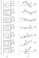
図7は、本発明の第1の実施の形態における入出力パネル101に表示される画像と撮像装置100の姿勢との関係を示す図である。図7(a)には、グループ画像表示モードが設定されている場合に連続して表示される画像411乃至417を所定の規則に従って並べて示す。画像411乃至417は、同一のグループに属する画像であり、画像414が代表画像であるものとする。また、画像411乃至417については、撮像装置100の姿勢の変化に応じて、図7(a)に示す順序で順次表示される。[Example of relationship between change in orientation of imaging device and image display transition when group image display mode is set]
FIG. 7 is a diagram illustrating a relationship between an image displayed on the input /
図7(b)には、画像411乃至417を表示する場合における撮像装置100の操作範囲を示す。この例では、図1に示す矢印300(301)を軸として撮像装置100を回転させてその姿勢を変化させることにより画送りまたは画戻しを行う例を示す。この場合における回転角度の範囲をθとする。 FIG. 7B shows an operation range of the
図7(c)には、画像411乃至417について画送りまたは画戻しを行う際に基準となる角度(基準角度)を示す。この例では、回転角度の範囲θを60度とする場合に、7つの画像(画像411乃至417)について画送りまたは画戻しを行う例について説明する。この場合には、画送りまたは画戻しを行う場合における基準角度θ1を10度(60(回転角度の範囲θ)÷6(画像411乃至417の数))とすることができる。具体的には、解析部130が、グループ画像表示モードが設定された際における撮像装置100の位置を基準位置421として設定する。そして、解析部130が、基準位置421からの回転角度(図1に示す矢印300(301)を軸420とする場合における撮像装置100の回転角度)が10度を超えた場合には、画像の表示切替指示をグループ画像再生部160に出力する。この画像の表示切替指示が出力されると、グループ画像再生部160が、その指示内容に基づいて画送りまたは画戻しを行う。 FIG. 7C shows an angle (reference angle) used as a reference when performing image advance or image return for the
例えば、グループ画像表示モードが設定された直後には、代表画像(画像414)が入出力パネル101に表示される。そして、図2(a)に示すように、人物310が撮像装置100を持った状態で、左手側が下になるように、撮像装置100の姿勢を変化させる。この場合に、グループ画像表示モードが設定された際における基準位置421からの回転角度が10度を超えた場合(回転角度の範囲422を超えた場合)には、画送りが行われる。すなわち、画像414の代わりに画像415が表示される。同様に、回転角度が10度を超える毎に(回転角度の範囲423、424を超える毎に)、画送りが行われ、画像416、417が順次表示される。 For example, the representative image (image 414) is displayed on the input /
一方、図2(a)に示すように、人物310が撮像装置100を持った状態で、右手側が下になるように、撮像装置100の姿勢を変化させる。この場合に、グループ画像表示モードが設定された際における基準位置421からの回転角度が10度を超えた場合(回転角度の範囲425を超えた場合)には、画戻しが行われる。すなわち、画像414の代わりに画像413が表示される。同様に、回転角度が10度を超える毎に(回転角度の範囲426、427を超える毎に)、画戻しが行われ、画像412、411が順次表示される。 On the other hand, as shown in FIG. 2A, the posture of the
図8および図9は、本発明の第1の実施の形態における入出力パネル101における表示遷移と、撮像装置100の姿勢との関係を概略的に示す図である。図8(a)には、入出力パネル101に表示される画像の遷移を示す。なお、図8(a)に示す入出力パネル101に表示される画像411乃至417は、図7(a)に示す画像411乃至417と同一である。また、図8(a)では、入出力パネル101に表示される画像411乃至417に重ねて表示される操作支援情報を省略して示す。この操作支援情報の表示例については、図9(a)に示す。 8 and 9 are diagrams schematically showing a relationship between display transitions in the input /
図8(b)には、図8(a)に示す入出力パネル101における画像が表示される際における撮像装置100の姿勢の一例を示す。図8(b)に示す例では、グループ画像表示モードの設定時における撮像装置100の姿勢が、水平面330に平行となっている場合における遷移例を示す。また、図8では、図8(a)に示す入出力パネル101に表示される画像と、図8(b)に示す撮像装置100の姿勢とについて、対応する関係を左右に並べて示す。 FIG. 8B shows an example of the posture of the
図9(a)には、入出力パネル101に表示される画像の遷移を示す。なお、図9(a)に示す入出力パネル101に表示される画像411、414および417は、図8(a)に示す画像411、414および417と同一である。また、図9(a)では、入出力パネル101に表示される画像412、413、415および416を省略する。上述したように、グループ画像表示モードが設定された直後には、代表画像(画像414)が入出力パネル101に表示される。この場合に、図6(c)と同様に、操作支援情報403および404が画像414に重ねて表示される。また、画像412、413、415および416が入出力パネル101に表示されている場合についても同様に、操作支援情報403および404が各画像に重ねて表示される。 FIG. 9A shows the transition of images displayed on the input /
また、グループ画像表示モードが設定されている場合において、画像411が入出力パネル101に表示されている場合には、それ以上の画戻しを行うことができない。このため、図9(a)に示すように、入出力パネル101には、画送り操作を支援するための操作支援情報431および432が画像411に重ねて表示される。また、グループ画像表示モードが設定されている場合において、画像417が入出力パネル101に表示されている場合には、それ以上の画送りを行うことができない。このため、図9(a)に示すように、入出力パネル101には、画戻し操作を支援するための操作支援情報433および434が画像411に重ねて表示される。 Further, when the group image display mode is set, when the
なお、これらの操作支援情報については、ユーザ操作により画送り画戻りが一定時間(または、一定回数)行われた場合に消去または縮小させるようにしてもよい。 Note that these pieces of operation support information may be deleted or reduced when the image transfer image return is performed for a certain time (or a certain number of times) by a user operation.
図9(b)には、図9(a)に示す入出力パネル101における画像が表示される際における撮像装置100の姿勢の一例を示す。なお、図9(b)では、図9(a)と同様に、8(b)に示す撮像装置100の姿勢の一部を省略して示す。また、図9では、図8と同様に、図9(a)に示す入出力パネル101に表示される画像と、図9(b)に示す撮像装置100の姿勢とについて、対応する関係を左右に並べて示す。 FIG. 9B shows an example of the posture of the
このように、撮像装置100を左右に傾けることにより、入出力パネル101に表示される画像の画送りまたは画戻しが行われる。また、撮像装置100を左右に傾ける操作をユーザが早く行うことにより、画送りまたは画戻しを早く行うことができる。 In this manner, the image displayed on the input /
ここで、画像411乃至417は、同一人物の顔について異なる視点から撮像された画像である。このため、撮像装置100を左右に傾けるユーザ操作を早く行い、画送りまたは画戻しを早く行うことにより、3次元の物体(人物の顔)を見ているようにユーザに認識させることができる。すなわち、撮像装置100を左右に傾けるユーザ操作により、擬似的に3次元画像を見ているようにユーザに認識させることができる。 Here, the
また、撮像装置100を左右に傾けるユーザ操作を行うことにより、擬似的に3次元画像を表示させる例として、人物の顔以外にも、他の物体を対象とすることができる。以下では、同一物体について異なる視点から撮像された画像を表示する場合における表示例を示す。 Further, as an example in which a three-dimensional image is displayed in a pseudo manner by performing a user operation for tilting the
図10は、本発明の第1の実施の形態における入出力パネル101における表示遷移例を示す図である。図10(a)および(b)には、同一の車をそれぞれ表示対象画像とする場合における入出力パネル101における表示遷移例を示す。なお、図10(a)および(b)では、画像の一部と操作支援情報とを省略して示す。 FIG. 10 is a diagram showing a display transition example in the input /
図10(a)および(b)では、例えば、回転角度の範囲θ(図7(b)に示す)を180度とする場合を例にして示す。この場合には、ユーザが撮像装置100を左右方向に傾ける操作(図1に示す矢印300(301)を軸とする場合における撮像装置100の回転操作)を行うことにより、車の左右の側面から正面側までを立体的に鑑賞することができる。 FIGS. 10A and 10B show, for example, a case where the rotation angle range θ (shown in FIG. 7B) is 180 degrees. In this case, the user performs an operation of tilting the
このように、注目被写体がさまざまな角度から撮影された画像群をユーザのジェスチャー操作により高速画送りさせることにより、擬似立体視のような画像を奥行きのある画像として楽しむことができる。すなわち、人物の顔や車等の対象物を立体的に鑑賞したい場合に、ユーザの手動操作によりその対象物の擬似的な立体画像を容易に鑑賞することができる。 In this way, by causing the user to perform high-speed image feed by capturing a group of images in which the subject of interest is photographed from various angles, it is possible to enjoy an image such as a pseudo-stereoscopic view as a deep image. That is, when it is desired to view an object such as a person's face or a car in three dimensions, a pseudo three-dimensional image of the object can be easily viewed by a user's manual operation.
なお、角度情報(図7(c)に示す回転角度の範囲θおよび基準角度θ1)については、ユーザの好みに応じて見易くなるように、ユーザ操作により変更可能とするようにしてよい。また、画像の表示切替時の判定に用いられる回転角度の範囲(基準角度)については、隣接または近接する画像間の関係に基づいて画像毎に変更するようにしてもよい。 Note that the angle information (the rotation angle range θ and the reference angle θ1 shown in FIG. 7C) may be changed by a user operation so that it can be easily seen according to the user's preference. Further, the rotation angle range (reference angle) used for determination at the time of image display switching may be changed for each image based on the relationship between adjacent or adjacent images.
また、角度情報(回転角度の範囲および基準角度)については、各グループに関連付けて画像管理情報記憶部210に記憶しておき、この記憶されている角度情報を用いてグループ画像表示モードにおける再生処理を行うようにしてもよい。この場合に、基準角度は、例えば、撮像動作時における注目被写体(例えば、人物の顔)と撮像装置100との位置関係に基づいて順次記録することができる。例えば、人物の顔を注目被写体とする場合には、その正面からの撮像位置を0度とし、その顔を中心とする撮像位置0度からの視点の角度(撮像位置に対応する角度)を順次基準角度として記録しておく。 In addition, angle information (rotation angle range and reference angle) is stored in the image management
また、角度情報(回転角度の範囲および基準角度)については、表示対象となる画像について画像処理を行うことにより求めるようにしてもよい。例えば、各画像の特徴量を抽出し、隣接または近接する画像間における特徴量を比較することにより、これらの特徴量の類似度を算出する。そして、この類似度に基づいて、基準角度を決定するようにしてもよい。例えば、類似度が大きい場合には、隣接する画像間における2つの視点の角度(その2つの視点と、被写体(1点)とを結ぶ2線により特定される角度(その1点を中心とする角度))が小さいと想定されるため、基準角度を小さくすることができる。一方、類似度が小さい場合には、隣接する画像間における2つの視点の角度が大きいと想定されるため、基準角度を大きくすることができる。なお、特徴量は、画像間における類似度を算出するためのデータであり、例えば、色や輝度等の値に基づいて抽出することができる。例えば、画像に人物の顔が含まれている場合には、その顔を構成する目や鼻、口、眉等の各部の位置関係や形状を認識するための顔画像の特徴や特性を示すデータを特徴量として用いることができる。また、例えば、各画像に含まれる顔(例えば、画像に占める割合が一定以上の顔(人物や動物))の検出処理を行い、顔が検出された場合には、画像毎の顔の向きを検出して、この顔の向きに基づいて基準角度を決定するようにしてもよい。なお、画像に含まれる顔の検出方法として、例えば、顔の輝度分布情報が記録されているテンプレートとコンテンツ画像とのマッチングによる顔検出方法(例えば、特開2004−133637参照。)を用いることができる。また、画像に含まれる肌色の部分や人間の顔の特徴量に基づいた顔検出方法を用いることができる。また、顔の向きの検出方法として、例えば、顔画像における2点間の輝度の差分値を用いた弱判別器により顔の属性(顔の向き)を検出する検出方法を用いることができる(例えば、特開2009−301170号参照。)。この場合には、例えば、顔向き判定スコアの大小に応じて、基準角度を決定することができる。また、このように求められた各基準角度に基づいて、回転角度の範囲θを求めることができる(例えば、θ=各基準角度を合計した値)。これらの角度情報の算出については、例えば、制御部140の制御に基づいて、グループ画像再生部160が行う。 Further, angle information (range of rotation angle and reference angle) may be obtained by performing image processing on an image to be displayed. For example, the feature quantities of each image are extracted, and the feature quantities between adjacent or adjacent images are compared to calculate the similarity between these feature quantities. Then, the reference angle may be determined based on the similarity. For example, when the degree of similarity is large, the angle between two viewpoints between adjacent images (the angle specified by two lines connecting the two viewpoints and the subject (one point) (centered on the one point) Since the angle)) is assumed to be small, the reference angle can be reduced. On the other hand, when the degree of similarity is small, it is assumed that the angle between the two viewpoints between adjacent images is large, so the reference angle can be increased. The feature amount is data for calculating the degree of similarity between images, and can be extracted based on values such as color and luminance, for example. For example, when a person's face is included in the image, data indicating the features and characteristics of the face image for recognizing the positional relationship and shape of each part such as the eyes, nose, mouth, and eyebrows constituting the face Can be used as a feature amount. In addition, for example, when a detection process of a face included in each image (for example, a face (person or animal) having a certain ratio or more in the image) is performed and the face is detected, the orientation of the face for each image is changed. It is also possible to detect and determine the reference angle based on the orientation of the face. As a method for detecting a face included in an image, for example, a face detection method (for example, see Japanese Patent Application Laid-Open No. 2004-133637) using matching between a template in which face luminance distribution information is recorded and a content image is used. it can. In addition, a face detection method based on a skin color part included in an image or a feature amount of a human face can be used. Further, as a method for detecting the face direction, for example, a detection method for detecting a face attribute (face direction) by a weak discriminator using a luminance difference value between two points in a face image can be used (for example, JP, 2009-301170, A). In this case, for example, the reference angle can be determined according to the magnitude of the face orientation determination score. Further, the rotation angle range θ can be obtained based on the reference angles thus obtained (for example, θ = a value obtained by adding up the reference angles). The calculation of the angle information is performed by the group
以上では、撮像装置100を所定方向に傾ける操作を行うことにより複数の画像を順次表示させ、これらの各画像を立体的に見せる例を示した。ただし、複数の画像を順次表示させる場合に、これらの画像に含まれる注目被写体を動的に見せたい場合等も想定される。また、複数の画像を順次表示させる場合には、撮像装置100を所定方向に傾ける操作よりも、所定方向に移動させる操作(スライド操作)を行う方が、操作がし易いことも想定される。そこで、以下では、これらの操作方法および表示遷移の一例について説明する。 In the above, an example in which a plurality of images are sequentially displayed by performing an operation of tilting the
図11乃至図13は、本発明の第1の実施の形態における入出力パネル101における表示遷移例と、撮像装置100の姿勢との関係を概略的に示す図である。図11には、撮像装置100を上下方向(図1に示す矢印303(304)を軸とする矢印305の方向)に傾ける操作を行うことにより、静止画を動画のように表示させる例を示す。図11に示す例では、ジョギングをする人物を注目被写体とする例を示す。 11 to 13 are diagrams schematically showing a relationship between an example of display transition in the input /
図11(a)には、入出力パネル101に表示される画像の表示例を示す。上述したように、グループ画像表示モードが設定された直後には、代表画像が入出力パネル101に表示される。この場合に、図6(c)と同様に、操作支援情報451および452が代表画像に重ねて表示される。例えば、ユーザが見ていると想定される状態を基準にして操作支援情報451および452を表示させることができる。図11(a)に示す例では、ジョギングする人物が垂直方向となるようにユーザが入出力パネル101を見ることが想定される。このため、撮像装置100の左右方向(図1(a)に示す矢印303および304方向)が、ユーザの視線方向となるように、操作支援情報451および452が表示される。なお、図11(b)に示すように、撮像装置100の上下方向(図1(a)に示す矢印300および301方向)が、ユーザの視線方向となるように、操作支援情報453および454を表示するようにしてもよい。例えば、姿勢検出部120による姿勢の変化の検出結果に基づいて、これらの表示を変更するようにしてもよい。 FIG. 11A shows a display example of an image displayed on the input /
図11(c)には、図11(d)に示す各画像を表示する場合における撮像装置100の操作範囲を示す。この例では、図1に示す矢印303(304)を軸として撮像装置100を回転させてその姿勢を変化させることにより画送りまたは画戻しを行う例を示す。この場合における回転角度の範囲をθ10とする。 FIG. 11C shows an operation range of the
図11(d)には、入出力パネル101に表示される画像の遷移を示す。図11(d)に示す入出力パネル101に表示される各画像は、撮像装置100によりジョギングをする人物が連続して撮影された画像である。なお、図11(d)では、入出力パネル101に表示される各画像に重ねて表示される操作支援情報を省略して示す。 FIG. 11D shows the transition of the image displayed on the input /
このように、高速撮影により生成された画像群をユーザのジェスチャー操作により高速画送りさせることにより、パラパラ漫画を見るような表示形態をユーザに提供することができる。 In this way, by causing the image group generated by the high-speed shooting to be fed at a high speed by the user's gesture operation, a display form in which the flip book is viewed can be provided to the user.
図12には、撮像装置100を左右方向(図1に示す矢印303および304方向)に移動させる操作を行うことにより、離陸する飛行機を動画のように表示させる例を示す。 FIG. 12 shows an example in which an airplane taking off is displayed like a moving image by performing an operation of moving the
図12(a)には、図12(c)に示す各画像を表示する場合における撮像装置100の操作範囲を示す。この例では、図1に示す矢印303および304方向に撮像装置100を移動させてその姿勢を変化させることにより画送りまたは画戻しを行う例を示す。例えば、1つの画像について画送りまたは画戻しを行う場合における撮像装置100の移動距離をd1とする。すなわち、図1に示す矢印303および304方向に撮像装置100を距離d1だけ移動させてその姿勢を変化さることにより、画送りまたは画戻りを順次行うことができる。この移動距離d1については、ユーザ操作により移動可能と判断される移動距離(全体距離)と、表示対象画像の数との関係に基づいて設定することができる。例えば、全体距離をdとし、表示対象画像の数を10とする場合には、移動距離d1=d/10とすることができる。 FIG. 12A shows an operation range of the
図12(b)には、入出力パネル101に表示される画像の表示例を示す。上述したように、グループ画像表示モードが設定された直後には、代表画像が入出力パネル101に表示される。この場合に、図6(c)と同様に、操作支援情報461および462が代表画像に重ねて表示される。この場合についても、図11に示す例と同様に、ユーザが見ていると想定される状態を基準にして操作支援情報461および462が表示される。図12(b)に示す例では、離陸する飛行機が左右方向に進むようにユーザが入出力パネル101を見ることが想定される。このため、撮像装置100の上下方向(図1(a)に示す矢印300および301方向)が、ユーザの視線方向となるように、操作支援情報461および462が表示される。 FIG. 12B shows a display example of an image displayed on the input /
図12(c)には、入出力パネル101に表示される画像の遷移を示す。図12(c)に示す入出力パネル101に表示される各画像は、撮像装置100により離陸する飛行機が連続して撮影された画像である。なお、図12(c)では、入出力パネル101に表示される各画像に重ねて表示される操作支援情報を省略して示す。 FIG. 12C shows the transition of images displayed on the input /
図13には、撮像装置100を左右方向(図1に示す矢印303および304方向)に移動させる操作を行うことにより、女子高生を動画のように表示させる例を示す。 FIG. 13 shows an example in which a high school girl is displayed like a moving image by performing an operation of moving the
図13(a)には、図13(c)に示す各画像を表示する場合における撮像装置100の操作範囲を示す。この例では、図1に示す矢印303および304方向に撮像装置100を移動させてその姿勢を変化させることにより画送りまたは画戻しを行う例を示す。例えば、1つの画像について画送りまたは画戻しを行う場合における撮像装置100の移動距離をd2とする。すなわち、図1に示す矢印303および304方向に撮像装置100を距離d2だけ移動させてその姿勢を変化さることにより、画送りまたは画戻りを順次行うことができる。この移動距離d2についても、図12(a)に示す例と同様に算出することができる。 FIG. 13A shows an operation range of the
図13(b)には、入出力パネル101に表示される画像の表示例を示す。上述したように、グループ画像表示モードが設定された直後には、代表画像が入出力パネル101に表示される。この場合に、図6(c)と同様に、操作支援情報471および472が代表画像に重ねて表示される。この場合についても、図11に示す例と同様に、ユーザが見ていると想定される状態を基準にして操作支援情報471および472が表示される。図13(b)に示す例では、女子高生が立っている状態でユーザが入出力パネル101を見ることが想定される。このため、撮像装置100の左右方向(図1(a)に示す矢印303および304方向)が、ユーザの視線方向となるように、操作支援情報471および472が表示される。 FIG. 13B shows a display example of an image displayed on the input /
図13(c)には、入出力パネル101に表示される画像の遷移を示す。図13(c)に示す入出力パネル101に表示される各画像は、撮像装置100により女子高生が連続して撮影された画像である。なお、図13(c)では、入出力パネル101に表示される各画像に重ねて表示される操作支援情報を省略して示す。 FIG. 13C shows the transition of the image displayed on the input /
なお、移動情報(全体移動の範囲および画像の表示切替時の移動距離)については、ユーザの好みに応じて見易くなるように、ユーザ操作により変更可能とするようにしてよい。また、画像の表示切替時の判定に用いられる移動距離(画像の表示切替時の移動距離)については、隣接または近接する画像間の関係に基づいて画像毎に変更するようにしてもよい。 The movement information (the range of the entire movement and the movement distance at the time of image display switching) may be changed by a user operation so that it can be easily seen according to the user's preference. Further, the moving distance (moving distance at the time of image display switching) used for determination at the time of image display switching may be changed for each image based on the relationship between adjacent or adjacent images.
また、移動情報(全体移動の範囲および画像の表示切替時の移動距離)については、各グループに関連付けて画像管理情報記憶部210に記憶しておき、この記憶されている移動情報を用いてグループ画像表示モードにおける再生処理を行うようにしてもよい。この場合に、画像の表示切替時の移動距離は、例えば、撮像動作時における注目被写体(例えば、飛行機)と撮像装置100との位置関係に基づいて順次記録することができる。例えば、飛行機を注目被写体とする場合には、その側面から所定距離だけ離れた所定位置(撮像位置)を基準とし、その撮像位置から平行移動した撮像装置100の移動量を順次記録しておく。 Further, the movement information (the range of the entire movement and the movement distance at the time of image display switching) is stored in the image management
また、移動情報(全体移動の範囲および画像の表示切替時の移動距離)については、表示対象となる画像について画像処理を行うことにより求めるようにしてもよい。例えば、各画像の特徴量を抽出し、隣接する画像間における特徴量を比較することにより、隣接する画像間における相対変位を算出する。そして、この相対変位に基づいて、隣接する画像間の移動量および移動方向を算出して、画像の表示切替時の移動距離を決定するようにしてもよい。この相対変位の算出方法として、例えば、各画像間の重複領域について互いに画素値が相関する相対変位を算出する算出方法を用いることができる。例えば、Lucas−Kanade法やブロックマッチング法等を用いて相対変位を求めることができる。また、このように求められた画像の表示切替時の移動距離に基づいて、全体移動の範囲dを求めることができる(例えば、d=各移動距離(画像の表示切替時の移動距離)を合計した値)。これらの移動情報の算出については、例えば、制御部140の制御に基づいて、グループ画像再生部160が行う。 Further, the movement information (the range of the entire movement and the movement distance at the time of image display switching) may be obtained by performing image processing on an image to be displayed. For example, the feature amount of each image is extracted, and the feature amount between adjacent images is compared to calculate the relative displacement between the adjacent images. Then, based on this relative displacement, a movement amount and a movement direction between adjacent images may be calculated to determine a movement distance when switching the display of images. As a method for calculating the relative displacement, for example, a calculation method for calculating a relative displacement in which pixel values correlate with each other for an overlapping region between images can be used. For example, the relative displacement can be obtained using a Lucas-Kanade method, a block matching method, or the like. Further, the total movement range d can be obtained based on the thus obtained movement distance at the time of display switching (for example, d = total movement distance (movement distance at the time of image display switching). Value). The movement information is calculated by the group
また、表示対象となる画像について画像処理を行うことにより、撮像装置100の姿勢の変化に関する操作方法(表示対象となる画像の操作方法(例えば、図4に示す操作方法215))を決定するようにしてもよい。例えば、上述したように、隣接する画像間における特徴量の比較により、隣接する画像間における特徴量の類似度と、隣接する画像間における相対変位とを算出する。同様に、近接する画像間における特徴量の比較により、近接する画像間における特徴量の類似度と、近接する画像間における相対変位とを算出する。すなわち、隣接または近接する画像間を比較することにより各画像間における相関性を検出する。そして、これらの類似度および相対変位に基づいて、撮像装置100の姿勢の変化に関する操作方法(表示対象となる画像の操作方法)を決定することができる。例えば、表示対象の画像に含まれる注目被写体が画像内を移動している場合には、その移動方向に応じて「水平移動」または「垂直移動」を決定することができる。また、例えば、表示対象の各画像間における特徴量の類似度が比較的高い場合には、その各画像に含まれる被写体の種類(例えば、上下方向)に応じて「横回転」または「縦回転」を決定することができる。これらの操作方法の決定については、例えば、制御部140の制御に基づいて、グループ画像再生部160が行うことができる。すなわち、グループ画像再生部160は、特許請求の範囲に記載の決定部の一例である。また、以上で示した例では、撮像装置100の上下左右の何れかの方向へのスライド、または、これらの方向を軸とする回転により入出力パネル101における表示状態を変更する例を示した。ただし、撮像装置100の前後方向(図1(a)に示す矢印306または307)への移動や、この方向を軸とする回転等により入出力パネル101における表示状態を変更するようにしてよい。例えば、撮像装置100を用いてズームイン操作またはズームアウト操作が行われた際における注目被写体の撮像画像における拡大縮小の遷移を、撮像装置100を前後に移動させる操作方法により表示させることができる。 In addition, by performing image processing on the image to be displayed, an operation method (an operation method for the image to be displayed (for example,
[撮像装置の動作例]
図14および図15は、本発明の第1の実施の形態における撮像装置100による画像コンテンツ再生処理の処理手順の一例を示すフローチャートである。この例では、グループ画像表示モードが設定されてから一定時間経過後に操作支援情報を消去する例を示す。[Operation example of imaging device]
14 and 15 are flowcharts illustrating an example of a processing procedure of image content reproduction processing by the
最初に、画像コンテンツの表示指示操作が行われたか否かが判断され(ステップS901)、その表示指示操作が行われていない場合には監視を継続して行う。一方、その表示指示操作が行われた場合には(ステップS901)、制御部140が代表画像表示モードを設定し、代表画像再生部150が、代表画像およびグループ化されていない画像を表示部111に表示させる(ステップS902)。 First, it is determined whether or not an image content display instruction operation has been performed (step S901). If the display instruction operation has not been performed, monitoring is continued. On the other hand, when the display instruction operation is performed (step S901), the
続いて、代表画像表示モードが設定されている状態で、画送り操作または画戻し操作が行われたか否かが判断される(ステップS903)。画送り操作または画戻し操作が行われた場合には(ステップS903)、代表画像再生部150が表示部111に表示されている画像の表示切替を行う(ステップS904)。すなわち、表示部111に表示されている画像の画送りまたは画戻しが行われる。 Subsequently, it is determined whether an image forwarding operation or an image returning operation has been performed in a state where the representative image display mode is set (step S903). When the image forwarding operation or the image returning operation is performed (step S903), the representative
また、画送り操作または画戻し操作が行われていない場合には(ステップS903)、グループ画像表示モードの設定操作が行われたか否かが判断され(ステップS905)、グループ画像表示モードの設定操作が行われていない場合には、ステップS916に進む。一方、グループ画像表示モードの設定操作が行われた場合には(ステップS905)、制御部140がグループ画像表示モードを設定する。そして、グループ画像再生部160が、その設定操作時に表示部111に表示されていた代表画像に対応するグループに属する各画像コンテンツと、その操作方法とを画像コンテンツ記憶部200から取得する(ステップS906)。 If no image forwarding operation or image returning operation has been performed (step S903), it is determined whether or not a group image display mode setting operation has been performed (step S905), and a group image display mode setting operation is performed. If not, the process proceeds to step S916. On the other hand, when the group image display mode setting operation is performed (step S905), the
続いて、グループ画像再生部160が、取得された画像コンテンツをデコードし、このデコードされた画像コンテンツに基づいて表示用の画像を描画メモリ170に描画する(ステップS907)。続いて、グループ画像再生部160が、描画メモリ170に描画された画像のうちの1つ(代表画像)を表示部111に表示させる(ステップS908)。 Subsequently, the group
続いて、グループ画像表示モードが設定されてから一定時間が経過したか否かが判断される(ステップS909)。グループ画像表示モードが設定されてから一定時間が経過していない場合には(ステップS909)、グループ画像再生部160が、表示部111に表示されている画像に応じて操作支援情報を表示部111に表示させる(ステップS910)。一方、グループ画像表示モードが設定されてから一定時間が経過した場合には(ステップS909)、グループ画像再生部160が、表示部111に表示されていた操作支援情報を消去させる(ステップS911)。 Subsequently, it is determined whether or not a predetermined time has elapsed since the group image display mode was set (step S909). If a certain time has not elapsed since the group image display mode was set (step S909), the group
続いて、解析部130が、姿勢検出部120から出力された姿勢変化情報に基づいて、撮像装置100の姿勢が一定以上変化したか否かを判断する(ステップS912)。そして、撮像装置100の姿勢が一定以上変化した場合には(ステップS912)、解析部130は、その変化が表示対象グループに関連付けられている操作方法(図4に示す操作方法215)に対応するか否かを判断する(ステップS913)。その変化が表示対象グループに関連付けられている操作方法に対応する場合には(ステップS913)、解析部130が、その変化量に基づいて、表示部111に表示される画像の表示切替指示(画送りまたは画戻し指示)をグループ画像再生部160に出力する。そして、グループ画像再生部160が、その表示切替指示に基づいて、表示部111に表示される画像の表示切替(画送りまたは画戻し)を行い(ステップS914)、ステップS909に戻る。一方、その変化が表示対象グループに関連付けられている操作方法に対応していない場合には(ステップS913)、ステップS915に進む。 Subsequently, based on the posture change information output from the
また、撮像装置100の姿勢が一定以上変化していない場合には(ステップS912)、代表画像表示モードの設定操作が行われたか否かが判断され(ステップS915)、その設定操作が行われた場合には、ステップS902に戻る。一方、代表画像表示モードの設定操作が行われていない場合には(ステップS915)、画像コンテンツの表示終了操作が行われたか否かが判断され(ステップS916)、その表示終了操作が行われた場合には、画像コンテンツ再生処理の動作を終了する。また、画像コンテンツの表示終了操作が行われていない場合には(ステップS916)、グループ画像表示モードが設定されているか否かが判断される(ステップS917)。そして、グループ画像表示モードが設定されている場合には(ステップS917)、ステップS909に戻り、グループ画像表示モードが設定されていない場合(すなわち、代表画像表示モードが設定されている場合)には、ステップS903に戻る。
If the posture of the
<2.第2の実施の形態>
本発明の第1の実施の形態では、グループ画像表示モードの設定操作時に表示されていた代表画像に対応するグループに属する各画像をその設定時に表示する例を示した。ここで、グループ画像表示モードの設定時に表示対象となるグループに属する画像の数が多い場合が想定される。この場合には、そのグループに属する全ての画像をユーザ操作に基づいて順次表示させることができる。しかしながら、ユーザによる操作範囲については限界があり、また、同一グループに属する各画像は、似ている画像が多く存在することも想定される。そこで、本発明の第2の実施の形態では、グループ画像表示モードの設定時に表示対象となるグループに属する画像の数が基準を越えた場合には、そのグループに属する各画像について間引き処理を行った後に、間引き後の各画像を表示させる例を示す。<2. Second Embodiment>
In the first embodiment of the present invention, an example is shown in which each image belonging to the group corresponding to the representative image displayed during the group image display mode setting operation is displayed during the setting. Here, it is assumed that the number of images belonging to the group to be displayed is large when setting the group image display mode. In this case, all the images belonging to the group can be sequentially displayed based on the user operation. However, there is a limit to the operation range by the user, and it is assumed that there are many similar images in each image belonging to the same group. Therefore, in the second embodiment of the present invention, when the number of images belonging to the group to be displayed exceeds the reference when setting the group image display mode, a thinning process is performed for each image belonging to the group. After that, an example of displaying each image after thinning is shown.
なお、本発明の第2の実施の形態における撮像装置の機能構成については、グループ画像再生部160が間引き処理を行った後に、間引き後の各画像を表示させる点以外は、図3に示す例と略同様である。このため、本発明の第1の実施の形態と共通する部分については、同一の符号を付して、これらの説明の一部を省略する。 Note that the functional configuration of the imaging apparatus according to the second embodiment of the present invention is the example shown in FIG. 3 except that the group
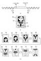
[グループ画像表示モード設定時における表示対象画像の間引き例]
図16は、本発明の第2の実施の形態におけるグループ画像再生部160による間引き処理の流れを模式的に示す図である。[Example of thinning the display target image when the group image display mode is set]
FIG. 16 is a diagram schematically illustrating the flow of the thinning process by the group
図16(a)には、画像コンテンツ記憶部200に記憶されている画像コンテンツのうち、代表画像表示モードにおける表示対象画像がユーザによる画送り操作または画戻し操作に基づいて順次表示される場合における表示遷移例を示す。なお、画像#56は、グループ化されている画像コンテンツの代表画像であり、画像#51および#63は、グループ化されていない画像コンテンツの画像であるものとする。また、この表示例は、表示対象となる画像が異なる点以外は、図6(a)に示す表示例と同様であるため、ここでの説明を省略する。 FIG. 16A illustrates a case where, among the image contents stored in the image
図16(b)には、グループ画像表示モードの設定操作時に表示されていた代表画像に対応するグループに属する各画像コンテンツについて行われた間引き処理の流れを模式的に示す。なお、代表画像(画像#56)に対応するグループ#111に属する各画像コンテンツ(#52乃至#62)の数は11であるものとする。 FIG. 16B schematically shows the flow of the thinning process performed for each image content belonging to the group corresponding to the representative image displayed during the group image display mode setting operation. Note that the number of image contents (# 52 to # 62) belonging to the
ここで、グループ化されている画像コンテンツ(#56)の代表画像が入出力パネル101に表示されている状態で、ユーザによるグループ画像表示モードの設定操作(操作支援情報401の押下操作)が行われた場合を想定する。この場合には、グループ画像再生部160が、グループ画像表示モードの設定操作時に表示されていた代表画像に対応するグループに属する各画像コンテンツを、画像コンテンツ記憶部200から取得する。続いて、グループ画像再生部160が、その取得された画像コンテンツの数が一定値を超えているか否かを判断する。続いて、その取得された画像コンテンツの数が一定値を超えていない場合には、グループ画像再生部160が、その取得された画像コンテンツに基づいて、各画像を描画メモリ170に描画する。一方、その取得された画像コンテンツの数が一定値を超えている場合には、グループ画像再生部160が、その取得された画像コンテンツについて間引き処理を行い、この間引き後の画像コンテンツに基づいて、各画像を描画メモリ170に描画する。すなわち、グループ画像再生部160は、制御部140の制御に基づいて、グループ画像表示モードの操作時において、その取得された画像コンテンツの数が一定値を超えている場合には、所定数の画像コンテンツを抽出する。そして、この抽出された画像コンテンツが表示対象画像となる。なお、この間引き処理では、例えば、その取得された画像コンテンツの数が一定値の範囲内となるように間引きが行われる。 Here, in the state where the representative image of the grouped image content (# 56) is displayed on the input /
ここで、間引き処理を行うか否かを判断する際に用いられる一定値について説明する。この一定値は、例えば、ユーザにより撮像装置100の姿勢を変化させることが可能な範囲と、この範囲における1つの画像の表示切替範囲との関係に基づいて決定することができる。例えば、図1(a)に示す矢印300および301を軸として撮像装置100を左右方向に回転させる場合を例にして説明する。例えば、ユーザにより撮像装置100の姿勢を変化させることが可能な範囲(撮像装置100を左右方向に回転させる際の回転角度)を90度とし、この範囲における1つの画像の表示切替角度を5度とする。この場合には、間引き処理を行う際に用いられる一定値を18(90÷5)とすることができる。 Here, the fixed value used when determining whether or not to perform the thinning process will be described. This constant value can be determined based on, for example, a relationship between a range in which the posture of the
また、その一定値は、例えば、グループ画像再生部160が、画像コンテンツ記憶部200から画像コンテンツを読み込む時間と、ユーザが許容することができる待ち時間との関係に基づいて決定することができる。例えば、グループ画像再生部160が、画像コンテンツ記憶部200から画像コンテンツを読み込む時間(1枚当りの時間)を100msec(ミリ秒)とし、ユーザが許容することができる待ち時間を3秒とする。この場合には、間引き処理を行う際に用いられる一定値を30(3÷0.1)とすることができる。 Further, the fixed value can be determined based on, for example, the relationship between the time when the group
また、その一定値として、例えば、撮像素子の視野角、描画メモリ170に展開することができる画像の数等に基づいて決定するようにしてもよい。なお、撮像素子は、例えば、CCD(Charge Coupled Devices)やCMOS(Complementary Metal Oxide Semiconductor)である。 Further, the fixed value may be determined based on, for example, the viewing angle of the image sensor, the number of images that can be developed in the
ここで、図16(b)に示す例では、間引き処理を行う際に用いられる一定値を6とする場合について説明する。例えば、グループ画像表示モードの設定操作時に表示されていた代表画像(画像#56)に対応するグループ#111に属する各画像コンテンツ(#52乃至#62)の数は11である。このため、グループ画像再生部160が、画像コンテンツ記憶部200から取得された画像コンテンツの数(11)が一定値(6)を超えていると判断し、その取得された画像コンテンツについて間引き処理を行う。例えば、図16(b)に示すように、グループ画像再生部160が、グループ#111に属する各画像コンテンツ(#52乃至#62)から一定間隔(1つおき)毎に5つの画像コンテンツを間引きする。この間引き処理では、例えば、間引き後の画像に代表画像が含まれるように間引きを行うようにすることが好ましい。また、例えば、画像コンテンツの属性や画像間における相関性の高さに基づいて、間引き処理を行うようにしてもよい。例えば、画像コンテンツに人物の顔が含まれている場合には、その顔の表情に関する評価値が高い画像を優先的に残すように間引き処理を行うようにすることができる。 Here, in the example shown in FIG. 16B, a case where the constant value used when performing the thinning process is 6 will be described. For example, the number of image contents (# 52 to # 62) belonging to the
このように間引きされた画像コンテンツ(#52、#54、#56、#58、#60、#62(図16(b)では、太線の枠で示す))に基づいて、グループ画像再生部160が、各画像を描画メモリ170に描画する。 Based on the thinned image content (# 52, # 54, # 56, # 58, # 60, # 62 (indicated by a bold frame in FIG. 16B)), the group
[撮像装置の動作例]
図17は、本発明の第2の実施の形態における撮像装置100による画像コンテンツ再生処理の処理手順の一例を示すフローチャートである。この処理手順は、図14および図15の変形例であり、間引き処理を行う点が図14および図15とは異なる。また、この点以外については、図14および図15と同一であるため、図14および図15と共通する部分については、同一の符号を付してこれらの説明を省略する。[Operation example of imaging device]
FIG. 17 is a flowchart illustrating an example of a processing procedure of image content reproduction processing by the
グループ画像表示モードにおいて表示対象となるグループに属する各画像およびその操作方法が取得された後(ステップS906)、グループ画像再生部160が、取得された画像の数が基準を超えているか否かを判断する(ステップS921)。そして、取得された画像の数が基準を超えている場合には(ステップS921)、グループ画像再生部160が、取得された画像の数が基準の範囲内となるように間引き処理を行う(ステップS922)。一方、取得された画像の数が基準を超えていない場合には(ステップS921)、ステップS907に進む。 After each image belonging to the group to be displayed in the group image display mode and the operation method thereof are acquired (step S906), the group
このように、グループ画像表示モードにおける表示対象画像の数が多い場合には、表示対象画像が適切な数となるように間引き処理を行うことにより、グループ画像表示モードの設定時に表示される画像を見易くすることができる。すなわち、ユーザが撮像装置100の姿勢を操作することが可能な範囲内で、画送り戻しを行うことができる。このため、ユーザの意図しない範囲での画送り操作または画戻し操作を行うことを防止することができる。 As described above, when the number of display target images in the group image display mode is large, the image displayed when setting the group image display mode is performed by performing the thinning process so that the display target images become an appropriate number. Easy to see. That is, it is possible to perform image sending back within a range in which the user can operate the posture of the
また、グループ画像表示モードにおける表示対象画像の数が多い場合には、表示対象画像が適切な数となるように間引き処理を行うことにより、グループ画像再生部160が、全ての表示対象画像を読み出す必要がない。このため、表示対象画像の読み出し時間を短縮することができ、グループ画像表示モードにおける画像再生が開始されるまでの待ち時間を軽減することができる。 When the number of display target images in the group image display mode is large, the group
以上で示したように、本発明の実施の形態によれば、ユーザ操作により代表画像表示モードおよびグループ画像表示モードの切替操作が容易に行うことができるため、ユーザ好みの各画像を容易に表示させることができる。例えば、操作支援情報(例えば、図6(a)に示す操作支援情報401)の押下操作のみで、グループ画像表示モードの設定操作を行うことができる。また、グループ画像表示モードの設定時には、表示面へのタッチ操作のみで代表画像表示モードの設定操作を行うことができる。 As described above, according to the embodiment of the present invention, since the switching operation between the representative image display mode and the group image display mode can be easily performed by the user operation, each user-preferred image can be easily displayed. Can be made. For example, the group image display mode setting operation can be performed only by pressing the operation support information (for example, the
また、グループ画像表示モードの設定時には、グループ化された画像群をユーザによるジェスチャー操作に合わせた高速な画送り画戻しができるため、ジェスチャー操作によるユーザの楽しみをさらに演出することができる。 In addition, when the group image display mode is set, the grouped images can be returned at high speed according to the gesture operation by the user, so that the enjoyment of the user by the gesture operation can be further enhanced.
また、グループ画像表示モードの設定時には、ジェスチャー操作に合わせた操作支援情報(操作ガイド)を表示画像に関連付けて表示するため、ユーザをスムーズにジェスチャー操作へ導くことができる。また、グループ画像表示モードの設定時には、表示対象となる各画像を描画メモリ170に描画しておくため、画送り画戻し毎に表示対象画像を読み出す必要がなく、ユーザのジェスチャー操作に応じた滑らかな画送り画戻しを行うことができる。また、グループ画像表示モードの設定時には、ユーザ操作による操作可能範囲に合わせた画送り画戻しを行うことができるため、ユーザの意図しない領域での画送り画戻しを防止することができる。これにより、ユーザが心地よいと思う操作範囲内において画送り画戻し操作を行うことができる。 Further, when the group image display mode is set, the operation support information (operation guide) according to the gesture operation is displayed in association with the display image, so that the user can be smoothly guided to the gesture operation. Further, when setting the group image display mode, each image to be displayed is drawn in the
また、代表画像表示モードの設定時には、代表画像のみを読み出して表示することにより、通常再生の画送り画戻し時間を高速化することができるため、ユーザに与える不快感(例えば、待ち時間による不快感)を軽減させることができる。また、代表画像表示モードの設定時には、ジェスチャー操作を行わないことにより、ユーザの意図しないジェスチャー操作による誤動作を防止することができる。 In addition, when setting the representative image display mode, it is possible to speed up the image playback image return time for normal playback by reading and displaying only the representative image. (Pleasure) can be reduced. Further, when the representative image display mode is set, by not performing the gesture operation, it is possible to prevent a malfunction due to a gesture operation unintended by the user.
このように、本発明の実施の形態によれば、互いに関連する複数の画像を表示する場合に各画像を見易く表示することができる。 Thus, according to the embodiment of the present invention, when a plurality of images related to each other are displayed, each image can be displayed in an easily viewable manner.
なお、本発明の実施の形態では、撮像装置を例にして説明したが、記録媒体に記憶されている画像コンテンツを表示部に表示させることが可能な画像処理装置に本発明の実施の形態を適用することができる。例えば、撮像機能付き携帯電話機、ナビゲーションシステム、携帯型メディアプレイヤー等の画像処理装置に本発明の実施の形態を適用することができる。 In the embodiment of the present invention, the imaging apparatus has been described as an example. However, the embodiment of the present invention is applied to an image processing apparatus capable of displaying the image content stored in the recording medium on the display unit. Can be applied. For example, the embodiment of the present invention can be applied to an image processing apparatus such as a mobile phone with an imaging function, a navigation system, and a portable media player.
なお、本発明の実施の形態は本発明を具現化するための一例を示したものであり、本発明の実施の形態において明示したように、本発明の実施の形態における事項と、特許請求の範囲における発明特定事項とはそれぞれ対応関係を有する。同様に、特許請求の範囲における発明特定事項と、これと同一名称を付した本発明の実施の形態における事項とはそれぞれ対応関係を有する。ただし、本発明は実施の形態に限定されるものではなく、本発明の要旨を逸脱しない範囲において実施の形態に種々の変形を施すことにより具現化することができる。 The embodiment of the present invention shows an example for embodying the present invention. As clearly shown in the embodiment of the present invention, the matters in the embodiment of the present invention and the claims Each invention-specific matter in the scope has a corresponding relationship. Similarly, the matters specifying the invention in the claims and the matters in the embodiment of the present invention having the same names as the claims have a corresponding relationship. However, the present invention is not limited to the embodiments, and can be embodied by making various modifications to the embodiments without departing from the gist of the present invention.
また、本発明の実施の形態において説明した処理手順は、これら一連の手順を有する方法として捉えてもよく、また、これら一連の手順をコンピュータに実行させるためのプログラム乃至そのプログラムを記憶する記録媒体として捉えてもよい。この記録媒体として、例えば、CD(Compact Disc)、MD(MiniDisc)、DVD(Digital Versatile Disk)、メモリカード、ブルーレイディスク(Blu-ray Disc(登録商標))等を用いることができる。 The processing procedure described in the embodiment of the present invention may be regarded as a method having a series of these procedures, and a program for causing a computer to execute the series of procedures or a recording medium storing the program May be taken as As this recording medium, for example, a CD (Compact Disc), an MD (MiniDisc), a DVD (Digital Versatile Disk), a memory card, a Blu-ray Disc (registered trademark), or the like can be used.
100 撮像装置
101 入出力パネル
102 シャッターボタン
110 入出力部
111 表示部
112 操作受付部
120 姿勢検出部
130 解析部
140 制御部
150 代表画像再生部
160 グループ画像再生部
170 描画メモリ
200 画像コンテンツ記憶部
210 画像管理情報記憶部DESCRIPTION OF
Claims (19)
Translated fromJapanese前記第1モードおよび前記第2モードにおける画像の表示を制御し、前記第2モードにおいて、前記姿勢情報に応じた画像を表示するための操作方法を示す操作情報を前記表示部に表示するように制御する制御部を具備する画像処理装置。As a display mode, a first mode for displaying a representative image of the image group on the display unit, and a second mode for displaying, on the display unit, an image corresponding to the posture information related to the posture of the image processing apparatus among the plurality of images of the image group. Mode
Control display of images in the first mode and the second mode, and display operation information indicating an operation method for displaying an image corresponding to the posture information on the display unit in the second mode. An image processing apparatus including a control unit for controlling.
前記制御部は、前記第2モードにおいて、前記移動量に基づき、前記画像群の複数画像を順次表示するように制御する
請求項1記載の画像処理装置。The amount of movement of the image processing device is used as the posture information,
The image processing apparatus according to claim 1, wherein the control unit controls to sequentially display a plurality of images of the image group based on the movement amount in the second mode.
前記第2モードにおいて、前記姿勢情報に応じた画像を表示するための操作方法を示す操作情報を前記表示部に表示する制御手順と
を具備する画像処理方法。A first mode in which a representative image of the image group is displayed on the display unit, and a second mode in which an image corresponding to the posture information related to the posture of the image processing apparatus among the plurality of images in the image group is displayed on the display unit. Steps to switch based on operation,
An image processing method comprising: a control procedure for displaying operation information indicating an operation method for displaying an image according to the posture information on the display unit in the second mode.
前記制御手順は、前記第2モードにおいて、前記移動量に基づき、前記画像群の複数画像を順次表示する
請求項10記載の画像処理方法。The amount of movement of the image processing device is used as the posture information,
The image processingmethod according to claim 10, wherein the control procedure sequentially displays a plurality of images of the image group based on the movement amount in the second mode.
前記第2モードにおいて、前記姿勢情報に応じた画像を表示するための操作方法を示す操作情報を前記表示部に表示する制御手順と
をコンピュータに実行させるプログラム。A first mode in which a representative image of the image group is displayed on the display unit, and a second mode in which an image corresponding to the posture information related to the posture of the image processing apparatus among the plurality of images in the image group is displayed on the display unit. Steps to switch based on operation,
In the second mode, a program for causing a computer to execute a control procedure for displaying operation information indicating an operation method for displaying an image according to the posture information on the display unit.
Priority Applications (16)
| Application Number | Priority Date | Filing Date | Title |
|---|---|---|---|
| JP2010048751AJP5413250B2 (en) | 2010-03-05 | 2010-03-05 | Image processing apparatus, image processing method, and program |
| EP17153573.5AEP3179353B1 (en) | 2010-03-05 | 2011-02-03 | Image processing device, image processing method and program |
| CN2011800125105ACN102792255A (en) | 2010-03-05 | 2011-02-03 | Image processing device, image processing method and program |
| CN201710377479.4ACN107315512B (en) | 2010-03-05 | 2011-02-03 | Image processing apparatus, image processing method, and program |
| US13/581,693US8970765B2 (en) | 2010-03-05 | 2011-02-03 | Image processing device, image processing method and program |
| BR112012021791ABR112012021791A2 (en) | 2010-03-05 | 2011-02-03 | image processing device and method, and non-transient recording medium |
| RU2012136955/08ARU2012136955A (en) | 2010-03-05 | 2011-02-03 | IMAGE PROCESSING DEVICE, IMAGE PROCESSING METHOD AND PROGRAM |
| EP11750304.5AEP2542955B1 (en) | 2010-03-05 | 2011-02-03 | Image processing device, image processing method and program |
| KR1020127022478AKR20130036181A (en) | 2010-03-05 | 2011-02-03 | Image processing device, image processing method and program |
| PCT/JP2011/000616WO2011108190A1 (en) | 2010-03-05 | 2011-02-03 | Image processing device, image processing method and program |
| TW100105989ATWI463392B (en) | 2010-03-05 | 2011-02-23 | Image processing device, image processing method and program cross-reference to related application |
| US14/589,083US9325904B2 (en) | 2010-03-05 | 2015-01-05 | Image processing device, image processing method and program |
| US15/063,640US10244176B2 (en) | 2010-03-05 | 2016-03-08 | Image processing device, image processing method and program |
| US15/846,878US10033932B2 (en) | 2010-03-05 | 2017-12-19 | Image processing device, image processing method and program |
| US16/272,386US10708506B2 (en) | 2010-03-05 | 2019-02-11 | Image processing device, image processing method and program |
| US16/857,576US20200252547A1 (en) | 2010-03-05 | 2020-04-24 | Image Processing Device, Image Processing Method and Program |
Applications Claiming Priority (1)
| Application Number | Priority Date | Filing Date | Title |
|---|---|---|---|
| JP2010048751AJP5413250B2 (en) | 2010-03-05 | 2010-03-05 | Image processing apparatus, image processing method, and program |
Publications (3)
| Publication Number | Publication Date |
|---|---|
| JP2011188061A JP2011188061A (en) | 2011-09-22 |
| JP2011188061A5 JP2011188061A5 (en) | 2013-04-04 |
| JP5413250B2true JP5413250B2 (en) | 2014-02-12 |
Family
ID=44541861
Family Applications (1)
| Application Number | Title | Priority Date | Filing Date |
|---|---|---|---|
| JP2010048751AExpired - Fee RelatedJP5413250B2 (en) | 2010-03-05 | 2010-03-05 | Image processing apparatus, image processing method, and program |
Country Status (9)
| Country | Link |
|---|---|
| US (6) | US8970765B2 (en) |
| EP (2) | EP2542955B1 (en) |
| JP (1) | JP5413250B2 (en) |
| KR (1) | KR20130036181A (en) |
| CN (2) | CN102792255A (en) |
| BR (1) | BR112012021791A2 (en) |
| RU (1) | RU2012136955A (en) |
| TW (1) | TWI463392B (en) |
| WO (1) | WO2011108190A1 (en) |
Families Citing this family (55)
| Publication number | Priority date | Publication date | Assignee | Title |
|---|---|---|---|---|
| JP5413250B2 (en)* | 2010-03-05 | 2014-02-12 | ソニー株式会社 | Image processing apparatus, image processing method, and program |
| US9417754B2 (en) | 2011-08-05 | 2016-08-16 | P4tents1, LLC | User interface system, method, and computer program product |
| JP5923759B2 (en)* | 2012-03-23 | 2016-05-25 | パナソニックIpマネジメント株式会社 | Imaging device |
| WO2013169843A1 (en) | 2012-05-09 | 2013-11-14 | Yknots Industries Llc | Device, method, and graphical user interface for manipulating framed graphical objects |
| EP3410287B1 (en) | 2012-05-09 | 2022-08-17 | Apple Inc. | Device, method, and graphical user interface for selecting user interface objects |
| WO2013169851A2 (en) | 2012-05-09 | 2013-11-14 | Yknots Industries Llc | Device, method, and graphical user interface for facilitating user interaction with controls in a user interface |
| AU2013259630B2 (en) | 2012-05-09 | 2016-07-07 | Apple Inc. | Device, method, and graphical user interface for transitioning between display states in response to gesture |
| CN108241465B (en) | 2012-05-09 | 2021-03-09 | 苹果公司 | Method and apparatus for providing haptic feedback for operations performed in a user interface |
| HK1208275A1 (en) | 2012-05-09 | 2016-02-26 | 苹果公司 | Device, method, and graphical user interface for moving and dropping a user interface object |
| CN108958550B (en) | 2012-05-09 | 2021-11-12 | 苹果公司 | Device, method and graphical user interface for displaying additional information in response to user contact |
| WO2013169845A1 (en) | 2012-05-09 | 2013-11-14 | Yknots Industries Llc | Device, method, and graphical user interface for scrolling nested regions |
| WO2013169865A2 (en) | 2012-05-09 | 2013-11-14 | Yknots Industries Llc | Device, method, and graphical user interface for moving a user interface object based on an intensity of a press input |
| WO2013169842A2 (en) | 2012-05-09 | 2013-11-14 | Yknots Industries Llc | Device, method, and graphical user interface for selecting object within a group of objects |
| EP2847662B1 (en) | 2012-05-09 | 2020-02-19 | Apple Inc. | Device, method, and graphical user interface for providing feedback for changing activation states of a user interface object |
| WO2013169849A2 (en) | 2012-05-09 | 2013-11-14 | Industries Llc Yknots | Device, method, and graphical user interface for displaying user interface objects corresponding to an application |
| KR20140021731A (en)* | 2012-08-09 | 2014-02-20 | 삼성전자주식회사 | Dynamic operation method for displaying image and electronic device supporting the same |
| WO2014105276A1 (en) | 2012-12-29 | 2014-07-03 | Yknots Industries Llc | Device, method, and graphical user interface for transitioning between touch input to display output relationships |
| WO2014105279A1 (en) | 2012-12-29 | 2014-07-03 | Yknots Industries Llc | Device, method, and graphical user interface for switching between user interfaces |
| KR101755029B1 (en) | 2012-12-29 | 2017-07-06 | 애플 인크. | Device, method, and graphical user interface for forgoing generation of tactile output for a multi-contact gesture |
| CN105144057B (en) | 2012-12-29 | 2019-05-17 | 苹果公司 | For moving the equipment, method and graphic user interface of cursor according to the cosmetic variation of the control icon with simulation three-dimensional feature |
| CN105264479B (en) | 2012-12-29 | 2018-12-25 | 苹果公司 | Apparatus, method and graphical user interface for navigating a user interface hierarchy |
| KR102001332B1 (en) | 2012-12-29 | 2019-07-17 | 애플 인크. | Device, method, and graphical user interface for determining whether to scroll or select contents |
| JP6075854B2 (en)* | 2013-01-21 | 2017-02-08 | キヤノン株式会社 | DISPLAY CONTROL DEVICE, ITS CONTROL METHOD, PROGRAM, IMAGING DEVICE AND STORAGE MEDIUM |
| WO2014155747A1 (en)* | 2013-03-29 | 2014-10-02 | 楽天株式会社 | Terminal device, control method for terminal device, program, and information storage medium |
| US9772764B2 (en)* | 2013-06-06 | 2017-09-26 | Microsoft Technology Licensing, Llc | Accommodating sensors and touch in a unified experience |
| CN104077052B (en)* | 2014-06-26 | 2017-05-24 | 联想(北京)有限公司 | Information processing method and electronic equipment |
| CN106575366A (en) | 2014-07-04 | 2017-04-19 | 光实验室股份有限公司 | Method and apparatus for detecting and/or indicating dirty lens condition |
| EP3035326B1 (en)* | 2014-12-19 | 2019-07-17 | Alcatel Lucent | Encoding, transmission , decoding and displaying of oriented images |
| US9632664B2 (en) | 2015-03-08 | 2017-04-25 | Apple Inc. | Devices, methods, and graphical user interfaces for manipulating user interface objects with visual and/or haptic feedback |
| US10048757B2 (en) | 2015-03-08 | 2018-08-14 | Apple Inc. | Devices and methods for controlling media presentation |
| US9645732B2 (en) | 2015-03-08 | 2017-05-09 | Apple Inc. | Devices, methods, and graphical user interfaces for displaying and using menus |
| US10095396B2 (en) | 2015-03-08 | 2018-10-09 | Apple Inc. | Devices, methods, and graphical user interfaces for interacting with a control object while dragging another object |
| US9990107B2 (en) | 2015-03-08 | 2018-06-05 | Apple Inc. | Devices, methods, and graphical user interfaces for displaying and using menus |
| US9639184B2 (en) | 2015-03-19 | 2017-05-02 | Apple Inc. | Touch input cursor manipulation |
| US20170045981A1 (en) | 2015-08-10 | 2017-02-16 | Apple Inc. | Devices and Methods for Processing Touch Inputs Based on Their Intensities |
| US10152208B2 (en) | 2015-04-01 | 2018-12-11 | Apple Inc. | Devices and methods for processing touch inputs based on their intensities |
| US10346030B2 (en) | 2015-06-07 | 2019-07-09 | Apple Inc. | Devices and methods for navigating between user interfaces |
| US9830048B2 (en) | 2015-06-07 | 2017-11-28 | Apple Inc. | Devices and methods for processing touch inputs with instructions in a web page |
| US9860451B2 (en)* | 2015-06-07 | 2018-01-02 | Apple Inc. | Devices and methods for capturing and interacting with enhanced digital images |
| US9674426B2 (en)* | 2015-06-07 | 2017-06-06 | Apple Inc. | Devices and methods for capturing and interacting with enhanced digital images |
| US10200598B2 (en) | 2015-06-07 | 2019-02-05 | Apple Inc. | Devices and methods for capturing and interacting with enhanced digital images |
| US9891811B2 (en) | 2015-06-07 | 2018-02-13 | Apple Inc. | Devices and methods for navigating between user interfaces |
| US10235035B2 (en) | 2015-08-10 | 2019-03-19 | Apple Inc. | Devices, methods, and graphical user interfaces for content navigation and manipulation |
| US10416800B2 (en) | 2015-08-10 | 2019-09-17 | Apple Inc. | Devices, methods, and graphical user interfaces for adjusting user interface objects |
| US10248308B2 (en) | 2015-08-10 | 2019-04-02 | Apple Inc. | Devices, methods, and graphical user interfaces for manipulating user interfaces with physical gestures |
| US9880735B2 (en) | 2015-08-10 | 2018-01-30 | Apple Inc. | Devices, methods, and graphical user interfaces for manipulating user interface objects with visual and/or haptic feedback |
| US10003738B2 (en) | 2015-12-18 | 2018-06-19 | Light Labs Inc. | Methods and apparatus for detecting and/or indicating a blocked sensor or camera module |
| US10225445B2 (en)* | 2015-12-18 | 2019-03-05 | Light Labs Inc. | Methods and apparatus for providing a camera lens or viewing point indicator |
| KR102559407B1 (en)* | 2016-10-19 | 2023-07-26 | 삼성전자주식회사 | Computer readable recording meditum and electronic apparatus for displaying image |
| USD799549S1 (en)* | 2016-10-21 | 2017-10-10 | Microsoft Corporation | Display screen with animated graphical user interface |
| USD799548S1 (en)* | 2016-10-21 | 2017-10-10 | Microsoft Corporation | Display screen with animated graphical user interface |
| USD937898S1 (en)* | 2018-12-21 | 2021-12-07 | Waymo Llc | Display screen or portion thereof with an icon image |
| USD937899S1 (en)* | 2018-12-21 | 2021-12-07 | Waymo Llc | Display screen or portion thereof with an icon image |
| USD937900S1 (en)* | 2018-12-21 | 2021-12-07 | Waymo Llc | Display screen or portion thereof with an icon image |
| USD938495S1 (en)* | 2018-12-21 | 2021-12-14 | Waymo Llc | Display screen or portion thereof with an icon image |
Family Cites Families (49)
| Publication number | Priority date | Publication date | Assignee | Title |
|---|---|---|---|---|
| JP3234633B2 (en) | 1992-06-19 | 2001-12-04 | シャープ株式会社 | Information processing device |
| GB9522791D0 (en) | 1995-11-07 | 1996-01-10 | Cambridge Consultants | Information retrieval and display systems |
| JPH10240436A (en)* | 1996-12-26 | 1998-09-11 | Nikon Corp | Information processing device and recording medium |
| US6538698B1 (en)* | 1998-08-28 | 2003-03-25 | Flashpoint Technology, Inc. | Method and system for sorting images in an image capture unit to ease browsing access |
| US6154210A (en)* | 1998-11-25 | 2000-11-28 | Flashpoint Technology, Inc. | Method and system for implementing button interface compatibility in touch-screen equipped digital imaging device |
| JP4325075B2 (en)* | 2000-04-21 | 2009-09-02 | ソニー株式会社 | Data object management device |
| FI117488B (en)* | 2001-05-16 | 2006-10-31 | Myorigo Sarl | Browse information on a screen |
| US6943842B2 (en)* | 2001-11-02 | 2005-09-13 | Hewlett-Packard Development Company, L.P. | Image browsing user interface apparatus and method |
| JP3890246B2 (en)* | 2002-04-05 | 2007-03-07 | キヤノン株式会社 | Imaging device |
| JP2004133637A (en) | 2002-10-09 | 2004-04-30 | Sony Corp | Face detector, face detection method and program, and robot apparatus |
| AU2003303787A1 (en) | 2003-01-22 | 2004-08-13 | Nokia Corporation | Image control |
| KR100415161B1 (en)* | 2003-07-01 | 2004-01-13 | (주)두모션 | Hand held device with three dimensional viewing function by using tilting sensor and system for three-dimensionally displaying image using the same |
| JP4314980B2 (en)* | 2003-12-01 | 2009-08-19 | ソニー株式会社 | Imaging device |
| KR100608712B1 (en)* | 2004-01-06 | 2006-08-03 | 삼성전자주식회사 | Image data display device and display method |
| WO2005103863A2 (en)* | 2004-03-23 | 2005-11-03 | Fujitsu Limited | Distinguishing tilt and translation motion components in handheld devices |
| JP2005309995A (en)* | 2004-04-23 | 2005-11-04 | Olympus Corp | Device and method for managing information, and program |
| JP4411193B2 (en)* | 2004-12-09 | 2010-02-10 | 富士フイルム株式会社 | Imaging device with display and image display device |
| US7548659B2 (en)* | 2005-05-13 | 2009-06-16 | Microsoft Corporation | Video enhancement |
| AU2005203074A1 (en)* | 2005-07-14 | 2007-02-01 | Canon Information Systems Research Australia Pty Ltd | Image browser |
| EP1768387B1 (en) | 2005-09-22 | 2014-11-05 | Samsung Electronics Co., Ltd. | Image capturing apparatus with image compensation and method therefor |
| US7683943B2 (en)* | 2005-12-22 | 2010-03-23 | Canon Kabushiki Kaisha | Image recording apparatus, image reproducing apparatus, method of controlling image recording apparatus, method of controlling image reproducing apparatus, computer program, and recording medium |
| JP2007174378A (en)* | 2005-12-22 | 2007-07-05 | Fujifilm Corp | Image filing method, digital camera, image filing processing program, and moving picture recording / reproducing apparatus |
| JP4521360B2 (en) | 2006-01-18 | 2010-08-11 | 富士フイルム株式会社 | Object detection device, image file recording device, and control method thereof |
| KR100772909B1 (en)* | 2006-05-30 | 2007-11-05 | 삼성전자주식회사 | Image search method and device |
| JP2008005154A (en)* | 2006-06-21 | 2008-01-10 | Canon Inc | Image processing apparatus and control method thereof |
| JP4810376B2 (en)* | 2006-09-14 | 2011-11-09 | キヤノン株式会社 | Image reproducing apparatus and control method thereof |
| US20080211768A1 (en)* | 2006-12-07 | 2008-09-04 | Randy Breen | Inertial Sensor Input Device |
| JP4345805B2 (en)* | 2006-12-07 | 2009-10-14 | ソニー株式会社 | Imaging apparatus, display control method, and program |
| US8194034B2 (en) | 2006-12-20 | 2012-06-05 | Verizon Patent And Licensing Inc. | Systems and methods for controlling a display |
| US8462109B2 (en)* | 2007-01-05 | 2013-06-11 | Invensense, Inc. | Controlling and accessing content using motion processing on mobile devices |
| US9001047B2 (en)* | 2007-01-07 | 2015-04-07 | Apple Inc. | Modal change based on orientation of a portable multifunction device |
| JP4655054B2 (en) | 2007-02-26 | 2011-03-23 | 富士フイルム株式会社 | Imaging device |
| JP4375442B2 (en)* | 2007-06-04 | 2009-12-02 | ソニー株式会社 | Image management apparatus, image management method, and image management program |
| JP5007619B2 (en)* | 2007-07-19 | 2012-08-22 | 株式会社ニコン | Electronic camera |
| TW200907746A (en)* | 2007-08-14 | 2009-02-16 | Kye Systems Corp | Interactive display device |
| JP4851412B2 (en)* | 2007-09-27 | 2012-01-11 | 富士フイルム株式会社 | Image display apparatus, image display method, and image display program |
| US8203528B2 (en)* | 2007-12-13 | 2012-06-19 | Sony Ericsson Mobile Communications Ab | Motion activated user interface for mobile communications device |
| US8174561B2 (en)* | 2008-03-14 | 2012-05-08 | Sony Ericsson Mobile Communications Ab | Device, method and program for creating and displaying composite images generated from images related by capture position |
| JP5537044B2 (en)* | 2008-05-30 | 2014-07-02 | キヤノン株式会社 | Image display apparatus, control method therefor, and computer program |
| JP4569670B2 (en) | 2008-06-11 | 2010-10-27 | ソニー株式会社 | Image processing apparatus, image processing method, and program |
| JP5347716B2 (en)* | 2009-05-27 | 2013-11-20 | ソニー株式会社 | Image processing apparatus, information processing method, and program |
| JP2011055476A (en)* | 2009-08-06 | 2011-03-17 | Canon Inc | Display apparatus |
| JP5413250B2 (en)* | 2010-03-05 | 2014-02-12 | ソニー株式会社 | Image processing apparatus, image processing method, and program |
| JP5663934B2 (en)* | 2010-04-09 | 2015-02-04 | ソニー株式会社 | Image processing apparatus, imaging apparatus, image processing method, and program |
| JP2011228918A (en)* | 2010-04-20 | 2011-11-10 | Sony Corp | Information processing apparatus, information processing method, and program |
| US9285883B2 (en)* | 2011-03-01 | 2016-03-15 | Qualcomm Incorporated | System and method to display content based on viewing orientation |
| JP5957893B2 (en)* | 2012-01-13 | 2016-07-27 | ソニー株式会社 | Information processing apparatus, information processing method, and computer program |
| EP3300022B1 (en)* | 2016-09-26 | 2019-11-06 | Canon Kabushiki Kaisha | Image processing apparatus, image processing method, and program |
| US10764529B2 (en)* | 2016-11-21 | 2020-09-01 | Pioneer Corporation | Fixing apparatus, fixing method, and fixing program |
- 2010
- 2010-03-05JPJP2010048751Apatent/JP5413250B2/ennot_activeExpired - Fee Related
- 2011
- 2011-02-03BRBR112012021791Apatent/BR112012021791A2/ennot_activeIP Right Cessation
- 2011-02-03RURU2012136955/08Apatent/RU2012136955A/ennot_activeApplication Discontinuation
- 2011-02-03EPEP11750304.5Apatent/EP2542955B1/enactiveActive
- 2011-02-03CNCN2011800125105Apatent/CN102792255A/enactivePending
- 2011-02-03KRKR1020127022478Apatent/KR20130036181A/ennot_activeWithdrawn
- 2011-02-03USUS13/581,693patent/US8970765B2/enactiveActive
- 2011-02-03CNCN201710377479.4Apatent/CN107315512B/enactiveActive
- 2011-02-03WOPCT/JP2011/000616patent/WO2011108190A1/enactiveApplication Filing
- 2011-02-03EPEP17153573.5Apatent/EP3179353B1/enactiveActive
- 2011-02-23TWTW100105989Apatent/TWI463392B/ennot_activeIP Right Cessation
- 2015
- 2015-01-05USUS14/589,083patent/US9325904B2/enactiveActive
- 2016
- 2016-03-08USUS15/063,640patent/US10244176B2/enactiveActive
- 2017
- 2017-12-19USUS15/846,878patent/US10033932B2/enactiveActive
- 2019
- 2019-02-11USUS16/272,386patent/US10708506B2/enactiveActive
- 2020
- 2020-04-24USUS16/857,576patent/US20200252547A1/ennot_activeAbandoned
Also Published As
| Publication number | Publication date |
|---|---|
| CN102792255A (en) | 2012-11-21 |
| US20200252547A1 (en) | 2020-08-06 |
| RU2012136955A (en) | 2014-03-10 |
| US10244176B2 (en) | 2019-03-26 |
| US20190174067A1 (en) | 2019-06-06 |
| US20120320249A1 (en) | 2012-12-20 |
| KR20130036181A (en) | 2013-04-11 |
| US20180109734A1 (en) | 2018-04-19 |
| US10708506B2 (en) | 2020-07-07 |
| JP2011188061A (en) | 2011-09-22 |
| TWI463392B (en) | 2014-12-01 |
| US20150156420A1 (en) | 2015-06-04 |
| US8970765B2 (en) | 2015-03-03 |
| EP2542955B1 (en) | 2018-08-15 |
| US10033932B2 (en) | 2018-07-24 |
| US20160191808A1 (en) | 2016-06-30 |
| US9325904B2 (en) | 2016-04-26 |
| EP2542955A1 (en) | 2013-01-09 |
| BR112012021791A2 (en) | 2016-05-17 |
| WO2011108190A1 (en) | 2011-09-09 |
| TW201205415A (en) | 2012-02-01 |
| EP2542955A4 (en) | 2013-11-27 |
| EP3179353B1 (en) | 2020-01-08 |
| CN107315512B (en) | 2021-09-03 |
| CN107315512A (en) | 2017-11-03 |
| EP3179353A1 (en) | 2017-06-14 |
Similar Documents
| Publication | Publication Date | Title |
|---|---|---|
| JP5413250B2 (en) | Image processing apparatus, image processing method, and program | |
| JP5754074B2 (en) | Image processing apparatus, image processing method, and program | |
| EP3226537B1 (en) | Mobile terminal and method for controlling the same | |
| JP5087532B2 (en) | Terminal device, display control method, and display control program | |
| KR102184272B1 (en) | Glass type terminal and control method thereof | |
| KR101231469B1 (en) | Method, apparatusfor supporting image processing, and computer-readable recording medium for executing the method | |
| CN110546601B (en) | Information processing device, information processing method, and program | |
| JP2011081480A (en) | Image input system | |
| WO2011114567A1 (en) | 3d display device and 3d imaging device, dominant eye determination method and dominant eye determination program using same, and recording medium | |
| KR101797260B1 (en) | Information processing apparatus, information processing system and information processing method | |
| KR20160085192A (en) | Display device and controll method thereof | |
| CN103608761B (en) | Input equipment, input method and recording medium | |
| JP5966584B2 (en) | Display control apparatus, display control method, and program | |
| CN110622501A (en) | Image processing apparatus and electronic device | |
| JP2001282428A (en) | Information processing device | |
| JP7730707B2 (en) | Image processing device and image processing method | |
| JP2011135495A (en) | Note system for shot image, and imaging device | |
| GB2569179A (en) | Method for editing digital image sequences |
Legal Events
| Date | Code | Title | Description |
|---|---|---|---|
| A521 | Request for written amendment filed | Free format text:JAPANESE INTERMEDIATE CODE: A523 Effective date:20130215 | |
| A621 | Written request for application examination | Free format text:JAPANESE INTERMEDIATE CODE: A621 Effective date:20130215 | |
| A131 | Notification of reasons for refusal | Free format text:JAPANESE INTERMEDIATE CODE: A131 Effective date:20130521 | |
| A521 | Request for written amendment filed | Free format text:JAPANESE INTERMEDIATE CODE: A523 Effective date:20130624 | |
| A131 | Notification of reasons for refusal | Free format text:JAPANESE INTERMEDIATE CODE: A131 Effective date:20130827 | |
| A521 | Request for written amendment filed | Free format text:JAPANESE INTERMEDIATE CODE: A523 Effective date:20130925 | |
| TRDD | Decision of grant or rejection written | ||
| A01 | Written decision to grant a patent or to grant a registration (utility model) | Free format text:JAPANESE INTERMEDIATE CODE: A01 Effective date:20131015 | |
| A61 | First payment of annual fees (during grant procedure) | Free format text:JAPANESE INTERMEDIATE CODE: A61 Effective date:20131028 | |
| R151 | Written notification of patent or utility model registration | Ref document number:5413250 Country of ref document:JP Free format text:JAPANESE INTERMEDIATE CODE: R151 | |
| R250 | Receipt of annual fees | Free format text:JAPANESE INTERMEDIATE CODE: R250 | |
| R250 | Receipt of annual fees | Free format text:JAPANESE INTERMEDIATE CODE: R250 | |
| R250 | Receipt of annual fees | Free format text:JAPANESE INTERMEDIATE CODE: R250 | |
| R250 | Receipt of annual fees | Free format text:JAPANESE INTERMEDIATE CODE: R250 | |
| R250 | Receipt of annual fees | Free format text:JAPANESE INTERMEDIATE CODE: R250 | |
| LAPS | Cancellation because of no payment of annual fees |