JP5412996B2 - Light source device, projection device, and projection method - Google Patents
Light source device, projection device, and projection methodDownload PDFInfo
- Publication number
- JP5412996B2 JP5412996B2JP2009156092AJP2009156092AJP5412996B2JP 5412996 B2JP5412996 B2JP 5412996B2JP 2009156092 AJP2009156092 AJP 2009156092AJP 2009156092 AJP2009156092 AJP 2009156092AJP 5412996 B2JP5412996 B2JP 5412996B2
- Authority
- JP
- Japan
- Prior art keywords
- light
- light source
- sources
- frequency
- wavelength band
- Prior art date
- Legal status (The legal status is an assumption and is not a legal conclusion. Google has not performed a legal analysis and makes no representation as to the accuracy of the status listed.)
- Active
Links
Images


Classifications
- H—ELECTRICITY
- H05—ELECTRIC TECHNIQUES NOT OTHERWISE PROVIDED FOR
- H05B—ELECTRIC HEATING; ELECTRIC LIGHT SOURCES NOT OTHERWISE PROVIDED FOR; CIRCUIT ARRANGEMENTS FOR ELECTRIC LIGHT SOURCES, IN GENERAL
- H05B47/00—Circuit arrangements for operating light sources in general, i.e. where the type of light source is not relevant
- H05B47/10—Controlling the light source
- G—PHYSICS
- G03—PHOTOGRAPHY; CINEMATOGRAPHY; ANALOGOUS TECHNIQUES USING WAVES OTHER THAN OPTICAL WAVES; ELECTROGRAPHY; HOLOGRAPHY
- G03B—APPARATUS OR ARRANGEMENTS FOR TAKING PHOTOGRAPHS OR FOR PROJECTING OR VIEWING THEM; APPARATUS OR ARRANGEMENTS EMPLOYING ANALOGOUS TECHNIQUES USING WAVES OTHER THAN OPTICAL WAVES; ACCESSORIES THEREFOR
- G03B21/00—Projectors or projection-type viewers; Accessories therefor
- G03B21/14—Details
- G03B21/20—Lamp housings
- G03B21/2006—Lamp housings characterised by the light source
- G03B21/2013—Plural light sources
- G—PHYSICS
- G03—PHOTOGRAPHY; CINEMATOGRAPHY; ANALOGOUS TECHNIQUES USING WAVES OTHER THAN OPTICAL WAVES; ELECTROGRAPHY; HOLOGRAPHY
- G03B—APPARATUS OR ARRANGEMENTS FOR TAKING PHOTOGRAPHS OR FOR PROJECTING OR VIEWING THEM; APPARATUS OR ARRANGEMENTS EMPLOYING ANALOGOUS TECHNIQUES USING WAVES OTHER THAN OPTICAL WAVES; ACCESSORIES THEREFOR
- G03B21/00—Projectors or projection-type viewers; Accessories therefor
- G03B21/14—Details
- G03B21/20—Lamp housings
- G03B21/2006—Lamp housings characterised by the light source
- G03B21/2033—LED or laser light sources
- G03B21/204—LED or laser light sources using secondary light emission, e.g. luminescence or fluorescence
- G—PHYSICS
- G03—PHOTOGRAPHY; CINEMATOGRAPHY; ANALOGOUS TECHNIQUES USING WAVES OTHER THAN OPTICAL WAVES; ELECTROGRAPHY; HOLOGRAPHY
- G03B—APPARATUS OR ARRANGEMENTS FOR TAKING PHOTOGRAPHS OR FOR PROJECTING OR VIEWING THEM; APPARATUS OR ARRANGEMENTS EMPLOYING ANALOGOUS TECHNIQUES USING WAVES OTHER THAN OPTICAL WAVES; ACCESSORIES THEREFOR
- G03B33/00—Colour photography, other than mere exposure or projection of a colour film
- G03B33/08—Sequential recording or projection
- G—PHYSICS
- G09—EDUCATION; CRYPTOGRAPHY; DISPLAY; ADVERTISING; SEALS
- G09G—ARRANGEMENTS OR CIRCUITS FOR CONTROL OF INDICATING DEVICES USING STATIC MEANS TO PRESENT VARIABLE INFORMATION
- G09G3/00—Control arrangements or circuits, of interest only in connection with visual indicators other than cathode-ray tubes
- G09G3/20—Control arrangements or circuits, of interest only in connection with visual indicators other than cathode-ray tubes for presentation of an assembly of a number of characters, e.g. a page, by composing the assembly by combination of individual elements arranged in a matrix no fixed position being assigned to or needed to be assigned to the individual characters or partial characters
- G09G3/22—Control arrangements or circuits, of interest only in connection with visual indicators other than cathode-ray tubes for presentation of an assembly of a number of characters, e.g. a page, by composing the assembly by combination of individual elements arranged in a matrix no fixed position being assigned to or needed to be assigned to the individual characters or partial characters using controlled light sources
- H—ELECTRICITY
- H04—ELECTRIC COMMUNICATION TECHNIQUE
- H04N—PICTORIAL COMMUNICATION, e.g. TELEVISION
- H04N9/00—Details of colour television systems
- H04N9/12—Picture reproducers
- H04N9/31—Projection devices for colour picture display, e.g. using electronic spatial light modulators [ESLM]
- H04N9/3102—Projection devices for colour picture display, e.g. using electronic spatial light modulators [ESLM] using two-dimensional electronic spatial light modulators
- H04N9/3111—Projection devices for colour picture display, e.g. using electronic spatial light modulators [ESLM] using two-dimensional electronic spatial light modulators for displaying the colours sequentially, e.g. by using sequentially activated light sources
- H04N9/3114—Projection devices for colour picture display, e.g. using electronic spatial light modulators [ESLM] using two-dimensional electronic spatial light modulators for displaying the colours sequentially, e.g. by using sequentially activated light sources by using a sequential colour filter producing one colour at a time
- H—ELECTRICITY
- H04—ELECTRIC COMMUNICATION TECHNIQUE
- H04N—PICTORIAL COMMUNICATION, e.g. TELEVISION
- H04N9/00—Details of colour television systems
- H04N9/12—Picture reproducers
- H04N9/31—Projection devices for colour picture display, e.g. using electronic spatial light modulators [ESLM]
- H04N9/3141—Constructional details thereof
- H04N9/315—Modulator illumination systems
- H04N9/3155—Modulator illumination systems for controlling the light source
- H—ELECTRICITY
- H04—ELECTRIC COMMUNICATION TECHNIQUE
- H04N—PICTORIAL COMMUNICATION, e.g. TELEVISION
- H04N9/00—Details of colour television systems
- H04N9/12—Picture reproducers
- H04N9/31—Projection devices for colour picture display, e.g. using electronic spatial light modulators [ESLM]
- H04N9/3141—Constructional details thereof
- H04N9/315—Modulator illumination systems
- H04N9/3164—Modulator illumination systems using multiple light sources
- H—ELECTRICITY
- H05—ELECTRIC TECHNIQUES NOT OTHERWISE PROVIDED FOR
- H05B—ELECTRIC HEATING; ELECTRIC LIGHT SOURCES NOT OTHERWISE PROVIDED FOR; CIRCUIT ARRANGEMENTS FOR ELECTRIC LIGHT SOURCES, IN GENERAL
- H05B47/00—Circuit arrangements for operating light sources in general, i.e. where the type of light source is not relevant
- H05B47/10—Controlling the light source
- H05B47/165—Controlling the light source following a pre-assigned programmed sequence; Logic control [LC]
Landscapes
- Engineering & Computer Science (AREA)
- Physics & Mathematics (AREA)
- Multimedia (AREA)
- General Physics & Mathematics (AREA)
- Signal Processing (AREA)
- Optics & Photonics (AREA)
- Computer Hardware Design (AREA)
- Theoretical Computer Science (AREA)
- Projection Apparatus (AREA)
- Video Image Reproduction Devices For Color Tv Systems (AREA)
Description
Translated fromJapanese本発明は、DLP(Digital Light Processing)(登録商標)方式のデータプロジェクタ装置等に好適な光源装置、投影装置及び投影方法に関する。 The present invention relates to a light source device, a projection device, and a projection method suitable for a data projector device of DLP (Digital Light Processing) (registered trademark) system.
投射型表示装置でカラー表示をするためには、R,G,Bそれぞれの原色光を発光する面状光源と、それぞれに対応した空間光変調器が必要となることから部品点数が増加し、装置全体の小型、軽量化及び低価格化が図れない。そこで、光源に紫外光を発光する発光ダイオードを使用し、カラーホイールの光源側の表面に紫外光を透過し可視光を反射する特性を有する可視光反射膜を形成し、カラーホイールの裏面側に紫外光照射によりR,G,Bに対応した可視光をそれぞれ発光する蛍光体層を形成するようにした技術が考えられている。(例えば、特許文献1) In order to perform color display with a projection display device, a planar light source that emits primary light of each of R, G, and B and a spatial light modulator corresponding to each light source are required, and the number of parts increases. The entire device cannot be reduced in size, weight, and cost. Therefore, a light-emitting diode that emits ultraviolet light is used as the light source, and a visible light reflecting film that transmits ultraviolet light and reflects visible light is formed on the surface of the color wheel on the light source side. A technique is considered in which phosphor layers that emit visible light corresponding to R, G, and B by ultraviolet light irradiation are formed. (For example, Patent Document 1)
しかしながら、上記特許文献に記載された技術をそのまま採用した場合、現在知られている各種赤色蛍光体はいずれも、他の緑色蛍光体、青色蛍光体に比して発光効率が著しく低く、そのままでは赤色の輝度が不足する。 However, when the techniques described in the above-mentioned patent documents are employed as they are, all the currently known red phosphors have significantly lower luminous efficiency than other green phosphors and blue phosphors. The red brightness is insufficient.
その結果、輝度を優先して明るい投影画像を得ようとすると、ホワイトバランスが崩れて色再現性が低下するという不具合がある。一方でホワイトバランスを重視して色再現性を重視すると、輝度の低い赤色画像に合わせて全体の全体の輝度が低下し、暗い画像となる。 As a result, when it is attempted to obtain a bright projection image with priority given to luminance, there is a problem that white balance is lost and color reproducibility is degraded. On the other hand, if the white balance is emphasized and the color reproducibility is emphasized, the overall luminance of the entire image is reduced in accordance with the low-luminance red image, resulting in a dark image.
本発明は上記のような実情に鑑みてなされたもので、その目的とするところは、単一の光源で得られる原色成分毎の輝度が不揃いである場合に他の光源を用いてそれを補償するとともに、各光源毎の発光特性を考慮して駆動を安定化し、色再現性と投影画像の明るさを両立することが可能な光源装置、投影装置及び投影方法を提供することにある。 The present invention has been made in view of the above circumstances, and the purpose of the present invention is to compensate for the unevenness of brightness for each primary color component obtained with a single light source using another light source. In addition, an object of the present invention is to provide a light source device, a projection device, and a projection method that can stabilize the driving in consideration of the light emission characteristics of each light source and achieve both color reproducibility and brightness of a projected image.
請求項1記載の発明は、第1の波長帯域で発光する第1の光源と、上記第1の光源の発光を用いて時分割で複数色の光源光を発生する光源光発生手段と、上記第1の波長帯域とは異なる第2の波長帯域で発光する第2の光源と、上記複数色の光源光それぞれの発生期間において、上記光源光発生手段の時分割周波数に対応して、該時分割周波数よりも大きい周波数で、上記第2の光源の発光を用いた光源光を上記光源光発生手段で発生する上記複数色の光源光に均等間隔で割り込むように上記第1及び第2の各光源の駆動タイミングを制御する光源制御手段とを具備したことを特徴とする。The invention according to claim 1 is a first light source that emits light in a first wavelength band, a light source light generating means that generates light sources of a plurality of colors in a time-sharing manner using light emitted from the first light source, and The second light source that emits light in a second wavelength band different from the first wavelength band andthe generation period of each of the light sources of the plurality of colors correspond to the time division frequency of the light source light generation means, Each of the first and second light sources using the light emitted from the second light source at a frequency greater than the division frequency so as to interrupt the light sources of the plurality of colors generated by the light source light generating means atequal intervals. And a light source control means for controlling the drive timing of the light source.
請求項2記載の発明は、上記請求項1記載の発明において、上記光源制御手段は、上記光源光発生手段の時分割周波数に同期し、且つ該時分割周波数の複数倍となる周波数で、上記第2の光源の発光を用いた光源光を上記光源光発生手段で発生する上記複数色の光源光に割り込むように上記第1及び第2の各光源の駆動タイミングを制御することを特徴とする。 According to a second aspect of the present invention, in the first aspect of the invention, the light source control means is synchronized with the time division frequency of the light source light generation means and has a frequency that is a multiple of the time division frequency. The drive timing of each of the first and second light sources is controlled so as to interrupt the light source light using the light emission of the second light source into the light sources of the plurality of colors generated by the light source light generating means. .
請求項3記載の発明は、第1の波長帯域で発光する第1の光源と、上記第1の光源の発光を用いて時分割で複数色の光源光を発生する光源光発生手段と、上記第1の波長帯域とは異なる第2の波長帯域で発光する第2の光源と、上記複数色の光源光それぞれの発生期間において、上記光源光発生手段の時分割周波数に対応して、該時分割周波数よりも大きい周波数で、上記第2の光源の発光を用いた光源光を上記光源光発生手段で発生する上記複数色の光源光に均等間隔で割り込むように上記第1及び第2の各光源の駆動タイミングを制御する光源制御手段と、画像信号を入力する入力手段と、上記光源制御手段による制御に基づいて出射される光源光を用い、上記入力手段で入力する画像信号に対応したカラーの光像を形成して投影する投影手段とを具備したことを特徴とする。According to a third aspect of the present invention, there is provided a first light source that emits light in a first wavelength band, light source light generating means that generates light sources of a plurality of colors in a time division manner using the light emitted from the first light source, and The second light source that emits light in a second wavelength band different from the first wavelength band andthe generation period of each of the light sources of the plurality of colors correspond to the time division frequency of the light source light generation means, Each of the first and second light sources using the light emitted from the second light source at a frequency greater than the division frequency so as to interrupt the light sources of the plurality of colors generated by the light source light generating means atequal intervals. A light source control means for controlling the driving timing of the light source, an input means for inputting an image signal, and a color corresponding to the image signal input by the input means using light source light emitted based on control by the light source control means. To project and form a light image of Characterized in that and means.
請求項4記載の発明は、上記請求項3記載の発明において、上記光源制御手段は、上記光源光発生手段の時分割周波数に同期し、且つ該時分割周波数の複数倍となる周波数で、上記第2の光源の発光を用いた光源光を上記光源光発生手段で発生する上記複数色の光源光に割り込むように上記第1及び第2の各光源の駆動タイミングを制御することを特徴とする。 The invention according to claim 4 is the invention according to claim 3, wherein the light source control means is synchronized with the time division frequency of the light source light generation means and has a frequency which is a multiple of the time division frequency. The drive timing of each of the first and second light sources is controlled so as to interrupt the light source light using the light emission of the second light source into the light sources of the plurality of colors generated by the light source light generating means. .
請求項5記載の発明は、上記請求項3または4記載の発明において、上記光源光発生手段は、上記第1の光源からの発光を透過または反射することで該発光の波長帯域を変換する波長変換物質を少なくとも円周上の一部に形成したカラーホイールを用い、上記光源制御手段は、上記光源光発生手段の上記カラーホイールに形成した波長変換物質の切替タイミングに同期して上記第2の光源の発光を用いた光源光が割り込むように上記第1及び第2の各光源の駆動タイミングを制御することを特徴とする。 According to a fifth aspect of the invention, in the invention of the third or fourth aspect, the light source light generating means converts the wavelength band of the light emission by transmitting or reflecting the light emission from the first light source. A color wheel having a conversion material formed at least on a part of the circumference is used, and the light source control means synchronizes with the switching timing of the wavelength conversion material formed on the color wheel of the light source light generation means. The drive timing of each of the first and second light sources is controlled so that light source light using light emitted from the light source is interrupted.
請求項6記載の発明は、上記請求項5記載の発明において、上記光源制御手段は、上記光源光発生手段の上記カラーホイールに形成した波長変換物質の分周比と上記第2の光源の発光を用いた光源光が上記複数の光源光に対して割り込む時間比とが一致するように上記第1及び第2の各光源の駆動タイミングを制御することを特徴とする。 According to a sixth aspect of the present invention, in the fifth aspect of the present invention, the light source control means includes a frequency division ratio of the wavelength converting substance formed on the color wheel of the light source light generating means and the light emission of the second light source. The drive timing of each of the first and second light sources is controlled so that the time ratio at which the light source light using the light enters the plurality of light source lights coincides.
請求項7記載の発明は、第1の波長帯域で発光する第1の光源、上記第1の光源の発光を用いて時分割で複数色の光源光を発生する光源光発生部、上記第1の波長帯域とは異なる第2の波長帯域で発光する第2の光源、画像信号を入力する入力部、及び光源光を用い、上記入力部で入力する画像信号に対応したカラーの光像を形成して投影する投影部を備えた投影装置での投影方法であって、上記複数色の光源光それぞれの発生期間において、上記光源光発生部の時分割周波数に対応して、該時分割周波数よりも大きい周波数で、上記第2の光源の発光を用いた光源光を上記光源光発生部で発生する上記複数色の光源光に均等間隔で割り込むように上記第1及び第2の各光源の駆動タイミングを制御する光源制御工程を有したことを特徴とする。According to a seventh aspect of the present invention, there is provided a first light source that emits light in a first wavelength band, a light source light generator that generates light sources of a plurality of colors in a time division manner using light emitted from the first light source, and the first light source. A second light source that emits light in a second wavelength band that is different from the wavelength band of the light source, an input unit that inputs an image signal, and light source light are used to form a color light image corresponding to the image signal that is input from the input unit. A projection method including a projection unit for projecting, wherein inthe generation period of each of the light sources of the plurality of colors, the time division frequency corresponds to the time division frequency of the light source light generation unit. Driving the first and second light sources so that the light source light using the light emission of the second light sourceis interrupted atequal intervals into the light sources of the plurality of colors generated by the light source light generation unit at a higher frequency. It has a light source control process for controlling timing. .
本発明によれば、単一の光源で得られる原色成分毎の輝度が不揃いである場合に他の光源を用いてそれを補償するとともに、各光源毎の発光特性を考慮して駆動を安定化し、色再現性と投影画像の明るさを両立することが可能となる。 According to the present invention, when the brightness of each primary color component obtained by a single light source is uneven, it is compensated by using another light source, and the drive is stabilized in consideration of the light emission characteristics of each light source. It is possible to achieve both color reproducibility and brightness of the projected image.
以下本発明をDLP(登録商標)方式のデータプロジェクタ装置に適用した場合の一実施形態について図面を参照して説明する。 An embodiment in which the present invention is applied to a DLP (registered trademark) data projector apparatus will be described below with reference to the drawings.
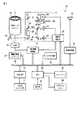
図1は、本実施形態に係るデータプロジェクタ装置10が備える電子回路の概略機能構成を示すブロック図である。
11は入出力コネクタ部であり、例えばピンジャック(RCA)タイプのビデオ入力端子、D−sub15タイプのRGB入力端子、及びUSB(Universal Serial Bus)コネクタを含む。FIG. 1 is a block diagram illustrating a schematic functional configuration of an electronic circuit included in the
An input /
入出力コネクタ部11より入力される各種規格の画像信号は、入出力インタフェース(I/F)12、システムバスSBを介し、一般にスケーラとも称される画像変換部13に入力される。 Image signals of various standards input from the input /
画像変換部13は、入力された画像信号を投影に適した所定のフォーマットの画像信号に統一し、適宜表示用のバッファメモリであるビデオRAM14に記憶した後に、投影画像処理部15へ送る。 The
この際、OSD(On Screen Display)用の各種動作状態を示すシンボル等のデータも必要に応じてビデオRAM14で画像信号に重畳加工され、加工後の画像信号が投影画像処理部15へ送られる。 At this time, data such as symbols indicating various operation states for OSD (On Screen Display) is also superimposed on the image signal by the
投影画像処理部15は、送られてきた画像信号に応じて、所定のフォーマットに従ったフレームレート、例えば120[フレーム/秒]と色成分の分割数、及び表示階調数を乗算した、より高速な時分割駆動により、空間的光変調素子(SLM)であるマイクロミラー素子16を表示駆動する。 The projection
このマイクロミラー素子16は、アレイ状に配列された複数、例えばXGA(横1024画素×縦768画素)分の微小ミラーの各傾斜角度を個々に高速でオン/オフ動作することでその反射光により光像を形成する。 The
一方で、光源部17から時分割でR,G,Bの原色光が循環的に出射される。この光源部17からの原色光が、ミラー18で全反射して上記マイクロミラー素子16に照射される。 On the other hand, R, G, B primary color lights are emitted cyclically from the
そして、マイクロミラー素子16での反射光で光像が形成され、形成された光像が投影レンズユニット19を介して、投影対象となる図示しないスクリーンに投影表示される。 Then, an optical image is formed by the reflected light from the
光源部17は、具体的な光学構成については後述するが、2種類の光源、すなわち青色のレーザ光を発する半導体レーザ20と、赤色光を発するLED21とを有する。 Although the specific optical configuration will be described later, the
半導体レーザ20の発する青色のレーザ光は、ミラー22で全反射された後、ダイクロイックミラー23を透過して、カラーホイール24の周上の1点に照射される。このカラーホイール24は、モータ25により回転される。カラーホイール24のレーザ光が照射される周上には、緑色蛍光反射板と青色用拡散板とが合わせてリング状となるように形成されている。 The blue laser light emitted from the
カラーホイール24の緑色蛍光反射板がレーザ光の照射位置にある場合、レーザ光の照射により緑色光が励起され、励起された緑色光がカラーホイール24で反射された後、ダイクロイックミラー23でも反射される。その後、この緑色光は、さらにダイクロイックミラー28で反射され、インテグレータ29で輝度分布が略均一な光束とされた後にミラー30で全反射されて、上記ミラー18へ送られる。 When the green fluorescent reflector of the
また、該拡散板がレーザ光の照射位置にある場合、レーザ光は該拡散板で拡散されながらカラーホイール24を透過した後、ミラー26,27でそれぞれ全反射される。その後、この青色光は、ダイクロイックミラー28を透過し、インテグレータ29で輝度分布が略均一な光束とされた後にミラー30で全反射されて、上記ミラー18へ送られる。 When the diffuser plate is at the laser beam irradiation position, the laser beam is transmitted through the
さらに、上記LED21の発した赤色光は、ダイクロイックミラー23を透過した後にダイクロイックミラー28で反射され、インテグレータ29で輝度分布が略均一な光束とされた後にミラー30で全反射されて、上記ミラー18へ送られる。 Further, the red light emitted from the
以上の如く、ダイクロイックミラー23は、青色光、及び赤色光を透過する一方で、緑色光を反射する分光特性を有する。 As described above, the
また、ダイクロイックミラー28は、青色光を透過する一方で、赤色光、及び緑色光を反射する分光特性を有する。 The
光源部17の半導体レーザ20とLED21の各発光タイミング、及びモータ25によるカラーホイール24の回転を投影光処理部31が統括して制御する。投影光処理部31は、投影画像処理部15から与えられる画像データのタイミングに応じて半導体レーザ20、LED21の各発光タイミングとカラーホイール24の回転を制御する。 The projection
上記各回路の動作すべてをCPU32が制御する。このCPU32は、DRAMで構成されたメインメモリ33、及び動作プログラムや各種定型データ等を記憶した電気的書換可能な不揮発性メモリでなるプログラムメモリ34を用いて、このデータプロジェクタ装置10内の制御動作を実行する。 The
上記CPU32は、操作部35からのキー操作信号に応じて各種投影動作を実行する。
この操作部35は、データプロジェクタ装置10の本体に設けられるキー操作部と、このデータプロジェクタ装置10専用の図示しないリモートコントローラの間で赤外光を受光するレーザ受光部とを含み、ユーザが本体のキー操作部またはリモートコントローラで操作したキーに基づくキー操作信号をCPU32へ直接出力する。The
The
操作部35は、上記キー操作部、及びリモートコントローラ共に、例えばフォーカス調整キー、ズーム調整キー、入力切換キー、メニューキー、カーソル(←,→,↑,↓)キー、セットキー、キャンセルキー等を備えるものとする。 The
上記CPU32はさらに、上記システムバスSBを介して音声処理部36とも接続される。音声処理部36は、PCM音源等の音源回路を備え、投影動作時に与えられる音声データをアナログ化し、スピーカ部37を駆動して拡声放音させ、あるいは必要によりビープ音等を発生させる。 The
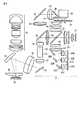
次に、図2により主として光源部17の具体的な光学系の構成例を示す。同図は、上記光源部17の構成を平面的なレイアウトで表現したものである。 Next, FIG. 2 mainly shows a specific optical system configuration example of the
ここでは、同一の発光特性を有する複数、例えば3つの半導体レーザ20A〜20Cを設け、これら半導体レーザ20A〜20Cはいずれも青色、例えば波長450[nm]のレーザ光を発振する。 Here, a plurality of, for example, three
これら半導体レーザ20A〜20Cの発振した青色光は、レンズ41A〜41Cを介してミラー22A〜22Cで全反射され、さらにレンズ42,43を介した後に上記ダイクロイックミラー23を透過し、レンズ群44を介してカラーホイール24に照射される。 The blue light oscillated by the
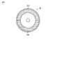
図3は、本実施形態におけるカラーホイール24の構成を示す。同図に示すようにカラーホイール24上では、ともに中心角180°の半円リング状の緑色蛍光体反射板24Gと青色用拡散板24Bとが合わせて1つのリングを形成する。 FIG. 3 shows a configuration of the
カラーホイール24の緑色蛍光体反射板24Gが青色光の照射位置にある場合、その照射により例えば波長約530[nm]を中心とした波長帯の緑色光が励起され、励起された緑色光がカラーホイール24で反射された後、レンズ群44を介してダイクロイックミラー23でも反射される。 When the
ダイクロイックミラー23で反射した緑色光は、レンズ45を介してさらにダイクロイックミラー28で反射され、レンズ46を介してインテグレータ29で輝度分布が略均一な光束とされた後にレンズ47を介し、ミラー30で全反射されて、レンズ48を介して上記ミラー18へ送られる。 The green light reflected by the
ミラー18で全反射した緑色光は、レンズ49を介してマイクロミラー素子16に照射される。そして、その緑色光の反射光で緑色成分の光像が形成され、レンズ49、上記投影レンズユニット19を介して外部へ投射される。 The green light totally reflected by the
また、カラーホイール24の青色用拡散板24Bが青色光の照射位置にある場合、青色光は該拡散板24Bで拡散されながらカラーホイール24を透過し、背面側にあるレンズ50を介してミラー26で全反射される。 Further, when the
さらに青色光は、レンズ51を介してミラー27で全反射され、レンズ52を介した後に上記ダイクロイックミラー28を透過し、レンズ46を介してインテグレータ29で輝度分布が略均一な光束とされた後にレンズ47を介し、ミラー30で全反射されて、レンズ48を介して上記ミラー18へ送られる。 Further, the blue light is totally reflected by the
一方、上記LED21は、例えば波長620[nm]の赤色光を発生する。LED21の発した赤色光は、レンズ群53を介し、上記ダイクロイックミラー23を透過した後にレンズ45を介して上記ダイクロイックミラー28で反射され、さらにレンズ46を介してインテグレータ29で輝度分布が略均一な光束とされた後にレンズ47を介し、ミラー30で全反射されて、レンズ48を介して上記ミラー18へ送られる。 On the other hand, the
次に上記実施形態の動作について説明する。
ここでは、投影するカラー画像1フレームを構成するR,G,Bの各原色画像の時間比を1:1:1とする。すなわち、カラーホイール24の1回転360°に対して、R,G,Bの各原色画像を投影する時間比r:g:bは、カラーホイール24の中心角度に置換すると120°:120°:120°となる。Next, the operation of the above embodiment will be described.
Here, the time ratio of the R, G, B primary color images constituting one frame of the color image to be projected is 1: 1: 1. That is, with respect to one rotation 360 ° of the
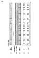
図4(A)は、従来の一般的な駆動方法におけるカラーホイールの駆動タイミングを参照のために示す。従来の一般的なカラーホイールでは、1フレームでR,G,Bの各セグメントが一巡するように制御される。 FIG. 4A shows the driving timing of the color wheel in the conventional general driving method for reference. In the conventional general color wheel, the R, G, and B segments are controlled to make a round in one frame.
一方、本実施形態では、上記図3で示した如くカラーホイール24が緑色蛍光体反射板24Gと青色用拡散板24Bとで円周を二分するように構成されているため、図4(B)に示すようにこれら2つのセグメント1回転で1フレームに同期するように制御する。 On the other hand, in the present embodiment, as shown in FIG. 3, the
半導体レーザ20A〜20Cからの青色のレーザ光の光路中にカラーホイール24の緑色蛍光体反射板24Gが存在する前半1/2フレームの期間を3等分し、各等分期間において当初の1/3期間にLED21を点灯駆動して赤色光を発生させるものとする。 The period of the first half frame in which the
このとき、LED21の点灯と同期して、半導体レーザ20A〜20Cでは青色のレーザ光の発振を停止する。 At this time, in synchronization with the lighting of the
同様に、半導体レーザ20A〜20Cからの青色のレーザ光の光路中にカラーホイール24の青色用拡散板24Bが存在する後半1/2フレームの期間も3等分し、各等分期間において当初の1/3期間にLED21を点灯駆動して赤色光を発生させるものとする。 Similarly, the period of the latter half frame in which the
このとき、LED21の点灯と同期して、半導体レーザ20A〜20Cでは青色のレーザ光の発振を停止する。 At this time, in synchronization with the lighting of the
以上、半導体レーザ20A〜20Cが青色のレーザ光を発振するタイミングを図4(D)に、LED21が赤色光を発生するタイミングを図4(E)に示す。 The timing at which the
したがって、光源部17としてマイクロミラー素子16に照射されるR,G,B原色光の切替パターンは図4(C)に示すようなものとなる。 Therefore, the switching pattern of R, G, B primary color light irradiated to the
このように、カラーホイール24のセグメントの構成に合わせて半導体レーザ20A〜20Cから青色のレーザ光を発振して青色光及び緑色光を発生させるのに割り込むようにして、LED21の点灯による赤色光をより高い周波数、例えば青色光及び緑色光の6倍の周波数となるように期間を分割して配置するものとした。 As described above, the blue light from the
この場合、カラーホイール24の中心角に換算すると、赤色光の点灯期間は20°×6で120°、緑色光の点灯期間は40°×3で120°、同じく青色の点灯期間も40°×3で120°となり、1フレーム360°をR,G,Bそれぞれで3等分して120°ずつとしている。 In this case, when converted to the central angle of the
上記のように、光源である半導体レーザ20A〜20Cからの光軸中にカラーホイール24の緑色蛍光体反射板24Gがある期間に対し、該期間中に半導体レーザ20A〜20Cの発振を一時的に停止してLED21を点灯させ、赤色光による画像をマイクロミラー素子16で形成して投影させる期間Grのデューティ比は、カラーホイール24の1回転360°に対するR,G,Bの各原色画像を投影する時間比r:g:bを用いて
Gr=r/(r+g+b)
で与えられる。As described above, for the period in which the
Gr = r / (r + g + b)
Given in.
これに対して、半導体レーザ20A〜20Cからの光軸中にカラーホイール24の緑色蛍光体反射板24Gがある期間に対し、LED21の点灯を一時的に停止して半導体レーザ20A〜20Cを発振させ、反射光である緑色光による画像をマイクロミラー素子16で形成して投影させる期間Ggのデューティ比は、
Gg=(g+b)/(r+g+b)
で与えられる。In contrast, during the period in which the
Gg = (g + b) / (r + g + b)
Given in.
同様に、光源である半導体レーザ20A〜20Cからの光軸中にカラーホイール24の青色用拡散板24Bがある期間に対し、該期間中に半導体レーザ20A〜20Cの発振を一時的に停止してLED21を点灯させ、赤色光による画像をマイクロミラー素子16で形成して投影させる期間Brのデューティ比は、
Br=r/(r+g+b)
で与えられる。Similarly, for the period in which the
Br = r / (r + g + b)
Given in.
これに対して、半導体レーザ20A〜20Cからの光軸中にカラーホイール24の青色用拡散板24Bがある期間に対し、LED21の点灯を一時的に停止して半導体レーザ20A〜20Cを発振させ、透過光である青色光による画像をマイクロミラー素子16で形成して投影させる期間Bbのデューティ比は、
Bb=(g+b)/(r+g+b)
で与えられる。On the other hand, during the period in which the
Bb = (g + b) / (r + g + b)
Given in.
赤色光を発生するLED21は、連続点灯による温度上昇で熱抵抗値の上昇に伴い発光効率が低下することが知られており、上記のように発光期間を分割して高周波数駆動とすることにより発光効率の低下を回避して安定した輝度での発光を実現できる。 It is known that the
また、LED21ほどではないものの、半導体レーザ20A〜20Cも同様に連続発振による温度上昇で発光効率が多少低下することが知られており、上記のように発光期間を分割して高周波数駆動とすることにより、やはり発光効率の低下を回避して安定した輝度での発光を実現できる。 In addition, although not as much as the
このような光源部17での発光駆動に同期して、マイクロミラー素子16では各原色画像毎の階調駆動を実行する。 In synchronism with the light emission driving in the
以上詳記した如く本実施形態によれば、レーザ光の励起で発光する赤色蛍光体の発光輝度が他の色に比して低いことに鑑み、単一の光源として青色光を発振する半導体レーザ20A〜20Cで得られる原色成分毎の輝度が不揃いである場合に他の光源として赤色光を発生するLED21を用いてそれを補償するとともに、各光源毎の発光特性を考慮して光周波数駆動することで発光効率を上げて動作を安定化し、結果として色再現性と投影画像の明るさを両立することが可能となる。 As described above in detail, according to the present embodiment, a semiconductor laser that oscillates blue light as a single light source in light of the fact that the emission luminance of a red phosphor that emits light by excitation of laser light is lower than other colors. When the luminance for each primary color component obtained in 20A to 20C is uneven, the
また上記実施形態では、カラーホイール24を用いることに起因するカラーブレーキング現象(色割れ現象)に関しても、カラーホイール24を介さずに赤色光を発生するLED21の点灯タイミングをカラーホイール24の緑色蛍光体反射板24Gと青色用拡散板24Bの切替タイミングに同期させるものとしたので、カラーブレーキング現象の発生を確実に抑制して、画質が低下するのを回避できる。 Further, in the above-described embodiment, regarding the color braking phenomenon (color breaking phenomenon) caused by using the
さらに、上記実施形態では、カラーホイール24の緑色蛍光体反射板24Gと青色用拡散板24Bの期間が同一の時間比であったため、これらの期間に割り込むLED21の発光期間も緑色蛍光体反射板24Gの期間と青色用拡散板24Bの期間で同一のタイミングパターンとなるように配置したので、1フレーム中におけるR,G,Bの各期間の時間比を適正に維持できる。 Furthermore, in the above embodiment, the period of the
(変形例)
次に、カラーホイール24の他の構成例についても説明する。
図5は、上記カラーホイール24とは異なるカラーホイール24′の構成を示す。同図に示すようにカラーホイール24′上では、緑色蛍光体反射板24Gが中心角240°、青色用拡散板24Bが中心角120°となって、緑色蛍光体反射板24Gと青色用拡散板24Bの比が2:1となるような1つのリングを形成している。(Modification)
Next, another configuration example of the
FIG. 5 shows a configuration of a
半導体レーザ20A〜20Cの発振する青色のレーザ光の波長、この青色のレーザ光が照射された場合にカラーホイール24′の緑色蛍光体反射板24Gから励起される緑色光の波長、及びLED21の発生する赤色光の波長については上記と同様であるものとする。 The wavelength of the blue laser light oscillated by the
上記カラーホイール24′を用いる場合の動作について説明する。
ここでは、投影するカラー画像1フレームを構成するR,G,Bの各原色画像の時間比を1:2:1とする。すなわち、カラーホイール24の1回転360°に対して、R,G,Bの各原色画像を投影する時間比は、カラーホイール24の中心角度に置換すると90°:180°:90°となる。The operation when the color wheel 24 'is used will be described.
Here, the time ratio of the R, G, B primary color images constituting one frame of the color image to be projected is 1: 2: 1. That is, the time ratio for projecting the R, G, and B primary color images with respect to one rotation of 360 ° of the
図6(A)は、従来の一般的な駆動方法におけるカラーホイールの駆動タイミングを参照のために示す。従来の一般的なカラーホイールでは、1フレームでR,G,Bの各セグメントが一巡するように制御される。 FIG. 6A shows the driving timing of the color wheel in the conventional general driving method for reference. In the conventional general color wheel, the R, G, and B segments are controlled to make a round in one frame.
一方、本実施形態では、上記図5で示した如くカラーホイール24′が緑色蛍光体反射板24Gと青色用拡散板24Bとで比率は異なるが円周を二分するように構成されているため、図6(B)に示すようにこれら2つのセグメント1回転で1フレームに同期するように制御する。 On the other hand, in the present embodiment, as shown in FIG. 5, the color wheel 24 'is configured to bisect the circumference although the ratio is different between the
半導体レーザ20A〜20Cからの青色のレーザ光の光路中にカラーホイール24′の緑色蛍光体反射板24Gが存在する前半2/3フレームの期間を3等分し、各等分期間において当初の1/3期間にLED21を点灯駆動して赤色光を発生させるものとする。 The first 2/3 frame period in which the green
このとき、LED21の点灯と同期して、半導体レーザ20A〜20Cでは青色のレーザ光の発振を停止する。 At this time, in synchronization with the lighting of the
同様に、半導体レーザ20A〜20Cからの青色のレーザ光の光路中にカラーホイール24′の青色用拡散板24Bが存在する後半1/3フレームの期間も3等分し、各等分期間において当初の1/3期間にLED21を点灯駆動して赤色光を発生させるものとする。 Similarly, the period of the last 1/3 frame in which the
このとき、LED21の点灯と同期して、半導体レーザ20A〜20Cでは青色のレーザ光の発振を停止する。 At this time, in synchronization with the lighting of the
以上、半導体レーザ20A〜20Cが青色のレーザ光を発振するタイミングを図6(D)に、LED21が赤色光を発生するタイミングを図6(E)に示す。 The timing at which the
したがって、光源部17としてマイクロミラー素子16に照射されるR,G,B原色光の切替パターンは図6(C)に示すようなものとなる。 Therefore, the switching pattern of the R, G, B primary color light irradiated to the
このように、カラーホイール24のセグメントの構成に合わせて半導体レーザ20A〜20Cから青色のレーザ光を発振して青色光及び緑色光を発生させるのに割り込むようにして、LED21の点灯による赤色光をより高い周波数、例えば青色光及び緑色光の6倍の周波数となるように期間を分割して配置するものとした。 As described above, the blue light from the
この場合、カラーホイール24′の中心角に換算すると、赤色光の点灯期間は20°×3+10×3で90°、緑色光の点灯期間は60°×3で180°、青色の点灯期間は30°×3で90°となり、1フレーム360°をR,G,Bで1:2:1の比で分割している。 In this case, when converted to the central angle of the
このような光源部17での発光駆動に同期して、マイクロミラー素子16では各原色画像毎の階調駆動を実行する。 In synchronism with the light emission driving in the
このように上記実施形態の変形例では、カラーホイール24の緑色蛍光体反射板24Gと青色用拡散板24Bの期間が異なる時間比であったため、これらの期間に割り込むLED21の発光期間も緑色蛍光体反射板24Gの期間と青色用拡散板24Bの期間で同一の比で異なるタイミングパターンとなるように配置したので、結果として1フレーム中におけるR,G,Bの各期間の時間比を適正に維持できる。 As described above, in the modification of the above embodiment, the periods of the
なお、上記実施形態は、半導体レーザ20A〜20Cで青色のレーザ光を発振してカラーホイール24(24′)により青色光及び緑色光を発生させる一方で、LED21で赤色光を発生するものとして説明したが、本発明はこれに限らず、1つの光源で発生しうる原色光の輝度が不揃いである場合に、他の光源を用いてそれを補償するような、複数種類の光源を用いる光源部、及びそのような光源部を用いる投影装置であれば同様に適用可能である。 In the above embodiment, the
また、上記実施形態は本発明をDLP(登録商標)方式のデータプロジェクタ装置に適用した場合について説明したものであるが、例えば透過型のモノクロ液晶パネルを用いて光像を形成する液晶プロジェクタにも同様に本発明を適用することができる。 In the above embodiment, the present invention is applied to a DLP (registered trademark) type data projector apparatus. For example, a liquid crystal projector that forms a light image using a transmission type monochrome liquid crystal panel is also described. Similarly, the present invention can be applied.
その他、本発明は上述した実施形態に限定されるものではなく、実施段階ではその要旨を逸脱しない範囲で種々に変形することが可能である。また、上述した実施形態で実行される機能は可能な限り適宜組み合わせて実施しても良い。上述した実施形態には種々の段階が含まれており、開示される複数の構成要件による適宜の組み合せにより種々の発明が抽出され得る。例えば、実施形態に示される全構成要件からいくつかの構成要件が削除されても、効果が得られるのであれば、この構成要件が削除された構成が発明として抽出され得る。 In addition, the present invention is not limited to the above-described embodiments, and various modifications can be made without departing from the scope of the invention in the implementation stage. Further, the functions executed in the above-described embodiments may be combined as appropriate as possible. The above-described embodiment includes various stages, and various inventions can be extracted by an appropriate combination of a plurality of disclosed constituent elements. For example, even if some constituent requirements are deleted from all the constituent requirements shown in the embodiment, if the effect is obtained, a configuration from which the constituent requirements are deleted can be extracted as an invention.
10…データプロジェクタ装置、11…入出力コネクタ部、12…入出力インタフェース(I/F)、13…画像変換部(スケーラ)、14…ビデオRAM、15…投影画像処理部、16…マイクロミラー素子(SLM)、17…光源部、18…ミラー、19…投影レンズユニット、20…(B発光)半導体レーザ、21…(R発光)LED、22…ミラー、23…ダイクロイックミラー、24,24′…カラーホイール、24B…青色用拡散板、24G…緑色蛍光体反射板、25…モータ(M)、26,27…ミラー、28…ダイクロイックミラー、29…インテグレータ、30…ミラー、31…投影光処理部、32…CPU、33…メインメモリ、34…プログラムメモリ、35…操作部、36…音声処理部、37…スピーカ部、41A〜41C,42,43…レンズ、44…レンズ群、45〜52…レンズ、53…レンズ群、SB…システムバス。 DESCRIPTION OF
Claims (7)
Translated fromJapanese上記第1の光源の発光を用いて時分割で複数色の光源光を発生する光源光発生手段と、
上記第1の波長帯域とは異なる第2の波長帯域で発光する第2の光源と、
上記複数色の光源光それぞれの発生期間において、上記光源光発生手段の時分割周波数に対応して、該時分割周波数よりも大きい周波数で、上記第2の光源の発光を用いた光源光を上記光源光発生手段で発生する上記複数色の光源光に均等間隔で割り込むように上記第1及び第2の各光源の駆動タイミングを制御する光源制御手段と
を具備したことを特徴とする光源装置。A first light source that emits light in a first wavelength band;
Light source light generating means for generating light sources of a plurality of colors in a time-sharing manner using light emitted from the first light source;
A second light source that emits light in a second wavelength band different from the first wavelength band;
Corresponding to the time division frequency of the light source light generating means, the light source light using the light emission of the second light source at a frequency larger than the time division frequency in the generation period of the light sources of the plurality of colors A light source device comprising: light source control means for controlling the drive timing of the first and second light sources so as to interrupt the light sources of the plurality of colors generated by the light source light generation means at equal intervals.
上記第1の光源の発光を用いて時分割で複数色の光源光を発生する光源光発生手段と、
上記第1の波長帯域とは異なる第2の波長帯域で発光する第2の光源と、
上記複数色の光源光それぞれの発生期間において、上記光源光発生手段の時分割周波数に対応して、該時分割周波数よりも大きい周波数で、上記第2の光源の発光を用いた光源光を上記光源光発生手段で発生する上記複数色の光源光に均等間隔で割り込むように上記第1及び第2の各光源の駆動タイミングを制御する光源制御手段と、
画像信号を入力する入力手段と、
上記光源制御手段による制御に基づいて出射される光源光を用い、上記入力手段で入力する画像信号に対応したカラーの光像を形成して投影する投影手段と
を具備したことを特徴とする投影装置。A first light source that emits light in a first wavelength band;
Light source light generating means for generating light sources of a plurality of colors in a time-sharing manner using light emitted from the first light source;
A second light source that emits light in a second wavelength band different from the first wavelength band;
Corresponding to the time division frequency of the light source light generating means, the light source light using the light emission of the second light source at a frequency larger than the time division frequency in the generation period of the light sources of the plurality of colors Light source control means for controlling the drive timing of each of the first and second light sources so as to interrupt the plurality of color light source lights generated by the light source light generation means at equal intervals;
An input means for inputting an image signal;
Projection means comprising: projection means for forming and projecting a color light image corresponding to an image signal input by the input means using light source light emitted based on control by the light source control means. apparatus.
上記光源制御手段は、上記光源光発生手段の上記カラーホイールに形成した波長変換物質が上記カラーホイールの回転により切替る切替タイミングに同期して上記第2の光源の発光を用いた光源光が割り込むように上記第1及び第2の各光源の駆動タイミングを制御することを特徴とする請求項3または4記載の投影装置。The light source light generating means uses a color wheel in which a wavelength conversion material that converts the wavelength band of the emitted light by transmitting or reflecting the emitted light from the first light source is formed at least on a part of the circumference.
The light source control means interrupts light source light using light emitted from the second light source in synchronization with a switching timing at which a wavelength conversion material formed on the color wheel of the light source light generating means isswitched by rotation of the color wheel. 5. The projection apparatus according to claim 3, wherein the drive timing of each of the first and second light sources is controlled as described above.
上記複数色の光源光それぞれの発生期間において、上記光源光発生部の時分割周波数に対応して、該時分割周波数よりも大きい周波数で、上記第2の光源の発光を用いた光源光を上記光源光発生部で発生する上記複数色の光源光に均等間隔で割り込むように上記第1及び第2の各光源の駆動タイミングを制御する光源制御工程を有したことを特徴とする投影方法。A first light source that emits light in a first wavelength band, a light source light generator that generates light of a plurality of colors in a time-sharing manner using light emitted from the first light source, and a second light source that is different from the first wavelength band. A second light source that emits light in the wavelength band, an input unit that inputs an image signal, and a projection unit that forms and projects a color light image corresponding to the image signal input from the input unit using light source light. A projection method using a projection apparatus,
In the generation period of each of the light sources of the plurality of colors, the light source light using the light emission of the second light source at a frequency larger than the time division frequency corresponding to the time division frequency of the light source light generation unit A projection method, comprising: a light source control step of controlling driving timings of the first and second light sources so as to interrupt the light sources of the plurality of colors generated at a light source light generator at equal intervals.
Priority Applications (8)
| Application Number | Priority Date | Filing Date | Title |
|---|---|---|---|
| JP2009156092AJP5412996B2 (en) | 2009-06-30 | 2009-06-30 | Light source device, projection device, and projection method |
| TW099121139ATWI439726B (en) | 2009-06-30 | 2010-06-29 | Light source device, projection apparatus, and projection method |
| US12/825,615US8398247B2 (en) | 2009-06-30 | 2010-06-29 | Light source device having first light source, second light source, and control section to control drive timing of first light source and second light source such that drive pattern of second light source is inversion of drive pattern of second light source, and projection apparatus and projection method which utilize said light source device |
| CN2010102212143ACN101937165B (en) | 2009-06-30 | 2010-06-30 | Light source device, projection device and projection method |
| KR1020100062572AKR20110001975A (en) | 2009-06-30 | 2010-06-30 | Light source device, projection device and projection method |
| CN2012102433997ACN102799056A (en) | 2009-06-30 | 2010-06-30 | Light source device, projection apparatus, and projection method |
| KR1020120110571AKR101578829B1 (en) | 2009-06-30 | 2012-10-05 | Light source device, projection apparatus, and projection method |
| US13/766,610US8641205B2 (en) | 2009-06-30 | 2013-02-13 | Light source device having first light source, second light source, and control section to control drive timing of first light source and second light source such that drive pattern of second light source is inversion of drive pattern of first light source, and projection apparatus and projection method which utilize said light source device |
Applications Claiming Priority (1)
| Application Number | Priority Date | Filing Date | Title |
|---|---|---|---|
| JP2009156092AJP5412996B2 (en) | 2009-06-30 | 2009-06-30 | Light source device, projection device, and projection method |
Publications (2)
| Publication Number | Publication Date |
|---|---|
| JP2011013371A JP2011013371A (en) | 2011-01-20 |
| JP5412996B2true JP5412996B2 (en) | 2014-02-12 |
Family
ID=43380345
Family Applications (1)
| Application Number | Title | Priority Date | Filing Date |
|---|---|---|---|
| JP2009156092AActiveJP5412996B2 (en) | 2009-06-30 | 2009-06-30 | Light source device, projection device, and projection method |
Country Status (5)
| Country | Link |
|---|---|
| US (2) | US8398247B2 (en) |
| JP (1) | JP5412996B2 (en) |
| KR (2) | KR20110001975A (en) |
| CN (2) | CN101937165B (en) |
| TW (1) | TWI439726B (en) |
Families Citing this family (55)
| Publication number | Priority date | Publication date | Assignee | Title |
|---|---|---|---|---|
| JP5412996B2 (en)* | 2009-06-30 | 2014-02-12 | カシオ計算機株式会社 | Light source device, projection device, and projection method |
| WO2011092841A1 (en) | 2010-01-29 | 2011-08-04 | Necディスプレイソリューションズ株式会社 | Illumination optical system and projector using same |
| US8496352B2 (en) | 2010-02-26 | 2013-07-30 | Texas Instruments Incorporated | Wavelength conversion |
| CN202040748U (en)* | 2011-03-08 | 2011-11-16 | 绎立锐光科技开发(深圳)有限公司 | Optical Wavelength Conversion Wheel Assembly |
| US9287684B2 (en) | 2011-04-04 | 2016-03-15 | Soraa Laser Diode, Inc. | Laser package having multiple emitters with color wheel |
| JP5914878B2 (en)* | 2011-04-20 | 2016-05-11 | パナソニックIpマネジメント株式会社 | Light source device and projection display device |
| JP5987368B2 (en)* | 2011-07-05 | 2016-09-07 | 株式会社リコー | Illumination device and projection device |
| JP5936056B2 (en)* | 2011-07-28 | 2016-06-15 | カシオ計算機株式会社 | Rotating wheel, light source device, projector, and manufacturing method of rotating wheel |
| US9612511B2 (en)* | 2011-08-25 | 2017-04-04 | Appotronics Corporation Limited | Projection system using excitable wavelength conversion material in the light source |
| US10688527B2 (en) | 2011-09-22 | 2020-06-23 | Delta Electronics, Inc. | Phosphor device comprising plural phosphor agents for converting waveband light into plural color lights with different wavelength peaks |
| TWI448806B (en) | 2011-09-22 | 2014-08-11 | Delta Electronics Inc | Phosphor device and illumination system and projection equipment with the same |
| US10310363B2 (en) | 2011-09-22 | 2019-06-04 | Delta Electronics, Inc. | Phosphor device with spectrum of converted light comprising at least a color light |
| JP2013072888A (en)* | 2011-09-26 | 2013-04-22 | Sanyo Electric Co Ltd | Projection type image displaying apparatus |
| JP5862938B2 (en)* | 2011-10-03 | 2016-02-16 | カシオ計算機株式会社 | Light source device and projector |
| US9195123B2 (en) | 2011-10-13 | 2015-11-24 | Texas Instruments Corporated | Projector light source and system, including configuration for display of 3D images |
| JP5494610B2 (en)* | 2011-10-17 | 2014-05-21 | カシオ計算機株式会社 | Projection apparatus, projection control method, and program |
| TWI442165B (en)* | 2011-10-26 | 2014-06-21 | Hon Hai Prec Ind Co Ltd | Optical mechanical of porjector |
| TWI460525B (en)* | 2011-12-29 | 2014-11-11 | Hon Hai Prec Ind Co Ltd | Color wheel apparatus of porjector |
| DK177371B1 (en) | 2012-02-14 | 2013-02-25 | Martin Professional As | Animation and gobo forming means for illumination device |
| TWI440957B (en)* | 2012-03-09 | 2014-06-11 | Delta Electronics Inc | Illumination system for projection device |
| EP2867728B1 (en) | 2012-07-01 | 2017-05-03 | Barco NV | Projector optics |
| TW201405048A (en)* | 2012-07-19 | 2014-02-01 | 瓦維安股份有限公司 | Phosphor-based lamps for projection display |
| JP6064455B2 (en) | 2012-09-04 | 2017-01-25 | カシオ計算機株式会社 | Projection apparatus, projection method, and program |
| WO2014141272A2 (en)* | 2013-03-14 | 2014-09-18 | Stratasys Ltd. | Enhanced resolution dlp projector apparatus and method of using same |
| CN104765240B (en)* | 2014-01-03 | 2019-02-19 | 深圳市亿思达科技集团有限公司 | A kind of double laser light source system |
| CN104765238B (en)* | 2014-01-03 | 2018-09-25 | 深圳市亿思达科技集团有限公司 | A kind of double laser light source system |
| JP6287437B2 (en)* | 2014-03-26 | 2018-03-07 | セイコーエプソン株式会社 | projector |
| CN105025279B (en)* | 2014-04-24 | 2017-03-01 | 深圳市绎立锐光科技开发有限公司 | A kind of light-source system and projection display equipment |
| US10732495B2 (en) | 2014-05-02 | 2020-08-04 | Coretronic Corporation | Illumination system, projection apparatus and method for driving illumination system |
| TWI504832B (en)* | 2014-05-02 | 2015-10-21 | Coretronic Corp | Illumination system and projection apparatus |
| CN105093787B (en)* | 2014-05-15 | 2017-02-22 | 光宝电子(广州)有限公司 | Light source driving method and apparatus used for image projection. |
| CN105282902A (en)* | 2014-06-20 | 2016-01-27 | 宁波舜宇光电信息有限公司 | Led light source control method |
| JP6432765B2 (en)* | 2014-09-08 | 2018-12-05 | カシオ計算機株式会社 | Light source device and projector |
| CN105988272B (en)* | 2015-02-15 | 2019-03-01 | 深圳光峰科技股份有限公司 | Optical projection system and its control method |
| WO2016157365A1 (en)* | 2015-03-30 | 2016-10-06 | Necディスプレイソリューションズ株式会社 | Projector and image light projection method |
| CN106200229B (en)* | 2015-05-04 | 2019-01-08 | 深圳市光峰光电技术有限公司 | Splicing display device and tiled display control method |
| CN104786509B (en)* | 2015-05-15 | 2018-09-04 | 京东方科技集团股份有限公司 | 3D printer and its projection arrangement |
| JP6816352B2 (en)* | 2015-10-08 | 2021-01-20 | 株式会社リコー | Projectors, projection systems and programs |
| CN105652574B (en)* | 2016-03-29 | 2017-07-25 | 海信集团有限公司 | Colour wheel synchronisation control means and device in a kind of laser projection device |
| CN105892213B (en)* | 2016-06-30 | 2017-08-25 | 海信集团有限公司 | A kind of two-color laser light source drive control circuit |
| US10260188B2 (en)* | 2016-07-18 | 2019-04-16 | Haier Us Appliance Solutions, Inc. | Appliance user interface and method of operation |
| CN108279548B (en)* | 2017-01-06 | 2021-02-02 | 深圳光峰科技股份有限公司 | Projection system |
| CN108303842B (en)* | 2017-01-12 | 2020-09-15 | 深圳光峰科技股份有限公司 | Projection Display System |
| CN108663879B (en) | 2017-03-31 | 2021-04-06 | 中强光电股份有限公司 | Projector and illumination system thereof |
| CN106933015B (en)* | 2017-04-17 | 2019-04-26 | 苏州佳世达光电有限公司 | The control method of projection arrangement and projection arrangement |
| US10634982B2 (en)* | 2017-09-01 | 2020-04-28 | Panasonic Intellectual Property Management Co., Ltd. | Light source device and projection display apparatus |
| CN109634036B (en) | 2017-10-09 | 2022-02-18 | 中强光电股份有限公司 | Projection device and illumination system thereof |
| CN110045571B (en)* | 2018-01-16 | 2022-05-24 | 中强光电股份有限公司 | Light source generating device, projection device and light source generating method thereof |
| CN108628075B (en)* | 2018-05-08 | 2021-03-12 | 青岛海信激光显示股份有限公司 | Light source device, control method of light source device and projection equipment |
| CN108957931B (en)* | 2018-06-29 | 2020-11-03 | 海信视像科技股份有限公司 | White balance adjusting method of laser light source and laser projection equipment |
| CN110703552B (en) | 2018-07-10 | 2021-10-15 | 中强光电股份有限公司 | Lighting system and projection device |
| JP6960093B2 (en)* | 2019-04-10 | 2021-11-05 | カシオ計算機株式会社 | Projection device, projection control device and program |
| CN111812931B (en)* | 2019-04-11 | 2022-04-12 | 卡西欧计算机株式会社 | Projection device, projection control method, and storage medium |
| CN113253554B (en)* | 2020-02-13 | 2022-11-08 | 中强光电股份有限公司 | Illumination system, illumination control method, and projection apparatus |
| JP7732314B2 (en)* | 2020-12-07 | 2025-09-02 | 株式会社リコー | Light source device and projection device |
Family Cites Families (22)
| Publication number | Priority date | Publication date | Assignee | Title |
|---|---|---|---|---|
| JP4247042B2 (en)* | 2003-05-12 | 2009-04-02 | 三菱電機株式会社 | Projection display |
| JP4829470B2 (en) | 2003-05-14 | 2011-12-07 | Necディスプレイソリューションズ株式会社 | Projection display |
| JP2005106951A (en)* | 2003-09-29 | 2005-04-21 | Seiko Epson Corp | Drive control of projector and light source lamp for projector |
| CN100489952C (en)* | 2004-01-28 | 2009-05-20 | 松下电器产业株式会社 | Light emitting method, light emitting device, projection type display device |
| KR100612011B1 (en)* | 2004-05-27 | 2006-08-11 | 삼성전자주식회사 | Method and apparatus for improving contrast of projection system |
| JP4415377B2 (en)* | 2004-06-24 | 2010-02-17 | セイコーエプソン株式会社 | Light source driving method and projector |
| JP2006017801A (en) | 2004-06-30 | 2006-01-19 | Olympus Corp | Light source device and image projecting device |
| JP2006023436A (en) | 2004-07-07 | 2006-01-26 | Olympus Corp | Illuminating apparatus and projector |
| JP4158761B2 (en)* | 2004-11-26 | 2008-10-01 | 株式会社ニコン | Projector device |
| CN100368864C (en)* | 2005-04-18 | 2008-02-13 | 精工爱普生株式会社 | Optical scanning device, its control method, and image display device |
| WO2006129515A1 (en)* | 2005-05-31 | 2006-12-07 | Matsushita Electric Industrial Co., Ltd. | Display device |
| WO2006133214A2 (en)* | 2005-06-07 | 2006-12-14 | Optical Research Associates | Phosphor wheel illuminator |
| JP2007047638A (en)* | 2005-08-12 | 2007-02-22 | Seiko Epson Corp | Image display device and light source device |
| JP2007156270A (en)* | 2005-12-07 | 2007-06-21 | Sharp Corp | Light source device and projection type image display device |
| JP2007218956A (en)* | 2006-02-14 | 2007-08-30 | Sharp Corp | Projection type image display device |
| JP4483881B2 (en)* | 2007-03-20 | 2010-06-16 | カシオ計算機株式会社 | Projection apparatus, projection control method, and program |
| US20080239248A1 (en)* | 2007-03-30 | 2008-10-02 | Kabushiki Kaisha Toshiba | Display illumination apparatus |
| JP2008261998A (en)* | 2007-04-11 | 2008-10-30 | Olympus Corp | Light source device and projector |
| EP2215846B1 (en)* | 2007-11-28 | 2020-03-18 | Signify Holding B.V. | Illumination system, method of driving a light source in an illumination system and computer program |
| JP4730428B2 (en)* | 2008-12-01 | 2011-07-20 | セイコーエプソン株式会社 | Discharge lamp driving method and driving device, light source device, and image display device |
| US8235532B2 (en)* | 2009-04-30 | 2012-08-07 | Texas Instruments Incorporated | Color splitting method for light sources |
| JP5412996B2 (en)* | 2009-06-30 | 2014-02-12 | カシオ計算機株式会社 | Light source device, projection device, and projection method |
- 2009
- 2009-06-30JPJP2009156092Apatent/JP5412996B2/enactiveActive
- 2010
- 2010-06-29USUS12/825,615patent/US8398247B2/ennot_activeExpired - Fee Related
- 2010-06-29TWTW099121139Apatent/TWI439726B/enactive
- 2010-06-30CNCN2010102212143Apatent/CN101937165B/enactiveActive
- 2010-06-30CNCN2012102433997Apatent/CN102799056A/enactivePending
- 2010-06-30KRKR1020100062572Apatent/KR20110001975A/ennot_activeCeased
- 2012
- 2012-10-05KRKR1020120110571Apatent/KR101578829B1/enactiveActive
- 2013
- 2013-02-13USUS13/766,610patent/US8641205B2/enactiveActive
Also Published As
| Publication number | Publication date |
|---|---|
| KR101578829B1 (en) | 2015-12-18 |
| JP2011013371A (en) | 2011-01-20 |
| US20100328626A1 (en) | 2010-12-30 |
| TW201109721A (en) | 2011-03-16 |
| TWI439726B (en) | 2014-06-01 |
| CN101937165A (en) | 2011-01-05 |
| US8398247B2 (en) | 2013-03-19 |
| CN102799056A (en) | 2012-11-28 |
| KR20110001975A (en) | 2011-01-06 |
| KR20120117717A (en) | 2012-10-24 |
| US8641205B2 (en) | 2014-02-04 |
| CN101937165B (en) | 2012-09-05 |
| US20130155128A1 (en) | 2013-06-20 |
Similar Documents
| Publication | Publication Date | Title |
|---|---|---|
| JP5412996B2 (en) | Light source device, projection device, and projection method | |
| JP4924677B2 (en) | Light source device, projection device, and projection method | |
| JP5585475B2 (en) | Projection device | |
| JP5796272B2 (en) | Light source device, projection device, and projection method | |
| JP4900428B2 (en) | Projection apparatus and projection method | |
| JP2012128438A (en) | Light source device, projection device, and projection method | |
| JP5445575B2 (en) | Projection apparatus and projection method | |
| HK1152995A (en) | Light source device, projection apparatus, and projection method | |
| HK1152762B (en) | Light source device, video projector and video projection method |
Legal Events
| Date | Code | Title | Description |
|---|---|---|---|
| A621 | Written request for application examination | Free format text:JAPANESE INTERMEDIATE CODE: A621 Effective date:20111004 | |
| A977 | Report on retrieval | Free format text:JAPANESE INTERMEDIATE CODE: A971007 Effective date:20121009 | |
| A131 | Notification of reasons for refusal | Free format text:JAPANESE INTERMEDIATE CODE: A131 Effective date:20130514 | |
| A521 | Request for written amendment filed | Free format text:JAPANESE INTERMEDIATE CODE: A523 Effective date:20130712 | |
| A131 | Notification of reasons for refusal | Free format text:JAPANESE INTERMEDIATE CODE: A131 Effective date:20130806 | |
| A521 | Request for written amendment filed | Free format text:JAPANESE INTERMEDIATE CODE: A523 Effective date:20130927 | |
| TRDD | Decision of grant or rejection written | ||
| A01 | Written decision to grant a patent or to grant a registration (utility model) | Free format text:JAPANESE INTERMEDIATE CODE: A01 Effective date:20131015 | |
| A61 | First payment of annual fees (during grant procedure) | Free format text:JAPANESE INTERMEDIATE CODE: A61 Effective date:20131028 | |
| R150 | Certificate of patent or registration of utility model | Ref document number:5412996 Country of ref document:JP Free format text:JAPANESE INTERMEDIATE CODE: R150 |