JP5410593B2 - pressure switch - Google Patents
pressure switchDownload PDFInfo
- Publication number
- JP5410593B2 JP5410593B2JP2012246009AJP2012246009AJP5410593B2JP 5410593 B2JP5410593 B2JP 5410593B2JP 2012246009 AJP2012246009 AJP 2012246009AJP 2012246009 AJP2012246009 AJP 2012246009AJP 5410593 B2JP5410593 B2JP 5410593B2
- Authority
- JP
- Japan
- Prior art keywords
- switch
- piston
- longitudinal
- switching member
- switching
- Prior art date
- Legal status (The legal status is an assumption and is not a legal conclusion. Google has not performed a legal analysis and makes no representation as to the accuracy of the status listed.)
- Active
Links
Images


Classifications
- H—ELECTRICITY
- H01—ELECTRIC ELEMENTS
- H01H—ELECTRIC SWITCHES; RELAYS; SELECTORS; EMERGENCY PROTECTIVE DEVICES
- H01H35/00—Switches operated by change of a physical condition
- H01H35/14—Switches operated by change of acceleration, e.g. by shock or vibration, inertia switch
- A—HUMAN NECESSITIES
- A61—MEDICAL OR VETERINARY SCIENCE; HYGIENE
- A61B—DIAGNOSIS; SURGERY; IDENTIFICATION
- A61B17/00—Surgical instruments, devices or methods
- A—HUMAN NECESSITIES
- A61—MEDICAL OR VETERINARY SCIENCE; HYGIENE
- A61B—DIAGNOSIS; SURGERY; IDENTIFICATION
- A61B17/00—Surgical instruments, devices or methods
- A61B17/068—Surgical staplers, e.g. containing multiple staples or clamps
- A—HUMAN NECESSITIES
- A61—MEDICAL OR VETERINARY SCIENCE; HYGIENE
- A61B—DIAGNOSIS; SURGERY; IDENTIFICATION
- A61B17/00—Surgical instruments, devices or methods
- A61B17/11—Surgical instruments, devices or methods for performing anastomosis; Buttons for anastomosis
- A61B17/115—Staplers for performing anastomosis, e.g. in a single operation
- H—ELECTRICITY
- H01—ELECTRIC ELEMENTS
- H01H—ELECTRIC SWITCHES; RELAYS; SELECTORS; EMERGENCY PROTECTIVE DEVICES
- H01H11/00—Apparatus or processes specially adapted for the manufacture of electric switches
- H—ELECTRICITY
- H01—ELECTRIC ELEMENTS
- H01H—ELECTRIC SWITCHES; RELAYS; SELECTORS; EMERGENCY PROTECTIVE DEVICES
- H01H13/00—Switches having rectilinearly-movable operating part or parts adapted for pushing or pulling in one direction only, e.g. push-button switch
- H01H13/02—Details
- H01H13/12—Movable parts; Contacts mounted thereon
- H01H13/14—Operating parts, e.g. push-button
- H01H13/18—Operating parts, e.g. push-button adapted for actuation at a limit or other predetermined position in the path of a body, the relative movement of switch and body being primarily for a purpose other than the actuation of the switch, e.g. door switch, limit switch, floor-levelling switch of a lift
- H—ELECTRICITY
- H01—ELECTRIC ELEMENTS
- H01H—ELECTRIC SWITCHES; RELAYS; SELECTORS; EMERGENCY PROTECTIVE DEVICES
- H01H9/00—Details of switching devices, not covered by groups H01H1/00 - H01H7/00
- H01H9/02—Bases, casings, or covers
- H01H9/06—Casing of switch constituted by a handle serving a purpose other than the actuation of the switch, e.g. by the handle of a vacuum cleaner
- A—HUMAN NECESSITIES
- A61—MEDICAL OR VETERINARY SCIENCE; HYGIENE
- A61B—DIAGNOSIS; SURGERY; IDENTIFICATION
- A61B17/00—Surgical instruments, devices or methods
- A61B17/56—Surgical instruments or methods for treatment of bones or joints; Devices specially adapted therefor
- A61B17/58—Surgical instruments or methods for treatment of bones or joints; Devices specially adapted therefor for osteosynthesis, e.g. bone plates, screws or setting implements
- A61B17/68—Internal fixation devices, including fasteners and spinal fixators, even if a part thereof projects from the skin
- A61B17/72—Intramedullary devices, e.g. pins or nails
- A—HUMAN NECESSITIES
- A61—MEDICAL OR VETERINARY SCIENCE; HYGIENE
- A61B—DIAGNOSIS; SURGERY; IDENTIFICATION
- A61B17/00—Surgical instruments, devices or methods
- A61B2017/00017—Electrical control of surgical instruments
- A—HUMAN NECESSITIES
- A61—MEDICAL OR VETERINARY SCIENCE; HYGIENE
- A61B—DIAGNOSIS; SURGERY; IDENTIFICATION
- A61B17/00—Surgical instruments, devices or methods
- A61B2017/00017—Electrical control of surgical instruments
- A61B2017/00115—Electrical control of surgical instruments with audible or visual output
- A—HUMAN NECESSITIES
- A61—MEDICAL OR VETERINARY SCIENCE; HYGIENE
- A61B—DIAGNOSIS; SURGERY; IDENTIFICATION
- A61B17/00—Surgical instruments, devices or methods
- A61B2017/00367—Details of actuation of instruments, e.g. relations between pushing buttons, or the like, and activation of the tool, working tip, or the like
- A61B2017/00398—Details of actuation of instruments, e.g. relations between pushing buttons, or the like, and activation of the tool, working tip, or the like using powered actuators, e.g. stepper motors, solenoids
- A—HUMAN NECESSITIES
- A61—MEDICAL OR VETERINARY SCIENCE; HYGIENE
- A61B—DIAGNOSIS; SURGERY; IDENTIFICATION
- A61B90/00—Instruments, implements or accessories specially adapted for surgery or diagnosis and not covered by any of the groups A61B1/00 - A61B50/00, e.g. for luxation treatment or for protecting wound edges
- A61B90/03—Automatic limiting or abutting means, e.g. for safety
- A61B2090/032—Automatic limiting or abutting means, e.g. for safety pressure limiting, e.g. hydrostatic
- A—HUMAN NECESSITIES
- A61—MEDICAL OR VETERINARY SCIENCE; HYGIENE
- A61B—DIAGNOSIS; SURGERY; IDENTIFICATION
- A61B90/00—Instruments, implements or accessories specially adapted for surgery or diagnosis and not covered by any of the groups A61B1/00 - A61B50/00, e.g. for luxation treatment or for protecting wound edges
- A61B90/06—Measuring instruments not otherwise provided for
- A61B2090/064—Measuring instruments not otherwise provided for for measuring force, pressure or mechanical tension
- A—HUMAN NECESSITIES
- A61—MEDICAL OR VETERINARY SCIENCE; HYGIENE
- A61B—DIAGNOSIS; SURGERY; IDENTIFICATION
- A61B90/00—Instruments, implements or accessories specially adapted for surgery or diagnosis and not covered by any of the groups A61B1/00 - A61B50/00, e.g. for luxation treatment or for protecting wound edges
- A61B90/08—Accessories or related features not otherwise provided for
- A61B2090/0807—Indication means
- A61B2090/0811—Indication means for the position of a particular part of an instrument with respect to the rest of the instrument, e.g. position of the anvil of a stapling instrument
- H—ELECTRICITY
- H01—ELECTRIC ELEMENTS
- H01H—ELECTRIC SWITCHES; RELAYS; SELECTORS; EMERGENCY PROTECTIVE DEVICES
- H01H2203/00—Form of contacts
- H—ELECTRICITY
- H01—ELECTRIC ELEMENTS
- H01H—ELECTRIC SWITCHES; RELAYS; SELECTORS; EMERGENCY PROTECTIVE DEVICES
- H01H2235/00—Springs
- H01H2235/01—Spiral spring
- H—ELECTRICITY
- H01—ELECTRIC ELEMENTS
- H01H—ELECTRIC SWITCHES; RELAYS; SELECTORS; EMERGENCY PROTECTIVE DEVICES
- H01H2300/00—Orthogonal indexing scheme relating to electric switches, relays, selectors or emergency protective devices covered by H01H
- H01H2300/014—Application surgical instrument
- Y—GENERAL TAGGING OF NEW TECHNOLOGICAL DEVELOPMENTS; GENERAL TAGGING OF CROSS-SECTIONAL TECHNOLOGIES SPANNING OVER SEVERAL SECTIONS OF THE IPC; TECHNICAL SUBJECTS COVERED BY FORMER USPC CROSS-REFERENCE ART COLLECTIONS [XRACs] AND DIGESTS
- Y10—TECHNICAL SUBJECTS COVERED BY FORMER USPC
- Y10T—TECHNICAL SUBJECTS COVERED BY FORMER US CLASSIFICATION
- Y10T29/00—Metal working
- Y10T29/49—Method of mechanical manufacture
- Y10T29/49002—Electrical device making
- Y10T29/49105—Switch making
Landscapes
- Health & Medical Sciences (AREA)
- Surgery (AREA)
- Life Sciences & Earth Sciences (AREA)
- Engineering & Computer Science (AREA)
- Molecular Biology (AREA)
- Public Health (AREA)
- Heart & Thoracic Surgery (AREA)
- Medical Informatics (AREA)
- Nuclear Medicine, Radiotherapy & Molecular Imaging (AREA)
- Animal Behavior & Ethology (AREA)
- General Health & Medical Sciences (AREA)
- Biomedical Technology (AREA)
- Veterinary Medicine (AREA)
- Manufacturing & Machinery (AREA)
- Push-Button Switches (AREA)
- Switches Operated By Changes In Physical Conditions (AREA)
- Surgical Instruments (AREA)
- Apparatus For Radiation Diagnosis (AREA)
Description
Translated fromJapanese本発明は、スイッチの分野、特に、圧力スイッチの分野にある。本装置を、所定の検出される力に達するよりも前に特定の長手方向の力に打ち勝つのが必要な器具とともに使用できる。 The present invention is in the field of switches, in particular in the field of pressure switches. The device can be used with instruments that need to overcome a particular longitudinal force before a predetermined detected force is reached.
様々なアプリケーションでは、圧縮した後に何らかの方法で材料を変形させるために、2つの面の間で圧縮材料を圧縮する。非常に小さい圧縮範囲、非常に大きい圧縮範囲、又は容認できる圧縮範囲で、材料を圧縮することができる。容認できる最小限の圧縮力を越えたときに表示できる電気スイッチを設けることが効果的である。さらに、スイッチが小さな隙間にわたって動作し、スイッチを組み込んだ器具に長手方向に一列になっているのが効果的である。また、スイッチに設定される最小限の力を所定の力の値にプリセットできるのが効果的である。 In various applications, the compressed material is compressed between two faces in order to deform the material in some way after compression. The material can be compressed with a very small compression range, a very large compression range, or an acceptable compression range. It is advantageous to provide an electrical switch that can be displayed when the minimum acceptable compressive force is exceeded. In addition, it is advantageous for the switch to operate over a small gap and to be longitudinally aligned with the instrument incorporating the switch. It is also effective to preset the minimum force set to the switch to a predetermined force value.
本発明は、小さな隙間(25から200マイクロメータ)にわたって作動し、スイッチを組み込んだ器具に長手方向に一列になっており、所定の下限の力の値にわたってプリセット可能な長手方向の外部からの伸長力に依存する電気スイッチを提供することによって、従来技術の上記及び他の不利益を克服する。 The present invention operates over a small gap (25 to 200 micrometers) and is longitudinally aligned with an instrument that incorporates a switch, and can be preset from the outside in a longitudinal direction that can be preset over a predetermined lower limit force value. By providing a force-dependent electrical switch, the above and other disadvantages of the prior art are overcome.
本書に記載した圧力スイッチの特徴は、圧力スイッチが抵抗し得る長手方向の力が従来存在したものよりも非常に大きいことである。例えば、約6mmの直径を有する圧力スイッチでは、約5から8ポンドの長手方向の引張力がスイッチの状態を変える一方で、これに加えて、圧力スイッチが大体300ポンドの長手方向の引張又は圧縮力に耐え得る。 A feature of the pressure switch described in this document is that the longitudinal force that the pressure switch can resist is much greater than what existed previously. For example, in a pressure switch having a diameter of about 6 mm, a longitudinal tensile force of about 5 to 8 pounds changes the state of the switch, while in addition, the pressure switch is about 300 pounds of longitudinal tension or compression. Can withstand power.
様々な異なる技術分野で圧力スイッチのための多くの用途がある。 There are many applications for pressure switches in a variety of different technical fields.
技術分野の第1の典型例では、圧力スイッチを使用して、医療装置によって組織に加えられる圧縮力を測定できる。多くの医療処置では、医療装置が圧縮される組織に変化を加える前に組織を2つの面の間で圧縮する。組織があまり圧縮されないと、生じさせようとする変化が十分でないであろう。一方、組織を圧縮し過ぎると、生じさせようとする変化が関心のある領域を実際に壊してしまうであろう。このような組織を圧縮する場合、これらの2つの極値の間に収まる測定可能な力の範囲がある。「安全な」力の範囲を知ることで、ユーザが圧力スイッチのプレテンションを選択でき(すなわち、プレテンション力を越えたことをユーザに示す)、その組織の「安全な」範囲の中でその状態を変化させる。 In the first typical example of the technical field, a pressure switch can be used to measure the compressive force applied to the tissue by the medical device. In many medical procedures, the tissue is compressed between the two faces before the medical device makes changes to the tissue being compressed. If the tissue is not compressed too much, there will not be enough changes to be made. On the other hand, if the tissue is overcompressed, the changes that are about to occur will actually destroy the area of interest. When compressing such tissue, there is a range of measurable forces that fall between these two extremes. Knowing the “safe” force range allows the user to select the pre-tension of the pressure switch (ie, indicate to the user that the pre-tension force has been exceeded) and within that “safe” range of the tissue. Change state.
本書に記載の圧力スイッチをカスタマイズされた方法で構成して、状態変化プレテンションを手術すべき組織の「安全な」範囲に適合させることができる。 The pressure switch described herein can be configured in a customized manner to adapt the state change pretension to the “safe” range of the tissue to be operated on.
組織の状態を変化させるために使用する医療装置の1つのタイプは、医療用吻合器具である。Ethicon Endo−Surgery,Inc.(a Johnson &Johnson company)がこのような吻合器具を製造販売している。Ethiconによって製造される円形の吻合器具は、PROXIMATE(登録商標)PPH,CDH,及びILSという商標名を有する。また、Ethiconによって製造されるCONTOUR及びPROXIMATEという商標の列状の吻合器具は、圧力スイッチを使用できる。これらの典型的な吻合器具のそれぞれのケースにおいて、ステープルのカートリッジとアンビルとの間で組織を圧縮し、ステープルを外に出すと、圧縮した組織もまた切断される。このような特定の実施例では、組織をあまり圧縮しない(組織の中に血液の色が依然として存在する)か、圧縮し過ぎる(組織が壊される)か、又は適度に圧縮(組織が青白くなる)できる。送出されるステープルは所定の長さを有し、発射するとステープルが閉じるようにカートリッジ及びアンビルが所定の距離にある必要がある。このため、これらの吻合器具は、2つの面間の相対距離及びこの距離がステープルの発射範囲内にあるかどうかを表示する装置を有している。しかしながら、これらの吻合器具は、吻合すべき組織に作用する力を最適化するいかなる種類のアクティブ表示器を有していない。本書で説明される圧力スイッチは、このような特徴を提供する。これらの吻合器具が圧力スイッチを使用可能ないくつかの典型的な手術が、大腸の切開及び胃のバイパス手術を含んでいる。 One type of medical device used to change tissue conditions is a medical anastomosis instrument. Ethicon Endo-Surgery, Inc. (A Johnson & Johnson company) manufactures and sells such anastomosis devices. Circular anastomosis devices manufactured by Ethicon have the trade names PROXIMATE® PPH, CDH, and ILS. In addition, the CONTUR and PROXIMATE trademark anastomosis instruments manufactured by Ethicon can use pressure switches. In each case of these typical anastomosis instruments, compressing the tissue between the staple cartridge and anvil and out of the staple also cuts the compressed tissue. In certain such embodiments, the tissue does not compress too much (the blood color is still present in the tissue), is compressed too much (the tissue is broken), or is moderately compressed (the tissue becomes pale) it can. The staples to be delivered have a predetermined length, and the cartridge and anvil must be at a predetermined distance so that the staples close when fired. For this reason, these anastomosis instruments have a device that indicates the relative distance between the two surfaces and whether this distance is within the firing range of the staples. However, these anastomosis instruments do not have any kind of active indicator that optimizes the force acting on the tissue to be anastomosed. The pressure switch described herein provides such a feature. Some typical operations where these anastomosis instruments can use pressure switches include large intestine incisions and gastric bypass operations.
本発明の別の態様によれば、機械式圧力スイッチが医療装置の長手方向の装置軸に沿って配置されており、このスイッチが、長手方向の装置軸に対して平行に設けられた長手方向のピストン軸と、付勢装置接触部とを有する、2つの電気接点のうちの第1の接点を形成する導電性の切り替えピストンと、ピストン軸に沿ってピストンが移動可能に設置される本体内部空洞を規定する中空本体であって、本体に対して第1の長手方向の位置のスイッチ導通ピストン位置と、本体に対して第1の長手方向とは異なる第2の長手方向の位置のスイッチ遮断ピストン位置とを規定する中空本体と、ピストンが移動可能に配置される第2の内部空洞を規定し、本体内部空洞の中に少なくとも部分的に配置されるエンドストッパと、ピストンの少なくとも一部の周りであってエンドストッパと付勢装置接触部との間に配置される付勢装置であって、エンドストッパ及び付勢装置接触部に対して可変の長手方向の付勢力を与え、長手方向のピストン軸に沿ってピストンに与えられる外部の力が長手方向の付勢力を越えるまで、スイッチ導通位置及びスイッチ遮断位置から選択される2つの位置の一方でピストンを保持し、外部の力が長手方向の付勢力を越えるときに、ピストンが2つの位置の他方に移動し、長手方向の付勢力の大きさが本体内部空洞の中のエンドストッパの長手方向の位置に依存する付勢装置と、ピストンから電気的に絶縁され2つの電気接点のうちの第2の接点を形成する導電性の第2の接点と、を具えており、第1及び第2の電気接点が、ピストンがスイッチ導通位置にある場合にスイッチ導通の状態にあり、ピストンがスイッチ遮断位置にある場合にスイッチ遮断の状態にある。 According to another aspect of the invention, a mechanical pressure switch is disposed along the longitudinal device axis of the medical device, the switch being provided in a longitudinal direction parallel to the longitudinal device axis. A conductive switching piston that forms the first of the two electrical contacts, and the inside of the main body in which the piston is movable along the piston shaft. A hollow body defining a cavity, wherein the switch conducting piston position in a first longitudinal position relative to the body and a switch cutoff in a second longitudinal position different from the first longitudinal direction relative to the body A hollow body defining a piston position, a second internal cavity in which the piston is movably disposed, an end stopper disposed at least partially in the body internal cavity, and at least a piston An urging device disposed between the end stopper and the urging device contact portion around the portion, and applying a variable longitudinal urging force to the end stopper and the urging device contact portion, The piston is held in one of two positions selected from the switch conducting position and the switch shut-off position until the external force applied to the piston along the direction piston axis exceeds the longitudinal biasing force. A biasing device in which when the longitudinal biasing force is exceeded, the piston moves to the other of the two positions, the magnitude of the longitudinal biasing force being dependent on the longitudinal position of the end stopper in the body internal cavity; A conductive second contact that is electrically isolated from the piston and forms a second of the two electrical contacts, the first and second electrical contacts being switch-conductive with the piston In position In a state of the switch conduction in case, the piston is in the state of the switch cutoff when in the switch-breaking position.
本発明のさらなる態様によれば、長手方向のピストン軸が長手方向の装置軸と一致して設けられている。 According to a further aspect of the invention, the longitudinal piston axis is provided coincident with the longitudinal device axis.
本発明の別の態様によれば、付勢装置が、スイッチ遮断位置にピストンを保持するよう長手方向の付勢力を与えてノーマルオープンのスイッチ形態を形成する。 According to another aspect of the present invention, the urging device applies a urging force in the longitudinal direction so as to hold the piston in the switch cutoff position, thereby forming a normally open switch configuration.
本発明のさらに別の態様によれば、付勢装置が、スイッチ導通位置にピストンを保持するよう長手方向の付勢力を与えてノーマルクローズのスイッチ形態を形成することを特徴とする請求項1に記載のスイッチ。 According to still another aspect of the present invention, the biasing device forms a normally closed switch configuration by applying a biasing force in the longitudinal direction so as to hold the piston in the switch conduction position. The listed switch.
本発明のさらに別の態様によれば、第1の長手方向の位置とスイッチ遮断位置との間の距離が、約25μmと約750μmとの間、特に、約75μmと約200μmとの間である。 According to yet another aspect of the invention, the distance between the first longitudinal position and the switch blocking position is between about 25 μm and about 750 μm, in particular between about 75 μm and about 200 μm. .
本発明のさらに別の態様によれば、スイッチ導通及びスイッチ遮断の状態を切り替えるための力の範囲が、約3オンスと約20ポンドとの間、特に、約5ポンドと約8ポンドとの間である。 In accordance with yet another aspect of the present invention, the range of forces for switching between switch on and switch off states is between about 3 ounces and about 20 pounds, in particular between about 5 pounds and about 8 pounds. It is.
本発明のさらに別の態様によれば、導電性の第2の接点と、本体に長手方向に固定且つ電気伝導するよう接続され、第2の接点を少なくとも部分的に囲むスイッチハウジングと、スイッチハウジングから第2の接点を電気的に絶縁するスイッチ碍子と、ハウジングに移動可能に設置されピストンに長手方向に固定且つ電気伝導するよう接続されたピストン接点とを有するスイッチサブアッセンブリが設けられている。 In accordance with yet another aspect of the present invention, a conductive second contact, a switch housing connected to the body in a longitudinally fixed and electrically conductive manner and at least partially surrounding the second contact, and a switch housing A switch subassembly is provided having a switch insulator that electrically insulates the second contacts from each other and a piston contact movably mounted on the housing and connected to the piston in a longitudinal direction for electrical conduction.
本発明のさらに別の態様によれば、スイッチ碍子がピストン接点を少なくとも部分的に囲んでおり、導電性の第2の接点がスイッチ碍子を少なくとも部分的に囲んでおり、スイッチハウジングが、第2の接点、スイッチ碍子、及びピストン接点を少なくとも部分的に囲んでいる。 According to yet another aspect of the invention, the switch lever at least partially surrounds the piston contact, the conductive second contact at least partially surrounds the switch lever, and the switch housing includes a second At least partially enclosing the contact, the switch lever, and the piston contact.
本発明のさらに別の態様によれば、第2の接点が、本体及びピストンから電気的に絶縁されている。 According to yet another aspect of the invention, the second contact is electrically isolated from the body and the piston.
本発明のさらに別の態様によれば、スイッチ碍子が、導電性の第2の接点を少なくとも部分的に囲んでおり、スイッチハウジングが、第2の接点、スイッチ碍子、及びピストン接点を少なくとも部分的に囲んでいる。 According to yet another aspect of the invention, the switch insulator at least partially surrounds the conductive second contact, and the switch housing at least partially encloses the second contact, the switch insulator, and the piston contact. Surrounded by.
本発明のさらに別の態様によれば、ピストンが第1の円形の外面を有しており、付勢装置接触部が、第1の円形の外面よりも大きな直径を有する第2の円形の外面を有しており、本体内部空洞が、第2の円形の外面とほぼ等しい第1の円形の内面を有し、第2の内部空洞が、第1の円形の外面とほぼ等しい第2の円形の内面を有し、付勢装置が、第1の円形の内面とほぼ等しい第3の円形の外面を有し、第2の接点が、第1の円形の内面よりも小さい直径を有する第4の円形の外面を有している。 According to yet another aspect of the invention, the piston has a first circular outer surface, and the biasing device contact has a second circular outer surface having a larger diameter than the first circular outer surface. A body inner cavity having a first circular inner surface substantially equal to the second circular outer surface and a second inner cavity substantially equal to the first circular outer surface. The biasing device has a third circular outer surface substantially equal to the first circular inner surface, and the second contact has a smaller diameter than the first circular inner surface. It has a circular outer surface.
本発明のさらに別の態様によれば、ピストン、エンドストッパ及び本体が、本体内部空洞の中でエンドストッパを長手方向に固定且つ回転可能に調整するよう本体内部空洞の中にねじ込まれるエンドストッパと、ピストンの周り且つ本体の中で浮くエンドストッパと、から成る群から選択されるアッセンブリを形成する。 According to yet another aspect of the invention, the piston, the end stopper and the body are threaded into the body internal cavity to adjust the end stopper longitudinally fixed and rotatable within the body internal cavity; Forming an assembly selected from the group consisting of: an end stop floating around the piston and in the body.
本発明のさらに別の態様によれば、第1及び第2の接点に電気的に接続され、ピストンの状態変化が生じたことを示してユーザに状態変化情報を伝える表示器を有する電気表示回路を具える。 According to yet another aspect of the present invention, an electrical display circuit having a display that is electrically connected to the first and second contacts and indicates a change in state of the piston and communicates state change information to a user. With
本発明のさらに別の態様によれば、付勢装置が、ピストンの周りの付勢装置接触部とエンドストッパとの間で圧縮される圧縮ばねであり、エンドストッパから離れる方向にピストンを付勢する。 According to still another aspect of the present invention, the biasing device is a compression spring that is compressed between the biasing device contact portion around the piston and the end stopper, and biases the piston in a direction away from the end stopper. To do.
本発明のさらに別の態様によれば、医療装置の長手方向の装置軸に沿って配置され、長手方向の装置軸に沿った所定の力を越えた場合に状態の変化を電気的に作動させる機械式圧力スイッチが提供されており、このスイッチが、長手方向の装置軸と一致して設けられた長手方向のピストン軸と、第1の外面を有するピストン部と、フランジ外面を有するフランジとを有する、スイッチの2つの電気接点のうちの第1の接点を形成する導電性の切り替えピストンと、フランジ外面とほぼ等しい第1の内面を有する第1の内部空洞を規定する中空本体であって、ピストンが長手方向のピストン軸に沿って第1の内部空洞の中に移動可能に設置され、本体に対して第1の長手方向の位置のスイッチ導通ピストン位置と、本体に対して第1の長手方向とは異なる第2の長手方向の位置のスイッチ遮断ピストン位置とを規定する中空本体と、第1の外面とほぼ等しい第2の内面を有する第2の内部空洞を規定し、ピストンが第2の内部空洞の中に移動可能に配置されるエンドストッパであって、第1の内部空洞の中に配置され、付勢装置接触面と、第1の内面とほぼ等しいストッパ外面とを有するエンドストッパと、第1の内面とほぼ等しい第3の外面を有し、ピストン部の周りの付勢装置接触面とフランジの間に配置される付勢装置であって、フランジに対して可変の長手方向の付勢力を与え、長手方向のピストン軸に沿ってピストンに与えられる外部の力が長手方向の付勢力を越えるまで、スイッチ導通位置及びスイッチ遮断位置から選択される2つの位置の一方でピストンを保持し、外部の力が長手方向の付勢力を越えるときに、ピストンが2つの位置の他方に移動し、長手方向の付勢力の大きさが本体内部空洞の中のエンドストッパの長手方向の位置に依存する付勢装置と、中空本体に長手方向に接続されたハウジングと、ピストンに長手方向に接続されハウジングの中で移動可能に設置され、スイッチ碍子と、ピストンから電気的に絶縁された導電性の第2の接点とを有するスイッチサブアッセンブリであって、第1及び第2の電気接点が、ピストンが第1の長手方向の位置にある場合にスイッチ導通の状態にあり、ピストンが第2の長手方向の位置にある場合にスイッチ遮断の状態にあるスイッチサブアッセンブリと、を具える。 According to yet another aspect of the present invention, the medical device is disposed along a longitudinal device axis and electrically activates a change in state when a predetermined force is exceeded along the longitudinal device axis. A mechanical pressure switch is provided, the switch comprising: a longitudinal piston shaft provided in alignment with the longitudinal device axis; a piston portion having a first outer surface; and a flange having a flange outer surface. A hollow body defining a conductive switching piston forming a first of the two electrical contacts of the switch and a first internal cavity having a first inner surface substantially equal to the outer surface of the flange; A piston is movably installed in the first internal cavity along the longitudinal piston axis, the switch conducting piston position in a first longitudinal position relative to the body, and a first longitudinal relative to the body. direction Defines a hollow body defining a switch blocking piston position at a different second longitudinal position and a second internal cavity having a second inner surface substantially equal to the first outer surface, wherein the piston is a second inner cavity. An end stopper movably disposed in the cavity, the end stopper disposed in the first internal cavity and having a biasing device contact surface and a stopper outer surface substantially equal to the first inner surface; A biasing device having a third outer surface substantially equal to the first inner surface and disposed between a biasing device contact surface around the piston portion and the flange, wherein the biasing device has a variable longitudinal biasing relative to the flange. Until the external force applied to the piston along the longitudinal piston axis exceeds the longitudinal biasing force, holding the piston in one of two positions selected from the switch conducting position and the switch shut-off position. , Outside When the force exceeds the longitudinal biasing force, the piston moves to the other of the two positions, and the magnitude of the longitudinal biasing force depends on the longitudinal position of the end stopper in the body internal cavity. A biasing device, a housing longitudinally connected to the hollow body, a longitudinally connected to the piston and movably installed in the housing, a switch insulator and a conductive second electrically insulated from the piston The first and second electrical contacts are in switch conduction when the piston is in the first longitudinal position, and the piston is in the second longitudinal direction. A switch subassembly that is in a switch-off state when in position.
本発明のさらに別の態様によれば、ピストンが近位端を有してフランジが近位端にあり、エンドストッパが、第1の内部空洞の中で長手方向に固定且つ回転可能に調整するよう第1の内部空洞の中にねじ込まれ、ピストン部が第2の内部空洞の中に摺動可能に設置される。 According to yet another aspect of the present invention, the piston has a proximal end and the flange is at the proximal end, and the end stopper adjusts longitudinally fixed and rotatable within the first internal cavity. The piston portion is slidably installed in the second internal cavity.
本発明のさらに別の態様によれば、医療装置の長手方向の装置軸に沿って配置され、長手方向の装置軸に沿った所定の力を越えた場合に状態の変化を電気的に作動させる機械式圧力スイッチが提供されており、このスイッチが、内部空洞を規定し、第1の外面を有する第1の部分と、第2の外面及びフランジ外面を具えた外側フランジを有する第2の部分と、電気スイッチの2つの接点のうちの第1の接点を形成してピストンの切り替え状態を示す少なくとも1の導電性部分と、長手方向の装置軸と一致して設けられた長手方向のピストン軸とを有する切り替えピストンと、第1の内面を有する第1の内部空洞と、フランジ外面とほぼ等しい第2の内面を有する第2の内部空洞とを規定する中空本体であって、ピストンが長手方向のピストン軸に沿って第1及び第2の内部空洞の中に移動可能に設置され、本体に対して第1の長手方向の位置のスイッチ導通ピストン位置と、本体に対して第1の長手方向の位置とは異なる第2の長手方向の位置のスイッチ遮断ピストン位置とを規定する中空本体と、第1の内面とほぼ等しいストッパ外面を有し、第1の外面とほぼ等しいストッパ内面を有するストッパ内部空洞を規定する少なくとも1の調整可能なエンドストッパと、第2の内面とほぼ等しい付勢外面を有し、第1の部分の周りのエンドストッパと外側フランジの間に配置された付勢装置であって、外側フランジに対して可変の長手方向の付勢力を与え、長手方向のピストン軸に沿ってピストンに与えられる外部の力が長手方向の付勢力を越えるまで、スイッチ導通位置及びスイッチ遮断位置から選択される2つの位置の一方でピストンを保持し、外部の力が長手方向の付勢力を越えるときにピストンが2つの位置の他方に移動し、長手方向の付勢力の大きさが第1の内部空洞の中のエンドストッパの長手方向の位置に依存する付勢装置と、本体に長手方向に接続され、スイッチ碍子とピストンから電気的に絶縁された導電性の第2の接点とを有するスイッチアッセンブリと、を具えており、第1及び第2の電気接点が、ピストンが第1の長手方向の位置にある場合にスイッチ導通の状態にあり、ピストンが第2の長手方向の位置にある場合にスイッチ遮断の状態にある。 According to yet another aspect of the present invention, the medical device is disposed along a longitudinal device axis and electrically activates a change in state when a predetermined force is exceeded along the longitudinal device axis. A mechanical pressure switch is provided, the switch defining an internal cavity, a first portion having a first outer surface, and a second portion having an outer flange with a second outer surface and a flange outer surface. And at least one conductive portion forming a first contact of the two contacts of the electrical switch to indicate the switching state of the piston, and a longitudinal piston shaft provided in alignment with the longitudinal device axis A hollow body defining a switching piston having a first inner cavity having a first inner surface and a second inner cavity having a second inner surface substantially equal to the outer flange surface, wherein the piston is longitudinally Piston And a switch conducting piston position in a first longitudinal position relative to the main body, and a first longitudinal position relative to the main body. A hollow body defining a switch blocking piston position at a different second longitudinal position, a stopper inner cavity having a stopper outer surface substantially equal to the first inner surface and having a stopper inner surface substantially equal to the first outer surface. A biasing device having at least one adjustable end stop defining and a biasing outer surface substantially equal to the second inner surface and disposed between the end stopper around the first portion and the outer flange; A variable longitudinal biasing force on the outer flange, and the switch conduction position and switch until the external force applied to the piston along the longitudinal piston axis exceeds the longitudinal biasing force. The piston is held in one of two positions selected from the blocking position, and when the external force exceeds the longitudinal biasing force, the piston moves to the other of the two positions, and the magnitude of the longitudinal biasing force is A biasing device depending on the longitudinal position of the end stopper in the first internal cavity, and a conductive second contact longitudinally connected to the body and electrically insulated from the switch lever and the piston; The first and second electrical contacts are in switch conduction when the piston is in the first longitudinal position, and the piston is in the second longitudinal position. The switch is cut off when
本発明のさらに別の態様によれば、第2の内面により第2の内部空洞の中での外側フランジの長手方向の摺動移動が可能であり、ストッパ内面が、ピストンの第1の部分をその中に摺動可能に受容する。 According to yet another aspect of the present invention, the second inner surface allows longitudinal sliding movement of the outer flange within the second inner cavity, and the stopper inner surface connects the first portion of the piston. It is slidably received in it.
本発明のさらに別の態様によれば、ピストンが近位端を有し外側フランジが近位端にあり、エンドストッパが、第1の内部空洞の中で長手方向に固定且つ回転可能に調整するよう第1の内部空洞にねじ込まれ、ピストン部がストッパの内部空洞に摺動可能に配置されている。 According to yet another aspect of the present invention, the piston has a proximal end and the outer flange is at the proximal end, and the end stopper adjusts longitudinally fixed and rotatable within the first internal cavity. The piston portion is slidably disposed in the internal cavity of the stopper.
本発明のさらに別の態様によれば、第1の部分が遠位部で、第2の部分が近位部で、第1の内部空洞が内側ねじを有する遠位の空洞であり、第2の内部空洞が近位の空洞であり、遠位の空洞の第1の内面が近位の空洞の第2の内面よりも大きく、エンドストッパが内側ねじと整合する外側ねじを有している。 According to yet another aspect of the invention, the first portion is a distal portion, the second portion is a proximal portion, and the first internal cavity is a distal cavity having an internal thread, The inner cavity is a proximal cavity, the first inner surface of the distal cavity is larger than the second inner surface of the proximal cavity, and the end stopper has an outer thread that aligns with the inner thread.
本発明の特徴として考えられる他の態様は、添付の特許請求の範囲に説明されている。 Other aspects which are considered as characteristic for the invention are set forth in the appended claims.
圧力スイッチで具体化したものとして本発明を図示及び説明するが、それにもかかわらず、特許請求の範囲に相当するものの領域及び範囲内で発明の精神から逸脱することなしに様々な修正及び構造的な変更を行ってもよいため、それは示した詳細に限定することを意図するものではない。 While the invention has been illustrated and described as embodied in a pressure switch, nevertheless, various modifications and structural changes may be made without departing from the spirit of the invention within the scope and range of equivalents to the claims. It is not intended to be limited to the details shown, as such changes may be made.
しかしながら、追加的な目的及び利点とともに本発明の動作の構成及び方法が、添付の図面とともに読み込む場合に特定の実施例の以下の記載から最も良く理解されるであろう。 However, the structure and method of operation of the present invention, along with additional objects and advantages, will be best understood from the following description of specific embodiments when read in conjunction with the accompanying drawings.
本発明の実施の利点が、添付の図面とともに、好適な実施例の添付図面とともに考慮すべき以下の記載から明らかとなろう。 Advantages of the practice of the present invention will become apparent from the following description which should be considered in conjunction with the accompanying drawings of the preferred embodiment in conjunction with the accompanying drawings.
本発明の態様を、本発明に係る特定の実施例を扱う以下の説明及び関連する図面で開示する。代替的な実施例を、本発明の精神及び範囲から逸脱することなしに導き出すことができる。さらに、本発明の典型的な実施例の周知の要素を詳細に説明せず、本発明に関連する詳細をあいまいにしないよう省略することとする。 Aspects of the invention are disclosed in the following description and related drawings, which deal with specific embodiments according to the invention. Alternate embodiments may be derived without departing from the spirit and scope of the invention. Furthermore, well-known elements of exemplary embodiments of the invention will not be described in detail, and details relevant to the invention will be omitted so as not to obscure the details.
本発明を開示及び記載する前に、本書で使用する専門用語が特定の実施例を説明する目的のためであり、限定する意図ではないことに留意されたい。明細書及び添付の特許請求の範囲で使用されるような、「1つの」及び「その」は、文脈が明らかにそれ以外のこと指示していない限り、複数についての言及を含んでいることに留意されたい。 Before disclosing and describing the present invention, it is noted that the terminology used herein is for the purpose of describing particular embodiments and is not intended to be limiting. As used in the specification and appended claims, “one” and “that” include plural references unless the context clearly dictates otherwise. Please keep in mind.
本明細は、新規性を有するとみなされる本発明の特徴を規定する特許請求の範囲で始めているが、同じ符号が持ち越される図面とともに以下の説明の考察から、本発明がより一層理解されるであろうと考えられる。図面は等尺で描かれていない。 The specification begins with the claims defining the features of the invention which are considered to be novel, but the invention will be better understood from a consideration of the following description in conjunction with the drawings, in which the same reference numerals are carried forward. It is thought to be. The drawings are not drawn to scale.
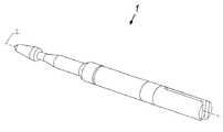
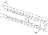
ここで、まず、特に図1から図9の図面を詳細に参照すると、圧力スイッチ1の第1の典型的な実施例を示す。図10から図17は、圧力スイッチ1の第2の典型的な実施例を示す。以下により詳細に示すように、第1の実施例は、「ノーマルオープン」のスイッチ形態を示しており、第2の実施例は、「ノーマルクローズ」のスイッチ形態を示す。2つの実施例でスイッチ1の特徴が同じ部分には、理解し易くするために、同じ符号を使用することとする。 First, with particular reference to the drawings of FIGS. 1 to 9 in particular, a first exemplary embodiment of the
圧力スイッチ1を、器具の長手軸に沿った力を測定するのが必要で、この力が所定の値を越える場合に動作が必要な器具の中に組み込むことができる。この圧力スイッチ1を、例えば、医療機器に使用できるが、医療機器の典型的な実施例に限定されない。以下でさらに詳述するように、圧力スイッチ1を、Mainによる米国特許番号第5,104,025号に開示されているような円形の外科的吻合器具に使用できる。 The
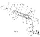
図1から図9は、圧力スイッチ1の様々な部分を表している。図6は、圧力スイッチ1の長手軸2を通した視野の実施例を示しており、スイッチ1の全てのパーツを見ることができる。接触ピストン10が中央部を規定しており、中央部の周りのスイッチ1の他のパーツを説明する。前金具又は先端部20が接触ピストン10の遠位端12に締結されている。遠位端12及び先端部20の内部穴22を図4から図9で直線で示すが、第1の実施例では、遠位端12に外側の雄ねじを設けることができ、穴22に内側の雌ねじを設けることができる。代替的に、先端部20を接触ピストン10の遠位端12に圧入、接着、溶接、又はそうでなければ接続できる。図4から図9に示す形態では、内部穴22の近位端24は、ねじを切っていない平らな部分を有しており、穴22の中に完全にねじ込まれた場合に穴22の中に遠位端12がさらにその中にねじ込まれないためのストッパとして近位部24が機能するように、ピストン10の最も遠位な端部をその中に受容する。 1 to 9 represent various parts of the
ピストン10の近位端には、ピストン10の外側面に幅広部14が設けられており、内部穴16がその内部に形成されている。 At the proximal end of the
中空の本体チューブ30が、接触ピストン10の少なくとも一部の周りに設けられている。チューブ30の内部の実施例は、比較的狭い近位の穴32及び比較的幅が広い遠位の穴34を有している(逆の形態も可能である)。穴32,34は、中央シャフト18及び幅広部14を有するピストン10の近位部を囲んでいる。幅広部14の外側の形状及び近位の穴32の内側の形状は、ほぼ等しい。したがって、円形形態では、近位の穴32の内径が、幅広部14の外径にほぼ等しい。本書で使用するように、2つのパーツ間に十分なクリアランスがある実質的に等しい手段により、一方が他方の中を摺動できる。このため、所定の第1の材料がピストン10の外面とボディチューブ30の内面との間に特定の第1の隙間を要して、ピストン10がその中を移動し得る場合、第1の隙間は、2つのパーツ10,30間に有り、ピストン10の外面とボディチューブ30の内面との間に所定の第2の材料がより小さな(又はより大きな)隙間を要して、ピストン10がその中を移動し得る場合、この第2の隙間は、2つのパーツ10,30間に有る。 A
ピストン10と本体チューブ30との間に2つのパーツ、すなわち調整可能なエンドキャップ40及び付勢装置50が設けられている。エンドキャップ40の外側の形状及び遠位穴34の内側の形状は、実質的に等しい。したがって、円形形態では、遠位穴34の内径が、エンドキャップ40の外径にほぼ等しい。このため、エンドキャップ40を遠位穴34の中に挿入した場合、エンドキャップ40は、遠位及び近位穴34,32の内面、中央シャフト18の外面、幅広部14の遠位の横断面、及びキャップ40の近位の端面、によって規定される内部空間を実質的に閉じる。付勢装置50がこのような内部空間の中に設けられている。付勢装置50及びキャップ40は、幅広部14とともに、所定の方向、このケースでは、近位の方向にピストン10を付勢するよう機能する。付勢装置50の力は、キャップ40の位置に依存させることができる。例えば、キャップ40が幅広部14に近い場合、付勢装置50は第1の付勢力を加えることができ、キャップ40が、幅広部14から遠い場合、付勢装置50が第2の付勢力を加えることができる。使用する付勢装置50に応じて、第1の力を、第2の力よりも大きくすることができ、その逆もまた可能である。キャップ40が本体チューブ30に沿った様々な位置間で調整可能であるのが良いが、必ずしも必要ではない。このような形態では、付勢装置50を調整してユーザが望むように予め付勢することができる。 Two parts are provided between the
キャップ40及び付勢装置50の一実施例を図2から図9に示す。しかしながら、以下の記載は、図8の視野について扱うこととする。本実施例では、遠位穴34が、近位穴32よりも大きな直径を有している。エンドキャップ40が、遠位穴34の図示しない内側の雌ねじに整合する外側のねじ42を有している。このような形態では、キャップ40を遠位穴34の中の長手方向のポイントに沿って遠位穴34の中で回転させることができる。遠位穴34よりも小さな直径を有する近位穴32とともに、近位穴32の遠位の端点36がキャップ40を挿入するためのストッパを形成する。このキャップ40には、ピストン10の中央シャフト18の外側の形状とほぼ等しい形状を有する内側穴44が形成されている。このため、長手方向の力がキャップ40を遠位穴34の外に出さないで押圧するようにキャップ40を遠位穴34の中にねじ込むことができる一方で、ピストン10の中央シャフト18が穴44の中をキャップ40に対して自由に長手方向に移動できる。 One embodiment of the
付勢装置50は、本実施例では、圧縮ばね50として実施されている。圧縮ばね50であるばね50をピストン10の中央シャフト18の周りに幅広部14の遠位の横断面まで設置し、さらに、ねじキャップ40を中央シャフト18の周りに設置して、遠位穴34の中に少なくとも部分的にねじ込むと、キャップ40がしっかりとであるが辛うじて遠位穴34の中にある状態とストッパ36まで中に完全に挿入された状態との間を行き来できる長手方向のコネクション距離によって規定される2つの最大値間でばね50を圧縮できる。 The biasing
ピストン10が移動するため、それは、ピストン10の状態の信号を出すための電気スイッチの1つの接点を形成できる。ピストン10に対して電気的に絶縁された別の接点を設ける必要がある。このため、ピストン10が第1の長手方向の位置にある場合に電気スイッチが第1の状態にあり、ピストン10が第2の長手方向の位置にある場合に第2の状態にあるように(第1及び第2の状態がオフ/オン又はオン/オフする)、ピストン10はスイッチサブアッセンブリと関連する必要がある。このスイッチサブアッセンブリはピストン10の近位端及び本体チューブ30で形成されており、以下の記載では、2つの典型的な実施例で示す。第1の実施例の「ノーマルオープン」スイッチは、図1から図9に関連して言及している。第2の実施例は、図10から17に関連しており、「ノーマルクローズ」スイッチある。 As the
図8から図9を参照してノーマルオープンのスイッチサブアッセンブリについて説明する。スイッチブッシング60が、本体チューブ30の近位端に挿入される遠位に突出するスタブ62を有している。このスタブ62を、多くの方法(例えば、接合、溶接、接着、圧入、ねじ)で本体チューブ30に結合することができる。スイッチブッシング60の近位端が、取り付け本体70に取り付けられる。ある実施例では、ピストン10、先端部20、本体チューブ30、キャップ40、スイッチブッシング60、及び取り付け本体70のそれぞれが導電性を有し、圧力スイッチ1の第1の電気接点を規定する。しかしながら、先端部20及びキャップ40は導電性がある必要はない。電気回路を形成する第2の電気接点を形成(又は図10から図17に示す電気回路を遮断)するために、第2の接点間に絶縁体を配置する必要があり、第1の接点が動作可能に移動して第2の接点と接触する(接触しない)必要がある。 The normally open switch subassembly will be described with reference to FIGS. The
本書に開示されている様々なスイッチの実施例が、導電性のパーツを有しており、電気回路のパーツを実際に形成している。しかしながら、本発明に係るスイッチは、スイッチのパーツが回路を形成する実施例に限定されない。代替的な形態が、本発明の機械式遮断スイッチの態様のみをうまく利用しており、ピストンの移動により、スイッチに隣接する別の電気スイッチ、例えば、ピストンを作動させる。このようなスイッチは非常に小さいため、このような外部スイッチを当技術分野でタクトスイッチと称されるもので実施できる。大きなスイッチのための十分な場所がある場合、様々なマイクロスイッチも同様に使用できる。 The various switch embodiments disclosed herein have conductive parts and actually form the electrical circuit parts. However, the switch according to the present invention is not limited to the embodiment in which the parts of the switch form a circuit. Alternative configurations have successfully utilized only the mechanical shut-off switch aspect of the present invention, and movement of the piston actuates another electrical switch adjacent to the switch, such as a piston. Since such a switch is very small, such an external switch can be implemented with what is referred to in the art as a tact switch. If there is enough room for a large switch, various microswitches can be used as well.
図1から図9の典型的な実施例では、第2の電気接点が環状接触部80によって形成され、絶縁体が絶縁スタブ90によって形成される。リング80及び絶縁スタブ90をピストン10に接続する部分は、T形の接続バー100である。リング80、スタブ90、及びバー100のそれぞれが、簡単に組み立てられてスイッチブッシング及び本体チューブ30に嵌め込まれるように、入れ子になっている。絶縁スタブは、環状接触部80を接続バー100から隔てており、接続バー100は、ピストン10及びスイッチブッシング60と電気的に接触する。 In the exemplary embodiment of FIGS. 1-9, the second electrical contact is formed by an
さらに具体的に、内部穴16が接続バー100の遠位ボス102を受容するような形状となっている。遠位ボス102と内部穴16との間の接続は、ピストン10と先端部10との間の接続の実施例と同じようにすることができる。ボス102が外側の雄ねじを有する場合、例えば、内部穴16が対応する内部の雌ねじを有している。このような典型的な構成は、製造コスト及び時間に関して接続バー100及びピストン10の取り付けを容易にする。 More specifically, the
環状接触部80は、絶縁スタブ90の遠位接触部92の外側の形状と実質的に対応する寸法の形状を有する内部穴82を有している。この遠位接触部92の外側の形状は、例えば、円形、卵形、矩形、方形、星形、三角形といった多角形の形状を取ることができる。このような外側の形状にかかわらず、環状接触部80の内部穴の形状は、環状接触部80に挿入して(圧入、接着、接合、溶接、又は他の接続プロセスによって)それに固定でき、環状接触部80と第1の接点の他の部分との間の接触の規制を高い精度で作成できるように、遠位接触部92の外側の形状に対応する。 The
環状接触部80が絶縁スタブ90に接続された後、組み合わせたアッセンブリを接続ロッド100に接続できる。ロッド100の中間部の外側の形状は、絶縁スタブ90を通して延びる穴94の内部の形状と対応するよう作られる。さらに、ロッド100の中間部の外側の形状は、例えば、円形、卵形、矩形、方形、星形、三角形といった形状を取ることができる。このような外側の形状にかかわらず、絶縁スタブ90の内部穴の形状が、絶縁スタブ90に挿入して(圧入、接着、接合、溶接、又は他の接続プロセスによって)それに固定でき、スタブ90に取り付けられた環状接触部80と第1の接点の他の部分との間の接触の規制を高い精度で作成できるように、ロッド100の中間部の外側の形状に対応する。 After the
このような接続とともに、接続ロッド100が、ピストン10に電気的に接触する(これにより、先端部20、本体チューブ30、キャップ40、スイッチブッシング60、及び取り付け本体70に電気的に接触する)。環状接触部80の外側の形状/外径は、スイッチブッシング60の内側の形状/内径よりも小さい寸法であるが、スイッチブッシング60の内側に環状接触部80を挿入することで、それらの間に横方向の隙間110を形成する。このため、環状接触部80が、横方向の隙間110によってその外側のスイッチブッシング60から電気的に隔離され、絶縁スタブ90の外面に直接接触することによって、その内側の接続ロッド100から電気的に隔離(絶縁)される。 Along with such a connection, the connecting
環状接触部80及び第1の端子(10,20,30,40,60,70)の電気伝導部を有する電気回路を形成するために、環状接触部80で電気的接続を形成しなければならない。このような接続に関するある典型的な実施例を図5から図9に示す。特に、接続バー100に、近位の横方向の外側の面104から、環状接触部80が配置される長手方向の位置に位置する少なくとも接続ロッド100の中間部まで延びる近位の長手方向の穴103を形成する。さらに、横方向の穴106を、長手方向の穴103が環状接触部80の内面と繋がるよう形成してもよい。このような形態では、絶縁ワイヤ206を長手方向103及び横方向104の穴に通して、(例えば、溶接によって)環状接触部80の内面に固定することができる。このような結合を容易にするために、環状接触部80に、ワイヤの電気で動く部分を受容するための凹部(又は一連の凹部)を形成できる一方、ワイヤの絶縁部が接続ロッド100の長手方向103及び横方向104の穴全体に接触した状態を保つ。 In order to form an electrical circuit having an
例えば、このような電気的接続を図7に図式的に示しており、回路200が環状接触部80と取り付け本体70との間に配置されている。このような典型的な回路は、電源202及び電気回路を形成した場合LEDを発光させる接触表示部204(すなわち、LED)を有している。取り付け本体70及び絶縁ワイヤ206を(図7に示すように)それぞれ回路200に接続すると、環状接触部80と第1の端子(10,20,30,40,60,70)と部分との間に電気的接触が生じて、LED204が点灯する。 For example, such an electrical connection is schematically illustrated in FIG. 7, with the
上記のような典型的な形態の説明とともに、第1及び第2の状態の間のスイッチ1の機能を、図8と図9との比較によって説明できる。ピストン10は、先端部20及び接続ロッド100に長手方向に固定されている。さらに、絶縁スタブ90及び環状接触部80が接続ロッド100の外側に長手方向に固定されている。ピストン10は、遠位端がキャップ40の穴44の内側に摺動可能に配置されており、チューブ本体30の近位穴32の内側に摺動可能に配置されている。このため、ピストンサブアッセンブリ全体(10,20,80,90,100)が、長手方向の隙間112が環状接触部80の遠位の横断面とスイッチブッシング60のスタブ64の近位の横断面64間に有るため、長手方向に移動できる。圧力スイッチ1が機能できるのは空間を形成するこのような隙間112による。 Along with the description of the typical form as described above, the function of the
調整キャップ40と幅広部14の遠位の横断面との間に設置された付勢装置(例えば、圧縮バネ)50は、キャップ40を調整してばね50を圧縮する場合にピストン10に対して近位方向の力を与える。この力は、本書ではプレテンションとして称されるが、スイッチブッシング60の導電性のあるスタブ62からある距離−長手方向の隙間112として規定される−を置いて環状接触部80を保持する。圧力スイッチ1に外部の力を与えずに、プレテンションは所定の位置に常に環状接触部80を保持し、第1の接点と環状接触部80との間に電気的接触が生じない。先端部20に与えられる遠位方向の外部の力Fがこの状況を変えることができる。図9を参照されたい。ばねによって加えられる力Fがプレテンション力よりも大きくない場合、ばねは、調整キャップ40によってすでに縮んでいる以上に縮まない。しかしながら、ばねによって加えられる力Fがプレテンション力よりも大きい場合、ばねが縮んで、ピストンサブアッセンブリの残りの部分−ピストン10、接続ロッド100、絶縁スタブ90、及び環状接触部80−とともに先端部20が長手方向に遠位に移動する。長手方向の遠位への移動は、端面64と環状接触部80の遠位側との間の接触が、先端部20のさらなる移動を完全に阻止するため、スイッチブッシング60のスタブ62の近位の端面64によって規制される。このため、このような形態は、スイッチ1が作動して「オープン」となる電気回路が形成される前に環状接触部80がスイッチブッシング60に接触するまで打ち勝つ必要がある調整可能な長手方向のプレテンション力を有する電気スイッチを提供する。図9は、遠位の作動位置にあるピストンサブアッセンブリ(10,20,80,90,100)を示しており、図8は、近位の非作動位置にあるピストンサブアッセンブリを示す。 A biasing device (e.g., a compression spring) 50 installed between the
図1から図9の圧力スイッチ1のアッセンブリのためのある典型的なプロセスは、ピストン10の中央シャフト16を覆うよう挿入されたばね50を有している。また、キャップ40が本体チューブ30の近位穴34の中にねじ込まれる。そして、ピストンばねサブアッセンブリをキャップ40の内部穴44を通して挿入し、先端部20をピストン10の遠位端12に固定する(例えば、ねじで締める)。これにより、ピストンサブアッセンブリを形成する。 One exemplary process for the assembly of the
絶縁スタブ90は、初めに遠位ボス102の周りに、次に、中間部の周りに設置することによって、接続バー100の中間部に取り付けられる。同様に、絶縁スタブ90の外側に設置することによって、環状接触部80が絶縁スタブ90に取り付けられる。環状接触部80は、絶縁スタブ90に長手方向に取り付けられ、スタブ90は、接続バー100の中間部に長手方向に取り付けられる。絶縁ワイヤ206は、取り付け本体70の穴を通され、接続ロッド100の長手方向103及び横方向106の穴を通されて、取り付け本体70又は接続バー100のいかなる部分にもワイヤ206を電気的に接続させずに、環状接触部80の内面に電気的に接続される。このような接続により、すぐにピストンサブアッセンブリに接続し得るスイッチサブアッセンブリを形成する。 The insulating stub 90 is attached to the middle portion of the
接続バー100の遠位のボス102又はスイッチブッシング60のスタブ62の一方又は双方が、ピストン10にボス102を取り付けるための及び/又は本体チューブ30にスタブ62を取り付けるためのねじを有し得る。スイッチサブアッセンブリ全体を(物理的及び電気的に)ピストンサブアッセンブリに接続し得る。これら2つのサブアッセンブリを一緒に組み立てるために、取り付け本体70のみをスイッチブッシング60の近位端に取り付けることを必要とする。このような取り付けは、例えば、溶接又は雄雌セットのねじの形を取り得る。 One or both of the
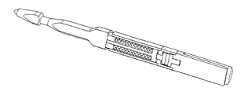
図10から図17は、「ノーマルクローズ」のスイッチ形態を有する圧力スイッチ1の第2の実施形態を示す。 10 to 17 show a second embodiment of the
図10から図17は、スイッチ1の様々な部分を示す。図14は、スイッチ1の全てのパーツを見ることができる圧力スイッチ1をほぼ長手軸2を通して見た例を示す。接触ピストン10が中央部を与えており、中央部の周りのスイッチ1の他の部分を説明する。先端部20を接触ピストン10の遠位端12に固定する。遠位端12及び先端部20の内部穴22を図13から図15及び図17の直線で示すが、典型的な実施例では、遠位端12に外側の雄ねじを設けることができ、穴22に内側の雌ねじを設けることができる。代替的に、先端部20を接触ピストン10の遠位端12に圧入、接着、溶接、又はそうでなければ接続できる。図13から図15及ぶ図17に示す形態では、内部穴22の近位端24は、ねじを切っていない平らな部分を有しており、穴22の中に完全にねじ込まれた場合に穴22の中に遠位端12がさらにその中にねじ込まれないためのストッパとして近位部24が機能するように、ピストン10の最も遠位な端部をその中に受容する。 10 to 17 show various parts of the
ピストン10の近位端には、ピストン10の外側面に半径方向に延びる幅広部14が設けられている。内部穴16がピストン10の近位端の内部に形成されている。 At the proximal end of the
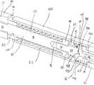
図16の拡大図に示すように、中空の本体チューブ120が、接触ピストン10の少なくとも一部の周りに設けられている。第1の実施例の本体チューブ30と比較すると、チューブ120の内部が一定の径の穴122を有している。穴122は、幅広部14の外側の形状とほぼ等しい形状を有しており、ピストン10の中央シャフト18を囲んでいる。したがって、円形形態では、穴122の内径が幅広部14の外径にほぼ等しい。 As shown in the enlarged view of FIG. 16, a
ピストン10と本体チューブ120との間に配置された圧力スイッチ1の2つのパーツがある:すなわち、ストッパパック130及び付勢装置50である。ばねのストッパパック130の外側の形状及び穴122の内側の形状は、ほぼ等しい。したがって、円形形態では、ばねのストッパパック130が実質的に遊びがないがほぼ摩擦なしに穴122の中を摺動するように、穴122の内径がばねのストッパパック130の外径にほぼ等しい。このばねのストッパパック130は、それが本体チューブ120の中を完全に別々に浮いているという点で、エンドキャップ40とは異なる。特に、先端部20をピストン10の遠位端12にねじ込むと、近位の横断面がパック130の遠位の横断面を押すが、この遠位の横断面に固定されない。このような形態では、一見したところでは、パック130が一定の長手方向の長さを有しているため、それは圧縮ばね50がある所定の圧縮値にのみ設定可能であることを表しているように思われる。これは、各々が異なる長手方向の長さを有している一連のパック130を設けた場合を除いて正しい。このため、パック130のセットのうちの一つを選ぶことによって、ばね50のプレテンションを調整する。また、例えば、図13に示すように、先端部20にピストン10の遠位端12を完全にねじ込む必要がない。このように、先端部20にピストン10が完全にねじ込まれていない場合、付勢装置50のユーザの所望のプレテンションは、特別な大きさのパック130を設け、先端部20に所定の距離だけピストンをねじ込むことによって生じる。代替的に、パック130は、先端部20にピストン10が完全にねじ込まれる場合プレテンションを単に判断できる。ストッパパック130及び付勢装置50のある実施例を図10から図17に示す。しかしながら、以下の実施例では、図13の視野について扱う。ストッパパック130には、ピストン10が妨害されずにパック130を通って行き来できるように、ピストン10の外側の形状とほぼ等しい形状を有する内部穴132が形成されている。 There are two parts of the
ばねストッパパック130が穴122の中にある場合、ストッパパック130は、穴122の内面、中央シャフト18の外面、幅広部14の遠位横断面、及びパック130の近位横断面によって規定される内部空間を実質的に閉止する。付勢装置50はこの内部空間の中に設置されている。付勢装置50及びストッパパック130は、幅広部14とともに動作して、所定の方向、このケースでは近位の方向にピストン10を付勢する。付勢装置50の力は、ストッパパック130の長手方向の長さに依存する。 When the
本実施例では、付勢装置50が圧縮ばね50として実施される。圧縮ばね50であるばね50がピストン10の中央シャフト18の周りに幅広部14の遠位の横断面まで設置される場合、ストッパパック130もまた中央シャフト18の周りにあり先端部20がピストン10に取り付けられる場合、ばね50がそれらの間で縮むか又はプリテンションする。 In this embodiment, the urging
ピストン10が移動するため、それは、圧力スイッチ1の状態の信号を出すための電気スイッチの1つの接点を形成できる。ピストン10に対して電気的に絶縁された別の接点を必要とする。このため、ピストン10が第1の長手方向の位置にある場合に電気式圧力スイッチ1が第1の状態にあり、ピストン10が第2の長手方向の位置にある場合に第2の状態にあるように(第1及び第2の状態がオフ/オン又はオン/オフする)、ピストン10はスイッチサブアッセンブリと関連する必要がある。このスイッチサブアッセンブリは、ピストン10の近位端及び本体チューブ120で形成されており、以下の記載では、第2の典型的な「ノーマルクローズの」実施例に適用される。 As the
スイッチブッシング60は、遠位に突出するスタブ62を有しており、スタブ62が本体チューブ120の近位端に挿入される。スタブ62をあらゆる方法(例えば、接合、溶接、接着、圧入、ねじ)を用いて本体チューブ120に取り付けることができる。スイッチブッシング60の近位端が、取り付け本体70に取り付けられる。ある実施例では、ピストン10、先端部20、本体チューブ120、ストッパパック130、スイッチブッシング60、及び取り付け本体70のそれぞれが導電性を有し、圧力スイッチ1の第1の電気接点を規定する。しかしながら、先端部20及びストッパパック130は必ずしも導電性である必要がない。第1の接点に電気的に接続された場合に、図10から図17に示す電気回路を遮断する第2の電気接点を形成するために、第2の接点と第1の接点との間に絶縁体を配置する必要があり、第1の接点が動作可能に移動して第2の接点と接触する必要がある。 The
図10から図17の典型的な実施例では、第2の電気接点が接続ピン140によって形成され、絶縁体が絶縁ブッシング150によって形成される。絶縁ブッシング150及び接続ピン140をピストン10に接続する部分は、T形の導電性の接続ねじ160である。絶縁ブッシング150及び接続ピン140は、簡単に組み立てられてスイッチブッシング60及び取り付け本体70に嵌め込まれるように、入れ子になっている。絶縁ブッシング150は、少なくともピストン10及びスイッチブッシング60と電気的に接触する接続ピン140を、取り付け本体70及びスイッチブッシング60から物理的及び電気的に隔てられている。 In the exemplary embodiment of FIGS. 10-17, the second electrical contact is formed by the connecting
さらに具体的に、内部穴16が接続ねじ160の遠位ボス162を受容するような形状となっている。遠位ボス162と内部穴16との間の接続は、ピストン10と先端部10との間の接続の実施例と同じようにすることができる。ボス162が外側の雄ねじを有する場合、例えば、内部穴16が対応する内部の雌ねじを有している。このような典型的な構成は、製造コスト及び時間に関して接続ねじ160及びピストン10の取り付けを容易にする。また、接続ねじ160の横方向の端面164は、ピストン10の内部穴16の内側の遠位ボス162が完全に挿入されたことを表示するストッパを与える。 More specifically, the
絶縁ブッシング150は、接続ピン140の近位接触部142の外側の形状と実質的に対応する寸法の形状を有する内部穴152を有している。この近位接触部142の外側の形状は、例えば、円形、卵形、矩形、方形、星形、三角形といった多角形の形状を取ることができる。このような外側の形状にかかわらず、絶縁ブッシング150の内部穴152の形状は、絶縁ブッシング150を挿入して(圧入、接着、接合、溶接、又は他の接続プロセスによって)内部穴152に固定でき、接続ピン140と第1の接点の他の部分との間の接触の規制を高い精度で作成できるように、近位接触部142の外側の形状に対応する。 The insulating
絶縁ブッシング150が接続ピン140に接続された後、組み合わせた絶縁サブアッセンブリを取り付け本体70に接続できる。絶縁ブッシング150の近位部の外側の形状は、取り付け本体70を通して延びる内側穴72の内側の形状と一致するよう作られる。さらに、絶縁ブッシング150の近位部の外側の形状は、例えば、円形、卵形、矩形、方形、星形、三角形といった形状を取ることができる。このような外側の形状にかかわらず、取り付け本体70の内部穴の形状が、絶縁ブッシング150を内部穴に挿入して内部穴に固定でき、(絶縁ブッシング150及び取り付け本体70に取り付けられた)接続ピン140と第1の接点の他の部分との間の接触の規制を高い精度で作成できるように、絶縁ブッシング150に対応する。 After the insulating
このような接続とともに、接続ねじ160が、ピストン10に電気的に接触する(これにより、本体チューブ120、スイッチブッシング60、及び取り付け本体70、さらに場合によっては、必要に応じて、先端部20及びストッパパック130に電気的に接触する)。接続ピン140の遠位の横方向の幅広部144の外側の形状/直径は、スイッチブッシング60の内側の形状/直径よりも小さい寸法であり、スイッチブッシング60の内側に接続ピン140を挿入することで、それらの間に横方向の隙間110を形成する。このため、横方向の隙間110が、スイッチブッシング60の内側から接続ピン140の遠位の幅広部144を電気的に隔離し、接続ピン140の近位の接触部142の外側が、絶縁ブッシング150の内側穴152に直接接触することによって、取り付け本体70及びスイッチブッシング60から電気的に隔離(絶縁)される。 With such a connection, the
接続ピン140と第1の端子(10,20,60,70,120,130)の電気伝導部との間に電気回路を形成するために、接続ピン140で電気的接続を形成しなければならない。このような接続に関するある典型的な実施例を図11から図17に示す。特に、接続ねじ160に、中間部から半径方向に延びて近位の横断面168を規定する近位の横方向の幅広部166を形成する。付勢装置50がピストン10及び接続ねじ160を近位の方向に付勢して、接続ピン140の遠位の横断面148を接続ねじ160の近位の横断面168に導通するよう接触させる。このような接触は、これら2つの面間でサブアッセンブリの電気回路を形成させるだけでよいため、接続ねじ160の近位の幅広部166の外側の形状/外径は、スイッチベアリング60の内部穴66の中を摺動するような大きさ又は形状とすることができる。 In order to form an electrical circuit between the
接続ピン140の他の電気接点が、接続ピン140の近位の側に具わっている。ある典型的な実施例では、長手方向の穴146が、接続ピン140の近位の横断面から内側に形成されており、絶縁ワイヤ206をその中に受容する。このワイヤ206の導電体を長手方向の穴146の内面に(例えば、溶接によって)固定し得る。このような電気的な接続を、例えば、図7に図式的に示す。このような典型的な形態では、電源202が接触表示器204(LED)に電力を供給し、電気回路が導通するときにLEDを点灯させるが、圧力スイッチ1のこのようなノーマルクローズの形態では、常にそのようになる。逆に、第1の接点と接続ピン140との間の電気的接触を解除すると、LED104が消灯する。当然ながら、表示器は目視によるもの(例えば、LED104)である必要がない。また、それは、音声によるもの(例えば、スピーカの音)又は触覚(例えば、振動)、又はこれらの組み合わせとすることができる。 Another electrical contact of the connecting
また、接続ピン140と取り付け本体70との間に、電気回路がオープン(すなわち、導通していない)のときにLEDを点灯させる回路300を設けることが可能である。任意のロジック回路を使用して、図10から図17に示すような圧力スイッチ1の2つの状態に基づいてLED204を制御できる。例えば、図13に示すように、NORゲート及びANDゲートを有するロジック300を、圧力スイッチ1回路に接続できる。このような形態では、スイッチ1がそのノーマルクローズ状態のときにLEDがオフになり、図17に示すように接触が断たれると、LEDが点灯する。 Further, it is possible to provide a
上記の典型的な形態の説明とともに、第1及び第2の状態間のスイッチ1の機能を、図16と図17との間の比較によって説明できる。 Along with the description of the above typical form, the function of the
上記のように、接続ピン140は、絶縁ブッシング150の中に長手方向に固定されており、絶縁ブッシング150がスイッチベアリング60及び取り付け本体70の少なくとも一方に長手方向に固定されている。本体チューブ120が、スイッチベアリング60の遠位端に長手方向に固定されている。ストッパパック130が、ばね50と先端部20との間に長手方向に拘束されずに設けられている。ピストン10が先端部20及び接続ねじ160に長手方向に固定されており、ピストンサブアッセンブリがばね50によって近位方向に付勢されながら本体120の中を摺動する。したがって、ピストンサブアッセンブリ(10,20,130,160)全体が遠位の長手方向に移動して、本体チューブ120の内側のばね50を圧縮し、この圧縮の距離が、圧力スイッチ1がスイッチとして機能する空間134(図17参照)を形成する。 As described above, the connecting
パック130と幅広部14の遠位の横断面との間に設置された付勢装置(例えば、圧縮ばね)50は、パック130がばね50を圧縮する場合にピストン10に対して近位方向の力を与える。この力は、本書ではプレテンションとして称されるが、接続ピン140の導電性の遠位の横断面に対して接続ねじ160を保持する。圧力スイッチ1に外部の力を与えずに、プレテンションはこの位置に常に接続ピン140を保持し、第1の接点と接続ピン140との間の電気的接触が維持される。先端部20に与えられる遠位方向の外部の力Fがこの状況を変えることができる。図17を参照されたい。力Fがばね50によって加えられるプレテンション力よりも大きくない場合、ばね50は、パック130によってすでに縮んでいる以上に縮まない。しかしながら、力Fがばね50によってピストン10に加えられるプレテンション力よりも大きい場合、ばね50がさらに縮んで、ピストンサブアッセンブリ(10,130,160)の残りの部分とともに先端部20が遠位の長手方向に移動する。遠位の長手方向はばね50の大きな圧縮移動によって規制され、圧力スイッチ1の大部分の適用では、それは生じない。このため、このような形態は、スイッチ1が作動できて「クローズ」の電気回路が形成される前に接続ねじ160が接続ピン140に接触しなくなるまで打ち勝つ必要がある調整可能な長手方向のプレテンション力を有する電気スイッチを提供する。図17及び図19は、遠位の作動位置にあるピストンサブアッセンブリ(10,130,160)を示しており、図16は、近位の非作動位置にあるピストンサブアッセンブリを示す。 A biasing device (eg, a compression spring) 50 installed between the
図10から図17の圧力スイッチ1のアッセンブリのためのある典型的なプロセスでは、突出するスタブ62を有するスイッチブッシング60の遠位端が、本体チューブ120の近位端に長手方向に固定されている。ピストン10を本体チューブ120の内側に挿入し、ばね50を本体チューブ120の内側にピストン10の中央シャフト16を覆うよう挿入する。パック130をピストン10の遠位端12の外側に設置し、先端部20にピストン10の遠位端12の外側のねじを完全に又は部分的にねじ込む。ここで、先端部にピストン10完全にねじ込むと、ピストン10がスイッチブッシングのスタブ62にプレテンション力を与える。このような力を避けるために、先端部20にピストン10の遠位端12を部分的にねじ込むことができる。そして、接続ねじ160の遠位端をピストン10の内部穴16の中にねじ込んで、ピストン10の幅広部14と接続ねじ160の幅広部166との間にスタブ62を捕らえる。これによりピストンばねサブアッセンブリを形成する。 In one exemplary process for assembly of the
取り付け本体70が接続ピン140に長手方向に固定されて接続されており、それらの間に絶縁ブッシング150を具えている。これらのパーツの入れ子式の形状のため、取り付けの順序が取り付けするためのコスト及び時間のみによって限定される。代替的に、絶縁ブッシング150及び接続ピン140を取り付け本体70の遠位端の内側に設置できるが、このようなケースでは、圧力スイッチ1の遠位端を下方に傾ける場合これら2つのパーツが長手方向に移動できる。これにより接続ピンサブアッセンブリを形成する。 A mounting
ピストンばね及び接続ピンサブアッセンブリは、スイッチブッシング60に取り付け本体70を長手方向に固定することによって一緒に取り付けられる。先端部20にピストン10を完全にねじ込むと、固定によるばね50の予めの付勢力に打ち勝つ必要がある。しかしながら、ばね50に予めの付勢力が生じないように先端部20にピストン10を最小限ねじ込むと、長手方向の全ての固定がなされた後に、先端部20にピストン10の遠位端12を完全にねじ込んでばね50をプレテンションの状態にし得る。絶縁ワイヤ206の導電体が接続ピン140の長手方向の穴146に取り付けられ、回路300を形成する。 The piston spring and the connecting pin subassembly are attached together by securing the mounting
ノーマルオープン及びノーマルクローズの形態の各ケースでは、長手方向の隙間112が、約25μm(0.001”)から約750μm(0.030”)の間、又はより狭い範囲では約75μm(0.003”)から約200μm(0.008”)の間の長さを有している。 In each case of the normally open and normally closed configurations, the
圧力スイッチ1の導電性のある部分は、例えば、ステンレス鋼、銅、ニッケルメッキした銅、ニッケルメッキした真鍮とし得る。絶縁ワイヤ206の導電体を半田付けする必要が場合、これらの各材質で差し支えないであろう。 The conductive part of the
2つの状態の間を切り替えるために適用可能な圧力スイッチ1の力の範囲は、約3オンスから約20ポンドの間、又はより狭い範囲である約5ポンドから約8ポンドの間とすることが可能である。 The range of
ばね50を選択する方法に関しては、所定の一連のばね50の中間の範囲内又はその範囲で所望のプレテンション力を選択する。換言すれば、圧力スイッチの状態の変化が、ばね50のプレテンションのスペクトルの最大値の近くで生じるのではなくて、その代わりに、スペクトルの中央部のどこかで生じる。 With respect to the method of selecting the
上記の回路は、二進出力−圧力スイッチ1を通して伝達される外部の物体への力がプレテンションよりも大きいか又は小さいか−を与える。圧力スイッチにロードセルとも称される歪みゲージを設ける場合、連続的な力の出力の表示、例えば、1列のLEDが力の量に応じて段階的に点灯する、又はLED又はLCDの数値欄が圧力スイッチ1を通して与えられる力の量に対応する数値を増加させる、といった表示をユーザにすることができる。 The above circuit provides a binary output-whether the force on the external object transmitted through the
ここで、上記の圧力スイッチ1を、Main(「Main」)らによるEthiconEndo−Surgery,Incに譲渡された米国特許第5,104,025号に記載された腔内吻合環状ステープラーでの使用に関して説明することとする。Mainの特許の図7の分解図に最も明りょうに示されているように、トロカール(套管針)シャフト22が、アンビルの鋸歯29にトロカールシャフト22を並べるための遠位の窪み部21及びいくつかの凹部28を有しているため、アンビル34にステープを合わせる。トロカール先端部26は、それに圧力を加えると組織を貫通し得る。Mainの特許の図3から図6は、環状ステープラー10がどのように2つの組織片を一緒に結合するのかを示す。アンビル30をヘッド20の近くに移動させると、図5及び図6に示すように組織がその間で圧縮される。この組織を圧縮し過ぎると、このような外科的な吻合手術は成功しないであろう。外科手術の間、挟まった組織に許容範囲にある圧縮力を加えることができる。この範囲は既知であり、吻合する組織に依存する。Mainの特許で図示するステープラーは、吻合に先立って組織に加えられる圧縮力のレベルをユーザに示すことができない。しかしながら、本書に記載された圧力スイッチ1はトロカールシャフト22の代わりであり、ステープラー10が、(圧力スイッチ1の長手軸2に沿って作用する)圧縮力がスイッチ1のプレテンションをいつ越えたのかを、ユーザに示すことができる。容認できる組織圧縮力の範囲内に値を有するように、このプレテンションをユーザが選択できる。 The
本出願の図1から図10は、Ethicon Endo−Surgery,Inc.によって製造販売される少なくともCDH外科的ステープラーの中で機能し得る先の鋭い遠位端を有する先端部20を示す。Mainの特許のトロカールシャフト22の近位端は、ヘッド20に取り付けるために雄ねじを要する。他の環状ステープラーは、本出願の図1から図10に示すのとは反対のタング(tang)の実施例を要する。このため、取り付け本体70を図1から図17に示す形式又はMainの特許の図7に示す形式にすることができる。先端部20及び取り付け本体70を、あらゆる種類の同じような外科装置に嵌り込むようカスタマイズできる。 1 to 10 of the present application are shown in Ethicon Endo-Surgery, Inc. FIG. 2 shows a
前述の記載及び添付図面は、本発明の原理、好適な実施例及び動作方法を示している。しかしながら、本発明が上記の特定の実施例に限定されると解釈されるべきではない。上記の実施例の追加的なバリエーションが、当業者にとって明らかであろう。 The foregoing description and accompanying drawings illustrate the principles, preferred embodiments and methods of operation of the present invention. However, this invention should not be construed as limited to the particular embodiments described above. Additional variations of the above example will be apparent to those skilled in the art.
このため、上記の実施例は、限定的なものではなくむしろ実例と見なすべきである。したがって、当然のことながら、上記の特許請求の範囲によって規定される本発明の範囲から逸脱することなしに、これらの実施例に対する変更を当業者が成し得る。 Thus, the above embodiments should be regarded as illustrative rather than limiting. Thus, it will be appreciated that modifications to these embodiments can be made by those skilled in the art without departing from the scope of the invention as defined by the appended claims.
Claims (19)
Translated fromJapanese前記器具の前記長手方向の装置軸に対して平行に設けられた長手方向の切り替え軸を有する切り替え部材と;
前記切り替え軸に沿って前記切り替え部材が移動可能に設置される内部空洞を規定する中空本体であって、前記切り替え軸に沿った第1の長手方向の位置のスイッチ導通位置と、前記第1の長手方向の位置とは異なる前記切り替え軸に沿った第2の長手方向の位置のスイッチ遮断位置とを規定する中空本体と;
前記切り替え部材に対して可変の長手方向の付勢力を与える付勢部材であって、前記切り替え軸に沿って前記切り替え部材に与えられる外部の力が、前記長手方向の付勢力を越えるまで、前記スイッチ導通位置及び前記スイッチ遮断位置の一方に前記切り替え部材を配置し、これにより、前記切り替え部材が前記スイッチ導通位置及び前記スイッチ遮断位置の他方に移動する、付勢部材と;
前記切り替え部材に結合される導電性の接点であって、前記切り替え部材が前記スイッチ導通位置にある場合のスイッチ導通状態と、前記切り替え部材が前記スイッチ遮断位置にある場合のスイッチ遮断状態と、を規定する導電性の接点と;
を具えることを特徴とするスイッチ器具。A switch device having a longitudinal device axis, the switch comprising:
A switching member having a longitudinal switching axis provided parallel to the longitudinal device axis of the instrument;
A hollow body defining an internal cavity in which the switching member is movably installed along the switching axis, the switch conducting position at a first longitudinal position along the switching axis; and the first A hollow body defining a switch cutoff position at a second longitudinal position along the switching axis that is different from the longitudinal position;
An urging member for applying a variable longitudinal urging force to the switching member until an external force applied to the switching member along the switching shaft exceeds the longitudinal urging force; An urging member that disposes the switching member at one of a switch conducting position and the switch shut-off position, whereby the switching member moves to the other of the switch conducting position and the switch shut-off position;
A conductive contact coupled to the switching member, the switch conducting state when the switching member is in the switch conducting position, and the switch breaking state when the switching member is in the switch shutting position. A conductive contact as defined;
A switch device characterized by comprising:
前記導電性の接点と;
前記長手方向に固定され、前記中空本体に電気的に導通するよう結合されて前記導電性の接点を少なくとも部分的に囲むスイッチハウジングと;
前記導電性の接点と前記スイッチハウジングとを電気的に絶縁するスイッチ碍子と;
前記スイッチハウジングに移動可能に配置され、前記長手方向に固定されて前記ピストンに電気的に導通するよう結合されたピストン接点と;
を有することを特徴とする請求項2に記載のスイッチ器具。In addition, a switch subassembly is provided, the switch subassembly being
Said conductive contact;
A switch housing fixed in the longitudinal direction and coupled in electrical communication with the hollow body to at least partially surround the conductive contact;
A switch insulator that electrically insulates the conductive contact from the switch housing;
It said movably disposed in the switch housing, a piston contacts coupled to be fixed tothe longitudinal electrically conductive to said piston;
The switch device according to claim 2, comprising:
前記付勢接点が、前記第1の外面よりも直径が大きい第2の外面を有し、
前記中空本体の内部空洞が、前記第2の外面と直径がほぼ等しい第1の内面を有し、
前記第2の内部空洞が、前記第1の外面と直径がほぼ等しい第2の内面を有し、
前記付勢接点が、前記第1の内面と直径がほぼ等しい第3の外面を有し、
前記導電性の接点が、前記第1の内面よりも直径が小さい第4の外面を有することを特徴とする請求項5に記載のスイッチ器具。The switching member has a first outer surface;
The biasing contact has a second outer surface having a larger diameter than the first outer surface;
An internal cavity of the hollow body has a first inner surface substantially equal in diameter to the second outer surface;
The second internal cavity has a second inner surface substantially equal in diameter to the first outer surface;
The biasing contact has a third outer surface having a diameter substantially equal to the first inner surface;
6. The switch device according to claim 5, wherein the conductive contact has a fourth outer surface having a diameter smaller than that of the first inner surface.
前記切り替え部材及び前記導電性の接点に電気的に接続され、
状態変化情報を送信して前記切り替え部材の状態変化が発生したことを使用者に示すよう動作可能な表示部を有することを特徴とする請求項1に記載のスイッチ器具。Furthermore, an electric display circuit is provided, and the electric display circuit is
Electrically connected to the switching member and the conductive contact;
The switch device according to claim 1, further comprising a display unit operable to transmit the state change information to indicate to the user that the state change of the switching member has occurred.
Applications Claiming Priority (10)
| Application Number | Priority Date | Filing Date | Title |
|---|---|---|---|
| US80198906P | 2006-05-19 | 2006-05-19 | |
| US60/801,989 | 2006-05-19 | ||
| US81027206P | 2006-06-02 | 2006-06-02 | |
| US60/810,272 | 2006-06-02 | ||
| US85811206P | 2006-11-09 | 2006-11-09 | |
| US60/858,112 | 2006-11-09 | ||
| US90253407P | 2007-02-21 | 2007-02-21 | |
| US60/902,534 | 2007-02-21 | ||
| US11/750,622 | 2007-05-18 | ||
| US11/750,622US7479608B2 (en) | 2006-05-19 | 2007-05-18 | Force switch |
Related Parent Applications (1)
| Application Number | Title | Priority Date | Filing Date |
|---|---|---|---|
| JP2010204594ADivisionJP5134056B2 (en) | 2006-05-19 | 2010-09-13 | pressure switch |
Related Child Applications (1)
| Application Number | Title | Priority Date | Filing Date |
|---|---|---|---|
| JP2013229885ADivisionJP5840666B2 (en) | 2006-05-19 | 2013-11-06 | pressure switch |
Publications (2)
| Publication Number | Publication Date |
|---|---|
| JP2013080706A JP2013080706A (en) | 2013-05-02 |
| JP5410593B2true JP5410593B2 (en) | 2014-02-05 |
Family
ID=38711012
Family Applications (7)
| Application Number | Title | Priority Date | Filing Date |
|---|---|---|---|
| JP2009511258AActiveJP4625538B2 (en) | 2006-05-19 | 2007-05-21 | pressure switch |
| JP2010204594AActiveJP5134056B2 (en) | 2006-05-19 | 2010-09-13 | pressure switch |
| JP2010204593AActiveJP5248565B2 (en) | 2006-05-19 | 2010-09-13 | pressure switch |
| JP2012246009AActiveJP5410593B2 (en) | 2006-05-19 | 2012-11-08 | pressure switch |
| JP2013229885AActiveJP5840666B2 (en) | 2006-05-19 | 2013-11-06 | pressure switch |
| JP2015220874AActiveJP6396877B2 (en) | 2006-05-19 | 2015-11-11 | pressure switch |
| JP2018161098AActiveJP6937728B2 (en) | 2006-05-19 | 2018-08-30 | pressure switch |
Family Applications Before (3)
| Application Number | Title | Priority Date | Filing Date |
|---|---|---|---|
| JP2009511258AActiveJP4625538B2 (en) | 2006-05-19 | 2007-05-21 | pressure switch |
| JP2010204594AActiveJP5134056B2 (en) | 2006-05-19 | 2010-09-13 | pressure switch |
| JP2010204593AActiveJP5248565B2 (en) | 2006-05-19 | 2010-09-13 | pressure switch |
Family Applications After (3)
| Application Number | Title | Priority Date | Filing Date |
|---|---|---|---|
| JP2013229885AActiveJP5840666B2 (en) | 2006-05-19 | 2013-11-06 | pressure switch |
| JP2015220874AActiveJP6396877B2 (en) | 2006-05-19 | 2015-11-11 | pressure switch |
| JP2018161098AActiveJP6937728B2 (en) | 2006-05-19 | 2018-08-30 | pressure switch |
Country Status (7)
| Country | Link |
|---|---|
| US (11) | US7479608B2 (en) |
| EP (4) | EP2033203B1 (en) |
| JP (7) | JP4625538B2 (en) |
| CN (1) | CN102737868B (en) |
| AU (3) | AU2007253768B2 (en) |
| CA (2) | CA2908109C (en) |
| WO (1) | WO2007137215A2 (en) |
Families Citing this family (543)
| Publication number | Priority date | Publication date | Assignee | Title |
|---|---|---|---|---|
| US9060770B2 (en) | 2003-05-20 | 2015-06-23 | Ethicon Endo-Surgery, Inc. | Robotically-driven surgical instrument with E-beam driver |
| US20070084897A1 (en) | 2003-05-20 | 2007-04-19 | Shelton Frederick E Iv | Articulating surgical stapling instrument incorporating a two-piece e-beam firing mechanism |
| US9072535B2 (en) | 2011-05-27 | 2015-07-07 | Ethicon Endo-Surgery, Inc. | Surgical stapling instruments with rotatable staple deployment arrangements |
| US11998198B2 (en) | 2004-07-28 | 2024-06-04 | Cilag Gmbh International | Surgical stapling instrument incorporating a two-piece E-beam firing mechanism |
| US8215531B2 (en) | 2004-07-28 | 2012-07-10 | Ethicon Endo-Surgery, Inc. | Surgical stapling instrument having a medical substance dispenser |
| US11890012B2 (en) | 2004-07-28 | 2024-02-06 | Cilag Gmbh International | Staple cartridge comprising cartridge body and attached support |
| US8627995B2 (en)* | 2006-05-19 | 2014-01-14 | Ethicon Endo-Sugery, Inc. | Electrically self-powered surgical instrument with cryptographic identification of interchangeable part |
| US7959050B2 (en)* | 2005-07-26 | 2011-06-14 | Ethicon Endo-Surgery, Inc | Electrically self-powered surgical instrument with manual release |
| US8573462B2 (en) | 2006-05-19 | 2013-11-05 | Ethicon Endo-Surgery, Inc. | Electrical surgical instrument with optimized power supply and drive |
| US9554803B2 (en) | 2005-07-26 | 2017-01-31 | Ethicon Endo-Surgery, Llc | Electrically self-powered surgical instrument with manual release |
| US8627993B2 (en)* | 2007-02-12 | 2014-01-14 | Ethicon Endo-Surgery, Inc. | Active braking electrical surgical instrument and method for braking such an instrument |
| US10314583B2 (en) | 2005-07-26 | 2019-06-11 | Ethicon Llc | Electrically self-powered surgical instrument with manual release |
| US8579176B2 (en) | 2005-07-26 | 2013-11-12 | Ethicon Endo-Surgery, Inc. | Surgical stapling and cutting device and method for using the device |
| US9662116B2 (en) | 2006-05-19 | 2017-05-30 | Ethicon, Llc | Electrically self-powered surgical instrument with cryptographic identification of interchangeable part |
| US7479608B2 (en) | 2006-05-19 | 2009-01-20 | Ethicon Endo-Surgery, Inc. | Force switch |
| US11751873B2 (en) | 2005-07-26 | 2023-09-12 | Cilag Gmbh International | Electrically powered surgical instrument with manual release |
| US11484312B2 (en) | 2005-08-31 | 2022-11-01 | Cilag Gmbh International | Staple cartridge comprising a staple driver arrangement |
| US9237891B2 (en) | 2005-08-31 | 2016-01-19 | Ethicon Endo-Surgery, Inc. | Robotically-controlled surgical stapling devices that produce formed staples having different lengths |
| US7669746B2 (en) | 2005-08-31 | 2010-03-02 | Ethicon Endo-Surgery, Inc. | Staple cartridges for forming staples having differing formed staple heights |
| US7673781B2 (en) | 2005-08-31 | 2010-03-09 | Ethicon Endo-Surgery, Inc. | Surgical stapling device with staple driver that supports multiple wire diameter staples |
| US11246590B2 (en) | 2005-08-31 | 2022-02-15 | Cilag Gmbh International | Staple cartridge including staple drivers having different unfired heights |
| US7934630B2 (en) | 2005-08-31 | 2011-05-03 | Ethicon Endo-Surgery, Inc. | Staple cartridges for forming staples having differing formed staple heights |
| US10159482B2 (en) | 2005-08-31 | 2018-12-25 | Ethicon Llc | Fastener cartridge assembly comprising a fixed anvil and different staple heights |
| US8800838B2 (en) | 2005-08-31 | 2014-08-12 | Ethicon Endo-Surgery, Inc. | Robotically-controlled cable-based surgical end effectors |
| US20070106317A1 (en) | 2005-11-09 | 2007-05-10 | Shelton Frederick E Iv | Hydraulically and electrically actuated articulation joints for surgical instruments |
| US8161977B2 (en) | 2006-01-31 | 2012-04-24 | Ethicon Endo-Surgery, Inc. | Accessing data stored in a memory of a surgical instrument |
| US7845537B2 (en) | 2006-01-31 | 2010-12-07 | Ethicon Endo-Surgery, Inc. | Surgical instrument having recording capabilities |
| US8763879B2 (en) | 2006-01-31 | 2014-07-01 | Ethicon Endo-Surgery, Inc. | Accessing data stored in a memory of surgical instrument |
| US9861359B2 (en) | 2006-01-31 | 2018-01-09 | Ethicon Llc | Powered surgical instruments with firing system lockout arrangements |
| US20120292367A1 (en) | 2006-01-31 | 2012-11-22 | Ethicon Endo-Surgery, Inc. | Robotically-controlled end effector |
| US20110295295A1 (en) | 2006-01-31 | 2011-12-01 | Ethicon Endo-Surgery, Inc. | Robotically-controlled surgical instrument having recording capabilities |
| US11224427B2 (en) | 2006-01-31 | 2022-01-18 | Cilag Gmbh International | Surgical stapling system including a console and retraction assembly |
| US20110024477A1 (en) | 2009-02-06 | 2011-02-03 | Hall Steven G | Driven Surgical Stapler Improvements |
| US11793518B2 (en) | 2006-01-31 | 2023-10-24 | Cilag Gmbh International | Powered surgical instruments with firing system lockout arrangements |
| US8820603B2 (en) | 2006-01-31 | 2014-09-02 | Ethicon Endo-Surgery, Inc. | Accessing data stored in a memory of a surgical instrument |
| US8708213B2 (en) | 2006-01-31 | 2014-04-29 | Ethicon Endo-Surgery, Inc. | Surgical instrument having a feedback system |
| US7753904B2 (en) | 2006-01-31 | 2010-07-13 | Ethicon Endo-Surgery, Inc. | Endoscopic surgical instrument with a handle that can articulate with respect to the shaft |
| US8186555B2 (en) | 2006-01-31 | 2012-05-29 | Ethicon Endo-Surgery, Inc. | Motor-driven surgical cutting and fastening instrument with mechanical closure system |
| US11278279B2 (en) | 2006-01-31 | 2022-03-22 | Cilag Gmbh International | Surgical instrument assembly |
| US8992422B2 (en) | 2006-03-23 | 2015-03-31 | Ethicon Endo-Surgery, Inc. | Robotically-controlled endoscopic accessory channel |
| US8236010B2 (en) | 2006-03-23 | 2012-08-07 | Ethicon Endo-Surgery, Inc. | Surgical fastener and cutter with mimicking end effector |
| US8777979B2 (en) | 2006-04-17 | 2014-07-15 | Covidien Lp | System and method for mechanically positioning intravascular implants |
| JP5230602B2 (en) | 2006-04-17 | 2013-07-10 | タイコ ヘルスケア グループ リミテッド パートナーシップ | System and method for mechanically positioning an endovascular implant |
| US8322455B2 (en) | 2006-06-27 | 2012-12-04 | Ethicon Endo-Surgery, Inc. | Manually driven surgical cutting and fastening instrument |
| US7506791B2 (en) | 2006-09-29 | 2009-03-24 | Ethicon Endo-Surgery, Inc. | Surgical stapling instrument with mechanical mechanism for limiting maximum tissue compression |
| US10130359B2 (en) | 2006-09-29 | 2018-11-20 | Ethicon Llc | Method for forming a staple |
| US10568652B2 (en) | 2006-09-29 | 2020-02-25 | Ethicon Llc | Surgical staples having attached drivers of different heights and stapling instruments for deploying the same |
| US11980366B2 (en) | 2006-10-03 | 2024-05-14 | Cilag Gmbh International | Surgical instrument |
| US8459520B2 (en) | 2007-01-10 | 2013-06-11 | Ethicon Endo-Surgery, Inc. | Surgical instrument with wireless communication between control unit and remote sensor |
| US8632535B2 (en)* | 2007-01-10 | 2014-01-21 | Ethicon Endo-Surgery, Inc. | Interlock and surgical instrument including same |
| US11291441B2 (en) | 2007-01-10 | 2022-04-05 | Cilag Gmbh International | Surgical instrument with wireless communication between control unit and remote sensor |
| US8652120B2 (en)* | 2007-01-10 | 2014-02-18 | Ethicon Endo-Surgery, Inc. | Surgical instrument with wireless communication between control unit and sensor transponders |
| US8684253B2 (en) | 2007-01-10 | 2014-04-01 | Ethicon Endo-Surgery, Inc. | Surgical instrument with wireless communication between a control unit of a robotic system and remote sensor |
| US11039836B2 (en) | 2007-01-11 | 2021-06-22 | Cilag Gmbh International | Staple cartridge for use with a surgical stapling instrument |
| US20080169333A1 (en) | 2007-01-11 | 2008-07-17 | Shelton Frederick E | Surgical stapler end effector with tapered distal end |
| US7673782B2 (en) | 2007-03-15 | 2010-03-09 | Ethicon Endo-Surgery, Inc. | Surgical stapling instrument having a releasable buttress material |
| US8893946B2 (en) | 2007-03-28 | 2014-11-25 | Ethicon Endo-Surgery, Inc. | Laparoscopic tissue thickness and clamp load measuring devices |
| US7832408B2 (en)* | 2007-06-04 | 2010-11-16 | Ethicon Endo-Surgery, Inc. | Surgical instrument having a directional switching mechanism |
| US11564682B2 (en) | 2007-06-04 | 2023-01-31 | Cilag Gmbh International | Surgical stapler device |
| US8931682B2 (en) | 2007-06-04 | 2015-01-13 | Ethicon Endo-Surgery, Inc. | Robotically-controlled shaft based rotary drive systems for surgical instruments |
| US8534528B2 (en) | 2007-06-04 | 2013-09-17 | Ethicon Endo-Surgery, Inc. | Surgical instrument having a multiple rate directional switching mechanism |
| US7753245B2 (en) | 2007-06-22 | 2010-07-13 | Ethicon Endo-Surgery, Inc. | Surgical stapling instruments |
| US8408439B2 (en) | 2007-06-22 | 2013-04-02 | Ethicon Endo-Surgery, Inc. | Surgical stapling instrument with an articulatable end effector |
| US11849941B2 (en) | 2007-06-29 | 2023-12-26 | Cilag Gmbh International | Staple cartridge having staple cavities extending at a transverse angle relative to a longitudinal cartridge axis |
| US8758342B2 (en) | 2007-11-28 | 2014-06-24 | Covidien Ag | Cordless power-assisted medical cauterization and cutting device |
| US8561870B2 (en) | 2008-02-13 | 2013-10-22 | Ethicon Endo-Surgery, Inc. | Surgical stapling instrument |
| US8573465B2 (en) | 2008-02-14 | 2013-11-05 | Ethicon Endo-Surgery, Inc. | Robotically-controlled surgical end effector system with rotary actuated closure systems |
| US8636736B2 (en) | 2008-02-14 | 2014-01-28 | Ethicon Endo-Surgery, Inc. | Motorized surgical cutting and fastening instrument |
| JP5410110B2 (en) | 2008-02-14 | 2014-02-05 | エシコン・エンド−サージェリィ・インコーポレイテッド | Surgical cutting / fixing instrument with RF electrode |
| US8459525B2 (en) | 2008-02-14 | 2013-06-11 | Ethicon Endo-Sugery, Inc. | Motorized surgical cutting and fastening instrument having a magnetic drive train torque limiting device |
| US7866527B2 (en) | 2008-02-14 | 2011-01-11 | Ethicon Endo-Surgery, Inc. | Surgical stapling apparatus with interlockable firing system |
| US9179912B2 (en) | 2008-02-14 | 2015-11-10 | Ethicon Endo-Surgery, Inc. | Robotically-controlled motorized surgical cutting and fastening instrument |
| US7819298B2 (en) | 2008-02-14 | 2010-10-26 | Ethicon Endo-Surgery, Inc. | Surgical stapling apparatus with control features operable with one hand |
| US8584919B2 (en) | 2008-02-14 | 2013-11-19 | Ethicon Endo-Sugery, Inc. | Surgical stapling apparatus with load-sensitive firing mechanism |
| US11986183B2 (en) | 2008-02-14 | 2024-05-21 | Cilag Gmbh International | Surgical cutting and fastening instrument comprising a plurality of sensors to measure an electrical parameter |
| US7793812B2 (en) | 2008-02-14 | 2010-09-14 | Ethicon Endo-Surgery, Inc. | Disposable motor-driven loading unit for use with a surgical cutting and stapling apparatus |
| US8622274B2 (en)* | 2008-02-14 | 2014-01-07 | Ethicon Endo-Surgery, Inc. | Motorized cutting and fastening instrument having control circuit for optimizing battery usage |
| US8758391B2 (en) | 2008-02-14 | 2014-06-24 | Ethicon Endo-Surgery, Inc. | Interchangeable tools for surgical instruments |
| US8752749B2 (en) | 2008-02-14 | 2014-06-17 | Ethicon Endo-Surgery, Inc. | Robotically-controlled disposable motor-driven loading unit |
| US8657174B2 (en) | 2008-02-14 | 2014-02-25 | Ethicon Endo-Surgery, Inc. | Motorized surgical cutting and fastening instrument having handle based power source |
| US11272927B2 (en) | 2008-02-15 | 2022-03-15 | Cilag Gmbh International | Layer arrangements for surgical staple cartridges |
| US9585657B2 (en) | 2008-02-15 | 2017-03-07 | Ethicon Endo-Surgery, Llc | Actuator for releasing a layer of material from a surgical end effector |
| US7954686B2 (en) | 2008-09-19 | 2011-06-07 | Ethicon Endo-Surgery, Inc. | Surgical stapler with apparatus for adjusting staple height |
| PL3476312T3 (en) | 2008-09-19 | 2024-03-11 | Ethicon Llc | Surgical stapler with apparatus for adjusting staple height |
| US11648005B2 (en) | 2008-09-23 | 2023-05-16 | Cilag Gmbh International | Robotically-controlled motorized surgical instrument with an end effector |
| US8210411B2 (en) | 2008-09-23 | 2012-07-03 | Ethicon Endo-Surgery, Inc. | Motor-driven surgical cutting instrument |
| US9005230B2 (en) | 2008-09-23 | 2015-04-14 | Ethicon Endo-Surgery, Inc. | Motorized surgical instrument |
| US9386983B2 (en) | 2008-09-23 | 2016-07-12 | Ethicon Endo-Surgery, Llc | Robotically-controlled motorized surgical instrument |
| US9050083B2 (en) | 2008-09-23 | 2015-06-09 | Ethicon Endo-Surgery, Inc. | Motorized surgical instrument |
| US8608045B2 (en) | 2008-10-10 | 2013-12-17 | Ethicon Endo-Sugery, Inc. | Powered surgical cutting and stapling apparatus with manually retractable firing system |
| AU2009310439B2 (en)* | 2008-10-31 | 2016-05-26 | Implantica Patent Ltd. | Device and method for bone adjustment with anchoring function |
| US8517239B2 (en) | 2009-02-05 | 2013-08-27 | Ethicon Endo-Surgery, Inc. | Surgical stapling instrument comprising a magnetic element driver |
| US8414577B2 (en) | 2009-02-05 | 2013-04-09 | Ethicon Endo-Surgery, Inc. | Surgical instruments and components for use in sterile environments |
| US8397971B2 (en) | 2009-02-05 | 2013-03-19 | Ethicon Endo-Surgery, Inc. | Sterilizable surgical instrument |
| US8444036B2 (en) | 2009-02-06 | 2013-05-21 | Ethicon Endo-Surgery, Inc. | Motor driven surgical fastener device with mechanisms for adjusting a tissue gap within the end effector |
| RU2525225C2 (en) | 2009-02-06 | 2014-08-10 | Этикон Эндо-Серджери, Инк. | Improvement of drive surgical suturing instrument |
| US8453907B2 (en) | 2009-02-06 | 2013-06-04 | Ethicon Endo-Surgery, Inc. | Motor driven surgical fastener device with cutting member reversing mechanism |
| US9814562B2 (en) | 2009-11-09 | 2017-11-14 | Covidien Lp | Interference-relief type delivery detachment systems |
| US8851354B2 (en) | 2009-12-24 | 2014-10-07 | Ethicon Endo-Surgery, Inc. | Surgical cutting instrument that analyzes tissue thickness |
| US8220688B2 (en) | 2009-12-24 | 2012-07-17 | Ethicon Endo-Surgery, Inc. | Motor-driven surgical cutting instrument with electric actuator directional control assembly |
| JP2013517899A (en) | 2010-01-27 | 2013-05-20 | ケアフュージョン・2200・インコーポレイテッド | Overforce mechanism |
| US8783543B2 (en) | 2010-07-30 | 2014-07-22 | Ethicon Endo-Surgery, Inc. | Tissue acquisition arrangements and methods for surgical stapling devices |
| US20120078244A1 (en) | 2010-09-24 | 2012-03-29 | Worrell Barry C | Control features for articulating surgical device |
| US9788834B2 (en) | 2010-09-30 | 2017-10-17 | Ethicon Llc | Layer comprising deployable attachment members |
| US8893949B2 (en) | 2010-09-30 | 2014-11-25 | Ethicon Endo-Surgery, Inc. | Surgical stapler with floating anvil |
| US9307989B2 (en) | 2012-03-28 | 2016-04-12 | Ethicon Endo-Surgery, Llc | Tissue stapler having a thickness compensator incorportating a hydrophobic agent |
| US9332974B2 (en) | 2010-09-30 | 2016-05-10 | Ethicon Endo-Surgery, Llc | Layered tissue thickness compensator |
| US9364233B2 (en) | 2010-09-30 | 2016-06-14 | Ethicon Endo-Surgery, Llc | Tissue thickness compensators for circular surgical staplers |
| US9386988B2 (en) | 2010-09-30 | 2016-07-12 | Ethicon End-Surgery, LLC | Retainer assembly including a tissue thickness compensator |
| US12213666B2 (en) | 2010-09-30 | 2025-02-04 | Cilag Gmbh International | Tissue thickness compensator comprising layers |
| US9314246B2 (en) | 2010-09-30 | 2016-04-19 | Ethicon Endo-Surgery, Llc | Tissue stapler having a thickness compensator incorporating an anti-inflammatory agent |
| US11925354B2 (en) | 2010-09-30 | 2024-03-12 | Cilag Gmbh International | Staple cartridge comprising staples positioned within a compressible portion thereof |
| US10945731B2 (en) | 2010-09-30 | 2021-03-16 | Ethicon Llc | Tissue thickness compensator comprising controlled release and expansion |
| US9301753B2 (en) | 2010-09-30 | 2016-04-05 | Ethicon Endo-Surgery, Llc | Expandable tissue thickness compensator |
| US11812965B2 (en) | 2010-09-30 | 2023-11-14 | Cilag Gmbh International | Layer of material for a surgical end effector |
| US9277919B2 (en) | 2010-09-30 | 2016-03-08 | Ethicon Endo-Surgery, Llc | Tissue thickness compensator comprising fibers to produce a resilient load |
| US9220501B2 (en) | 2010-09-30 | 2015-12-29 | Ethicon Endo-Surgery, Inc. | Tissue thickness compensators |
| US9232941B2 (en) | 2010-09-30 | 2016-01-12 | Ethicon Endo-Surgery, Inc. | Tissue thickness compensator comprising a reservoir |
| RU2013119928A (en) | 2010-09-30 | 2014-11-10 | Этикон Эндо-Серджери, Инк. | A STAPLING SYSTEM CONTAINING A RETAINING MATRIX AND A LEVELING MATRIX |
| US9016542B2 (en) | 2010-09-30 | 2015-04-28 | Ethicon Endo-Surgery, Inc. | Staple cartridge comprising compressible distortion resistant components |
| US9351730B2 (en) | 2011-04-29 | 2016-05-31 | Ethicon Endo-Surgery, Llc | Tissue thickness compensator comprising channels |
| US9055941B2 (en) | 2011-09-23 | 2015-06-16 | Ethicon Endo-Surgery, Inc. | Staple cartridge including collapsible deck |
| US9301752B2 (en) | 2010-09-30 | 2016-04-05 | Ethicon Endo-Surgery, Llc | Tissue thickness compensator comprising a plurality of capsules |
| US11298125B2 (en) | 2010-09-30 | 2022-04-12 | Cilag Gmbh International | Tissue stapler having a thickness compensator |
| US9629814B2 (en) | 2010-09-30 | 2017-04-25 | Ethicon Endo-Surgery, Llc | Tissue thickness compensator configured to redistribute compressive forces |
| US8695866B2 (en) | 2010-10-01 | 2014-04-15 | Ethicon Endo-Surgery, Inc. | Surgical instrument having a power control circuit |
| CA2819622C (en) | 2010-12-14 | 2021-02-09 | Khan, Aslam | Stylus and treatment head for use with a medical device |
| AU2012250197B2 (en) | 2011-04-29 | 2017-08-10 | Ethicon Endo-Surgery, Inc. | Staple cartridge comprising staples positioned within a compressible portion thereof |
| US11207064B2 (en) | 2011-05-27 | 2021-12-28 | Cilag Gmbh International | Automated end effector component reloading system for use with a robotic system |
| US9050084B2 (en) | 2011-09-23 | 2015-06-09 | Ethicon Endo-Surgery, Inc. | Staple cartridge including collapsible deck arrangement |
| US8945171B2 (en) | 2011-09-29 | 2015-02-03 | Covidien Lp | Delivery system for implantable devices |
| US8795313B2 (en) | 2011-09-29 | 2014-08-05 | Covidien Lp | Device detachment systems with indicators |
| US9579104B2 (en) | 2011-11-30 | 2017-02-28 | Covidien Lp | Positioning and detaching implants |
| US9044230B2 (en) | 2012-02-13 | 2015-06-02 | Ethicon Endo-Surgery, Inc. | Surgical cutting and fastening instrument with apparatus for determining cartridge and firing motion status |
| US9198662B2 (en) | 2012-03-28 | 2015-12-01 | Ethicon Endo-Surgery, Inc. | Tissue thickness compensator having improved visibility |
| JP6224070B2 (en) | 2012-03-28 | 2017-11-01 | エシコン・エンド−サージェリィ・インコーポレイテッドEthicon Endo−Surgery,Inc. | Retainer assembly including tissue thickness compensator |
| MX358135B (en) | 2012-03-28 | 2018-08-06 | Ethicon Endo Surgery Inc | Tissue thickness compensator comprising a plurality of layers. |
| BR112014024098B1 (en) | 2012-03-28 | 2021-05-25 | Ethicon Endo-Surgery, Inc. | staple cartridge |
| US9101358B2 (en) | 2012-06-15 | 2015-08-11 | Ethicon Endo-Surgery, Inc. | Articulatable surgical instrument comprising a firing drive |
| BR112014032776B1 (en) | 2012-06-28 | 2021-09-08 | Ethicon Endo-Surgery, Inc | SURGICAL INSTRUMENT SYSTEM AND SURGICAL KIT FOR USE WITH A SURGICAL INSTRUMENT SYSTEM |
| US9289256B2 (en) | 2012-06-28 | 2016-03-22 | Ethicon Endo-Surgery, Llc | Surgical end effectors having angled tissue-contacting surfaces |
| US8747238B2 (en) | 2012-06-28 | 2014-06-10 | Ethicon Endo-Surgery, Inc. | Rotary drive shaft assemblies for surgical instruments with articulatable end effectors |
| US9119657B2 (en) | 2012-06-28 | 2015-09-01 | Ethicon Endo-Surgery, Inc. | Rotary actuatable closure arrangement for surgical end effector |
| US9072536B2 (en) | 2012-06-28 | 2015-07-07 | Ethicon Endo-Surgery, Inc. | Differential locking arrangements for rotary powered surgical instruments |
| US12383267B2 (en) | 2012-06-28 | 2025-08-12 | Cilag Gmbh International | Robotically powered surgical device with manually-actuatable reversing system |
| US9125662B2 (en) | 2012-06-28 | 2015-09-08 | Ethicon Endo-Surgery, Inc. | Multi-axis articulating and rotating surgical tools |
| US9101385B2 (en) | 2012-06-28 | 2015-08-11 | Ethicon Endo-Surgery, Inc. | Electrode connections for rotary driven surgical tools |
| US11278284B2 (en) | 2012-06-28 | 2022-03-22 | Cilag Gmbh International | Rotary drive arrangements for surgical instruments |
| US9028494B2 (en) | 2012-06-28 | 2015-05-12 | Ethicon Endo-Surgery, Inc. | Interchangeable end effector coupling arrangement |
| US20140001231A1 (en) | 2012-06-28 | 2014-01-02 | Ethicon Endo-Surgery, Inc. | Firing system lockout arrangements for surgical instruments |
| US20140005718A1 (en) | 2012-06-28 | 2014-01-02 | Ethicon Endo-Surgery, Inc. | Multi-functional powered surgical device with external dissection features |
| JP6290201B2 (en) | 2012-06-28 | 2018-03-07 | エシコン・エンド−サージェリィ・インコーポレイテッドEthicon Endo−Surgery,Inc. | Lockout for empty clip cartridge |
| US9561038B2 (en) | 2012-06-28 | 2017-02-07 | Ethicon Endo-Surgery, Llc | Interchangeable clip applier |
| US9282974B2 (en) | 2012-06-28 | 2016-03-15 | Ethicon Endo-Surgery, Llc | Empty clip cartridge lockout |
| US9408606B2 (en) | 2012-06-28 | 2016-08-09 | Ethicon Endo-Surgery, Llc | Robotically powered surgical device with manually-actuatable reversing system |
| CN103908318B (en)* | 2012-12-29 | 2016-02-10 | 苏州天臣国际医疗科技有限公司 | Anvil pull rod |
| US9386984B2 (en) | 2013-02-08 | 2016-07-12 | Ethicon Endo-Surgery, Llc | Staple cartridge comprising a releasable cover |
| US10092292B2 (en) | 2013-02-28 | 2018-10-09 | Ethicon Llc | Staple forming features for surgical stapling instrument |
| US9468438B2 (en) | 2013-03-01 | 2016-10-18 | Eticon Endo-Surgery, LLC | Sensor straightened end effector during removal through trocar |
| RU2672520C2 (en) | 2013-03-01 | 2018-11-15 | Этикон Эндо-Серджери, Инк. | Hingedly turnable surgical instruments with conducting ways for signal transfer |
| BR112015021082B1 (en) | 2013-03-01 | 2022-05-10 | Ethicon Endo-Surgery, Inc | surgical instrument |
| US9345481B2 (en) | 2013-03-13 | 2016-05-24 | Ethicon Endo-Surgery, Llc | Staple cartridge tissue thickness sensor system |
| US9808244B2 (en) | 2013-03-14 | 2017-11-07 | Ethicon Llc | Sensor arrangements for absolute positioning system for surgical instruments |
| US9629629B2 (en) | 2013-03-14 | 2017-04-25 | Ethicon Endo-Surgey, LLC | Control systems for surgical instruments |
| CN110169802B (en) | 2013-03-15 | 2022-07-08 | 柯惠有限合伙公司 | Delivery and detachment mechanism for vascular implants |
| US9795384B2 (en) | 2013-03-27 | 2017-10-24 | Ethicon Llc | Fastener cartridge comprising a tissue thickness compensator and a gap setting element |
| US9332984B2 (en) | 2013-03-27 | 2016-05-10 | Ethicon Endo-Surgery, Llc | Fastener cartridge assemblies |
| US9572577B2 (en) | 2013-03-27 | 2017-02-21 | Ethicon Endo-Surgery, Llc | Fastener cartridge comprising a tissue thickness compensator including openings therein |
| EP2982318A4 (en) | 2013-04-02 | 2016-08-31 | Storz Karl Gmbh & Co Kg | Medical manipulator |
| US9826976B2 (en) | 2013-04-16 | 2017-11-28 | Ethicon Llc | Motor driven surgical instruments with lockable dual drive shafts |
| BR112015026109B1 (en) | 2013-04-16 | 2022-02-22 | Ethicon Endo-Surgery, Inc | surgical instrument |
| US9574644B2 (en) | 2013-05-30 | 2017-02-21 | Ethicon Endo-Surgery, Llc | Power module for use with a surgical instrument |
| US9775609B2 (en) | 2013-08-23 | 2017-10-03 | Ethicon Llc | Tamper proof circuit for surgical instrument battery pack |
| MX369362B (en) | 2013-08-23 | 2019-11-06 | Ethicon Endo Surgery Llc | Firing member retraction devices for powered surgical instruments. |
| CN104510512B (en)* | 2013-09-30 | 2019-02-05 | 德昌电机(深圳)有限公司 | Medical Devices electric drive system |
| US9918713B2 (en)* | 2013-12-09 | 2018-03-20 | Covidien Lp | Adapter assembly for interconnecting electromechanical surgical devices and surgical loading units, and surgical systems thereof |
| US20150173756A1 (en) | 2013-12-23 | 2015-06-25 | Ethicon Endo-Surgery, Inc. | Surgical cutting and stapling methods |
| US9839428B2 (en) | 2013-12-23 | 2017-12-12 | Ethicon Llc | Surgical cutting and stapling instruments with independent jaw control features |
| US9724092B2 (en) | 2013-12-23 | 2017-08-08 | Ethicon Llc | Modular surgical instruments |
| US20150173749A1 (en) | 2013-12-23 | 2015-06-25 | Ethicon Endo-Surgery, Inc. | Surgical staples and staple cartridges |
| US9962161B2 (en) | 2014-02-12 | 2018-05-08 | Ethicon Llc | Deliverable surgical instrument |
| US9707005B2 (en) | 2014-02-14 | 2017-07-18 | Ethicon Llc | Lockout mechanisms for surgical devices |
| US20140166724A1 (en) | 2014-02-24 | 2014-06-19 | Ethicon Endo-Surgery, Inc. | Staple cartridge including a barbed staple |
| JP6462004B2 (en) | 2014-02-24 | 2019-01-30 | エシコン エルエルシー | Fastening system with launcher lockout |
| BR112016021943B1 (en) | 2014-03-26 | 2022-06-14 | Ethicon Endo-Surgery, Llc | SURGICAL INSTRUMENT FOR USE BY AN OPERATOR IN A SURGICAL PROCEDURE |
| US9913642B2 (en) | 2014-03-26 | 2018-03-13 | Ethicon Llc | Surgical instrument comprising a sensor system |
| US20150272580A1 (en) | 2014-03-26 | 2015-10-01 | Ethicon Endo-Surgery, Inc. | Verification of number of battery exchanges/procedure count |
| US12232723B2 (en) | 2014-03-26 | 2025-02-25 | Cilag Gmbh International | Systems and methods for controlling a segmented circuit |
| US10004497B2 (en) | 2014-03-26 | 2018-06-26 | Ethicon Llc | Interface systems for use with surgical instruments |
| US10013049B2 (en) | 2014-03-26 | 2018-07-03 | Ethicon Llc | Power management through sleep options of segmented circuit and wake up control |
| CN106456176B (en) | 2014-04-16 | 2019-06-28 | 伊西康内外科有限责任公司 | Fastener Cartridge Including Extensions With Different Configurations |
| BR112016023825B1 (en) | 2014-04-16 | 2022-08-02 | Ethicon Endo-Surgery, Llc | STAPLE CARTRIDGE FOR USE WITH A SURGICAL STAPLER AND STAPLE CARTRIDGE FOR USE WITH A SURGICAL INSTRUMENT |
| US10470768B2 (en) | 2014-04-16 | 2019-11-12 | Ethicon Llc | Fastener cartridge including a layer attached thereto |
| CN106456159B (en) | 2014-04-16 | 2019-03-08 | 伊西康内外科有限责任公司 | Fastener Cartridge Assembly and Nail Retainer Cover Arrangement |
| US20150297225A1 (en) | 2014-04-16 | 2015-10-22 | Ethicon Endo-Surgery, Inc. | Fastener cartridges including extensions having different configurations |
| US10327764B2 (en) | 2014-09-26 | 2019-06-25 | Ethicon Llc | Method for creating a flexible staple line |
| US10045781B2 (en) | 2014-06-13 | 2018-08-14 | Ethicon Llc | Closure lockout systems for surgical instruments |
| US11311294B2 (en) | 2014-09-05 | 2022-04-26 | Cilag Gmbh International | Powered medical device including measurement of closure state of jaws |
| BR112017004361B1 (en) | 2014-09-05 | 2023-04-11 | Ethicon Llc | ELECTRONIC SYSTEM FOR A SURGICAL INSTRUMENT |
| US10135242B2 (en) | 2014-09-05 | 2018-11-20 | Ethicon Llc | Smart cartridge wake up operation and data retention |
| US10105142B2 (en) | 2014-09-18 | 2018-10-23 | Ethicon Llc | Surgical stapler with plurality of cutting elements |
| CN107427300B (en) | 2014-09-26 | 2020-12-04 | 伊西康有限责任公司 | Surgical suture buttresses and auxiliary materials |
| US11523821B2 (en) | 2014-09-26 | 2022-12-13 | Cilag Gmbh International | Method for creating a flexible staple line |
| US10076325B2 (en) | 2014-10-13 | 2018-09-18 | Ethicon Llc | Surgical stapling apparatus comprising a tissue stop |
| US9924944B2 (en) | 2014-10-16 | 2018-03-27 | Ethicon Llc | Staple cartridge comprising an adjunct material |
| US10517594B2 (en) | 2014-10-29 | 2019-12-31 | Ethicon Llc | Cartridge assemblies for surgical staplers |
| US11141153B2 (en) | 2014-10-29 | 2021-10-12 | Cilag Gmbh International | Staple cartridges comprising driver arrangements |
| US9844376B2 (en) | 2014-11-06 | 2017-12-19 | Ethicon Llc | Staple cartridge comprising a releasable adjunct material |
| US10736636B2 (en) | 2014-12-10 | 2020-08-11 | Ethicon Llc | Articulatable surgical instrument system |
| US9844374B2 (en) | 2014-12-18 | 2017-12-19 | Ethicon Llc | Surgical instrument systems comprising an articulatable end effector and means for adjusting the firing stroke of a firing member |
| US10085748B2 (en) | 2014-12-18 | 2018-10-02 | Ethicon Llc | Locking arrangements for detachable shaft assemblies with articulatable surgical end effectors |
| US10117649B2 (en) | 2014-12-18 | 2018-11-06 | Ethicon Llc | Surgical instrument assembly comprising a lockable articulation system |
| US9844375B2 (en) | 2014-12-18 | 2017-12-19 | Ethicon Llc | Drive arrangements for articulatable surgical instruments |
| US9943309B2 (en) | 2014-12-18 | 2018-04-17 | Ethicon Llc | Surgical instruments with articulatable end effectors and movable firing beam support arrangements |
| US10188385B2 (en) | 2014-12-18 | 2019-01-29 | Ethicon Llc | Surgical instrument system comprising lockable systems |
| MX389118B (en) | 2014-12-18 | 2025-03-20 | Ethicon Llc | SURGICAL INSTRUMENT WITH AN ANVIL THAT CAN BE SELECTIVELY MOVED ON A DISCRETE, NON-MOBILE AXIS RELATIVE TO A STAPLE CARTRIDGE. |
| US9987000B2 (en) | 2014-12-18 | 2018-06-05 | Ethicon Llc | Surgical instrument assembly comprising a flexible articulation system |
| US9993258B2 (en) | 2015-02-27 | 2018-06-12 | Ethicon Llc | Adaptable surgical instrument handle |
| US11154301B2 (en) | 2015-02-27 | 2021-10-26 | Cilag Gmbh International | Modular stapling assembly |
| US10180463B2 (en) | 2015-02-27 | 2019-01-15 | Ethicon Llc | Surgical apparatus configured to assess whether a performance parameter of the surgical apparatus is within an acceptable performance band |
| US10159483B2 (en) | 2015-02-27 | 2018-12-25 | Ethicon Llc | Surgical apparatus configured to track an end-of-life parameter |
| US9993248B2 (en) | 2015-03-06 | 2018-06-12 | Ethicon Endo-Surgery, Llc | Smart sensors with local signal processing |
| US9808246B2 (en) | 2015-03-06 | 2017-11-07 | Ethicon Endo-Surgery, Llc | Method of operating a powered surgical instrument |
| US10045776B2 (en) | 2015-03-06 | 2018-08-14 | Ethicon Llc | Control techniques and sub-processor contained within modular shaft with select control processing from handle |
| US9924961B2 (en) | 2015-03-06 | 2018-03-27 | Ethicon Endo-Surgery, Llc | Interactive feedback system for powered surgical instruments |
| US9895148B2 (en) | 2015-03-06 | 2018-02-20 | Ethicon Endo-Surgery, Llc | Monitoring speed control and precision incrementing of motor for powered surgical instruments |
| US10245033B2 (en) | 2015-03-06 | 2019-04-02 | Ethicon Llc | Surgical instrument comprising a lockable battery housing |
| US9901342B2 (en) | 2015-03-06 | 2018-02-27 | Ethicon Endo-Surgery, Llc | Signal and power communication system positioned on a rotatable shaft |
| US10617412B2 (en) | 2015-03-06 | 2020-04-14 | Ethicon Llc | System for detecting the mis-insertion of a staple cartridge into a surgical stapler |
| JP2020121162A (en) | 2015-03-06 | 2020-08-13 | エシコン エルエルシーEthicon LLC | Time dependent evaluation of sensor data to determine stability element, creep element and viscoelastic element of measurement |
| US10441279B2 (en) | 2015-03-06 | 2019-10-15 | Ethicon Llc | Multiple level thresholds to modify operation of powered surgical instruments |
| US10548504B2 (en) | 2015-03-06 | 2020-02-04 | Ethicon Llc | Overlaid multi sensor radio frequency (RF) electrode system to measure tissue compression |
| US10687806B2 (en) | 2015-03-06 | 2020-06-23 | Ethicon Llc | Adaptive tissue compression techniques to adjust closure rates for multiple tissue types |
| US10433844B2 (en) | 2015-03-31 | 2019-10-08 | Ethicon Llc | Surgical instrument with selectively disengageable threaded drive systems |
| US10154841B2 (en) | 2015-06-18 | 2018-12-18 | Ethicon Llc | Surgical stapling instruments with lockout arrangements for preventing firing system actuation when a cartridge is spent or missing |
| US10405855B2 (en)* | 2015-06-26 | 2019-09-10 | Ethicon Llc | Firing circuit for surgical stapler |
| US10265066B2 (en)* | 2015-06-26 | 2019-04-23 | Ethicon Llc | Surgical stapler with incomplete firing indicator |
| US10835249B2 (en) | 2015-08-17 | 2020-11-17 | Ethicon Llc | Implantable layers for a surgical instrument |
| MX2022009705A (en) | 2015-08-26 | 2022-11-07 | Ethicon Llc | Surgical staples comprising hardness variations for improved fastening of tissue. |
| MX2018002392A (en) | 2015-08-26 | 2018-08-01 | Ethicon Llc | Staple cartridge assembly comprising various tissue compression gaps and staple forming gaps. |
| RU2725081C2 (en) | 2015-08-26 | 2020-06-29 | ЭТИКОН ЭлЭлСи | Strips with surgical staples allowing the presence of staples with variable properties and providing simple loading of the cartridge |
| US10980538B2 (en) | 2015-08-26 | 2021-04-20 | Ethicon Llc | Surgical stapling configurations for curved and circular stapling instruments |
| MX2022006189A (en) | 2015-09-02 | 2022-06-16 | Ethicon Llc | Surgical staple configurations with camming surfaces located between portions supporting surgical staples. |
| US10238390B2 (en) | 2015-09-02 | 2019-03-26 | Ethicon Llc | Surgical staple cartridges with driver arrangements for establishing herringbone staple patterns |
| US10105139B2 (en) | 2015-09-23 | 2018-10-23 | Ethicon Llc | Surgical stapler having downstream current-based motor control |
| US10327769B2 (en) | 2015-09-23 | 2019-06-25 | Ethicon Llc | Surgical stapler having motor control based on a drive system component |
| US10076326B2 (en) | 2015-09-23 | 2018-09-18 | Ethicon Llc | Surgical stapler having current mirror-based motor control |
| US10363036B2 (en) | 2015-09-23 | 2019-07-30 | Ethicon Llc | Surgical stapler having force-based motor control |
| US10085751B2 (en) | 2015-09-23 | 2018-10-02 | Ethicon Llc | Surgical stapler having temperature-based motor control |
| US10238386B2 (en) | 2015-09-23 | 2019-03-26 | Ethicon Llc | Surgical stapler having motor control based on an electrical parameter related to a motor current |
| US10299878B2 (en) | 2015-09-25 | 2019-05-28 | Ethicon Llc | Implantable adjunct systems for determining adjunct skew |
| US10478188B2 (en) | 2015-09-30 | 2019-11-19 | Ethicon Llc | Implantable layer comprising a constricted configuration |
| US10433846B2 (en) | 2015-09-30 | 2019-10-08 | Ethicon Llc | Compressible adjunct with crossing spacer fibers |
| US10980539B2 (en) | 2015-09-30 | 2021-04-20 | Ethicon Llc | Implantable adjunct comprising bonded layers |
| US11890015B2 (en) | 2015-09-30 | 2024-02-06 | Cilag Gmbh International | Compressible adjunct with crossing spacer fibers |
| US10368865B2 (en) | 2015-12-30 | 2019-08-06 | Ethicon Llc | Mechanisms for compensating for drivetrain failure in powered surgical instruments |
| US10292704B2 (en) | 2015-12-30 | 2019-05-21 | Ethicon Llc | Mechanisms for compensating for battery pack failure in powered surgical instruments |
| US10265068B2 (en) | 2015-12-30 | 2019-04-23 | Ethicon Llc | Surgical instruments with separable motors and motor control circuits |
| BR112018016098B1 (en) | 2016-02-09 | 2023-02-23 | Ethicon Llc | SURGICAL INSTRUMENT |
| US10413291B2 (en) | 2016-02-09 | 2019-09-17 | Ethicon Llc | Surgical instrument articulation mechanism with slotted secondary constraint |
| US11213293B2 (en) | 2016-02-09 | 2022-01-04 | Cilag Gmbh International | Articulatable surgical instruments with single articulation link arrangements |
| US11224426B2 (en) | 2016-02-12 | 2022-01-18 | Cilag Gmbh International | Mechanisms for compensating for drivetrain failure in powered surgical instruments |
| US10258331B2 (en) | 2016-02-12 | 2019-04-16 | Ethicon Llc | Mechanisms for compensating for drivetrain failure in powered surgical instruments |
| US10448948B2 (en) | 2016-02-12 | 2019-10-22 | Ethicon Llc | Mechanisms for compensating for drivetrain failure in powered surgical instruments |
| US10413297B2 (en) | 2016-04-01 | 2019-09-17 | Ethicon Llc | Surgical stapling system configured to apply annular rows of staples having different heights |
| US10617413B2 (en) | 2016-04-01 | 2020-04-14 | Ethicon Llc | Closure system arrangements for surgical cutting and stapling devices with separate and distinct firing shafts |
| US11607239B2 (en) | 2016-04-15 | 2023-03-21 | Cilag Gmbh International | Systems and methods for controlling a surgical stapling and cutting instrument |
| US11179150B2 (en) | 2016-04-15 | 2021-11-23 | Cilag Gmbh International | Systems and methods for controlling a surgical stapling and cutting instrument |
| US10405859B2 (en) | 2016-04-15 | 2019-09-10 | Ethicon Llc | Surgical instrument with adjustable stop/start control during a firing motion |
| US10335145B2 (en) | 2016-04-15 | 2019-07-02 | Ethicon Llc | Modular surgical instrument with configurable operating mode |
| US10357247B2 (en) | 2016-04-15 | 2019-07-23 | Ethicon Llc | Surgical instrument with multiple program responses during a firing motion |
| US10492783B2 (en) | 2016-04-15 | 2019-12-03 | Ethicon, Llc | Surgical instrument with improved stop/start control during a firing motion |
| US10828028B2 (en) | 2016-04-15 | 2020-11-10 | Ethicon Llc | Surgical instrument with multiple program responses during a firing motion |
| US10426467B2 (en) | 2016-04-15 | 2019-10-01 | Ethicon Llc | Surgical instrument with detection sensors |
| US10456137B2 (en) | 2016-04-15 | 2019-10-29 | Ethicon Llc | Staple formation detection mechanisms |
| US10363037B2 (en) | 2016-04-18 | 2019-07-30 | Ethicon Llc | Surgical instrument system comprising a magnetic lockout |
| US20170296173A1 (en) | 2016-04-18 | 2017-10-19 | Ethicon Endo-Surgery, Llc | Method for operating a surgical instrument |
| US11317917B2 (en) | 2016-04-18 | 2022-05-03 | Cilag Gmbh International | Surgical stapling system comprising a lockable firing assembly |
| JP6980705B2 (en) | 2016-06-24 | 2021-12-15 | エシコン エルエルシーEthicon LLC | Stapling system for use with wire staples and punched staples |
| US10893863B2 (en) | 2016-06-24 | 2021-01-19 | Ethicon Llc | Staple cartridge comprising offset longitudinal staple rows |
| USD847989S1 (en) | 2016-06-24 | 2019-05-07 | Ethicon Llc | Surgical fastener cartridge |
| USD850617S1 (en) | 2016-06-24 | 2019-06-04 | Ethicon Llc | Surgical fastener cartridge |
| USD826405S1 (en) | 2016-06-24 | 2018-08-21 | Ethicon Llc | Surgical fastener |
| JP6957532B2 (en) | 2016-06-24 | 2021-11-02 | エシコン エルエルシーEthicon LLC | Staple cartridges including wire staples and punched staples |
| US10383631B2 (en) | 2016-08-04 | 2019-08-20 | Covidien Lp | Variable speed control of powered surgical device |
| US10500000B2 (en) | 2016-08-16 | 2019-12-10 | Ethicon Llc | Surgical tool with manual control of end effector jaws |
| CN106236175B (en)* | 2016-08-25 | 2018-09-11 | 苏州英途康医疗科技有限公司 | Intelligent stapler |
| US10345165B2 (en)* | 2016-09-08 | 2019-07-09 | Covidien Lp | Force sensor for surgical devices |
| KR101838188B1 (en)* | 2016-10-31 | 2018-03-13 | 비앤알(주) | Circular Stapler |
| US11419606B2 (en) | 2016-12-21 | 2022-08-23 | Cilag Gmbh International | Shaft assembly comprising a clutch configured to adapt the output of a rotary firing member to two different systems |
| US10542982B2 (en) | 2016-12-21 | 2020-01-28 | Ethicon Llc | Shaft assembly comprising first and second articulation lockouts |
| MX2019007295A (en) | 2016-12-21 | 2019-10-15 | Ethicon Llc | Surgical instrument system comprising an end effector lockout and a firing assembly lockout. |
| US20180168615A1 (en) | 2016-12-21 | 2018-06-21 | Ethicon Endo-Surgery, Llc | Method of deforming staples from two different types of staple cartridges with the same surgical stapling instrument |
| CN110087565A (en) | 2016-12-21 | 2019-08-02 | 爱惜康有限责任公司 | Surgical stapling system |
| US10993715B2 (en) | 2016-12-21 | 2021-05-04 | Ethicon Llc | Staple cartridge comprising staples with different clamping breadths |
| US11134942B2 (en) | 2016-12-21 | 2021-10-05 | Cilag Gmbh International | Surgical stapling instruments and staple-forming anvils |
| US10426471B2 (en) | 2016-12-21 | 2019-10-01 | Ethicon Llc | Surgical instrument with multiple failure response modes |
| JP6983893B2 (en) | 2016-12-21 | 2021-12-17 | エシコン エルエルシーEthicon LLC | Lockout configuration for surgical end effectors and replaceable tool assemblies |
| US10980536B2 (en) | 2016-12-21 | 2021-04-20 | Ethicon Llc | No-cartridge and spent cartridge lockout arrangements for surgical staplers |
| JP7010956B2 (en) | 2016-12-21 | 2022-01-26 | エシコン エルエルシー | How to staple tissue |
| US10898186B2 (en) | 2016-12-21 | 2021-01-26 | Ethicon Llc | Staple forming pocket arrangements comprising primary sidewalls and pocket sidewalls |
| JP7010957B2 (en) | 2016-12-21 | 2022-01-26 | エシコン エルエルシー | Shaft assembly with lockout |
| US10695055B2 (en) | 2016-12-21 | 2020-06-30 | Ethicon Llc | Firing assembly comprising a lockout |
| US11684367B2 (en) | 2016-12-21 | 2023-06-27 | Cilag Gmbh International | Stepped assembly having and end-of-life indicator |
| US20180168625A1 (en) | 2016-12-21 | 2018-06-21 | Ethicon Endo-Surgery, Llc | Surgical stapling instruments with smart staple cartridges |
| US10758229B2 (en) | 2016-12-21 | 2020-09-01 | Ethicon Llc | Surgical instrument comprising improved jaw control |
| US10945727B2 (en) | 2016-12-21 | 2021-03-16 | Ethicon Llc | Staple cartridge with deformable driver retention features |
| US11090048B2 (en) | 2016-12-21 | 2021-08-17 | Cilag Gmbh International | Method for resetting a fuse of a surgical instrument shaft |
| US10485543B2 (en) | 2016-12-21 | 2019-11-26 | Ethicon Llc | Anvil having a knife slot width |
| US10582928B2 (en) | 2016-12-21 | 2020-03-10 | Ethicon Llc | Articulation lock arrangements for locking an end effector in an articulated position in response to actuation of a jaw closure system |
| US10568625B2 (en) | 2016-12-21 | 2020-02-25 | Ethicon Llc | Staple cartridges and arrangements of staples and staple cavities therein |
| US10813638B2 (en) | 2016-12-21 | 2020-10-27 | Ethicon Llc | Surgical end effectors with expandable tissue stop arrangements |
| US10973516B2 (en) | 2016-12-21 | 2021-04-13 | Ethicon Llc | Surgical end effectors and adaptable firing members therefor |
| US10687810B2 (en) | 2016-12-21 | 2020-06-23 | Ethicon Llc | Stepped staple cartridge with tissue retention and gap setting features |
| US20180168648A1 (en) | 2016-12-21 | 2018-06-21 | Ethicon Endo-Surgery, Llc | Durability features for end effectors and firing assemblies of surgical stapling instruments |
| JP2020501815A (en) | 2016-12-21 | 2020-01-23 | エシコン エルエルシーEthicon LLC | Surgical stapling system |
| CN107334503B (en)* | 2016-12-29 | 2019-04-02 | 北京派尔特医疗科技股份有限公司 | Stapler on-off control system, nail bin groupware Rotable Control System and control circuit |
| US10665995B2 (en)* | 2017-03-23 | 2020-05-26 | Atl Technology, Llc | Mechanical use-limiting connector for electrical tool |
| USD879809S1 (en) | 2017-06-20 | 2020-03-31 | Ethicon Llc | Display panel with changeable graphical user interface |
| US10813639B2 (en) | 2017-06-20 | 2020-10-27 | Ethicon Llc | Closed loop feedback control of motor velocity of a surgical stapling and cutting instrument based on system conditions |
| US10646220B2 (en) | 2017-06-20 | 2020-05-12 | Ethicon Llc | Systems and methods for controlling displacement member velocity for a surgical instrument |
| US11517325B2 (en) | 2017-06-20 | 2022-12-06 | Cilag Gmbh International | Closed loop feedback control of motor velocity of a surgical stapling and cutting instrument based on measured displacement distance traveled over a specified time interval |
| US10624633B2 (en) | 2017-06-20 | 2020-04-21 | Ethicon Llc | Systems and methods for controlling motor velocity of a surgical stapling and cutting instrument |
| US11653914B2 (en) | 2017-06-20 | 2023-05-23 | Cilag Gmbh International | Systems and methods for controlling motor velocity of a surgical stapling and cutting instrument according to articulation angle of end effector |
| US10390841B2 (en) | 2017-06-20 | 2019-08-27 | Ethicon Llc | Control of motor velocity of a surgical stapling and cutting instrument based on angle of articulation |
| US10980537B2 (en) | 2017-06-20 | 2021-04-20 | Ethicon Llc | Closed loop feedback control of motor velocity of a surgical stapling and cutting instrument based on measured time over a specified number of shaft rotations |
| US11090046B2 (en) | 2017-06-20 | 2021-08-17 | Cilag Gmbh International | Systems and methods for controlling displacement member motion of a surgical stapling and cutting instrument |
| US10307170B2 (en) | 2017-06-20 | 2019-06-04 | Ethicon Llc | Method for closed loop control of motor velocity of a surgical stapling and cutting instrument |
| USD890784S1 (en) | 2017-06-20 | 2020-07-21 | Ethicon Llc | Display panel with changeable graphical user interface |
| US11382638B2 (en) | 2017-06-20 | 2022-07-12 | Cilag Gmbh International | Closed loop feedback control of motor velocity of a surgical stapling and cutting instrument based on measured time over a specified displacement distance |
| US10888321B2 (en) | 2017-06-20 | 2021-01-12 | Ethicon Llc | Systems and methods for controlling velocity of a displacement member of a surgical stapling and cutting instrument |
| USD879808S1 (en) | 2017-06-20 | 2020-03-31 | Ethicon Llc | Display panel with graphical user interface |
| US10368864B2 (en) | 2017-06-20 | 2019-08-06 | Ethicon Llc | Systems and methods for controlling displaying motor velocity for a surgical instrument |
| US10327767B2 (en) | 2017-06-20 | 2019-06-25 | Ethicon Llc | Control of motor velocity of a surgical stapling and cutting instrument based on angle of articulation |
| US10881396B2 (en) | 2017-06-20 | 2021-01-05 | Ethicon Llc | Surgical instrument with variable duration trigger arrangement |
| US11071554B2 (en) | 2017-06-20 | 2021-07-27 | Cilag Gmbh International | Closed loop feedback control of motor velocity of a surgical stapling and cutting instrument based on magnitude of velocity error measurements |
| US10779820B2 (en) | 2017-06-20 | 2020-09-22 | Ethicon Llc | Systems and methods for controlling motor speed according to user input for a surgical instrument |
| US10881399B2 (en) | 2017-06-20 | 2021-01-05 | Ethicon Llc | Techniques for adaptive control of motor velocity of a surgical stapling and cutting instrument |
| US10772629B2 (en) | 2017-06-27 | 2020-09-15 | Ethicon Llc | Surgical anvil arrangements |
| US10993716B2 (en) | 2017-06-27 | 2021-05-04 | Ethicon Llc | Surgical anvil arrangements |
| US11090049B2 (en) | 2017-06-27 | 2021-08-17 | Cilag Gmbh International | Staple forming pocket arrangements |
| US10856869B2 (en) | 2017-06-27 | 2020-12-08 | Ethicon Llc | Surgical anvil arrangements |
| US11324503B2 (en) | 2017-06-27 | 2022-05-10 | Cilag Gmbh International | Surgical firing member arrangements |
| US11266405B2 (en) | 2017-06-27 | 2022-03-08 | Cilag Gmbh International | Surgical anvil manufacturing methods |
| US11484310B2 (en) | 2017-06-28 | 2022-11-01 | Cilag Gmbh International | Surgical instrument comprising a shaft including a closure tube profile |
| US10716614B2 (en) | 2017-06-28 | 2020-07-21 | Ethicon Llc | Surgical shaft assemblies with slip ring assemblies with increased contact pressure |
| US10765427B2 (en) | 2017-06-28 | 2020-09-08 | Ethicon Llc | Method for articulating a surgical instrument |
| US11259805B2 (en) | 2017-06-28 | 2022-03-01 | Cilag Gmbh International | Surgical instrument comprising firing member supports |
| US11564686B2 (en) | 2017-06-28 | 2023-01-31 | Cilag Gmbh International | Surgical shaft assemblies with flexible interfaces |
| US10211586B2 (en) | 2017-06-28 | 2019-02-19 | Ethicon Llc | Surgical shaft assemblies with watertight housings |
| USD854151S1 (en) | 2017-06-28 | 2019-07-16 | Ethicon Llc | Surgical instrument shaft |
| US10758232B2 (en) | 2017-06-28 | 2020-09-01 | Ethicon Llc | Surgical instrument with positive jaw opening features |
| US10903685B2 (en) | 2017-06-28 | 2021-01-26 | Ethicon Llc | Surgical shaft assemblies with slip ring assemblies forming capacitive channels |
| USD851762S1 (en) | 2017-06-28 | 2019-06-18 | Ethicon Llc | Anvil |
| US11246592B2 (en) | 2017-06-28 | 2022-02-15 | Cilag Gmbh International | Surgical instrument comprising an articulation system lockable to a frame |
| USD906355S1 (en) | 2017-06-28 | 2020-12-29 | Ethicon Llc | Display screen or portion thereof with a graphical user interface for a surgical instrument |
| USD869655S1 (en) | 2017-06-28 | 2019-12-10 | Ethicon Llc | Surgical fastener cartridge |
| EP3420947B1 (en) | 2017-06-28 | 2022-05-25 | Cilag GmbH International | Surgical instrument comprising selectively actuatable rotatable couplers |
| US10258418B2 (en) | 2017-06-29 | 2019-04-16 | Ethicon Llc | System for controlling articulation forces |
| US11007022B2 (en) | 2017-06-29 | 2021-05-18 | Ethicon Llc | Closed loop velocity control techniques based on sensed tissue parameters for robotic surgical instrument |
| US10898183B2 (en) | 2017-06-29 | 2021-01-26 | Ethicon Llc | Robotic surgical instrument with closed loop feedback techniques for advancement of closure member during firing |
| US10398434B2 (en) | 2017-06-29 | 2019-09-03 | Ethicon Llc | Closed loop velocity control of closure member for robotic surgical instrument |
| US10932772B2 (en) | 2017-06-29 | 2021-03-02 | Ethicon Llc | Methods for closed loop velocity control for robotic surgical instrument |
| US11471155B2 (en) | 2017-08-03 | 2022-10-18 | Cilag Gmbh International | Surgical system bailout |
| US11944300B2 (en) | 2017-08-03 | 2024-04-02 | Cilag Gmbh International | Method for operating a surgical system bailout |
| US11974742B2 (en) | 2017-08-03 | 2024-05-07 | Cilag Gmbh International | Surgical system comprising an articulation bailout |
| US11304695B2 (en) | 2017-08-03 | 2022-04-19 | Cilag Gmbh International | Surgical system shaft interconnection |
| US10729501B2 (en) | 2017-09-29 | 2020-08-04 | Ethicon Llc | Systems and methods for language selection of a surgical instrument |
| US10796471B2 (en) | 2017-09-29 | 2020-10-06 | Ethicon Llc | Systems and methods of displaying a knife position for a surgical instrument |
| USD907647S1 (en) | 2017-09-29 | 2021-01-12 | Ethicon Llc | Display screen or portion thereof with animated graphical user interface |
| US10765429B2 (en) | 2017-09-29 | 2020-09-08 | Ethicon Llc | Systems and methods for providing alerts according to the operational state of a surgical instrument |
| US11399829B2 (en) | 2017-09-29 | 2022-08-02 | Cilag Gmbh International | Systems and methods of initiating a power shutdown mode for a surgical instrument |
| USD917500S1 (en) | 2017-09-29 | 2021-04-27 | Ethicon Llc | Display screen or portion thereof with graphical user interface |
| US10743872B2 (en) | 2017-09-29 | 2020-08-18 | Ethicon Llc | System and methods for controlling a display of a surgical instrument |
| USD907648S1 (en) | 2017-09-29 | 2021-01-12 | Ethicon Llc | Display screen or portion thereof with animated graphical user interface |
| US11134944B2 (en) | 2017-10-30 | 2021-10-05 | Cilag Gmbh International | Surgical stapler knife motion controls |
| US11090075B2 (en) | 2017-10-30 | 2021-08-17 | Cilag Gmbh International | Articulation features for surgical end effector |
| US10779903B2 (en) | 2017-10-31 | 2020-09-22 | Ethicon Llc | Positive shaft rotation lock activated by jaw closure |
| US10842490B2 (en) | 2017-10-31 | 2020-11-24 | Ethicon Llc | Cartridge body design with force reduction based on firing completion |
| US11197670B2 (en) | 2017-12-15 | 2021-12-14 | Cilag Gmbh International | Surgical end effectors with pivotal jaws configured to touch at their respective distal ends when fully closed |
| US10687813B2 (en) | 2017-12-15 | 2020-06-23 | Ethicon Llc | Adapters with firing stroke sensing arrangements for use in connection with electromechanical surgical instruments |
| US10869666B2 (en) | 2017-12-15 | 2020-12-22 | Ethicon Llc | Adapters with control systems for controlling multiple motors of an electromechanical surgical instrument |
| US10966718B2 (en) | 2017-12-15 | 2021-04-06 | Ethicon Llc | Dynamic clamping assemblies with improved wear characteristics for use in connection with electromechanical surgical instruments |
| US10828033B2 (en) | 2017-12-15 | 2020-11-10 | Ethicon Llc | Handheld electromechanical surgical instruments with improved motor control arrangements for positioning components of an adapter coupled thereto |
| US10743874B2 (en) | 2017-12-15 | 2020-08-18 | Ethicon Llc | Sealed adapters for use with electromechanical surgical instruments |
| US10743875B2 (en) | 2017-12-15 | 2020-08-18 | Ethicon Llc | Surgical end effectors with jaw stiffener arrangements configured to permit monitoring of firing member |
| US10779826B2 (en) | 2017-12-15 | 2020-09-22 | Ethicon Llc | Methods of operating surgical end effectors |
| US11006955B2 (en) | 2017-12-15 | 2021-05-18 | Ethicon Llc | End effectors with positive jaw opening features for use with adapters for electromechanical surgical instruments |
| US11071543B2 (en) | 2017-12-15 | 2021-07-27 | Cilag Gmbh International | Surgical end effectors with clamping assemblies configured to increase jaw aperture ranges |
| US11033267B2 (en) | 2017-12-15 | 2021-06-15 | Ethicon Llc | Systems and methods of controlling a clamping member firing rate of a surgical instrument |
| US10779825B2 (en) | 2017-12-15 | 2020-09-22 | Ethicon Llc | Adapters with end effector position sensing and control arrangements for use in connection with electromechanical surgical instruments |
| US10729509B2 (en) | 2017-12-19 | 2020-08-04 | Ethicon Llc | Surgical instrument comprising closure and firing locking mechanism |
| US11020112B2 (en) | 2017-12-19 | 2021-06-01 | Ethicon Llc | Surgical tools configured for interchangeable use with different controller interfaces |
| US11045270B2 (en) | 2017-12-19 | 2021-06-29 | Cilag Gmbh International | Robotic attachment comprising exterior drive actuator |
| US10835330B2 (en) | 2017-12-19 | 2020-11-17 | Ethicon Llc | Method for determining the position of a rotatable jaw of a surgical instrument attachment assembly |
| US10716565B2 (en) | 2017-12-19 | 2020-07-21 | Ethicon Llc | Surgical instruments with dual articulation drivers |
| USD910847S1 (en) | 2017-12-19 | 2021-02-16 | Ethicon Llc | Surgical instrument assembly |
| US12336705B2 (en) | 2017-12-21 | 2025-06-24 | Cilag Gmbh International | Continuous use self-propelled stapling instrument |
| US11076853B2 (en) | 2017-12-21 | 2021-08-03 | Cilag Gmbh International | Systems and methods of displaying a knife position during transection for a surgical instrument |
| US11179151B2 (en) | 2017-12-21 | 2021-11-23 | Cilag Gmbh International | Surgical instrument comprising a display |
| US11311290B2 (en) | 2017-12-21 | 2022-04-26 | Cilag Gmbh International | Surgical instrument comprising an end effector dampener |
| US11129680B2 (en) | 2017-12-21 | 2021-09-28 | Cilag Gmbh International | Surgical instrument comprising a projector |
| US11207065B2 (en) | 2018-08-20 | 2021-12-28 | Cilag Gmbh International | Method for fabricating surgical stapler anvils |
| US20200054321A1 (en) | 2018-08-20 | 2020-02-20 | Ethicon Llc | Surgical instruments with progressive jaw closure arrangements |
| US10856870B2 (en) | 2018-08-20 | 2020-12-08 | Ethicon Llc | Switching arrangements for motor powered articulatable surgical instruments |
| US10779821B2 (en) | 2018-08-20 | 2020-09-22 | Ethicon Llc | Surgical stapler anvils with tissue stop features configured to avoid tissue pinch |
| US11291440B2 (en) | 2018-08-20 | 2022-04-05 | Cilag Gmbh International | Method for operating a powered articulatable surgical instrument |
| USD914878S1 (en) | 2018-08-20 | 2021-03-30 | Ethicon Llc | Surgical instrument anvil |
| US10912559B2 (en) | 2018-08-20 | 2021-02-09 | Ethicon Llc | Reinforced deformable anvil tip for surgical stapler anvil |
| US11039834B2 (en) | 2018-08-20 | 2021-06-22 | Cilag Gmbh International | Surgical stapler anvils with staple directing protrusions and tissue stability features |
| US11045192B2 (en) | 2018-08-20 | 2021-06-29 | Cilag Gmbh International | Fabricating techniques for surgical stapler anvils |
| US11253256B2 (en) | 2018-08-20 | 2022-02-22 | Cilag Gmbh International | Articulatable motor powered surgical instruments with dedicated articulation motor arrangements |
| US11324501B2 (en) | 2018-08-20 | 2022-05-10 | Cilag Gmbh International | Surgical stapling devices with improved closure members |
| US10842492B2 (en) | 2018-08-20 | 2020-11-24 | Ethicon Llc | Powered articulatable surgical instruments with clutching and locking arrangements for linking an articulation drive system to a firing drive system |
| US11083458B2 (en) | 2018-08-20 | 2021-08-10 | Cilag Gmbh International | Powered surgical instruments with clutching arrangements to convert linear drive motions to rotary drive motions |
| US11147551B2 (en) | 2019-03-25 | 2021-10-19 | Cilag Gmbh International | Firing drive arrangements for surgical systems |
| US11147553B2 (en) | 2019-03-25 | 2021-10-19 | Cilag Gmbh International | Firing drive arrangements for surgical systems |
| US11172929B2 (en) | 2019-03-25 | 2021-11-16 | Cilag Gmbh International | Articulation drive arrangements for surgical systems |
| US11696761B2 (en) | 2019-03-25 | 2023-07-11 | Cilag Gmbh International | Firing drive arrangements for surgical systems |
| US11596410B2 (en)* | 2019-04-05 | 2023-03-07 | Covidien Lp | Surgical stapling device |
| US11253254B2 (en) | 2019-04-30 | 2022-02-22 | Cilag Gmbh International | Shaft rotation actuator on a surgical instrument |
| US11471157B2 (en) | 2019-04-30 | 2022-10-18 | Cilag Gmbh International | Articulation control mapping for a surgical instrument |
| US11452528B2 (en) | 2019-04-30 | 2022-09-27 | Cilag Gmbh International | Articulation actuators for a surgical instrument |
| US11648009B2 (en) | 2019-04-30 | 2023-05-16 | Cilag Gmbh International | Rotatable jaw tip for a surgical instrument |
| US11432816B2 (en) | 2019-04-30 | 2022-09-06 | Cilag Gmbh International | Articulation pin for a surgical instrument |
| US11426251B2 (en) | 2019-04-30 | 2022-08-30 | Cilag Gmbh International | Articulation directional lights on a surgical instrument |
| US11903581B2 (en) | 2019-04-30 | 2024-02-20 | Cilag Gmbh International | Methods for stapling tissue using a surgical instrument |
| US11224497B2 (en) | 2019-06-28 | 2022-01-18 | Cilag Gmbh International | Surgical systems with multiple RFID tags |
| US11399837B2 (en) | 2019-06-28 | 2022-08-02 | Cilag Gmbh International | Mechanisms for motor control adjustments of a motorized surgical instrument |
| US11478241B2 (en) | 2019-06-28 | 2022-10-25 | Cilag Gmbh International | Staple cartridge including projections |
| US11627959B2 (en) | 2019-06-28 | 2023-04-18 | Cilag Gmbh International | Surgical instruments including manual and powered system lockouts |
| US11298132B2 (en) | 2019-06-28 | 2022-04-12 | Cilag GmbH Inlernational | Staple cartridge including a honeycomb extension |
| US11259803B2 (en) | 2019-06-28 | 2022-03-01 | Cilag Gmbh International | Surgical stapling system having an information encryption protocol |
| US11291451B2 (en) | 2019-06-28 | 2022-04-05 | Cilag Gmbh International | Surgical instrument with battery compatibility verification functionality |
| US11241235B2 (en) | 2019-06-28 | 2022-02-08 | Cilag Gmbh International | Method of using multiple RFID chips with a surgical assembly |
| US11638587B2 (en) | 2019-06-28 | 2023-05-02 | Cilag Gmbh International | RFID identification systems for surgical instruments |
| US11684434B2 (en) | 2019-06-28 | 2023-06-27 | Cilag Gmbh International | Surgical RFID assemblies for instrument operational setting control |
| US11497492B2 (en) | 2019-06-28 | 2022-11-15 | Cilag Gmbh International | Surgical instrument including an articulation lock |
| US11660163B2 (en) | 2019-06-28 | 2023-05-30 | Cilag Gmbh International | Surgical system with RFID tags for updating motor assembly parameters |
| US11426167B2 (en) | 2019-06-28 | 2022-08-30 | Cilag Gmbh International | Mechanisms for proper anvil attachment surgical stapling head assembly |
| US12004740B2 (en) | 2019-06-28 | 2024-06-11 | Cilag Gmbh International | Surgical stapling system having an information decryption protocol |
| US11553971B2 (en) | 2019-06-28 | 2023-01-17 | Cilag Gmbh International | Surgical RFID assemblies for display and communication |
| US11523822B2 (en) | 2019-06-28 | 2022-12-13 | Cilag Gmbh International | Battery pack including a circuit interrupter |
| US11464601B2 (en) | 2019-06-28 | 2022-10-11 | Cilag Gmbh International | Surgical instrument comprising an RFID system for tracking a movable component |
| US11246678B2 (en) | 2019-06-28 | 2022-02-15 | Cilag Gmbh International | Surgical stapling system having a frangible RFID tag |
| US11376098B2 (en) | 2019-06-28 | 2022-07-05 | Cilag Gmbh International | Surgical instrument system comprising an RFID system |
| US11771419B2 (en) | 2019-06-28 | 2023-10-03 | Cilag Gmbh International | Packaging for a replaceable component of a surgical stapling system |
| US11051807B2 (en) | 2019-06-28 | 2021-07-06 | Cilag Gmbh International | Packaging assembly including a particulate trap |
| US11219455B2 (en) | 2019-06-28 | 2022-01-11 | Cilag Gmbh International | Surgical instrument including a lockout key |
| US11298127B2 (en) | 2019-06-28 | 2022-04-12 | Cilag GmbH Interational | Surgical stapling system having a lockout mechanism for an incompatible cartridge |
| US11230827B2 (en) | 2019-11-08 | 2022-01-25 | Caterpillar Inc. | Electronically operated locking system for earth moving equipment and method |
| US11234698B2 (en) | 2019-12-19 | 2022-02-01 | Cilag Gmbh International | Stapling system comprising a clamp lockout and a firing lockout |
| US11701111B2 (en) | 2019-12-19 | 2023-07-18 | Cilag Gmbh International | Method for operating a surgical stapling instrument |
| US12035913B2 (en) | 2019-12-19 | 2024-07-16 | Cilag Gmbh International | Staple cartridge comprising a deployable knife |
| US11504122B2 (en) | 2019-12-19 | 2022-11-22 | Cilag Gmbh International | Surgical instrument comprising a nested firing member |
| US11304696B2 (en) | 2019-12-19 | 2022-04-19 | Cilag Gmbh International | Surgical instrument comprising a powered articulation system |
| US11464512B2 (en) | 2019-12-19 | 2022-10-11 | Cilag Gmbh International | Staple cartridge comprising a curved deck surface |
| US11576672B2 (en) | 2019-12-19 | 2023-02-14 | Cilag Gmbh International | Surgical instrument comprising a closure system including a closure member and an opening member driven by a drive screw |
| US11559304B2 (en) | 2019-12-19 | 2023-01-24 | Cilag Gmbh International | Surgical instrument comprising a rapid closure mechanism |
| US11529139B2 (en) | 2019-12-19 | 2022-12-20 | Cilag Gmbh International | Motor driven surgical instrument |
| US11844520B2 (en) | 2019-12-19 | 2023-12-19 | Cilag Gmbh International | Staple cartridge comprising driver retention members |
| US11446029B2 (en) | 2019-12-19 | 2022-09-20 | Cilag Gmbh International | Staple cartridge comprising projections extending from a curved deck surface |
| US11931033B2 (en) | 2019-12-19 | 2024-03-19 | Cilag Gmbh International | Staple cartridge comprising a latch lockout |
| US11607219B2 (en) | 2019-12-19 | 2023-03-21 | Cilag Gmbh International | Staple cartridge comprising a detachable tissue cutting knife |
| US11911032B2 (en) | 2019-12-19 | 2024-02-27 | Cilag Gmbh International | Staple cartridge comprising a seating cam |
| US11291447B2 (en) | 2019-12-19 | 2022-04-05 | Cilag Gmbh International | Stapling instrument comprising independent jaw closing and staple firing systems |
| US11529137B2 (en) | 2019-12-19 | 2022-12-20 | Cilag Gmbh International | Staple cartridge comprising driver retention members |
| USD974560S1 (en) | 2020-06-02 | 2023-01-03 | Cilag Gmbh International | Staple cartridge |
| USD975278S1 (en) | 2020-06-02 | 2023-01-10 | Cilag Gmbh International | Staple cartridge |
| USD967421S1 (en) | 2020-06-02 | 2022-10-18 | Cilag Gmbh International | Staple cartridge |
| USD975851S1 (en) | 2020-06-02 | 2023-01-17 | Cilag Gmbh International | Staple cartridge |
| USD976401S1 (en) | 2020-06-02 | 2023-01-24 | Cilag Gmbh International | Staple cartridge |
| USD966512S1 (en) | 2020-06-02 | 2022-10-11 | Cilag Gmbh International | Staple cartridge |
| USD975850S1 (en) | 2020-06-02 | 2023-01-17 | Cilag Gmbh International | Staple cartridge |
| US20220022878A1 (en)* | 2020-07-27 | 2022-01-27 | Covidien Lp | Systems and methods for controlling a surgical stapling instrument |
| US11871925B2 (en) | 2020-07-28 | 2024-01-16 | Cilag Gmbh International | Surgical instruments with dual spherical articulation joint arrangements |
| US11517390B2 (en) | 2020-10-29 | 2022-12-06 | Cilag Gmbh International | Surgical instrument comprising a limited travel switch |
| US11717289B2 (en) | 2020-10-29 | 2023-08-08 | Cilag Gmbh International | Surgical instrument comprising an indicator which indicates that an articulation drive is actuatable |
| US11534259B2 (en) | 2020-10-29 | 2022-12-27 | Cilag Gmbh International | Surgical instrument comprising an articulation indicator |
| US11896217B2 (en) | 2020-10-29 | 2024-02-13 | Cilag Gmbh International | Surgical instrument comprising an articulation lock |
| US11617577B2 (en) | 2020-10-29 | 2023-04-04 | Cilag Gmbh International | Surgical instrument comprising a sensor configured to sense whether an articulation drive of the surgical instrument is actuatable |
| US11931025B2 (en) | 2020-10-29 | 2024-03-19 | Cilag Gmbh International | Surgical instrument comprising a releasable closure drive lock |
| USD1013170S1 (en) | 2020-10-29 | 2024-01-30 | Cilag Gmbh International | Surgical instrument assembly |
| US11779330B2 (en) | 2020-10-29 | 2023-10-10 | Cilag Gmbh International | Surgical instrument comprising a jaw alignment system |
| US12053175B2 (en) | 2020-10-29 | 2024-08-06 | Cilag Gmbh International | Surgical instrument comprising a stowed closure actuator stop |
| US11844518B2 (en) | 2020-10-29 | 2023-12-19 | Cilag Gmbh International | Method for operating a surgical instrument |
| US11452526B2 (en) | 2020-10-29 | 2022-09-27 | Cilag Gmbh International | Surgical instrument comprising a staged voltage regulation start-up system |
| USD980425S1 (en) | 2020-10-29 | 2023-03-07 | Cilag Gmbh International | Surgical instrument assembly |
| US11944296B2 (en) | 2020-12-02 | 2024-04-02 | Cilag Gmbh International | Powered surgical instruments with external connectors |
| US11737751B2 (en) | 2020-12-02 | 2023-08-29 | Cilag Gmbh International | Devices and methods of managing energy dissipated within sterile barriers of surgical instrument housings |
| US11890010B2 (en) | 2020-12-02 | 2024-02-06 | Cllag GmbH International | Dual-sided reinforced reload for surgical instruments |
| US11653915B2 (en) | 2020-12-02 | 2023-05-23 | Cilag Gmbh International | Surgical instruments with sled location detection and adjustment features |
| US11849943B2 (en) | 2020-12-02 | 2023-12-26 | Cilag Gmbh International | Surgical instrument with cartridge release mechanisms |
| US11653920B2 (en) | 2020-12-02 | 2023-05-23 | Cilag Gmbh International | Powered surgical instruments with communication interfaces through sterile barrier |
| US11627960B2 (en) | 2020-12-02 | 2023-04-18 | Cilag Gmbh International | Powered surgical instruments with smart reload with separately attachable exteriorly mounted wiring connections |
| US11744581B2 (en) | 2020-12-02 | 2023-09-05 | Cilag Gmbh International | Powered surgical instruments with multi-phase tissue treatment |
| US11678882B2 (en) | 2020-12-02 | 2023-06-20 | Cilag Gmbh International | Surgical instruments with interactive features to remedy incidental sled movements |
| US11730473B2 (en) | 2021-02-26 | 2023-08-22 | Cilag Gmbh International | Monitoring of manufacturing life-cycle |
| US11950777B2 (en) | 2021-02-26 | 2024-04-09 | Cilag Gmbh International | Staple cartridge comprising an information access control system |
| US12108951B2 (en) | 2021-02-26 | 2024-10-08 | Cilag Gmbh International | Staple cartridge comprising a sensing array and a temperature control system |
| US11744583B2 (en) | 2021-02-26 | 2023-09-05 | Cilag Gmbh International | Distal communication array to tune frequency of RF systems |
| US11696757B2 (en) | 2021-02-26 | 2023-07-11 | Cilag Gmbh International | Monitoring of internal systems to detect and track cartridge motion status |
| US11925349B2 (en) | 2021-02-26 | 2024-03-12 | Cilag Gmbh International | Adjustment to transfer parameters to improve available power |
| US11812964B2 (en) | 2021-02-26 | 2023-11-14 | Cilag Gmbh International | Staple cartridge comprising a power management circuit |
| US12324580B2 (en) | 2021-02-26 | 2025-06-10 | Cilag Gmbh International | Method of powering and communicating with a staple cartridge |
| US11793514B2 (en) | 2021-02-26 | 2023-10-24 | Cilag Gmbh International | Staple cartridge comprising sensor array which may be embedded in cartridge body |
| US11749877B2 (en) | 2021-02-26 | 2023-09-05 | Cilag Gmbh International | Stapling instrument comprising a signal antenna |
| US11723657B2 (en) | 2021-02-26 | 2023-08-15 | Cilag Gmbh International | Adjustable communication based on available bandwidth and power capacity |
| US11980362B2 (en) | 2021-02-26 | 2024-05-14 | Cilag Gmbh International | Surgical instrument system comprising a power transfer coil |
| US11950779B2 (en) | 2021-02-26 | 2024-04-09 | Cilag Gmbh International | Method of powering and communicating with a staple cartridge |
| US11751869B2 (en) | 2021-02-26 | 2023-09-12 | Cilag Gmbh International | Monitoring of multiple sensors over time to detect moving characteristics of tissue |
| US11701113B2 (en) | 2021-02-26 | 2023-07-18 | Cilag Gmbh International | Stapling instrument comprising a separate power antenna and a data transfer antenna |
| US11737749B2 (en) | 2021-03-22 | 2023-08-29 | Cilag Gmbh International | Surgical stapling instrument comprising a retraction system |
| US11759202B2 (en) | 2021-03-22 | 2023-09-19 | Cilag Gmbh International | Staple cartridge comprising an implantable layer |
| US11826012B2 (en) | 2021-03-22 | 2023-11-28 | Cilag Gmbh International | Stapling instrument comprising a pulsed motor-driven firing rack |
| US11826042B2 (en) | 2021-03-22 | 2023-11-28 | Cilag Gmbh International | Surgical instrument comprising a firing drive including a selectable leverage mechanism |
| US11717291B2 (en) | 2021-03-22 | 2023-08-08 | Cilag Gmbh International | Staple cartridge comprising staples configured to apply different tissue compression |
| US11806011B2 (en) | 2021-03-22 | 2023-11-07 | Cilag Gmbh International | Stapling instrument comprising tissue compression systems |
| US11723658B2 (en) | 2021-03-22 | 2023-08-15 | Cilag Gmbh International | Staple cartridge comprising a firing lockout |
| US11896218B2 (en) | 2021-03-24 | 2024-02-13 | Cilag Gmbh International | Method of using a powered stapling device |
| US11744603B2 (en) | 2021-03-24 | 2023-09-05 | Cilag Gmbh International | Multi-axis pivot joints for surgical instruments and methods for manufacturing same |
| US11857183B2 (en) | 2021-03-24 | 2024-01-02 | Cilag Gmbh International | Stapling assembly components having metal substrates and plastic bodies |
| US12102323B2 (en) | 2021-03-24 | 2024-10-01 | Cilag Gmbh International | Rotary-driven surgical stapling assembly comprising a floatable component |
| US11849944B2 (en) | 2021-03-24 | 2023-12-26 | Cilag Gmbh International | Drivers for fastener cartridge assemblies having rotary drive screws |
| US11896219B2 (en) | 2021-03-24 | 2024-02-13 | Cilag Gmbh International | Mating features between drivers and underside of a cartridge deck |
| US11786243B2 (en) | 2021-03-24 | 2023-10-17 | Cilag Gmbh International | Firing members having flexible portions for adapting to a load during a surgical firing stroke |
| US11786239B2 (en) | 2021-03-24 | 2023-10-17 | Cilag Gmbh International | Surgical instrument articulation joint arrangements comprising multiple moving linkage features |
| US11903582B2 (en) | 2021-03-24 | 2024-02-20 | Cilag Gmbh International | Leveraging surfaces for cartridge installation |
| US11849945B2 (en) | 2021-03-24 | 2023-12-26 | Cilag Gmbh International | Rotary-driven surgical stapling assembly comprising eccentrically driven firing member |
| US11832816B2 (en) | 2021-03-24 | 2023-12-05 | Cilag Gmbh International | Surgical stapling assembly comprising nonplanar staples and planar staples |
| US11793516B2 (en) | 2021-03-24 | 2023-10-24 | Cilag Gmbh International | Surgical staple cartridge comprising longitudinal support beam |
| US11944336B2 (en) | 2021-03-24 | 2024-04-02 | Cilag Gmbh International | Joint arrangements for multi-planar alignment and support of operational drive shafts in articulatable surgical instruments |
| US11826047B2 (en) | 2021-05-28 | 2023-11-28 | Cilag Gmbh International | Stapling instrument comprising jaw mounts |
| US11819209B2 (en)* | 2021-08-03 | 2023-11-21 | Covidien Lp | Hand-held surgical instruments |
| US11980363B2 (en) | 2021-10-18 | 2024-05-14 | Cilag Gmbh International | Row-to-row staple array variations |
| US11957337B2 (en) | 2021-10-18 | 2024-04-16 | Cilag Gmbh International | Surgical stapling assembly with offset ramped drive surfaces |
| US12239317B2 (en) | 2021-10-18 | 2025-03-04 | Cilag Gmbh International | Anvil comprising an arrangement of forming pockets proximal to tissue stop |
| US11877745B2 (en) | 2021-10-18 | 2024-01-23 | Cilag Gmbh International | Surgical stapling assembly having longitudinally-repeating staple leg clusters |
| US12432790B2 (en) | 2021-10-28 | 2025-09-30 | Cilag Gmbh International | Method and device for transmitting UART communications over a security short range wireless communication |
| US12089841B2 (en) | 2021-10-28 | 2024-09-17 | Cilag CmbH International | Staple cartridge identification systems |
| US11937816B2 (en) | 2021-10-28 | 2024-03-26 | Cilag Gmbh International | Electrical lead arrangements for surgical instruments |
| US12121270B2 (en)* | 2022-02-25 | 2024-10-22 | Globus Medical, Inc. | Implantable osteodistraction device |
| KR102805973B1 (en)* | 2023-07-10 | 2025-05-13 | (주)유원메디텍 | Continuous vascular ligator with multi-function |
Family Cites Families (281)
| Publication number | Priority date | Publication date | Assignee | Title |
|---|---|---|---|---|
| US2588006A (en)* | 1947-04-21 | 1952-03-04 | Fred M Hufnagel | Dental and surgical percussion tool |
| US2533494A (en) | 1949-02-18 | 1950-12-12 | Jr Iverson O Mitchell | Adjustable article support |
| US2770694A (en)* | 1952-07-12 | 1956-11-13 | Mercier Jean | Pressure switch |
| US2770964A (en)* | 1953-10-19 | 1956-11-20 | American Hardware Corp | Adapter housing for door locks |
| US2744176A (en) | 1954-12-15 | 1956-05-01 | Thor Power Tool Co | Switch actuating mechanism for electric tools |
| JPS434971Y1 (en)* | 1966-12-28 | 1968-03-04 | ||
| DE2058743A1 (en)* | 1970-11-30 | 1972-06-08 | Dynamit Nobel Ag | Electric switch |
| JPS5131965B2 (en) | 1972-08-07 | 1976-09-09 | ||
| JPS5434159Y2 (en)* | 1974-03-27 | 1979-10-19 | ||
| JPS576247Y2 (en)* | 1978-06-15 | 1982-02-05 | ||
| US4255698A (en)* | 1979-01-26 | 1981-03-10 | Raychem Corporation | Protection of batteries |
| US4278091A (en)* | 1980-02-01 | 1981-07-14 | Howmedica, Inc. | Soft tissue retainer for use with bone implants, especially bone staples |
| JPS57168147A (en) | 1981-04-09 | 1982-10-16 | Sumitomo Chem Co Ltd | Analysis of ratio of optical isomer |
| JPS6217954Y2 (en)* | 1981-04-20 | 1987-05-08 | ||
| US4475679A (en)* | 1981-08-07 | 1984-10-09 | Fleury Jr George J | Multi-staple cartridge for surgical staplers |
| US4483562A (en) | 1981-10-16 | 1984-11-20 | Arnold Schoolman | Locking flexible shaft device with live distal end attachment |
| JPS58127136A (en) | 1982-01-25 | 1983-07-28 | Masaya Nagai | Measuring method for torque at joint of power to load |
| JPS58127136U (en)* | 1982-02-22 | 1983-08-29 | ヤンマーディーゼル株式会社 | Fuel increase device for starting internal combustion engines |
| US4488523A (en) | 1982-09-24 | 1984-12-18 | United States Surgical Corporation | Flexible, hydraulically actuated device for applying surgical fasteners |
| US4532927A (en) | 1983-06-20 | 1985-08-06 | Ethicon, Inc. | Two-piece tissue fastener with non-reentry bent leg staple and retaining receiver |
| JPS6035431A (en) | 1983-08-08 | 1985-02-23 | 日新電機株式会社 | Gas insulated switching device |
| EP0134560B1 (en)* | 1983-08-16 | 1990-01-03 | Omron Tateisi Electronics Co. | Electrical switch |
| JPS6035431U (en)* | 1983-08-16 | 1985-03-11 | オムロン株式会社 | switch |
| US4944443A (en) | 1988-04-22 | 1990-07-31 | Innovative Surgical Devices, Inc. | Surgical suturing instrument and method |
| JPH0628054B2 (en) | 1983-12-06 | 1994-04-13 | 株式会社パック商事 | Japanese word processor keyboard |
| US4558263A (en) | 1983-12-06 | 1985-12-10 | Pines Of America, Inc. | All terrain vehicle toy with dynamic braking |
| US4608981A (en) | 1984-10-19 | 1986-09-02 | Senmed, Inc. | Surgical stapling instrument with staple height adjusting mechanism |
| US4566620A (en) | 1984-10-19 | 1986-01-28 | United States Surgical Corporation | Articulated surgical fastener applying apparatus |
| US4639646A (en) | 1985-02-04 | 1987-01-27 | Kransco Manufacturing, Inc. | Two pedal, three-way control for child's riding toy |
| JPS6232444A (en) | 1985-08-05 | 1987-02-12 | Konishiroku Photo Ind Co Ltd | Silver halide photographic sensitive material |
| JPH0337058Y2 (en)* | 1985-08-08 | 1991-08-06 | ||
| JPS6232443U (en)* | 1985-08-08 | 1987-02-26 | ||
| JPH0646531B2 (en)* | 1986-03-28 | 1994-06-15 | 株式会社ナブコ | Stroke switch installation structure |
| US4701578A (en) | 1986-08-07 | 1987-10-20 | Eaton Corporation | Multi-position selector switch assemby means |
| US4703140A (en)* | 1986-11-18 | 1987-10-27 | General Electric Company | Electric circuit controlling device |
| US4873977A (en) | 1987-02-11 | 1989-10-17 | Odis L. Avant | Stapling method and apparatus for vesicle-urethral re-anastomosis following retropubic prostatectomy and other tubular anastomosis |
| US5100418A (en) | 1987-05-14 | 1992-03-31 | Inbae Yoon | Suture tie device system and applicator therefor |
| US4795883A (en)* | 1987-07-08 | 1989-01-03 | Environmental Fragrance Technologies, Ltd. | Aroma generating apparatus and driver circuit |
| US4950273A (en) | 1987-10-26 | 1990-08-21 | Briggs Jeffrey M | Cable action instrument |
| US4887601A (en) | 1987-11-06 | 1989-12-19 | Ophthalmic Ventures Limited Partnership | Adjustable surgical staple and method of using the same |
| JPH01159337A (en) | 1987-12-16 | 1989-06-22 | Nippon Mining Co Ltd | High tensile and high electric conductive copper alloy |
| JPH0535538Y2 (en)* | 1988-04-25 | 1993-09-09 | ||
| US4857818A (en)* | 1988-05-03 | 1989-08-15 | Hobbs Taz D | Electric motor brake |
| US4825134A (en) | 1988-06-27 | 1989-04-25 | General Motors Corporation | Intermittent wiper control circuit with instant wipe |
| US4897882A (en) | 1989-03-10 | 1990-01-30 | Caterpillar Industrial Inc. | Motor control apparatus and method |
| US4964558A (en) | 1989-05-26 | 1990-10-23 | Sencorp | Electro-mechanical fastener driving tool |
| US4979497A (en)* | 1989-06-06 | 1990-12-25 | Olympus Optical Co., Ltd. | Endoscope |
| US5020933A (en) | 1989-09-01 | 1991-06-04 | Andronic Devices, Ltd. | Locking mechanism for medical devices |
| CH677728A5 (en) | 1989-10-17 | 1991-06-28 | Bieffe Medital Sa | |
| US5222961A (en) | 1989-12-26 | 1993-06-29 | Naomi Nakao | Endoscopic stapling device and related staple |
| US5020993A (en) | 1990-01-02 | 1991-06-04 | Levandoski Ronald R | Dental articulator |
| EP0438827A1 (en) | 1990-01-19 | 1991-07-31 | Koninklijke Philips Electronics N.V. | Apparatus comprising an electric motor having a variable motor power |
| JPH03273708A (en)* | 1990-03-22 | 1991-12-04 | Alps Electric Co Ltd | Input device |
| US5188188A (en) | 1990-04-16 | 1993-02-23 | Mars Suzanne P | Lightweight power tools |
| US5431645A (en) | 1990-05-10 | 1995-07-11 | Symbiosis Corporation | Remotely activated endoscopic tools such as endoscopic biopsy forceps |
| US5104025A (en)* | 1990-09-28 | 1992-04-14 | Ethicon, Inc. | Intraluminal anastomotic surgical stapler with detached anvil |
| US6296634B1 (en) | 1991-03-08 | 2001-10-02 | Visx, Incorporated | Ophthalmological surgery technique with active patient data card |
| US5219111A (en) | 1991-03-11 | 1993-06-15 | Ethicon, Inc. | Pneumatically actuated linear stapling device |
| US5268622A (en) | 1991-06-27 | 1993-12-07 | Stryker Corporation | DC powered surgical handpiece having a motor control circuit |
| US5136220A (en) | 1991-06-27 | 1992-08-04 | Stryker Corporation | DC powered surgical handpiece having a motor control circuit |
| US5802691A (en)* | 1994-01-11 | 1998-09-08 | Zoltaszek; Zenon | Rotary driven linear actuator |
| US5333773A (en) | 1991-08-23 | 1994-08-02 | Ethicon, Inc. | Sealing means for endoscopic surgical anastomosis stapling instrument |
| GR920100358A (en)* | 1991-08-23 | 1993-06-07 | Ethicon Inc | Surgical anastomosis stapling instrument. |
| US5350104A (en) | 1991-08-23 | 1994-09-27 | Ethicon, Inc. | Sealing means for endoscopic surgical anastomosis stapling instrument |
| US5443198A (en) | 1991-10-18 | 1995-08-22 | United States Surgical Corporation | Surgical fastener applying apparatus |
| US5356064A (en) | 1991-10-18 | 1994-10-18 | United States Surgical Corporation | Apparatus and method for applying surgical staples to attach an object to body tissue |
| US6250532B1 (en) | 1991-10-18 | 2001-06-26 | United States Surgical Corporation | Surgical stapling apparatus |
| US5478003A (en) | 1991-10-18 | 1995-12-26 | United States Surgical Corporation | Surgical apparatus |
| US5197649A (en) | 1991-10-29 | 1993-03-30 | The Trustees Of Columbia University In The City Of New York | Gastrointestinal endoscoptic stapler |
| US5383874A (en) | 1991-11-08 | 1995-01-24 | Ep Technologies, Inc. | Systems for identifying catheters and monitoring their use |
| US5383880A (en)* | 1992-01-17 | 1995-01-24 | Ethicon, Inc. | Endoscopic surgical system with sensing means |
| US5433721A (en) | 1992-01-17 | 1995-07-18 | Ethicon, Inc. | Endoscopic instrument having a torsionally stiff drive shaft for applying fasteners to tissue |
| US5271543A (en) | 1992-02-07 | 1993-12-21 | Ethicon, Inc. | Surgical anastomosis stapling instrument with flexible support shaft and anvil adjusting mechanism |
| US5348259A (en)* | 1992-02-10 | 1994-09-20 | Massachusetts Institute Of Technology | Flexible, articulable column |
| US5626595A (en) | 1992-02-14 | 1997-05-06 | Automated Medical Instruments, Inc. | Automated surgical instrument |
| US5510077A (en) | 1992-03-19 | 1996-04-23 | Dinh; Thomas Q. | Method of making an intraluminal stent |
| US5415666A (en) | 1992-03-23 | 1995-05-16 | Advanced Surgical, Inc. | Tethered clamp retractor |
| US5255698A (en)* | 1992-04-13 | 1993-10-26 | Orville Riley | Collapsible tent frame |
| US5355897A (en) | 1992-04-16 | 1994-10-18 | Ethicon, Inc. | Method of performing a pyloroplasty/pylorectomy using a stapler having a shield |
| US5417203A (en) | 1992-04-23 | 1995-05-23 | United States Surgical Corporation | Articulating endoscopic surgical apparatus |
| US5484451A (en) | 1992-05-08 | 1996-01-16 | Ethicon, Inc. | Endoscopic surgical instrument and staples for applying purse string sutures |
| GB2271024A (en)* | 1992-09-24 | 1994-03-30 | Alan John Macdonald | Circuit breaker |
| US5423471A (en) | 1992-10-02 | 1995-06-13 | United States Surgical Corporation | Apparatus for applying two-part surgical fasteners in laparoscopic or endoscopic procedures |
| US5312327A (en) | 1992-10-09 | 1994-05-17 | Symbiosis Corporation | Cautery override safety systems endoscopic electrosurgical suction-irrigation instrument |
| US5304184A (en) | 1992-10-19 | 1994-04-19 | Indiana University Foundation | Apparatus and method for positive closure of an internal tissue membrane opening |
| US5309927A (en)* | 1992-10-22 | 1994-05-10 | Ethicon, Inc. | Circular stapler tissue retention spring method |
| EP0609020B1 (en) | 1993-01-28 | 1998-03-18 | Cook Incorporated | Retention means for catheter |
| US5540375A (en) | 1993-04-20 | 1996-07-30 | United States Surgical Corporation | Endoscopic stapler |
| JPH06304175A (en) | 1993-04-27 | 1994-11-01 | Olympus Optical Co Ltd | Suturing and ligating device |
| US5467911A (en)* | 1993-04-27 | 1995-11-21 | Olympus Optical Co., Ltd. | Surgical device for stapling and fastening body tissues |
| US5582617A (en) | 1993-07-21 | 1996-12-10 | Charles H. Klieman | Surgical instrument for endoscopic and general surgery |
| US5792165A (en)* | 1993-07-21 | 1998-08-11 | Charles H. Klieman | Endoscopic instrument with detachable end effector |
| ATE209875T1 (en) | 1993-07-21 | 2001-12-15 | Charles H Klieman | SURGICAL INSTRUMENT FOR ENDOSCOPIC AND GENERAL OPERATIONS |
| US5810811A (en)* | 1993-07-22 | 1998-09-22 | Ethicon Endo-Surgery, Inc. | Electrosurgical hemostatic device |
| US5709680A (en)* | 1993-07-22 | 1998-01-20 | Ethicon Endo-Surgery, Inc. | Electrosurgical hemostatic device |
| US5503320A (en) | 1993-08-19 | 1996-04-02 | United States Surgical Corporation | Surgical apparatus with indicator |
| US5393184A (en) | 1993-09-20 | 1995-02-28 | Beeuwkes, Iii; Reinier | Self retained stapled construction |
| US5779623A (en) | 1993-10-08 | 1998-07-14 | Leonard Medical, Inc. | Positioner for medical instruments |
| US5505593A (en)* | 1993-10-13 | 1996-04-09 | Shurflo Pump Manufacturing Co. | Reciprocable device with switching mechanism |
| CA2117744A1 (en) | 1993-10-14 | 1995-04-15 | David T. Green | Gas powered apparatus for applying surgical fasteners to body tissue |
| US5472427A (en) | 1993-10-22 | 1995-12-05 | Rammler; David H. | Trocar device |
| JP2606991Y2 (en)* | 1993-11-24 | 2001-02-19 | 株式会社ホンダロック | Switch device |
| US5465894A (en) | 1993-12-06 | 1995-11-14 | Ethicon, Inc. | Surgical stapling instrument with articulated stapling head assembly on rotatable and flexible support shaft |
| US5743456A (en)* | 1993-12-16 | 1998-04-28 | Stryker Corporation | Hand actuable surgical handpiece |
| US5782397A (en) | 1994-01-04 | 1998-07-21 | Alpha Surgical Technologies, Inc. | Stapling device |
| US5465895A (en)* | 1994-02-03 | 1995-11-14 | Ethicon Endo-Surgery, Inc. | Surgical stapler instrument |
| US5715987A (en) | 1994-04-05 | 1998-02-10 | Tracor Incorporated | Constant width, adjustable grip, staple apparatus and method |
| US5628446A (en) | 1994-05-05 | 1997-05-13 | United States Surgical Corporation | Self-contained powered surgical apparatus |
| CA2148667A1 (en)* | 1994-05-05 | 1995-11-06 | Carlo A. Mililli | Self-contained powered surgical apparatus |
| US5779130A (en)* | 1994-08-05 | 1998-07-14 | United States Surgical Corporation | Self-contained powered surgical apparatus |
| US5507426A (en) | 1994-08-05 | 1996-04-16 | United States Surgical Corporation | Apparatus for applying surgical fasteners |
| EP0699418A1 (en) | 1994-08-05 | 1996-03-06 | United States Surgical Corporation | Self-contained powered surgical apparatus |
| US5901895A (en) | 1994-10-05 | 1999-05-11 | United States Surgical Corporation | Articulating apparatus for applying surgical fasteners to body tissue |
| US5868760A (en)* | 1994-12-07 | 1999-02-09 | Mcguckin, Jr.; James F. | Method and apparatus for endolumenally resectioning tissue |
| US5632432A (en) | 1994-12-19 | 1997-05-27 | Ethicon Endo-Surgery, Inc. | Surgical instrument |
| JP3273708B2 (en) | 1995-03-09 | 2002-04-15 | 鹿島建設株式会社 | Dust-free painting method |
| US5575799A (en) | 1995-03-30 | 1996-11-19 | United States Surgical Corporation | Articulating surgical apparatus |
| US5759151A (en) | 1995-06-07 | 1998-06-02 | Carnegie Mellon University | Flexible steerable device for conducting exploratory procedures |
| KR19990036224A (en)* | 1995-08-07 | 1999-05-25 | 준 이시오까 | Ptc element and battery assembly using same |
| US5762256A (en) | 1995-08-28 | 1998-06-09 | United States Surgical Corporation | Surgical stapler |
| US5782396A (en) | 1995-08-28 | 1998-07-21 | United States Surgical Corporation | Surgical stapler |
| US5871863A (en)* | 1995-09-06 | 1999-02-16 | Fuji Photo Film Co., Ltd. | Lithium ion secondary battery |
| US5796188A (en)* | 1995-10-05 | 1998-08-18 | Xomed Surgical Products, Inc. | Battery-powered medical instrument with power booster |
| US6015417A (en) | 1996-01-25 | 2000-01-18 | Reynolds, Jr.; Walker | Surgical fastener |
| US6290644B1 (en) | 1996-02-20 | 2001-09-18 | Cardiothoracic Systems, Inc. | Surgical instruments and procedures for stabilizing a localized portion of a beating heart |
| US5797537A (en) | 1996-02-20 | 1998-08-25 | Richard-Allan Medical Industries, Inc. | Articulated surgical instrument with improved firing mechanism |
| US5762255A (en) | 1996-02-20 | 1998-06-09 | Richard-Allan Medical Industries, Inc. | Surgical instrument with improvement safety lockout mechanisms |
| US5779567A (en) | 1996-03-11 | 1998-07-14 | Ibex Golf, L.C. | Training method for golfers |
| US5747953A (en) | 1996-03-29 | 1998-05-05 | Stryker Corporation | Cordless, battery operated surical tool |
| JP3791856B2 (en)* | 1996-04-26 | 2006-06-28 | オリンパス株式会社 | Medical suture device |
| US5746753A (en) | 1996-05-13 | 1998-05-05 | Boston Scientific Corporation | Needle grasping apparatus |
| US6258111B1 (en) | 1997-10-03 | 2001-07-10 | Scieran Technologies, Inc. | Apparatus and method for performing ophthalmic procedures |
| US5742718A (en) | 1996-08-13 | 1998-04-21 | Eclipse Surgical Technologies, Inc. | Proprietary fiber connector and electronic security system |
| US6331181B1 (en) | 1998-12-08 | 2001-12-18 | Intuitive Surgical, Inc. | Surgical robotic tools, data architecture, and use |
| IL119911A (en) | 1996-12-25 | 2001-03-19 | Niti Alloys Tech Ltd | Surgical clip |
| US6338737B1 (en)* | 1997-07-17 | 2002-01-15 | Haviv Toledano | Flexible annular stapler for closed surgery of hollow organs |
| JPH1154110A (en) | 1997-07-31 | 1999-02-26 | N Ii C Mori Energ Kk | Battery protective device having positive characteristic temperature element |
| US6434507B1 (en)* | 1997-09-05 | 2002-08-13 | Surgical Navigation Technologies, Inc. | Medical instrument and method for use with computer-assisted image guided surgery |
| US5865361A (en) | 1997-09-23 | 1999-02-02 | United States Surgical Corporation | Surgical stapling apparatus |
| US6293941B1 (en) | 1997-10-06 | 2001-09-25 | Somnus Medical Technologies, Inc. | Method and apparatus for impedance measurement in a multi-channel electro-surgical generator |
| US5984864A (en) | 1997-10-07 | 1999-11-16 | Ethicon Endo-Surgery, Inc. | Tissue stabilization device for use during surgery |
| US8075570B2 (en) | 2001-11-28 | 2011-12-13 | Aptus Endosystems, Inc. | Intraluminal prosthesis attachment systems and methods |
| US6084366A (en) | 1998-08-20 | 2000-07-04 | Nuell, Inc. | DC powered hand tools with automatic braking system |
| US6076018A (en)* | 1998-09-04 | 2000-06-13 | Woodside Biomedical, Inc | Method and apparatus for low power regulated output in battery powered electrotherapy devices |
| EP1123549A1 (en)* | 1998-09-25 | 2001-08-16 | Bourns, Inc. | Two-step process for preparing positive temperature coefficient polymer materials |
| US20010047183A1 (en) | 2000-04-05 | 2001-11-29 | Salvatore Privitera | Surgical device for the collection of soft tissue |
| US6887244B1 (en) | 1998-12-16 | 2005-05-03 | Medtronic, Inc. | Cordless surgical handpiece with disposable battery; and method |
| DE19858581C2 (en) | 1998-12-18 | 2001-03-08 | Aesculap Ag & Co Kg | Vascular clip |
| US20030069603A1 (en) | 2001-10-10 | 2003-04-10 | Little James S. | Medical tack with a variable effective length |
| US9295581B2 (en) | 1999-01-05 | 2016-03-29 | Second Sight Medical Products, Inc. | Medical tack with a variable effective length |
| US6118234A (en) | 1999-01-07 | 2000-09-12 | Eaton Corporation | Method and apparatus for effecting dynamic braking of a direct current motor |
| US6127811A (en)* | 1999-01-12 | 2000-10-03 | Vlsi Technology, Inc. | Micro-electromechanical system and voltage shifter, method of synchronizing an electronic system and a micromechanical system of a micro-electromechanical system |
| US6666875B1 (en) | 1999-03-05 | 2003-12-23 | Olympus Optical Co., Ltd. | Surgical apparatus permitting recharge of battery-driven surgical instrument in noncontact state |
| US6120462A (en) | 1999-03-31 | 2000-09-19 | Ethicon Endo-Surgery, Inc. | Control method for an automated surgical biopsy device |
| JP2005243652A (en) | 1999-04-23 | 2005-09-08 | Sony Chem Corp | Overcurrent protective device |
| US6793652B1 (en) | 1999-06-02 | 2004-09-21 | Power Medical Interventions, Inc. | Electro-mechanical surgical device |
| US6315184B1 (en) | 1999-06-02 | 2001-11-13 | Powermed, Inc. | Stapling device for use with an electromechanical driver device for use with anastomosing, stapling, and resecting instruments |
| US6443973B1 (en) | 1999-06-02 | 2002-09-03 | Power Medical Interventions, Inc. | Electromechanical driver device for use with anastomosing, stapling, and resecting instruments |
| US6981941B2 (en)* | 1999-06-02 | 2006-01-03 | Power Medical Interventions | Electro-mechanical surgical device |
| US7032798B2 (en) | 1999-06-02 | 2006-04-25 | Power Medical Interventions, Inc. | Electro-mechanical surgical device |
| US6517565B1 (en) | 1999-06-02 | 2003-02-11 | Power Medical Interventions, Inc. | Carriage assembly for controlling a steering wire steering mechanism within a flexible shaft |
| US6716233B1 (en) | 1999-06-02 | 2004-04-06 | Power Medical Interventions, Inc. | Electromechanical driver and remote surgical instrument attachment having computer assisted control capabilities |
| US6491201B1 (en) | 2000-02-22 | 2002-12-10 | Power Medical Interventions, Inc. | Fluid delivery mechanism for use with anastomosing, stapling, and resecting instruments |
| US6264087B1 (en)* | 1999-07-12 | 2001-07-24 | Powermed, Inc. | Expanding parallel jaw device for use with an electromechanical driver device |
| US7695485B2 (en) | 2001-11-30 | 2010-04-13 | Power Medical Interventions, Llc | Surgical device |
| US7303570B2 (en) | 1999-07-28 | 2007-12-04 | Cardica, Inc. | Anastomosis tool having a connector holder |
| WO2001015617A1 (en) | 1999-09-01 | 2001-03-08 | Michael Douglas Spears | Tool and method for cutting powered by an electromagnetic (em) source |
| US6676600B1 (en) | 1999-09-03 | 2004-01-13 | Tensys Medical, Inc. | Smart physiologic parameter sensor and method |
| US6575990B1 (en) | 1999-10-21 | 2003-06-10 | Medical Instrument Development Laboratories, Inc. | High speed vitreous cutting system |
| US6340878B1 (en)* | 1999-10-22 | 2002-01-22 | Motorola, Inc. | Silicon equivalent PTC circuit |
| US6204463B1 (en)* | 1999-12-21 | 2001-03-20 | Methode Electronics Malta Ltd. | Self-adjusting switch mechanism with anti-adjustment protection |
| US6193129B1 (en) | 2000-01-24 | 2001-02-27 | Ethicon Endo-Surgery, Inc. | Cutting blade for a surgical anastomosis stapling instrument |
| US6872226B2 (en) | 2001-01-29 | 2005-03-29 | 3F Therapeutics, Inc. | Method of cutting material for use in implantable medical device |
| JP4447196B2 (en) | 2000-02-22 | 2010-04-07 | パワー メディカル インターベンションズ, エルエルシー | Telesurgical instrument attachment with electromechanical driver and computer control capability |
| US6533157B1 (en)* | 2000-02-22 | 2003-03-18 | Power Medical Interventions, Inc. | Tissue stapling attachment for use with an electromechanical driver device |
| JP2001272485A (en)* | 2000-03-23 | 2001-10-05 | Seiko Epson Corp | Portable information devices |
| US6896684B2 (en) | 2000-06-12 | 2005-05-24 | Niti Medical Technologies Ltd. | Surgical clip applicator device |
| IL136702A (en) | 2000-06-12 | 2005-11-20 | Niti Alloys Tech Ltd | Surgical clip |
| DE10029133A1 (en) | 2000-06-14 | 2002-01-03 | Hilti Ag | Electric hand tool device with tool |
| AU2001268613A1 (en) | 2000-06-20 | 2002-01-02 | Bruce H. Levin | Tracking surgical implements with integrated circuits |
| JP2002023940A (en)* | 2000-07-04 | 2002-01-25 | Pilot Precision Co Ltd | Input pen |
| AUPQ861300A0 (en) | 2000-07-06 | 2000-08-03 | Telezygology Pty Limited | Mulit-function tool |
| US6585664B2 (en) | 2000-08-02 | 2003-07-01 | Ethicon Endo-Surgery, Inc. | Calibration method for an automated surgical biopsy device |
| AU2001288462A1 (en) | 2000-08-30 | 2002-03-13 | Cerebral Vascular Applications Inc. | Medical instrument |
| US7334717B2 (en) | 2001-10-05 | 2008-02-26 | Tyco Healthcare Group Lp | Surgical fastener applying apparatus |
| US6908472B2 (en) | 2000-10-20 | 2005-06-21 | Ethicon Endo-Surgery, Inc. | Apparatus and method for altering generator functions in an ultrasonic surgical system |
| US7273483B2 (en) | 2000-10-20 | 2007-09-25 | Ethicon Endo-Surgery, Inc. | Apparatus and method for alerting generator functions in an ultrasonic surgical system |
| US6645663B2 (en)* | 2001-03-28 | 2003-11-11 | Hewlett-Packard Development Company, L.P. | Life extending battery adapter for multi-chemistry battery systems |
| EP2397080B1 (en) | 2001-04-03 | 2018-08-01 | Covidien LP | Surgical stapling device |
| US6518528B2 (en)* | 2001-04-11 | 2003-02-11 | Rockwell Automation Technologies, Inc. | Limit switch with direct opening action |
| US6696653B1 (en) | 2001-06-07 | 2004-02-24 | Bed-Check Corporation | Binary switch apparatus and method for manufacturing same |
| IES20010547A2 (en) | 2001-06-07 | 2002-12-11 | Christy Cummins | Surgical Staple |
| CA2814279C (en) | 2001-06-22 | 2015-12-29 | Tyco Healthcare Group Lp | Electro-mechanical surgical device with data memory unit |
| EP2314233B1 (en) | 2001-08-08 | 2013-06-12 | Stryker Corporation | A surgical tool system with an intermediate attachment located between the handpiece and an accessory or an implant, the attachment able to transmit energy from the handpiece to the accessory or the implant and the transmission of data signals from the accessory or implant to the handpiece |
| DE10147145C2 (en) | 2001-09-25 | 2003-12-18 | Kunz Reiner | Multi-function instrument for micro-invasive surgery |
| US7464847B2 (en) | 2005-06-03 | 2008-12-16 | Tyco Healthcare Group Lp | Surgical stapler with timer and feedback display |
| US20030092364A1 (en) | 2001-11-09 | 2003-05-15 | International Business Machines Corporation | Abrasive fluid jet cutting composition, method and apparatus |
| EP1453432B1 (en) | 2001-12-04 | 2012-08-01 | Tyco Healthcare Group LP | System and method for calibrating a surgical instrument |
| US7331968B2 (en) | 2004-06-14 | 2008-02-19 | Ethicon Endo-Surgery, Inc. | Endoscopic clip applier with threaded clip |
| JP4078518B2 (en) | 2001-12-11 | 2008-04-23 | 株式会社コーナン・メディカル | Medical microscope |
| US7135028B2 (en) | 2001-12-12 | 2006-11-14 | Nidek Co., Ltd. | Blade for corneal surgery and corneal surgical apparatus comprising the same |
| US6802848B2 (en) | 2002-03-12 | 2004-10-12 | Novare Surgical Systems, Inc. | Surgical clip with adjustable biasing force |
| WO2003090630A2 (en) | 2002-04-25 | 2003-11-06 | Tyco Healthcare Group, Lp | Surgical instruments including micro-electromechanical systems (mems) |
| US7674270B2 (en) | 2002-05-02 | 2010-03-09 | Laparocision, Inc | Apparatus for positioning a medical instrument |
| US7967839B2 (en) | 2002-05-20 | 2011-06-28 | Rocky Mountain Biosystems, Inc. | Electromagnetic treatment of tissues and cells |
| JP3830433B2 (en)* | 2002-07-16 | 2006-10-04 | ジヤトコ株式会社 | Gear transmission for automatic transmission |
| US7887559B2 (en) | 2002-08-08 | 2011-02-15 | Stryker Corporation | Surgical cutting accessory with encapsulated RFID chip |
| US6755837B2 (en) | 2002-09-23 | 2004-06-29 | Maxilon Laboratories, Inc. | Apparatus and method for harvesting bone |
| US20060155309A1 (en) | 2002-09-25 | 2006-07-13 | By-Pass, Inc | Sliding surgical clip |
| US7023159B2 (en)* | 2002-10-18 | 2006-04-04 | Black & Decker Inc. | Method and device for braking a motor |
| US7075257B2 (en) | 2002-10-18 | 2006-07-11 | Black & Decker Inc. | Method and device for braking a motor |
| US20050256452A1 (en) | 2002-11-15 | 2005-11-17 | Demarchi Thomas | Steerable vascular sheath |
| US6846996B2 (en) | 2002-12-17 | 2005-01-25 | Medconx, Inc. | Pushbutton mechanical limiter switch including movable contact with conductive radial segment located in serrated housing passageway |
| US20040122419A1 (en) | 2002-12-18 | 2004-06-24 | Ceramoptec Industries, Inc. | Medical device recognition system with write-back feature |
| US6767153B1 (en) | 2003-02-10 | 2004-07-27 | Dana W. Holbrook | Locking positional arm device |
| CA2514633A1 (en) | 2003-02-18 | 2004-09-02 | Applied Medical Resources Corporation | Surgical clip and method for making same |
| JP2004260980A (en) | 2003-02-28 | 2004-09-16 | Hitachi Printing Solutions Ltd | Method for detecting abnormality in constant voltage stepping motor drive circuit |
| JP2004274928A (en) | 2003-03-11 | 2004-09-30 | Asmo Co Ltd | Controlling equipment of actuators |
| US7559449B2 (en) | 2003-03-26 | 2009-07-14 | Tyco Healthcare Group Lp | Energy stored in spring with controlled release |
| US7140528B2 (en) | 2003-05-20 | 2006-11-28 | Ethicon Endo-Surgery, Inc. | Surgical stapling instrument having an electroactive polymer actuated single lockout mechanism for prevention of firing |
| EP1635712B1 (en)* | 2003-06-20 | 2015-09-30 | Covidien LP | Surgical stapling device |
| US7213736B2 (en) | 2003-07-09 | 2007-05-08 | Ethicon Endo-Surgery, Inc. | Surgical stapling instrument incorporating an electroactive polymer actuated firing bar track through an articulation joint |
| US7111769B2 (en) | 2003-07-09 | 2006-09-26 | Ethicon Endo-Surgery, Inc. | Surgical instrument incorporating an articulation mechanism having rotation about the longitudinal axis |
| US6964363B2 (en) | 2003-07-09 | 2005-11-15 | Ethicon Endo-Surgery, Inc. | Surgical stapling instrument having articulation joint support plates for supporting a firing bar |
| US7055731B2 (en) | 2003-07-09 | 2006-06-06 | Ethicon Endo-Surgery Inc. | Surgical stapling instrument incorporating a tapered firing bar for increased flexibility around the articulation joint |
| US6981628B2 (en) | 2003-07-09 | 2006-01-03 | Ethicon Endo-Surgery, Inc. | Surgical instrument with a lateral-moving articulation control |
| JP2005094128A (en) | 2003-09-12 | 2005-04-07 | Matsushita Electric Ind Co Ltd | Authentication system |
| US6905057B2 (en) | 2003-09-29 | 2005-06-14 | Ethicon Endo-Surgery, Inc. | Surgical stapling instrument incorporating a firing mechanism having a linked rack transmission |
| US7097650B2 (en) | 2003-10-14 | 2006-08-29 | Satiety, Inc. | System for tissue approximation and fixation |
| US20050143759A1 (en) | 2003-12-30 | 2005-06-30 | Kelly William D. | Curved cutter stapler shaped for male pelvis |
| US7766207B2 (en) | 2003-12-30 | 2010-08-03 | Ethicon Endo-Surgery, Inc. | Articulating curved cutter stapler |
| US7549563B2 (en) | 2003-12-30 | 2009-06-23 | Ethicon Endo-Surgery, Inc. | Rotating curved cutter stapler |
| WO2005086793A2 (en) | 2004-03-08 | 2005-09-22 | Lutheran Medical Center | Surgical dynamic compression staple |
| JP2008541784A (en) | 2004-03-30 | 2008-11-27 | キナメッド・インコーポレーテッド | Electric screwdriver for surgery |
| JP4509662B2 (en) | 2004-06-16 | 2010-07-21 | 株式会社マキタ | Electric impact tool |
| US7059508B2 (en) | 2004-06-30 | 2006-06-13 | Ethicon Endo-Surgery, Inc. | Surgical stapling instrument incorporating an uneven multistroke firing mechanism having a rotary transmission |
| US7147138B2 (en) | 2004-07-28 | 2006-12-12 | Ethicon Endo-Surgery, Inc. | Surgical stapling instrument having an electroactive polymer actuated buttress deployment mechanism |
| US7513408B2 (en) | 2004-07-28 | 2009-04-07 | Ethicon Endo-Surgery, Inc. | Multiple firing stroke surgical instrument incorporating electroactive polymer anti-backup mechanism |
| US7410086B2 (en) | 2004-07-28 | 2008-08-12 | Ethicon Endo-Surgery, Inc. | Electroactive polymer-based actuation mechanism for circular stapler |
| US7143926B2 (en) | 2005-02-07 | 2006-12-05 | Ethicon Endo-Surgery, Inc. | Surgical stapling instrument incorporating a multi-stroke firing mechanism with return spring rotary manual retraction system |
| US7210609B2 (en) | 2004-07-30 | 2007-05-01 | Tools For Surgery, Llc | Stapling apparatus having a curved anvil and driver |
| US20060095096A1 (en) | 2004-09-09 | 2006-05-04 | Debenedictis Leonard C | Interchangeable tips for medical laser treatments and methods for using same |
| US20060079879A1 (en) | 2004-10-08 | 2006-04-13 | Faller Craig N | Actuation mechanism for use with an ultrasonic surgical instrument |
| CN201515238U (en) | 2004-10-18 | 2010-06-23 | 布莱克和戴克公司 | Cordless power tool system and battery pack for cordless power tool system |
| AU2005302213A1 (en) | 2004-11-01 | 2006-05-11 | Superior Tool Corporation | Powered hand held devices |
| TWI288268B (en) | 2004-12-10 | 2007-10-11 | Mstar Semiconductor Inc | An integrated circuit device for LCD |
| US7568619B2 (en) | 2004-12-15 | 2009-08-04 | Alcon, Inc. | System and method for identifying and controlling ophthalmic surgical devices and components |
| US7559452B2 (en) | 2005-02-18 | 2009-07-14 | Ethicon Endo-Surgery, Inc. | Surgical instrument having fluid actuated opposing jaws |
| US7784663B2 (en) | 2005-03-17 | 2010-08-31 | Ethicon Endo-Surgery, Inc. | Surgical stapling instrument having load sensing control circuitry |
| US7809184B2 (en) | 2005-05-04 | 2010-10-05 | Brainlab Ag | Devices and methods for automatically verifying, calibrating and surveying instruments for computer-assisted surgery |
| US20060291981A1 (en) | 2005-06-02 | 2006-12-28 | Viola Frank J | Expandable backspan staple |
| CA2609970C (en) | 2005-06-03 | 2014-08-12 | Tyco Healthcare Group Lp | Battery powered surgical instrument |
| US7717312B2 (en) | 2005-06-03 | 2010-05-18 | Tyco Healthcare Group Lp | Surgical instruments employing sensors |
| US20060282084A1 (en) | 2005-06-03 | 2006-12-14 | Ken Blier | System and method for sealing tissue |
| US8679154B2 (en) | 2007-01-12 | 2014-03-25 | Ethicon Endo-Surgery, Inc. | Adjustable compression staple and method for stapling with adjustable compression |
| US7479608B2 (en)* | 2006-05-19 | 2009-01-20 | Ethicon Endo-Surgery, Inc. | Force switch |
| US8579176B2 (en) | 2005-07-26 | 2013-11-12 | Ethicon Endo-Surgery, Inc. | Surgical stapling and cutting device and method for using the device |
| US9662116B2 (en) | 2006-05-19 | 2017-05-30 | Ethicon, Llc | Electrically self-powered surgical instrument with cryptographic identification of interchangeable part |
| US8573462B2 (en) | 2006-05-19 | 2013-11-05 | Ethicon Endo-Surgery, Inc. | Electrical surgical instrument with optimized power supply and drive |
| US7959050B2 (en) | 2005-07-26 | 2011-06-14 | Ethicon Endo-Surgery, Inc | Electrically self-powered surgical instrument with manual release |
| US8627995B2 (en) | 2006-05-19 | 2014-01-14 | Ethicon Endo-Sugery, Inc. | Electrically self-powered surgical instrument with cryptographic identification of interchangeable part |
| US8096459B2 (en) | 2005-10-11 | 2012-01-17 | Ethicon Endo-Surgery, Inc. | Surgical stapler with an end effector support |
| US7328828B2 (en) | 2005-11-04 | 2008-02-12 | Ethicon Endo-Surgery, Inc, | Lockout mechanisms and surgical instruments including same |
| US7246734B2 (en)* | 2005-12-05 | 2007-07-24 | Ethicon Endo-Surgery, Inc. | Rotary hydraulic pump actuated multi-stroke surgical instrument |
| US7845537B2 (en) | 2006-01-31 | 2010-12-07 | Ethicon Endo-Surgery, Inc. | Surgical instrument having recording capabilities |
| US7644848B2 (en) | 2006-01-31 | 2010-01-12 | Ethicon Endo-Surgery, Inc. | Electronic lockouts and surgical instrument including same |
| US20110295295A1 (en) | 2006-01-31 | 2011-12-01 | Ethicon Endo-Surgery, Inc. | Robotically-controlled surgical instrument having recording capabilities |
| US7416101B2 (en) | 2006-01-31 | 2008-08-26 | Ethicon Endo-Surgery, Inc. | Motor-driven surgical cutting and fastening instrument with loading force feedback |
| US8062236B2 (en) | 2006-02-02 | 2011-11-22 | Tyco Healthcare Group, Lp | Method and system to determine an optimal tissue compression time to implant a surgical element |
| US20070213692A1 (en) | 2006-03-09 | 2007-09-13 | Timo Neubauer | Force action feedback in surgical instruments |
| US7892244B2 (en) | 2006-03-09 | 2011-02-22 | Niti Surgical Solutions Ltd. | Surgical compression clips |
| US8236010B2 (en) | 2006-03-23 | 2012-08-07 | Ethicon Endo-Surgery, Inc. | Surgical fastener and cutter with mimicking end effector |
| US7506791B2 (en) | 2006-09-29 | 2009-03-24 | Ethicon Endo-Surgery, Inc. | Surgical stapling instrument with mechanical mechanism for limiting maximum tissue compression |
| JP5085996B2 (en) | 2006-10-25 | 2012-11-28 | テルモ株式会社 | Manipulator system |
| US8459520B2 (en) | 2007-01-10 | 2013-06-11 | Ethicon Endo-Surgery, Inc. | Surgical instrument with wireless communication between control unit and remote sensor |
| US7862627B2 (en) | 2007-04-27 | 2011-01-04 | Front Edge Technology, Inc. | Thin film battery substrate cutting and fabrication process |
| US8157145B2 (en) | 2007-05-31 | 2012-04-17 | Ethicon Endo-Surgery, Inc. | Pneumatically powered surgical cutting and fastening instrument with electrical feedback |
| US8012170B2 (en) | 2009-04-27 | 2011-09-06 | Tyco Healthcare Group Lp | Device and method for controlling compression of tissue |
| US7922063B2 (en) | 2007-10-31 | 2011-04-12 | Tyco Healthcare Group, Lp | Powered surgical instrument |
| US7839611B2 (en) | 2007-11-14 | 2010-11-23 | General Electric Company | Programmable logic controller having micro-electromechanical system based switching |
| US8356740B1 (en) | 2009-03-09 | 2013-01-22 | Cardica, Inc. | Controlling compression applied to tissue by surgical tool |
- 2007
- 2007-05-18USUS11/750,622patent/US7479608B2/enactiveActive
- 2007-05-21AUAU2007253768Apatent/AU2007253768B2/enactiveActive
- 2007-05-21EPEP07783970.2Apatent/EP2033203B1/enactiveActive
- 2007-05-21CACA2908109Apatent/CA2908109C/enactiveActive
- 2007-05-21WOPCT/US2007/069334patent/WO2007137215A2/enactiveApplication Filing
- 2007-05-21CACA2629025Apatent/CA2629025C/enactiveActive
- 2007-05-21EPEP10007580.3Apatent/EP2266470B1/enactiveActive
- 2007-05-21CNCN201210090419.1Apatent/CN102737868B/enactiveActive
- 2007-05-21JPJP2009511258Apatent/JP4625538B2/enactiveActive
- 2007-05-21EPEP10007579.5Apatent/EP2263561B1/enactiveActive
- 2007-05-21EPEP19197408.8Apatent/EP3597125A1/enactivePending
- 2008
- 2008-11-13USUS12/270,518patent/US7714239B2/enactiveActive
- 2010
- 2010-03-22USUS12/728,471patent/US8269121B2/enactiveActive
- 2010-06-11AUAU2010202470Apatent/AU2010202470B2/enactiveActive
- 2010-06-11AUAU2010202472Apatent/AU2010202472B2/enactiveActive
- 2010-09-13JPJP2010204594Apatent/JP5134056B2/enactiveActive
- 2010-09-13JPJP2010204593Apatent/JP5248565B2/enactiveActive
- 2012
- 2012-08-09USUS13/571,159patent/US8592700B2/enactiveActive
- 2012-11-08JPJP2012246009Apatent/JP5410593B2/enactiveActive
- 2013
- 2013-09-25USUS14/036,630patent/US8872046B2/enactiveActive
- 2013-11-06JPJP2013229885Apatent/JP5840666B2/enactiveActive
- 2014
- 2014-09-24USUS14/495,232patent/US9666389B2/enactiveActive
- 2015
- 2015-11-11JPJP2015220874Apatent/JP6396877B2/enactiveActive
- 2017
- 2017-04-25USUS15/496,896patent/US9934920B2/enactiveActive
- 2018
- 2018-02-12USUS15/894,361patent/US10217582B2/enactiveActive
- 2018-08-30JPJP2018161098Apatent/JP6937728B2/enactiveActive
- 2019
- 2019-01-08USUS16/242,548patent/US10586669B2/enactiveActive
- 2019-12-27USUS16/729,006patent/US11183349B2/enactiveActive
- 2021
- 2021-10-22USUS17/452,051patent/US12009166B2/enactiveActive
Also Published As
Similar Documents
| Publication | Publication Date | Title |
|---|---|---|
| JP6396877B2 (en) | pressure switch | |
| AU2016238854B2 (en) | Force switch | |
| AU2014277865B2 (en) | Force switch | |
| AU2012244239B2 (en) | Force switch |
Legal Events
| Date | Code | Title | Description |
|---|---|---|---|
| A131 | Notification of reasons for refusal | Free format text:JAPANESE INTERMEDIATE CODE: A131 Effective date:20130903 | |
| A521 | Request for written amendment filed | Free format text:JAPANESE INTERMEDIATE CODE: A523 Effective date:20130918 | |
| TRDD | Decision of grant or rejection written | ||
| A01 | Written decision to grant a patent or to grant a registration (utility model) | Free format text:JAPANESE INTERMEDIATE CODE: A01 Effective date:20131008 | |
| A61 | First payment of annual fees (during grant procedure) | Free format text:JAPANESE INTERMEDIATE CODE: A61 Effective date:20131106 | |
| R150 | Certificate of patent or registration of utility model | Ref document number:5410593 Country of ref document:JP Free format text:JAPANESE INTERMEDIATE CODE: R150 | |
| R250 | Receipt of annual fees | Free format text:JAPANESE INTERMEDIATE CODE: R250 | |
| R250 | Receipt of annual fees | Free format text:JAPANESE INTERMEDIATE CODE: R250 | |
| R250 | Receipt of annual fees | Free format text:JAPANESE INTERMEDIATE CODE: R250 | |
| R250 | Receipt of annual fees | Free format text:JAPANESE INTERMEDIATE CODE: R250 | |
| R250 | Receipt of annual fees | Free format text:JAPANESE INTERMEDIATE CODE: R250 | |
| R250 | Receipt of annual fees | Free format text:JAPANESE INTERMEDIATE CODE: R250 | |
| R250 | Receipt of annual fees | Free format text:JAPANESE INTERMEDIATE CODE: R250 | |
| R250 | Receipt of annual fees | Free format text:JAPANESE INTERMEDIATE CODE: R250 | |
| R250 | Receipt of annual fees | Free format text:JAPANESE INTERMEDIATE CODE: R250 |