JP5407876B2 - Display device for hybrid vehicle - Google Patents
Display device for hybrid vehicleDownload PDFInfo
- Publication number
- JP5407876B2 JP5407876B2JP2010002304AJP2010002304AJP5407876B2JP 5407876 B2JP5407876 B2JP 5407876B2JP 2010002304 AJP2010002304 AJP 2010002304AJP 2010002304 AJP2010002304 AJP 2010002304AJP 5407876 B2JP5407876 B2JP 5407876B2
- Authority
- JP
- Japan
- Prior art keywords
- display
- motor
- background display
- hybrid
- background
- Prior art date
- Legal status (The legal status is an assumption and is not a legal conclusion. Google has not performed a legal analysis and makes no representation as to the accuracy of the status listed.)
- Expired - Fee Related
Links
Images


Classifications
- Y—GENERAL TAGGING OF NEW TECHNOLOGICAL DEVELOPMENTS; GENERAL TAGGING OF CROSS-SECTIONAL TECHNOLOGIES SPANNING OVER SEVERAL SECTIONS OF THE IPC; TECHNICAL SUBJECTS COVERED BY FORMER USPC CROSS-REFERENCE ART COLLECTIONS [XRACs] AND DIGESTS
- Y02—TECHNOLOGIES OR APPLICATIONS FOR MITIGATION OR ADAPTATION AGAINST CLIMATE CHANGE
- Y02T—CLIMATE CHANGE MITIGATION TECHNOLOGIES RELATED TO TRANSPORTATION
- Y02T10/00—Road transport of goods or passengers
- Y02T10/60—Other road transportation technologies with climate change mitigation effect
- Y02T10/7072—Electromobility specific charging systems or methods for batteries, ultracapacitors, supercapacitors or double-layer capacitors
Landscapes
- Hybrid Electric Vehicles (AREA)
- Instrument Panels (AREA)
- Electric Propulsion And Braking For Vehicles (AREA)
Description
Translated fromJapaneseこの発明は走行用の電動モータとエンジン(内燃機関)とを備えたハイブリッド車両に使用される表示装置に関する。 The present invention relates to a display device used for a hybrid vehicle including an electric motor for traveling and an engine (internal combustion engine).
ハイブリッド車両は、走行用の電動モータ(これ以降、単にモータと称する)と、エンジン(内燃機関)とを有し、走行条件等に応じてモータのみによる走行と、エンジンを併用するハイブリッド走行あるいはエンジンのみの走行に切換えることができるように構成されている。また、発電専用のエンジンを搭載したハイブリッド車両も知られている。 The hybrid vehicle has an electric motor for traveling (hereinafter simply referred to as a motor) and an engine (internal combustion engine), and travels using only the motor according to traveling conditions or the like, and a hybrid traveling or engine that uses the engine in combination. It is configured to be able to switch to only traveling. Hybrid vehicles equipped with an engine dedicated to power generation are also known.
ハイブリッド車両の一例では、アクセル操作量が小さいときにモータのみによって走行し、アクセル操作量が一定のレベルを越えて大きくなったときにハイブリッド走行に切換えるといった制御が行われることがある。また、車両の走行状況を表示するためのメータの背景にモータ走行ゾーンとハイブリッド走行ゾーンとを表示し、アクセル操作量に応じてインジケータをモータ走行ゾーンとハイブリッド走行ゾーンとの間で移動させる表示装置も知られている。この種の表示装置は、アクセル操作量が小さいときに前記インジケータが前記モータ走行ゾーンを示し、アクセル操作量が大きくなると前記インジケータが前記ハイブリッド走行ゾーンに移動するようになっている。(下記特許文献1,2参照) In an example of a hybrid vehicle, control may be performed such that the vehicle travels only with a motor when the accelerator operation amount is small, and is switched to hybrid travel when the accelerator operation amount exceeds a certain level. Also, a display device that displays the motor travel zone and the hybrid travel zone on the background of the meter for displaying the travel status of the vehicle, and moves the indicator between the motor travel zone and the hybrid travel zone in accordance with the amount of accelerator operation. Is also known. In this type of display device, the indicator indicates the motor travel zone when the accelerator operation amount is small, and the indicator moves to the hybrid travel zone when the accelerator operation amount increases. (See
前記従来のハイブリッド車両のように、アクセル操作量が小さいときにモータのみによって走行し、アクセル操作量が一定のレベルを越えて大きくなったときにハイブリッド走行に切換えるといった制御を行う車両では、走行音を小さくするために、あるいは燃料消費を少なくするために、モータのみによる走行が多用される可能性がある。 In a vehicle that performs control such as driving by a motor only when the accelerator operation amount is small, and switching to hybrid driving when the accelerator operation amount exceeds a certain level, such as the conventional hybrid vehicle, In order to reduce the fuel consumption or to reduce the fuel consumption, there is a possibility that traveling by only the motor is frequently used.
特に大容量のバッテリを搭載したハイブリッド車両では、モータのみによって長時間走行することが可能なため、極端な場合には長期間にわたってエンジンが使用されない状況も起こりえる。エンジンが停止した状態が長期間続くと、エンジン各部に潤滑油が供給されない状態が続いたり、エンジンの補機類が長期間停止したままになって可動部等に悪影響が出るなど、好ましくない状態が生じる可能性がある。 In particular, in a hybrid vehicle equipped with a large-capacity battery, it is possible to run for a long time using only the motor. Therefore, in extreme cases, the engine may not be used for a long time. If the engine is stopped for a long period of time, it will not continue to supply lubricating oil to various parts of the engine, or the engine auxiliary equipment will remain stopped for a long period of time, causing adverse effects on moving parts, etc. May occur.
従ってこの発明は、走行用のモータとエンジンを備えたハイブリッド車両において、エンジンが長期間停止したままになることを抑制できる表示装置を提供することにある。 Accordingly, it is an object of the present invention to provide a display device capable of suppressing the engine from being stopped for a long period of time in a hybrid vehicle including a traveling motor and an engine.
本発明は、走行用のモータと駆動用バッテリとエンジンとを備えたハイブリッド車両のための表示装置であって、運転者が目視可能な位置に設けられた表示部と、該表示部を制御するためのデータ処理部とを有している。前記表示部は、モータ走行ゾーンとハイブリッド走行ゾーンとを含む背景表示面と、該背景表示面に対して移動可能なインジケータとを含んでいる。前記データ処理部は、アクセル操作量に応じて前記インジケータを前記モータ走行ゾーンと前記ハイブリッド走行ゾーンとの間で移動させる手段と、該ハイブリッド車両が前記モータのみで走行し前記エンジンが停止した状態が継続した時間をカウントする手段と、前記カウントされたエンジン停止時間が所定の基準値以内のときに前記表示部の背景表示面を第1段階の表示とし、前記エンジン停止時間が前記基準値より大きい第2の基準値を越えたときに前記背景表示面を第3段階の表示に切換える手段とを具備し、前記第1段階の表示における前記モータ走行ゾーンの前記背景表示面と前記第3段階の表示における前記ハイブリッド走行ゾーンの前記背景表示面とを互いに共通の第1背景表示とし、かつ、前記第1段階の表示における前記ハイブリッド走行ゾーンの前記背景表示面と前記第3段階の表示における前記モータ走行ゾーンの前記背景表示面とを互いに共通の第2背景表示とし、前記第2背景表示における走行モードよりも前記第1背景表示における走行モードでの走行を促すよう前記第1背景表示が前記第2背景表示よりも走行を促すための注意喚起された表示となっている。The present invention is a display device for a hybrid vehicle that includes a motor for driving, a drive battery, and an engine, and a display unit provided at a position where a driver can visually check the display unit, and the display unit is controlled. A data processing unit. The display unit includes a background display surface including a motor travel zone and a hybrid travel zone, and an indicator movable with respect to the background display surface. The data processing unit includes means for moving the indicator between the motor travel zone and the hybrid travel zone according to an accelerator operation amount, and a state in which the hybrid vehicle travels only by the motor and the engine is stopped. Means for counting the continuous time, and when the counted engine stop time is within a predetermined reference value, the background display surface of the display unit is set to a first stage display, and the engine stop time is greater than the reference value Means for switching the background display surface to a third stage display when a second reference value is exceeded, and the background display surface of the motor travel zone in the first stage display and the third stage display. aforementioned hybrid traveling zone the background display surface between the mutually commonfirst background display on the display, and, before the display of the first stage Wherein the hybrid drive zone and background display surface and the background display surface and the mutually commonsecond background display of the motor drive zone in the display of the thirdstage, the first background than the running mode in the second background display In the display, the first background display is an alerting display for prompting the travel more than the second background display so as to encourage the travel in the travel mode .
本発明の1つの形態では、前記データ処理部は、前記駆動用バッテリの充電率に応じて前記モータ走行ゾーンの幅を変化させる手段を有し、前記駆動用バッテリの充電率が下がると前記モータ走行ゾーンを狭くするようになっている。 In one form of this invention, the said data processing part has a means to change the width | variety of the said motor driving | running | working zone according to the charging rate of the said drive battery, and when the charging rate of the said drive battery falls, the said motor The driving zone is narrowed.
前記背景表示面の一例は、前記第1段階の表示と前記第2段階の表示とで互いに色を変化させる。また前記データ処理部は、前記エンジン停止時間が前記基準値を越えたときに前記背景表示面を第2段階の表示に切換える手段をさらに具備し、前記カウントされたエンジン停止時間が第1の基準値よりも大きく第2の基準値以下のときに前記第2段階の表示をなし、前記エンジン停止時間が前記第2の基準値を越えたときに前記背景表示面を前記第3段階の表示に切換えるようにしてもよい。An example of the background display surface changes color between the first-stage display and the second-stage display. The data processing unitfurther includes means for switching the background display surface to a second stage display when the engine stop time exceeds the reference value, and the counted engine stop time is a first reference. No display of the second stage when greater below the second reference value than the value, the background display surface on the display ofthe third stage when the engine stop time exceeds said second reference value You may make it switch.
本発明によれば、走行用のモータとエンジンとを備えたハイブリッド車両において、モータのみによって走行する状況が長く続いてエンジンが長期間停止した状態が続いたときに、ハイブリッド走行に切換えてエンジンを作動させることを運転者に促すことができ、運転者はこの表示部に表示された背景表示面に対するインジケータの位置に基いてハイブリッド走行に切換えることができる。このためエンジンが長期間停止することによる問題を回避することができる。 According to the present invention, in a hybrid vehicle including a motor and an engine for traveling, when the state of traveling by only the motor continues for a long time and the engine has stopped for a long time, the engine is switched to hybrid traveling. The driver can be prompted to operate, and the driver can switch to hybrid driving based on the position of the indicator with respect to the background display surface displayed on the display unit. For this reason, it is possible to avoid problems caused by the engine being stopped for a long time.
以下に本発明の1つの実施形態に係る表示装置を備えたハイブリッド車両について、図1から図6を参照して説明する。
図1に示されたハイブリッド車両10は、走行用のモータ11,12と、モータ11,12の電源である大容量の駆動用バッテリ13(これ以降は単にバッテリ13と称する)と、走行用のエンジン14と、表示装置15などを備えている。バッテリ13は、複数のセルを直列に接続するなどして百ボルト以上の高電圧を得るようにしたものである。このバッテリ13は、充電用ケーブル(図示せず)と充電器16を介して、商用電源から供給される電力によって充電することができるようになっている。Hereinafter, a hybrid vehicle including a display device according to one embodiment of the present invention will be described with reference to FIGS. 1 to 6.
A
フロント側のモータ11は、動力伝達機構20を介して前輪21を回転させる。リヤ側のモータ12は、動力伝達機構22を介して後輪23を回転させる。エンジン14は、エンジンECU(電子コントロールユニット)30によって制御される。エンジン14は燃料タンク31から供給される燃料によって作動し、動力伝達機構20を介して前輪21を回転させるとともに、発電機32を駆動するようになっている。発電機32の出力はインバータ33を介して12Vの車載バッテリ34に供給される。インバータ33は空調用機器35に接続され、空調用機器35の電源としても利用される。エンジン14の排気は排気処理装置40とマフラ41を経て大気中に排出される。 The front motor 11 rotates the
このハイブリッド車両10は、アクセルペダル50(図1に示す)の操作量を検出するためのアクセルポジションセンサ51と、ハイブリッドECU55と、モータ用ECU56,57と、バッテリECU58などを備えている。アクセルポジションセンサ51は、運転者によって操作されるアクセルペダル50の操作量を検出し、その検出結果をハイブリッドECU55に出力する。モータ用ECU56,57の演算結果と、バッテリECU58の演算結果もハイブリッドECU55に入力されるようになっている。 The
図2に示されるように、バッテリ13の状態を検出するためにバッテリ検出ユニット60が設けられている。バッテリ検出ユニット60は、電圧センサ61と、温度センサ62と、電流センサ63などを含んでいる。 As shown in FIG. 2, a
バッテリECU58は、バッテリ検出ユニット60の出力に基いてバッテリ13の充電率(State of charge)を検出するSOC演算器70と、バッテリ13の内部抵抗を検出するバッテリ内部抵抗演算器71と、バッテリ13の劣化状態を検出するバッテリ劣化状態演算器72などを含んでいる。 The
モータ11,12の回転数が回転数センサ80によって検出され、モータ用ECU56,57に入力される。またモータ11,12の温度が温度センサ81によって検出され、モータ用ECU56,57に入力される。モータ用ECU56,57はこれらのデータに基いてモータ11,12の状態を監視する。 The rotational speeds of the
表示装置15は、表示部(パワーメータ)90と、メータECU91(図1に示す)とを含んでいる。表示部90は、運転席のインストルメントパネル等のように運転者が目視可能な位置に配置され、ハイブリッド車両10の運転状況を運転者等に表示する機能を担っている。メータECU91は、表示部90を制御するためのデータ処理部として機能する。 The display device 15 includes a display unit (power meter) 90 and a meter ECU 91 (shown in FIG. 1). The
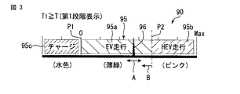
表示部90は、メータの背景をなす背景表示面95と、アクセル操作量に応じて移動するインジケータ96とを有している。背景表示面95は、後述するように、エンジン14が停止していた時間に応じて、色を3段階に変化させることができるようになっている。この背景表示面95は、例えばバックライトを備えた液晶パネル等のディスプレイパネルを用いてもよいし、あるいは複数の発光ダイオード(LED)などを用いてもよい。 The
図3〜図5は表示部90の一例を示している。図3は背景表示面95が第1段階の表示(通常表示)を行っている状態を示している。図4は第2段階の表示、図5は第3段階の表示(注意換気表示)である。これらの表示については後に詳しく説明する。 3 to 5 show an example of the
背景表示面95は、モータのみの走行であることを表示するモータ走行ゾーン95aと、ハイブリッド走行であることを表示するハイブリッド走行ゾーン95bと、回生電流が発生していることを示すチャージゾーン95cなどを含んでいる。インジケータ96は、アクセル操作量に応じて、背景表示面95上をゾーン幅方向(矢印Aで示す方向)に移動する。 The
例えばこのハイブリッド車両10が停止し、アクセル操作量がゼロのとき、インジケータ96は背景表示面95のゼロ点位置P1で止まっている。アクセルペダル50が操作され、アクセル操作量が所定値以下のときにはモータ11,12のみによって走行するモータ走行モードとなり、その際に表示部90のインジケータ96はモータ走行ゾーン95aに位置している。アクセル操作量が所定値を越えると、エンジン14の併用によるハイブリッド走行に移行するとともに、表示部90のインジケータ96がハイブリッド走行ゾーン95bに移動する。 For example, when the
このハイブリッド車両10の走行中に、アクセル操作を止めて減速すると、モータ11,12に回生電流が発生するため、バッテリ13に回生電流が供給されるとともに、表示部90のインジケータ96がチャージゾーン95cに移動することにより、バッテリ13に充電がなされていることが判る。 If the accelerator operation is stopped and the vehicle is decelerated while the
さらにこの表示部90は、バッテリ13の残り容量(充電率)に応じて、モータ走行ゾーン95aとハイブリッド走行ゾーン95bとの境界P2の位置を、ゾーン幅方向に変化させることができるようになっている。すなわちバッテリ13の残り容量(充電率)が十分あるときには、境界P2が図3〜図5に示す標準位置に設定され、バッテリ13の残り容量(充電率)が所定値よりも下がったときに、境界P2を矢印B方向に移動させることにより、モータ走行ゾーン95aの範囲を狭くするようになっている。 Further, the
運転者はこの表示部90を見ることにより、モータ走行を行いたいときにはインジケータ96がモータ走行ゾーン95aに入るようにアクセル操作を行うことができる。また、ハイブリッド走行を行いたいときには、インジケータ96がハイブリッド走行ゾーン95bに入るようにアクセル操作量を大きくする。このように運転者の意思により、モータ走行とハイブリッド走行とを選択することができる。 By looking at the
運転者は燃料の消費を節約するために、あるいは静粛性を求めるために、アクセル操作量を小さくしてモータ走行のみを行うことができる。このためモータ走行のみが長期間にわたって行われる可能性があり、その場合には、エンジン14が長期間作動しない状況が生じる。そこで本実施形態の表示装置15は、エンジン14が長時間作動しなかったとき、運転者にモータ走行からハイブリッド走行に移ることを促すように背景表示面95を変化させる。 In order to save fuel consumption or to obtain quietness, the driver can perform only motor running with a small accelerator operation amount. For this reason, there is a possibility that only motor travel is performed for a long period of time, and in this case, a situation occurs in which the
以下に本実施形態の表示装置15の処理の流れについて、図6のフローチャートを参照して説明する。
まずステップST1において、メインスイッチがオンされたか否かが判断される。メインスイッチがオフであれば、ステップST2においてタイマ時間Tが保持される。メインスイッチがオンであればステップST3に進み、アクセルポジションセンサ51によってアクセル操作量が検出される。さらにステップST4に進むことにより、バッテリECU58によってバッテリ13の充電率が検出される。The processing flow of the display device 15 of the present embodiment will be described below with reference to the flowchart of FIG.
First, in step ST1, it is determined whether or not the main switch is turned on. If the main switch is off, the timer time T is held in step ST2. If the main switch is on, the process proceeds to step ST3, and the accelerator operation amount is detected by the
ステップST5において、エンジン14が作動しているか否かが判断される。エンジン14が作動している場合には、ステップST6においてタイマ時間Tをゼロにする。エンジン14が作動していない場合にはステップST7に進み、タイマ時間Tを加算(カウントアップ)する。すなわちこのステップST7は、「ハイブリッド車両がモータのみで走行しエンジンが停止した状態が継続した時間をカウントする手段」として機能する。 In step ST5, it is determined whether the
ステップST8では、バッテリ充電状態に応じて、背景表示面95のモータ走行ゾーン95aとハイブリッド走行ゾーン95bの広さの割合を決定する。すなわち、バッテリ13の残量(充電率)が所定値以上の場合には、図3〜図5に示すようにモータ走行ゾーン95aを広くとり、ハイブリッド走行ゾーン95bを狭くする。バッテリ13の残量が少なくなると、モータ走行ゾーン95aとハイブリッド走行ゾーン95bとの境界P2を矢印B方向に移動させることにより、モータ走行ゾーン95aを狭くするとともに、ハイブリッド走行ゾーン95bを広くする。すなわちこのステップST8は、「バッテリの充電率に応じてモータ走行ゾーンの幅を変化させる手段」として機能し、バッテリの充電率が下がると前記モータ走行ゾーンを狭くするようにしている。 In step ST8, the ratio of the width of the
さらにステップST9に進むことにより、アクセル操作量に応じてインジケータ96を移動させる。例えばアクセル操作量が小さいときには、インジケータ96をモータ走行ゾーン95a内に位置させる。アクセル操作量が大きくなると、インジケータ96をハイブリッド走行ゾーン95bに移動させる。このため運転者はインジケータ96の位置を見ることにより、モータ走行中かハイブリッド走行中かを知ることができる。すなわちこのステップST9は、「アクセル操作量に応じてインジケータをモータ走行ゾーンとハイブリッド走行ゾーンとの間で移動させる手段」として機能する。 Further, by proceeding to step ST9, the
そしてステップST10において、前記タイマ時間Tが第1の基準値T1と比較され、TがT1以下の場合(T1≧T)には、ステップST11において前記背景表示面95を第1段階の表示とする。すなわちこのステップST10は、「カウントされたエンジン停止時間が所定の基準値以内のときに表示部の背景表示面を第1段階の表示とする手段」として機能する。 In step ST10, the timer time T is compared with the first reference value T1. If T is equal to or less than T1 (T1 ≧ T), the
図3は、背景表示面95が第1段階の表示をなしている状態を示している。例えはモータ走行ゾーン95aが薄緑色で表示され、ハイブリッド走行ゾーン95bがピンクで表示される。チャージゾーン95cは水色で表示される。この第1段階の表示が行われるときには、エンジン14をあえて作動させる必要がないため、背景表示面95は運転者にハイブリッド走行を促す表示とはせず、一般的な表示(通常表示)とする。 FIG. 3 shows a state in which the
前記ステップST10において、TがT1を越えた場合(T>T1)には、ステップST12に進む。ステップST12では、タイマ時間Tが第2の基準値T2と比較され、TがT2以下の場合(T2≧T>T1)にはステップST13に進み、背景表示面95を第2段階の表示に切換える。すなわちこのステップST13は、「エンジン停止時間が前記基準値を越えたときに背景表示面を第2段階の表示に切換える手段」として機能する。 In step ST10, when T exceeds T1 (T> T1), the process proceeds to step ST12. In step ST12, the timer time T is compared with the second reference value T2, and if T is T2 or less (T2 ≧ T> T1), the process proceeds to step ST13, and the
図4は、背景表示面95が第2段階の表示をなしている状態を示している。例えばモータ走行ゾーン95aが緑色で表示され、ハイブリッド走行ゾーン95bが黄色で表示される。チャージゾーン95cは水色で表示されている。この第2段階の表示を行う時点では、エンジン14が停止してから中程度の時間が経過しているため、そろそろハイブリッド走行を行ってもよい旨を運転者に促す表示(中程度の注意喚起表示)としている。 FIG. 4 shows a state in which the
前記ステップST12において、TがT2を越えた場合(T>T2)にはステップST14に進み、背景表示面95を第3段階の表示に切換える。
図5は、背景表示面95が第3段階の表示をなしている状態を示している。例えはモータ走行ゾーン95aがピンクで表示され、ハイブリッド走行ゾーン95bが薄緑で表示される。チャージゾーン95cは水色で表示されている。第3段階の表示を行う時点では、エンジン14の停止状態が長く続いているため、運転者にハイブリッド走行を促す表示(注意喚起表示)としている。In step ST12, when T exceeds T2 (T> T2), the process proceeds to step ST14, and the
FIG. 5 shows a state in which the
よって運転者は、アクセル操作量を大きくし、インジケータ96をハイブリッド走行ゾーン95bに移動させることにより、エンジン14を作動させることが可能となる。このためエンジン14が長期間停止した状態のままになることによる問題を回避でき、エンジン14や補機類のコンディションを良好に維持することができる。 Therefore, the driver can operate the
このように本実施形態の表示装置15を備えたハイブリッド車両10によれば、モータ11,12のみによる走行が長期間続いてエンジン14が作動していない状況が長期間続いた場合に、表示部90を通常表示以外の警告色で表示することにより、運転者にハイブリッド走行に移ることを促すことができ、エンジン14を作動させることが可能となる。 As described above, according to the
なお前記実施形態の場合には、第1段階の表示(通常表示)と第2段階の表示および第3段階の表示(注意喚起表示)でそれぞれ背景表示面95の色を変化させたが、色を変化させる代わりに、例えば各段階で記号や絵柄、文字等を異ならせる表示を行うなど、背景表示面95の形態に応じてハイブリッド走行を促してもよい。また第1段階の表示と第2段階の表示のみでもよく、要するにハイブリッド走行を促すことができる表示に切換えることができればよい。 In the case of the above embodiment, the color of the
また本発明を実施するに当たり、表示部の具体的な態様をはじめとして、ハイブリッド車両に搭載するエンジンやモータあるいはバッテリ等の構成や数および配置などの態様を種々に変更して実施できることは言うまでもない。 Moreover, when implementing this invention, it cannot be overemphasized that aspects, such as a structure, number, arrangement | positioning, etc. of an engine, a motor, a battery, etc. which are mounted in a hybrid vehicle can be changed variously including the specific aspect of a display part. .
10…ハイブリッド車両
11,12…モータ
13…バッテリ
14…エンジン
15…表示装置
90…表示部
91…メータECU(データ処理部)
95…背景表示面
95a…モータ走行ゾーン
95b…ハイブリッド走行ゾーン
96…インジケータDESCRIPTION OF
95 ...
Claims (4)
Translated fromJapanese運転者が目視可能な位置に設けられた表示部と、
該表示部を制御するためのデータ処理部とを有し、
前記表示部は、
モータ走行ゾーンとハイブリッド走行ゾーンとを含む背景表示面と、該背景表示面に対して移動可能なインジケータとを含み、
前記データ処理部は、
アクセル操作量に応じて前記インジケータを前記モータ走行ゾーンと前記ハイブリッド走行ゾーンとの間で移動させる手段と、
該ハイブリッド車両が前記モータのみで走行し前記エンジンが停止した状態が継続した時間をカウントする手段と、
前記カウントされたエンジン停止時間が所定の基準値以内のときに前記表示部の背景表示面を第1段階の表示とし、前記エンジン停止時間が前記基準値より大きい第2の基準値を越えたときに前記背景表示面を第3段階の表示に切換える手段と、
を具備し、
前記第1段階の表示における前記モータ走行ゾーンの前記背景表示面と前記第3段階の表示における前記ハイブリッド走行ゾーンの前記背景表示面とを互いに共通の第1背景表示とし、かつ、前記第1段階の表示における前記ハイブリッド走行ゾーンの前記背景表示面と前記第3段階の表示における前記モータ走行ゾーンの前記背景表示面とを互いに共通の第2背景表示とし、
前記第2背景表示における走行モードよりも前記第1背景表示における走行モードでの走行を促すよう前記第1背景表示が前記第2背景表示よりも走行を促すための注意喚起された表示となっていることを特徴とするハイブリッド車両の表示装置。A display device for a hybrid vehicle including a traveling motor, a driving battery, and an engine,
A display unit provided at a position where the driver can see;
A data processing unit for controlling the display unit,
The display unit
A background display surface including a motor travel zone and a hybrid travel zone, and an indicator movable relative to the background display surface,
The data processing unit
Means for moving the indicator between the motor travel zone and the hybrid travel zone in accordance with an accelerator operation amount;
Means for counting a time during which the hybrid vehicle travels only with the motor and the engine is stopped; and
When the counted engine stop time is within a predetermined reference value, the background display surface of the display unit is set to the first stage display, and when the engine stop time exceeds a second reference value greater than the reference value Means for switching the background display surface to a third stage display;
Comprising
The background display surface of the motor travel zone in the display of the first step and the background display surface of the hybrid travel zone in the display of the third step are set as a commonfirst background display, and the first step The background display surface of the hybrid travel zone in the display of the above and the background display surface of the motor travel zone in the display of the third stage as asecond background display common to each other,
The first background display is an alerted display for urging the vehicle to travel more than the second background display so as to encourage the vehicle to travel in the travel mode in the first background display rather than the travel mode in the second background display. display device for a hybrid vehicle, characterized inthat there.
前記エンジン停止時間が前記基準値を越えたときに前記背景表示面を第2段階の表示に切換える手段をさらに具備し、
前記カウントされたエンジン停止時間が第1の基準値よりも大きく前記第2の基準値以下のときに前記背景表示面を前記第2段階の表示とし、前記エンジン停止時間が前記第2の基準値を越えたときに前記背景表示面を前記第3段階の表示に切換えることを特徴とする請求項1または2に記載のハイブリッド車両の表示装置。The data processing unit
Means for switching the background display surface to a second stage display when the engine stop time exceeds the reference value;
When the counted engine stop time is greater than the first reference value and less than or equal to the second reference value, the background display surface is displayed in the second stage, and the engine stop time is the second reference value. 3. The display device for a hybrid vehicle according to claim 1, wherein the background display surface is switched to the display of the third stage when the value exceeds the threshold.
Priority Applications (1)
| Application Number | Priority Date | Filing Date | Title |
|---|---|---|---|
| JP2010002304AJP5407876B2 (en) | 2010-01-07 | 2010-01-07 | Display device for hybrid vehicle |
Applications Claiming Priority (1)
| Application Number | Priority Date | Filing Date | Title |
|---|---|---|---|
| JP2010002304AJP5407876B2 (en) | 2010-01-07 | 2010-01-07 | Display device for hybrid vehicle |
Publications (2)
| Publication Number | Publication Date |
|---|---|
| JP2011140275A JP2011140275A (en) | 2011-07-21 |
| JP5407876B2true JP5407876B2 (en) | 2014-02-05 |
Family
ID=44456455
Family Applications (1)
| Application Number | Title | Priority Date | Filing Date |
|---|---|---|---|
| JP2010002304AExpired - Fee RelatedJP5407876B2 (en) | 2010-01-07 | 2010-01-07 | Display device for hybrid vehicle |
Country Status (1)
| Country | Link |
|---|---|
| JP (1) | JP5407876B2 (en) |
Families Citing this family (8)
| Publication number | Priority date | Publication date | Assignee | Title |
|---|---|---|---|---|
| JP5906641B2 (en)* | 2011-09-29 | 2016-04-20 | スズキ株式会社 | Vehicle drive control device |
| JP2014227024A (en)* | 2013-05-22 | 2014-12-08 | トヨタ自動車株式会社 | Hybrid-vehicle display control device |
| JP6237656B2 (en)* | 2015-01-19 | 2017-11-29 | トヨタ自動車株式会社 | Vehicle system |
| JP6176264B2 (en) | 2015-01-19 | 2017-08-09 | トヨタ自動車株式会社 | Automated driving vehicle system |
| CN108883775B (en)* | 2016-03-31 | 2021-09-07 | 本田技研工业株式会社 | Vehicle control system, vehicle control method, and storage medium |
| JP6966723B2 (en)* | 2017-05-18 | 2021-11-17 | 三菱自動車工業株式会社 | Hybrid vehicle display device |
| JP7410451B2 (en)* | 2018-08-02 | 2024-01-10 | 三菱自動車工業株式会社 | Hybrid vehicle display device |
| JP7615792B2 (en)* | 2021-03-16 | 2025-01-17 | スズキ株式会社 | Hybrid vehicle control device |
Family Cites Families (7)
| Publication number | Priority date | Publication date | Assignee | Title |
|---|---|---|---|---|
| JP2914059B2 (en)* | 1992-11-26 | 1999-06-28 | 日産自動車株式会社 | Hybrid electric vehicle |
| JP4156814B2 (en)* | 2001-01-10 | 2008-09-24 | 本田技研工業株式会社 | Vehicle meter device |
| JP2002349405A (en)* | 2001-05-29 | 2002-12-04 | Toyota Motor Corp | Automobile |
| JP4561650B2 (en)* | 2006-02-15 | 2010-10-13 | トヨタ自動車株式会社 | Hybrid vehicle |
| JP4735845B2 (en)* | 2006-09-25 | 2011-07-27 | マツダ株式会社 | Lighting control device for instrument panel for vehicle |
| JP4155321B2 (en)* | 2006-09-25 | 2008-09-24 | トヨタ自動車株式会社 | Hybrid vehicle display device, hybrid vehicle, and hybrid vehicle display method |
| JP2009113706A (en)* | 2007-11-08 | 2009-05-28 | Toyota Motor Corp | Hybrid vehicle |
- 2010
- 2010-01-07JPJP2010002304Apatent/JP5407876B2/ennot_activeExpired - Fee Related
Also Published As
| Publication number | Publication date |
|---|---|
| JP2011140275A (en) | 2011-07-21 |
Similar Documents
| Publication | Publication Date | Title |
|---|---|---|
| JP5407876B2 (en) | Display device for hybrid vehicle | |
| JP5316466B2 (en) | Display device | |
| US7898405B2 (en) | Vehicle information display and method | |
| CN105579311B (en) | The control device and control method of motor vehicle driven by mixed power | |
| JP5547699B2 (en) | Vehicle drive device | |
| JP5926182B2 (en) | Hybrid vehicle motor assistance based on user input | |
| US8718913B2 (en) | Vehicle efficiency information display and method | |
| JP4059286B2 (en) | Hybrid vehicle operation status display device | |
| CN105383499B (en) | Dump energy driving range energy compensating | |
| US20140142836A1 (en) | Cruising distance calculation apparatus for a hybrid vehicle | |
| KR102356538B1 (en) | Display method and display system in hybrid vehicle | |
| JP7149230B2 (en) | Vehicle system and hybrid vehicle | |
| CN103998306B (en) | Hybrid vehicle | |
| CN101900618A (en) | System for displaying power flow in a hybrid vehicle | |
| CN104627169B (en) | vehicle operation control based on load | |
| KR101724508B1 (en) | Limp home mode drive method for hybrid electric vehicle | |
| US9683875B2 (en) | Display device and method for a hybrid vehicle having such a display device | |
| JP6725880B2 (en) | Control device for hybrid vehicle | |
| CN103764427B (en) | Indicating device and indicating method for hybrid electric vehicle and hybrid electric vehicle with such indicating device | |
| JP2008174100A (en) | Hybrid vehicle operation state display device | |
| JP5906641B2 (en) | Vehicle drive control device | |
| JP6537464B2 (en) | Work car display device | |
| US9205827B2 (en) | Control apparatus and control method for vehicle | |
| JP5298173B2 (en) | Vehicle display device | |
| JP2007326432A (en) | Engine cooling system for hybrid automobile |
Legal Events
| Date | Code | Title | Description |
|---|---|---|---|
| A621 | Written request for application examination | Free format text:JAPANESE INTERMEDIATE CODE: A621 Effective date:20120112 | |
| A977 | Report on retrieval | Free format text:JAPANESE INTERMEDIATE CODE: A971007 Effective date:20130131 | |
| A131 | Notification of reasons for refusal | Free format text:JAPANESE INTERMEDIATE CODE: A131 Effective date:20130205 | |
| A521 | Request for written amendment filed | Free format text:JAPANESE INTERMEDIATE CODE: A523 Effective date:20130408 | |
| A131 | Notification of reasons for refusal | Free format text:JAPANESE INTERMEDIATE CODE: A131 Effective date:20130604 | |
| RD02 | Notification of acceptance of power of attorney | Free format text:JAPANESE INTERMEDIATE CODE: A7422 Effective date:20130719 | |
| A521 | Request for written amendment filed | Free format text:JAPANESE INTERMEDIATE CODE: A523 Effective date:20130805 | |
| TRDD | Decision of grant or rejection written | ||
| A01 | Written decision to grant a patent or to grant a registration (utility model) | Free format text:JAPANESE INTERMEDIATE CODE: A01 Effective date:20131008 | |
| A61 | First payment of annual fees (during grant procedure) | Free format text:JAPANESE INTERMEDIATE CODE: A61 Effective date:20131021 | |
| R151 | Written notification of patent or utility model registration | Ref document number:5407876 Country of ref document:JP Free format text:JAPANESE INTERMEDIATE CODE: R151 | |
| LAPS | Cancellation because of no payment of annual fees |