JP5406638B2 - Light source device and projector - Google Patents
Light source device and projectorDownload PDFInfo
- Publication number
- JP5406638B2 JP5406638B2JP2009200267AJP2009200267AJP5406638B2JP 5406638 B2JP5406638 B2JP 5406638B2JP 2009200267 AJP2009200267 AJP 2009200267AJP 2009200267 AJP2009200267 AJP 2009200267AJP 5406638 B2JP5406638 B2JP 5406638B2
- Authority
- JP
- Japan
- Prior art keywords
- light
- light source
- phosphor layer
- green phosphor
- source device
- Prior art date
- Legal status (The legal status is an assumption and is not a legal conclusion. Google has not performed a legal analysis and makes no representation as to the accuracy of the status listed.)
- Active
Links
Images


Classifications
- G—PHYSICS
- G03—PHOTOGRAPHY; CINEMATOGRAPHY; ANALOGOUS TECHNIQUES USING WAVES OTHER THAN OPTICAL WAVES; ELECTROGRAPHY; HOLOGRAPHY
- G03B—APPARATUS OR ARRANGEMENTS FOR TAKING PHOTOGRAPHS OR FOR PROJECTING OR VIEWING THEM; APPARATUS OR ARRANGEMENTS EMPLOYING ANALOGOUS TECHNIQUES USING WAVES OTHER THAN OPTICAL WAVES; ACCESSORIES THEREFOR
- G03B21/00—Projectors or projection-type viewers; Accessories therefor
- G03B21/14—Details
- G03B21/20—Lamp housings
- G03B21/2006—Lamp housings characterised by the light source
- G03B21/2033—LED or laser light sources
- G03B21/204—LED or laser light sources using secondary light emission, e.g. luminescence or fluorescence
Landscapes
- Physics & Mathematics (AREA)
- Engineering & Computer Science (AREA)
- Multimedia (AREA)
- Optics & Photonics (AREA)
- General Physics & Mathematics (AREA)
- Projection Apparatus (AREA)
- Non-Portable Lighting Devices Or Systems Thereof (AREA)
Description
Translated fromJapanese本発明は、蛍光ホイールを備えた光源装置と、該光源装置を備えたプロジェクタに関する。 The present invention relates to a light source device including a fluorescent wheel and a projector including the light source device.
今日、パーソナルコンピュータの画面やビデオ画像、さらに、メモリカード等に記憶されている画像データによる画像等をスクリーンに投影する画像投影装置としてのデータプロジェクタが多用されている。このプロジェクタは、光源から射出された光をDMD(デジタル・マイクロミラー・デバイス)と呼ばれるマイクロミラー表示素子、又は、液晶板に集光させ、スクリーン上にカラー画像を表示させるものである。 2. Description of the Related Art Today, data projectors are frequently used as image projection apparatuses that project a screen of a personal computer, a video image, an image based on image data stored in a memory card or the like onto a screen. This projector focuses light emitted from a light source on a micromirror display element called DMD (digital micromirror device) or a liquid crystal plate, and displays a color image on a screen.
このようなプロジェクタにおいて、従来は高輝度の放電ランプを光源とするものが主流であったが、近年、光源装置の発光素子として発光ダイオード(LED)やレーザーダイオード(LD)、あるいは、有機EL等の半導体発光素子を用いる開発や提案が多々なされている。 Conventionally, in such projectors, a projector using a high-intensity discharge lamp as a light source has been mainstream. However, in recent years, a light emitting diode (LED), a laser diode (LD), an organic EL, or the like is used as a light emitting element of a light source device. Many developments and proposals using such semiconductor light emitting devices have been made.
例えば、特開2004−220015号公報(特許文献1)では、発光素子を備えた光源装置において、光量の増大を図るために発光素子をマトリクス状に配置した光源装置が提案されている。しかしながら、特許文献1の発明は、発光素子の輝点が増えるため、発光面積と立体角の積で表される光源のエテンデューの値が、表示素子の面積と立体角の積で表される表示素子のエテンデューの値よりも大きくなり、各発光ダイオードから射出される光の利用効率が低くなるという問題点があった。 For example, Japanese Patent Laid-Open No. 2004-220015 (Patent Document 1) proposes a light source device in which light emitting elements are arranged in a matrix in order to increase the amount of light in a light source device including light emitting elements. However, in the invention of
このような問題を解決するため、発光面積が小さな蛍光体層に励起光を照射し、蛍光体層から射出された蛍光発光光を光源光として利用する提案がなされている。(特許文献2、特許文献3)。 In order to solve such a problem, proposals have been made to irradiate a phosphor layer having a small light emitting area with excitation light and to use the fluorescent light emitted from the phosphor layer as light source light. (
プロジェクタでは、高輝度、高強度の光を射出可能な光源装置が求められる。上述した特許文献2及び特許文献3のように、蛍光体層に励起光を照射し、蛍光体層から射出された蛍光発光光を光源光として利用する光源装置では、励起光の光量を増やすことにより高輝度且つ高強度の光を射出することができる。しかしながら、励起光の光量を増やすために複数の励起光源を使用した場合、発熱量の増加、電気消費量の増加に繋がり、また、プロジェクタ本体の大型化にも繋がる。 In projectors, a light source device capable of emitting light with high brightness and high intensity is required. In the light source device that irradiates the phosphor layer with excitation light and uses the fluorescent emission light emitted from the phosphor layer as light source light as in
そこで、本発明は、蛍光体層に所定波長帯域の励起光を照射した場合において、発光強度が高くなるように蛍光体層の蛍光体含有重量濃度及び蛍光体層の膜厚を決定することで、励起光の光量を増加させることなく高輝度、高強度の光源光を射出可能な光源装置と、この光源装置を備えたプロジェクタを提供することを目的としている。 Therefore, the present invention determines the phosphor-containing weight concentration of the phosphor layer and the thickness of the phosphor layer so that the emission intensity becomes high when the phosphor layer is irradiated with excitation light of a predetermined wavelength band. An object of the present invention is to provide a light source device capable of emitting high-luminance and high-intensity light source light without increasing the amount of excitation light, and a projector including the light source device.
本発明の光源装置は、所定波長帯域光を射出する励起光源と、該励起光源からの射出光を励起光として所定波長帯域の蛍光発光光を射出する蛍光体層を少なくとも一つ以上備えた発光板と、を備え、前記蛍光体層は、蛍光体と、該蛍光体が均一に散りばめられたバインダと、から形成され、前記発光板には前記蛍光体層として少なくとも緑色蛍光体層が形成され、該緑色蛍光体層における緑色蛍光体の前記蛍光体層に対する含有重量濃度は、60%乃至85%とされ、前記発光板は、前記緑色蛍光体層が敷設されたセグメントと、前記励起光源からの射出光を指向性の弱い拡散光に変換する拡散領域としてのセグメントと、が周方向に並設された蛍光ホイールとされ、赤色波長帯域光を射出する発光素子としての赤色発光ダイオードを有し、前記蛍光ホイールから射出される蛍光発光光及び拡散光と、前記発光素子からの射出光と、を所定の一面に集光させる集光光学系を備えたことを特徴とする。また、本発明の光源装置は、所定波長帯域光を射出する励起光源と、該励起光源からの射出光を励起光として所定波長帯域の蛍光発光光を射出する蛍光体層を少なくとも一つ以上備えた発光板と、を備え、前記蛍光体層は、蛍光体と、バインダと、から形成され、前記発光板には前記蛍光体層として少なくとも緑色蛍光体層が形成され、該緑色蛍光体層における緑色蛍光体の前記蛍光体層に対する含有重量濃度は、60%乃至85%とされ、前記発光板は、前記緑色蛍光体層と、前記励起光源からの励起光を受けて赤色波長帯域の蛍光発光光を射出する赤色蛍光体層と、からなる蛍光発光領域としてのセグメントと、前記励起光源からの射出光を指向性の弱い拡散光に変換する拡散領域としてのセグメントと、が周方向に並設された蛍光ホイールとされ、前記蛍光ホイールからの蛍光発光光及び拡散光を所定の一面に集光させる集光光学系を備えたことを特徴とする。
A light source device of the present invention includes an excitation light source that emits light of a predetermined wavelength band, and a light emission that includes at least one phosphor layer that emits fluorescence emission light of a predetermined wavelength band using the light emitted from the excitation light source as excitation light. The phosphor layer is formed of a phosphor and a binder in which the phosphor is uniformly dispersed, and at least a green phosphor layer is formed on the light-emitting plate as the phosphor layer. The content weight concentration of the green phosphor in the green phosphor layer with respect to the phosphor layer is 60% to 85%, and thelight emitting plate includes a segment in which the green phosphor layer is laid, and the excitation light source. And a segment as a diffusion region that converts the emitted light into diffuse light with weak directivity, and a fluorescent wheel arranged in parallel in the circumferential direction, and has a red light emitting diode as a light emitting element that emits light in the red wavelength band , A fluorescence light and diffuse light emitted from the serial luminescent wheel, characterized inthat a, the light emitted from the light emitting element with a predetermined condensing optical system for condensing on one side.The light source device of the present invention includes at least one excitation light source that emits light of a predetermined wavelength band and at least one phosphor layer that emits fluorescence emission light of a predetermined wavelength band using the light emitted from the excitation light source as excitation light. The phosphor layer is formed of a phosphor and a binder, and the phosphor plate has at least a green phosphor layer formed as the phosphor layer. The content weight concentration of the green phosphor with respect to the phosphor layer is 60% to 85%, and the light-emitting plate receives the excitation light from the green phosphor layer and the excitation light source and emits fluorescence in the red wavelength band. A red phosphor layer that emits light, and a segment as a fluorescent light emitting region, and a segment as a diffusion region that converts the emitted light from the excitation light source into diffuse light with low directivity are juxtaposed in the circumferential direction Fluorescent Hui It is a le, characterized by comprising a fluorescence light and condensing optical system for condensing the diffused light into a predetermined one side from the luminescent wheel.
また、本発明の光源装置において、前記励起光源は、青色波長帯域光を射出する固体発光素子であることを特徴とする。 In the light source device of the present invention, the excitation light source is a solid-state light emitting element that emits blue wavelength band light.
さらに、本発明の光源装置において、前記緑色蛍光体層の膜厚は、100μm乃至300μmとされていることを特徴とする。 Further, in the light source device of the present invention, the green phosphor layer has a thickness of 100 μm to 300 μm.
なお、本発明の光源装置において、前記緑色蛍光体層における緑色蛍光体の前記蛍光体層に対する含有重量濃度は、70%乃至80%とすることが好適である。 In the light source device of the present invention, it is preferable that the content concentration of the green phosphor in the green phosphor layer with respect to the phosphor layer is 70% to 80%.
また、本発明の光源装置において、前記緑色蛍光体層の膜厚は、150μm乃至200μmとすることが好適である。 In the light source device of the present invention, it is preferable that the green phosphor layer has a thickness of 150 μm to 200 μm.
そして、本発明の光源装置において、前記緑色蛍光体層の緑色蛍光体は、セリウム賦活ガーネット構造蛍光体であり、蛍光発光光における波長のピークが520nmから540nmの範囲であることを特徴とする。 In the light source device of the present invention, the green phosphor of the green phosphor layer is a cerium-activated garnet structure phosphor, and the wavelength peak in the fluorescence emission light is in the range of 520 nm to 540 nm.
また、本発明の光源装置において、前記励起光源は、波長のピークが430nm乃至460nmの範囲とされた青色波長帯域光を射出する青色レーザーダイオードであることを特徴とする。 In the light source device of the present invention, the excitation light source is a blue laser diode that emits blue wavelength band light having a wavelength peak in a range of 430 nm to 460 nm.
本発明のプロジェクタは、光源装置と、光源側光学系と、導光装置と、表示素子と、投影側光学系と、プロジェクタ制御手段と、を備え、前記光源装置は、上述したような光源装置であり、前記導光装置の入射面上に光源光が集光されるように配置されていることを特徴とする。 The projector according to the present invention includes a light source device, a light source side optical system, a light guide device, a display element, a projection side optical system, and a projector control means, and the light source device is a light source device as described above. The light source light is arranged so as to be condensed on the incident surface of the light guide device.
本発明によれば、蛍光体層に所定波長帯域の励起光を照射した場合において、発光強度が高くなるように蛍光体層の蛍光体含有重量濃度及び蛍光体層の膜厚を決定することで、励起光の光量を増加させることなく高輝度、高強度の光源光を射出可能な光源装置と、この光源装置を備えることにより高輝度かつ明度の高い投影が可能なプロジェクタを提供することができる。 According to the present invention, when the phosphor layer is irradiated with excitation light of a predetermined wavelength band, the phosphor-containing weight concentration of the phosphor layer and the thickness of the phosphor layer are determined so that the emission intensity becomes high. A light source device capable of emitting high-luminance and high-intensity light source light without increasing the amount of excitation light, and a projector capable of projecting with high luminance and high brightness can be provided by including this light source device. .
以下、本発明を実施するための形態について述べる。本発明のプロジェクタ10は、光源装置63と、光源側光学系62と、導光装置75と、表示素子51と、投影側光学系90と、プロジェクタ制御手段と、を備え、光源装置63は、導光装置75の入射面上に光源光が集光するように配置されている。 Hereinafter, modes for carrying out the present invention will be described. The
そして、光源装置63は、青色波長帯域光を射出する励起光源72と、発光板としての蛍光ホイール71と、赤色波長帯域光を射出する発光素子74としての赤色発光ダイオードと、蛍光ホイール71からの射出光及び発光素子74からの射出光を所定の一面、つまり、導光装置75の入射面上に集光する集光光学系と、を備える。 The
この蛍光ホイール71は、励起光源72からの射出光を励起光として緑色波長帯域の蛍光発光光を射出する緑色蛍光体層4が敷設された蛍光発光領域2と、励起光源72からの射出光を指向性の弱い拡散光に変換する拡散領域1と、が周方向に並設されてなる。 The
そして、緑色蛍光体層4は、緑色蛍光体と、該緑色蛍光体が均一に散りばめられたバインダと、から形成されている。また、緑色蛍光体層4は、励起光源72からの射出光が緑色蛍光体層4に照射された場合に緑色蛍光体層4から射出される蛍光発光光の発光強度が高くなるように、蛍光体層に対する緑色蛍光体の含有重量濃度を決定されている。具体的には、蛍光体層に対する緑色蛍光体の含有重量濃度は、70%乃至80%の濃度とされている。 The
また、緑色蛍光体層4は、励起光源72からの射出光が緑色蛍光体層4に照射された場合に緑色蛍光体層4から射出される蛍光発光光の発光強度が高くなるように膜厚が決定されている。具体的には、緑色蛍光体層4の膜厚は、150μm乃至200μmとされている。 Further, the
そして、本発明の光源装置63において、緑色蛍光体層4は、蛍光発光光における波長のピークが520nmから540nmの範囲である、セリウム賦活ガーネット構造蛍光体を用いて形成されている。また、励起光源72は、波長のピークが430nm乃至460nmの範囲とされた青色波長帯域光を射出する青色レーザーダイオードとされている。 In the
以下、本発明の実施例を図に基づいて詳説する。図1は、プロジェクタ10の外観斜視図である。なお、本実施例において、左右とは投影方向に対しての左右方向を示し、前後とは光線束の進行方向に対しての前後方向を示す。 Hereinafter, embodiments of the present invention will be described in detail with reference to the drawings. FIG. 1 is an external perspective view of the
プロジェクタ10は、図1に示すように、略直方体形状であって、本体ケースの前方の側板とされる正面パネル12の側方に投影口を覆うレンズカバー19を有するとともに、この正面パネル12には複数の排気孔17を設けている。さらに、図示しないがリモートコントローラからの制御信号を受信するIr受信部を備えている。 As shown in FIG. 1, the
また、本体ケースである上面パネル11にはキー/インジケータ部37が設けられ、このキー/インジケータ部37には、電源スイッチキーや電源のオン又はオフを報知するパワーインジケータ、投影のオン、オフを切りかえる投影スイッチキー、光源装置や表示素子又は制御回路等が過熱したときに報知をする過熱インジケータ等のキーやインジケータが配置されている。 In addition, a key /
さらに、本体ケースの背面には、背面パネルにUSB端子や画像信号入力用のD−SUB端子、S端子、RCA端子等を設ける入出力コネクタ部及び電源アダプタプラグ等の各種端子20が設けられている。なお、図示しない本体ケースの側板である右側パネル14、及び、図1に示した側板である左側パネル15の下部近傍には、各々複数の吸気孔18が形成されている。 In addition, on the back of the main body case, there are provided
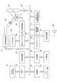
次に、プロジェクタ10のプロジェクタ制御手段について図2のブロック図を用いて述べる。プロジェクタ制御手段は、制御部38、入出力インターフェース22、画像変換部23、表示エンコーダ24、表示駆動部26等から構成され、入出力コネクタ部21から入力された各種規格の画像信号は、入出力インターフェース22、システムバス(SB)を介して画像変換部23で表示に適した所定のフォーマットの画像信号に統一するように変換された後、表示エンコーダ24に出力される。 Next, projector control means of the
また、表示エンコーダ24は、入力された画像信号をビデオRAM25に展開記憶させた上でこのビデオRAM25の記憶内容からビデオ信号を生成して表示駆動部26に出力する。 The
表示駆動部26は、表示素子制御手段として機能するものであり、表示エンコーダ24から出力された画像信号に対応して適宜フレームレートで空間的光変調素子(SOM)である表示素子51を駆動するものであり、光源装置63から射出された光線束を光源側光学系を介して表示素子51に照射することにより、表示素子51の反射光で光像を形成し、後述する投影側光学系90を介して図示しないスクリーンに画像を投影表示する。なお、この投影側光学系90の可動レンズ群97は、レンズモータ45によりズーム調整やフォーカス調整のための駆動が行われる。 The display drive unit 26 functions as display element control means, and drives the
また、画像圧縮伸長部31は、再生モード時にメモリカード32に記録された画像データを読み出し、一連の動画を構成する個々の画像データを1フレーム単位で伸長し、この画像データを画像変換部23を介して表示エンコーダ24に出力し、メモリカード32に記憶された画像データに基づいて動画等の表示を可能とする処理を行なう。なお、本実施例のプロジェクタ10では、プロジェクタ10の筐体にカードスロットルを設けてこのカードスロットルにメモリカード32を差し込む構成とする場合や、入出力コネクタ部21にUSBメモリとしてのメモリカード32を差し込む構成とする場合等がある。 The image compression /
制御部38は、プロジェクタ10内の各回路の動作制御を司るものであって、CPUや各種セッティング等の動作プログラムを固定的に記憶したROM及びワークメモリとして使用されるRAM等により構成されている。 The
本体ケースの上面パネル11に設けられるメインキー及びインジケータ等により構成されるキー/インジケータ部37の操作信号は、直接に制御部38に送出され、リモートコントローラからのキー操作信号は、Ir受信部35で受信され、Ir処理部36で復調されたコード信号が制御部38に出力される。 An operation signal of a key /
なお、制御部38にはシステムバス(SB)を介して音声処理部47が接続されている。この音声処理部47は、PCM音源等の音源回路を備えており、投影モード及び再生モード時には音声データをアナログ化し、スピーカ48を駆動して拡声放音させる。 Note that an
また、制御部38は、光源制御手段としての光源制御回路41を制御しており、この光源制御回路41は、画像生成時に要求される所定波長帯域光が光源装置63から射出されるように、光源装置63を制御する。さらに、制御部38は、冷却ファン駆動制御回路43に光源装置63等に設けた複数の温度センサによる温度検出を行わせ、この温度検出の結果から冷却ファンの回転速度を制御させている。また、制御部38は、冷却ファン駆動制御回路43にタイマー等によりプロジェクタ本体の電源OFF後も冷却ファンの回転を持続させる、或いは、温度センサによる温度検出の結果によってはプロジェクタ本体の電源をOFFにする等の制御も行う。 Further, the
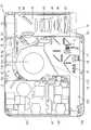
次に、このプロジェクタ10の内部構造について述べる。図3は、プロジェクタ10の内部構造を示す平面模式図である。プロジェクタ10には、図3に示すように、右側パネル14の近傍に電源回路ブロック101等を取付けた電源制御回路基板102が配置され、略中央にはシロッコファンタイプのブロア110が配置され、このブロア110の近傍に制御回路基板103が配置され、正面パネル12の近傍には光源装置63が配置され、左側パネル15の近傍には光学系ユニット70が配置されている。 Next, the internal structure of the
また、プロジェクタ10は、筐体内を区画用隔壁120により背面パネル13側の吸気側空間室121と正面パネル12側の排気側空間室122とに気密に区画されており、ブロア110は、吸込み口111が吸気側空間室121に位置し排気側空間室122と吸気側空間室121の境界に吐出口113が位置するように配置されている。 Further, the
光学系ユニット70は、光源装置63の近傍に位置する照明側ブロック78と、背面パネル13側に位置する画像生成ブロック79と、照明側ブロック78と左側パネル15との間に位置する投影側ブロック80との3つのブロックから構成された略コの字形状である。 The
この照明側ブロック78は、光源装置63から射出された光を画像生成ブロック79が備える表示素子51に導光する光源側光学系62の一部を備えている。この照明側ブロック78が有する光源側光学系62としては、光源装置63から射出された光線束を均一な強度分布の光束とする導光装置75や、導光装置75を透過した光を集光する集光レンズ等がある。 The
画像生成ブロック79は、光源側光学系62として、導光装置75から射出された光線束の光軸方向を変更する光軸変更ミラー76と、この光軸変更ミラー76により反射した光を表示素子51に集光させる複数枚の集光レンズと、これらの集光レンズを透過した光線束を表示素子51に所定の角度で照射する照射ミラー84と、を有している。さらに、画像生成ブロック79は、表示素子51とするDMDを備え、この表示素子51の背面パネル13側には表示素子51を冷却するための表示素子冷却装置53が配置されて、表示素子51が高温となることを防止している。 The
投影側ブロック80は、表示素子51で反射されて画像を形成する光をスクリーンに放出する投影側光学系90のレンズ群を有している。この投影側光学系90としては、固定鏡筒に内蔵する固定レンズ群93と可動鏡筒に内蔵する可動レンズ群97とを備えてズーム機能を備えた可変焦点型レンズとされ、レンズモータにより可動レンズ群97を移動させることによりズーム調整やフォーカス調整を可能としている。 The projection-
次に、本実施例のプロジェクタ10における光源装置63について述べる。図4は、光源装置63の平面模式図である。光源装置63は、図4に示すように、導光装置75の中心軸と光軸が平行となるように配置された複数の励起光源72と、励起光源72の前方に配置された複数のコリメータレンズ149と、コリメータレンズ149を透過した光線束の光軸方向を90度変換する反射ミラー群150と、を備える。 Next, the
また、光源装置63は、反射ミラー群150で反射した励起光の光軸と回転軸が平行となるように励起光の光軸上に配置された蛍光ホイール71と、蛍光ホイール71を回転駆動するホイールモータ73を備えている。さらに、光源装置63は、励起光源72から励起光を射出する際の光軸方向と光軸が平行となるように配置された発光素子74としての赤色光源と、蛍光ホイール71から射出される光線束の光軸及び発光素子74から射出された光線束の光軸を一致させて所定の一面に集光する集光光学系と、を備えてなる。 In addition, the
励起光源72は、複数の青色レーザー発光器が平面状に配列されてなり、青色波長帯域のレーザー光を励起光として蛍光ホイール71に射出するとともに、光源装置63における青色波長帯域光として蛍光ホイール71に射出する。また、コリメータレンズ149は、励起光源72における複数の青色レーザー発光器の前方において、各青色レーザー発光器からの射出光を指向性が増した平行光として前方に射出する。さらに、反射ミラー群150は、複数の短冊状の反射ミラーが階段状に配列されてなり、励起光源72からの射出光の光軸を90度変換するように反射する。 The
蛍光ホイール71は、図5に示すように、円形の発光板であって、ホイールモータ73によって回転を制御される。この蛍光ホイール71は、励起光源72からの射出光を拡散する拡散領域1としてのセグメントと、蛍光発光領域2としてのセグメントと、が周方向に並設されてなる。この拡散領域1は、ガラス等の透光性の高い部材によって形成されており、表面にサンドブラスト加工等によって微細凹凸が施されている。そして、拡散領域1に照射された励起光源72からの射出光は、指向性の高いレーザー光から指向性の低い拡散光に変換されて透過する。 As shown in FIG. 5, the
蛍光発光領域2は、金属材料等の表面に銀蒸着等によって反射面が施され、この反射面の表面にスパッタによってフッ化マグネシウム(MgF2)等の透明の保護膜が形成され、この保護膜の表面に緑色蛍光体層4が敷設されている。この緑色蛍光体層4は、耐熱性が高くかつ透光性の高いシリコン樹脂等のバインダと、このバインダに均一に散りばめられた緑色蛍光体と、から形成されている。また、緑色蛍光体は、セリウム賦活ガーネット構造蛍光体であり、Y3(Al,Ga)5O12:Ce3+を使用することが好適である。The fluorescent
この緑色蛍光体層4は、緑色蛍光体のバインダに対する含有重量濃度によって、及び、蛍光体の膜厚によって、同一の励起光を照射した場合であっても発光強度に差が生じる。図6は、複数の膜厚において、横軸に含有重量濃度をとり、縦軸に蛍光体の発光強度をとったグラフである。図6においては、含有重量濃度の単位は重量%とし、発光強度の単位は任意であるためarbitrary units(a.u.)としている。また、膜厚は、100μm、150μm、170μm、200μmの4種類としている。 Even when the
緑色蛍光体層4は、図6に示すように、含有重量濃度が75%前後の位置に発光強度のピークがあり、含有重量濃度を75%前後まであげた場合には発光強度も略含有重量濃度に比例して上がる。また、発光強度は、このピークを過ぎると徐々に下がり始める。 As shown in FIG. 6, the
このような現象において、含有重量濃度が低い場合に発光強度が落ちるのは、励起光を吸収して発光する蛍光体の絶対的な量が少ないためである。よって、含有重量濃度が低い場合は、緑色蛍光体層4に照射された励起光源72からの射出光の中で、蛍光体に照射されずに外部に出て行く光が多く、励起光源72から射出される光の利用効率が下がる。 In such a phenomenon, the emission intensity decreases when the content weight concentration is low because the absolute amount of the phosphor that emits light by absorbing the excitation light is small. Therefore, when the content weight concentration is low, in the emitted light from the
また、含有重量濃度が高すぎる場合に発光強度が落ちるのは、図7に示すように、蛍光体が510nm近傍までの波長帯域光を吸収して発光する特性を持っているため、蛍光体が蛍光発光した光の中で460nm乃至520nmの波長帯域光が他の蛍光体に照射されると、当該他の蛍光体において励起光として吸収されてしまい、蛍光体層から外部に射出される蛍光発光光の量が減るためである。よって、含有重量濃度が高すぎる場合は、蛍光体による蛍光発光光が蛍光体層の内部で吸収されてしまい、蛍光発光光の利用効率が下がることとなる。なお、図7は、横軸に波長をとり、縦軸に蛍光体の発光強度をとったグラフである。 In addition, when the concentration by weight is too high, the emission intensity decreases, as shown in FIG. 7, because the phosphor has a characteristic of absorbing and emitting light in the wavelength band up to near 510 nm. When light having a wavelength band of 460 nm to 520 nm is irradiated to other phosphors among the fluorescently emitted light, the other phosphors are absorbed as excitation light and emitted from the phosphor layer to the outside. This is because the amount of light is reduced. Therefore, when the content weight concentration is too high, the fluorescent light emitted by the fluorescent material is absorbed inside the fluorescent material layer, and the utilization efficiency of the fluorescent light is lowered. FIG. 7 is a graph in which the horizontal axis indicates the wavelength and the vertical axis indicates the emission intensity of the phosphor.
このようなセリウム賦活ガーネット構造蛍光体の特性から、励起光源72からの射出光の利用効率を高め、かつ、蛍光発光光の利用効率を高めることで発光強度を高めるためには、含有重量濃度が60%乃至85%、特に70%乃至80%とすることが好適であることがわかる。よって、本実施例の緑色蛍光体層4は、緑色蛍光体の蛍光体層に対する含有重量濃度を75%前後のものとしている。 From the characteristics of such a cerium-activated garnet structure phosphor, in order to increase the light emission intensity from the
また、緑色蛍光体層4の膜厚に関しては、図6のグラフに示すように、170μm前後の膜厚とした場合の発光強度が最も高い。このように膜厚によって発光強度が変化するのは、膜厚が薄すぎる場合、緑色蛍光体層4に照射された励起光源72からの射出光の中で蛍光体に照射されずに外部に出て行く光が多くなるために発光強度が下がる。一方、膜厚が厚すぎる場合、蛍光発光光が緑色蛍光体層4内部で他の蛍光体に吸収される確率が高くなり、外部に射出される蛍光発光光の光量が少なくなるため発光強度が下がる。よって、蛍光体層の膜厚は、厚すぎても薄すぎても発光強度が落ちるため、100μm乃至300μm、特に150μm乃至200μmとするのが好適である。よって、本実施例の緑色蛍光体層4は、膜厚を170μmとしている。 Regarding the film thickness of the
この緑色蛍光体層4における蛍光体の製法について述べる。この緑色蛍光体は、まず原料となる酸化イットリウム(Y2O3)、酸化アルミニウム(Al2O3)、酸化ガリウム(Ga2O3)、酸化セリウム(CeO2)を、Y:Al:Ga:Ce=2.98:3:2:0.02のモル比率で配合し、さらに、結晶成長を促進する触媒としてフッ化バリウムを蛍光体原料に対して50モル%で配合し、ポリエチレン容器に原料とエタノールを入れ、200rpm回転で5時間混合する。次に、混合した原料をろ過した後に乾燥させ、アルミナ容器に入れて4%水素還元雰囲気内で1500度、4時間の焼成を行う。そして、最後に触媒やその他の不純物を除去するために2基底の硝酸溶液で1時間攪拌し、純水で洗浄を行って乾燥することにより生成する。A method for manufacturing the phosphor in the
発光素子74は、赤色発光ダイオード等の赤色波長帯域光を射出する赤色光源とされている。そして、この赤色光源は、励起光源72と蛍光ホイール71との間の位置において、励起光源72から励起光を射出する際の光軸方向と赤色光源からの射出光の光軸とが平行になるよう配置されている。 The
そして、集光光学系は、複数のミラーによるミラー群151、複数の凸レンズによる凸レンズ群153、凸レンズやメニスカスレンズを組み合わせて集光レンズとした複数の当該集光レンズによる集光レンズ群155、導光装置入射レンズ154から構成される。 The condensing optical system includes a
ミラー群151は、反射ミラー群150で反射した励起光の光軸と発光素子74の光軸とが直交する位置に配置された第一ミラー151aと、蛍光ホイール71の裏面側であって導光装置75の中心軸の延長線と反射ミラー群150で反射した励起光の光軸の延長線とが交差する位置に配置された第二ミラー151bと、赤色光源の光軸上に配置された第三ミラー151cと、第三ミラー151cで反射した赤色波長帯域光の光軸と導光装置75の中心軸の延長線とが交差する位置に配置された第四ミラー151dと、を備える。 The
第一ミラー151aは、励起光源72及び赤色光源からの射出光を透過し、蛍光ホイール71で発光した蛍光光を反射するダイクロイックミラーとされている。また、第二ミラー151bは、反射ミラーとされ、蛍光ホイール71を拡散透過した励起光源72からの射出光の光軸を導光装置75の中心軸と一致させる。第三ミラー151cは、反射ミラーとされ、赤色光源からの射出光、及び、蛍光ホイール71で発光した蛍光光を第四ミラー151dへ反射させる。第四ミラー151dは、第二ミラー151bによって反射された光線束を透過し、第三ミラー151cによって反射された光線束を反射するダイクロイックミラーとされている。 The
また、集光光学系としての凸レンズ群153は、励起光源72と第一ミラー151aとの間に配置された第一凸レンズ153aと、第二ミラー151bと第四ミラー151dとの間に配置された第二凸レンズ153bと、第一ミラー151aと第三ミラー151cとの間に配置された第三凸レンズ153cと、第三ミラー151cと第四ミラー151dとの間に配置された第四凸レンズ153dと、を備える。 A
さらに、集光光学系としての集光レンズ群155は、赤色光源の近傍、及び、蛍光ホイール71の表裏両面近傍であって励起光源72からの射出光の光軸上に配置されており、赤色光源や蛍光ホイール71からの射出光を集光する。また、集光光学系としての導光装置入射レンズ154は、導光装置75の近傍に配置されており、光源装置63からの射出光を導光装置75の入射面に集光する。 Further, the condensing
そして、このような光源装置63において、励起光源72から射出され反射ミラー群150で反射された青色レーザー光は、第一凸レンズ153aによって集光された後、第一ミラー151aを透過し、集光レンズ群155によって蛍光ホイール71の蛍光反射領域や拡散領域に照射される。 In such a
また、励起光源72から射出され蛍光発光領域2の緑色蛍光体層4に照射された光線束は、励起光として蛍光体を励起し、蛍光体は所定波長帯域の光を発光する。さらに、励起光源72から射出され蛍光ホイール71の拡散領域に照射された光線束は、拡散して指向性の強いコヒーレント光から指向性の弱いインコヒーレント光に性質を変換され、インコヒーレント光の青色波長帯域光として蛍光ホイール71の裏面側から射出される。 The light bundle emitted from the
また、赤色光源から射出された赤色波長帯域光は、集光レンズ群155によって集光されて第一ミラー151aを透過し、蛍光ホイール71から励起光源72側へ射出された蛍光発光光は、集光レンズ群155によって集光されて第一ミラー151aに照射される。そして、第一ミラー151aを透過した赤色波長帯域光、及び、第一ミラー151aで反射した蛍光発光光は、第三凸レンズ153cや第四凸レンズ153dによって集光されるとともに、第三ミラー151c及び第四ミラー151dで反射し、導光装置入射レンズ154によって導光装置75の入射面に集光されて導光装置75内に入射する。 The red wavelength band light emitted from the red light source is condensed by the
さらに、蛍光ホイール71を拡散透過した青色波長帯域光は、集光レンズ群155によって集光されて第二ミラー151bに照射され、第二ミラー151bで反射し、第二凸レンズ153bで集光され、第四ミラー151dを透過した後、導光装置入射レンズ154によって導光装置75の入射面に集光されて導光装置75内に入射する。 Further, the blue wavelength band light diffused and transmitted through the
そして、導光装置75に入射した光源光は、導光装置75内で均一強度の光線束にされて光軸変更ミラー76に照射され、光軸変更ミラー76で反射して光学系ユニット70の画像生成ブロック79に入射し、表示素子51で投影光に変換されて投影側光学系90に入射し、投影側光学系90で拡大されてスクリーン等に投影される。 The light source light incident on the
本実施例の光源装置63における緑色蛍光体層4は、励起光源72からの射出光が緑色蛍光体層4に照射された場合、緑色蛍光体層4から射出される蛍光発光光の発光強度が高くなるように、蛍光体層に対する緑色蛍光体の含有重量濃度が決定されている。これにより、励起光源72からの射出光の光量を増加させることなく、蛍光発光光の光量を増やすことができ、また、蛍光体層内における蛍光発光光の吸収量を低減できるため、蛍光発光光の利用効率を高めることもできる。 In the
また、本実施例の光源装置63では、緑色蛍光体層4における緑色蛍光体の蛍光体層に対する含有重量濃度を60%乃至85%の濃度としている。このように、蛍光体の含有重量濃度に関して多少の幅を持たせることにより、蛍光体層の生成にかかるコストと蛍光発光光の光量とのバランスを吟味して蛍光体層の生成ができることとなる。 In the
そして、励起光源72として青色波長帯域光を射出する固体発光素子を用いることにより、励起光源72からの射出光を励起光として利用できるとともに、励起光源72からの射出光を青色波長帯域の光源光としても利用できるため、青色蛍光体層や青色光源を別途用意する必要がなくなり、光源装置63の小型化を図ることができる。 Then, by using a solid-state light emitting element that emits blue wavelength band light as the
また、本実施例の光源装置63における緑色蛍光体層4は、励起光源72からの射出光が緑色蛍光体層4に照射された場合、緑色蛍光体層4から射出される蛍光発光光の発光強度が高くなるように、緑色蛍光体層4の膜厚が決定されている。これにより、励起光源72からの射出光の光量を増加させることなく、蛍光発光光の光量を増やすことができ、また、励起光が無駄なく蛍光体に照射されるため、励起光の利用効率を高めることもできる。 In addition, the
さらに、本実施例の光源装置63では、緑色蛍光体層4の膜厚を100μm乃至300μmとしている。このように、蛍光体層の膜厚に関して多少の幅を持たせることにより、蛍光体層の生成にかかるコストと蛍光発光光の光量とのバランスや、蛍光体の含有重量濃度とのバランス等を吟味して蛍光体層の生成ができることとなる。 Furthermore, in the
また、緑色蛍光体層4における緑色蛍光体の含有重量濃度を70%乃至80%の濃度とすることにより、緑色蛍光体層4が、図6に示したように、最も発光強度の高い蛍光体の含有重量濃度となるため、蛍光発光光の利用効率をより高めることができることとなる。 Further, by setting the content weight concentration of the green phosphor in the
さらに、緑色蛍光体層4の膜厚を150μm乃至200μmとすることにより、緑色蛍光体層4が、図6に示したように、最も発光強度の高い膜厚となるため、緑色蛍光体層4内での蛍光発光光の吸収が最小限に抑えられ、また、緑色蛍光体層4に照射された励起光の中で緑色蛍光体に照射されることなく外部に出て行く光の量も低減することができ、励起光の利用効率を高めることもできる。 Further, by setting the thickness of the
そして、緑色蛍光体層4の緑色蛍光体として、青色波長帯域の励起光に対して発光強度の高い物質であるセリウム賦活ガーネット構造蛍光体を用いることにより、緑色波長帯域光の光量を増加させることができる。 Then, as the green phosphor of the
また、励起光源72として青色レーザーダイオードを用いることにより、エネルギーが高く、かつ、指向性の高い青色波長帯域光を蛍光ホイール71に照射することができ、緑色蛍光体を効率よく励起することができる。さらに、蛍光ホイール71において拡散させることにより、青色波長帯域の光源光も容易に生成できることとなる。 In addition, by using a blue laser diode as the
さらに、本実施例の光源装置63は、赤色波長帯域光を生成するために独立した発光素子74としての赤色発光ダイオードを備えている。これにより、光量や明度の高い赤色波長帯域光を射出可能な光源装置63を提供できる。 Further, the
そして、プロジェクタ10においてこのような光源装置63を用いることにより、輝度及び明度の高い投影画像の投影が可能なプロジェクタ10を提供できることとなる。 Then, by using such a
なお、上述した実施例では、赤色に関して独立の発光素子74を設けているが、図8に示すように、蛍光ホイール71を、赤色蛍光体層5及び緑色蛍光体層4からなる蛍光発光領域2と、拡散領域1と、を周方向に並設することにより、蛍光ホイール71によって赤色、緑色、青色波長帯域の光を生成する構成とすることもできる。 In the above-described embodiment, the independent
このように蛍光ホイール71によって赤色、緑色、青色波長帯域の光を生成する構成とする場合、赤色蛍光体層5における赤色蛍光体は、ユーロピウム賦活窒化物蛍光体を用いることができる。また、赤色蛍光体層5の蛍光体層に対する含有重量濃度及び膜厚は、上述した実施例における緑色蛍光体層4と同様に、発光強度を実験により求め、この実験結果から発光強度が高くなる含有重量濃度及び膜厚を決定することにより、光量が多く明度の高い赤色波長帯域光を射出可能な光源装置63を提供できることとなる。 Thus, when it is set as the structure which produces | generates the light of a red, green, blue wavelength band with the
なお、このユーロピウム賦活窒化物蛍光体の製法としては、原料の窒化ストロンチウム(Sr3N2)、窒化カルシウム(Ca3N2)、窒化アルミニウム(AlN)、窒化ケイ素(Si3N4)、酸化ユーロピウム(Eu2O3)を、窒素雰囲気内でSr:Ca:Al:Si:Eu=0.75:0.25:1.0:1.0:0.015のモル比で配合し、遊星ボールミルで混合する。そして、混合した原料を窒化ホウ素容器に入れ、9気圧窒素雰囲気中で1900度、4時間の焼成を行うことにより生成することができる。In addition, as a manufacturing method of this europium activation nitride fluorescent substance, raw material strontium nitride (Sr3 N2 ), calcium nitride (Ca3 N2 ), aluminum nitride (AlN), silicon nitride (Si3 N4 ), oxidation Europium (Eu2 O3 ) is blended in a nitrogen atmosphere at a molar ratio of Sr: Ca: Al: Si: Eu = 0.75: 0.25: 1.0: 1.0: 0.015, and planets Mix with a ball mill. And it can produce | generate by putting the mixed raw material into a boron nitride container, and baking at 1900 degree | times for 4 hours in 9 atmosphere nitrogen atmosphere.
また、このように蛍光ホイール71で赤色、緑色、青色波長帯域の光を生成する構成とした光源装置63では、図4に示した第一ミラー151aを青色透過、赤色及び緑色反射の特性を持つダイクロイックミラーとすることで、導光装置75の入射面に赤色、緑色、青色波長帯域の光を集光することができる。 Further, in the
なお、本発明は、蛍光体層における蛍光体の含有重量濃度及び膜厚を、実験データから発光強度が高くなる数値を求め、この数値に従って決定することを特徴とする。よって、本発明は、以上の実施例に限定されるものでなく、発明の要旨を逸脱しない範囲で自由に変更、改良が可能である。 The present invention is characterized in that the content concentration and the film thickness of the phosphor in the phosphor layer are determined according to the numerical values obtained from the experimental data obtained by increasing the emission intensity. Therefore, the present invention is not limited to the above embodiments, and can be freely changed and improved without departing from the gist of the invention.
1 拡散領域 2 蛍光発光領域
4 緑色蛍光体層 5 赤色蛍光体層
10 プロジェクタ 11 上面パネル
12 正面パネル 13 背面パネル
14 右側パネル 15 左側パネル
17 排気孔 18 吸気孔
19 レンズカバー 20 各種端子
21 入出力コネクタ部 22 入出力インターフェース
23 画像変換部 24 表示エンコーダ
25 ビデオRAM 26 表示駆動部
31 画像圧縮伸長部 32 メモリカード
35 Ir受信部 36 Ir処理部
37 キー/インジケータ部 38 制御部
41 光源制御回路 43 冷却ファン駆動制御回路
45 レンズモータ 47 音声処理部
48 スピーカ 51 表示素子
53 表示素子冷却装置 62 光源側光学系
63 光源装置 70 光学系ユニット
71 蛍光ホイール 72 励起光源
73 ホイールモータ 74 発光素子
75 導光装置 76 光軸変更ミラー
78 照明側ブロック 79 画像生成ブロック
80 投影側ブロック 84 照射ミラー
90 投影側光学系 93 固定レンズ群
97 可動レンズ群 101 電源回路ブロック
102 電源制御回路基板 103 制御回路基板
110 ブロア 111 吸込み口
113 吐出口 120 区画用隔壁
121 吸気側空間室 122 排気側空間室
149 コリメータレンズ 150 反射ミラー群
151 ミラー群 151a 第一ミラー
151b 第二ミラー 151c 第三ミラー
151d 第四ミラー 153 凸レンズ群
153a 第一凸レンズ 153b 第二凸レンズ
153c 第三凸レンズ 153d 第四凸レンズ
154 導光装置入射レンズ 155 集光レンズ群1
4
10
12
14
17
19
21 I / O connector 22 I / O interface
23
25 Video RAM 26 Display driver
31 Image compression /
35
37 Key /
41 Light
45
48
53 Display
63
71
73
75
78
80
90 Projection side
97
102 Power supply
110
113
121
149
151
151b
151d
153a First
153c Third
154 Light guiding
Claims (9)
Translated fromJapanese前記蛍光体層は、蛍光体と、バインダと、から形成され、
前記発光板には前記蛍光体層として少なくとも緑色蛍光体層が形成され、該緑色蛍光体層における緑色蛍光体の前記蛍光体層に対する含有重量濃度は、60%乃至85%とされ、
前記発光板は、前記緑色蛍光体層が敷設されたセグメントと、前記励起光源からの射出光を指向性の弱い拡散光に変換する拡散領域としてのセグメントと、が周方向に並設された蛍光ホイールとされ、
赤色波長帯域光を射出する発光素子としての赤色発光ダイオードを有し、
前記蛍光ホイールから射出される蛍光発光光及び拡散光と、前記発光素子からの射出光と、を所定の一面に集光させる集光光学系を備えていることを特徴とする光源装置。An excitation light source that emits light of a predetermined wavelength band, and a light emitting plate that includes at least one phosphor layer that emits fluorescence emission light of a predetermined wavelength band using the light emitted from the excitation light source as excitation light,
The phosphor layer is formed of a phosphor and a binder,
At least a green phosphor layer is formed as the phosphor layer on the light emitting plate, and the content concentration of the green phosphor in the green phosphor layer with respect to the phosphor layer is 60% to 85%,
The light emitting plate is a fluorescent light in which a segment in which the green phosphor layer is laid and a segment as a diffusion region for converting light emitted from the excitation light source into diffuse light having low directivity are arranged in parallel in the circumferential direction. With wheels,
It has a red light emitting diode as a light emitting element that emits red wavelength band light,
A light source device comprising: acondensing optical system that condenses fluorescent light emitted and diffused light emitted from the fluorescent wheel and light emitted from the light emitting element on a predetermined surface .
前記蛍光体層は、蛍光体と、バインダと、から形成され、The phosphor layer is formed of a phosphor and a binder,
前記発光板には前記蛍光体層として少なくとも緑色蛍光体層が形成され、該緑色蛍光体層における緑色蛍光体の前記蛍光体層に対する含有重量濃度は、60%乃至85%とされ、At least a green phosphor layer is formed as the phosphor layer on the light emitting plate, and the content concentration of the green phosphor in the green phosphor layer with respect to the phosphor layer is 60% to 85%,
前記発光板は、前記緑色蛍光体層と、前記励起光源からの励起光を受けて赤色波長帯域の蛍光発光光を射出する赤色蛍光体層と、からなる蛍光発光領域としてのセグメントと、前記励起光源からの射出光を指向性の弱い拡散光に変換する拡散領域としてのセグメントと、が周方向に並設された蛍光ホイールとされ、The light-emitting plate includes a segment as a fluorescent light-emitting region including the green phosphor layer, a red phosphor layer that receives excitation light from the excitation light source and emits fluorescence emission light in a red wavelength band, and the excitation A segment as a diffusion region that converts light emitted from a light source into diffuse light with low directivity, and a fluorescent wheel arranged in parallel in the circumferential direction,
前記蛍光ホイールからの蛍光発光光及び拡散光を所定の一面に集光させる集光光学系を備えたことを特徴とする光源装置。A light source apparatus comprising: a condensing optical system that condenses fluorescent light emitted from the fluorescent wheel and diffused light on a predetermined surface.
前記光源装置は、請求項1乃至請求項8のいずれかに記載の光源装置であり、前記導光装置の入射面上に光源光が集光されるように配置されていることを特徴とするプロジェクタ。
A light source device, a light source side optical system, a light guide device, a display element, a projection side optical system, and a projector control means,
The light source device is the light source device according to any one ofclaims 1 to 8 , wherein the light source device is disposed on the incident surface of the light guide device so as to be condensed. projector.
Priority Applications (2)
| Application Number | Priority Date | Filing Date | Title |
|---|---|---|---|
| JP2009200267AJP5406638B2 (en) | 2009-08-31 | 2009-08-31 | Light source device and projector |
| US12/872,173US8337027B2 (en) | 2009-08-31 | 2010-08-31 | Light source unit and projector |
Applications Claiming Priority (1)
| Application Number | Priority Date | Filing Date | Title |
|---|---|---|---|
| JP2009200267AJP5406638B2 (en) | 2009-08-31 | 2009-08-31 | Light source device and projector |
Publications (2)
| Publication Number | Publication Date |
|---|---|
| JP2011053320A JP2011053320A (en) | 2011-03-17 |
| JP5406638B2true JP5406638B2 (en) | 2014-02-05 |
Family
ID=43624457
Family Applications (1)
| Application Number | Title | Priority Date | Filing Date |
|---|---|---|---|
| JP2009200267AActiveJP5406638B2 (en) | 2009-08-31 | 2009-08-31 | Light source device and projector |
Country Status (2)
| Country | Link |
|---|---|
| US (1) | US8337027B2 (en) |
| JP (1) | JP5406638B2 (en) |
Families Citing this family (57)
| Publication number | Priority date | Publication date | Assignee | Title |
|---|---|---|---|---|
| WO2011092841A1 (en) | 2010-01-29 | 2011-08-04 | Necディスプレイソリューションズ株式会社 | Illumination optical system and projector using same |
| JP4973962B2 (en)* | 2010-03-31 | 2012-07-11 | カシオ計算機株式会社 | Light source device and projector |
| JP2012014045A (en)* | 2010-07-02 | 2012-01-19 | Seiko Epson Corp | projector |
| JP5534331B2 (en)* | 2010-07-30 | 2014-06-25 | カシオ計算機株式会社 | Light source unit and projector |
| JP5445379B2 (en)* | 2010-07-30 | 2014-03-19 | セイコーエプソン株式会社 | projector |
| US8955985B2 (en)* | 2010-10-19 | 2015-02-17 | Nec Display Solutions, Ltd. | Lighting device and projection-type display device using same |
| WO2012066654A1 (en)* | 2010-11-17 | 2012-05-24 | Necディスプレイソリューションズ株式会社 | Light source apparatus, lighting apparatus, and projection-type display apparatus |
| EP2650727A4 (en)* | 2010-12-08 | 2014-05-21 | Nec Display Solutions Ltd | Lighting optical system and projection display device comprising same |
| EP2650728A4 (en)* | 2010-12-08 | 2014-05-07 | Nec Display Solutions Ltd | Lighting optical system and projection display device comprising same |
| JP2012141411A (en)* | 2010-12-28 | 2012-07-26 | Jvc Kenwood Corp | Light source device |
| TWI427397B (en)* | 2011-03-23 | 2014-02-21 | Delta Electronics Inc | Illumination system |
| JP5223941B2 (en)* | 2011-03-28 | 2013-06-26 | カシオ計算機株式会社 | Projection device |
| US9500935B2 (en)* | 2011-04-18 | 2016-11-22 | Nec Display Solutions, Ltd. | Projection image display device |
| US20120327374A1 (en)* | 2011-06-23 | 2012-12-27 | Panasonic Corporation | Illumination apparatus and projection display apparatus |
| WO2013008323A1 (en) | 2011-07-13 | 2013-01-17 | Necディスプレイソリューションズ株式会社 | Light source device and projection-type display device |
| JP5987382B2 (en)* | 2011-07-22 | 2016-09-07 | 株式会社リコー | LIGHTING DEVICE, PROJECTION DEVICE, AND METHOD FOR CONTROLLING PROJECTION DEVICE |
| TWI439793B (en)* | 2011-08-03 | 2014-06-01 | Hon Hai Prec Ind Co Ltd | Porjector light source apparatus |
| TWI440956B (en)* | 2011-08-17 | 2014-06-11 | Hon Hai Prec Ind Co Ltd | Porjector light source apparatus |
| CN102650811B (en)* | 2011-08-27 | 2016-01-27 | 深圳市光峰光电技术有限公司 | Projection system and its lighting device |
| US9075299B2 (en)* | 2011-08-27 | 2015-07-07 | Appotronics Corporation Limited | Light source with wavelength conversion device and filter plate |
| CN102955240A (en)* | 2011-08-29 | 2013-03-06 | 鸿富锦精密工业(深圳)有限公司 | Projector light source device |
| CN102955241A (en)* | 2011-08-29 | 2013-03-06 | 鸿富锦精密工业(深圳)有限公司 | Light source device of projector |
| TWI450021B (en)* | 2011-09-29 | 2014-08-21 | Acer Inc | Image generating device capable of improving luminous efficiency |
| CN103034035A (en)* | 2011-09-30 | 2013-04-10 | 中强光电股份有限公司 | Illumination system and projection device |
| JP5862938B2 (en)* | 2011-10-03 | 2016-02-16 | カシオ計算機株式会社 | Light source device and projector |
| TW201317701A (en)* | 2011-10-24 | 2013-05-01 | Hon Hai Prec Ind Co Ltd | Optical mechanical of projector |
| CN103076712B (en)* | 2011-10-26 | 2015-05-27 | 深圳市光峰光电技术有限公司 | Projection light source and projection device using same |
| CN103091954A (en)* | 2011-11-02 | 2013-05-08 | 鸿富锦精密工业(深圳)有限公司 | Projector Optical Mechanics |
| CN103207507B (en) | 2012-01-11 | 2015-07-08 | 中强光电股份有限公司 | Light source module and projection device |
| JP2013162020A (en) | 2012-02-07 | 2013-08-19 | Seiko Epson Corp | Wavelength conversion element, light source device, and projector |
| JP2013162021A (en) | 2012-02-07 | 2013-08-19 | Seiko Epson Corp | Wavelength conversion element, light source device, and projector |
| CN104808426A (en)* | 2012-04-10 | 2015-07-29 | 海信集团有限公司 | Projection display light source |
| JP5962904B2 (en) | 2012-04-26 | 2016-08-03 | パナソニックIpマネジメント株式会社 | Light source device and projection display device including the light source device |
| WO2013190778A1 (en) | 2012-06-21 | 2013-12-27 | パナソニック株式会社 | Light emitting device and projection device |
| DE102012211837A1 (en)* | 2012-07-06 | 2014-01-09 | Osram Gmbh | Illuminating device with luminous arrangement and laser |
| JP6171345B2 (en) | 2012-09-10 | 2017-08-02 | 株式会社リコー | Illumination light source device, projection device equipped with this illumination light source device, and control method of projection device |
| TWI452409B (en)* | 2012-12-14 | 2014-09-11 | Delta Electronics Inc | Light emitting module, optical excitation device and projector using the same |
| US20140204349A1 (en)* | 2013-01-18 | 2014-07-24 | Delta Electronics, Inc. | Illumination system and projection device comprising the same |
| JP6233687B2 (en)* | 2013-08-12 | 2017-11-22 | 株式会社リコー | Light source device and image projection device provided with the same |
| JP6056724B2 (en)* | 2013-09-30 | 2017-01-11 | ウシオ電機株式会社 | Fluorescent light source device |
| JP6299460B2 (en)* | 2013-10-16 | 2018-03-28 | セイコーエプソン株式会社 | projector |
| JP2015088636A (en)* | 2013-10-31 | 2015-05-07 | セイコーエプソン株式会社 | Fluorescent light-emitting element, light source device, and projector |
| JP6503710B2 (en) | 2013-12-27 | 2019-04-24 | 日本電気硝子株式会社 | Fluorescent wheel for projector, method of manufacturing the same, and light emitting device for projector |
| WO2015111145A1 (en)* | 2014-01-22 | 2015-07-30 | 日立マクセル株式会社 | Light source device and image display device using same |
| JP2015138168A (en) | 2014-01-23 | 2015-07-30 | セイコーエプソン株式会社 | Fluorescent light emitting device and projector |
| TWI561773B (en) | 2014-08-06 | 2016-12-11 | Delta Electronics Inc | Six-primary solid state illuminator and operating method using the same |
| JP6662069B2 (en)* | 2016-02-02 | 2020-03-11 | セイコーエプソン株式会社 | Light source device and projector |
| JP2017138573A (en)* | 2016-02-04 | 2017-08-10 | パナソニックIpマネジメント株式会社 | Phosphor wheel, light source device, and projection display device |
| CN107037677A (en)* | 2016-02-04 | 2017-08-11 | 松下知识产权经营株式会社 | Fluorophor wheel, light supply apparatus and projection type video display device |
| KR102595295B1 (en)* | 2016-08-12 | 2023-10-30 | 엘지전자 주식회사 | Projector |
| JP6977285B2 (en) | 2017-03-28 | 2021-12-08 | セイコーエプソン株式会社 | Wavelength converters, light source devices and projectors |
| JP7142205B2 (en) | 2017-08-08 | 2022-09-27 | パナソニックIpマネジメント株式会社 | Fluorescent plate, light source device, and projection display device |
| CN109283781B (en)* | 2018-11-23 | 2023-10-03 | 中山联合光电科技股份有限公司 | Projector light source device based on aperture compression |
| JP7277223B2 (en)* | 2019-04-02 | 2023-05-18 | スタンレー電気株式会社 | Light source device and projection device |
| CN110456603B (en)* | 2019-08-05 | 2024-10-18 | 深圳光维科技有限公司 | Projection display optical system |
| CN113603462B (en)* | 2021-07-20 | 2022-08-26 | 中国计量大学 | Ceramic-glass composite structure fluorescent color wheel, preparation method thereof and application thereof in laser display source |
| CN116750732B (en)* | 2023-06-30 | 2025-06-03 | 江苏博睿光电股份有限公司 | Preparation method of quasi-spherical nitride phosphor, quasi-spherical nitride phosphor and application thereof |
Family Cites Families (12)
| Publication number | Priority date | Publication date | Assignee | Title |
|---|---|---|---|---|
| TW383508B (en)* | 1996-07-29 | 2000-03-01 | Nichia Kagaku Kogyo Kk | Light emitting device and display |
| JP2004220015A (en) | 2002-12-26 | 2004-08-05 | Sanyo Electric Co Ltd | Lighting unit and projection video display device |
| JP4604458B2 (en)* | 2003-04-25 | 2011-01-05 | セイコーエプソン株式会社 | Projection display |
| JP4829470B2 (en)* | 2003-05-14 | 2011-12-07 | Necディスプレイソリューションズ株式会社 | Projection display |
| JP2006301114A (en)* | 2005-04-18 | 2006-11-02 | Sony Corp | Illumination device and picture display device |
| JP2007218956A (en)* | 2006-02-14 | 2007-08-30 | Sharp Corp | Projection type image display device |
| EP2133720A1 (en)* | 2006-03-29 | 2009-12-16 | Sony Deutschland Gmbh | Display apparatus with recombination of elementary spectral images using a rotation-controlled wheel |
| JP2008052070A (en)* | 2006-08-25 | 2008-03-06 | Samsung Electronics Co Ltd | Color wheel, visible light source, projection type image display device, and projection type image display method |
| JP2008134433A (en)* | 2006-11-28 | 2008-06-12 | Funai Electric Co Ltd | Projector |
| JP5105165B2 (en)* | 2007-12-18 | 2012-12-19 | カシオ計算機株式会社 | Light source device and projector |
| JP4678556B2 (en)* | 2009-03-17 | 2011-04-27 | カシオ計算機株式会社 | Light emitting device, light source device, and projector using the light source device |
| WO2011092841A1 (en)* | 2010-01-29 | 2011-08-04 | Necディスプレイソリューションズ株式会社 | Illumination optical system and projector using same |
- 2009
- 2009-08-31JPJP2009200267Apatent/JP5406638B2/enactiveActive
- 2010
- 2010-08-31USUS12/872,173patent/US8337027B2/enactiveActive
Also Published As
| Publication number | Publication date |
|---|---|
| US8337027B2 (en) | 2012-12-25 |
| JP2011053320A (en) | 2011-03-17 |
| US20110051102A1 (en) | 2011-03-03 |
Similar Documents
| Publication | Publication Date | Title |
|---|---|---|
| JP5406638B2 (en) | Light source device and projector | |
| JP5666865B2 (en) | Light source unit and projector | |
| JP4756403B2 (en) | Light source device and projector | |
| JP5406639B2 (en) | Light source device and projector | |
| JP5397684B2 (en) | Light source device and projector | |
| JP4711156B2 (en) | Light source device and projector | |
| CN102053467B (en) | Light source unit and projector | |
| CN102207669B (en) | Light source system and projector | |
| JP4900736B2 (en) | Light source device and projector | |
| JP5428078B2 (en) | Light source device and projector | |
| JP5656058B2 (en) | Light emitting unit and projector | |
| JP5327529B2 (en) | Light source device and projector | |
| TW201126256A (en) | Light source unit and projector | |
| JP2009259583A (en) | Light source unit and projector | |
| JP2013080055A (en) | Light source device and projector | |
| JP2011170363A (en) | Light source device and projector | |
| JP5783272B2 (en) | Light emitting unit and projector | |
| JP5445854B2 (en) | Light emitting unit and projector | |
| JP6086193B2 (en) | Light source device, lighting method of light source device, and projector | |
| JP6270012B2 (en) | Light source device, lighting method of light source device, and projector | |
| JP2016001310A (en) | Light source device and projector | |
| HK1152756B (en) | Light source unit and projector |
Legal Events
| Date | Code | Title | Description |
|---|---|---|---|
| A621 | Written request for application examination | Free format text:JAPANESE INTERMEDIATE CODE: A621 Effective date:20120828 | |
| A977 | Report on retrieval | Free format text:JAPANESE INTERMEDIATE CODE: A971007 Effective date:20130613 | |
| A131 | Notification of reasons for refusal | Free format text:JAPANESE INTERMEDIATE CODE: A131 Effective date:20130627 | |
| A521 | Request for written amendment filed | Free format text:JAPANESE INTERMEDIATE CODE: A523 Effective date:20130823 | |
| TRDD | Decision of grant or rejection written | ||
| A01 | Written decision to grant a patent or to grant a registration (utility model) | Free format text:JAPANESE INTERMEDIATE CODE: A01 Effective date:20131003 | |
| A61 | First payment of annual fees (during grant procedure) | Free format text:JAPANESE INTERMEDIATE CODE: A61 Effective date:20131101 | |
| R150 | Certificate of patent or registration of utility model | Ref document number:5406638 Country of ref document:JP Free format text:JAPANESE INTERMEDIATE CODE: R150 | |
| R250 | Receipt of annual fees | Free format text:JAPANESE INTERMEDIATE CODE: R250 | |
| R250 | Receipt of annual fees | Free format text:JAPANESE INTERMEDIATE CODE: R250 | |
| R250 | Receipt of annual fees | Free format text:JAPANESE INTERMEDIATE CODE: R250 | |
| R250 | Receipt of annual fees | Free format text:JAPANESE INTERMEDIATE CODE: R250 | |
| R250 | Receipt of annual fees | Free format text:JAPANESE INTERMEDIATE CODE: R250 | |
| R250 | Receipt of annual fees | Free format text:JAPANESE INTERMEDIATE CODE: R250 | |
| R250 | Receipt of annual fees | Free format text:JAPANESE INTERMEDIATE CODE: R250 | |
| R250 | Receipt of annual fees | Free format text:JAPANESE INTERMEDIATE CODE: R250 | |
| R250 | Receipt of annual fees | Free format text:JAPANESE INTERMEDIATE CODE: R250 |