JP5406412B2 - Moving lift device with anti-overturn system - Google Patents
Moving lift device with anti-overturn systemDownload PDFInfo
- Publication number
- JP5406412B2 JP5406412B2JP2013502488AJP2013502488AJP5406412B2JP 5406412 B2JP5406412 B2JP 5406412B2JP 2013502488 AJP2013502488 AJP 2013502488AJP 2013502488 AJP2013502488 AJP 2013502488AJP 5406412 B2JP5406412 B2JP 5406412B2
- Authority
- JP
- Japan
- Prior art keywords
- base frame
- bed
- rollover prevention
- post
- boom
- Prior art date
- Legal status (The legal status is an assumption and is not a legal conclusion. Google has not performed a legal analysis and makes no representation as to the accuracy of the status listed.)
- Active
Links
Images


Classifications
- A—HUMAN NECESSITIES
- A61—MEDICAL OR VETERINARY SCIENCE; HYGIENE
- A61G—TRANSPORT, PERSONAL CONVEYANCES, OR ACCOMMODATION SPECIALLY ADAPTED FOR PATIENTS OR DISABLED PERSONS; OPERATING TABLES OR CHAIRS; CHAIRS FOR DENTISTRY; FUNERAL DEVICES
- A61G7/00—Beds specially adapted for nursing; Devices for lifting patients or disabled persons
- A61G7/10—Devices for lifting patients or disabled persons, e.g. special adaptations of hoists thereto
- A61G7/1013—Lifting of patients by
- A61G7/1019—Vertical extending columns or mechanisms
- A—HUMAN NECESSITIES
- A61—MEDICAL OR VETERINARY SCIENCE; HYGIENE
- A61G—TRANSPORT, PERSONAL CONVEYANCES, OR ACCOMMODATION SPECIALLY ADAPTED FOR PATIENTS OR DISABLED PERSONS; OPERATING TABLES OR CHAIRS; CHAIRS FOR DENTISTRY; FUNERAL DEVICES
- A61G7/00—Beds specially adapted for nursing; Devices for lifting patients or disabled persons
- A61G7/10—Devices for lifting patients or disabled persons, e.g. special adaptations of hoists thereto
- A61G7/104—Devices carried or supported by
- A61G7/1046—Mobile bases, e.g. having wheels
- A—HUMAN NECESSITIES
- A61—MEDICAL OR VETERINARY SCIENCE; HYGIENE
- A61G—TRANSPORT, PERSONAL CONVEYANCES, OR ACCOMMODATION SPECIALLY ADAPTED FOR PATIENTS OR DISABLED PERSONS; OPERATING TABLES OR CHAIRS; CHAIRS FOR DENTISTRY; FUNERAL DEVICES
- A61G7/00—Beds specially adapted for nursing; Devices for lifting patients or disabled persons
- A61G7/10—Devices for lifting patients or disabled persons, e.g. special adaptations of hoists thereto
- A61G7/1049—Attachment, suspending or supporting means for patients
- A61G7/1057—Supported platforms, frames or sheets for patient in lying position
- A—HUMAN NECESSITIES
- A61—MEDICAL OR VETERINARY SCIENCE; HYGIENE
- A61G—TRANSPORT, PERSONAL CONVEYANCES, OR ACCOMMODATION SPECIALLY ADAPTED FOR PATIENTS OR DISABLED PERSONS; OPERATING TABLES OR CHAIRS; CHAIRS FOR DENTISTRY; FUNERAL DEVICES
- A61G7/00—Beds specially adapted for nursing; Devices for lifting patients or disabled persons
- A61G7/10—Devices for lifting patients or disabled persons, e.g. special adaptations of hoists thereto
- A61G7/1063—Safety means
- A61G7/1067—Safety means for adjustable bases
- A—HUMAN NECESSITIES
- A61—MEDICAL OR VETERINARY SCIENCE; HYGIENE
- A61G—TRANSPORT, PERSONAL CONVEYANCES, OR ACCOMMODATION SPECIALLY ADAPTED FOR PATIENTS OR DISABLED PERSONS; OPERATING TABLES OR CHAIRS; CHAIRS FOR DENTISTRY; FUNERAL DEVICES
- A61G2200/00—Information related to the kind of patient or his position
- A61G2200/30—Specific positions of the patient
- A61G2200/32—Specific positions of the patient lying
- A—HUMAN NECESSITIES
- A61—MEDICAL OR VETERINARY SCIENCE; HYGIENE
- A61G—TRANSPORT, PERSONAL CONVEYANCES, OR ACCOMMODATION SPECIALLY ADAPTED FOR PATIENTS OR DISABLED PERSONS; OPERATING TABLES OR CHAIRS; CHAIRS FOR DENTISTRY; FUNERAL DEVICES
- A61G2203/00—General characteristics of devices
- A61G2203/10—General characteristics of devices characterised by specific control means, e.g. for adjustment or steering
- A61G2203/14—Joysticks
Landscapes
- Health & Medical Sciences (AREA)
- Nursing (AREA)
- Life Sciences & Earth Sciences (AREA)
- Animal Behavior & Ethology (AREA)
- General Health & Medical Sciences (AREA)
- Public Health (AREA)
- Veterinary Medicine (AREA)
- Invalid Beds And Related Equipment (AREA)
Description
Translated fromJapanese本発明は移動用リフト装置に関し、より詳しくは、使用者が横たわっているベッド部を回転させるとき、重心位置の変化によってリフト装置が転覆することを防止する転覆防止システムを備える移動用リフト装置に関する。 The present invention relates to a moving lift device, and more particularly, to a moving lift device provided with a rollover prevention system that prevents a lift device from overturning due to a change in the center of gravity when a bed portion on which a user lies is rotated. .
一般的に、身体が不自由な患者や老弱者の場合、看病人または介護する者の看護を受けて生活をしている。その中で、重症の患者や老弱者など自力で動けない人の場合は、長距離の移動を行うためには車椅子または移動用ベッドを使用している。 In general, patients who are physically handicapped or elderly are living under the care of a nurse or caregiver. Among them, in the case of a person who cannot move by himself such as a serious patient or an elderly person, a wheelchair or a moving bed is used for long-distance movement.
ところで、移動用ベッドは動くことがきわめて難しい患者が使用することが普通であるが、このような患者を看病人が病床から移動用ベッドに移すことさえ容易ではないだけではなく、かえって患者や老弱者の重さによって看病人が腰を負傷することが頻繁に起きる。このため、最近、患者や老弱者の移動または乗降を助ける様々な移動用リフト装置が開発されている。 By the way, a moving bed is usually used by a patient who is extremely difficult to move, but it is not only easy for a caregiver to move such a patient from the bed to the moving bed. The caregiver frequently injures the lower back due to the weight of the weak. For this reason, recently, various lifting devices for movement that help the patient or the elderly move or get on and off have been developed.
一方、従来の移動用リフト装置は、単純に患者を乗り降させたり、ベッドに横たわっている患者を移動させたりする機能のみを備えているに過ぎず、移動用リフト装置が移動できる経路の制約が多かった。また、移動できる経路の制約があるため、移動用リフト装置が有っても、世話する看病人や介護する者の負傷の危険は相変わらず存在している。 On the other hand, the conventional moving lift device has only a function of simply getting on and off the patient or moving the patient lying on the bed, and restrictions on the path that the moving lift device can move. There were many. In addition, because there are restrictions on the routes that can be moved, even if there is a lift device for movement, there is still a risk of injury to the caregivers and caregivers who are cared for.
すなわち、ベッド部は患者を横たえるために一方に長い長手方向を有する。しかし、このような移動用リフト装置は、病院の廊下で向かい合ってくる者がいたり、狭いコーナーを通過したりするときに移動用リフト装置全体を回転させる必要があるので、移動用リフト装置を移動させる看病人および移動用リフト装置に乗せられた患者にとって不便であった。 That is, the bed portion has a long longitudinal direction on one side to lie the patient. However, such a moving lift device needs to rotate the entire moving lift device when there is a person who faces each other in a hospital corridor or when passing through a narrow corner. It was inconvenient for the nurses to be carried and the patients on the mobile lift device.
本発明は、上記のような従来の問題を解決するためになされたものであり、ベッド部のみの回転を可能とすることにより、移動が便利で、回転可能なベッド部を備えた移動用リフト装置を提供することを目的とする。 The present invention has been made in order to solve the conventional problems as described above, and is capable of rotating only by the bed portion, so that the movement is convenient and the moving lift having the rotatable bed portion is provided. An object is to provide an apparatus.
また、本発明は、ベッド部が回転して重心が変わっても、転覆するようなことがない安定した構造を有する回転可能なベッド部を備えた移動用リフト装置を提供することを他の目的とする。 Another object of the present invention is to provide a moving lift device having a rotatable bed portion having a stable structure that does not overturn even if the bed portion rotates and the center of gravity changes. And
上記目的を達成するための本発明の一実施の形態による転覆防止システムを備えた移動用リフト装置は、底面を構成するベースフレームと、このベースフレームから上方に所定長さ延びたポスト、およびこのポストによって支持され、使用者が横たわれるように水平に設けられたベッド部からなり、このベッド部は前記ベースフレームに対して回転および昇降可能に設けられた上部構造物と、ベッド部の回転に伴ってベースフレームに対するベッド部の高さを調節する転覆防止制御部とから構成されている。 In order to achieve the above object, a lift apparatus for movement having a rollover prevention system according to an embodiment of the present invention includes a base frame constituting a bottom surface, a post extending upward from the base frame by a predetermined length, and It consists of a bed part that is supported by a post and is horizontally provided so that a user lies down. This bed part can be rotated and raised with respect to the base frame, and the bed part can be rotated. Accordingly, the rollover prevention control unit adjusts the height of the bed portion with respect to the base frame.
上部構造物は、ベースフレームに対して回転可能に設けたポストと、このポストにそって昇降可能に設けたブームと、このブームに固定されたベッド部とを含んでいる。 The superstructure includes a post provided rotatably with respect to the base frame, a boom provided so as to be able to move up and down along the post, and a bed portion fixed to the boom.
転覆防止制御部は、ブームをポストに対して昇降させる高さ調節部を含み、ベッド部の回転角度によってベースフレームに対するブームの高さを調節する。 The rollover prevention control unit includes a height adjustment unit that raises and lowers the boom with respect to the post, and adjusts the height of the boom relative to the base frame according to the rotation angle of the bed unit.
高さ調節部は、ポスト内の内周面にねじ山が形成されたねじ孔がポストの長手方向にそって設けられ、ブーム内にねじ孔の長手方向にそって設けられ、ねじ孔のねじ山に螺合して回転により昇降するように外周面にねじ山が形成されたスクリューと、転覆防止制御部の制御によってスクリューを正方向または逆方向に回転させることによりポストに螺合したブームを昇降させる高さ調節モータとを含んでいる。 The height adjusting portion is provided with a screw hole having a thread formed on the inner peripheral surface of the post along the longitudinal direction of the post, and is provided along the longitudinal direction of the screw hole in the boom. A screw threaded on the outer periphery so that it can be screwed up and down by rotation and a boom screwed into the post by rotating the screw in the forward or reverse direction under the control of the rollover prevention control unit And a height adjusting motor that moves up and down.
ベースフレームの外側に選択的に伸縮して、ベースフレームを底面に対して移動可能に支持する少なくとも1つ以上の延長足部を有し、転覆防止制御部はベッド部の回転に伴って延長足部の伸縮量を調節することができる。 It has at least one extension leg that selectively expands and contracts outside the base frame and supports the base frame so as to be movable with respect to the bottom surface, and the rollover prevention control unit extends with the rotation of the bed part. The amount of expansion / contraction of the part can be adjusted.
転覆防止制御部は、延長足部をベースに対して伸縮させる伸縮駆動部を有し、ベッド部の回転角度に応じて延長足部の伸縮量を調節する。 The rollover prevention control unit has an expansion / contraction drive unit that expands and contracts the extension foot with respect to the base, and adjusts the expansion / contraction amount of the extension foot according to the rotation angle of the bed portion.
伸縮駆動部は、延長足部からベースフレーム側に延在し一面に歯が形成されたラックと、ベースフレームに固定され、ラックに噛み合って転覆防止制御部の制御によって正方向または逆方向に所定回数回転してラックを直線方向に移動させる伸縮調節モータとを含む。 The telescopic drive unit extends from the extended foot to the base frame side and has teeth formed on one side thereof. The telescopic drive unit is fixed to the base frame, meshes with the rack, and is controlled in the forward or reverse direction by the control of the rollover prevention control unit. An expansion / contraction adjustment motor that rotates a number of times and moves the rack in a linear direction.
本発明による回転可能なベッド部を備えた移動用リフト装置は、以下のような効果を有する。 The lift apparatus for movement provided with the rotatable bed part by this invention has the following effects.
第一に、ベッド部を支持するポストが回転可能であるので、ベースフレームの全体を回転させることなく、ベッド部のみを回転させることができ、狭い廊下やコーナーを通過するときにより容易である。 First, since the post supporting the bed portion is rotatable, only the bed portion can be rotated without rotating the entire base frame, which is easier when passing through a narrow corridor or corner.
第二に、ベッド部の回転に伴って転覆防止制御部により延長足部が伸張してベッド部により作用するモーメントを安定して支持するか、あるいはベッド部の高さが低くなってベッド部により作用するモーメント自体が小さくなることにより、移動用リフト装置の転覆事故を防止して患者の2次負傷を避けることができる。 Second, with the rotation of the bed part, the extension foot part is stretched by the rollover prevention control part to stably support the moment acting on the bed part, or the bed part is lowered and lowered by the bed part. By reducing the acting moment itself, it is possible to prevent a rollover accident of the moving lift device and avoid a secondary injury of the patient.
以下、上記目的を具体的に実現できる本発明の好ましい実施形態について添付図面を参照して詳細に説明する。なお、実施形態の説明において、同一または相当部分は同一名称および符合を付してその説明を省略する。 Hereinafter, preferred embodiments of the present invention capable of specifically realizing the above object will be described in detail with reference to the accompanying drawings. In the description of the embodiments, the same or corresponding parts are denoted by the same names and reference numerals, and the description thereof is omitted.
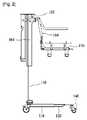
本発明の一実施の形態による転覆防止システムを備えた移動用リフト装置100(以下、‘移動用リフト装置’という)は、図1および図2に示すように、ベースフレーム110と、上部構造物112と、転覆防止制御部とを備えている。 As shown in FIGS. 1 and 2, a moving lift device 100 (hereinafter referred to as “moving lift device”) provided with a rollover prevention system according to an embodiment of the present invention includes a
ベースフレーム110は、この実施形態に係る移動用リフト装置100の底面を構成し、この底面が移動用リフト装置100のその他の構成要素を支持している。 The
このようなベースフレーム110は、図1に示すように、骨組構造から形成することができ、または所定の面積を有するパネル形態から形成することもできる。 As shown in FIG. 1, the
ベースフレーム110の外縁部の複数個所に延長足部(extending legs)120が設けられている。 Extending
それぞれの延長足部120は、ベースフレーム110から外方に延び、後述する伸縮駆動部により選択的に伸びたり縮んだりする。 Each
それぞれの延長足部120の先端部にはローラ140が設けられており、延長足部120およびベースフレーム110を底面に対して移動可能に支持する。 A
ベースフレーム110上には上部構造物112が設けられている。 An
上部構造物112は、ポスト150と、ベッド部170とを備えている。 The
ポスト150は、後述するベッド部170を床面から離間して支持するとともに、昇降可能に支持している。このようなポスト150は、ベッド部170をベースフレーム110から上方に離間した状態で支持するように上下方向に長手方向を有する。 The
ベッド部170は、老弱者および患者を横たえることができるように形成されており、容易な乗り降りができるために、ポスト150にそって上下方向に昇降させることによって高さ調節が可能である。 The
ベッド部170の下側には複数の移動輪が設けられており、床面での移動が容易である。 A plurality of moving wheels are provided on the lower side of the
ベッド部170は、ポスト150にそって昇降可能に形成されているが、このために、ポスト150とベッド部170の間にはブーム160が設けられている。 The
ブーム160は、図1および図8に示すように、後述する高さ調節部によりポスト150にそって昇降可能に設けられ、一側にベッド部170が固定されている。 As shown in FIGS. 1 and 8, the
ベッド部170は、着脱部182、第1アーム184および第2アーム186を介してブーム160に結合することにより支持されている。 The
着脱部182は、ブーム160に着脱可能に固定されている。 The attaching / detaching
第1アーム184は、着脱部182から一方に延び、ベッド部170が固定される。この実施形態では、図1および図2に示すように、第1アーム184が下方へと水平方向に延びており、水平に延びた部分にベッド部170の両側が結合されている。また、ベッド部170は第1ベッド172と第2ベッド174のように複数に分割して形成することができ、この場合、第1アーム184は一対設けられ、第1、第2ベッド172,174のそれぞれが一対の第1アーム184に回転可能にヒンジ結合されている。 The
第2アーム186は、第1アーム184からベッド部170と平行に結合され、その各両端には回転角度が調節可能なリンク188が設けられている。それぞれのリンク188の先端は、ベッド172,174の第1アーム184が回転可能に結合したところから所定間隔離間したところに回転可能に結合されている。これにより、第1ベッド172および第2ベッド174の角度調節が可能である。 The
ベッド部170には、患者や老弱者がベッド部170に横たわったり起き上がったりするときに握持できる第1把持部185が設けられている。また、第1把持部185は、ベッド部170が床面に置かれたとき、ベッド部170を押したり引いたりすることができるように形成されている。また、第1把持部185は回転可能に設けられており、必要時には反らすことができるので、患者や老弱者が横たわったり起き上がったりするときに邪魔にならない。 The
ブーム160またはポスト150には、保護者や看病人が移動用リフト装置100を押したり引いたりすることができるように第2把持部185が設けられている。 The
なお、ベッド部170は、図3に示すように、ベースフレーム110に対して水平方向に回転可能に形成されている。このために、この実施形態では、ポスト150の下端部がベースフレーム110に回転可能に結合されていることを例示している。 As shown in FIG. 3, the
もちろん、この発明はこれに限定されず、ベッド部が結合されたブームまたはブームに結合された着脱部が回転するように形成することもできる。 Of course, the present invention is not limited to this, and it can be formed such that the boom to which the bed portion is coupled or the detachable portion coupled to the boom is rotated.
したがって、ポスト150が回転可能であるので、ポスト150に設けられたブーム160およびベッド170は全てポスト150の回転に伴って回転することができる。したがって、廊下を移動中に向かい合ってくる者がいる時、狭い廊下のコーナーを回る時、あるいは幅狭い門を通過する時にも、移動用リフト装置100の全体を回転させることなく、ポスト150を回転させることのみでもベッド部170を回転させることができるので、より容易に最適の角度でベッド部170を回転させることができ、保護者や看病人の利便性が向上する。 Therefore, since the
なお、第1アーム184が下方へと水平方向に延び、水平方向に延びた部分にベッド部170が固定されているので、ベッド部170は、図2に示すように、ポスト150から一定距離離間したところに支持されている。 The
しかし、ベッド部170がポスト150から水平方向に一定距離離間したところで支持されているので、ポスト150が回転することによってベッド部170も回転して重心が変わることがある。この場合、ベースフレーム110には、ベッド部170に横たわっている人の重さが加わってベースフレーム110の支点との距離によるモーメントが加えられ、これにより移動用リフト装置100が転覆する恐れがある。また、このようにベッド部170が回転して重心が偏重した状態で底面が傾斜した場合、転覆の恐れが高くなる。使用者がベッド部170に横たわっている場合、移動用リフト装置100の転覆は使用者が高齢または患者であることを勘案したとき、致命的な負傷を起こす恐れがある。 However, since the
したがって、上記のように移動用リフト装置100が転覆することを防止するために、さらに転覆防止制御部が設けられる。 Therefore, in order to prevent the moving
転覆防止制御部は、伸縮駆動部によりベッド部170の回転に伴って延長足部120の伸縮を行う。 The rollover prevention control unit expands and contracts the
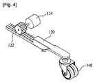
伸縮駆動部は、図4に示すように、ラック122と伸縮調節モータ124とを備えている。 As shown in FIG. 4, the extension / contraction drive unit includes a
ラック122は、延長足部120からベースフレーム110の方へ伸びており、その一面に歯が平面上に形成されている。 The
伸縮調節モータ124は、ベースフレーム110に設けられ、ラック122の歯に噛み合って正方向および逆方向に回転することにより、ラック122およびラック122が形成された延長足部120をラック122が形成された長手方向に移動させる。 The expansion /
すなわち、伸縮調節モータ124が正方向に回転すれば、ラック122および延長足部120がベースフレーム110の外側に押され、伸縮調節モータ124が逆方向に回転すれば、ラック122および延長足部120がベースフレーム110の内側に引かれる。 That is, if the expansion /
なお、延長足部120は、図5に示すように、ベースフレーム110に向かって延びたピストン123と、ピストン123を取り囲むように形成されたシリンダー125と、シリンダー125内の空気圧を調節するエアポンプ127とを備えた構成とすることもできる。 As shown in FIG. 5, the
すなわち、エアポンプ127によりシリンダー125内の空気圧を増加させると、ピストン123が押されながら延長足部120が伸張し、エアポンプ127によりシリンダー125内の空気圧を減少させると、ピストン123がシリンダー125内に収縮しながら延長足部120がベースフレーム110内に引かれて縮小される。 That is, when the air pressure in the
したがって、ベッド部170が回転して重心が変わると、図6に示すように、転覆防止制御部は、ベースフレーム110に設けられた延長足部120のうち、ベッド部170の重心が移動する側の延長足部120の伸縮調節モータ124またはエアポンプ127を駆動して延長足部120が伸張するように制御する。このとき、重心が移動しない側の延長足部120は小さくなるように制御して、ベースフレーム110全体が占める空間を相対的に小さくする。 Therefore, when the
このようにベッド部170の回転に伴って延長足部120を伸縮するので、ベッド部170およびポスト150を支持する支点がより広くなり、ベッド部170およびポスト150をより安定して支持することができる。 As described above, since the
転覆防止制御部は、高さ調節部によりベッド部170の回転に伴ってベッド部170の高さを調節する。 The rollover prevention control unit adjusts the height of the
図7は高さ調節部を示す断面図である。高さ調節部は、ポスト150に対してブーム160を昇降させるものであり、ねじ孔152と、スクリュー162と、高さ調節モータ164とを備えている。 FIG. 7 is a cross-sectional view showing the height adjusting portion. The height adjustment unit moves the
すなわち、ポスト150内にはポスト150の長手方向にそって内周面にねじ山が形成されたねじ孔152が設けられており、ブーム160にはねじ孔152の長手方向にそって外周面にねじ山が形成されたスクリュー162およびスクリュー162を正方向または逆方向に回転させる高さ調節モータ164を備えている。スクリュー162は、ねじ孔152の内周面に螺合し、高さ調節モータ164によって正方向または逆方向に回転してねじ孔152にそって上昇または下降させ、これによりブーム160も上昇または下降する。また、ブーム160に結合したベッド部170も上昇または下降する。 That is, a
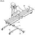
このように、ベッド部170が回転して重心が変わると、図8および図9に示すように、転覆防止制御部は高さ調節モータ164を回転させてベッド部170の高さを調節する。 Thus, when the
すなわち、ベッド部170が回転して重心位置が変わると、ベッド部170の高さを低くしてベッド部170の重心位置とベースフレーム110との距離を短くすることにより、作用するモーメントを小さくして移動用リフト装置100が転覆することを防止する。 That is, when the
以上、本発明を好ましい実施形態を用いて説明したが、本発明の技術的範囲は上記実施形態に記載の範囲には限定されない。上記実施形態に多様な変更を加えることが可能であることは本発明が属する分野の通常の知識を有する者にとっては明らかであり、このような変更を加えた形態も本発明の技術的範囲に含まれ得ることが請求範囲の記載から明らかである。 As mentioned above, although this invention was demonstrated using preferable embodiment, the technical scope of this invention is not limited to the range as described in the said embodiment. It is apparent to those skilled in the art to which the present invention belongs that various modifications can be made to the above-described embodiment, and such modified forms are also within the technical scope of the present invention. It is apparent from the description of the claims that it can be included.
Claims (7)
Translated fromJapanese前記ベースフレームから上方に所定長さ延びたポスト、およびこのポストによって支持され、使用者が横たわれるように水平に設けられたベッド部からなり、このベッド部は前記ベースフレームに対して回転および昇降可能に設けられた上部構造物と、
前記ベッド部の回転に伴ってベースフレームに対する前記ベッド部の高さを調節する転覆防止制御部と、
を含む転覆防止システムを備える移動用リフト装置。A base frame constituting the bottom surface;
A post that extends upward from the base frame by a predetermined length, and a bed portion that is supported by the post and that is horizontally provided so that a user lies down. The bed portion rotates and rotates with respect to the base frame. An upper structure provided so as to be movable up and down;
A rollover prevention control unit that adjusts the height of the bed unit relative to a base frame as the bed unit rotates;
A lift device for movement comprising a rollover prevention system including:
前記ベースフレームに対して回転可能に設けたポストと、
前記ポストにそって昇降可能に設けたブームと、
前記ブームに固定されたベッド部と、
を含むことを特徴とする請求項1記載の転覆防止システムを備える移動用リフト装置。The superstructure is
A post provided rotatably with respect to the base frame;
A boom that can be moved up and down along the post;
A bed portion fixed to the boom;
The lift apparatus for movement provided with the rollover prevention system of Claim 1 characterized by the above-mentioned.
前記ベッド部の回転角度によって前記ベースフレームに対するブームの高さを調節することを特徴とする請求項2記載の転覆防止システムを備えた移動用リフト装置。The rollover prevention control unit includes a height adjustment unit that raises and lowers the boom with respect to the post,
The lift apparatus for movement having the rollover prevention system according to claim 2, wherein the height of the boom relative to the base frame is adjusted according to the rotation angle of the bed portion.
前記ブーム内に前記ねじ孔の長手方向にそって設けられ、前記ねじ孔のねじ山に螺合して回転により昇降するように外周面にねじ山が形成されたスクリューと、
前記転覆防止制御部の制御によって前記スクリューを正方向または逆方向に回転させることにより前記ポストに螺合したブームを昇降させる高さ調節モータと、
を含むことを特徴とする請求項3記載の転覆防止システムを備える移動用リフト装置。The height adjusting portion is provided with a screw hole in which a thread is formed on an inner peripheral surface of the post along the longitudinal direction of the post,
A screw provided along the longitudinal direction of the screw hole in the boom, and having a screw thread formed on the outer peripheral surface thereof so as to be screwed into the screw thread of the screw hole and moved up and down by rotation;
A height adjustment motor that raises and lowers the boom screwed to the post by rotating the screw in the forward direction or the reverse direction under the control of the rollover prevention control unit;
The lift apparatus for movement provided with the rollover prevention system of Claim 3 characterized by the above-mentioned.
前記転覆防止制御部は、前記ベッド部の回転に伴って前記延長足部の伸縮量を調節することを特徴とする請求項1記載の転覆防止システムを備えた移動用リフト装置。At least one extension foot that selectively expands and contracts outside the base frame and supports the base frame movably with respect to a bottom surface;
2. The lift apparatus for movement with the rollover prevention system according to claim 1, wherein the rollover prevention control unit adjusts an amount of expansion and contraction of the extension foot part as the bed part rotates.
前記ベッド部の回転角度に応じて前記延長足部の伸縮量を調節することを特徴とする請求項5記載の転覆防止システムを備えた移動用リフト装置。The rollover prevention control unit has an expansion / contraction drive unit that expands and contracts the extension foot part with respect to the base
The lift apparatus for movement provided with the rollover prevention system according to claim 5, wherein an amount of expansion and contraction of the extension foot is adjusted according to a rotation angle of the bed.
前記延長足部から前記ベースフレーム側に延在し、一面に歯が形成されたラックと、
前記ベースフレームに固定され、前記ラックに噛み合って前記転覆防止制御部の制御によって正方向または逆方向に所定回数回転して前記ラックを直線方向に移動させる伸縮調節モータと、
を含むことを特徴とする請求項6記載の転覆防止システムを備えた移動用リフト装置。The telescopic drive unit is
A rack extending from the extended foot to the base frame side and having teeth formed on one surface;
A telescopic adjustment motor fixed to the base frame, meshed with the rack, and rotated a predetermined number of times in the forward or reverse direction by the control of the rollover prevention control unit to move the rack in a linear direction;
The lift apparatus for movement provided with the rollover prevention system of Claim 6 characterized by the above-mentioned.
Applications Claiming Priority (3)
| Application Number | Priority Date | Filing Date | Title |
|---|---|---|---|
| KR1020100029966AKR101156170B1 (en) | 2010-04-01 | 2010-04-01 | Movable Lift Device Having Anti-Turnover System |
| KR10-2010-0029966 | 2010-04-01 | ||
| PCT/KR2011/002263WO2011122896A2 (en) | 2010-04-01 | 2011-04-01 | Mobile lifting apparatus equipped with a rollover protection system |
Publications (2)
| Publication Number | Publication Date |
|---|---|
| JP2013523252A JP2013523252A (en) | 2013-06-17 |
| JP5406412B2true JP5406412B2 (en) | 2014-02-05 |
Family
ID=44712788
Family Applications (1)
| Application Number | Title | Priority Date | Filing Date |
|---|---|---|---|
| JP2013502488AActiveJP5406412B2 (en) | 2010-04-01 | 2011-04-01 | Moving lift device with anti-overturn system |
Country Status (4)
| Country | Link |
|---|---|
| US (1) | US20130007957A1 (en) |
| JP (1) | JP5406412B2 (en) |
| KR (1) | KR101156170B1 (en) |
| WO (1) | WO2011122896A2 (en) |
Families Citing this family (6)
| Publication number | Priority date | Publication date | Assignee | Title |
|---|---|---|---|---|
| KR101008944B1 (en)* | 2010-03-29 | 2011-01-17 | 한국생산기술연구원 | Lifting device with ring operation |
| US11839577B2 (en)* | 2012-12-20 | 2023-12-12 | Pano Solutions Pty. Ltd. | Mobile lifting system for disabled person |
| AU2013365664B2 (en)* | 2012-12-20 | 2018-11-08 | Pano Solutions Pty. Ltd. | Lifting device for disabled person |
| JP6510786B2 (en)* | 2014-09-26 | 2019-05-08 | オージー技研株式会社 | Carrier and bathing apparatus using the same |
| SI3351230T1 (en)* | 2016-07-07 | 2020-07-31 | BORGES BELZA, Manuel Jacinto | Stretcher for persons with reduced mobility |
| CN110302023A (en)* | 2019-06-28 | 2019-10-08 | 宁波康麦隆医疗器械有限公司 | A kind of moving vehicle lifting column and medical moving vehicle with safe release function |
Family Cites Families (10)
| Publication number | Priority date | Publication date | Assignee | Title |
|---|---|---|---|---|
| US4432359A (en)* | 1981-05-16 | 1984-02-21 | James Industries Limited | Equipment for handling invalids and the disabled |
| US4574410A (en) | 1983-06-23 | 1986-03-11 | Establissements Jouk | Device for handling people |
| JPH02167166A (en)* | 1988-12-21 | 1990-06-27 | Kubota Ltd | Nursing care equipment |
| US5201377A (en)* | 1990-02-23 | 1993-04-13 | Love Lift, L.P. | Wheelchair with sidewardly swingable seat |
| FI94834C (en)* | 1992-05-05 | 1995-11-10 | Ahlstroem Consumer Prod | Hospital Bed |
| US5740884A (en) | 1993-08-09 | 1998-04-21 | Dimucci; Vito A. | Power lifting unit and method for converting mobile patient transporter |
| JPH08224278A (en)* | 1995-02-22 | 1996-09-03 | Aprica Kassai Inc | Sickly person lift device |
| JPH09122179A (en)* | 1995-11-01 | 1997-05-13 | Shinko Giken:Kk | Helping machine |
| KR19990024131A (en)* | 1998-12-07 | 1999-03-25 | 황춘택 | Patient transfer device |
| US8155918B2 (en)* | 2007-12-31 | 2012-04-10 | Rauch & Romanshek Industries, Llc | Ambulance cot system |
- 2010
- 2010-04-01KRKR1020100029966Apatent/KR101156170B1/enactiveActive
- 2011
- 2011-04-01USUS13/636,689patent/US20130007957A1/ennot_activeAbandoned
- 2011-04-01JPJP2013502488Apatent/JP5406412B2/enactiveActive
- 2011-04-01WOPCT/KR2011/002263patent/WO2011122896A2/enactiveApplication Filing
Also Published As
| Publication number | Publication date |
|---|---|
| KR20110110571A (en) | 2011-10-07 |
| US20130007957A1 (en) | 2013-01-10 |
| KR101156170B1 (en) | 2012-06-18 |
| JP2013523252A (en) | 2013-06-17 |
| WO2011122896A2 (en) | 2011-10-06 |
| WO2011122896A3 (en) | 2012-01-26 |
Similar Documents
| Publication | Publication Date | Title |
|---|---|---|
| JP5406412B2 (en) | Moving lift device with anti-overturn system | |
| JP6683914B2 (en) | Foldable multi-function medical bed | |
| US6912746B2 (en) | Bed | |
| JP7207635B2 (en) | Rolling over support device | |
| CN208287175U (en) | Multi-functional electric medical bed | |
| JP2005517614A (en) | Lifting mechanism and medical equipment incorporating the lifting mechanism | |
| TW201801703A (en) | Stretcher for people with reduced mobility | |
| CN106726229A (en) | A kind of multifunctional medical nursing bed | |
| CN108814847A (en) | A kind of convenient type nursing bed | |
| CN111249084A (en) | Multifunctional electric sickbed | |
| CN204600956U (en) | Multi-direction flip type nursing bed | |
| US20190070054A1 (en) | Subject transfer apparatus | |
| US20130174339A1 (en) | Patient lift | |
| JP2019507611A (en) | Bed with movable frame | |
| CN212575128U (en) | quilt device | |
| CN209361149U (en) | A dermatological bed rest bedding support frame | |
| KR102819114B1 (en) | Medical bed capable of tilting left and right | |
| CN114099171A (en) | Sickbed capable of being used for bathing patients | |
| JP2006255090A (en) | Medical table for X-ray photography | |
| CN115363873A (en) | Device for assisting patients to get out of bed | |
| CN108670632A (en) | A kind of large area skin wounds bedridden patient bedding support device | |
| JPH0370560A (en) | Mechanism for supporting floor of bed | |
| CN108992254B (en) | Internal medicine clinical operation shallow | |
| CN208003189U (en) | Multifunctional bone surgical postoperative care stand | |
| JP2017217188A (en) | Mobile carriage for nursing care |
Legal Events
| Date | Code | Title | Description |
|---|---|---|---|
| TRDD | Decision of grant or rejection written | ||
| A01 | Written decision to grant a patent or to grant a registration (utility model) | Free format text:JAPANESE INTERMEDIATE CODE: A01 Effective date:20131022 | |
| A61 | First payment of annual fees (during grant procedure) | Free format text:JAPANESE INTERMEDIATE CODE: A61 Effective date:20131031 | |
| R150 | Certificate of patent or registration of utility model | Ref document number:5406412 Country of ref document:JP Free format text:JAPANESE INTERMEDIATE CODE: R150 | |
| R250 | Receipt of annual fees | Free format text:JAPANESE INTERMEDIATE CODE: R250 | |
| R250 | Receipt of annual fees | Free format text:JAPANESE INTERMEDIATE CODE: R250 | |
| R250 | Receipt of annual fees | Free format text:JAPANESE INTERMEDIATE CODE: R250 | |
| R250 | Receipt of annual fees | Free format text:JAPANESE INTERMEDIATE CODE: R250 | |
| R250 | Receipt of annual fees | Free format text:JAPANESE INTERMEDIATE CODE: R250 | |
| R250 | Receipt of annual fees | Free format text:JAPANESE INTERMEDIATE CODE: R250 | |
| R250 | Receipt of annual fees | Free format text:JAPANESE INTERMEDIATE CODE: R250 | |
| R250 | Receipt of annual fees | Free format text:JAPANESE INTERMEDIATE CODE: R250 | |
| R250 | Receipt of annual fees | Free format text:JAPANESE INTERMEDIATE CODE: R250 |