JP5404849B2 - Medical ultrasonic instrument having articulated jaws - Google Patents
Medical ultrasonic instrument having articulated jawsDownload PDFInfo
- Publication number
- JP5404849B2 JP5404849B2JP2012112420AJP2012112420AJP5404849B2JP 5404849 B2JP5404849 B2JP 5404849B2JP 2012112420 AJP2012112420 AJP 2012112420AJP 2012112420 AJP2012112420 AJP 2012112420AJP 5404849 B2JP5404849 B2JP 5404849B2
- Authority
- JP
- Japan
- Prior art keywords
- assembly
- end effector
- pair
- forceps
- jaw members
- Prior art date
- Legal status (The legal status is an assumption and is not a legal conclusion. Google has not performed a legal analysis and makes no representation as to the accuracy of the status listed.)
- Expired - Fee Related
Links
- 239000012636effectorSubstances0.000claimsdescription80
- 238000009210therapy by ultrasoundMethods0.000claimsdescription18
- 230000004044responseEffects0.000claimsdescription11
- 238000002604ultrasonographyMethods0.000description4
- 239000000463materialSubstances0.000description3
- 241001631457CannulaSpecies0.000description2
- 230000000712assemblyEffects0.000description2
- 238000000429assemblyMethods0.000description2
- 238000010586diagramMethods0.000description2
- 238000000034methodMethods0.000description2
- 229910000838Al alloyInorganic materials0.000description1
- 208000019901Anxiety diseaseDiseases0.000description1
- 229910001369BrassInorganic materials0.000description1
- 230000004913activationEffects0.000description1
- XAGFODPZIPBFFR-UHFFFAOYSA-NaluminiumChemical compound[Al]XAGFODPZIPBFFR-UHFFFAOYSA-N0.000description1
- 229910052782aluminiumInorganic materials0.000description1
- 230000036506anxietyEffects0.000description1
- 230000008901benefitEffects0.000description1
- DMFGNRRURHSENX-UHFFFAOYSA-Nberyllium copperChemical compound[Be].[Cu]DMFGNRRURHSENX-UHFFFAOYSA-N0.000description1
- 210000004204blood vesselAnatomy0.000description1
- 239000010951brassSubstances0.000description1
- 239000003990capacitorSubstances0.000description1
- 238000010276constructionMethods0.000description1
- 238000007599dischargingMethods0.000description1
- 238000005516engineering processMethods0.000description1
- 230000009975flexible effectEffects0.000description1
- 230000035876healingEffects0.000description1
- 230000023597hemostasisEffects0.000description1
- 230000003993interactionEffects0.000description1
- 230000013011matingEffects0.000description1
- 238000002324minimally invasive surgeryMethods0.000description1
- 238000012986modificationMethods0.000description1
- 230000004048modificationEffects0.000description1
- 238000002355open surgical procedureMethods0.000description1
- 210000000056organAnatomy0.000description1
- 238000007789sealingMethods0.000description1
- 229910001220stainless steelInorganic materials0.000description1
- 239000010935stainless steelSubstances0.000description1
- 229910001256stainless steel alloyInorganic materials0.000description1
- 238000001356surgical procedureMethods0.000description1
- 230000002792vascularEffects0.000description1
Images


Classifications
- A—HUMAN NECESSITIES
- A61—MEDICAL OR VETERINARY SCIENCE; HYGIENE
- A61B—DIAGNOSIS; SURGERY; IDENTIFICATION
- A61B18/00—Surgical instruments, devices or methods for transferring non-mechanical forms of energy to or from the body
- A—HUMAN NECESSITIES
- A61—MEDICAL OR VETERINARY SCIENCE; HYGIENE
- A61B—DIAGNOSIS; SURGERY; IDENTIFICATION
- A61B17/00—Surgical instruments, devices or methods
- A61B17/32—Surgical cutting instruments
- A61B17/320068—Surgical cutting instruments using mechanical vibrations, e.g. ultrasonic
- A61B17/320092—Surgical cutting instruments using mechanical vibrations, e.g. ultrasonic with additional movable means for clamping or cutting tissue, e.g. with a pivoting jaw
- A—HUMAN NECESSITIES
- A61—MEDICAL OR VETERINARY SCIENCE; HYGIENE
- A61B—DIAGNOSIS; SURGERY; IDENTIFICATION
- A61B17/00—Surgical instruments, devices or methods
- A61B2017/00681—Aspects not otherwise provided for
- A61B2017/00734—Aspects not otherwise provided for battery operated
- A—HUMAN NECESSITIES
- A61—MEDICAL OR VETERINARY SCIENCE; HYGIENE
- A61B—DIAGNOSIS; SURGERY; IDENTIFICATION
- A61B17/00—Surgical instruments, devices or methods
- A61B17/28—Surgical forceps
- A61B17/29—Forceps for use in minimally invasive surgery
- A61B2017/2926—Details of heads or jaws
- A61B2017/2927—Details of heads or jaws the angular position of the head being adjustable with respect to the shaft
- A61B2017/2929—Details of heads or jaws the angular position of the head being adjustable with respect to the shaft with a head rotatable about the longitudinal axis of the shaft
- A—HUMAN NECESSITIES
- A61—MEDICAL OR VETERINARY SCIENCE; HYGIENE
- A61B—DIAGNOSIS; SURGERY; IDENTIFICATION
- A61B17/00—Surgical instruments, devices or methods
- A61B17/28—Surgical forceps
- A61B17/29—Forceps for use in minimally invasive surgery
- A61B2017/2926—Details of heads or jaws
- A61B2017/2932—Transmission of forces to jaw members
- A61B2017/2933—Transmission of forces to jaw members camming or guiding means
- A—HUMAN NECESSITIES
- A61—MEDICAL OR VETERINARY SCIENCE; HYGIENE
- A61B—DIAGNOSIS; SURGERY; IDENTIFICATION
- A61B17/00—Surgical instruments, devices or methods
- A61B17/28—Surgical forceps
- A61B17/29—Forceps for use in minimally invasive surgery
- A61B2017/2926—Details of heads or jaws
- A61B2017/2932—Transmission of forces to jaw members
- A61B2017/2939—Details of linkages or pivot points
- A—HUMAN NECESSITIES
- A61—MEDICAL OR VETERINARY SCIENCE; HYGIENE
- A61B—DIAGNOSIS; SURGERY; IDENTIFICATION
- A61B17/00—Surgical instruments, devices or methods
- A61B17/28—Surgical forceps
- A61B17/29—Forceps for use in minimally invasive surgery
- A61B2017/2947—Pivots
- A—HUMAN NECESSITIES
- A61—MEDICAL OR VETERINARY SCIENCE; HYGIENE
- A61B—DIAGNOSIS; SURGERY; IDENTIFICATION
- A61B17/00—Surgical instruments, devices or methods
- A61B17/32—Surgical cutting instruments
- A61B17/320068—Surgical cutting instruments using mechanical vibrations, e.g. ultrasonic
- A61B17/320092—Surgical cutting instruments using mechanical vibrations, e.g. ultrasonic with additional movable means for clamping or cutting tissue, e.g. with a pivoting jaw
- A61B2017/320093—Surgical cutting instruments using mechanical vibrations, e.g. ultrasonic with additional movable means for clamping or cutting tissue, e.g. with a pivoting jaw additional movable means performing cutting operation
- A—HUMAN NECESSITIES
- A61—MEDICAL OR VETERINARY SCIENCE; HYGIENE
- A61B—DIAGNOSIS; SURGERY; IDENTIFICATION
- A61B17/00—Surgical instruments, devices or methods
- A61B17/32—Surgical cutting instruments
- A61B17/320068—Surgical cutting instruments using mechanical vibrations, e.g. ultrasonic
- A61B17/320092—Surgical cutting instruments using mechanical vibrations, e.g. ultrasonic with additional movable means for clamping or cutting tissue, e.g. with a pivoting jaw
- A61B2017/320094—Surgical cutting instruments using mechanical vibrations, e.g. ultrasonic with additional movable means for clamping or cutting tissue, e.g. with a pivoting jaw additional movable means performing clamping operation
- A—HUMAN NECESSITIES
- A61—MEDICAL OR VETERINARY SCIENCE; HYGIENE
- A61B—DIAGNOSIS; SURGERY; IDENTIFICATION
- A61B17/00—Surgical instruments, devices or methods
- A61B17/32—Surgical cutting instruments
- A61B17/320068—Surgical cutting instruments using mechanical vibrations, e.g. ultrasonic
- A61B17/320092—Surgical cutting instruments using mechanical vibrations, e.g. ultrasonic with additional movable means for clamping or cutting tissue, e.g. with a pivoting jaw
- A61B2017/320095—Surgical cutting instruments using mechanical vibrations, e.g. ultrasonic with additional movable means for clamping or cutting tissue, e.g. with a pivoting jaw with sealing or cauterizing means
Landscapes
- Health & Medical Sciences (AREA)
- Surgery (AREA)
- Life Sciences & Earth Sciences (AREA)
- Engineering & Computer Science (AREA)
- Heart & Thoracic Surgery (AREA)
- Nuclear Medicine, Radiotherapy & Molecular Imaging (AREA)
- Biomedical Technology (AREA)
- Medical Informatics (AREA)
- Molecular Biology (AREA)
- Animal Behavior & Ethology (AREA)
- General Health & Medical Sciences (AREA)
- Public Health (AREA)
- Veterinary Medicine (AREA)
- Otolaryngology (AREA)
- Mechanical Engineering (AREA)
- Dentistry (AREA)
- Surgical Instruments (AREA)
Description
Translated fromJapanese (発明の詳細な説明)
(背景)
(1.技術分野)
本開示は、内視鏡外科手術器具に関する。より具体的には、本開示は、組織を密閉及び切断するために超音波を使用する内視鏡鉗子に関する。(Detailed description of the invention)
(background)
(1. Technical field)
The present disclosure relates to endoscopic surgical instruments. More specifically, the present disclosure relates to endoscopic forceps that use ultrasound to seal and cut tissue.
(2.関連技術の背景)
開放外科手術処置における使用のための開放器具に代わるものとして、多くの現代の外科医は、より小さい、穿刺様の切開を通して、遠隔で器官にアクセスする内視鏡および内視鏡電気外科装置(例えば、内視鏡または腹腔鏡鉗子)を用いる。これらの器具は、低侵襲処置(例えば、不安が少なく、痛みが少なく、治癒時間が減少されるという利益を患者が受ける傾向がある内視鏡または腹腔鏡処置)における使用に特に適している。一般的には、内視鏡鉗子は、トロカールによって作成された1つ以上のさまざまなタイプのカニューレまたはアクセスポート(一般的には、約5ミリメートルから約15ミリメートルの範囲の開口部を有している)を通して、患者に挿入される。認識され得るように、より小さいカニューレが通常は好ましい。(2. Background of related technology)
As an alternative to open instruments for use in open surgical procedures, many modern surgeons have endoscopic and endoscopic electrosurgical devices that access organs remotely through smaller, puncture-like incisions (eg, , Endoscope or laparoscopic forceps). These instruments are particularly suitable for use in minimally invasive procedures (eg, endoscopic or laparoscopic procedures where patients tend to benefit from less anxiety, less pain, and reduced healing time). Typically, endoscopic forceps have one or more various types of cannulas or access ports created by trocars (typically having openings in the range of about 5 millimeters to about 15 millimeters). Inserted into the patient. As can be appreciated, smaller cannulas are usually preferred.
いくつかの内視鏡器具は、ある医療処置を実施するために、超音波振動を使用し得る。特に、超音波器具は、組織を治療するために、超音波周波数で伝達された力学的振動エネルギーを使用する。適切なエネルギーレベルで伝達される場合、超音波振動は、組織を凝固、焼灼、溶解、密閉、切断、乾燥および/または高周波治療するために用いられ得、止血をもたらす。 Some endoscopic instruments may use ultrasonic vibrations to perform certain medical procedures. In particular, ultrasonic instruments use mechanical vibration energy transmitted at ultrasonic frequencies to treat tissue. When transmitted at an appropriate energy level, ultrasonic vibration can be used to coagulate, cauterize, dissolve, seal, cut, dry and / or radiofrequency treat tissue, resulting in hemostasis.
超音波を使用し、小さいカニューレ(例えば、5ミリメートル未満のカニューレ)との使用に対して構成されている内視鏡鉗子は、内視鏡器具の製造業者に対して設計の難問を提示し得る。 Endoscopic forceps that use ultrasound and are configured for use with a small cannula (e.g., a cannula less than 5 millimeters) can present design challenges to the endoscopic instrument manufacturer. .
(概要)
そのため、本開示は、ハウジング、シャフトアセンブリ、エンドエフェクタアセンブリ、トリガーアセンブリ、回転アセンブリ、関節運動器および導波管アセンブリを含む鉗子に関する。ハウジングは、1つ以上の変換器を有している。1つ以上の変換器は、エネルギー供給源から1つ以上の変換器に伝達されたエネルギーに応答して、力学的振動を生成するように構成されている。力学的振動は、超音波周波数を有し得る。鉗子は、エネルギー供給源として作用するバッテリーを含み得る。バッテリーは、スマートバッテリーであり得る。(Overview)
As such, the present disclosure relates to forceps including a housing, a shaft assembly, an end effector assembly, a trigger assembly, a rotation assembly, an articulator, and a waveguide assembly. The housing has one or more transducers. The one or more transducers are configured to generate mechanical vibrations in response to energy transferred from the energy source to the one or more transducers. The mechanical vibration can have an ultrasonic frequency. The forceps may include a battery that acts as an energy source. The battery can be a smart battery.
シャフトアセンブリは、ハウジングから延在し、1つ以上の関節運動部材および1つ以上のクランプ締め部材を含む。長手方向軸は、シャフトアセンブリを通して規定される。エンドエフェクタアセンブリは、シャフトアセンブリの遠位端部に配置され、1つ以上のクランプ締め部材の移動に応答して、接近された構成と接近されていない構成との間を旋回可能な1対の対向するジョー部材を含む。1対のジョー部材のうちの1つまたは両方は、1対の対向するジョー部材が接近された構成と接近されていない構成との間を旋回可能であるように、クランプ締め部材の移動が係合部材を旋回させるようにクランプ締め部材に動作するように関連付けられている係合部材を含む。1対の対向するジョー部材は、シャフトアセンブリに対して、シャフトアセンブリの長手方向軸を横断する軸の周りに関節運動する。1対のジョー部材のうちの1つまたは両方は、1対のジョー部材を通るチャネルを規定する。 The shaft assembly extends from the housing and includes one or more articulation members and one or more clamping members. A longitudinal axis is defined through the shaft assembly. An end effector assembly is disposed at the distal end of the shaft assembly and is capable of pivoting between an approached configuration and an unaccessed configuration in response to movement of one or more clamping members. Opposing jaw members. One or both of the pair of jaw members is responsible for the movement of the clamping member so that the pair of opposing jaw members can pivot between an approached configuration and an unclosed configuration. An engagement member is operatively associated with the clamping member to pivot the mating member. A pair of opposing jaw members articulate relative to the shaft assembly about an axis that intersects the longitudinal axis of the shaft assembly. One or both of the pair of jaw members define a channel through the pair of jaw members.
1つ以上の関節運動部材は、1対の対向するジョー部材をシャフトアセンブリの長手方向軸に対して関節運動させるように構成されている。各関節運動部材は、1対のジョー部材を移動させるために長手方向に並進可能である。いくつかの実施形態において、第一の関節運動部材は、1対のジョーを横方向に関節運動させるために、第二の関節運動部材とは反対の方向に移動する。各関節運動部材は、1対のジョー部材が関節運動する際に、1つ以上の関節運動部材が1つ以上のボールベアリングの外面に沿って移動するように、1対のジョー部材のうちの1つまたは両方に動作可能に結合された1つ以上のボールベアリングによって、1対のジョー部材のうちの1つまたは両方に動作可能に結合される。いくつかの実施形態において、2つ以上の関節運動部材は、エンドエフェクタアセンブリが導波管アセンブリに対して長手方向に並進するように、同じ長手方向に同時に移動する。 The one or more articulation members are configured to articulate a pair of opposing jaw members relative to the longitudinal axis of the shaft assembly. Each articulation member is translatable longitudinally to move a pair of jaw members. In some embodiments, the first articulation member moves in the opposite direction to the second articulation member to articulate the pair of jaws laterally. Each articulation member includes a pair of jaw members such that when the pair of jaw members articulates, the one or more articulation members move along the outer surface of the one or more ball bearings. One or more ball bearings operably coupled to one or both are operably coupled to one or both of the pair of jaw members. In some embodiments, the two or more articulation members move simultaneously in the same longitudinal direction such that the end effector assembly translates longitudinally relative to the waveguide assembly.
導波管アセンブリは、シャフトアセンブリ内に位置決めされ、変換器によって生成された力学的振動を受け取るように構成されている。導波管アセンブリは、少なくとも部分的に、対向するジョー部材のうちの1つ以上の中に位置決め可能である。導波管アセンブリは、導波管および超音波治療部材を含む。超音波治療部材は、力学的振動を1つ以上の変換器から受け取ることと、1対の対向するジョー部材の間に位置決めされた組織を治療するために、力学的振動を伝達することとを行うように構成されている。超音波治療部材の少なくとも一部は、1対のジョー部材のうちの1つまたは両方によって規定されたチャネル内に位置決め可能である。超音波治療部材がチャネル内に位置決めされた場合、エンドエフェクタアセンブリは、関節運動させることを妨げられる。導波管アセンブリは、エンドエフェクタアセンブリに対して長手方向に並進可能であり得る。 The waveguide assembly is positioned within the shaft assembly and is configured to receive mechanical vibrations generated by the transducer. The waveguide assembly is positionable, at least in part, in one or more of the opposing jaw members. The waveguide assembly includes a waveguide and an ultrasound treatment member. The ultrasonic treatment member receives mechanical vibrations from one or more transducers and transmits the mechanical vibrations to treat tissue positioned between a pair of opposing jaw members. Configured to do. At least a portion of the ultrasound treatment member is positionable within a channel defined by one or both of the pair of jaw members. When the ultrasound treatment member is positioned within the channel, the end effector assembly is prevented from articulating. The waveguide assembly may be longitudinally translatable with respect to the end effector assembly.
トリガーアセンブリは、ハウジングに動作可能に結合される。トリガーアセンブリは、作動トリガーおよびクランプ締めトリガーを含む。作動トリガーは、作動トリガーの作動の際に、エネルギー供給源から1つ以上の変換器へのエネルギーの伝達を容易にするように構成されている。クランプ締めトリガーは、クランプ締めトリガーの作動の際に、1対の対向するジョー部材を接近されていない構成と接近された構成との間に移動させるために、1つ以上のクランプ締め部材を移動させるように構成されている。 The trigger assembly is operably coupled to the housing. The trigger assembly includes an actuation trigger and a clamping trigger. The actuation trigger is configured to facilitate the transfer of energy from the energy source to the one or more transducers upon actuation of the actuation trigger. A clamping trigger moves one or more clamping members to move a pair of opposing jaw members between an unclosed configuration and a closed configuration upon actuation of the clamping trigger It is configured to let you.
回転アセンブリは、シャフトアセンブリに動作可能に結合される。回転アセンブリは、回転アセンブリの作動の際に、シャフトアセンブリおよびエンドエフェクタアセンブリを回転させるように構成されている。 The rotating assembly is operably coupled to the shaft assembly. The rotating assembly is configured to rotate the shaft assembly and the end effector assembly upon operation of the rotating assembly.
関節運動器は、1つ以上の関節運動部材に動作可能に結合される。1つ以上の関節運動部材は、関節運動器の移動に応答して、移動する。 The articulator is operably coupled to one or more articulation members. The one or more articulation members move in response to movement of the articulator.
例えば、本発明は、以下を提供する。 For example, the present invention provides the following.
(項目1)
少なくとも1つの変換器を有しているハウジングであって、該少なくとも1つの変換器は、エネルギー供給源から該少なくとも1つの変換器に伝達されたエネルギーに応答して、力学的振動を生成するように構成されている、ハウジングと、
該ハウジングから延在するシャフトアセンブリであって、該シャフトアセンブリは、少なくとも1つの関節運動部材と、少なくとも1つのクランプ締め部材と、該シャフトアセンブリを通って規定される長手方向軸とを含む、シャフトアセンブリと、
該シャフトアセンブリの遠位端部に配置されたエンドエフェクタアセンブリであって、該エンドエフェクタアセンブリは、該少なくとも1つのクランプ締め部材の移動に応答して、接近された構成と接近されていない構成との間を旋回可能な1対の対向するジョー部材を含み、該少なくとも1つの関節運動部材は、該1対の対向するジョー部材を該シャフトアセンブリの長手方向軸に対して関節運動させるように構成されている、エンドエフェクタアセンブリと、
該シャフトアセンブリ内に位置決めされた導波管アセンブリであって、該導波管アセンブリは、該変換器によって生成された力学的振動を受け取るように構成されており、該エンドエフェクタアセンブリは、該シャフトおよび導波管アセンブリの周りの該エンドエフェクタアセンブリの関節運動を容易にするために、該導波管アセンブリに対して、該導波管アセンブリを越えて長手方向に並進可能である、導波管アセンブリと
を含む、鉗子。(Item 1)
A housing having at least one transducer, wherein the at least one transducer is responsive to energy transferred from an energy source to the at least one transducer to generate a mechanical vibration. A housing,
A shaft assembly extending from the housing, the shaft assembly including at least one articulation member, at least one clamping member, and a longitudinal axis defined through the shaft assembly. Assembly,
An end effector assembly disposed at a distal end of the shaft assembly, the end effector assembly being in an approached configuration and an inaccessible configuration in response to movement of the at least one clamping member; A pair of opposing jaw members pivotable between, wherein the at least one articulating member is configured to articulate the pair of opposing jaw members relative to a longitudinal axis of the shaft assembly An end effector assembly,
A waveguide assembly positioned within the shaft assembly, the waveguide assembly configured to receive mechanical vibrations generated by the transducer, the end effector assembly comprising: And a waveguide that is translatable longitudinally relative to the waveguide assembly to facilitate articulation of the end effector assembly about the waveguide assembly. An assembly and a forceps.
(項目2)
前記1対の対向するジョー部材は、前記シャフトアセンブリに対して、該シャフトアセンブリの長手方向軸を横断する軸の周りに関節運動する、上記項目に記載の鉗子。(Item 2)
The forceps as in any preceding item, wherein the pair of opposing jaw members articulate relative to the shaft assembly about an axis transverse to a longitudinal axis of the shaft assembly.
(項目3)
前記シャフトアセンブリは、少なくとも2つの関節運動部材を含み、各関節運動部材は、前記1対のジョー部材を移動させるために、長手方向に並進可能である、上記項目のうちのいずれか一項目に記載の鉗子。(Item 3)
The shaft assembly includes at least two articulation members, each articulation member being longitudinally translatable to move the pair of jaw members. The forceps described.
(項目4)
第一の関節運動部材は、前記1対のジョー部材を横方向に関節運動させるために、第二の関節運動部材とは反対の方向に移動する、上記項目のうちのいずれか一項目に記載の鉗子。(Item 4)
The first articulation member moves in a direction opposite to the second articulation member in order to articulate the pair of jaw members laterally. Forceps.
(項目5)
前記少なくとも2つの関節運動部材は、前記エンドエフェクタアセンブリが前記導波管アセンブリに対して、長手方向に並進するように、同じ長手方向に同時に移動する、上記項目のうちのいずれか一項目に記載の鉗子。(Item 5)
The at least two articulation members according to any one of the preceding items, wherein the end effector assembly moves simultaneously in the same longitudinal direction such that the end effector assembly translates longitudinally relative to the waveguide assembly. Forceps.
(項目6)
各関節運動部材は、少なくとも1つのボールベアリングによって前記1対の対向するジョー部材のうちの少なくとも1つに動作可能に結合され、該少なくとも1つのボールベアリングは、該1対のジョー部材が関節運動する際に、前記少なくとも1つの関節運動部材が該少なくとも1つのボールベアリングの外面に沿って移動するように、該1対の対向するジョー部材のうちの少なくとも1つに動作可能にされている、上記項目のうちのいずれか一項目に記載の鉗子。(Item 6)
Each articulation member is operably coupled to at least one of the pair of opposing jaw members by at least one ball bearing, wherein the at least one ball bearing is articulated by the pair of jaw members. And wherein at least one of the pair of opposing jaw members is operable so that the at least one articulation member moves along an outer surface of the at least one ball bearing. The forceps according to any one of the above items.
(項目7)
前記導波管アセンブリは、導波管および超音波治療部材を含み、該超音波治療部材は、前記少なくとも1つの変換器から前記力学的振動を受け取ることと、前記1対の対向するジョー部材の間に位置決めされた組織を治療するために、該力学的振動を伝達することとを行うように構成されている、上記項目のうちのいずれか一項目に記載の鉗子。(Item 7)
The waveguide assembly includes a waveguide and an ultrasound treatment member that receives the mechanical vibrations from the at least one transducer and the pair of opposing jaw members. The forceps according to any one of the preceding items, wherein the forceps are configured to transmit the mechanical vibration to treat tissue positioned therebetween.
(項目8)
前記1対の対向するジョー部材のうちの少なくとも1つは、係合部材を含み、該係合部材は、前記クランプ締め部材の移動が該係合部材を旋回させ、該1対の対向するジョー部材が前記接近された構成と接近されていない構成との間に位置決め可能であるように、該クランプ締め部材に動作するように関連付けられている、上記項目のうちのいずれか一項目に記載の鉗子。(Item 8)
At least one of the pair of opposing jaw members includes an engagement member, the engagement member pivoting the engagement member upon movement of the clamping member, the pair of opposing jaws An item according to any one of the preceding items, wherein the member is operatively associated with the clamping member such that a member is positionable between the approached configuration and the unclosed configuration. forceps.
(項目9)
前記力学的振動は、超音波周波数を有している、上記項目のうちのいずれか一項目に記載の鉗子。(Item 9)
The forceps according to any one of the preceding items, wherein the mechanical vibration has an ultrasonic frequency.
(項目10)
前記ハウジングに動作可能に結合されたトリガーアセンブリをさらに含み、該トリガーアセンブリは、作動トリガーおよびクランプ締めトリガーを含み、該作動トリガーは、該作動トリガーの作動の際に、前記エネルギー供給源から前記少なくとも1つの変換器へのエネルギーの伝達を容易にするように構成されており、該クランプ締めトリガーは、該クランプ締めトリガーの作動の際に、前記1対の対向するジョー部材を接近されていない構成と接近された構成との間に移動させるために、該少なくとも1つのクランプ締め部材を移動させるように構成されている、上記項目のうちのいずれか一項目に記載の鉗子。(Item 10)
A trigger assembly operably coupled to the housing, the trigger assembly including an actuation trigger and a clamping trigger, wherein the actuation trigger from the energy source upon actuation of the actuation trigger; Configured to facilitate the transfer of energy to a transducer, wherein the clamping trigger is not accessed by the pair of opposing jaw members upon actuation of the clamping trigger The forceps according to any one of the preceding items, wherein the forceps are configured to move the at least one clamping member for movement between and the approached configuration.
(項目1a)
少なくとも1つの変換器を有しているハウジングであって、該少なくとも1つの変換器は、エネルギー供給源から該少なくとも1つの変換器に伝達されるエネルギーに応答して、力学的振動を生成するように構成されている、ハウジングと、
該ハウジングから延在するシャフトアセンブリであって、該シャフトアセンブリは、少なくとも1つの関節運動部材と、少なくとも1つのクランプ締め部材と、該シャフトアセンブリを通って規定される長手方向軸とを含む、シャフトアセンブリと、
該シャフトアセンブリの遠位端部に配置されたエンドエフェクタアセンブリであって、該エンドエフェクタアセンブリは、該少なくとも1つのクランプ締め部材の移動に応答して、接近された構成と接近されていない構成との間を旋回可能な1対の対向するジョー部材を含み、該少なくとも1つの関節運動部材は、該1対の対向するジョー部材を該シャフトアセンブリの長手方向軸に対して関節運動させるように構成されている、エンドエフェクタアセンブリと、
該シャフトアセンブリ内に位置決めされた導波管アセンブリであって、該導波管アセンブリは、該変換器によって生成された力学的振動を受け取るように構成されており、該エンドエフェクタアセンブリは、該対向するジョー部材のうちの少なくとも1つ内に少なくとも部分的に位置決め可能である、導波管アセンブリと
を含む、鉗子。(Item 1a)
A housing having at least one transducer, wherein the at least one transducer is responsive to energy transmitted to the at least one transducer from an energy source to generate a mechanical vibration. A housing,
A shaft assembly extending from the housing, the shaft assembly including at least one articulation member, at least one clamping member, and a longitudinal axis defined through the shaft assembly. Assembly,
An end effector assembly disposed at a distal end of the shaft assembly, the end effector assembly being in an approached configuration and an inaccessible configuration in response to movement of the at least one clamping member; A pair of opposing jaw members pivotable between, wherein the at least one articulating member is configured to articulate the pair of opposing jaw members relative to a longitudinal axis of the shaft assembly An end effector assembly,
A waveguide assembly positioned within the shaft assembly, wherein the waveguide assembly is configured to receive mechanical vibrations generated by the transducer, and the end effector assembly is And a waveguide assembly that is at least partially positionable within at least one of the jaw members.
(項目2a)
前記1対の対向するジョー部材は、前記シャフトアセンブリに対して、該シャフトアセンブリの長手方向軸を横断する軸の周りに関節運動させる、上記項目に記載の鉗子。(Item 2a)
The forceps as described above, wherein the pair of opposing jaw members articulate relative to the shaft assembly about an axis transverse to a longitudinal axis of the shaft assembly.
(項目3a)
前記シャフトアセンブリは、少なくとも2つの関節運動部材を含み、各関節運動部材は、前記1対のジョー部材を移動させるために、長手方向に並進可能である、上記項目のうちのいずれか一項目に記載の鉗子。(Item 3a)
The shaft assembly includes at least two articulation members, each articulation member being longitudinally translatable to move the pair of jaw members. The forceps described.
(項目4a)
第一の関節運動部材は、前記1対のジョー部材を横方向に関節運動させるために、第二の関節運動部材とは反対の方向に移動する、上記項目のうちのいずれか一項目に記載の鉗子。(Item 4a)
The first articulation member moves in a direction opposite to the second articulation member in order to articulate the pair of jaw members laterally. Forceps.
(項目5a)
前記少なくとも2つの関節運動部材は、前記エンドエフェクタアセンブリが前記導波管アセンブリに対して、長手方向に並進するように、同じ長手方向に同時に移動する、上記項目のうちのいずれか一項目に記載の鉗子。(Item 5a)
The at least two articulation members according to any one of the preceding items, wherein the end effector assembly moves simultaneously in the same longitudinal direction such that the end effector assembly translates longitudinally relative to the waveguide assembly. Forceps.
(項目6a)
各関節運動部材は、少なくとも1つのボールベアリングによって前記1対の対向するジョー部材のうちの少なくとも1つに動作可能に結合され、該少なくとも1つのボールベアリングは、該1対のジョー部材が関節運動する際に、前記少なくとも1つの関節運動部材が該少なくとも1つのボールベアリングの外面に沿って移動するように、該1対の対向するジョー部材のうちの少なくとも1つに動作可能に結合されている、上記項目のうちのいずれか一項目に記載の鉗子。(Item 6a)
Each articulation member is operably coupled to at least one of the pair of opposing jaw members by at least one ball bearing, wherein the at least one ball bearing is articulated by the pair of jaw members. The at least one articulation member is operatively coupled to at least one of the pair of opposing jaw members such that the at least one articulation member moves along an outer surface of the at least one ball bearing. The forceps according to any one of the above items.
(項目7a)
前記導波管アセンブリは、前記エンドエフェクタアセンブリに対して、長手方向に並進可能である、上記項目のうちのいずれか一項目に記載の鉗子。(Item 7a)
The forceps according to any one of the preceding items, wherein the waveguide assembly is translatable longitudinally relative to the end effector assembly.
(項目8a)
前記導波管アセンブリは、導波管および超音波治療部材を含み、該超音波治療部材は、前記少なくとも1つの変換器から前記力学的振動を受け取ることと、前記1対の対向するジョー部材の間に位置決めされた組織を治療するために、該力学的振動を伝達することとを行うように構成されている、上記項目のうちのいずれか一項目に記載の鉗子。(Item 8a)
The waveguide assembly includes a waveguide and an ultrasound treatment member that receives the mechanical vibrations from the at least one transducer and the pair of opposing jaw members. The forceps according to any one of the preceding items, wherein the forceps are configured to transmit the mechanical vibration to treat tissue positioned therebetween.
(項目9a)
1対のジョー部材のうちの少なくとも1つは、該1対のジョー部材のうちの少なくとも1つを通るチャネルを規定し、前記超音波治療部材の少なくとも一部は、該チャネル内に位置決め可能である、上記項目のうちのいずれか一項目に記載の鉗子。(Item 9a)
At least one of the pair of jaw members defines a channel through at least one of the pair of jaw members, and at least a portion of the ultrasound treatment member is positionable within the channel. The forceps according to any one of the above items.
(項目10a)
前記超音波治療部材が、前記1対のジョー部材のうちの少なくとも1つによって規定されたチャネル内に位置決めされた場合、前記エンドエフェクタアセンブリは、関節運動させることを妨げられる、上記項目のうちのいずれか一項目に記載の鉗子。(Item 10a)
Of the preceding items, the end effector assembly is prevented from articulating when the ultrasound treatment member is positioned within a channel defined by at least one of the pair of jaw members. The forceps as described in any one item.
(項目11a)
前記1対のジョー部材のうちの少なくとも1つは、係合部材を含み、該係合部材は、前記クランプ締め部材の移動が該係合部材を旋回させ、該1対の対向するジョー部材が前記接近された構成と接近されていない構成との間に位置決め可能であるように、該クランプ締め部材に動作するように関連付けられている、上記項目のうちのいずれか一項目に記載の鉗子。(Item 11a)
At least one of the pair of jaw members includes an engagement member, wherein movement of the clamping member pivots the engagement member such that the pair of opposing jaw members The forceps according to any one of the preceding items, wherein the forceps is operatively associated with the clamping member so as to be positionable between the approached configuration and the non-accessed configuration.
(項目12a)
前記力学的振動は、超音波周波数を有している、上記項目のうちのいずれか一項目に記載の鉗子。(Item 12a)
The forceps according to any one of the preceding items, wherein the mechanical vibration has an ultrasonic frequency.
(項目13a)
前記鉗子は、前記エネルギー供給源として作用するバッテリーを含む、上記項目のうちのいずれか一項目に記載の鉗子。(Item 13a)
The forceps according to any one of the preceding items, wherein the forceps includes a battery that acts as the energy supply source.
(項目14a)
前記バッテリーは、スマートバッテリーである、上記項目のうちのいずれか一項目に記載の鉗子。(Item 14a)
The forceps according to any one of the above items, wherein the battery is a smart battery.
(項目15a)
前記ハウジングに動作可能に結合されたトリガーアセンブリをさらに含み、該トリガーアセンブリは、作動トリガーおよびクランプ締めトリガーを含み、該作動トリガーは、該作動トリガーの作動の際に、前記エネルギー供給源から前記少なくとも1つの変換器へのエネルギーの伝達を容易にするように構成されており、該クランプ締めトリガーは、該クランプ締めトリガーの作動の際に、前記1対の対向するジョー部材を接近されていない構成と接近された構成との間に移動させるために、該少なくとも1つのクランプ締め部材を移動させるように構成されている、上記項目のうちのいずれか一項目に記載の鉗子。(Item 15a)
A trigger assembly operably coupled to the housing, the trigger assembly including an actuation trigger and a clamping trigger, wherein the actuation trigger from the energy source upon actuation of the actuation trigger; Configured to facilitate the transfer of energy to a transducer, wherein the clamping trigger is not accessed by the pair of opposing jaw members upon actuation of the clamping trigger The forceps according to any one of the preceding items, wherein the forceps are configured to move the at least one clamping member for movement between and the approached configuration.
(項目16a)
前記シャフトアセンブリに動作可能に結合された回転アセンブリをさらに含み、該回転アセンブリは、該回転アセンブリの回転の際に、該シャフトアセンブリおよび前記エンドエフェクタアセンブリを回転させるように構成されている、上記項目のうちのいずれか一項目に記載の鉗子。(Item 16a)
The item further comprising a rotating assembly operably coupled to the shaft assembly, wherein the rotating assembly is configured to rotate the shaft assembly and the end effector assembly upon rotation of the rotating assembly. The forceps as described in any one of these items.
(項目17a)
前記少なくとも1つの関節運動部材に動作可能に結合された関節運動器をさらに含み、該少なくとも1つの関節運動部材は、関節運動器の移動に応答して、移動する、上記項目のうちのいずれか一項目に記載の鉗子。(Item 17a)
Any of the preceding items further comprising an articulator operably coupled to the at least one articulation member, the at least one articulation member moving in response to movement of the articulator. Forceps according to one item.
(摘要)
鉗子は、ハウジング、シャフトアセンブリ、エンドエフェクタアセンブリおよび導波管アセンブリを含む。ハウジングは、エネルギー供給源から1つ以上の変換器に伝達されたエネルギーに応答して、力学的振動を生成する1つ以上の変換器を有している。シャフトアセンブリは、ハウジングから延在し、1つ以上の関節運動部材と、クランプ締め部材と、シャフトアセンブリを通して規定される長手方向軸とを含む。エンドエフェクタアセンブリは、シャフトアセンブリの遠位端部に配置され、1つ以上のクランプ締め部材の移動に応答して、接近された構成と接近されていない構成との間に旋回可能な1対の対向するジョー部材を含む。関節運動部材は、ジョー部材をシャフトアセンブリの長手方向軸に対して関節運動させる。導波管アセンブリは、シャフトアセンブリ内に位置決めされ、変換器によって生成された力学的振動を受け取る。導波管アセンブリは、ジョー部材のうちの1つまたは両方の中に位置決め可能である。(Summary)
The forceps includes a housing, a shaft assembly, an end effector assembly, and a waveguide assembly. The housing has one or more transducers that generate mechanical vibrations in response to energy transferred from the energy source to the one or more transducers. The shaft assembly extends from the housing and includes one or more articulation members, a clamping member, and a longitudinal axis defined through the shaft assembly. An end effector assembly is disposed at the distal end of the shaft assembly and is responsive to movement of one or more clamping members to pivot between an approached configuration and an unaccessed configuration. Opposing jaw members. The articulating member articulates the jaw member relative to the longitudinal axis of the shaft assembly. The waveguide assembly is positioned within the shaft assembly and receives mechanical vibrations generated by the transducer. The waveguide assembly can be positioned in one or both of the jaw members.
本開示の上記および他の局面および特徴は、添付の図面に関連してみた場合に、以下の詳細な説明に照らして、より明らかとなる。 These and other aspects and features of the present disclosure will become more apparent in light of the following detailed description when viewed in conjunction with the accompanying drawings.
(実施形態の説明)
(実施形態の詳細な説明)
本開示の詳細な実施形態は、本明細書において、添付の図面を参照して開示される。しかし、開示される実施形態は、開示の例に過ぎず、開示の例は、さまざまな形態で具現化され得る。図面に示され、以下の説明を通して記載され、正しい使用中の物体上の相対的位置決めを参照する場合に伝統であるが、用語「近位」は、ユーザーにより近い装置の端部を指し、用語「遠位」は、ユーザーからより遠い装置の端部を指す。以下の説明において、周知の機能または構造は、本開示を不必要に詳細で不鮮明にすることを避けるため、詳細には記載されない。そのため、本明細書において開示される、特定の構造および機能は、限定的と解釈されるべきではなく、特許請求の範囲のための基礎に過ぎず、当業者が本開示を事実上、任意の適切な詳細な構造でさまざまに採用するように教示するための代表的な基礎に過ぎないと解釈されるべきである。(Description of Embodiment)
(Detailed description of embodiment)
Detailed embodiments of the present disclosure are disclosed herein with reference to the accompanying drawings. However, the disclosed embodiments are merely examples of the disclosure, which can be embodied in various forms. The term “proximal” refers to the end of the device that is closer to the user, although it is traditional when referring to relative positioning on an object in correct use, as shown in the drawings and described throughout the following description. “Distal” refers to the end of the device that is further from the user. In the following description, well-known functions or constructions are not described in detail to avoid unnecessarily obscuring the present disclosure in detail. As such, the specific structures and functions disclosed herein are not to be construed as limiting, but merely as a basis for the claims. It should be construed as merely a representative basis for teaching various adoptions with appropriate detailed structures.
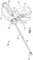
ここで、図1を参照すると、さまざまな外科手術処置における使用のための内視鏡鉗子10の実施形態が示され、一般的には、相互に協同して、管状血管および脈管組織を把持、密閉および分割するハウジング20、変換器アセンブリ30、エネルギーアセンブリ40、シャフトアセンブリ50、導波管アセンブリ60、トリガーアセンブリ70、回転アセンブリ80およびエンドエフェクタアセンブリ90を含む。 Referring now to FIG. 1, an embodiment of an
鉗子10は、エネルギーアセンブリ40が鉗子10に動作可能に接続された場合、エネルギーアセンブリ40によって電力供給される。エネルギーアセンブリ40は、エネルギー(例えば、電圧)をDCおよび/またはAC信号から鉗子10まで伝送するために、1つ以上のバッテリー42および/または1つ以上の電気外科ケーブル(示されていない)を含み得る。鉗子10は、バッテリーセルの充電および放電を制御し、図2に例示される変換器アセンブリ30と通信するスマートバッテリーを含み得る。そのような器具のより詳細な説明に対して、2009年11月12日に出願された共有に係る米国出願第12/269,544号に参照がなされる。 The
1つ以上の電気外科ケーブルを有している実施形態において、鉗子10は、電気外科エネルギーの外部供給源(例えば、電気外科発電機(示されていない))に接続可能である。1つのそのような電気外科エネルギー供給源は、名称が「ELECTROSURGICAL GENERATOR WITH ADAPTIVE POWER CONTROL」である共有に係る米国特許第6,033,399号に記載されている。 In embodiments having one or more electrosurgical cables, the
変換器アセンブリ30は、ハウジング20に動作可能に結合された1つ以上の超音波変換器(示されていない)を含む。ハウジング20内に位置決めされ得る各変換器は、エネルギーアセンブリ40から各変換器に伝達されたエネルギーを高周波数力学的運動(例えば、超音波振動)に変換する。そのため、1つ以上の変換器における超音波振動の周波数は、1つ以上の変換器に適用されたエネルギー信号(例えば高電圧AC信号)の周波数によって制御される。図3に描写されるように、この周波数制御は、変換器アセンブリ30における位相ロックループによって実現され得る。 The
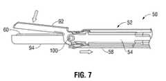
図4〜図7を参照すると、少なくとも部分的に使い捨てであり得るシャフトアセンブリ50がハウジング20から延在し、シャフトアセンブリ50を通る中央管腔50aを規定する(図5を参照)。中央管腔50aは、導波管アセンブリ60の少なくとも一部を中央管腔50aの中に受け取る。最もよく図5に描写されるように、シャフトアセンブリ50は、シャフト51、第一および第二の関節運動部材54、56およびクランプ締め部材58を含む。第一および第二の関節運動部材54、56およびクランプ締め部材58は、移動可能にシャフト51に沿って位置決めされる。シャフト51は、対向する遠位支持部材53を有している細長い本体52を含む。対抗する遠位支持部材53は、細長い本体52から延在する。支持部材53は、離間されており、各支持部材53は、旋回ピン110を係合するための、各支持部材53を通る開口部53aを規定する。特に、細長い本体52は、細長い本体52に沿って、チャネル52aを規定する。第一および第二の関節運動部材54、56の各々およびクランプ締め部材58は、移動可能にチャネル52a内に位置決めされる。より具体的には、第一および第二の関節運動部材54、56は、シャフト51に沿って、シャフト51の側面の対向する側上に位置決めされることによって、第一および第二の関節運動部材54、56は、長手方向にシャフト51の細長い本体52の対向する側沿って並進可能である。クランプ締め部材58は、シャフト51の底面に沿って、第一および第二の関節運動部材54、56に対して直角に配置される。そのため、クランプ締め部材58は、長手方向にシャフト51に沿って、第一および第二の関節運動部材54、56に対して直角に並進する。 4-7, a
継続して図5を参照すると、クランプ締め部材58は、クランプ締め部材58から延在する遠位駆動部材58aを含む。遠位駆動部材58aは、遠位駆動部材58aを通るアパーチャ58bを規定する。下記にさらに詳細に記載されるように、クランプ締め部材58の近位端部は、トリガーアセンブリ70の作動の際に、クランプ締め部材58をシャフトアセンブリ50のシャフト51に対して、長手方向に並進させるために、トリガーアセンブリ70に動作可能に結合される。 With continued reference to FIG. 5, the clamping
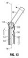
第一および第二の関節運動部材54、56の遠位端部は、エンドエフェクタアセンブリ90に動作可能に結合され、それぞれ第一および第二の関節運動部材54、56を通るボールスロット54a、56aを規定する。第一および第二の関節運動部材54、56は、エンドエフェクタアセンブリ90に動作可能に結合されるので、第一および第二の関節運動部材54、56は、シャフトアセンブリ50を通して規定された長手方向軸「A−A」(図12〜図13を参照)に対してエンドエフェクタアセンブリ90を関節運動させるか、および/またはエンドエフェクタアセンブリ90をシャフトアセンブリ50の長手方向軸「A−A」に沿って並進させる。 The distal ends of the first and
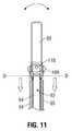
再び図1を参照すると、関節運動器22(例えば、ノブ、スイッチまたは当分野において既知である任意の他の適切な力学的制御器)がハウジング20に搭載され、第一および第二の関節運動部材54、56が、関節運動器22の軸および/または回転の移動に応答して、長手方向に移動するように、第一および第二の関節運動部材54、56の近位端部に動作可能に結合される。この点において、関節運動部材54、56の各々は、関節運動器22によって長手方向に並進可能であり、エンドエフェクタアセンブリ90を関節運動および/または並進させる。図12〜図13に示されるように、第一の関節運動部材54は、第二の関節運動部材56とは反対の方向に移動し、エンドエフェクタアセンブリ90を横方向に関節運動させる。そのため、エンドエフェクタアセンブリ90は、シャフトアセンブリ50に対して、シャフトアセンブリ50の長手方向軸「A−A」を横断する軸の周りに関節運動させるように構成され得る。さらに、第一および第二の関節運動部材54、56は、シャフトアセンブリ50の長手方向軸「A−A」に沿って、同時に延長および/または後退するように構成され得、エンドエフェクタアセンブリ90をシャフトアセンブリ50に対して、近位方向および/または遠位方向に移動させる。図10〜図11に描写されるように、シャフトおよび導波管アセンブリ50、60の周りのエンドエフェクタアセンブリ90の関節運動を容易にするために、エンドエフェクタアセンブリ90が導波管アセンブリ60に対して、導波管アセンブリ60の先端における線(線「D−D」として示される)を越える遠位位置まで長手方向に並進するように、両関節運動部材54、56は、同時に、同じ長手方向に移動する。 Referring again to FIG. 1, an articulator 22 (eg, a knob, switch or any other suitable mechanical controller known in the art) is mounted on the
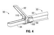
再び図5〜図7を参照すると、少なくとも部分的に使い捨てであり得るエンドエフェクタアセンブリ90は、1対の対向するジョー部材92、94を含む。第一のジョー部材92は、旋回アーム92aを含む。旋回アーム92aは、クランプ締め部材58の移動が第一のジョー部材92を第二のジョー部材94に対して旋回させ、ジョー92、94を接近された構成と接近されていない構成との間に位置決めするように、クランプ締め部材58の遠位駆動部材58a内に規定されたアパーチャ58bと係合可能である。 Referring again to FIGS. 5-7,
第一のジョー部材92は、第一のジョー部材92の近位端部上に旋回フランジ93を含む。旋回フランジ93は、旋回フランジ93の各側上にボールスロット93aを規定することによって、1対のボールベアリング100がそれぞれのボールスロット93aに結合され得る。ボールベアリング100は、下記でさらに詳細に記載される。旋回フランジ93は、クランプ締め部材58の遠位駆動部材58aと係合可能であり、第一のジョー部材92を第二のジョー部材94に対して移動させる旋回アーム122を含む。より具体的には、旋回アーム122は、遠位駆動部材58aのアパーチャ58b内に位置決め可能であることによって、第一のジョー部材92がシャフトアセンブリ50の長手方向軸「A−A」を横断する軸の周りを旋回し、第一のジョー部材92を第二のジョー部材94から回転させ、離す。クランプ締め部材58が最遠位位置に位置決めされた場合、第一のジョー部材92は、第二のジョー部材94に対して、接近されていない構成(開いている)にある。クランプ締め部材58が最近位位置にある場合、第一のジョー部材92は、第二のジョー部材94に対して、接近した構成(閉じている)にある。 The
第二のジョー部材94は、第二のジョー部材94を通るチャネル94aを規定する。第二のジョー部材94は、第二のジョー部材94を通るピンスロット94bと、第二のジョー部材94の近位端部の対向する側上のボールスロット96とを規定する。ボールスロット96は、ボールベアリング100をボールスロット96の中に係合するように構成されており、ボールベアリング100は、下記でより詳細に記載される。旋回スロット94bは、シャフト51の支持部材53の開口部53aと整列し、シャフトアセンブリ50に対するエンドエフェクタアセンブリ90の関節運動をさらに容易にするために、旋回ピン110を旋回スロット94bを通して受け取る。この点において、エンドエフェクタアセンブリ90は、シャフトアセンブリ50の長手方向軸「A−A」を横断する軸の周りを旋回可能にされる。 The
ジョー部材92、94は、例えば、アルミニウムおよびアルミニウムの合金、メッキされた真鍮、ステンレス鋼、ステンレス鋼合金、ベリリウム銅などのような金属材料といった任意の適切な材料から形成され得るが、それらに限定されない。他の実施形態において、1つまたは両方のジョー部材92および94は、可鍛性または可撓性特性を有している材料から形成され得るか、あるいは、ジョー部材92および94のうちの1つまたは両方は、非可撓性特性を有している材料から形成され得る。 The
ボールベアリング100は、シャフト部材50の関節運動部材54、56と、第二のジョーにおいて規定されたボールスロット96とを係合するように構成されており、エンドエフェクタアセンブリ90がシャフトアセンブリ50に対して関節運動させることを可能にする。このようにして、関節運動部材54、56は、ボールベアリング100の外面に沿って移動し、エンドエフェクタアセンブリ90の関節運動を容易にする。 The
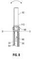
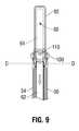
図8〜図9に最もよく描写されるように、導波管アセンブリ60は、シャフトアセンブリ50内に位置決めされ、1つ以上の変換器によって生成された超音波力学的振動を受け取ることと、伝達することとを行うように構成されている。導波管アセンブリ60は、導波管62と、導波管62の遠位端部に動作可能に結合された超音波治療部材64とを含む。導波管アセンブリ60は、少なくとも部分的に、エンドエフェクタアセンブリ90の1つまたは両方のジョー部材92、94内に位置決め可能である。より具体的には、超音波治療部材64の少なくとも一部は、エンドエフェクタアセンブリ90のジョー部材94によって規定されたチャネル94a内に位置決め可能である。図9を参照すると、超音波治療部材64がエンドエフェクタアセンブリ90の近位にある線(線「D−D」として示される)を越えるチャネル94a内に位置決めされた場合、エンドエフェクタアセンブリ90は、関節運動が妨げられる。しかし、超音波治療部材64が線(導波管アセンブリ60の先端における線「D−D」として、図8に示される)の後ろに、近位方向に位置決めされた場合、シャフトおよび導波管アセンブリ50、60の周りのエンドエフェクタアセンブリ90の関節運動は容易にされる。いくつかの実施形態において、超音波治療部材64は、導波管62の遠位端部に一体的に形成される。いくつかの実施形態において、超音波治療部材64は、移動可能に導波管62の遠位端部に結合され得る。超音波治療部材64は、力学的振動を1つ以上の変換器から受け取ることと、エンドエフェクタアセンブリ90内に位置決めされた組織を治療するために、力学的振動を伝達することとを行うように構成されている。導波管アセンブリ60は、エンドエフェクタアセンブリ90に対して、長手方向に並進可能であり得る。 As best depicted in FIGS. 8-9, the
回転アセンブリ80は、ハウジング20に動作するように接続され、どちらか一方の方向に、シャフトアセンブリ50の長手方向軸の周りを回転可能であり、シャフトアセンブリ50およびエンドエフェクタアセンブリ90をシャフトアセンブリ50の長手方向軸の周りに回転させる。このことは、ユーザーが作動および密閉するまえに、鉗子10を位置決めおよび再位置決めすることを可能にする。回転アセンブリ80は、シャフトアセンブリ50に動作可能に結合される。回転アセンブリ80のより詳細な説明は、Dycusらによる、名称が「VESSEL SEALER AND DIVIDER」の米国特許第7,101,371号に記載される。 The rotating assembly 80 is operatively connected to the
トリガーアセンブリ70は、エネルギーをエネルギーアセンブリ40から作動させる作動トリガー72と、エンドエフェクタアセンブリ90を動作させるクランプ締めトリガー74とを含む。トリガーアセンブリ70は、ハウジング20に動作可能に結合される。作動トリガー72は、1つ以上の変換器の作動の際に、エネルギー供給源から1つ以上の変換器へのエネルギーの伝達を容易にするように構成されている。クランプ締めトリガー74は、クランプ締めトリガー74の作動の際に、対向するジョー部材92、94を接近されていない構成と接近された構成との間に移動させるために、クランプ締め部材58を移動させるように構成されている。このようにして、トリガーアセンブリ70のクランプ締めトリガー74は、シャフトアセンブリ50に動作するように接続され、第一および第二のジョー部材92、94を、ジョー部材92、94が互いに対して一定の距離を置かれた接近されていない(開いている)位置から、ジョー部材92、94が協同してジョー部材92、94の間の組織を把持するクランプ締めまたは接近された(閉じている)位置まで移動させる。 The
使用において、作動トリガー72が作動された場合、エネルギーアセンブリ40は、エネルギー(例えば、高電圧AC信号)を変換器アセンブリ30に適用する。上記で述べたように、次いで、第一および第二のジョー92、94との間に把持された組織を超音波振動によって治療するために、エネルギーは、変換器アセンブリ30によって変換され、変換器アセンブリ30から導波管アセンブリ60に沿って、エンドエフェクタアセンブリ90まで伝達される。 In use, when the activation trigger 72 is activated, the
この目的を念頭に置いて、鉗子10が意図したように機能し得るように、鉗子10は、任意の適切な数の電気接続、構成および/または部品(例えば、抵抗器、コンデンサー、誘導器、加減抵抗器など)、機械接続、構成および/または部品(例えば、ギア、リンク、スプリング、部材など)、ならびに/もしくは、電気機械接続、構成および/または部品を含み得る。 With this purpose in mind, the
開示の複数の実施形態が図面において示されたが、開示がそれらに限定されることは意図されておらず、開示は、当業者が許容する限り範囲が広いことが意図されており、明細書も同様に読まれることが意図される。そのため、上記説明は、限定的とではなく、特定の実施形態の例示に過ぎないと解釈されるべきである。当業者は、本明細書に添付の請求項の範囲および精神内に他の改変を想定する。 While embodiments of the disclosure have been shown in the drawings, the disclosure is not intended to be limited thereto, and the disclosure is intended to be as broad as the skilled person would Are intended to be read as well. Therefore, the above description should not be construed as limiting, but merely as exemplifications of particular embodiments. Those skilled in the art will envision other modifications within the scope and spirit of the claims appended hereto.
Claims (19)
Translated fromJapanese該ハウジングから延在するシャフトアセンブリであって、該シャフトアセンブリは、少なくとも1つの関節運動部材と、少なくとも1つのクランプ締め部材と、該シャフトアセンブリを通って規定される長手方向軸とを含む、シャフトアセンブリと、
該シャフトアセンブリの遠位端部に配置されたエンドエフェクタアセンブリであって、該エンドエフェクタアセンブリは、該少なくとも1つのクランプ締め部材の移動に応答して、接近された構成と接近されていない構成との間を旋回可能な1対の対向するジョー部材を含み、該少なくとも1つの関節運動部材は、該1対の対向するジョー部材を該シャフトアセンブリの長手方向軸に対して関節運動させるように構成されている、エンドエフェクタアセンブリと、
該シャフトアセンブリ内に位置決めされた導波管アセンブリであって、該導波管アセンブリは、該変換器によって生成された該力学的振動を受け取るように構成されており、該導波管アセンブリは、該対向するジョー部材のうちの少なくとも1つ内に少なくとも部分的に位置決め可能である、導波管アセンブリと
を含む鉗子であって、
ここで、該エンドエフェクタは、該シャフトアセンブリおよび該導波管アセンブリに対して、近位位置と遠位位置との間で長手方向に並進可能であり、該エンドエフェクタアセンブリが該遠位位置に配置される場合、該エンドエフェクタアセンブリが、該シャフトアセンブリおよび該導波管アセンブリに対して関節運動することを可能にする、鉗子。A housing having at least one transducer, wherein the at least one transducer is responsive to energy transferred from an energy source to the at least one transducer to generate a mechanical vibration. A housing,
A shaft assembly extending from the housing, the shaft assembly including at least one articulation member, at least one clamping member, and a longitudinal axis defined through the shaft assembly. Assembly,
An end effector assembly disposed at a distal end of the shaft assembly, the end effector assembly being in an approached configuration and an inaccessible configuration in response to movement of the at least one clamping member; A pair of opposing jaw members pivotable between, wherein the at least one articulating member is configured to articulate the pair of opposing jaw members relative to a longitudinal axis of the shaft assembly An end effector assembly,
A waveguide assembly positioned within the shaft assembly, the waveguide assembly configured to receive the mechanical vibrations generated by the transducer, the waveguide assembly comprising: A forceps assembly comprising: a waveguide assembly positionable at least partially within at least one of the opposing jaw members;
Here, the end effector is longitudinally translatable with respect to the shaft assembly and the waveguide assembly between a proximal position and a distal position, and the end effector assembly is in the distal position. Forceps that, when deployed, allow the end effector assembly to articulate relative to the shaft assembly and the waveguide assembly.
該ハウジングから延在するシャフトアセンブリであって、該シャフトアセンブリは、長手方向軸を規定し、少なくとも1つの関節運動部材と、少なくとも1つのクランプ締め部材とを含む、シャフトアセンブリと、
該シャフトアセンブリ内に位置決めされた導波管アセンブリであって、該変換器によって生成された該力学的振動を受け取るように構成されている、導波管アセンブリと、
該シャフトアセンブリの遠位端部に配置されたエンドエフェクタアセンブリであって、該エンドエフェクタアセンブリは、該少なくとも1つのクランプ締め部材の移動に応答して、接近された構成と接近されていない構成との間を旋回可能な1対の対向するジョー部材を含み、該少なくとも1つの関節運動部材は、該1対の対向するジョー部材を該シャフトアセンブリの長手方向軸に対して関節運動させるように構成されており、該エンドエフェクタアセンブリは、該シャフトアセンブリおよび該導波管アセンブリに対して、近位位置と遠位位置との間で長手方向に並進可能であり、該エンドエフェクタアセンブリが該遠位位置に配置される場合、該エンドエフェクタアセンブリが、該シャフトアセンブリおよび該導波管アセンブリに対して関節運動することを可能にする、エンドエフェクタアセンブリ
とを含む鉗子であって、
該導波管アセンブリは、該対向するジョー部材のうちの少なくとも1つ内に少なくとも部分的に位置決め可能である、鉗子。A housing having at least one transducer, wherein the at least one transducer is responsive to energy transferred from an energy source to the at least one transducer to generate a mechanical vibration. A housing,
A shaft assembly extending from the housing, the shaft assembly defining a longitudinal axis and including at least one articulation member and at least one clamping member;
A waveguide assembly positioned within the shaft assembly, the waveguide assembly configured to receive the mechanical vibrations generated by the transducer;
An end effector assembly disposed at a distal end of the shaft assembly, the end effector assembly being in an approached configuration and an inaccessible configuration in response to movement of the at least one clamping member; A pair of opposing jaw members pivotable between, wherein the at least one articulating member is configured to articulate the pair of opposing jaw members relative to a longitudinal axis of the shaft assembly The end effectorassembly is longitudinally translatable with respect to the shaft assembly and the waveguide assembly between a proximal position and a distal position, the end effector assembly being at the distal end The end effector assembly relative to the shaft assembly and the waveguide assembly when positioned in position. Make it possible to section movement, a forceps that includes an end effector assembly,
The waveguide assembly is at least partially positionable within at least one of the jawmember to the opposite, forceps.
Applications Claiming Priority (2)
| Application Number | Priority Date | Filing Date | Title |
|---|---|---|---|
| US13/108,117US8444664B2 (en) | 2011-05-16 | 2011-05-16 | Medical ultrasound instrument with articulated jaws |
| US13/108,117 | 2011-05-16 |
Publications (3)
| Publication Number | Publication Date |
|---|---|
| JP2012239901A JP2012239901A (en) | 2012-12-10 |
| JP2012239901A5 JP2012239901A5 (en) | 2013-08-29 |
| JP5404849B2true JP5404849B2 (en) | 2014-02-05 |
Family
ID=46177335
Family Applications (1)
| Application Number | Title | Priority Date | Filing Date |
|---|---|---|---|
| JP2012112420AExpired - Fee RelatedJP5404849B2 (en) | 2011-05-16 | 2012-05-16 | Medical ultrasonic instrument having articulated jaws |
Country Status (5)
| Country | Link |
|---|---|
| US (2) | US8444664B2 (en) |
| EP (1) | EP2524660B1 (en) |
| JP (1) | JP5404849B2 (en) |
| AU (1) | AU2012202874B2 (en) |
| CA (1) | CA2776755C (en) |
Cited By (1)
| Publication number | Priority date | Publication date | Assignee | Title |
|---|---|---|---|---|
| WO2016003025A1 (en)* | 2014-07-01 | 2016-01-07 | 한희상 | Clip tip rotation-type medical ultrasonic cutter |
Families Citing this family (212)
| Publication number | Priority date | Publication date | Assignee | Title |
|---|---|---|---|---|
| US11229472B2 (en) | 2001-06-12 | 2022-01-25 | Cilag Gmbh International | Modular battery powered handheld surgical instrument with multiple magnetic position sensors |
| US8182501B2 (en) | 2004-02-27 | 2012-05-22 | Ethicon Endo-Surgery, Inc. | Ultrasonic surgical shears and method for sealing a blood vessel using same |
| US20060079879A1 (en) | 2004-10-08 | 2006-04-13 | Faller Craig N | Actuation mechanism for use with an ultrasonic surgical instrument |
| US20070191713A1 (en) | 2005-10-14 | 2007-08-16 | Eichmann Stephen E | Ultrasonic device for cutting and coagulating |
| US7621930B2 (en) | 2006-01-20 | 2009-11-24 | Ethicon Endo-Surgery, Inc. | Ultrasound medical instrument having a medical ultrasonic blade |
| US8911460B2 (en) | 2007-03-22 | 2014-12-16 | Ethicon Endo-Surgery, Inc. | Ultrasonic surgical instruments |
| US8057498B2 (en) | 2007-11-30 | 2011-11-15 | Ethicon Endo-Surgery, Inc. | Ultrasonic surgical instrument blades |
| US8142461B2 (en) | 2007-03-22 | 2012-03-27 | Ethicon Endo-Surgery, Inc. | Surgical instruments |
| US8226675B2 (en) | 2007-03-22 | 2012-07-24 | Ethicon Endo-Surgery, Inc. | Surgical instruments |
| US8808319B2 (en) | 2007-07-27 | 2014-08-19 | Ethicon Endo-Surgery, Inc. | Surgical instruments |
| US8523889B2 (en) | 2007-07-27 | 2013-09-03 | Ethicon Endo-Surgery, Inc. | Ultrasonic end effectors with increased active length |
| US8882791B2 (en) | 2007-07-27 | 2014-11-11 | Ethicon Endo-Surgery, Inc. | Ultrasonic surgical instruments |
| US9044261B2 (en) | 2007-07-31 | 2015-06-02 | Ethicon Endo-Surgery, Inc. | Temperature controlled ultrasonic surgical instruments |
| US8512365B2 (en) | 2007-07-31 | 2013-08-20 | Ethicon Endo-Surgery, Inc. | Surgical instruments |
| US8430898B2 (en) | 2007-07-31 | 2013-04-30 | Ethicon Endo-Surgery, Inc. | Ultrasonic surgical instruments |
| EP2217157A2 (en) | 2007-10-05 | 2010-08-18 | Ethicon Endo-Surgery, Inc. | Ergonomic surgical instruments |
| US10010339B2 (en) | 2007-11-30 | 2018-07-03 | Ethicon Llc | Ultrasonic surgical blades |
| US9089360B2 (en) | 2008-08-06 | 2015-07-28 | Ethicon Endo-Surgery, Inc. | Devices and techniques for cutting and coagulating tissue |
| US9700339B2 (en) | 2009-05-20 | 2017-07-11 | Ethicon Endo-Surgery, Inc. | Coupling arrangements and methods for attaching tools to ultrasonic surgical instruments |
| US8663220B2 (en) | 2009-07-15 | 2014-03-04 | Ethicon Endo-Surgery, Inc. | Ultrasonic surgical instruments |
| US9168054B2 (en) | 2009-10-09 | 2015-10-27 | Ethicon Endo-Surgery, Inc. | Surgical generator for ultrasonic and electrosurgical devices |
| USRE47996E1 (en) | 2009-10-09 | 2020-05-19 | Ethicon Llc | Surgical generator for ultrasonic and electrosurgical devices |
| US11090104B2 (en) | 2009-10-09 | 2021-08-17 | Cilag Gmbh International | Surgical generator for ultrasonic and electrosurgical devices |
| US10172669B2 (en) | 2009-10-09 | 2019-01-08 | Ethicon Llc | Surgical instrument comprising an energy trigger lockout |
| US10441345B2 (en) | 2009-10-09 | 2019-10-15 | Ethicon Llc | Surgical generator for ultrasonic and electrosurgical devices |
| US9050093B2 (en) | 2009-10-09 | 2015-06-09 | Ethicon Endo-Surgery, Inc. | Surgical generator for ultrasonic and electrosurgical devices |
| US8951272B2 (en) | 2010-02-11 | 2015-02-10 | Ethicon Endo-Surgery, Inc. | Seal arrangements for ultrasonically powered surgical instruments |
| US8961547B2 (en) | 2010-02-11 | 2015-02-24 | Ethicon Endo-Surgery, Inc. | Ultrasonic surgical instruments with moving cutting implement |
| US8486096B2 (en) | 2010-02-11 | 2013-07-16 | Ethicon Endo-Surgery, Inc. | Dual purpose surgical instrument for cutting and coagulating tissue |
| US8579928B2 (en) | 2010-02-11 | 2013-11-12 | Ethicon Endo-Surgery, Inc. | Outer sheath and blade arrangements for ultrasonic surgical instruments |
| US8469981B2 (en) | 2010-02-11 | 2013-06-25 | Ethicon Endo-Surgery, Inc. | Rotatable cutting implement arrangements for ultrasonic surgical instruments |
| US8834518B2 (en) | 2010-04-12 | 2014-09-16 | Ethicon Endo-Surgery, Inc. | Electrosurgical cutting and sealing instruments with cam-actuated jaws |
| GB2480498A (en) | 2010-05-21 | 2011-11-23 | Ethicon Endo Surgery Inc | Medical device comprising RF circuitry |
| US8795327B2 (en) | 2010-07-22 | 2014-08-05 | Ethicon Endo-Surgery, Inc. | Electrosurgical instrument with separate closure and cutting members |
| US9192431B2 (en) | 2010-07-23 | 2015-11-24 | Ethicon Endo-Surgery, Inc. | Electrosurgical cutting and sealing instrument |
| US8979890B2 (en) | 2010-10-01 | 2015-03-17 | Ethicon Endo-Surgery, Inc. | Surgical instrument with jaw member |
| EP2627278B1 (en) | 2010-10-11 | 2015-03-25 | Ecole Polytechnique Fédérale de Lausanne (EPFL) | Mechanical manipulator for surgical instruments |
| US12402960B2 (en) | 2010-10-11 | 2025-09-02 | Ecole Polytechnique Federale De Lausanne (Epfl) | Mechanical manipulator for surgical instruments |
| WO2013014621A2 (en) | 2011-07-27 | 2013-01-31 | Ecole Polytechnique Federale De Lausanne (Epfl) | Mechanical teleoperated device for remote manipulation |
| US9114181B2 (en) | 2011-03-30 | 2015-08-25 | Covidien Lp | Process of cooling surgical device battery before or during high temperature sterilization |
| WO2012135721A1 (en) | 2011-03-30 | 2012-10-04 | Tyco Healthcare Group Lp | Ultrasonic surgical instruments |
| US10729458B2 (en) | 2011-03-30 | 2020-08-04 | Covidien Lp | Ultrasonic surgical instruments |
| US8974479B2 (en) | 2011-03-30 | 2015-03-10 | Covidien Lp | Ultrasonic surgical instruments |
| US9259265B2 (en) | 2011-07-22 | 2016-02-16 | Ethicon Endo-Surgery, Llc | Surgical instruments for tensioning tissue |
| US9044243B2 (en) | 2011-08-30 | 2015-06-02 | Ethcon Endo-Surgery, Inc. | Surgical cutting and fastening device with descendible second trigger arrangement |
| US8974478B2 (en) | 2011-09-20 | 2015-03-10 | Covidien Lp | Ultrasonic surgical system having a fluid cooled blade and related cooling methods therefor |
| US20130085419A1 (en) | 2011-09-29 | 2013-04-04 | Tyco Healthcare Group Lp | Transducer/Waveguide Engagement Mechanisms for Ultrasonic Surgical Instruments |
| US9333025B2 (en) | 2011-10-24 | 2016-05-10 | Ethicon Endo-Surgery, Llc | Battery initialization clip |
| WO2013119545A1 (en) | 2012-02-10 | 2013-08-15 | Ethicon-Endo Surgery, Inc. | Robotically controlled surgical instrument |
| US9724118B2 (en) | 2012-04-09 | 2017-08-08 | Ethicon Endo-Surgery, Llc | Techniques for cutting and coagulating tissue for ultrasonic surgical instruments |
| US9439668B2 (en) | 2012-04-09 | 2016-09-13 | Ethicon Endo-Surgery, Llc | Switch arrangements for ultrasonic surgical instruments |
| US9237921B2 (en) | 2012-04-09 | 2016-01-19 | Ethicon Endo-Surgery, Inc. | Devices and techniques for cutting and coagulating tissue |
| US9241731B2 (en) | 2012-04-09 | 2016-01-26 | Ethicon Endo-Surgery, Inc. | Rotatable electrical connection for ultrasonic surgical instruments |
| US9226766B2 (en) | 2012-04-09 | 2016-01-05 | Ethicon Endo-Surgery, Inc. | Serial communication protocol for medical device |
| US20140005705A1 (en) | 2012-06-29 | 2014-01-02 | Ethicon Endo-Surgery, Inc. | Surgical instruments with articulating shafts |
| US9283045B2 (en) | 2012-06-29 | 2016-03-15 | Ethicon Endo-Surgery, Llc | Surgical instruments with fluid management system |
| US20140005702A1 (en) | 2012-06-29 | 2014-01-02 | Ethicon Endo-Surgery, Inc. | Ultrasonic surgical instruments with distally positioned transducers |
| US9326788B2 (en) | 2012-06-29 | 2016-05-03 | Ethicon Endo-Surgery, Llc | Lockout mechanism for use with robotic electrosurgical device |
| US9408622B2 (en) | 2012-06-29 | 2016-08-09 | Ethicon Endo-Surgery, Llc | Surgical instruments with articulating shafts |
| US9393037B2 (en) | 2012-06-29 | 2016-07-19 | Ethicon Endo-Surgery, Llc | Surgical instruments with articulating shafts |
| US9198714B2 (en) | 2012-06-29 | 2015-12-01 | Ethicon Endo-Surgery, Inc. | Haptic feedback devices for surgical robot |
| US9820768B2 (en) | 2012-06-29 | 2017-11-21 | Ethicon Llc | Ultrasonic surgical instruments with control mechanisms |
| US9226767B2 (en) | 2012-06-29 | 2016-01-05 | Ethicon Endo-Surgery, Inc. | Closed feedback control for electrosurgical device |
| US9351754B2 (en)* | 2012-06-29 | 2016-05-31 | Ethicon Endo-Surgery, Llc | Ultrasonic surgical instruments with distally positioned jaw assemblies |
| US9301798B2 (en)* | 2012-07-19 | 2016-04-05 | Covidien Lp | Surgical forceps including reposable end effector assemblies |
| US9161769B2 (en) | 2012-07-30 | 2015-10-20 | Covidien Lp | Endoscopic instrument |
| EP2900158B1 (en) | 2012-09-28 | 2020-04-15 | Ethicon LLC | Multi-function bi-polar forceps |
| US9241732B2 (en) | 2012-10-16 | 2016-01-26 | Covdien LP | Surgical instrument |
| US10201365B2 (en) | 2012-10-22 | 2019-02-12 | Ethicon Llc | Surgeon feedback sensing and display methods |
| US9095367B2 (en) | 2012-10-22 | 2015-08-04 | Ethicon Endo-Surgery, Inc. | Flexible harmonic waveguides/blades for surgical instruments |
| US20140135804A1 (en) | 2012-11-15 | 2014-05-15 | Ethicon Endo-Surgery, Inc. | Ultrasonic and electrosurgical devices |
| CN105073045A (en) | 2013-03-13 | 2015-11-18 | 柯惠Lp公司 | Clamp ultrasound probe for lung surgery |
| US10226273B2 (en) | 2013-03-14 | 2019-03-12 | Ethicon Llc | Mechanical fasteners for use with surgical energy devices |
| US9241728B2 (en) | 2013-03-15 | 2016-01-26 | Ethicon Endo-Surgery, Inc. | Surgical instrument with multiple clamping mechanisms |
| DE102013106446A1 (en)* | 2013-06-20 | 2014-12-24 | How To Organize (H2O) Gmbh | Endoscopic instrument |
| US9814514B2 (en) | 2013-09-13 | 2017-11-14 | Ethicon Llc | Electrosurgical (RF) medical instruments for cutting and coagulating tissue |
| US9265926B2 (en) | 2013-11-08 | 2016-02-23 | Ethicon Endo-Surgery, Llc | Electrosurgical devices |
| WO2015081038A1 (en)* | 2013-11-26 | 2015-06-04 | Ethicon Endo-Surgery, Inc. | Features to apply fluid to an ultrasonic blade of a surgical instrument |
| GB2521229A (en) | 2013-12-16 | 2015-06-17 | Ethicon Endo Surgery Inc | Medical device |
| GB2521228A (en) | 2013-12-16 | 2015-06-17 | Ethicon Endo Surgery Inc | Medical device |
| US9743946B2 (en) | 2013-12-17 | 2017-08-29 | Ethicon Llc | Rotation features for ultrasonic surgical instrument |
| US9795436B2 (en) | 2014-01-07 | 2017-10-24 | Ethicon Llc | Harvesting energy from a surgical generator |
| CN106659540B (en) | 2014-02-03 | 2019-03-05 | 迪斯塔莫申股份公司 | Mechanical teleoperated devices including interchangeable distal instruments |
| US9554854B2 (en) | 2014-03-18 | 2017-01-31 | Ethicon Endo-Surgery, Llc | Detecting short circuits in electrosurgical medical devices |
| US10092310B2 (en) | 2014-03-27 | 2018-10-09 | Ethicon Llc | Electrosurgical devices |
| US10463421B2 (en) | 2014-03-27 | 2019-11-05 | Ethicon Llc | Two stage trigger, clamp and cut bipolar vessel sealer |
| US10524852B1 (en) | 2014-03-28 | 2020-01-07 | Ethicon Llc | Distal sealing end effector with spacers |
| US9737355B2 (en) | 2014-03-31 | 2017-08-22 | Ethicon Llc | Controlling impedance rise in electrosurgical medical devices |
| EP3132764B1 (en) | 2014-04-15 | 2022-01-12 | Olympus Corporation | Energy treatment device |
| US9913680B2 (en) | 2014-04-15 | 2018-03-13 | Ethicon Llc | Software algorithms for electrosurgical instruments |
| US9757186B2 (en) | 2014-04-17 | 2017-09-12 | Ethicon Llc | Device status feedback for bipolar tissue spacer |
| US10667835B2 (en)* | 2014-04-22 | 2020-06-02 | Ethicon Llc | Ultrasonic surgical instrument with end effector having restricted articulation |
| US9700333B2 (en) | 2014-06-30 | 2017-07-11 | Ethicon Llc | Surgical instrument with variable tissue compression |
| US10285724B2 (en) | 2014-07-31 | 2019-05-14 | Ethicon Llc | Actuation mechanisms and load adjustment assemblies for surgical instruments |
| US9877776B2 (en) | 2014-08-25 | 2018-01-30 | Ethicon Llc | Simultaneous I-beam and spring driven cam jaw closure mechanism |
| US10194976B2 (en) | 2014-08-25 | 2019-02-05 | Ethicon Llc | Lockout disabling mechanism |
| US10194972B2 (en) | 2014-08-26 | 2019-02-05 | Ethicon Llc | Managing tissue treatment |
| EP3185808B1 (en) | 2014-08-27 | 2022-02-23 | DistalMotion SA | Surgical system for microsurgical techniques |
| US11207127B2 (en) | 2014-09-25 | 2021-12-28 | Covidien Lp | Surgical instruments facilitating replacement of disposable components and/or sterilization of reusable components |
| US10639092B2 (en) | 2014-12-08 | 2020-05-05 | Ethicon Llc | Electrode configurations for surgical instruments |
| WO2016097871A1 (en) | 2014-12-19 | 2016-06-23 | Distalmotion Sa | Docking system for mechanical telemanipulator |
| EP3232951B1 (en) | 2014-12-19 | 2023-10-25 | DistalMotion SA | Surgical instrument with articulated end-effector |
| WO2016097873A2 (en) | 2014-12-19 | 2016-06-23 | Distalmotion Sa | Articulated handle for mechanical telemanipulator |
| EP3653145B1 (en) | 2014-12-19 | 2024-01-24 | DistalMotion SA | Reusable surgical instrument for minimally invasive procedures |
| WO2016097861A1 (en) | 2014-12-19 | 2016-06-23 | Distalmotion Sa | Sterile interface for articulated surgical instruments |
| US10092348B2 (en) | 2014-12-22 | 2018-10-09 | Ethicon Llc | RF tissue sealer, shear grip, trigger lock mechanism and energy activation |
| US10111699B2 (en) | 2014-12-22 | 2018-10-30 | Ethicon Llc | RF tissue sealer, shear grip, trigger lock mechanism and energy activation |
| US9848937B2 (en) | 2014-12-22 | 2017-12-26 | Ethicon Llc | End effector with detectable configurations |
| US10159524B2 (en) | 2014-12-22 | 2018-12-25 | Ethicon Llc | High power battery powered RF amplifier topology |
| US10245095B2 (en) | 2015-02-06 | 2019-04-02 | Ethicon Llc | Electrosurgical instrument with rotation and articulation mechanisms |
| US10653476B2 (en) | 2015-03-12 | 2020-05-19 | Covidien Lp | Mapping vessels for resecting body tissue |
| US10342602B2 (en) | 2015-03-17 | 2019-07-09 | Ethicon Llc | Managing tissue treatment |
| US10321950B2 (en) | 2015-03-17 | 2019-06-18 | Ethicon Llc | Managing tissue treatment |
| US10595929B2 (en) | 2015-03-24 | 2020-03-24 | Ethicon Llc | Surgical instruments with firing system overload protection mechanisms |
| US10314638B2 (en) | 2015-04-07 | 2019-06-11 | Ethicon Llc | Articulating radio frequency (RF) tissue seal with articulating state sensing |
| US10568709B2 (en) | 2015-04-09 | 2020-02-25 | Distalmotion Sa | Mechanical teleoperated device for remote manipulation |
| EP3280337B1 (en) | 2015-04-09 | 2019-11-13 | DistalMotion SA | Articulated hand-held instrument |
| US10117702B2 (en) | 2015-04-10 | 2018-11-06 | Ethicon Llc | Surgical generator systems and related methods |
| US10130410B2 (en) | 2015-04-17 | 2018-11-20 | Ethicon Llc | Electrosurgical instrument including a cutting member decouplable from a cutting member trigger |
| US9872725B2 (en) | 2015-04-29 | 2018-01-23 | Ethicon Llc | RF tissue sealer with mode selection |
| US10034684B2 (en) | 2015-06-15 | 2018-07-31 | Ethicon Llc | Apparatus and method for dissecting and coagulating tissue |
| US11020140B2 (en) | 2015-06-17 | 2021-06-01 | Cilag Gmbh International | Ultrasonic surgical blade for use with ultrasonic surgical instruments |
| US11141213B2 (en) | 2015-06-30 | 2021-10-12 | Cilag Gmbh International | Surgical instrument with user adaptable techniques |
| US10898256B2 (en) | 2015-06-30 | 2021-01-26 | Ethicon Llc | Surgical system with user adaptable techniques based on tissue impedance |
| US11129669B2 (en) | 2015-06-30 | 2021-09-28 | Cilag Gmbh International | Surgical system with user adaptable techniques based on tissue type |
| US11051873B2 (en) | 2015-06-30 | 2021-07-06 | Cilag Gmbh International | Surgical system with user adaptable techniques employing multiple energy modalities based on tissue parameters |
| US10034704B2 (en) | 2015-06-30 | 2018-07-31 | Ethicon Llc | Surgical instrument with user adaptable algorithms |
| US10357303B2 (en) | 2015-06-30 | 2019-07-23 | Ethicon Llc | Translatable outer tube for sealing using shielded lap chole dissector |
| US10154852B2 (en) | 2015-07-01 | 2018-12-18 | Ethicon Llc | Ultrasonic surgical blade with improved cutting and coagulation features |
| CN209122435U (en) | 2015-07-17 | 2019-07-19 | 柯惠有限合伙公司 | An end effector assembly |
| WO2017037532A1 (en) | 2015-08-28 | 2017-03-09 | Distalmotion Sa | Surgical instrument with increased actuation force |
| US10194973B2 (en) | 2015-09-30 | 2019-02-05 | Ethicon Llc | Generator for digitally generating electrical signal waveforms for electrosurgical and ultrasonic surgical instruments |
| US10595930B2 (en) | 2015-10-16 | 2020-03-24 | Ethicon Llc | Electrode wiping surgical device |
| US10959771B2 (en) | 2015-10-16 | 2021-03-30 | Ethicon Llc | Suction and irrigation sealing grasper |
| JP6099856B1 (en)* | 2015-10-28 | 2017-03-22 | オリンパス株式会社 | Grasping treatment instrument |
| US10245057B2 (en) | 2015-10-28 | 2019-04-02 | Covidien Lp | Surgical instruments including knife assemblies with reducible cutting height |
| US10179022B2 (en) | 2015-12-30 | 2019-01-15 | Ethicon Llc | Jaw position impedance limiter for electrosurgical instrument |
| US10959806B2 (en) | 2015-12-30 | 2021-03-30 | Ethicon Llc | Energized medical device with reusable handle |
| US10575892B2 (en) | 2015-12-31 | 2020-03-03 | Ethicon Llc | Adapter for electrical surgical instruments |
| US11051840B2 (en) | 2016-01-15 | 2021-07-06 | Ethicon Llc | Modular battery powered handheld surgical instrument with reusable asymmetric handle housing |
| US10716615B2 (en) | 2016-01-15 | 2020-07-21 | Ethicon Llc | Modular battery powered handheld surgical instrument with curved end effectors having asymmetric engagement between jaw and blade |
| US12193698B2 (en) | 2016-01-15 | 2025-01-14 | Cilag Gmbh International | Method for self-diagnosing operation of a control switch in a surgical instrument system |
| US11229471B2 (en) | 2016-01-15 | 2022-01-25 | Cilag Gmbh International | Modular battery powered handheld surgical instrument with selective application of energy based on tissue characterization |
| US11129670B2 (en) | 2016-01-15 | 2021-09-28 | Cilag Gmbh International | Modular battery powered handheld surgical instrument with selective application of energy based on button displacement, intensity, or local tissue characterization |
| US20170209206A1 (en) | 2016-01-23 | 2017-07-27 | Covidien Lp | Devices and methods for tissue sealing and mechanical clipping |
| US10555769B2 (en) | 2016-02-22 | 2020-02-11 | Ethicon Llc | Flexible circuits for electrosurgical instrument |
| US10456156B2 (en)* | 2016-03-29 | 2019-10-29 | Covidien Lp | Devices, systems, and methods for cooling a surgical instrument |
| US10702329B2 (en) | 2016-04-29 | 2020-07-07 | Ethicon Llc | Jaw structure with distal post for electrosurgical instruments |
| US10646269B2 (en) | 2016-04-29 | 2020-05-12 | Ethicon Llc | Non-linear jaw gap for electrosurgical instruments |
| US10987156B2 (en) | 2016-04-29 | 2021-04-27 | Ethicon Llc | Electrosurgical instrument with electrically conductive gap setting member and electrically insulative tissue engaging members |
| US10856934B2 (en) | 2016-04-29 | 2020-12-08 | Ethicon Llc | Electrosurgical instrument with electrically conductive gap setting and tissue engaging members |
| US10485607B2 (en) | 2016-04-29 | 2019-11-26 | Ethicon Llc | Jaw structure with distal closure for electrosurgical instruments |
| US10456193B2 (en) | 2016-05-03 | 2019-10-29 | Ethicon Llc | Medical device with a bilateral jaw configuration for nerve stimulation |
| US10245064B2 (en) | 2016-07-12 | 2019-04-02 | Ethicon Llc | Ultrasonic surgical instrument with piezoelectric central lumen transducer |
| US10893883B2 (en) | 2016-07-13 | 2021-01-19 | Ethicon Llc | Ultrasonic assembly for use with ultrasonic surgical instruments |
| US10842522B2 (en) | 2016-07-15 | 2020-11-24 | Ethicon Llc | Ultrasonic surgical instruments having offset blades |
| DE102016213001A1 (en) | 2016-07-15 | 2018-01-18 | Robert Bosch Gmbh | A light emitting device and method of manufacturing a light emitting device |
| US10376305B2 (en) | 2016-08-05 | 2019-08-13 | Ethicon Llc | Methods and systems for advanced harmonic energy |
| US10285723B2 (en) | 2016-08-09 | 2019-05-14 | Ethicon Llc | Ultrasonic surgical blade with improved heel portion |
| US10792064B2 (en) | 2016-08-12 | 2020-10-06 | Covidien Lp | Energy-based surgical instrument for treating tissue |
| USD847990S1 (en) | 2016-08-16 | 2019-05-07 | Ethicon Llc | Surgical instrument |
| US10952759B2 (en) | 2016-08-25 | 2021-03-23 | Ethicon Llc | Tissue loading of a surgical instrument |
| US10736649B2 (en) | 2016-08-25 | 2020-08-11 | Ethicon Llc | Electrical and thermal connections for ultrasonic transducer |
| US10751117B2 (en) | 2016-09-23 | 2020-08-25 | Ethicon Llc | Electrosurgical instrument with fluid diverter |
| US10987124B2 (en) | 2016-11-22 | 2021-04-27 | Covidien Lp | Surgical instruments and jaw members thereof |
| US10603064B2 (en) | 2016-11-28 | 2020-03-31 | Ethicon Llc | Ultrasonic transducer |
| US11266430B2 (en) | 2016-11-29 | 2022-03-08 | Cilag Gmbh International | End effector control and calibration |
| US10881445B2 (en) | 2017-02-09 | 2021-01-05 | Covidien Lp | Adapters, systems incorporating the same, and methods for providing an electrosurgical forceps with clip-applying functionality |
| US11033325B2 (en) | 2017-02-16 | 2021-06-15 | Cilag Gmbh International | Electrosurgical instrument with telescoping suction port and debris cleaner |
| US10799284B2 (en) | 2017-03-15 | 2020-10-13 | Ethicon Llc | Electrosurgical instrument with textured jaws |
| US11497546B2 (en) | 2017-03-31 | 2022-11-15 | Cilag Gmbh International | Area ratios of patterned coatings on RF electrodes to reduce sticking |
| US11058503B2 (en) | 2017-05-11 | 2021-07-13 | Distalmotion Sa | Translational instrument interface for surgical robot and surgical robot systems comprising the same |
| US11160682B2 (en) | 2017-06-19 | 2021-11-02 | Covidien Lp | Method and apparatus for accessing matter disposed within an internal body vessel |
| US10603117B2 (en) | 2017-06-28 | 2020-03-31 | Ethicon Llc | Articulation state detection mechanisms |
| US10820920B2 (en) | 2017-07-05 | 2020-11-03 | Ethicon Llc | Reusable ultrasonic medical devices and methods of their use |
| US11490951B2 (en) | 2017-09-29 | 2022-11-08 | Cilag Gmbh International | Saline contact with electrodes |
| US11033323B2 (en) | 2017-09-29 | 2021-06-15 | Cilag Gmbh International | Systems and methods for managing fluid and suction in electrosurgical systems |
| US11484358B2 (en) | 2017-09-29 | 2022-11-01 | Cilag Gmbh International | Flexible electrosurgical instrument |
| US11076910B2 (en) | 2018-01-22 | 2021-08-03 | Covidien Lp | Jaw members for surgical instruments and surgical instruments incorporating the same |
| US12376927B2 (en) | 2018-02-07 | 2025-08-05 | Distalmotion Sa | Surgical robot systems comprising robotic telemanipulators and integrated laparoscopy |
| AU2019218707B2 (en) | 2018-02-07 | 2024-10-24 | Distalmotion Sa | Surgical robot systems comprising robotic telemanipulators and integrated laparoscopy |
| US11344316B2 (en)* | 2018-08-13 | 2022-05-31 | Covidien Lp | Elongated assemblies for surgical clip appliers and surgical clip appliers incorporating the same |
| US11246601B2 (en) | 2018-08-13 | 2022-02-15 | Covidien Lp | Elongated assemblies for surgical clip appliers and surgical clip appliers incorporating the same |
| US11786291B2 (en) | 2019-12-30 | 2023-10-17 | Cilag Gmbh International | Deflectable support of RF energy electrode with respect to opposing ultrasonic blade |
| US11911063B2 (en) | 2019-12-30 | 2024-02-27 | Cilag Gmbh International | Techniques for detecting ultrasonic blade to electrode contact and reducing power to ultrasonic blade |
| US12076006B2 (en) | 2019-12-30 | 2024-09-03 | Cilag Gmbh International | Surgical instrument comprising an orientation detection system |
| US11779329B2 (en) | 2019-12-30 | 2023-10-10 | Cilag Gmbh International | Surgical instrument comprising a flex circuit including a sensor system |
| US12343063B2 (en) | 2019-12-30 | 2025-07-01 | Cilag Gmbh International | Multi-layer clamp arm pad for enhanced versatility and performance of a surgical device |
| US11452525B2 (en) | 2019-12-30 | 2022-09-27 | Cilag Gmbh International | Surgical instrument comprising an adjustment system |
| US11696776B2 (en) | 2019-12-30 | 2023-07-11 | Cilag Gmbh International | Articulatable surgical instrument |
| US12114912B2 (en) | 2019-12-30 | 2024-10-15 | Cilag Gmbh International | Non-biased deflectable electrode to minimize contact between ultrasonic blade and electrode |
| US11937866B2 (en) | 2019-12-30 | 2024-03-26 | Cilag Gmbh International | Method for an electrosurgical procedure |
| US12023086B2 (en) | 2019-12-30 | 2024-07-02 | Cilag Gmbh International | Electrosurgical instrument for delivering blended energy modalities to tissue |
| US11937863B2 (en) | 2019-12-30 | 2024-03-26 | Cilag Gmbh International | Deflectable electrode with variable compression bias along the length of the deflectable electrode |
| US12064109B2 (en) | 2019-12-30 | 2024-08-20 | Cilag Gmbh International | Surgical instrument comprising a feedback control circuit |
| US11779387B2 (en) | 2019-12-30 | 2023-10-10 | Cilag Gmbh International | Clamp arm jaw to minimize tissue sticking and improve tissue control |
| US11986201B2 (en) | 2019-12-30 | 2024-05-21 | Cilag Gmbh International | Method for operating a surgical instrument |
| US11684412B2 (en) | 2019-12-30 | 2023-06-27 | Cilag Gmbh International | Surgical instrument with rotatable and articulatable surgical end effector |
| US20210196357A1 (en) | 2019-12-30 | 2021-07-01 | Ethicon Llc | Electrosurgical instrument with asynchronous energizing electrodes |
| US12262937B2 (en) | 2019-12-30 | 2025-04-01 | Cilag Gmbh International | User interface for surgical instrument with combination energy modality end-effector |
| US12053224B2 (en) | 2019-12-30 | 2024-08-06 | Cilag Gmbh International | Variation in electrode parameters and deflectable electrode to modify energy density and tissue interaction |
| US11660089B2 (en) | 2019-12-30 | 2023-05-30 | Cilag Gmbh International | Surgical instrument comprising a sensing system |
| US11944366B2 (en) | 2019-12-30 | 2024-04-02 | Cilag Gmbh International | Asymmetric segmented ultrasonic support pad for cooperative engagement with a movable RF electrode |
| US12336747B2 (en) | 2019-12-30 | 2025-06-24 | Cilag Gmbh International | Method of operating a combination ultrasonic / bipolar RF surgical device with a combination energy modality end-effector |
| US11812957B2 (en) | 2019-12-30 | 2023-11-14 | Cilag Gmbh International | Surgical instrument comprising a signal interference resolution system |
| US20210196362A1 (en) | 2019-12-30 | 2021-07-01 | Ethicon Llc | Electrosurgical end effectors with thermally insulative and thermally conductive portions |
| US11786294B2 (en) | 2019-12-30 | 2023-10-17 | Cilag Gmbh International | Control program for modular combination energy device |
| US11950797B2 (en) | 2019-12-30 | 2024-04-09 | Cilag Gmbh International | Deflectable electrode with higher distal bias relative to proximal bias |
| US12082808B2 (en) | 2019-12-30 | 2024-09-10 | Cilag Gmbh International | Surgical instrument comprising a control system responsive to software configurations |
| WO2023037273A1 (en) | 2021-09-13 | 2023-03-16 | Distalmotion Sa | Instruments for surgical robotic system and interfaces for the same |
| US11957342B2 (en) | 2021-11-01 | 2024-04-16 | Cilag Gmbh International | Devices, systems, and methods for detecting tissue and foreign objects during a surgical operation |
| US11844585B1 (en) | 2023-02-10 | 2023-12-19 | Distalmotion Sa | Surgical robotics systems and devices having a sterile restart, and methods thereof |
Family Cites Families (95)
| Publication number | Priority date | Publication date | Assignee | Title |
|---|---|---|---|---|
| US3469211A (en) | 1967-10-16 | 1969-09-23 | Branson Instr | Oscillatory circuit for electro-acoustic converter with starting means |
| US4277710A (en) | 1979-04-30 | 1981-07-07 | Dukane Corporation | Control circuit for piezoelectric ultrasonic generators |
| DE139753T1 (en) | 1983-04-04 | 1986-11-27 | Sumitomo Bakelite Co. Ltd., Tokio/Tokyo | ULTRASONIC OSCILLATOR. |
| US4922902A (en) | 1986-05-19 | 1990-05-08 | Valleylab, Inc. | Method for removing cellular material with endoscopic ultrasonic aspirator |
| US4827911A (en) | 1986-04-02 | 1989-05-09 | Cooper Lasersonics, Inc. | Method and apparatus for ultrasonic surgical fragmentation and removal of tissue |
| US4965532A (en) | 1988-06-17 | 1990-10-23 | Olympus Optical Co., Ltd. | Circuit for driving ultrasonic transducer |
| US5180363A (en) | 1989-04-27 | 1993-01-19 | Sumitomo Bakelite Company Company Limited | Operation device |
| US4973876A (en) | 1989-09-20 | 1990-11-27 | Branson Ultrasonics Corporation | Ultrasonic power supply |
| US5113116A (en) | 1989-10-05 | 1992-05-12 | Firma J. Eberspacher | Circuit arrangement for accurately and effectively driving an ultrasonic transducer |
| US5330502A (en) | 1992-10-09 | 1994-07-19 | Ethicon, Inc. | Rotational endoscopic mechanism with jointed drive mechanism |
| AU672227B2 (en) | 1992-11-30 | 1996-09-26 | Sherwood Services Ag | An ultrasonic surgical handpiece and an energy initiator to maintain the vibration and linear dynamics |
| DE4322388C2 (en) | 1993-06-30 | 1996-07-18 | Hielscher Gmbh | Circuit arrangement for the safe start of ultrasonic disintegrators |
| ATE209875T1 (en) | 1993-07-21 | 2001-12-15 | Charles H Klieman | SURGICAL INSTRUMENT FOR ENDOSCOPIC AND GENERAL OPERATIONS |
| US5562682A (en) | 1993-10-08 | 1996-10-08 | Richard-Allan Medical Industries, Inc. | Surgical Instrument with adjustable arms |
| US5402793A (en) | 1993-11-19 | 1995-04-04 | Advanced Technology Laboratories, Inc. | Ultrasonic transesophageal probe for the imaging and diagnosis of multiple scan planes |
| DE4400210A1 (en) | 1994-01-05 | 1995-08-10 | Branson Ultraschall | Method and device for operating a generator for the HF energy supply of an ultrasonic transducer |
| US5507773A (en)* | 1994-02-18 | 1996-04-16 | Ethicon Endo-Surgery | Cable-actuated jaw assembly for surgical instruments |
| US5816476A (en) | 1994-08-24 | 1998-10-06 | Verity Instruments Inc. | Dual frequency power supply and transducer |
| US5456684A (en) | 1994-09-08 | 1995-10-10 | Hutchinson Technology Incorporated | Multifunctional minimally invasive surgical instrument |
| US5704534A (en) | 1994-12-19 | 1998-01-06 | Ethicon Endo-Surgery, Inc. | Articulation assembly for surgical instruments |
| US5649957A (en) | 1995-06-22 | 1997-07-22 | Levin; John M. | Articulated dissector |
| US5700952A (en) | 1995-11-28 | 1997-12-23 | Sawtek Inc. | Time domain delay measurement apparatus and associated method |
| US5797537A (en) | 1996-02-20 | 1998-08-25 | Richard-Allan Medical Industries, Inc. | Articulated surgical instrument with improved firing mechanism |
| US5702408A (en) | 1996-07-17 | 1997-12-30 | Ethicon Endo-Surgery, Inc. | Articulating surgical instrument |
| US6063098A (en) | 1996-12-23 | 2000-05-16 | Houser; Kevin | Articulable ultrasonic surgical apparatus |
| US5944737A (en) | 1997-10-10 | 1999-08-31 | Ethicon Endo-Surgery, Inc. | Ultrasonic clamp coagulator apparatus having improved waveguide support member |
| US6033399A (en) | 1997-04-09 | 2000-03-07 | Valleylab, Inc. | Electrosurgical generator with adaptive power control |
| US5897569A (en) | 1997-04-16 | 1999-04-27 | Ethicon Endo-Surgery, Inc. | Ultrasonic generator with supervisory control circuitry |
| US5865361A (en) | 1997-09-23 | 1999-02-02 | United States Surgical Corporation | Surgical stapling apparatus |
| US6171316B1 (en) | 1997-10-10 | 2001-01-09 | Origin Medsystems, Inc. | Endoscopic surgical instrument for rotational manipulation |
| US6068647A (en)* | 1997-10-10 | 2000-05-30 | Ethicon Endo-Surgery, Inc. | Ultrasonic clamp coagulator apparatus having improved clamp arm tissue pad |
| US6163100A (en) | 1997-12-26 | 2000-12-19 | Asmo Co., Ltd. | Driving circuit of ultrasonic motor |
| US6454782B1 (en) | 1998-04-13 | 2002-09-24 | Ethicon Endo-Surgery, Inc. | Actuation mechanism for surgical instruments |
| US5897523A (en) | 1998-04-13 | 1999-04-27 | Ethicon Endo-Surgery, Inc. | Articulating ultrasonic surgical instrument |
| JP2000050660A (en) | 1998-08-03 | 2000-02-18 | Minolta Co Ltd | Circuit and device for driving actuator |
| FR2795301B1 (en) | 1999-06-25 | 2001-08-31 | Prec | ENDOSCOPIC SURGERY INSTRUMENT |
| US6524251B2 (en) | 1999-10-05 | 2003-02-25 | Omnisonics Medical Technologies, Inc. | Ultrasonic device for tissue ablation and sheath for use therewith |
| US6652547B2 (en) | 1999-10-05 | 2003-11-25 | Omnisonics Medical Technologies, Inc. | Apparatus and method of removing occlusions using ultrasonic medical device operating in a transverse mode |
| US6325811B1 (en)* | 1999-10-05 | 2001-12-04 | Ethicon Endo-Surgery, Inc. | Blades with functional balance asymmetries for use with ultrasonic surgical instruments |
| US6569109B2 (en) | 2000-02-04 | 2003-05-27 | Olympus Optical Co., Ltd. | Ultrasonic operation apparatus for performing follow-up control of resonance frequency drive of ultrasonic oscillator by digital PLL system using DDS (direct digital synthesizer) |
| US20020002380A1 (en)* | 2000-06-30 | 2002-01-03 | Bishop Gregory D. | Ultrasonic clamp and coagulation apparatus with tissue support surface |
| US6558376B2 (en)* | 2000-06-30 | 2003-05-06 | Gregory D. Bishop | Method of use of an ultrasonic clamp and coagulation apparatus with tissue support surface |
| US6908472B2 (en) | 2000-10-20 | 2005-06-21 | Ethicon Endo-Surgery, Inc. | Apparatus and method for altering generator functions in an ultrasonic surgical system |
| US6626926B2 (en) | 2000-10-20 | 2003-09-30 | Ethicon Endo-Surgery, Inc. | Method for driving an ultrasonic system to improve acquisition of blade resonance frequency at startup |
| US6480796B2 (en) | 2000-10-20 | 2002-11-12 | Ethicon Endo-Surgery, Inc. | Method for improving the start up of an ultrasonic system under zero load conditions |
| US6679899B2 (en) | 2000-10-20 | 2004-01-20 | Ethicon Endo-Surgery, Inc. | Method for detecting transverse vibrations in an ultrasonic hand piece |
| US7273483B2 (en) | 2000-10-20 | 2007-09-25 | Ethicon Endo-Surgery, Inc. | Apparatus and method for alerting generator functions in an ultrasonic surgical system |
| US6678621B2 (en) | 2000-10-20 | 2004-01-13 | Ethicon Endo-Surgery, Inc. | Output displacement control using phase margin in an ultrasonic surgical hand piece |
| CA2359403C (en) | 2000-10-20 | 2010-12-14 | Ethicon Endo-Surgery, Inc. | Apparatus and method for altering generator functions in an ultrasonic surgical system |
| US6752815B2 (en) | 2001-01-31 | 2004-06-22 | Ethicon Endo-Surgery, Inc. | Method and waveguides for changing the direction of longitudinal vibrations |
| EP2000106B1 (en) | 2001-02-08 | 2010-06-09 | Tyco Healthcare Group Lp | Ultrasonic surgical instrument |
| US7083618B2 (en)* | 2001-04-06 | 2006-08-01 | Sherwood Services Ag | Vessel sealer and divider |
| US7090673B2 (en)* | 2001-04-06 | 2006-08-15 | Sherwood Services Ag | Vessel sealer and divider |
| US7101371B2 (en) | 2001-04-06 | 2006-09-05 | Dycus Sean T | Vessel sealer and divider |
| US7101372B2 (en)* | 2001-04-06 | 2006-09-05 | Sherwood Sevices Ag | Vessel sealer and divider |
| US7101373B2 (en)* | 2001-04-06 | 2006-09-05 | Sherwood Services Ag | Vessel sealer and divider |
| US6588277B2 (en) | 2001-05-21 | 2003-07-08 | Ethicon Endo-Surgery | Method for detecting transverse mode vibrations in an ultrasonic hand piece/blade |
| WO2003013374A1 (en)* | 2001-08-06 | 2003-02-20 | Penn State Research Foundation | Multifunctional tool and method for minimally invasive surgery |
| US6773409B2 (en)* | 2001-09-19 | 2004-08-10 | Surgrx Llc | Surgical system for applying ultrasonic energy to tissue |
| JP2003284367A (en) | 2002-03-26 | 2003-10-03 | Seiko Instruments Inc | Control system for ultrasonic motor |
| JP4129217B2 (en) | 2003-09-29 | 2008-08-06 | オリンパス株式会社 | Ultrasonic surgery system, abnormality detection method and abnormality detection program thereof |
| US7247141B2 (en) | 2004-03-08 | 2007-07-24 | Ethicon Endo-Surgery, Inc. | Intra-cavitary ultrasound medical system and method |
| WO2005120376A2 (en) | 2004-06-02 | 2005-12-22 | Medtronic, Inc. | Ablation device with jaws |
| JP4727575B2 (en)* | 2004-06-15 | 2011-07-20 | オリンパス株式会社 | Energy treatment tool |
| JP4300169B2 (en)* | 2004-09-10 | 2009-07-22 | アロカ株式会社 | Ultrasound surgical device |
| US7559450B2 (en)* | 2005-02-18 | 2009-07-14 | Ethicon Endo-Surgery, Inc. | Surgical instrument incorporating a fluid transfer controlled articulation mechanism |
| WO2006125066A2 (en) | 2005-05-18 | 2006-11-23 | Richard Paschke | System and method for dynamic control of ultrasonic magnetostrictive dental scaler |
| US8579176B2 (en) | 2005-07-26 | 2013-11-12 | Ethicon Endo-Surgery, Inc. | Surgical stapling and cutting device and method for using the device |
| US20070027468A1 (en)* | 2005-08-01 | 2007-02-01 | Wales Kenneth S | Surgical instrument with an articulating shaft locking mechanism |
| RU2006147217A (en) | 2005-12-29 | 2008-07-10 | Дюкейн Корпорейшн (Us) | SYSTEMS FOR ACCESSING THE REGULATED POWER TO THE HEADS FOR ULTRASONIC WELDING |
| US7481824B2 (en) | 2005-12-30 | 2009-01-27 | Ethicon Endo-Surgery, Inc. | Surgical instrument with bending articulation controlled articulation pivot joint |
| US7670334B2 (en)* | 2006-01-10 | 2010-03-02 | Ethicon Endo-Surgery, Inc. | Surgical instrument having an articulating end effector |
| US7621930B2 (en) | 2006-01-20 | 2009-11-24 | Ethicon Endo-Surgery, Inc. | Ultrasound medical instrument having a medical ultrasonic blade |
| US7514844B2 (en) | 2006-01-23 | 2009-04-07 | Avago Technologies Wireless Ip (Singapore) Pte. Ltd. | Acoustic data coupling system and method |
| US7766910B2 (en)* | 2006-01-24 | 2010-08-03 | Tyco Healthcare Group Lp | Vessel sealer and divider for large tissue structures |
| US7568603B2 (en)* | 2006-01-31 | 2009-08-04 | Ethicon Endo-Surgery, Inc. | Motor-driven surgical cutting and fastening instrument with articulatable end effector |
| US8161977B2 (en) | 2006-01-31 | 2012-04-24 | Ethicon Endo-Surgery, Inc. | Accessing data stored in a memory of a surgical instrument |
| US7513160B2 (en) | 2006-06-05 | 2009-04-07 | Luna Innovations Incorporated | Digital pulsed phase locked loop |
| US8057498B2 (en)* | 2007-11-30 | 2011-11-15 | Ethicon Endo-Surgery, Inc. | Ultrasonic surgical instrument blades |
| US8226675B2 (en) | 2007-03-22 | 2012-07-24 | Ethicon Endo-Surgery, Inc. | Surgical instruments |
| KR100739524B1 (en) | 2007-04-09 | 2007-07-13 | 주식회사 룩센테크놀러지 | Sine wave generator with automatic starting circuit |
| US8409245B2 (en) | 2007-05-22 | 2013-04-02 | Woojin Lee | Surgical instrument |
| US7731072B2 (en) | 2007-06-18 | 2010-06-08 | Ethicon Endo-Surgery, Inc. | Surgical stapling and cutting instrument with improved anvil opening features |
| US7482888B1 (en) | 2007-07-12 | 2009-01-27 | Zerog Wireless, Inc. | Fast startup resonant element oscillator |
| US8512365B2 (en) | 2007-07-31 | 2013-08-20 | Ethicon Endo-Surgery, Inc. | Surgical instruments |
| US9044261B2 (en) | 2007-07-31 | 2015-06-02 | Ethicon Endo-Surgery, Inc. | Temperature controlled ultrasonic surgical instruments |
| US8257386B2 (en) | 2007-09-11 | 2012-09-04 | Cambridge Endoscopic Devices, Inc. | Surgical instrument |
| US8556151B2 (en) | 2007-09-11 | 2013-10-15 | Covidien Lp | Articulating joint for surgical instruments |
| EP2217157A2 (en)* | 2007-10-05 | 2010-08-18 | Ethicon Endo-Surgery, Inc. | Ergonomic surgical instruments |
| US10010339B2 (en)* | 2007-11-30 | 2018-07-03 | Ethicon Llc | Ultrasonic surgical blades |
| US20090143800A1 (en)* | 2007-12-03 | 2009-06-04 | Derek Dee Deville | Cordless Hand-Held Ultrasonic Cautery Cutting Device |
| GB2456561A (en) | 2008-01-18 | 2009-07-22 | Gyrus Medical Ltd | An articulated surgical instrument having cam and track actuacting means |
| US20090198272A1 (en) | 2008-02-06 | 2009-08-06 | Lawrence Kerver | Method and apparatus for articulating the wrist of a laparoscopic grasping instrument |
| US9247953B2 (en)* | 2008-08-01 | 2016-02-02 | Syntheon, Llc | Medical ultrasonic cauterization and cutting device and method |
| US9050093B2 (en)* | 2009-10-09 | 2015-06-09 | Ethicon Endo-Surgery, Inc. | Surgical generator for ultrasonic and electrosurgical devices |
- 2011
- 2011-05-16USUS13/108,117patent/US8444664B2/enactiveActive
- 2012
- 2012-05-15CACA2776755Apatent/CA2776755C/ennot_activeExpired - Fee Related
- 2012-05-16EPEP12168302.3Apatent/EP2524660B1/ennot_activeNot-in-force
- 2012-05-16AUAU2012202874Apatent/AU2012202874B2/ennot_activeCeased
- 2012-05-16JPJP2012112420Apatent/JP5404849B2/ennot_activeExpired - Fee Related
- 2013
- 2013-04-22USUS13/867,896patent/US8894674B2/enactiveActive
Cited By (1)
| Publication number | Priority date | Publication date | Assignee | Title |
|---|---|---|---|---|
| WO2016003025A1 (en)* | 2014-07-01 | 2016-01-07 | 한희상 | Clip tip rotation-type medical ultrasonic cutter |
Also Published As
| Publication number | Publication date |
|---|---|
| AU2012202874A1 (en) | 2012-12-06 |
| EP2524660A1 (en) | 2012-11-21 |
| CA2776755C (en) | 2014-07-29 |
| AU2012202874B2 (en) | 2014-03-13 |
| US8444664B2 (en) | 2013-05-21 |
| EP2524660B1 (en) | 2015-06-17 |
| US20120296356A1 (en) | 2012-11-22 |
| JP2012239901A (en) | 2012-12-10 |
| US20130231664A1 (en) | 2013-09-05 |
| US8894674B2 (en) | 2014-11-25 |
| CA2776755A1 (en) | 2012-11-16 |
Similar Documents
| Publication | Publication Date | Title |
|---|---|---|
| JP5404849B2 (en) | Medical ultrasonic instrument having articulated jaws | |
| US9351753B2 (en) | Ultrasonic medical instrument with a curved waveguide | |
| US11717311B2 (en) | Surgical instruments with articulating shafts | |
| US9775669B2 (en) | Surgical device with powered articulation wrist rotation | |
| JP6174136B2 (en) | Ultrasonic surgical instrument having a distally disposed jaw assembly | |
| JP6262221B2 (en) | Surgical instrument with articulation shaft | |
| JP6293744B2 (en) | Lockout mechanism for use with robotic electrosurgical devices | |
| JP2018020171A (en) | Ultrasonic surgical instrument with a distally located transducer | |
| US20100076433A1 (en) | Endoscopic Vessel Sealer and Divider Having a Flexible Articulating Shaft | |
| AU2013251209B2 (en) | Surgical device with powered articulation wrist rotation | |
| US20150351828A1 (en) | Surgical instrument including re-usable portion |
Legal Events
| Date | Code | Title | Description |
|---|---|---|---|
| A521 | Request for written amendment filed | Free format text:JAPANESE INTERMEDIATE CODE: A523 Effective date:20130716 | |
| A621 | Written request for application examination | Free format text:JAPANESE INTERMEDIATE CODE: A621 Effective date:20130716 | |
| A871 | Explanation of circumstances concerning accelerated examination | Free format text:JAPANESE INTERMEDIATE CODE: A871 Effective date:20130716 | |
| A975 | Report on accelerated examination | Free format text:JAPANESE INTERMEDIATE CODE: A971005 Effective date:20130816 | |
| A131 | Notification of reasons for refusal | Free format text:JAPANESE INTERMEDIATE CODE: A131 Effective date:20130821 | |
| A521 | Request for written amendment filed | Free format text:JAPANESE INTERMEDIATE CODE: A523 Effective date:20131001 | |
| A01 | Written decision to grant a patent or to grant a registration (utility model) | Free format text:JAPANESE INTERMEDIATE CODE: A01 Effective date:20131024 | |
| A61 | First payment of annual fees (during grant procedure) | Free format text:JAPANESE INTERMEDIATE CODE: A61 Effective date:20131029 | |
| LAPS | Cancellation because of no payment of annual fees |