JP5401088B2 - clip - Google Patents
clipDownload PDFInfo
- Publication number
- JP5401088B2 JP5401088B2JP2008313056AJP2008313056AJP5401088B2JP 5401088 B2JP5401088 B2JP 5401088B2JP 2008313056 AJP2008313056 AJP 2008313056AJP 2008313056 AJP2008313056 AJP 2008313056AJP 5401088 B2JP5401088 B2JP 5401088B2
- Authority
- JP
- Japan
- Prior art keywords
- pair
- pieces
- holding
- clip
- engaging portion
- Prior art date
- Legal status (The legal status is an assumption and is not a legal conclusion. Google has not performed a legal analysis and makes no representation as to the accuracy of the status listed.)
- Expired - Fee Related
Links
Images


Landscapes
- Surgical Instruments (AREA)
Description
Translated fromJapanese本発明は、主に医療用として用いられるクリップに関する。 The present invention relates to a clip mainly used for medical purposes.
従来、例えば腹腔内の手術時などにおいて、血管の縫合の際に血管の断端部を保持固定する際には、特許文献1に開示されているような止血用の血管クリップが用いられている。この血管クリップは、先端側が開閉可能に構成された一対の保持片と、これら保持片をその先端側が閉じる方向に付勢するバネとを有してなるものである。 Conventionally, a blood vessel clip for hemostasis as disclosed in Patent Document 1 is used when holding and fixing a stump portion of a blood vessel at the time of suture of the blood vessel, for example, during surgery in the abdominal cavity. . The blood vessel clip includes a pair of holding pieces configured to be openable and closable on the distal end side, and a spring that biases the holding pieces in a direction in which the distal end side is closed.
このような血管クリップを用いて血管を縫合する場合、まず、血管に対してその手前側から該血管の両断端部をそれぞれ前記血管クリップで挟持(保持)する。次いで、血管クリップを向こう側に反転させて血管を裏返し、その後、手前側において血管の縫合を行う。このように血管クリップを向こう側に反転させることで、手前側に血管クリップが存在せず、したがって血管クリップに干渉されることなく縫合を容易に行うことができるようになる。
ところが、血管は比較的大きな張力を有しているため、縫合を行っている際、血管の張力によって裏返された血管が元に戻り、血管クリップが手前側に戻ってしまうことがある。すると、縫合している箇所がずれてしまい、また、手前側に血管クリップがあることでこれに干渉され、縫合処理がやりにくくなってしまう。したがって、その場合には、再度血管クリップを向こう側に反転させ、血管を裏返して先の縫合していた状態に戻す必要がある。 However, since the blood vessel has a relatively large tension, when the suture is performed, the blood vessel turned inside out by the tension of the blood vessel may return to the original, and the blood vessel clip may return to the near side. As a result, the stitched portion is displaced, and the presence of the blood vessel clip on the near side interferes with this, making the stitching process difficult. Therefore, in that case, it is necessary to reverse the blood vessel clip to the other side again, turn over the blood vessel, and return to the previous sutured state.
このような課題に対し、前記の特許文献1の血管吻合用治具では、平坦なゴム製シートに、吻合(縫合)すべき血管断端を載置するための平坦な頂上部を備えた断面截頭三角形状の吻合用隆起を設け、前記吻合用隆起の両端に支持台を設け、前記支持台に、血管クリップを固定可能にする張り出し腕を設けている。すなわち、血管クリップを反転させた後、前記の張り出し腕に係止させて固定することにより、血管クリップが手前側に戻ることを防止している。 With respect to such a problem, in the blood vessel anastomosis jig described in Patent Document 1, a cross section provided with a flat top for placing a blood vessel stump to be anastomosed (sutured) on a flat rubber sheet. An anastomosis ridge having a truncated triangular shape is provided, a support base is provided at each end of the anastomosis ridge, and an overhanging arm that allows a blood vessel clip to be fixed is provided on the support base. That is, after the blood vessel clip is inverted, the blood vessel clip is prevented from returning to the near side by being locked and fixed to the overhanging arm.
しかしながら、前記の血管縫合用治具は比較的大きなスペースを必要とする。一方、血管などのクリップに保持される管状組織には、必ずしも前記の血管縫合用治具を用いることができないような位置にあるものもある。したがって、このような管状組織では、前記の血管縫合用治具が使えないことから、血管の張力によって血管クリップが手前側に戻ってしまうといった課題が、依然として残っているのが現状である。 However, the blood vessel suturing jig requires a relatively large space. On the other hand, some tubular tissues held by a clip such as a blood vessel are in a position where the blood vessel suturing jig cannot always be used. Therefore, in such a tubular tissue, since the blood vessel suturing jig cannot be used, there is still a problem that the blood vessel clip returns to the near side due to the tension of the blood vessel.
本発明は前記事情に鑑みてなされたもので、血管などの保持する対象物をねじ曲げて裏返すことなく、例えば手前側から向こう側に反転させることで縫合などの処理を行うための空間を確保できるようにした、クリップを提供することを目的としている。 The present invention has been made in view of the above circumstances, and can secure a space for performing a process such as suturing by flipping an object to be held such as a blood vessel from the near side to the far side, for example, without turning it over by twisting it. The purpose is to provide a clip.
本発明のクリップは、先端側が開閉可能に構成された一対の保持片と、
前記保持片をその先端側が閉じる方向に付勢する付勢部材と、
前記保持片の先端部に設けられて、前記保持片の先端側の開閉動作に追従して開閉する一対の挟持片と、を有してなり、
前記一対の挟持片は、前記保持片に対してその開閉方向に、相対的に回動可能に設けられていることを特徴としている。The clip of the present invention has a pair of holding pieces configured to be openable and closable at the distal end side,
An urging member for urging the holding piece in a direction in which a tip end side thereof is closed;
A pair of clamping pieces that are provided at the tip of the holding piece and open and close following the opening and closing operation on the tip side of the holding piece,
The pair of sandwiching pieces are provided so as to be rotatable relative to the holding piece in the opening / closing direction.
このクリップによれば、一対の挟持片を、保持片に対してその開閉方向に、相対的に回動可能に設けているので、例えば手前側から一対の挟持片によって血管等の保持対象物を挟持(保持)し、挟持片をその状態にしたままで、一対の保持片側を向こう側に反転させることが可能になる。 According to this clip, the pair of holding pieces are provided so as to be relatively rotatable in the opening / closing direction with respect to the holding piece, so that the holding object such as a blood vessel is held by the pair of holding pieces from the front side, for example. The pair of holding pieces can be reversed to the other side while holding (holding) and holding the holding pieces in that state.
また、前記クリップにおいて、前記保持片と前記挟持片とのうちの一方には、その開閉方向と直交する面に、略半円の外周の周面を有する凹部からなる第1係合部が設けられ、
前記保持片と前記挟持片とのうちの他方には、その開閉方向と直交する面に、前記第1係合部に係合し、かつ、該第1係合部の前記周面に沿って摺動する摺動部からなる第2係合部が設けられ、
前記第1係合部は、前記一対の保持片の先端側と前記一対の挟持片とが閉じた状態で、一対の前記凹部が略円の周面を形成するよう構成され、
前記第2係合部は、前記第1係合部の凹部のなす略円の周面を摺動することにより、前記一対の挟持片が前記一対の保持片に対して、相対的に回動可能になっているのが好ましい。
このようにすれば、一対の挟持片によって血管等の保持対象物を挟持(保持)することにより、その状態で一対の保持片のみを向こう側に反転させることが可能になる。Further, in the clip, one of the holding piece and the clamping piece is provided with a first engagement portion including a concave portion having a substantially semicircular outer peripheral surface on a surface orthogonal to the opening and closing direction. And
The other of the holding piece and the holding piece is engaged with the first engaging portion on a surface orthogonal to the opening and closing direction, and along the peripheral surface of the first engaging portion. A second engaging portion comprising a sliding portion that slides is provided;
The first engaging portion is configured such that the pair of concave portions form a substantially circular peripheral surface in a state where the distal ends of the pair of holding pieces and the pair of holding pieces are closed.
The pair of sandwiching pieces rotate relative to the pair of holding pieces by sliding the second engagement portion on a substantially circular circumferential surface formed by the recess of the first engagement portion. Preferably it is possible.
In this way, by holding (holding) a holding object such as a blood vessel by the pair of holding pieces, it is possible to reverse only the pair of holding pieces to the other side in that state.
また、前記クリップにおいて、前記一対の挟持片は、該挟持片間を連結し、かつ、該挟持片を開く方向に付勢する付勢連結部によって連結されてなり、これによって前記一対の挟持片は、該挟持片の開く方向への付勢力により、前記一対の保持片に着脱可能かつ回動可能に保持されているのが好ましい。
このようにすれば、挟持片の付勢連結部によるバネ性によって挟持片が一対の保持片に着脱可能に保持されているので、例えば医療用として用いられる場合に、対象物に直接接する挟持片のみを、使用後交換することが可能になる。Further, in the clip, the pair of sandwiching pieces are coupled by a biasing connecting portion that couples the sandwiching pieces and biases the sandwiching pieces in an opening direction, thereby the pair of sandwiching pieces. Is preferably detachably and rotatably held by the pair of holding pieces by an urging force in the opening direction of the holding pieces.
In this way, since the holding piece is detachably held by the pair of holding pieces by the spring property of the urging connection portion of the holding piece, for example, when used for medical purposes, the holding piece that directly contacts the object Only can be replaced after use.
また、前記クリップにおいて、前記一対の挟持片は、前記一対の保持片に対し、正逆方向に360°回動可能に設けられているのが好ましい。
このようにすれば、挟持片に対する保持片の可動範囲が非常に広いため、保持片を所望する位置にまで容易に回すことが可能になる。In the clip, it is preferable that the pair of sandwiching pieces are provided so as to be able to rotate 360 ° in the forward and reverse directions with respect to the pair of holding pieces.
In this way, since the movable range of the holding piece relative to the holding piece is very wide, the holding piece can be easily turned to a desired position.
また、前記クリップにおいて、前記第2係合部には、前記第1係合部の周面に摺動する摺動部の摺動面より内方に、前記第1係合部がなす略円と同心円の略外周の周面を有する凹部からなる第3係合部が設けられ、
前記第1係合部には、前記第3係合部の凹部のなす周面を摺動する摺動部からなる第4係合部が設けられていてもよい。
このようにすれば、前記第2係合部の摺動面側が、前記第1摺動部の周面と前記第4係合部の摺動部の摺動面との間に保持され、これによって前記一対の挟持片は、前記一対の保持片に回動可能に保持されるようになる。Further, in the clip, the second engagement portion includes a substantially circle formed by the first engagement portion on an inner side of a sliding surface of the sliding portion that slides on a peripheral surface of the first engagement portion. And a third engagement portion comprising a concave portion having a substantially outer circumferential surface concentrically with a circle,
The first engagement portion may be provided with a fourth engagement portion including a sliding portion that slides on a peripheral surface formed by the concave portion of the third engagement portion.
In this way, the sliding surface side of the second engaging portion is held between the peripheral surface of the first sliding portion and the sliding surface of the sliding portion of the fourth engaging portion. Thus, the pair of sandwiching pieces are rotatably held by the pair of holding pieces.
また、前記クリップにおいて、前記第3係合部には、その周面に凹凸による段差部が形成され、前記第4係合部は、前記段差部のうちの凹部に係合し保持されるよう構成されているのが好ましい。
このようにすれば、挟持片に対して保持片を回動させ反転させた際、前記第4係合部を、前記第3係合部の前記段差部のうちの凹部に係合させることにより、これに対応する位置で保持片を挟持片に対して相対的に固定することが可能になる。Further, in the clip, the third engagement portion is formed with a stepped portion due to unevenness on the peripheral surface thereof, and the fourth engagement portion is engaged and held in a recess in the stepped portion. Preferably, it is configured.
In this case, when the holding piece is rotated and reversed with respect to the holding piece, the fourth engaging portion is engaged with the concave portion of the step portion of the third engaging portion. It becomes possible to fix the holding piece relative to the holding piece at a position corresponding to this.
また、前記クリップにおいて、前記保持片は、その先端部が間隔をあけて左右に設けられた一対のアームからなり、前記挟持片は、前記一対のアーム間に配設されているのが好ましい。
このようにすれば、対象物に直接接する挟持片を保持片より小さく形成することができ、したがって前記対象物が狭小部にある場合にも、これに対応して該対象物を挟持することが可能になる。Further, in the clip, it is preferable that the holding piece is composed of a pair of arms whose left and right ends are spaced apart, and the clamping piece is disposed between the pair of arms.
In this way, the holding piece that directly contacts the object can be formed smaller than the holding piece. Therefore, even when the object is in a narrow portion, the object can be held correspondingly. It becomes possible.
また、本発明のクリップにおいては、前記のクリップを一対有し、これら一対のクリップに、その保持片どうしを連結する連結軸が設けられていてもよい。
このようにすれば、例えば血管の断端を縫合する場合のように保持する対象物が一対ある場合に、一対のクリップでそれぞれを保持することができ、しかもこれらクリップが連結軸で連結されているため、一対の保持対象物を連結軸の長さに対応する所定の間隔に保持することが可能になる。Moreover, in the clip of this invention, it has a pair of said clips and the connection axis | shaft which connects the holding pieces to these pair of clips may be provided.
In this way, when there are a pair of objects to be held, for example, when a stump of a blood vessel is sutured, each of the objects can be held by a pair of clips, and these clips are connected by a connecting shaft. Therefore, the pair of holding objects can be held at a predetermined interval corresponding to the length of the connecting shaft.
また、前記クリップは、医療用であり、血管等の管状組織を挟持するものであってもよい。
このようにすれば、例えば血管の断端を縫合する際、挟持片で血管を挟持し保持した後、血管をねじ曲げて裏返すことなく、保持片を手前側から向こう側に反転させることにより、縫合などの処理を行うための空間を確保することができる。The clip may be used for medical purposes and may hold a tubular tissue such as a blood vessel.
In this way, for example, when suturing a stump of a blood vessel, after holding and holding the blood vessel with the holding piece, the holding piece is reversed from the near side to the other side without twisting the blood vessel and turning it over. A space for performing such processing can be secured.
本発明のクリップにあっては、例えば手前側から一対の挟持片によって血管等の保持対象物を挟持(保持)し、挟持片をその状態にしたままで一対の保持片側を向こう側に反転させることができるので、手前側に縫合などの処理を行うための空間を確保することができ、したがって縫合などの処理を行い易くすることができる。 In the clip of the present invention, for example, a holding object such as a blood vessel is clamped (held) by a pair of clamping pieces from the front side, and the pair of holding pieces are reversed to the other side while the clamping pieces remain in that state. Therefore, it is possible to secure a space for performing a process such as suturing on the near side, and thus facilitate a process such as suturing.
以下、図面を参照して本発明をより詳しく説明する。
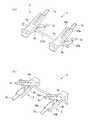
図1(a)、(b)、図2(a)、(b)、図3は、本発明のクリップの第1実施形態を示す図である。なお、図1(a)、(b)はクリップの使用形態を示す斜視図であり、図1(a)、(b)において符号1は2連クリップ、符号2は単位クリップである。また、図2、図3は単位クリップ2の構成を示す図であって、図2(a)は単位クリップ2の開いた状態を示す斜視図、(b)は単位クリップ2の開いた状態を示す側面図、図3は単位クリップ2の分解斜視図である。Hereinafter, the present invention will be described in more detail with reference to the drawings.
1 (a), 1 (b), 2 (a), 2 (b), and 3 are views showing a first embodiment of the clip of the present invention. 1 (a) and 1 (b) are perspective views showing how the clip is used. In FIGS. 1 (a) and 1 (b), reference numeral 1 is a double clip, and
図1(a)、(b)に示すように2連クリップ1は、二つ(一対)の単位クリップ2を、連結軸3によって連結したものである。単位クリップ2は、本実施形態では血管等の管状組織を挟持する医療用のものである。なお、以下の説明においては、単位クリップ2を省略してクリップ2と記すこともある。 As shown in FIGS. 1A and 1B, the double clip 1 is formed by connecting two (a pair of) unit clips 2 by a connecting
クリップ2は、図2(a)、(b)に示すように先端側が開閉可能に構成された一対の保持片4a、4bと、図3に示すようにこれら保持片4a、4b間に取り付けられるトーションバネ(付勢部材)5と、このトーションバネ5を保持片4a、4bに固定するための軸6と、保持片4a、4bの先端部に設けられた挟持片7a、7bと、を有して構成されたものである。なお、本実施形態においては、トーションバネ5を保持片4a、4bに固定するための軸6は、図1に示した連結軸3からなっている。 The
保持片4a(4b)は、ABS樹脂などの合成樹脂によって形成されたもので、図3に示すように後端側に指で摘むための摘み部8a(8b)を有し、中央部に貫通孔(図示せず)を有した一対の軸受け9a、9a(9b、9b)を有し、先端側に前記挟持片7a、7bを保持するための一対のアーム10a、10a(10b、10b)を有して形成されたものである。また、保持片4a(4b)は、側面視した状態で、軸受け9aを中心にしてこの軸受け9aと反対の側に、く字状に折曲させられている。 The holding
一対のアーム10a、10a(10b、10b)は、間隔をあけて保持片4a(4b)の左右に配設されたもので、これらの間に挟持片7a(7b)を保持したものである。これらアーム10a(10b)には、その内面に第1係合部11a(11b)が形成されている。第1係合部11a(11b)は、略半円、つまり半円のなす円弧より短い円弧に対応した半円様の形状の凹部からなるもので、後述するように挟持片7a、7bを閉じ、したがってアーム10a(10b)を閉じた状態で、一対の第1係合部11a、11bによって略円形の凹部を形成するように構成されている。よって、このように挟持片7a、7bを閉じた状態では、一対の第1係合部11a、11bはそれぞれの内周面11cにより、円形の外周の周面の大半を形成するようになっている。 The pair of
挟持片7a、7bは、これらの後端部間を連結し、かつ、該挟持片7a、7bを開く方向に付勢する付勢連結部7cによって連結されたもので、ABS樹脂などの合成樹脂によって一体に形成されたものである。付勢連結部7cは、U字状に形成された薄厚の板材からなるもので、これによって挟持片7a、7bを、一定の開き角度に保持するものである。したがって、挟持片7a、7bが前記の開き角度より小さい角度となるように閉じられると、付勢連結部7cは弾性変形することから、これが元に戻ろうとする弾性復帰力により、挟持片7a、7bを開く方向に付勢するようになっている。 The sandwiching
一対の挟持片7a、7bは、鳥のくちばし状に形成配置されたもので、後端側から先端側に行くに連れて漸次細く、かつ薄くなるように形成されたものである。また、これら挟持片7a、7bの挟持面(保持面)となる内面には、該挟持片7a、7bの長さ方向と直交する方向に延びる突条及び溝からなる凹凸(図示せず)が、滑り止めとして形成されている。これによって挟持片7a、7bは、挟持対象物をより確実に挟持(保持)できるようになっている。また、挟持片7a(7b)には、その両側の外面に、それぞれ前記第1係合部11a(11b)に係合する第2係合部12a(12b)が形成されている。第2係合部12a(12b)は、略半円盤状の凸部(摺動部)からなるもので、その円弧状の外周面12cが、前記第1係合部11a(11b)の内周面11cに摺動する摺動面となっている。 The pair of sandwiching
すなわち、第2係合部12a、12bは、挟持片7a、7bが閉じた際に当接することで円盤状となるように形成されている。したがって、前述したように挟持片7a、7bが閉じた際に円形の外周の周面の大半を形成するようになっている第1係合部11a、11bに対して、第2係合部12a、12bは正逆方向に360°回動可能になっており、これによって一対の挟持片7a、7bは、一対の保持片4a、4bに対して、その開閉方向に360°回動可能になっている。なお、挟持片7a(7b)における第2係合部12a(12b)の中心から先端までの距離は、アーム10a(10b)における第1係合部11a(11b)の中心から後端までの距離より短くなっている。したがって、挟持片7a(7b)はアーム10a(10b)の根本(後端)側に干渉されることなく、アーム10a、10a(10b、10b)間を、その開閉方向に360°回動可能になっている。 That is, the second
また、一対の挟持片7a、7bは、前記したように付勢連結部7cによって開く方向に付勢されていることから、保持片4a、4bのそれぞれのアーム10a、10b間において、第2係合部12a(12b)の外周面(摺動面12c)が第1係合部11a(11b)の内周面(摺動面11c)を押圧するようになっている。したがって、一対の挟持片7a、7bは、付勢連結部7cの付勢力によって一対の保持片4a、4b間に保持されている。また、後述するように保持片4a、4bの先端側のアーム10a、10bを開いた際には、これに追従して挟持片7a、7bも開くようになっており、さらにその状態から閉じた際には、これに追従して閉じるようになっている。 Further, since the pair of sandwiching
なお、保持片4a、4bを開いた状態において、例えば挟持片7a、7bを指で摘んで閉じることにより、前記付勢連結部7cの付勢力による押圧が解除されるため、これら挟持片7a、7bを保持片4a、4bから容易に取り外すことができる。また、逆の操作を行うことにより、挟持片7a、7bを保持片4a、4b間に容易に取り付けることができる。したがって、本実施形態においては、挟持片7a、7bは保持片4a、4bに対して着脱可能に保持されている。 In the state where the holding
また、図1(a)、(b)に示した2連クリップ1において、一対のクリップ(単位クリップ)2、2は、連結軸3(軸6)に対してその周方向に回動不能に設けられており、これによって一対のクリップ2、2は、互いの挟持片7a、7bが同一の方向に向いて配置されている。また、これら一対のクリップ2、2は、連結軸3(軸6)に対してその軸方向に移動することなく固定されて設けられている。これによって一対のクリップ2、2は、その間隔が予め設定された間隔に保持されている。ただし、一対のクリップ2、2については、ある程度の押圧力を加えることでその軸方向に摺動可能になっていてもよく、その場合には、その間隔を任意に設定することが可能になる。 Further, in the double clip 1 shown in FIGS. 1A and 1B, the pair of clips (unit clips) 2 and 2 cannot be rotated in the circumferential direction with respect to the connecting shaft 3 (shaft 6). Thus, the pair of
次に、このような構成の2連クリップ1の使用方法として、血管の断端を縫合する場合について説明する。
まず、図4(a)に示す血管15の断端15a、15aを縫合可能な状態に突き合わせ、その状態で、手前側より一方の単位クリップ2で一方の断端15a側を挟持する。また、同様にして他方の単位クリップ2で他方の断端15a側を挟持する。Next, as a method of using the double clip 1 having such a configuration, a case where a stump of a blood vessel is sutured will be described.
First, the
詳しくは、保持片4a、4bの摘み部8a、8bを指で摘み、その先端側のアーム10a、10bを開く。すると、挟持片7a、7bはアーム10a、10bに追従することにより、これら挟持片7a、7bもその先端側が開く。そして、挟持片7a、7bの先端側で血管15の断端15a側を挟み、その状態で保持片4a、4bの摘み部8a、8bへの押圧を解除する。これにより、保持片4a、4bはトーションバネ5の付勢力によって閉じ、挟持片7a、7bもこれに追従して閉じることにより、血管15を止血した状態に挟持する。このようにすると、一対のクリップ2、2は連結軸3によってその間隔が固定されているので、これらクリップ2、2に血管15の断端15a、15aが挟持されることにより、断端15a、15aもその間隔が固定されたものとなる。 Specifically, the
このようにして二つの単位クリップ2で二つの断端15a側を挟持したら、それぞれの保持片4a、4bの摘み部8a、8b側を、図4(b)に示すように手前側から向こう側、すなわち血管15の奥側に反転させる。すると、手前側に縫合などの処理を行うための空間を確保することができるため、血管15の断端15a、15aの縫合処理が行い易くなる。また、血管15を挟持する挟持片7a、7bについては回動させることなく手前側に残しておくため、血管15にはほとんどねじれが発生しない。したがって、血管15はその張力による戻りがないため、クリップ2、2は挟持片7a、7b、保持片4a、4bの状態を変化させることなく、設定した状態に保持される。なお、クリップ2、2は連結軸3(軸6)に対してその周方向に回動不能になっているので、これら一対のクリップ2、2は、互いの挟持片7a、7bを同一の方向に向けたままに保持される。 When the two cut ends 15a are sandwiched between the two
また、縫合処理が終了した後には、図4(a)に示したように保持片4a、4bの摘み部8a、8bを手前側に戻し、その後、摘み部8a、8bを摘んで挟持片7a、7bを開き、縫合後の血管15から取り外す。
このように本実施形態の2連クリップ1によれば、手前側から挟持片7a、7bによって血管15の断端15a、15aを挟持(保持)し、挟持片7a、7bをその状態にしたままで保持片側4a、4bを向こう側に反転させることができるので、手前側に縫合処理を行うための空間を確保することができ、したがって縫合処理を行い易くすることができる。Further, after the suturing process is completed, as shown in FIG. 4A, the gripping
Thus, according to the double clip 1 of this embodiment, the
また、保持片4a、4bに対して挟持片7a、7bが着脱可能に保持されているので、前記のように医療用として用いる場合に、使用後、血管15などに直接接する挟持片7a、7bのみを交換し、保持片4a、4bについては再使用することが可能になる。したがって、使用に要するコストを十分に低減することができる。 Further, since the holding
なお、前記実施形態では血管15に対して手前側からクリップ2、2の挟持片7a、7bで挟持するようにしたが、図5に示すように血管15の上側から挟持片7a、7bで挟持し、その後保持片4a、4bを向こう側に反転させてもよい。このようにすれば、手前側に挟持片7a、7bも残らないため、縫合処理を行うための空間を手前側により大きく確保することができる。 In the above-described embodiment, the
次に、本発明のクリップの第2実施形態を説明する。この第2実施形態のクリップも、図1に示したように二つ(一対)の単位クリップを連結軸で連結した2連クリップであり、血管等の管状組織を挟持する医療用のものである。また、図6、図7は本実施形態に係る単位クリップ21の構成を示す図であって、図6(a)は単位クリップの閉じた状態を示す斜視図、(b)は単位クリップ2の開いた状態を示す斜視図、図7は単位クリップ2の分解斜視図である。 Next, a second embodiment of the clip of the present invention will be described. The clip of the second embodiment is also a double clip in which two (a pair) unit clips are connected by a connecting shaft as shown in FIG. 1, and is used for medical purposes to hold a tubular tissue such as a blood vessel. . 6 and 7 are views showing the configuration of the
図6(a)、(b)、図7に示すように本実施形態に係る単位クリップ21も、先端側が開閉可能に構成された一対の保持片22a、22bと、図7に示すようにこれら保持片22a、22b間に取り付けられるトーションバネ(付勢部材)5と、このトーションバネ5を保持片22a、22bに固定するための軸6(連結軸3)と、保持片22a、22bの先端部に設けられた挟持片23a、23bと、を有して構成されたものである。 As shown in FIGS. 6A, 6B, and 7, the
すなわち、このクリップ(単位クリップ)21が図2(a)、(b)、図3に示したクリップ2と異なるところは、第1係合部11a、11b、第2係合部12a、12bの構成と、挟持片23a、23bが付勢連結部7cで連結されることなく、それぞれ独立して形成されている点である。なお、本実施形態の挟持片23a、23bは第1実施形態の挟持片7a、7bと異なり、後端側から先端側に行くに連れて漸次細く、かつ薄くなるように形成されておらず、先端側と後端側とが同形状に形成されている。
これら挟持片23a、23bに設けられた、略半円盤状の凸部(摺動部)からなる第2係合部12a(12b)には、本実施形態では図7に示したように凹部からなる第3係合部24a(24b)が形成されている。That is, the clip (unit clip) 21 is different from the
In the present embodiment, the second
第3係合部24a(24b)は、凸部(摺動部)からなる第2係合部12a(12b)の、第1係合部11a(11b)の内周面に対して摺動する外周面(摺動面11c)より内方に形成されたもので、第2係合部12a(12b)の端面形状と略相似状の開口面を有するものである。すなわち、これら第3係合部24a(24b)は、図8に示すようにその略半円状の開口における円弧部分に対応する内周面24cが、一対の第1係合部11a、11bがなす略円と同心円の外周部分となるように形成されており、これによってこの内周面24cが、実質的に本発明における第3係合部として機能するようになっている。 The third
ただし、本実施形態では、図8に示したように内周面24cには波状の凹凸による段差部が形成されており、したがってこの内周面24cがなす平面視形状は、円弧状とはならない。しかし、例えば凹凸の中心線を結んだ曲線、あるいは外側の頂点を結んだ曲線、又は内側の頂点を結んだ曲線が円弧状となり、このような円弧が前記したように第1係合部11a、11bがなす略円と同心円の外周となるように形成されている。そして、これによって本発明においては、波状の凹凸による段差部を有した内周面24cは、第1係合部11a、11bがなす略円と同心円の外周部分になっているものとしている。 However, in the present embodiment, as shown in FIG. 8, the inner
一方、図7に示すように保持片22a、22bのアーム10a、10bに形成された、略半円状の凹部からなる第1係合部11a(11b)には、同じく凹部からなる前記第3係合部24a(24b)の内周面24cに摺動する、突起状の第4係合部25a(25b)が形成されている。第4係合部25a(25b)は、図8に示すように前記内周面24cに相対的に摺動する摺動部となるもので、この内周面24cにおける波状の段差部のうちの凹部に係合し、ここに保持されるように形成配置されたものである。 On the other hand, as shown in FIG. 7, the first engaging
このような構成のもとに挟持片23a(23b)は、保持片22a(22b)のアーム10a、10a(10b、10b)間に回動可能に挟持され、保持されたものとなっている。すなわち、第2係合部12a(12b)の摺動面(湾曲面)12c側が、第1摺動部11a(11b)の内周面(摺動面11c)と第4係合部(摺動部)25a(25b)の摺動面との間に保持され、これによって挟持片23a(23b)は、保持片22a(22b)のアーム10a、10a(10b、10b)間に保持されている。 Under such a configuration, the holding
なお、保持片22a(22b)や挟持片23a(23b)は樹脂からなっているので、多少の弾性変形が可能になっている。したがって、アーム10a、10a(10b、10b)間を広げてここに挟持片23a(23b)を差し入れ、さらに第2係合部12a(12b)を第1係合部11a(11b)内に嵌め込むことにより、第4係合部25a(25b)を第3係合部24a(24b)内に入れ込むことができる。また、このようにして第1係合部11a(11b)に第2係合部12a(12b)を係合させ、さらに第3係合部24a(24b)に第4係合部25a(25b)を係合させると、一旦広げられたアーム10a、10a(10b、10b)間は元の状態に戻り、ここに挟持片23a(23b)が保持されるようになる。 Since the holding
そして、第1実施形態と同様に第2係合部12a(12b)は、その摺動面12cが第1係合部11a(11b)の摺動面11cに摺動するようになる。また、第4係合部25a(25b)も、第3係合部24a(24b)の内周面24cを摺動するようになる。ただし、内周面24cは前記したように波状の凹凸になっているので、第4係合部25a(25b)が凸部分に当接しているときにはその係合状態が安定せず、凹部分に当接しているときに安定する。したがって、第4係合部25a(25b)は内周面24c(第3係合部24a(24b))の凹部のなす部位において安定的に係止し、ここに保持されるようになっている。つまり、第4係合部25a(25b)が内周面24c(第3係合部24a(24b))の凹部のなす部位において係止することにより、保持片22a(22b)に対する挟持片23a(23b)の相対的な回動が規制されるようになっているのである。 As in the first embodiment, the sliding
ここで、第3係合部24a(24b)は閉じた凹部であり、摺動面となる内周面24cはその両端で平面視直線状の内壁面24dに繋がっている。したがって、第4係合部25a(25b)は内周面24cに対して相対的に摺動した際、その両端部においては内壁面24dに規制され、それ以上の回動が不能になっている。よって、本実施形態では、先の第1実施形態とは異なり、挟持片23a(23b)は保持片22a(22b)に対して正逆方向に360°回動することなく、約180°の可動範囲、つまり、図6(a)に示したように保持片22a(22b)のアーム10a(10b)の長さ方向に沿う初期位置に対し、正逆方向にそれぞれ約90°(90°弱)回動するようになっている。 Here, the third
このような構成のクリップ21を一対備えた2連クリップを用いて、血管の断端を縫合する場合にも、図4(a)、(b)に示した第1実施形態とほぼ同様にして行うことができる。
すなわち、図4(a)に示したように血管15の断端15a、15aを縫合可能な状態に突き合わせ、その状態で、例えば手前側より一方の単位クリップ21で一方の断端15a側を挟持し、他方の単位クリップ21で他方の断端15a側を挟持する。Even when a stump of a blood vessel is sutured by using a double clip having a pair of
That is, as shown in FIG. 4 (a), the
このようにして二つの単位クリップ21で二つの断端15a側を挟持したら、それぞれの保持片22a、22bの摘み部8a、8b側を、血管15の奥側に向けて回動させる。ただし、本実施形態では挟持片23a(23b)は、保持片22a(22b)に対して図6(a)に示した初期の状態からは一方向に約90°しか回動できないため、保持片22a(22b)は血管15の上方に留まるようになる。なお、このような挟持片23a(23b)に対する保持片22a(22b)の相対的な位置については、図8に示した第3係合部24a(24b)の内周面24cの凹部と、第4係合部25a(25b)との間の係止によって決まる。したがって、保持片22a(22b)を回動させて移動させる位置については、挟持片23a(23b)に対する相対的な可動範囲において、前記の内周面24cの凹部に対応する位置のうちから、任意の位置を選択することができる。 When the two cut ends 15 a are sandwiched between the two unit clips 21 in this way, the
このようにして保持片22a、22bを回動させると、血管15の手前側に縫合などの処理を行うための空間を確保することができるため、先の第1実施形態と同様に、血管15の断端15a、15aの縫合処理が行い易くなる。また、血管15を挟持する挟持片7a、7bについては回動させることなく手前側に残しておくため、血管15にはほとんどねじれが発生せず、したがってクリップ21、21は設定した状態に保持される。なお、クリップ21、21は連結軸3(軸6)に対してその周方向に回動不能になっているので、これら一対のクリップ21、21も、第1実施形態と同様に互いの挟持片23a、23bを同一の方向に向けたままに保持される。
また、縫合処理が終了した後には、保持片22a、22bの摘み部8a、8bを手前側に戻し、その後、摘み部8a、8bを摘んで挟持片7a、7bを開き、縫合後の血管15から取り外す。When the holding
Further, after the suturing process is completed, the
このように本実施形態の2連クリップにあっても、手前側から挟持片23a、23bによって血管15の断端15a、15aを挟持(保持)し、挟持片23a、23bをその状態にしたままで保持片側22a、22bを回動させることができるので、手前側に縫合処理を行うための空間を確保することができ、したがって縫合処理を行い易くすることができる。
また、保持片22a、22bのアーム10a、10a(10b、10b)間を広げることで挟持片23a、23bを容易に取り外すことができるので、使用後これら挟持片23a、23bのみを交換し、保持片22a、22bについては再使用することができる。As described above, even in the double clip of the present embodiment, the
In addition, the holding
なお、本実施形態においても、図5に示したように血管15に対して上側から挟持片23a、23bで挟持し、その後保持片22a、22bを向こう側に反転させてもよい。
また、この第2実施形態においては、第3係合部24a、24bの内周面24cを波状の凹凸による段差部とし、その凹部において第4係合部25a(25b)を保持固定することで保持片22a(22b)に対する挟持片23a(23b)の相対的な位置を任意の位置に固定できるようにしたが、本発明では内周面24cに凹凸を形成することなく、円孔の内周面と同じ湾曲面に形成してもよい。Also in the present embodiment, as shown in FIG. 5, the
In the second embodiment, the inner
さらに、前記実施形態では、保持片に第1係合部11a、11bを形成し、挟持片に第2係合部12a、12bを形成したが、逆に、保持片に第2係合部12a、12bを形成し、挟持片に第1係合部11a、11bを形成してもよい。
また、前記実施形態では図1に示したように一対の単位クリップを連結軸で連結することにより、2連クリップとして使用するようにしたが、連結軸によって3つ以上の単位クリップを連結することにより、使用するようにしてもよい。また、もちろん1つの単位クリップのみで使用するようにしてもよい。Furthermore, in the said embodiment, although the
In the above embodiment, as shown in FIG. 1, a pair of unit clips are connected by a connecting shaft to be used as a double clip. However, three or more unit clips are connected by a connecting shaft. Therefore, it may be used. Of course, only one unit clip may be used.
さらに、前記実施形態では本発明のクリップを医療用として用いるようにしたが、本発明のクリップは医療用以外にも種々の用途に用いることができる。例えば、一対の樹脂製チューブの端部間をレーザ照射によって溶着する場合にも、本発明の2連クリップを用いることで、その処理を容易にすることができる。同様に、水道管等の金属配管を溶接によって繋げる場合にも、使用することができる。
また、洗濯ばさみとして用いることもでき、さらには、水道管などの配管内に入り込んだものを配管の開口側から抜き出す用途にも、応用することができる。その場合にも、保持片に対して挟持片が回動することを利用することで、その操作が容易になることなどが期待できる。Furthermore, in the said embodiment, although the clip of this invention was used for medical uses, the clip of this invention can be used for various uses besides medical use. For example, also when welding between the edge parts of a pair of resin tubes by laser irradiation, the process can be made easy by using the double clip of this invention. Similarly, it can also be used when connecting metal pipes such as water pipes by welding.
Moreover, it can also be used as a clothespin, and can also be applied to an application for extracting what has entered a pipe such as a water pipe from the opening side of the pipe. Even in that case, it can be expected that the operation becomes easy by utilizing the fact that the holding piece rotates with respect to the holding piece.
1…2連クリップ、2…単位クリップ(クリップ)、3…連結軸、4a、4b…保持片、5…トーションバネ(付勢部材)、6…軸、7a、7b…挟持片、7c…付勢連結部、10a、10b…アーム、11a、11b…第1係合部、11c…摺動面、12a、12b…第2係合部、12c…摺動面、15…血管、15a…断端、21…単位クリップ(クリップ)、22a、22b…保持片、23a、23b…挟持片、24a、24b…第3係合部、24c…摺動面、25a、25b…第4係合部 DESCRIPTION OF SYMBOLS 1 ... Double clip, 2 ... Unit clip (clip), 3 ... Connection shaft, 4a, 4b ... Holding piece, 5 ... Torsion spring (biasing member), 6 ... Shaft, 7a, 7b ... Nipping piece, 7c ... With Force connecting portion, 10a, 10b ... arm, 11a, 11b ... first engaging portion, 11c ... sliding surface, 12a, 12b ... second engaging portion, 12c ... sliding surface, 15 ... blood vessel, 15a ... stump 21 a unit clip (clip) 22 a 22
Claims (8)
Translated fromJapanese前記保持片をその先端側が閉じる方向に付勢する付勢部材と、
前記保持片の先端部に設けられて、前記保持片の先端側の開閉動作に追従して開閉する一対の挟持片と、を有してなり、
前記保持片と前記挟持片とのうちの一方には、その開閉方向に沿う面に、略半円の外周の周面を有する凹部からなる第1係合部が設けられ、
前記保持片と前記挟持片とのうちの他方には、その開閉方向に沿う面に、前記第1係合部の前記周面に沿って摺動する摺動部からなる第2係合部が設けられ、
前記第2係合部が前記第1係合部に係合することにより、前記一対の挟持片は、該一対の挟持片が開閉する側となる先端部より後端側で前記一対の保持片に対して取り付けられており、
前記第1係合部は、前記一対の保持片の先端側と前記一対の挟持片の先端部とが閉じた状態で、一対の前記凹部が略円の周面を形成するよう構成され、
前記第2係合部が、前記一対の保持片の先端側と前記一対の挟持片の先端部とが閉じた状態で、前記第1係合部の凹部のなす略円の周面を摺動することにより、前記一対の挟持片は前記一対の保持片に対して、該一対の保持片の開閉方向に沿う方向に相対的に回動可能になっていることを特徴とするクリップ。A pair of holding pieces configured to be openable and closable at the distal end side;
An urging member for urging the holding piece in a direction in which a tip end side thereof is closed;
A pair of clamping pieces that are provided at the tip of the holding piece and open and close following the opening and closing operation on the tip side of the holding piece,
One of the holding piece and the sandwiching piece is provided with a first engaging portion formed of a concave portion having a substantially semicircular outer peripheral surface on a surface along the opening and closing direction thereof.
The other of the holding piece and the holding piece has a second engaging portion formed of a sliding portion that slides along the peripheral surface of the first engaging portion on a surface along the opening / closing direction thereof. Provided,
When the second engaging portion engages with the first engaging portion, the pair of holding pieces are arranged on the rear end side of the pair of holding pieces on the rear end side that is the side where the pair of holding pieces open and close. Attached to the
The first engaging portion is configured such that the pair of concave portions forms a substantially circular peripheral surface in a state where the distal end sides of the pair of holding pieces and the distal end portions of the pair of holding pieces are closed.
The second engagement portion slides on a substantially circular circumferential surface formed by the recess of the first engagement portion in a state where the distal end sides of the pair of holding pieces and the distal end portions of the pair of holding pieces are closed. clipby said pair of clampingpieces, characterized in that with respect tothe pair of holdingpieces,has become relatively rotatablein a direction along the opening and closing direction of the pair of holding pieces.
前記第1係合部には、前記第3係合部の凹部のなす周面を摺動する摺動部からなる第4係合部が設けられていることを特徴とする請求項1記載のクリップ。The second engaging portion has a substantially outer circumference that is concentric with the substantially circular circle formed by the first engaging portion, inward of the sliding surface of the sliding portion that slides on the circumferential surface of the first engaging portion. A third engagement portion comprising a recess having a peripheral surface is provided;
Wherein the first engagement portion, of claim1, wherein the fourth engagement portion comprising a sliding portion that slides formed peripheral surface of the concave portion of the third engaging portion is provided clip.
Priority Applications (1)
| Application Number | Priority Date | Filing Date | Title |
|---|---|---|---|
| JP2008313056AJP5401088B2 (en) | 2008-12-09 | 2008-12-09 | clip |
Applications Claiming Priority (1)
| Application Number | Priority Date | Filing Date | Title |
|---|---|---|---|
| JP2008313056AJP5401088B2 (en) | 2008-12-09 | 2008-12-09 | clip |
Publications (2)
| Publication Number | Publication Date |
|---|---|
| JP2010136749A JP2010136749A (en) | 2010-06-24 |
| JP5401088B2true JP5401088B2 (en) | 2014-01-29 |
Family
ID=42347394
Family Applications (1)
| Application Number | Title | Priority Date | Filing Date |
|---|---|---|---|
| JP2008313056AExpired - Fee RelatedJP5401088B2 (en) | 2008-12-09 | 2008-12-09 | clip |
Country Status (1)
| Country | Link |
|---|---|
| JP (1) | JP5401088B2 (en) |
Families Citing this family (4)
| Publication number | Priority date | Publication date | Assignee | Title |
|---|---|---|---|---|
| RU2485908C2 (en)* | 2010-12-07 | 2013-06-27 | Компания с ограниченной ответственностью Глобитек 2000 | Method of creating hemostasis with possibility of blood flow recovery in tubular elastic structures of organism and devices for its realisation |
| WO2014065232A1 (en)* | 2012-10-23 | 2014-05-01 | 学校法人久留米大学 | Blood vessel clamp device and blood vessel anastomosis method using same |
| CN109646072B (en)* | 2019-01-08 | 2024-02-06 | 成都迪康中科生物医学材料有限公司 | Hemostatic clamp |
| CN213781553U (en)* | 2020-07-03 | 2021-07-23 | 深圳市伏荣科技开发有限公司 | Clamp and clamp type tuning device |
Family Cites Families (9)
| Publication number | Priority date | Publication date | Assignee | Title |
|---|---|---|---|---|
| JPS5344311Y2 (en)* | 1976-07-16 | 1978-10-24 | ||
| JPS5797510U (en)* | 1980-12-05 | 1982-06-15 | ||
| JPS58152910U (en)* | 1982-04-05 | 1983-10-13 | 有限会社マルイ医科 | aneurysm clip forceps |
| US4827930A (en)* | 1982-06-28 | 1989-05-09 | Codman & Shurtleff, Inc. | Reinforcing closer for aneurysm clip |
| US4932955A (en)* | 1984-06-29 | 1990-06-12 | Baxter International Inc. | Clip |
| JPH0340254Y2 (en)* | 1985-09-11 | 1991-08-23 | ||
| JPS6392344A (en)* | 1986-10-08 | 1988-04-22 | 瑞穂医科工業株式会社 | Blood vessel grip |
| DE19935418C5 (en)* | 1999-07-28 | 2013-08-29 | Aesculap Ag | Surgical clip |
| JP2005177053A (en)* | 2003-12-18 | 2005-07-07 | Mizuho Co Ltd | Forceps for clip |
- 2008
- 2008-12-09JPJP2008313056Apatent/JP5401088B2/ennot_activeExpired - Fee Related
Also Published As
| Publication number | Publication date |
|---|---|
| JP2010136749A (en) | 2010-06-24 |
Similar Documents
| Publication | Publication Date | Title |
|---|---|---|
| JP5401088B2 (en) | clip | |
| TWI391119B (en) | Integrated double clips applier cvith division device for clamping clips | |
| US4165745A (en) | Surgical manipulator | |
| US4950281A (en) | Everting forceps | |
| JP3157486U (en) | Surgical clip | |
| JP4972224B1 (en) | Gripper, needle holder and attachment | |
| US10945736B2 (en) | Fixing device for blood vessel suturing | |
| JP2019208953A (en) | Hemostatic device | |
| JP6250847B1 (en) | Tube holder | |
| CN109864772A (en) | Microsurgical instruments and improvements in handles | |
| JPWO2018235401A1 (en) | Clip treatment tool | |
| US20200323329A1 (en) | Applicator for makeup product | |
| WO2021172291A1 (en) | Grasping forceps, forceps-feeding tool, and forceps-collecting tool | |
| US12201316B2 (en) | Micro needle holder capable of cutting sutures | |
| JP6388452B2 (en) | Multi-clamp for blood vessels | |
| JP2021522891A (en) | Surgical instruments and related methods | |
| JP5276235B1 (en) | Double clip | |
| JP3133498U (en) | Medical clip | |
| WO2021235219A1 (en) | Pharmaceutical agent applicator, kit for application of pharmaceutical agent, and pressing tool for pharmaceutical agent applicator | |
| JPWO2018230613A1 (en) | Molding jig for dysphonia treatment device and method for bending front piece of dysphonia treatment device | |
| JP6247335B2 (en) | Sewing clip | |
| JP2019126637A (en) | forceps | |
| JP5103609B2 (en) | Needle holder | |
| JP6850411B2 (en) | Needle holder | |
| JP3228189U (en) | Tongs |
Legal Events
| Date | Code | Title | Description |
|---|---|---|---|
| A621 | Written request for application examination | Free format text:JAPANESE INTERMEDIATE CODE: A621 Effective date:20111102 | |
| A131 | Notification of reasons for refusal | Free format text:JAPANESE INTERMEDIATE CODE: A131 Effective date:20130507 | |
| A521 | Request for written amendment filed | Free format text:JAPANESE INTERMEDIATE CODE: A523 Effective date:20130612 | |
| TRDD | Decision of grant or rejection written | ||
| A01 | Written decision to grant a patent or to grant a registration (utility model) | Free format text:JAPANESE INTERMEDIATE CODE: A01 Effective date:20131001 | |
| A61 | First payment of annual fees (during grant procedure) | Free format text:JAPANESE INTERMEDIATE CODE: A61 Effective date:20131028 | |
| R150 | Certificate of patent or registration of utility model | Free format text:JAPANESE INTERMEDIATE CODE: R150 Ref document number:5401088 Country of ref document:JP Free format text:JAPANESE INTERMEDIATE CODE: R150 | |
| R250 | Receipt of annual fees | Free format text:JAPANESE INTERMEDIATE CODE: R250 | |
| R250 | Receipt of annual fees | Free format text:JAPANESE INTERMEDIATE CODE: R250 | |
| R250 | Receipt of annual fees | Free format text:JAPANESE INTERMEDIATE CODE: R250 | |
| R250 | Receipt of annual fees | Free format text:JAPANESE INTERMEDIATE CODE: R250 | |
| R250 | Receipt of annual fees | Free format text:JAPANESE INTERMEDIATE CODE: R250 | |
| R250 | Receipt of annual fees | Free format text:JAPANESE INTERMEDIATE CODE: R250 | |
| R250 | Receipt of annual fees | Free format text:JAPANESE INTERMEDIATE CODE: R250 | |
| LAPS | Cancellation because of no payment of annual fees |