Movatterモバイル変換


[0]ホーム

URL:


JP5399742B2 - Auxiliary tool and endoscope system using the same - Google Patents

Auxiliary tool and endoscope system using the same
Download PDF

Info

Publication number
JP5399742B2
JP5399742B2JP2009049372AJP2009049372AJP5399742B2JP 5399742 B2JP5399742 B2JP 5399742B2JP 2009049372 AJP2009049372 AJP 2009049372AJP 2009049372 AJP2009049372 AJP 2009049372AJP 5399742 B2JP5399742 B2JP 5399742B2
Authority
JP
Japan
Prior art keywords
endoscope
distal end
illumination
auxiliary
window
Prior art date
Legal status (The legal status is an assumption and is not a legal conclusion. Google has not performed a legal analysis and makes no representation as to the accuracy of the status listed.)
Expired - Fee Related
Application number
JP2009049372A
Other languages
Japanese (ja)
Other versions
JP2010200954A (en
Inventor
雄一 鳥居
治彦 新井
健彦 古賀
利幸 池田
正也 井上
正広 関
朝春 西野
勝蔵 井山
Current Assignee (The listed assignees may be inaccurate. Google has not performed a legal analysis and makes no representation or warranty as to the accuracy of the list.)
Fujifilm Corp
Original Assignee
Fujifilm Corp
Priority date (The priority date is an assumption and is not a legal conclusion. Google has not performed a legal analysis and makes no representation as to the accuracy of the date listed.)
Filing date
Publication date
Application filed by Fujifilm CorpfiledCriticalFujifilm Corp
Priority to JP2009049372ApriorityCriticalpatent/JP5399742B2/en
Priority to EP11000559.2Aprioritypatent/EP2340758B1/en
Priority to EP13156521.0Aprioritypatent/EP2596743B1/en
Priority to EP09252646.6Aprioritypatent/EP2189106B1/en
Priority to US12/621,234prioritypatent/US20100125165A1/en
Publication of JP2010200954ApublicationCriticalpatent/JP2010200954A/en
Application grantedgrantedCritical
Publication of JP5399742B2publicationCriticalpatent/JP5399742B2/en
Expired - Fee Relatedlegal-statusCriticalCurrent
Anticipated expirationlegal-statusCritical

Links

Images

Classifications

Landscapes

Description

Translated fromJapanese

本発明は、経鼻内視鏡と組み合わせて使用される補助具、及びそれを用いる内視鏡システムに関するものである。  The present invention relates to an auxiliary tool used in combination with a transnasal endoscope, and an endoscope system using the same.

近年、体内に挿入する挿入部を経口内視鏡よりも細径にした経鼻内視鏡が知られている(特許文献1、特許文献2)。この内視鏡を使用する経鼻内視鏡検査は、挿入部が舌のつけ根を通らず、のどにも触れないので、経口内視鏡検査に比べ、検査時の吐き気・不快感が大幅に軽減できて被検者の苦痛や負担を軽減することができると共に、経口内視鏡検査に比べ麻酔薬も少量で良く、また、被検者は検査中に術者等と会話をすることができ、口呼吸も可能となる等の利点があるため、需要が増えている。  In recent years, transnasal endoscopes are known in which an insertion portion to be inserted into the body has a diameter smaller than that of an oral endoscope (Patent Documents 1 and 2). Nasal endoscopy using this endoscope does not pass through the base of the tongue and does not touch the throat, so nausea and discomfort at the time of the examination are significantly higher than oral endoscopy The pain and burden on the subject can be reduced, and a smaller amount of anesthetic can be used compared to the oral endoscopy, and the subject may have a conversation with the operator during the examination. Demand is increasing due to the advantages of being able to breathe through the mouth.

経鼻内視鏡には、経口内視鏡と同じに、体内に挿入される挿入部の先端部に観察光学系と照明光学系とが内蔵されており、照明光学系で被写体を照明し、照明された被写体の画像情報を観察光学系で映像信号として取り出し、モニタ等によりその画像を表示する。挿入部には、先端部から基端部へと貫通する内部空間に、鉗子管路(吸引管路を兼ねる)、送気・送水用管路、及びライトガイド等が収容されている。  A transnasal endoscope, like an oral endoscope, has an observation optical system and an illumination optical system built into the distal end of an insertion part that is inserted into the body. The illumination optical system illuminates a subject, Image information of the illuminated subject is extracted as a video signal by the observation optical system, and the image is displayed on a monitor or the like. The insertion portion accommodates a forceps conduit (also serving as a suction conduit), an air / water supply conduit, a light guide, and the like in an internal space penetrating from the distal end portion to the proximal end portion.

ライトガイドは、光が入射する入射端と光を出射する出射端とを有し、光を光源装置から先端部へと導く。出射端から出射される光は、照明レンズを通して先端部の先端面に設けた照明窓から被写体に向けて照射される。鉗子管路は、一端が先端面に設けた鉗子出口に、また他端が基端部に設けた鉗子入口にそれぞれ繋がっており、鉗子入口から鉗子出口へと処置具の挿入をガイドする。送気・送水用管路は、先端面に設けた送気・送水ノズルに繋がっており、基端部に設けた手元操作部のボタン操作により観察光学系の先端面(観察窓)や体腔内に空気や水を送る。  The light guide has an incident end where light enters and an output end where light is emitted, and guides the light from the light source device to the distal end. The light emitted from the emission end is irradiated toward the subject from the illumination window provided on the distal end surface of the distal end portion through the illumination lens. One end of the forceps conduit is connected to a forceps outlet provided on the distal end surface, and the other end is connected to a forceps inlet provided on the proximal end portion, and guides insertion of the treatment tool from the forceps inlet to the forceps outlet. The air supply / water supply conduit is connected to the air supply / water supply nozzle provided on the distal end surface, and the distal end surface (observation window) or body cavity of the observation optical system is operated by operating the button on the proximal operation portion provided on the proximal end. Send air or water to the.

特開2006−68030号公報JP 2006-68030 A特開2007−61377号公報JP 2007-61377 A

内視鏡の挿入部の先端面には、観察窓や照明窓等と並んで鉗子出口が設けられている。したがって、鉗子出口から鉗子が突出すると、鉗子出口を挟んで照明窓とは逆側に鉗子の影が出やすい。このようになると、患部が鉗子の影になって少し薄暗くなって観察し難い。特に鉗子の先端に設けた鉗子片が開くと、影の範囲が大きくなり、患部が一層薄暗くなって観察が不明瞭になってしまう。  A forceps outlet is provided on the distal end surface of the insertion portion of the endoscope along with an observation window and an illumination window. Therefore, when the forceps protrude from the forceps outlet, a shadow of the forceps tends to appear on the opposite side of the illumination window across the forceps outlet. When this happens, the affected area becomes a shadow of forceps and becomes a little dim and difficult to observe. In particular, when the forceps piece provided at the tip of the forceps is opened, the range of the shadow becomes large, the affected area becomes further dim, and the observation becomes unclear.

本発明はこのような事情に鑑みてなされたもので、鉗子の影を無くすると共に、鉗子片が開いた状態であっても、その前方にある患部を明るく照明して、良好な内視鏡観察下に鉗子処置を行うことができる補助具、及び内視鏡システムを提供することを目的とする。  The present invention has been made in view of such circumstances, and eliminates the shadow of the forceps and brightly illuminates the affected area in front of the forceps piece even when the forceps piece is open. An object is to provide an auxiliary tool capable of performing a forceps treatment under observation and an endoscope system.

本発明の内視鏡システムの一形態では、一方の外鼻孔に挿入される挿入部と、挿入部の先端部の先端面に設けられ観察窓と、観察窓を挟む両側に設けられる一対の照明窓と、先端面に設けられた鉗子出口から基端部に向けた内部空間に有する鉗子管路と、を含む内視鏡と;他方の外鼻孔に挿入される挿入部と、その挿入部の先端面に設けられ、一対の照明窓から放たれる照明光を補助する補助照明光を照射する補助用照明窓と、を有し、内視鏡と組み合わせて使用される補助具と;補助具及び内視鏡との挿入部の先端部同士を先端面が同じ方向に向くように着脱自在に固定するための固定手段と;を備え、固定手段は、内視鏡の先端面の外周のうちの鉗子出口を挟んで一対の照明窓のうちのいずれか一方の照明窓とは逆側の外周に補助具の先端面を固定するIn one form of the endoscope system of the present invention, an insertion portion to be inserted into onenostril, and a distal end observation windowthat is provided on the front end face of theinterpolation join theclub, the pair provided on both sides of the observation window an illumination window, a forceps conduithaving a forceps outlet providedabove the end facein the internal space towards the proximalend, the endoscopecomprising: an insertion portion to be inserted into the nostrils of theother hand, the insertion provided on a distal end surface of the partshas an auxiliary illumination windowfor irradiating the auxiliary illumination light you assist emitted illumination light froma pair of illumination windows,and a aid that is used in conjunction withendoscope; and fixing means for the distal end surface of the distal ends of the insertion portion of theauxiliary Jogu及beauty endoscope is detachably fixed so as to face in the same direction; comprisinga fixedunit, theendoscope theone of the illumination windowof the pair of illumination windows across theforceps child outletof the outer periphery of the distal end surface of the opposite sideouter peripheryauxiliary toolThe end face isfixed.

発明の補助具の一形態では、一方の外鼻孔から体腔内に挿入される内視鏡用挿入部、先端部の先端面に設けられている観察窓、先端面に設けられ観察窓の観察範囲を照明する照明光を放つ照明窓、先端面に設けられる鉗子出口、及び先端部に有し基端部に設けた湾曲操作部の操作に応じて先端部を湾曲させる湾曲部を有する内視鏡と組み合わせて使用されるとともに、他方の外鼻孔から体腔内に挿入される補助用挿入部と、補助用挿入部の先端部に有し、内視鏡の湾曲部の湾曲に従動して湾曲する補助用湾曲部と、補助用挿入部の先端部の先端面に設けられ、内視鏡の照明窓から照射される照明光を補助する補助照明光を照射する補助用照明窓と、補助用湾曲部を内視鏡の湾曲部に対して並列的に密着させて、補助用挿入部の先端部を内視鏡用挿入部の先端部に、内視鏡用挿入部の先端面の外周のうちの鉗子出口を挟んで照明窓とは逆側の外周で、且つ双方の先端面が同じ向きに、かつ軸方向で略同じ位置になるように、着脱自在に固定する固定手段と、を備える。In one embodiment of the auxiliary tool ofthe present invention, the endoscope insertionportion, an observation window provided in the front end surface of theaboveend, an observation window provided at a distal end surface which is inserted into a body cavity from one nostril havingillumination window for emitting illumination light for illuminating the observationrange, a forceps outlet providedabove the end face,and thebending portion for bending the distal portion according to a bending operation portion of the operation provided in the base end portion has a tip portion together are used in combination with an endoscopeincludes a auxiliary insertion portion to be inserted into a nostril oret body lumenotherhand, the tip portion of the auxiliary insertion portion, the bending of the bending portion of the endoscope auxiliary irradiatingthe auxiliary curved portion which is curved and driven, provided on the distal end surface of the distal end portion for insertion portionauxiliary, auxiliary illumination light to assist the illumination light emitted from the illumination window of theendoscopeto an illuminationwindow, and parallel contact is allowed with respect to the bending portion of the endoscope auxiliary bending unit, the endoscope tip portion of the auxiliary insertion portion The outer periphery of the distal end surface of the insertion portion for the endoscope has the outer periphery opposite to the illumination window across the forceps outlet, and both distal end surfaces are in the same direction and in the axial direction. And a fixing means for detachably fixing so as to be in substantially the same position.

本件開示の内視鏡システム、及び補助具は、内視鏡の照明光により生じる鉗子の影を消すことができる。The endoscope system of the present disclosure, and aid,the shadow of the forceps caused by the illumination light ofthe endoscope canvanishing Succoth.

本発明の経鼻内視鏡と補助具からなる内視鏡システムの使用状態を示す説明図である。It is explanatory drawing which shows the use condition of the endoscope system which consists of a transnasal endoscope of this invention, and an auxiliary tool.内視鏡の挿入部を示す断面図である。It is sectional drawing which shows the insertion part of an endoscope.内視鏡の挿入部の先端面を示す説明図である。It is explanatory drawing which shows the front end surface of the insertion part of an endoscope.内視鏡の先端硬質部の内部を示す断面図である。It is sectional drawing which shows the inside of the front-end | tip hard part of an endoscope.補助具の挿入部を示す断面図である。It is sectional drawing which shows the insertion part of an auxiliary tool.補助具の先端部の内部を示す断面図である。It is sectional drawing which shows the inside of the front-end | tip part of an auxiliary tool.内視鏡と補助具との先端部を固定した状態を示す正面図である。It is a front view which shows the state which fixed the front-end | tip part of an endoscope and an auxiliary tool.内視鏡と補助具との先端部を固定した状態を示す斜視図である。It is a perspective view which shows the state which fixed the front-end | tip part of an endoscope and an auxiliary tool.モニタに映し出される鉗子と、その影とを示す説明図である。It is explanatory drawing which shows the forceps projected on a monitor, and its shadow.鉗子が出入り範囲の軸と、補助具の照明光の光束との関係を示す斜視図である。It is a perspective view which shows the relationship between the axis | shaft of the forceps entry / exit range, and the light beam of the illumination light of an auxiliary tool.本発明の内視鏡システムの電気的接続形態の概略を示す説明図である。It is explanatory drawing which shows the outline of the electrical connection form of the endoscope system of this invention.本発明の内視鏡システムの物理的接続形態の概略を示す説明図である。It is explanatory drawing which shows the outline of the physical connection form of the endoscope system of this invention.光源装置を示す斜視図である。It is a perspective view which shows a light source device.本発明の内視鏡システムを使って内視鏡検査又は処置・治療を行う手順を示すフローチャートである。It is a flowchart which shows the procedure which performs endoscopy or treatment and treatment using the endoscope system of the present invention.内視鏡及び補助具を外鼻孔から中鼻道を通して後鼻孔・食道に挿入する状態を示す説明図である。It is explanatory drawing which shows the state which inserts an endoscope and an auxiliary tool into a posterior nostril and an esophagus through a middle nasal passage from an outer nostril.内視鏡に設けた2つの照明窓に対する二箇所の影消し位置のうちのいずれか一方に取り付けられる補助具の別の実施形態を示す説明図である。It is explanatory drawing which shows another embodiment of the auxiliary tool attached to either one of the two shadowing positions with respect to the two illumination windows provided in the endoscope.2つの照明窓を設けた補助具の他の実施形態を示す説明図である。It is explanatory drawing which shows other embodiment of the auxiliary tool which provided two illumination windows.図17で説明した補助具の2つの照明手段の配光特性を示す説明図である。It is explanatory drawing which shows the light distribution characteristic of the two illumination means of the auxiliary tool demonstrated in FIG.内視鏡に設けた2つの照明窓に対する二箇所の影消し位置の全部に照明窓を配する補助具のその他の実施形態を示す説明図である。It is explanatory drawing which shows other embodiment of the auxiliary tool which distribute | arranges an illumination window to all the two shadowing positions with respect to the two illumination windows provided in the endoscope.

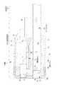
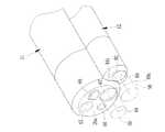
内視鏡システム10は、図1に示すように、経鼻内視鏡(以下、「内視鏡」)11、補助具12、光源装置13、プロセッサ装置14、及びモニタ15等を備えている。内視鏡11は、一方の外鼻孔に挿入される挿入部16を有する。挿入部16の基端部に接続される把持部22aには、手元操作部17が取り付けられ、手元操作部17には、光源装置13、及びプロセッサ装置14にそれぞれ接続されるユニバーサルコネクタ18がユニバーサルケーブル18aの先端に設けられている。この内視鏡11の挿入部16には、先端部から把持部22aへと貫通する内部空間に鉗子管路が設けられている。鉗子管路は、一端が先端部に設けた鉗子出口に、また他端は把持部22aに設けた鉗子入口19にそれぞれ接続されている。なお、鉗子入口19は、手元操作部17に設けてもよい。把持部22aと手元操作部17とで操作部本体を構成する。As shown in FIG. 1, the endoscope system 10 includes a nasal endoscope (hereinafter “endoscope”) 11, anauxiliary tool 12, alight source device 13, aprocessor device 14, amonitor 15, and the like. .Theendoscope 11includes aninsertion portion 16 to be inserted into one nostril. Ahand operating part 17 is attached to the grip part 22a connected to the proximal end of theinsertion part 16, and auniversal connector 18 connected to thelight source device 13 and theprocessor device 14 is universally connected to thehand operating part 17, respectively. It is provided at the tip of the cable 18a. Theinsertion portion 16 of theendoscope 11 is provided with a forceps conduit in an internal space penetrating from the distal end portion to the grasping portion 22a. One end of the forceps conduit is connected to a forceps outlet provided at the distal end, and the other end is connected to aforceps inlet 19 provided at the grip portion 22a. Theforceps inlet 19 may be provided in thehand operation unit 17. The gripping portion 22a and thehand operation portion 17 constitute an operation portion main body.

手元操作部18には、2つの湾曲操作ノブ22の他に、送気・送水ボタン23、及び吸引ボタン24等が設けられている。鉗子入口21には、鉗子栓25が着脱自在に取り付けられており、鉗子栓25は、処置具によって押し開かれるスリット又は小孔を形成した弾性を有する栓部をもっており、鉗子管路を通じて体内汚液等が鉗子入口21から外部に噴出しないように鉗子入口21を部分的にシールする。  In addition to the twobending operation knobs 22, thehand operation unit 18 is provided with an air /water supply button 23, asuction button 24, and the like. Aforceps plug 25 is detachably attached to theforceps inlet 21, and theforceps plug 25 has an elastic plug portion formed with a slit or a small hole that is pushed and opened by the treatment instrument, and is contaminated through the forceps conduit. Theforceps inlet 21 is partially sealed so that liquid or the like does not eject from theforceps inlet 21 to the outside.

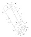
内視鏡11の挿入部16は、周知のように、先端硬質部26、湾曲部27、及び軟性部28とで構成されている。湾曲部27の前後には、補助具12の挿入部29の先端部を固定するための円弧状の磁石体30,31が一対設けられている。なお、先端硬質部26と湾曲部27とが本発明の内視鏡11の挿入部16の先端部20を構成する。  As is well known, theinsertion portion 16 of theendoscope 11 includes a distal endhard portion 26, abending portion 27, and aflexible portion 28. Before and after thebending portion 27, a pair of arc-shaped magnet bodies 30 and 31 for fixing the distal end portion of theinsertion portion 29 of theauxiliary tool 12 are provided. Note that the distal endhard portion 26 and thecurved portion 27 constitute thedistal end portion 20 of theinsertion portion 16 of theendoscope 11 of the present invention.

内視鏡の先端硬質部26には、硬質な金属材料等で形成された先端部本体の内部に観察光学系、撮像素子や照明光学系等が内蔵されている。ユニバーサルコネクタ19は、ライトガイド用コネクタ(LG用コネクタ)32と、これから延設されたコード33の先端に設けたビデオ用コネクタ(電気用コネクタ)34とから構成されている。電気用コネクタ34がプロセッサ装置14に設けた電気用ソケット35に、また、LG用コネクタ32が光源装置13に設けたLG用ソケット36にそれぞれ接続される。  The harddistal end portion 26 of the endoscope incorporates an observation optical system, an image sensor, an illumination optical system, and the like inside a distal end portion main body formed of a hard metal material or the like. Theuniversal connector 19 includes a light guide connector (LG connector) 32 and a video connector (electrical connector) 34 provided at the tip of acord 33 extending therefrom. Theelectrical connector 34 is connected to anelectrical socket 35 provided in theprocessor device 14, and the LGconnector 32 is connected to an LGsocket 36 provided in thelight source device 13.

プロセッサ装置14には、電源回路、撮像素子から得られる撮像信号を画像処理してコンポジット信号やRGBコンポーネント信号にエンコードするための画像処理回路等が設けられている。光源装置13には、光源ランプが内蔵されており、その光は、手元操作部18を通って挿入部16の内部空間に収容したライトガイド(ファイバーバンドル)によって把持部17から先端部20へと導かれて照明光学系に入射する。  Theprocessor device 14 is provided with a power supply circuit, an image processing circuit for performing image processing on an image pickup signal obtained from the image pickup device and encoding it into a composite signal or an RGB component signal. Thelight source device 13 has a built-in light source lamp, and the light passes from thehand operating unit 18 to thedistal end 20 through the light guide (fiber bundle) accommodated in the internal space of theinsertion unit 16. It is guided and enters the illumination optical system.

軟性部28は、手元操作部18と湾曲部27との間を細径で長尺状に繋ぐ部分であり、可撓性を有している。湾曲部27は、手元操作部18に設けた湾曲操作ノブ22の操作に連動して挿入部16の内部空間に収容したアングルワイヤが押し引きされて湾曲動作する。これにより、先端硬質部26の先端面20aを体腔内の所望の方向に向けて観察部位を観察する。観察部位は、照明光学系から放たれる光により照明され、その反射光を、観察光学系を介して撮像素子で撮像し、画像処理回路を介してモニタ15に表示する。  Theflexible portion 28 is a portion that connects thehand operating portion 18 and thebending portion 27 in a narrow shape with a long diameter, and has flexibility. Thebending portion 27 performs a bending operation by pushing and pulling the angle wire accommodated in the internal space of theinsertion portion 16 in conjunction with the operation of thebending operation knob 22 provided in thehand operation portion 18. As a result, the observation site is observed with thedistal end surface 20a of the distalrigid portion 26 directed in a desired direction within the body cavity. The observation site is illuminated with light emitted from the illumination optical system, and the reflected light is imaged by the imaging device via the observation optical system and displayed on themonitor 15 via the image processing circuit.

補助具12は、内視鏡11と組み合わせて使用されるものであり、挿入部29、把持部40、及び補助LG用コネクタ41を備えている。挿入部29は、内視鏡11の挿入部16が挿入されていない他方の外鼻孔に挿入される。把持部40は、挿入部29の後端部29aに取り付けられており、グリップし易いように太径になっている。補助LG用コネクタ41は、把持部40から延設されたコード42の先端に設けられ、光源装置13の補助LG用ソケット43に着脱自在に接続される。補助具12の挿入部29は、先端から順に先端基部44、湾曲部45、及び可撓管部46とで構成されている。  Theauxiliary tool 12 is used in combination with theendoscope 11, and includes aninsertion portion 29, a grippingportion 40, and anauxiliary LG connector 41. Theinsertion portion 29 is inserted into the other outer nostril where theinsertion portion 16 of theendoscope 11 is not inserted. Thegrip portion 40 is attached to therear end portion 29a of theinsertion portion 29 and has a large diameter so that it can be easily gripped. Theauxiliary LG connector 41 is provided at the tip of acord 42 extending from thegrip portion 40 and is detachably connected to theauxiliary LG socket 43 of thelight source device 13. Theinsertion portion 29 of the assistingtool 12 includes a distalend base portion 44, a bendingportion 45, and aflexible tube portion 46 in order from the distal end.

補助具12の湾曲部45には、挿入方向に対する前後に、円弧状の磁石体48,49が一対設けられている。これら一対の磁石体48,49は、挿入経路のうちの後鼻道から食道までの範囲に挿入されたときに、内視鏡11の一対の磁石体30,31に磁着する。これにより、補助具12の湾曲部45は、内視鏡11の湾曲部27の湾曲に従動して湾曲し、補助具12の先端部50の先端面44aは、内視鏡11の先端面20aと同じ向きになる。  A pair of arc-shapedmagnet bodies 48 and 49 are provided on the bendingportion 45 of theauxiliary tool 12 before and after the insertion direction. The pair ofmagnet bodies 48 and 49 are magnetically attached to the pair ofmagnet bodies 30 and 31 of theendoscope 11 when inserted in a range from the posterior nasal passage to the esophagus in the insertion path. Thereby, the bendingportion 45 of theauxiliary tool 12 is bent following the bending of the bendingportion 27 of theendoscope 11, and thedistal end surface 44 a of thedistal end portion 50 of theauxiliary instrument 12 is bent. It becomes the same direction as.

補助具12の先端基部44は、硬質な材料で形成されている。湾曲部45は、内視鏡11の湾曲部27と一緒に湾曲する柔軟な部分である。可撓管部46は、挿入部29の後端部29aと湾曲部45との間を細径で長尺状に繋ぐ部分であり、可撓性を有している。なお、先端基部44と湾曲部45とが本発明の補助具12の先端部50を構成する。  The distalend base portion 44 of theauxiliary tool 12 is formed of a hard material. The bendingportion 45 is a flexible portion that bends together with the bendingportion 27 of theendoscope 11. Theflexible tube portion 46 is a portion that connects therear end portion 29a of theinsertion portion 29 and the bendingportion 45 in a long shape with a small diameter, and has flexibility. Note that the distalend base portion 44 and thecurved portion 45 constitute thedistal end portion 50 of theauxiliary tool 12 of the present invention.

補助具12の挿入部29には、先端部50から後端部29aへと貫通する内部空間にライトガイドが設けられている。このライトガイドは、挿入部29の先端面44aに設けた照明窓の奧に配した照明光学系に光源装置13から得られる照明光を伝送する。なお、挿入部16,29は、どちらも外鼻孔から後鼻孔、食道と経て胃や十二指腸等に挿入されるために、細径のフレキシブルな管状に形成されており、略同じ長さになっている。また、鼻孔への挿入テストで内視鏡11の挿入部16を片方の鼻孔に挿入するのが無理であると判断される場合もあるので、補助具12の挿入部29は、内視鏡11の挿入部16よりも細径にされている。なお、略同じ径にしてもよい。  Theinsertion portion 29 of theauxiliary tool 12 is provided with a light guide in an internal space penetrating from thedistal end portion 50 to therear end portion 29a. This light guide transmits the illumination light obtained from thelight source device 13 to the illumination optical system disposed in the edge of the illumination window provided on thedistal end surface 44 a of theinsertion portion 29. Theinsertion portions 16 and 29 are both formed into a thin flexible tube so that theinsertion portions 16 and 29 are inserted into the stomach, duodenum and the like through the outer nostril, the posterior nostril, and the esophagus. Yes. In addition, since it may be determined that it is impossible to insert theinsertion portion 16 of theendoscope 11 into one of the nostrils in an insertion test into the nostril, theinsertion portion 29 of theauxiliary tool 12 is used as theendoscope 11. Theinsertion portion 16 has a smaller diameter. The diameters may be substantially the same.

補助具12の把持部40は、内視鏡11の操作部本体に着脱自在に係合して、操作部本体と一体的に取り扱うことができるようになっている。内視鏡11の把持部17には、被係合部51,52が設けられている。また、補助具12の把持部40には、被係合部51,52が係合する係合部53,54が設けられている。係合部53,54と被係合部51,52とは、着脱自在に係合する係合手段を構成する。被係合部51,52は、凹部となっており、また係合部53,54は、凸部になっている。凸部は、凹部にクリック係合する弾性自在な突条が先端に形成されている。被係合部51,52、及び係合部53,54は、挿入部16,29の挿入方向に所定長さ離して一対ずつ設けられており、一方が位置決めとして、他方が回転止めとして作用する。なお、係合手段としては、係止爪と係止穴との係合や、磁石体を利用する磁着、あるいはバンドによる締結等、周知のものを利用して係合させてもよい。  Thegrip portion 40 of theauxiliary tool 12 is detachably engaged with the operation portion main body of theendoscope 11 so that it can be handled integrally with the operation portion main body.Engaged portions 51 and 52 are provided on thegrip portion 17 of theendoscope 11. Further, the grippingportion 40 of theauxiliary tool 12 is provided with engagingportions 53 and 54 with which the engagedportions 51 and 52 are engaged. The engagingportions 53 and 54 and the engagedportions 51 and 52 constitute engaging means that are detachably engaged. The engagedportions 51 and 52 are concave portions, and the engagingportions 53 and 54 are convex portions. The convex part is formed with an elastic protrusion at the tip that click-engages with the concave part. The engagedparts 51, 52 and the engagingparts 53, 54 are provided in pairs by a predetermined distance in the insertion direction of theinsertion parts 16, 29, one serving as positioning and the other acting as a rotation stop. . In addition, as an engaging means, you may engage using well-known things, such as engagement with a latching claw and a latching hole, the magnetic attachment using a magnet body, or the fastening by a band.

内視鏡11の軟性部28は、図2に示すように、略断面円形となっており、円形輪郭を構成する部材は、内側より順に可撓性を保ちながら内部を保護するフレックスと呼ばれる螺管55と、この螺管55の上に被覆され外層57の樹脂を保持するブレードと呼ばれるネット56と、このネット56上に樹脂を被着した外層57との3層からなる可撓性管58で構成されている。  As shown in FIG. 2, theflexible portion 28 of theendoscope 11 has a substantially circular cross section, and the members constituting the circular contour are screws called a flex that protects the inside while maintaining flexibility in order from the inside. Aflexible tube 58 comprising three layers of atube 55, a net 56 called a blade that is coated on thescrew tube 55 and holds the resin of theouter layer 57, and anouter layer 57 coated with the resin on the net 56. It consists of

内視鏡11の可撓管部46の内部には、先端硬質部26の照明用レンズに照明光を導くためのライトガイド60、アングルワイヤ61、鉗子管路62、送気・送水管路63、及び多芯ケーブル64等の複数本の内容物が遊挿されている。多芯ケーブル64は、主に、映像信号処理部から撮像センサを駆動するための信号を送るとともに、撮影センサから得られる撮像信号を映像信号処理部に送るためのケーブルであり、複数の信号線を保護被膜で覆った断面形状になっている。アングルワイヤ61は、上下用と左右用との2本のアングルワイヤを湾曲操作ノブ22の操作に連動する2つのプーリに各々掛け回してそれら先端を湾曲部27に向けて挿通しているので可撓管部46の内部には4本あり、それぞれが密着コイルパイプ37の中に挿通されている。ライトガイド60は、複数の光ファイバを円形に結束させ、その周りをシリコン等の弾性を有する材料で形成した保護チューブ60aで覆った断面形状になっている。  Inside theflexible tube portion 46 of theendoscope 11, alight guide 60 for guiding illumination light to the illumination lens of the distal endhard portion 26, anangle wire 61, aforceps conduit 62, and an air /water supply conduit 63. A plurality of contents such as themulti-core cable 64 are loosely inserted. Themulti-core cable 64 is a cable for mainly sending a signal for driving the imaging sensor from the video signal processing unit and sending an imaging signal obtained from the imaging sensor to the video signal processing unit. The cross-sectional shape is covered with a protective coating. Theangle wire 61 is acceptable because two angle wires for up and down and left and right are respectively wound around two pulleys interlocking with the operation of the bendingoperation knob 22 and their tips are inserted toward the bendingportion 27. There are four inside theflexible tube portion 46, and each of them is inserted into the closecontact coil pipe 37. Thelight guide 60 has a cross-sectional shape in which a plurality of optical fibers are bundled in a circular shape and the periphery thereof is covered with aprotective tube 60a formed of an elastic material such as silicon.

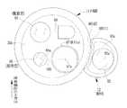
内視鏡11の先端面20aには、図3に示すように、観察窓65、照明窓66、鉗子出口67、送気・送水ノズル68などが設けられている。観察窓65には、体腔内の被観察部位の像光を取り込むための対物光学系の一部が配されている。照明窓66は、観察窓65の近くに設けられ観察範囲を照明する。照明窓66の奧には、照明光学系が内蔵されており、照明光学系は、ライトガイド60を介して光源装置13から伝送される光を体腔内の被観察部位に照射する。  As shown in FIG. 3, anobservation window 65, anillumination window 66, aforceps outlet 67, an air /water supply nozzle 68, and the like are provided on thedistal end surface 20a of theendoscope 11. In theobservation window 65, a part of an objective optical system for taking in image light of a site to be observed in the body cavity is arranged. Theillumination window 66 is provided near theobservation window 65 and illuminates the observation range. An illumination optical system is built in the ridge of theillumination window 66, and the illumination optical system irradiates the observation site in the body cavity with light transmitted from thelight source device 13 via thelight guide 60.

内視鏡11の鉗子出口67は、鉗子管路62を介して手元操作部18に設けた鉗子入口21と連通されている。送気・送水ノズル68は、手元操作部18に設けた送気・送水ボタン23を操作することによって患部に送気、送水をしたり、観察窓65に向けて洗浄水やエアーを噴射する。  Theforceps outlet 67 of theendoscope 11 is communicated with aforceps inlet 21 provided in thehand operation unit 18 via aforceps conduit 62. The air supply /water supply nozzle 68 operates the air supply /water supply button 23 provided in thehand operation unit 18 to supply or supply water to the affected area, or to inject cleaning water or air toward theobservation window 65.

観察窓65には、図4に示すように、対物光学系70の一部が配されている。照明窓66から発する照明光は、被観察部位を反射して対物光学系70に入射する。入射した被写体光は、対物光学系70を通ってプリズム71に入射してプリズム71の内部で屈曲することで撮像素子72の結像面に結像する。撮像素子72には、回路基板73が接続されており、この回路基板73には多芯ケーブル64の各信号線74が接続されている。  As shown in FIG. 4, a part of the objectiveoptical system 70 is arranged in theobservation window 65. The illumination light emitted from theillumination window 66 is reflected by the site to be observed and enters the objectiveoptical system 70. The incident subject light enters theprism 71 through the objectiveoptical system 70 and bends inside theprism 71 to form an image on the imaging surface of theimage sensor 72. Acircuit board 73 is connected to theimage sensor 72, and eachsignal line 74 of themulticore cable 64 is connected to thecircuit board 73.

内視鏡11の先端硬質部26から湾曲部27の外層は、柔軟性を有するアングルゴム75で形成されている。アングルゴム75の内側には、アングルワイヤ61の先端が係合している先端側接続リング76が設けられている。先端側接続リング76には、軟性部28に向けて、複数の節輪(図示なし)が湾曲中心となる左右及び上下のピンで交互に連結されている。各節輪の内側には、アングルワイヤ61が摺動自在に係合しており、節輪列は、上下用と左右用とのアングルワイヤ61の押し引きにより上下及び左右に湾曲する。  The outer layer from the distal endhard portion 26 to thecurved portion 27 of theendoscope 11 is formed of aflexible angle rubber 75. On the inner side of theangle rubber 75, a distal endside connection ring 76 with which the distal end of theangle wire 61 is engaged is provided. A plurality of node rings (not shown) are alternately connected to the distal endside connection ring 76 with left and right and upper and lower pins serving as the center of curvature toward theflexible portion 28. Anangle wire 61 is slidably engaged inside each node ring, and the node ring row is bent vertically and horizontally by pushing and pulling theangle wire 61 for up and down and left and right.

内視鏡11の湾曲部27の内部には、ライトガイド60が配されている。ライトガイド60は、複数の光ファイバを円形に結束させ、その周りをシリコン等の弾性を有する材料で形成した保護チューブ60aで覆った断面形状になっている。アングルゴム75の内部では、ライトガイド60の出射端77が照明レンズ78の入射面80に接するように固定されている。照明レンズ78は、入射面80とは逆側の出射面79が照明窓66となっている。この照明レンズ78が本発明の照明光学系を構成している。このライトガイド60の出射端77もアングルゴム75の内部で固定されている。  Alight guide 60 is disposed inside the bendingportion 27 of theendoscope 11. Thelight guide 60 has a cross-sectional shape in which a plurality of optical fibers are bundled in a circular shape and the periphery thereof is covered with aprotective tube 60a formed of an elastic material such as silicon. Inside theangle rubber 75, the exit end 77 of thelight guide 60 is fixed so as to contact theincident surface 80 of theillumination lens 78. Theillumination lens 78 has anexit surface 79 opposite to theentrance surface 80 serving as anillumination window 66. Thisillumination lens 78 constitutes the illumination optical system of the present invention. Theexit end 77 of thelight guide 60 is also fixed inside theangle rubber 75.

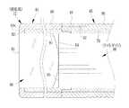
補助具12の挿入部29は、図5に示すように、内視鏡11の先端部20の輪郭の一部に沿うように円弧状に窪ませた凹部81を断面円形の一部に有する断面略三日月状となっている。断面略三日月状を構成する表皮は、内視鏡11と同じに、螺管82、ネット83、及び外層84との3層からなる可撓性管85で覆われている。螺管82は、ライトガイド86の周りに設けられており、可撓性を保ちながらライトガイド86を保護する。ネット83は、螺管82の上に被覆され外層84の樹脂を保持する。外層84は、ネット83上に樹脂を被着したものである。凹部81の外層84には、内視鏡11の磁石体30(31)に磁着する磁石体48(49)が凹部81に沿うように取り付けられている。なお、補助具12の挿入部29の輪郭形状としては、円形としてもよい。また、磁石体48,49の代わりに磁性体を用いても良い。  As shown in FIG. 5, theinsertion portion 29 of theauxiliary tool 12 has a cross section having aconcave portion 81 that is recessed in an arc shape along a part of the contour of thedistal end portion 20 of theendoscope 11. It is almost a crescent moon. Similar to theendoscope 11, the epidermis that has a substantially crescent-shaped cross section is covered with aflexible tube 85 including three layers of ascrew tube 82, a net 83, and anouter layer 84. Thescrew tube 82 is provided around thelight guide 86 and protects thelight guide 86 while maintaining flexibility. The net 83 is covered on thescrew tube 82 and holds the resin of theouter layer 84. Theouter layer 84 is formed by depositing a resin on the net 83. A magnet body 48 (49) that is magnetically attached to the magnet body 30 (31) of theendoscope 11 is attached to theouter layer 84 of therecess 81 along therecess 81. Note that the contour shape of theinsertion portion 29 of theauxiliary tool 12 may be circular. Further, instead of themagnet bodies 48 and 49, a magnetic body may be used.

補助具12のライトガイド86は、複数の光ファイバ87を円形に結束させて、その周りをシリコン等の弾性を有する材料で形成した保護チューブ88で覆った断面形状になっている。なお、保護チューブ88を除くライトガイド86の径は、内視鏡11のライトガイド60の径に対して大径になっている。  Thelight guide 86 of theauxiliary tool 12 has a cross-sectional shape in which a plurality ofoptical fibers 87 are bundled in a circular shape and the periphery thereof is covered with aprotective tube 88 formed of a material having elasticity such as silicon. Note that the diameter of thelight guide 86 excluding theprotective tube 88 is larger than the diameter of thelight guide 60 of theendoscope 11.

補助具12の先端基部44は、図6に示すように、硬質外管90で覆われている。先端基部44の内部には、レンズ保持枠91が固定され、レンズ保持枠91には照明レンズ89が保持されている。照明レンズ89は、照明光学系を構成しており、先端面44aに形成した照明窓92から出射面93が露呈している。照明レンズ89は、出射面93とは逆側の入射面94にライトガイド86の出射端95が配されている。なお、照明レンズ89としては、単レンズ以外に、複数のレンズで構成したものでもよい。補助具12に用いる照明レンズ89としては、鉗子等の影消しに加えて、内視鏡11の照明機能の光量不足を補う場合は狭い範囲、また配光角を補う場合は広い範囲になるよう入射面94の照明レンズの拡散範囲を変えてもよい。  The distalend base portion 44 of theauxiliary tool 12 is covered with a hardouter tube 90 as shown in FIG. Alens holding frame 91 is fixed inside the distalend base portion 44, and anillumination lens 89 is held on thelens holding frame 91. Theillumination lens 89 constitutes an illumination optical system, and theexit surface 93 is exposed from theillumination window 92 formed on thedistal end surface 44a. In theillumination lens 89, the exit end 95 of thelight guide 86 is disposed on theentrance surface 94 opposite to theexit surface 93. Theillumination lens 89 may be composed of a plurality of lenses in addition to a single lens. Theillumination lens 89 used for theauxiliary tool 12 has a narrow range when compensating for the insufficient light quantity of the illumination function of theendoscope 11 and a wide range when compensating for the light distribution angle, in addition to the shadowing of forceps and the like. The diffusion range of the illumination lens on theincident surface 94 may be changed.

補助具12の湾曲部45は、内視鏡11の湾曲部27に追従して湾曲するように柔軟な表皮96に覆われている。この表皮96は、可撓管部46と略同じ構成をしているが、内視鏡11の湾曲部27の湾曲に対して内側又は外側で追従して湾曲したときに、先端基部44の先端面44aが内視鏡11の先端面20aに対してずれることがないように、挿入方向に対して僅かに伸縮する。  The bendingportion 45 of theauxiliary tool 12 is covered with aflexible skin 96 so as to follow the bendingportion 27 of theendoscope 11 and bend. Theepidermis 96 has substantially the same configuration as theflexible tube portion 46, but the tip of the distalend base portion 44 is bent when following the inside or outside of the bendingportion 27 of theendoscope 11. Thesurface 44a slightly expands and contracts in the insertion direction so that it does not deviate from thedistal end surface 20a of theendoscope 11.

磁石体48(49)は、表皮96に設けた凹部97に嵌め込まれている。磁石体48(49)は、図7に示すように、先端面44aの外周のうちの一部の範囲に円弧状に取り付けられている。この一部の範囲は、内視鏡11の先端面20aに設けた鉗子出口67を挟んで照明窓66とは逆側に、補助具12の先端面44aに設けた照明窓92が配されるように補助具12の先端部50を磁着する範囲になっている。  The magnet body 48 (49) is fitted in arecess 97 provided in theskin 96. As shown in FIG. 7, the magnet body 48 (49) is attached in a circular arc shape in a part of the outer periphery of thedistal end surface 44 a. In this partial range, anillumination window 92 provided on thedistal end surface 44a of theauxiliary tool 12 is arranged on the opposite side of theillumination window 66 across theforceps outlet 67 provided on thedistal end surface 20a of theendoscope 11. In this way, thedistal end portion 50 of theauxiliary tool 12 is in a range to be magnetically attached.

磁着した時には、内視鏡11の鉗子出口67に対して照明窓66とは逆側に補助具12の照明窓92が配されるように位置決めされる。なお、内視鏡11の照明窓66の中心66aと鉗子出口67の中心67aとを結ぶ直線100上に、補助具12の照明窓92の中心92aが配されるように位置決めするのが望ましい。  When magnetized, the positioning is performed such that theillumination window 92 of theauxiliary tool 12 is disposed on the opposite side of theillumination window 66 with respect to theforceps outlet 67 of theendoscope 11. In addition, it is desirable to position so that thecenter 92a of theillumination window 92 of theauxiliary tool 12 is arranged on thestraight line 100 connecting thecenter 66a of theillumination window 66 of theendoscope 11 and thecenter 67a of theforceps outlet 67.

補助具12に設けた一対の磁石体48,49は、図8に示すように、表面に凹凸が出ないように表皮96に設けた一対の凹部97にそれぞれ嵌め込まれている。一方、内視鏡11に設けた一対の磁石体30,31も、表面に凹凸が出ないように、一段凹んだ凹部101に嵌め込まれている。内視鏡11と補助具12の湾曲部27,45の長さは同じになっており、一対の磁石体30,31と磁石体48,49を湾曲部27,45の前後の二カ所で磁着させることで、内視鏡11と補助具12との湾曲部27,45を先端面20a,44aが揃った状態で並列的に固定することができる。  As shown in FIG. 8, the pair ofmagnet bodies 48 and 49 provided in theauxiliary tool 12 are fitted in a pair ofrecesses 97 provided in theskin 96 so that the surface does not have irregularities. On the other hand, the pair ofmagnet bodies 30 and 31 provided in theendoscope 11 are also fitted into the recessedportion 101 that is recessed by one step so that the surface does not have unevenness. The lengths of the bendingportions 27 and 45 of theendoscope 11 and theauxiliary tool 12 are the same, and the pair ofmagnet bodies 30 and 31 and themagnet bodies 48 and 49 are magnetized at two places before and after the bendingportions 27 and 45. By attaching, thecurved portions 27 and 45 of theendoscope 11 and theauxiliary tool 12 can be fixed in parallel with the distal end surfaces 20a and 44a being aligned.

なお、これら磁石体30,31,48,49が本発明の固定手段を構成する。固定手段としては、磁石体同士を磁着させることに限らず、磁石体と磁着体との組でもよい。また、複数の磁石体をリング状のバンドに取り付け、そのバンドを凹部に嵌め込むようにしてもよい。  Thesemagnet bodies 30, 31, 48, and 49 constitute the fixing means of the present invention. The fixing means is not limited to magnetizing magnet bodies, but may be a set of magnet bodies and magnetized bodies. Alternatively, a plurality of magnet bodies may be attached to a ring-shaped band and the band may be fitted into the recess.

観察窓65から見ると左下に鉗子出口67が配されているので、モニタ15の画面には、図9に示すように、鉗子102が左斜め下から突出するのが視認され、また観察窓65から見ると鉗子出口67の右側に照明窓66が配されているので、鉗子102及び鉗子片103の左側が影となって表れる。補助具12を併用すると、観察窓65から見て左方に補助具12の照明窓92が配されるので、補助具12の照明が鉗子102及び鉗子片103の左側を照明することになり、よって、鉗子102及び鉗子片103の影104をなくすことができる。  Since theforceps outlet 67 is arranged at the lower left when viewed from theobservation window 65, it is visually recognized on the screen of themonitor 15 that theforceps 102 protrude from the diagonally lower left as shown in FIG. Since theillumination window 66 is arranged on the right side of theforceps outlet 67, the left side of theforceps 102 and theforceps piece 103 appears as a shadow. When theauxiliary tool 12 is used in combination, theillumination window 92 of theauxiliary tool 12 is arranged on the left side when viewed from theobservation window 65, so that the illumination of theauxiliary tool 12 illuminates the left side of theforceps 102 and theforceps piece 103. Therefore, theshadow 104 of theforceps 102 and theforceps piece 103 can be eliminated.

また、補助具12の照明が広い範囲に配光すると、鉗子出口67に対して補助具12とは逆側に鉗子や鉗子片の影ができなる不都合が生じるおそれがある。そこで、図10に示すように、内視鏡11と補助具12の挿入部16,29の先端面20a,44aから観察方向に向けた任意の撮像距離において、補助具12の照明レンズ89から出射する光束98が、内視鏡11の鉗子出口67から鉗子を導き出す軸(鉗子導出軸)69にかからない配光特性をもつ照明レンズ89を用いるのが好適である。なお、符号59は、鉗子が出入りする軌跡の範囲を示している。また、軸69と照明レンズ89の光軸89aとは略平行になっている。  In addition, when the illumination of theauxiliary tool 12 is distributed over a wide range, there is a possibility that the forceps and the forceps pieces may be shadowed on the opposite side of theauxiliary tool 12 with respect to theforceps outlet 67. Accordingly, as shown in FIG. 10, the light is emitted from theillumination lens 89 of theauxiliary tool 12 at an arbitrary imaging distance from the distal end surfaces 20a and 44a of theinsertion portions 16 and 29 of theendoscope 11 and theauxiliary tool 12 in the observation direction. It is preferable to use anillumination lens 89 having a light distribution characteristic in which theluminous flux 98 is not applied to the axis (forceps lead-out axis) 69 for guiding the forceps from theforceps outlet 67 of theendoscope 11.Reference numeral 59 indicates the range of the trajectory where the forceps enter and exit. Theaxis 69 and theoptical axis 89a of theillumination lens 89 are substantially parallel.

内視鏡11は、図11に示す撮像素子72を先端硬質部26に備え、また、CPU105、基準クロック発振器106、タイミングジェネレータ(TG)107、及びアナログ信号処理回路(AFE:Analog Front End processor)108等をユニバーサルコネクタ19の内部に備えている。  Theendoscope 11 includes theimage sensor 72 shown in FIG. 11 at the distal endhard portion 26, and further includes aCPU 105, a reference clock oscillator 106, a timing generator (TG) 107, and an analog signal processing circuit (AFE: Analog Front End processor). 108 etc. are provided inside theuniversal connector 19.

撮像素子72は、CCDやCMOS等であり、対物光学系70により結像する被写体像を撮像する。この受光面には、複数の色セグメントからなるカラーフィルタ(例えば、ベイヤー配列の原色カラーフィルタ)が配置されている。Theimage sensor 72 is a CCD, a CMOS, or the like, and captures a subject image formed by the objectiveoptical system 70. On this light receiving surface, a color filter composed of a plurality of color segments (for example, a primary color filter with a Bayer array) is arranged.

CPU105は、内視鏡11の各部の動作制御を行う。TG107は、基準クロック発振器106により生成される基準クロック信号に基づき、撮像素子72の駆動パルス(垂直/水平駆動パルス)を生成するとともに、AFE108用の同期パルスを生成し、前記駆動パルス及び同期パルスをそれぞれ撮像素子72、及びAFE108に入力する。撮像素子72は、TG107から入力された駆動パルスに応じて撮像動作を行い、撮像信号をAFE108に出力する。  TheCPU 105 controls the operation of each part of theendoscope 11. TheTG 107 generates a drive pulse (vertical / horizontal drive pulse) for theimage sensor 72 based on the reference clock signal generated by the reference clock oscillator 106, and generates a synchronization pulse for theAFE 108, and the drive pulse and the synchronization pulse. Are input to theimage sensor 72 and theAFE 108, respectively. Theimaging element 72 performs an imaging operation according to the drive pulse input from theTG 107 and outputs an imaging signal to theAFE 108.

AFE108は、相関二重サンプリング回路(CDS)110、自動ゲイン制御回路(AGC)111、及びアナログ/デジタル変換器(A/D)112により構成されている。CDS110は、撮像素子72から出力される撮像信号に対して相関二重サンプリング処理を施し、撮像素子72で生じるリセット雑音及びアンプ雑音の除去を行う。AGC111は、CDS110によりノイズ除去が行われた撮像信号をゲイン調整する。A/D112は、AGC111により増幅された撮像信号を、所定のビット数のデジタル信号に変換し、ユニバーサルコネクタ19を介してプロセッサ装置14に送る。  TheAFE 108 includes a correlated double sampling circuit (CDS) 110, an automatic gain control circuit (AGC) 111, and an analog / digital converter (A / D) 112. TheCDS 110 performs correlated double sampling processing on the image signal output from theimage sensor 72, and removes reset noise and amplifier noise generated in theimage sensor 72. TheAGC 111 adjusts the gain of the image signal from which noise has been removed by theCDS 110. The A /D 112 converts the imaging signal amplified by theAGC 111 into a digital signal having a predetermined number of bits, and sends the digital signal to theprocessor device 14 via theuniversal connector 19.

また、TG107は、AFE108から出力される撮像信号に対応した、水平同期信号、垂直同期信号、及びクロック信号を、それぞれユニバーサルコネクタ19を介してプロセッサ装置14に送る。  Further, theTG 107 sends a horizontal synchronization signal, a vertical synchronization signal, and a clock signal corresponding to the imaging signal output from theAFE 108 to theprocessor device 14 via theuniversal connector 19.

プロセッサ装置14は、CPU113、アイソレーション回路(絶縁回路)114、デジタル信号処理回路(DSP)115、同期信号発生回路(SSG)116、及びデジタル/アナログ変換器(D/A)117等を備えている。  Theprocessor device 14 includes aCPU 113, an isolation circuit (insulation circuit) 114, a digital signal processing circuit (DSP) 115, a synchronization signal generation circuit (SSG) 116, a digital / analog converter (D / A) 117, and the like. Yes.

CPU113は、プロセッサ装置14、及び光源装置13の動作制御を行う。アイソレーション回路114は、内視鏡11をプロセッサ装置14から絶縁分離するためのものである。デジタル信号処理回路(DSP)115は、撮像信号に信号処理を施して映像信号(ビデオ信号)を生成する。  TheCPU 113 controls the operation of theprocessor device 14 and thelight source device 13. Theisolation circuit 114 is for isolating theendoscope 11 from theprocessor device 14. A digital signal processing circuit (DSP) 115 performs signal processing on the imaging signal to generate a video signal (video signal).

同期信号発生回路(SSG)116は、補正された水平同期信号、垂直同期信号、及びクロック信号を発生する。デジタル/アナログ変換器(D/A)117は、DSP115から出力された映像信号をNTSC方式等のアナログ映像信号に変換する。  A synchronization signal generation circuit (SSG) 116 generates a corrected horizontal synchronization signal, vertical synchronization signal, and clock signal. A digital / analog converter (D / A) 117 converts the video signal output from theDSP 115 into an analog video signal of the NTSC system or the like.

SSG116には、内視鏡11のTG107から出力された水平駆動パルス、垂直駆動パルス、及びクロックパルスがアイソレーション回路114を介して入力される。SSG116は、入力された水平駆動パルス、垂直駆動パルス、及びクロックパルスの間の位相ずれを補正して、位相ずれが補正された水平駆動パルス、垂直駆動パルス、及びクロックパルスを発生し、これらの信号をDSP115に入力する。  A horizontal drive pulse, a vertical drive pulse, and a clock pulse output from theTG 107 of theendoscope 11 are input to theSSG 116 via theisolation circuit 114. TheSSG 116 corrects a phase shift between the input horizontal drive pulse, vertical drive pulse, and clock pulse, and generates a horizontal drive pulse, a vertical drive pulse, and a clock pulse with corrected phase shift. A signal is input to theDSP 115.

DSP115には、内視鏡11のAFE108から出力された撮像信号がアイソレーション回路114を介して入力される。DSP115は、入力された撮像信号に対し、色分離、色補間、ゲイン補正、ホワイトバランス調整、ガンマ補正、画像強調処理等を行い、輝度(Y)信号と色差(C)信号とからなるY/C形式の映像信号を生成し、生成した映像信号をD/A117に入力する。D/A117は、入力された映像信号をNTSC方式のアナログ映像信号に変換し、コネクタ118に外部接続されたモニタ15に出力する。  An imaging signal output from theAFE 108 of theendoscope 11 is input to theDSP 115 via theisolation circuit 114. TheDSP 115 performs color separation, color interpolation, gain correction, white balance adjustment, gamma correction, image enhancement processing, and the like on the input imaging signal, and generates a Y / Y consisting of a luminance (Y) signal and a color difference (C) signal. A C format video signal is generated, and the generated video signal is input to the D /A 117. The D /A 117 converts the input video signal into an NTSC analog video signal and outputs the analog video signal to themonitor 15 externally connected to theconnector 118.

光源装置13は、光源ランプ120、光源ドライバ121、絞り機構122、光量制限機構123、集光レンズ124、及びCPU125を備えている。光源ランプ120は、キセノンランプやハロゲンランプ等から放たれる白色の光源である。光源ドライバ121は、光源ランプ120を駆動する。絞り機構122は、光源ランプ120とライトガイド60,86の入射端126,127との間に配され、ライトガイド60,86への入射光量を増減させる。光量制限機構123は、照明光の光路上に光量制限フィルタを挿脱する機構であり、そのフィルタを挿入すると白色光の所定波長域の光量を制限する。集光レンズ124は、絞り機構122を通過した光を集光してライトガイド60,86の入射端126,127に導く。CPU125は、プロセッサ装置14のCPU113と通信し、ビデオ信号を生成するときに得られる明るさ情報を取得し、その明るさ情報に基づいて光源ドライバ121での光源ランプ120の光量、及び絞り機構122での絞りの開閉動作の制御を行って照明光を調光する。  Thelight source device 13 includes alight source lamp 120, alight source driver 121, adiaphragm mechanism 122, a lightamount limiting mechanism 123, acondenser lens 124, and aCPU 125. Thelight source lamp 120 is a white light source emitted from a xenon lamp, a halogen lamp, or the like. Thelight source driver 121 drives thelight source lamp 120. Theaperture mechanism 122 is disposed between thelight source lamp 120 and the incident ends 126 and 127 of the light guides 60 and 86, and increases or decreases the amount of light incident on the light guides 60 and 86. The lightamount limiting mechanism 123 is a mechanism that inserts and removes a light amount limiting filter on the optical path of the illumination light. When the filter is inserted, the lightamount limiting mechanism 123 limits the amount of white light in a predetermined wavelength range. The condensinglens 124 condenses the light that has passed through theaperture mechanism 122 and guides it to the incident ends 126 and 127 of the light guides 60 and 86. TheCPU 125 communicates with theCPU 113 of theprocessor device 14 to acquire brightness information obtained when generating a video signal, and based on the brightness information, the light amount of thelight source lamp 120 in thelight source driver 121 and theaperture mechanism 122. The illumination light is dimmed by controlling the opening / closing operation of the diaphragm at.

光源ランプ120から発せられた光は、絞り機構122、及び集光レンズ124を介して調光されて照明光として、内視鏡11のライトガイド60と補助具12のライトガイド86との入射端126,127にそれぞれ入射する。内視鏡11のライトガイド60の出射端77から出射される光は、照明レンズ78を介して照明窓66から体腔内へ照射され、また、補助具12のライトガイド86の出射端95から出射される光は、照明レンズ89を介して照明窓92から体内に照射される。  The light emitted from thelight source lamp 120 is dimmed through thediaphragm mechanism 122 and thecondenser lens 124 and is used as illumination light as incident light between thelight guide 60 of theendoscope 11 and thelight guide 86 of theauxiliary tool 12. 126 and 127, respectively. Light emitted from theemission end 77 of thelight guide 60 of theendoscope 11 is irradiated into the body cavity from theillumination window 66 via theillumination lens 78, and is emitted from theemission end 95 of thelight guide 86 of theauxiliary tool 12. The emitted light is irradiated into the body from theillumination window 92 via theillumination lens 89.

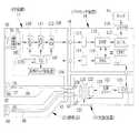
内視鏡11の先端面20aに設けた送気・送水ノズル68には、図12に示すように、送気・送水管路63が接続されている。送気・送水管路63の後端は、送気用管路130と送水用管路131との二股に分かれている。送気用管路130と送水用管路131は、送気・送水ボタン23に各々接続されている。送気・送水ボタン23は、周知のように、管路切換機能を有し、送気用ポート、送水用ポート、給水用ポート、及び、給気用ポートを有している。送水用ポートには送水用管路131が、送気用ポートには送気用管路130が接続されている。また、給水用ポートには、ユニバーサルコネクタ19に設けた送水コネクタ132を介して送水タンク133が接続される。給気用ポートには、ユニバーサルコネクタ19を介して光源装置13に内蔵したバルブ134、及び送気ポンプ135が接続される。  As shown in FIG. 12, an air /water supply conduit 63 is connected to the air /water supply nozzle 68 provided on thedistal end surface 20a of theendoscope 11. The rear end of the air /water supply pipe 63 is divided into a bifurcated section of anair supply pipe 130 and awater supply pipe 131. Theair supply conduit 130 and thewater supply conduit 131 are connected to the air /water supply button 23, respectively. As is well known, the air /water supply button 23 has a pipeline switching function, and has an air supply port, a water supply port, a water supply port, and an air supply port. Awater supply conduit 131 is connected to the water supply port, and anair supply conduit 130 is connected to the air supply port. In addition, awater supply tank 133 is connected to the water supply port via awater supply connector 132 provided in theuniversal connector 19. Avalve 134 built in thelight source device 13 and anair supply pump 135 are connected to the air supply port via theuniversal connector 19.

光源装置13には、送気圧を選択する送気ボタン136が外部に設けられている。送気ボタン136で選択した送気圧の情報はCPU125に送られ、CPU125は送気圧の情報に基づいてバルブ134の弁を調節する。送気・送水ボタン23には、ボタンの一部に孔が空いており、送気ポンプ135は、常に駆動して前記孔から空気を吐出している。送気・送水ボタン23の孔を塞ぐ操作を行うことで、送気・送水ノズル68までの管路が繋がり、送気・送水ノズル68より空気が吹き出す。さらに、送気・送水ボタン23を押し込む操作を行うと、給気用ポートが塞がれ、空気は送水タンク133に流れ込む。空気は、送水タンク133内の水を押し出し、水は給水用ポートを介して送水用ポートから送気・送水管路63を経て送気・送水ノズル68から吹き出す。  Thelight source device 13 is provided with anair supply button 136 for selecting an air pressure. The air pressure information selected by theair feed button 136 is sent to theCPU 125, and theCPU 125 adjusts thevalve 134 based on the air pressure information. The air /water supply button 23 has a hole in a part of the button, and theair supply pump 135 is always driven to discharge air from the hole. By performing an operation of closing the hole of the air /water supply button 23, the pipeline to the air /water supply nozzle 68 is connected, and air blows out from the air /water supply nozzle 68. Further, when an operation of pushing the air /water supply button 23 is performed, the air supply port is blocked and the air flows into thewater supply tank 133. The air pushes out the water in thewater supply tank 133, and the water blows out from the air supply /water supply nozzle 68 through the water supply port through the air supply /water supply conduit 63 through the water supply port.

内視鏡11の鉗子管路62の後端は、鉗子入口21と手元操作部18に設けた吸引ボタン24とに分岐して接続されている。吸引ボタン24には、鉗子管路62に繋がるポート137と、ユニバーサルコネクタ19に設けた吸引コネクタ138に繋がるポート139とを有する。吸引コネクタ138には、吸引装置140に繋がるチューブ141が接続される。吸引ボタン24の押下操作によりポート137,139が繋がり、吸引装置140は、内視鏡11の鉗子管路62を介して鉗子出口67から体腔内の汚物や血液その他の体液を吸引し、吸引タンク149に貯留する。  The rear end of theforceps conduit 62 of theendoscope 11 is branched and connected to theforceps inlet 21 and thesuction button 24 provided in thehand operation unit 18. Thesuction button 24 has aport 137 connected to theforceps conduit 62 and aport 139 connected to thesuction connector 138 provided in theuniversal connector 19. Atube 141 connected to thesuction device 140 is connected to thesuction connector 138. When thesuction button 24 is pressed, theports 137 and 139 are connected, and thesuction device 140 sucks filth and blood and other body fluids in the body cavity from theforceps outlet 67 via theforceps conduit 62 of theendoscope 11 and sucks the suction tank. Store in 149.

光源装置13の前面には、図13に示すように、右寄りに電源ボタン145が設けられている。電源ボタン145のオン/オフ操作をすることにより商用電源から光源装置13への電力の供給及び停止が行われる。電源ボタン145の左横には、ランプ点灯ボタン146、明るさ調整ボタン147、及び光量制限ボタン148等が順に並んで設けられている。光源装置13の前面左側には、内視鏡のLG用コネクタ32を接続するLG用ソケット36が、また、補助具12の補助LG用コネクタ41を接続する補助LG用ソケット43がそれぞれ設けられている。  As shown in FIG. 13, apower button 145 is provided on the front side of thelight source device 13 on the right side. By turning on / off thepower button 145, power supply from the commercial power supply to thelight source device 13 is stopped. On the left side of thepower button 145, alamp lighting button 146, abrightness adjustment button 147, a lightamount restriction button 148, and the like are provided in order. AnLG socket 36 for connecting theLG connector 32 of the endoscope and anauxiliary LG socket 43 for connecting theauxiliary LG connector 41 of theauxiliary tool 12 are respectively provided on the left side of the front surface of thelight source device 13. Yes.

ランプ点灯ボタン146は、プッシュ式の押しボタンスイッチとなっており、オン/オフ操作をすることにより、前記光源の点灯、及び消灯を行う。明るさ調整ボタン147は、アップボタン147a、及びダウンボタン147bとで構成されており、絞りの開口口径を制御して照明光の明るさを、例えば10段階で調整する。なお、絞りの代わりに、減衰フィルタの挿入、あるいは光源ランプの点灯電流の調節等によって明るさ調整をすることもできる。光量制限ボタン148は、プッシュ式の押しボタンであり、オン/オフ操作をすることで、照明光の光路上に光量制限フィルタを挿脱して白色光の所定波長域の光量を制限するか否かを選択する。  Thelamp lighting button 146 is a push-type push button switch, and turns on and off the light source by performing an on / off operation. Thebrightness adjustment button 147 includes an upbutton 147a and adown button 147b, and adjusts the brightness of the illumination light by, for example, 10 steps by controlling the aperture diameter of the diaphragm. The brightness can be adjusted by inserting an attenuation filter or adjusting the lighting current of the light source lamp instead of the diaphragm. The lightamount limiting button 148 is a push-type push button, and whether or not to limit the light amount of the white light in a predetermined wavelength range by inserting / removing the light amount limiting filter on the optical path of the illumination light by performing an on / off operation. Select.

内視鏡11を用いて検診あるいは観察する前には、被検者のデータや、診断や観察部位に応じて、ランプの明るさや照明光の波長の指定を行う。例えば、光源装置13では、電源ボタン145をオンし、その後ランプ点灯ボタン146をオンし、被写体の明るさが適切になるように明るさ調整ボタン147で調整し、光量制限ボタン148のオン/オフを決定する。  Before examination or observation using theendoscope 11, the brightness of the lamp and the wavelength of the illumination light are designated according to the data of the subject, the diagnosis, and the observation site. For example, in thelight source device 13, thepower button 145 is turned on, and then thelamp lighting button 146 is turned on, thebrightness adjustment button 147 is adjusted so that the brightness of the subject is appropriate, and the lightquantity restriction button 148 is turned on / off. To decide.

次に上記構成の作用を、図14を参照しながら説明する。経鼻内視鏡検査では、まず前処置として、内視鏡11の挿入部16を挿入するために外鼻孔の奧の鼻腔から中(下)鼻道に麻酔を行うとともに挿通テストを行い、挿入部16が挿通可能な挿入経路のある鼻腔を決定する。前処置は座位又は仰臥位で行い、その後に、仰臥位又は左側臥位で挿入部16を一方の外鼻孔に挿入していく。挿入経路は、図15に示すように、一方の外鼻孔150から中鼻道151又は下鼻道152を通して後鼻孔(内鼻孔)153、食道154、そして胃へと到達させる経路である。  Next, the operation of the above configuration will be described with reference to FIG. In the transnasal endoscopy, as a pretreatment, in order to insert theinsertion part 16 of theendoscope 11, an anesthesia is performed from the nasal cavity of the nostril to the middle (lower) nasal passage and an insertion test is performed. The nasal cavity having an insertion path through which theunit 16 can be inserted is determined. The pretreatment is performed in the sitting position or the supine position, and thereafter, theinsertion portion 16 is inserted into one outer nostril in the supine position or the left-side supine position. As shown in FIG. 15, the insertion path is a path that reaches from one outer nostril 150 through the middlenasal passage 151 or the lower nasal passage 152 to the posterior nostril (inner nostril) 153, theesophagus 154, and the stomach.

十二指腸や胃等を観察し、患部を見つけたときには、内視鏡11で処理可能か否かを判断する。処置可能の場合には、鉗子等の処置具を用いて処理又は治療を行う。処置具は、内視鏡11の鉗子入口21に挿入し、鉗子片を鉗子出口67から突出する。鉗子には、基端にハンドルが設けられており、鉗子入口21の外でハンドルをスライド操作することで、鉗子片が可動する。このとき、図9で説明したように、モニタ15の画面上では、鉗子及び鉗子片の左側が影となって表れる。この影により患部を鮮明に視認することができないおそれがある。この場合に補助具12を併用する。  When the duodenum, stomach, etc. are observed and an affected part is found, it is determined whether or not processing is possible with theendoscope 11. When treatment is possible, treatment or treatment is performed using a treatment tool such as forceps. The treatment instrument is inserted into theforceps inlet 21 of theendoscope 11 and the forceps piece protrudes from theforceps outlet 67. The forceps is provided with a handle at the base end, and the forceps piece is moved by sliding the handle outside theforceps inlet 21. At this time, as described in FIG. 9, the left side of the forceps and the forceps piece appears as a shadow on the screen of themonitor 15. There is a possibility that the affected part cannot be clearly seen by this shadow. In this case, theauxiliary tool 12 is used together.

補助具12を内視鏡11と併用する場合、まず補助具12の挿入部29を他方の外鼻孔に挿入するため、他方の外鼻孔の奧の鼻腔に麻酔を行う。次に、内視鏡11と補助具12との挿入部16,29の先端部20,50を固定して一緒に挿入する必要があるため、内視鏡11の挿入部16をいったん後鼻孔153から食道154までの範囲に先端部20が位置するように引き戻す。その後に、補助具12の挿入部29を他方の外鼻孔から挿入し、中鼻道151又は下鼻道152を通して、後鼻孔153から食道154までの範囲に挿入する。これにより、両方の挿入部16,29の先端面20a、44aが略同じ位置となるように互いの挿入部16,29を相対的にずらして、内視鏡11の磁石体30と補助具12の磁石体48とを、また、内視鏡11の磁石体31と補助具12の磁石体49とを磁着させる。これにより、双方の湾曲部27,45が並列して密着し、双方の先端面20a,44aが同じ向きとなる。  When theauxiliary tool 12 is used in combination with theendoscope 11, first, theinsertion part 29 of theauxiliary tool 12 is inserted into the other nostril, so that the nasal cavity of the other nostril is anesthetized. Next, since it is necessary to fix and insert thedistal end portions 20 and 50 of theinsertion portions 16 and 29 of theendoscope 11 and theauxiliary tool 12 together, theinsertion portion 16 of theendoscope 11 is once inserted into the rear nostril 153. To theesophagus 154, thetip 20 is pulled back. Thereafter, theinsertion portion 29 of theauxiliary tool 12 is inserted from the other nostril, and is inserted into the range from the rear nostril 153 to theesophagus 154 through the middlenasal passage 151 or the lower nasal passage 152. As a result, theinsertion parts 16 and 29 are relatively displaced so that the distal end surfaces 20a and 44a of both theinsertion parts 16 and 29 are substantially at the same position, and themagnet body 30 and theauxiliary tool 12 of theendoscope 11 are thereby displaced. Themagnet body 48 and themagnet body 31 of theendoscope 11 and themagnet body 49 of theauxiliary tool 12 are magnetized. Thereby, both thecurved parts 27 and 45 are closely adhered in parallel, and both the front end surfaces 20a and 44a are in the same direction.

次に、補助具12の把持部40を内視鏡11の把持部17に取り付ける。この作業は、被係合部51,52を係合部53,54に係合させることで行える。これにより、補助具12の把持部40と内視鏡11の把持部17とを一体的に取り扱うことができるので、その後の作業が簡便に行える。  Next, thegrip part 40 of theauxiliary tool 12 is attached to thegrip part 17 of theendoscope 11. This operation can be performed by engaging the engagedportions 51 and 52 with the engagingportions 53 and 54. Thereby, since the holdingpart 40 of theauxiliary tool 12 and the holdingpart 17 of theendoscope 11 can be handled integrally, the subsequent work can be easily performed.

その後、補助具12の補助LG用コネクタ41を光源装置13の補助LG用ソケット43に接続する。ランプ点灯ボタン146はオンしたままになっている。このため、補助LG用ソケット43には、光漏れを防止するキャップが装着されている。このキャップ外して接続する。接続完了後、双方の挿入部16,29を徐々に挿入していく。このとき、モニタ15の画面を見ながら湾曲操作ノブ22を操作して内視鏡11の湾曲部27を湾曲させながら挿入を行っていく。補助具12の湾曲部45は、磁石体30,31と磁石体48,49との磁着により内視鏡11の湾曲部27に密着しているため、内視鏡11の湾曲部27と一緒に湾曲し、また、内視鏡11の挿入部16の挿入に追従して挿入される。このため、内視鏡11の挿入部16のみをもって挿入していくだけで補助具12の挿入部29も一緒に挿入される。Thereafter, theauxiliary LG connector 41 of theauxiliary tool 12 is connected to theauxiliary LG socket 43 of thelight source device 13. Thelamp lighting button 146 remains on. For this reason, theauxiliary LG socket 43 is provided with a cap for preventing light leakage. Remove this cap and connect. After the connection is completed, bothinsertion portions 16 and 29 are gradually inserted. At this time, the bendingoperation knob 22 is operated while viewing the screen of themonitor 15 to insert the bendingportion 27 of theendoscope 11 while bending it. Since the bendingportion 45 of theauxiliary tool 12 is in close contact with the bendingportion 27 of theendoscope 11 by the magnetic attachment of themagnet bodies 30 and 31 and themagnet bodies 48 and 49, the bendingportion 45 of theauxiliary tool 12 is combined with the bendingportion 27 of theendoscope 11. And is inserted following the insertion of theinsertion portion 16 of theendoscope 11. For this reason, theinsertion part 29 of theauxiliary tool 12 is also inserted together by only inserting with theinsertion part 16 of theendoscope 11.

その後は、モニタ15の画面で観察し、処置又は治療を施す必要のある場合には、内視鏡11の鉗子管路62を使って、スネアや生検鉗子等の処置具で処置又は治療を行う。  After that, when it is necessary to observe on the screen of themonitor 15 and perform treatment or treatment, the treatment or treatment is performed with a treatment tool such as a snare or a biopsy forceps using theforceps conduit 62 of theendoscope 11. Do.

補助具12を併用すると、図7で説明したように、観察窓65から見て左方に補助具12の先端面44aが配されるので、鉗子及び鉗子片の左側を照明することになり、よって、鉗子及び鉗子片の影をなくすことができる。また、鉗子片が開いた状態であっても、その前方にある患部を明るく照明して、良好な内視鏡観察下に鉗子処置を行うことができる。  When theauxiliary tool 12 is used in combination, thedistal end surface 44a of theauxiliary tool 12 is disposed on the left side when viewed from theobservation window 65 as shown in FIG. 7, so that the left side of the forceps and the forceps piece is illuminated. Therefore, the shadow of the forceps and the forceps piece can be eliminated. Even when the forceps piece is open, the affected part in front of the forceps can be brightly illuminated, and the forceps treatment can be performed under good endoscopic observation.

治療又は処置を終了した後には、生検鉗子又はスネア等の処置具を、内視鏡11の鉗子入口21から引き抜く。しかる後に、双方の挿入部16,29を鼻孔からゆっくりと引き抜いていく。この途中、例えば後鼻孔から食道までの範囲を通過するまでに、双方の挿入部16,29の先端部20,50の固定を解除する。この操作は、内視鏡11の挿入部16と補助具12の挿入部29とのいずれか一方を他方に対して挿入方向に相対的にずらすことで磁石体30,31と磁石体48,49との磁着を解除することができる。双方の先端部20,50の固定を解除した後には、補助具12、内視鏡11の順に挿入部29,16を個別に引き抜く。最後に、ランプ点灯ボタン146をオフしてから、補助具12の補助LG用コネクタ41を光源装置13の補助LG用ソケット43から取り外す。なお、最初から補助具12を併用してもよい。  After the treatment or treatment is completed, a treatment tool such as a biopsy forceps or a snare is pulled out from theforceps inlet 21 of theendoscope 11. Thereafter, bothinsertion portions 16, 29 are slowly pulled out from the nostril. In the middle of this, for example, before passing through the range from the posterior nostril to the esophagus, thedistal end portions 20 and 50 of bothinsertion portions 16 and 29 are released from being fixed. This operation is performed by shifting one of theinsertion portion 16 of theendoscope 11 and theinsertion portion 29 of theauxiliary tool 12 relative to the other in the insertion direction, and themagnet bodies 30 and 31 and themagnet bodies 48 and 49. Can be released. After releasing the fixing of thedistal end portions 20 and 50, theinsertion portions 29 and 16 are pulled out individually in the order of theauxiliary tool 12 and theendoscope 11. Finally, after thelamp lighting button 146 is turned off, theauxiliary LG connector 41 of theauxiliary tool 12 is removed from theauxiliary LG socket 43 of thelight source device 13. In addition, you may use theauxiliary tool 12 together from the beginning.

上記実施形態の内視鏡11は、先端面20aに照明窓66が一つのみ設けられているが、図16に示すように、観察窓65を挟んだ両側に照明窓161,162が一対設けられている内視鏡160を用いても良い。この場合には、内視鏡160の鉗子出口67に対して照明窓161とは逆側に補助具12の照明窓92を配してもよいし、内視鏡160の鉗子出口67に対して照明窓162とは逆側に補助具12’の照明窓92’を配してもよい。よって、この場合は、内視鏡11の磁石体163、164を、補助具12の先端部50がその二位置に位置決めされる範囲に設けられている。なお、内視鏡160の照明窓161の中心161aと鉗子出口67の中心67aとを結ぶ直線165上に、補助具12の照明窓92の中心92aが配されるように、内視鏡160の磁石体163,164を設けるのが望ましい。また、内視鏡160の照明窓162の中心162aと鉗子出口67の中心67aとを結ぶ直線166上に、補助具12の照明窓92’の中心92a’が配されるように、内視鏡160の磁石体163,164を設けてもよい。  In theendoscope 11 of the above embodiment, only oneillumination window 66 is provided on thedistal end surface 20a, but as shown in FIG. 16, a pair ofillumination windows 161 and 162 are provided on both sides of theobservation window 65. Anendoscope 160 may be used. In this case, theillumination window 92 of theauxiliary tool 12 may be arranged on the opposite side of theillumination window 161 with respect to theforceps outlet 67 of theendoscope 160, or theforceps outlet 67 of theendoscope 160. Anillumination window 92 ′ of theauxiliary tool 12 ′ may be arranged on the side opposite to theillumination window 162. Therefore, in this case, themagnet bodies 163 and 164 of theendoscope 11 are provided in a range where thedistal end portion 50 of theauxiliary tool 12 is positioned at the two positions. Theendoscope 160 is arranged such that thecenter 92a of theillumination window 92 of theauxiliary tool 12 is arranged on astraight line 165 connecting thecenter 161a of theillumination window 161 of theendoscope 160 and thecenter 67a of theforceps outlet 67. It is desirable to provide themagnet bodies 163 and 164. In addition, theendoscope 92 is arranged such that thecenter 92a ′ of theillumination window 92 ′ of theauxiliary tool 12 is arranged on astraight line 166 connecting thecenter 162a of theillumination window 162 of theendoscope 160 and thecenter 67a of theforceps outlet 67. 160magnet bodies 163 and 164 may be provided.

また、上記各実施形態では、補助具12に一つの照明窓を設けているが、図17に示すように、2つの照明窓171,172を設けた補助具170を用いても良い。この内視鏡160は、周面の二箇所の位置に磁石体173が設けられている。補助具170には、周面の一部に磁石体175が設けられており、鉗子出口67に対して照明窓161とは逆側で、かつ照明窓161の中心161-aと鉗子出口67の中心67aとを結ぶ直線176上に、補助具170の照明窓172の中心172aが配されるように、磁石体175が磁石体173に磁着される。  Moreover, in each said embodiment, although the one illumination window was provided in theauxiliary tool 12, as shown in FIG. 17, you may use theauxiliary tool 170 which provided the two illumination windows 171,172. Theendoscope 160 is provided withmagnet bodies 173 at two positions on the peripheral surface. Theauxiliary tool 170 is provided with amagnet body 175 on a part of the peripheral surface thereof, on the opposite side of theforceps outlet 67 from theillumination window 161 and between the center 161-a of theillumination window 161 and theforceps outlet 67. Themagnet body 175 is magnetically attached to themagnet body 173 so that thecenter 172a of theillumination window 172 of theauxiliary tool 170 is arranged on astraight line 176 connecting thecenter 67a.

補助具170の一方の照明窓171は、図18に示すように、内蔵する照明レンズ178により、光が拡散するのを抑えて狭い範囲180に配光するスポット照明(ハイビーム照明)となっており、中心172aが直線176上に位置する他方の照明窓172は、内蔵する照明レンズ179によって広い範囲181に配光する拡散照明(ロービーム照明)となっている。なお、照明レンズ178,183の光軸178a,179aは平行になっている。  As shown in FIG. 18, oneillumination window 171 of theauxiliary tool 170 is a spot illumination (high beam illumination) that suppresses light diffusion and distributes light in anarrow range 180 by a built-inillumination lens 178. Theother illumination window 172 whosecenter 172a is located on thestraight line 176 is diffuse illumination (low beam illumination) that distributes light over awide range 181 by the built-inillumination lens 179. Theoptical axes 178a and 179a of theillumination lenses 178 and 183 are parallel.

また、図18で説明した実施形態では、補助具170の先端面44aから観察方向に向けた任意の撮像距離において、照明レンズ179によって照射される所定の照度を有する第1の照射範囲Bが、照明レンズ178により照射される前記所定の照度を有する第2の照射範囲Aよりも広なる。このように、ロービーム照明により鉗子の影消しが行え、ハイビーム照明では、内視鏡11の照明窓161が1つであるための照明光量を増やすことができる。なお、図18に示す符号182,183は、ライトガイドである。  In the embodiment described with reference to FIG. 18, the first irradiation range B having a predetermined illuminance irradiated by theillumination lens 179 at an arbitrary imaging distance from thedistal end surface 44a of theauxiliary tool 170 in the observation direction is It becomes wider than the second irradiation range A having the predetermined illuminance irradiated by theillumination lens 178. In this way, the forceps can be shaded by the low beam illumination, and the amount of illumination light for thesingle illumination window 161 of theendoscope 11 can be increased in the high beam illumination.Reference numerals 182 and 183 shown in FIG. 18 are light guides.

また、図19に示すように、4つの照明窓186〜189を設けた補助具185を用いても良い。この場合には、内視鏡160の外周に設けた磁石体184と、補助具185に外周に設けた187との一箇所での磁着により、補助具185の照明窓186,187が内視鏡160の鉗子出口67を挟んで内視鏡160の照明窓162とは逆側に配され、また、補助具185の照明窓188,189が内視鏡160の鉗子出口67を挟んで内視鏡160の照明窓161とは逆側に配される。  Moreover, as shown in FIG. 19, you may use theauxiliary tool 185 which provided the four illumination windows 186-189. In this case, theillumination windows 186 and 187 of theauxiliary tool 185 are internally viewed by magnetizing at one location of themagnet body 184 provided on the outer periphery of theendoscope 160 and the 187 provided on the outer periphery of theauxiliary tool 185. Theforceps outlet 67 of themirror 160 is disposed on the opposite side of theillumination window 162 of theendoscope 160, and theillumination windows 188 and 189 of theauxiliary tool 185 are endoscopically sandwiched with theforceps outlet 67 of theendoscope 160. Themirror 160 is disposed on the opposite side of theillumination window 161.

特に、補助具185の照明窓186,187は、中心186a,187aが内視鏡160の照明窓162の中心162aと鉗子出口67の中心67aを通る直線176上に配され、また、補助具185の照明窓188,189は、中心188a,189aが内視鏡160の照明窓161の中心161aと鉗子出口67の中心67aを通る直線177上に配される。そして、内視鏡11に接近した位置に配される照明窓186,188がハイビーム照明となっており、遠ざかる位置に配される照明窓188,189がロービーム照明になっている。  In particular, theillumination windows 186 and 187 of theauxiliary tool 185 are arranged on astraight line 176 whosecenters 186a and 187a pass through thecenter 162a of theillumination window 162 of theendoscope 160 and thecenter 67a of theforceps outlet 67, and theauxiliary tool 185. Theillumination windows 188 and 189 are arranged on astraight line 177 whosecenters 188 a and 189 a pass through thecenter 161 a of theillumination window 161 of theendoscope 160 and thecenter 67 a of theforceps outlet 67. Theillumination windows 186 and 188 disposed at positions close to theendoscope 11 are high beam illumination, and theillumination windows 188 and 189 disposed at positions away from theendoscope 11 are low beam illumination.

上記各実施形態では、補助具12,170,185を光源装置13に直接に接続しているが、内視鏡11に接続して内視鏡11のライトガイドから分岐する接続部に、補助具12,170,185のライトガイドを接続して内視鏡11から照明光を伝送するように構成してもよい。  In each of the above embodiments, theauxiliary tools 12, 170, 185 are directly connected to thelight source device 13, but the auxiliary tool is connected to theendoscope 11 and branched from the light guide of theendoscope 11. The light guides 12, 170 and 185 may be connected to transmit illumination light from theendoscope 11.

また、上記各実施形態では、内視鏡11用の照明機能と補助具12,170,185用の照明機能との光源ランプを双方で兼用しているが、光源装置13に光源を別々に設けてもよい。この場合には、光源装置に補助具12,170,185用の補助ランプ点灯ボタン190(図13参照)を別に設ければよい。  In each of the above embodiments, the light source lamp for theendoscope 11 and the illumination function for theauxiliary tools 12, 170, and 185 are both used, but thelight source device 13 is provided with a light source separately. May be. In this case, an auxiliary lamp lighting button 190 (see FIG. 13) for theauxiliary tools 12, 170, 185 may be separately provided in the light source device.

また、内視鏡11用の照明光を作成するための光源装置13とは別に、補助具12,170,185用の照明光を作成するための補助光源装置を個別に使用してもよい。  In addition to thelight source device 13 for creating illumination light for theendoscope 11, an auxiliary light source device for creating illumination light for theauxiliary tools 12, 170, 185 may be used individually.

また、上記各実施形態では、補助具12,170,185の照明手段として、ライトガイドを使用した照明手段としているが、白色照明用LEDを使用する照明手段としてもよい。この場合には、補助具12,170,185にLED用ドライバ、及びLED用補助コネクタを設ける。LED用ドライバは、LEDの発光を駆動するものであり、LEDとの間で信号線により電気的接続がなされる。LED用補助コネクタは、補助具12,170,185の後端部から延設されているコードの先端に設けられており、LEDコントローラに接続される。LEDコントローラは、プロセッサ装置14と接続されており、プロセッサ装置14のCPUと通信して、ビデオ信号を生成するときに得られる明るさ情報を取得し、その明るさ情報に基づいてLEDの明るさを常に最良の観察状態に調節するようにLED用ドライバを制御する。LEDコントローラには、ランプ点灯ボタンが設けられている。このランプ点灯ボタンの操作によりLEDの発光をオン−オフすることができる。なお、LED用ドライバは、補助具12,170,185の先端部に内蔵してもよいし、また、LEDコントローラに内蔵してもよい。また、LEDコントローラを光源装置13に内蔵し、光源装置13にLED用補助コネクタを接続してもよい。  Moreover, in each said embodiment, although it is set as the illumination means using a light guide as an illumination means of the auxiliary tools 12,170,185, it is good also as an illumination means which uses LED for white illumination. In this case, theauxiliary tool 12, 170, 185 is provided with an LED driver and an LED auxiliary connector. The LED driver drives light emission of the LED, and is electrically connected to the LED by a signal line. The auxiliary connector for LED is provided at the tip of the cord extending from the rear end of theauxiliary tools 12, 170, 185, and is connected to the LED controller. The LED controller is connected to theprocessor device 14 and communicates with the CPU of theprocessor device 14 to obtain brightness information obtained when generating a video signal, and the brightness of the LED based on the brightness information. The LED driver is controlled so as to always adjust to the best observation state. The LED controller is provided with a lamp lighting button. The operation of the lamp lighting button can turn on / off the light emission of the LED. Note that the LED driver may be built into the tip of theauxiliary tools 12, 170, 185, or may be built into the LED controller. Further, an LED controller may be built in thelight source device 13, and an auxiliary LED connector may be connected to thelight source device 13.

また、内視鏡11の照明手段としても、ライトガイドの代わりに、白色照明用LEDを使用してもよい。この場合、内視鏡11と補助具12,170,185とを単一のLEDコントローラに接続するように構成してLEDコントローラを兼用してもよいし、LEDコントローラを個別に設けて双方を個別に接続するように構成してもよい。  Also, as illumination means for theendoscope 11, a white illumination LED may be used instead of the light guide. In this case, theendoscope 11 and theauxiliary tools 12, 170, 185 may be configured to be connected to a single LED controller so that the LED controller can also be used. You may comprise so that it may connect to.

また、上記各実施形態では、補助具に照明機能のみを内蔵させているが、本発明ではこれに限らず、照明機能に加えて、例えば鉗子管路やウォータージェット管路等を内蔵した補助具としてもよい。  Further, in each of the above embodiments, only the illumination function is incorporated in the auxiliary tool. However, the present invention is not limited to this, and in addition to the illumination function, for example, an auxiliary tool that incorporates a forceps conduit, a water jet conduit, and the like. It is good.

また、上記各実施形態では、固定手段として磁石体を双方に設け、磁石体同士の磁着により双方の先端部を固定しているが、本発明ではこれに限らず、一方に電磁石を、他方に磁性体を設け、電磁石を設けた一方に電磁石をオン−オフするための操作部を設ける構造にしてもよい。電磁石は、操作部の操作に応答して電磁石に電流が流れて磁性体に磁着する。内視鏡11に電磁石を設ける場合には、ユニバーサルコネクタ19を介して光源装置13又はプロセッサ装置14から電流を伝送すればよい。逆に補助具12,170,185に電磁石を設ける場合には、電流を取り入れる端子を補助具12の後端部に設け、その端子と光源装置13又はプロセッサ装置14を接続する構造としてもよいし、別に電源装置を用意し、その電源装置と補助具12の端子とを接続する構造としてもよい。  Further, in each of the above embodiments, the magnet body is provided on both sides as the fixing means, and both tip portions are fixed by the magnetic attachment of the magnet bodies. However, the present invention is not limited to this. Alternatively, a magnetic body may be provided, and an operation unit for turning the electromagnet on and off may be provided on one of the electromagnets. The electromagnet is magnetically attached to the magnetic body when a current flows through the electromagnet in response to the operation of the operation unit. When an electromagnet is provided in theendoscope 11, a current may be transmitted from thelight source device 13 or theprocessor device 14 via theuniversal connector 19. Conversely, when an electromagnet is provided in theauxiliary tools 12, 170, 185, a terminal for taking in current may be provided at the rear end of theauxiliary tool 12, and the terminal may be connected to thelight source device 13 or theprocessor device 14. Alternatively, another power supply device may be prepared, and the power supply device and the terminal of theauxiliary tool 12 may be connected.

10 内視鏡システム
11 内視鏡
12 補助具12,170,185
16 内視鏡側の挿入部
29 補助具側の挿入部
66,161,162 内視鏡の照明窓
67 鉗子出口
92,171,172,186〜189 補助具の照明窓
DESCRIPTION OF SYMBOLS 10Endoscope system 11Endoscope 12 Auxiliary tool 12,170,185
16 Endoscope-side insertion part 29 Auxiliary-toolside insertion part 66, 161, 162Endoscope illumination window 67Forceps outlet 92, 171, 172, 186 to 189 Auxiliary tool illumination window

Claims (15)

Translated fromJapanese
一方の外鼻孔に挿入される挿入部と、前記挿入部の先端部の先端面に設けられた観察窓と、前記観察窓を挟む両側に設けられる一対の照明窓と、前記先端面に設けられた鉗子出口から基端部に向けた内部空間に有する鉗子管路と、を含む内視鏡と、
前記他方の外鼻孔に挿入される挿入部と、その挿入部の先端面に設けられ、前記一対の照明窓から放たれる照明光を補助する補助照明光を照射する補助用照明窓と、を有し、前記内視鏡と組み合わせて使用される補助具と、
前記補助具及び前記内視鏡との挿入部の先端部同士を先端面が同じ方向に向くように着脱自在に固定するための固定手段と、を備え、
前記固定手段は、前記内視鏡の先端面の外周のうちの前記鉗子出口を挟んで前記一対の照明窓のうちのいずれか一方の照明窓とは逆側の外周に前記補助具の先端面を固定することを特徴とする内視鏡システム。
An insertion portion to be inserted into one nostril, and the insertion portion distal end observation window provided in the distal end surface of apair of illumination windowswhich are disposed on both sides sandwiching the observationwindow, provided infront Stories tip surface anendoscope including aforceps childconduit, ahaving from forceps outletin the interior space towards the proximal end which is,
An insertion portion that is inserted into the other outer nostril; and anauxiliary illumination window that is provided on a distal end surface of the insertion portion and that emits auxiliary illumination light that assists illumination light emitted from thepair of illumination windows. An auxiliary tool used in combination with the endoscope;
A fixing means for detachably fixing the distal end portions of the insertion portion with the auxiliary tool and the endoscope so that the distal end surfaces face in the same direction,
It said securingmeans leading end of the auxiliary tool to the opposite side outer periphery of theone of the illumination windowof the forceps outlet interposed therebetweenthe pair of illumination windows of the outer periphery of the distal end surface of thefront Symbol endoscope an endoscope system characterized byfixed surface.
前記補助用照明窓に設けた照明光学系は、照明光の光束が前記内視鏡の鉗子出口から鉗子が出入りする軌跡の範囲の軸上にかからない配光特性を有していることを特徴とする請求項1記載の内視鏡システム。The illumination optical system provided in the auxiliary illumination window has a light distribution characteristic that the light beam of the illumination light does not fall on the axis of the trajectory range where the forceps enter and exit from the forceps outlet of the endoscope. The endoscope system according to claim 1.前記固定手段は、前記内視鏡の前記一方の照明窓と前記鉗子出口との中心を結ぶ直線上に、前記補助用照明窓の中心が位置するように固定することを特徴とする請求項1又は2記載の内視鏡システム。2. The fixing unit according to claim 1, wherein the fixing unit is fixed so that a center of the auxiliary illumination window is positioned on a straight line connecting a center of the one illumination window of the endoscope and the forceps outlet. Or the endoscope system of 2.前記補助用照明窓は、照射角度が広い照明光を放つ拡散照明窓とこれよりも照射角度の狭い照明光を放つスポット照明窓との2つの照明窓で構成されていることを特徴とする請求項1から3のいずれか1項に記載の内視鏡システム。The auxiliary illumination window is composed of two illumination windows, a diffuse illumination window that emits illumination light having a wide illumination angle and a spot illumination window that emits illumination light having a narrow illumination angle. Item 5. The endoscope system accordingto any one of Items 1 to 3 .前記スポット照明窓を前記内視鏡の先端面に近い内側に、前記拡散照明窓を前記内視鏡の先端面から遠い外側に配置したことを特徴とする請求項4記載の内視鏡システム。The endoscope system according to claim 4, wherein the spot illumination window is disposed on the inner side near the distal end surface of the endoscope, and the diffuse illumination window is disposed on the outer side far from the distal end surface of the endoscope.一方の外鼻孔に挿入される挿入部と、前記挿入部の先端部の先端面に設けられる観察窓及び照明窓と、前記先端面に設けられた鉗子出口から基端部に向けた内部空間に有する鉗子管路と、を含む内視鏡と、
前記他方の外鼻孔に挿入される挿入部と、その挿入部の先端面に設けられ、前記内視鏡の照明窓から放たれる照明光を補助する補助照明光を照射する補助用照明窓と、を有し、前記内視鏡と組み合わせて使用される補助具と、
前記補助具及び前記内視鏡との挿入部の先端部同士を、互いの先端面が同じ方向に向くように着脱自在に固定するための固定手段と、を備え、
前記固定手段は、前記内視鏡の先端面の外周のうちの前記鉗子出口を挟んで前記照明窓とは逆側の外周で、前記照明窓と前記鉗子出口との中心を結ぶ直線上に前記補助用照明窓の中心が位置するように、前記先端部同士を固定する、
ことを特徴とする内視鏡システム。
An insertion portion to be inserted into one outer nostril, an observation window and an illumination window provided at a distal end surface of the distal end portion of the insertion portion, and an internal space from a forceps outlet provided at the distal end surface toward a proximal end portion An endoscope including a forceps conduit;
An insertion portion that is inserted into the other outer nostril; and an auxiliary illumination window that is provided on a distal end surface of the insertion portion and emits auxiliary illumination light that assists illumination light emitted from the illumination window of the endoscope; And an auxiliary tool used in combination with the endoscope,
A fixing means for detachably fixing the distal end portions of the insertion portion with the auxiliary tool and the endoscope so that the distal end surfaces thereof face in the same direction;
The fixing means is an outer periphery opposite to the illumination window across the forceps outlet in the outer periphery of the distal end surface of the endoscope, and on the straight line connecting the center of the illumination window and the forceps outlet. Fixing the tip portions so that the center of the auxiliary lighting window is located;
An endoscope systemcharacterized by that .
前記補助用照明窓は、照射角度が広い照明光を放つ拡散照明窓とこれよりも照射角度の狭い照明光を放つスポット照明窓との2つの照明窓で構成されていることを特徴とする請求項6記載の内視鏡システム。The auxiliary illumination window is composed of two illumination windows, a diffuse illumination window that emits illumination light having a wide illumination angle and a spot illumination window that emits illumination light having a narrow illumination angle. Item 5. The endoscope system according to Item 6.前記スポット照明窓を前記内視鏡の先端面に近い内側に、前記拡散照明窓を前記内視鏡の先端面から遠い外側に配置したことを特徴とする請求項7記載の内視鏡システム。The endoscope system according to claim 7, wherein the spot illumination window is disposed on the inner side near the distal end surface of the endoscope, and the diffuse illumination window is disposed on the outer side far from the distal end surface of the endoscope.一方の外鼻孔に挿入される挿入部と、前記挿入部の先端部の先端面に設けられた観察窓及び照明窓と、前記先端面に設けられた鉗子出口から基端部に向けた内部空間に有する鉗子管路と、前記基端部に接続されており、湾曲操作部を有する操作部本体と、前記先端部に設けられ、前記湾曲操作部の湾曲操作に応じて前記先端部を湾曲させる湾曲部と、を有する内視鏡と、An insertion portion to be inserted into one outer nostril, an observation window and an illumination window provided at the distal end surface of the distal end portion of the insertion portion, and an internal space from the forceps outlet provided at the distal end surface toward the proximal end portion A forceps conduit connected to the base end portion, an operation portion main body having a bending operation portion, and a distal end portion provided at the distal end portion, and bending the distal end portion according to the bending operation of the bending operation portion. An endoscope having a bending portion;
前記他方の外鼻孔に挿入される挿入部と、その挿入部の先端面に設けられ、前記内視鏡の照明窓から放たれる照明光を補助する補助照明光を照射する補助用照明窓と、を有し、前記内視鏡と組み合わせて使用される補助具と、An insertion portion that is inserted into the other outer nostril; and an auxiliary illumination window that is provided on a distal end surface of the insertion portion and emits auxiliary illumination light that assists illumination light emitted from the illumination window of the endoscope; And an auxiliary tool used in combination with the endoscope,
前記内視鏡の前記湾曲部、及び前記補助具の前記湾曲部同士を並列的に密着させて、前記補助具及び前記内視鏡との挿入部の先端部同士を、前記内視鏡の先端面の外周のうちの前記鉗子出口を挟んで前記照明窓とは逆側の外周で、且つ前記内視鏡の前記挿入部及び前記補助具の前記挿入部同士の先端面を同じ向きで軸方向に略同じ位置にして、着脱自在に固定する固定手段と、The bending portion of the endoscope and the bending portion of the auxiliary tool are brought into close contact with each other in parallel, and the distal end portions of the insertion portion between the auxiliary tool and the endoscope are connected to the distal end of the endoscope. The outer periphery of the surface is the outer periphery opposite to the illumination window across the forceps outlet, and the distal end surfaces of the insertion portion of the endoscope and the insertion portions of the auxiliary tool are in the same direction in the axial direction Fixing means for detachably fixing at substantially the same position,
を備えたことを特徴とする内視鏡システム。An endoscope system comprising:
前記補助用照明窓に設けた照明光学系は、照明光の光束が前記内視鏡の鉗子出口から鉗子が出入りする軌跡の範囲の軸上にかからない配光特性を有していることを特徴とする請求項9記載の内視鏡システム。The illumination optical system provided in the auxiliary illumination window has a light distribution characteristic that the light beam of the illumination light does not fall on the axis of the trajectory range where the forceps enter and exit from the forceps outlet of the endoscope. The endoscope system according to claim 9.前記固定手段は、前記内視鏡の照明窓と前記鉗子出口との中心を結ぶ直線上に、前記補助用照明窓の中心が位置するように固定することを特徴とする請求項9又は10記載の内視鏡システム。The said fixing means fixes so that the center of the said auxiliary illumination window may be located on the straight line which connects the center of the illumination window of the said endoscope, and the forceps exit. Endoscope system.前記補助用照明窓は、照射角度が広い照明光を放つ拡散照明窓とこれよりも照射角度の狭い照明光を放つスポット照明窓との2つの照明窓で構成されていることを特徴とする請求項9から11のいずれか1項に記載の内視鏡システム。The auxiliary illumination window is composed of two illumination windows, a diffuse illumination window that emits illumination light having a wide illumination angle and a spot illumination window that emits illumination light having a narrow illumination angle. Item 12. The endoscope system according to any one of Items 9 to 11.前記スポット照明窓を前記内視鏡の先端面に近い内側に、前記拡散照明窓を前記内視鏡の先端面から遠い外側に配置したことを特徴とする請求項12記載の内視鏡システム。The endoscope system according to claim 12, wherein the spot illumination window is disposed on the inner side near the distal end surface of the endoscope, and the diffuse illumination window is disposed on the outer side far from the distal end surface of the endoscope.一方の外鼻孔から体腔内に挿入される内視鏡用挿入部、前記内視鏡用挿入部の先端部の先端面に設けられている観察窓、前記先端面に設けられ前記観察窓の観察範囲を照明する照明光を放つ照明窓、前記先端面に設けられる鉗子出口、及び前記先端部に有し基端部に設けた湾曲操作部の操作に応じて前記先端部を湾曲させる湾曲部を有する内視鏡と組み合わせて使用されるとともに、Endoscope insertion portion inserted into body cavity from one outer nostril, observation window provided at the distal end surface of the distal end portion of the endoscope insertion portion, observation of the observation window provided at the distal end surface An illumination window that emits illumination light for illuminating a range, a forceps outlet provided at the distal end surface, and a bending portion that bends the distal end portion according to an operation of a bending operation portion provided at the distal end portion and provided at the proximal end portion Used in combination with an endoscope with
前記他方の外鼻孔から前記体腔内に挿入される補助用挿入部と、An auxiliary insertion portion inserted into the body cavity from the other nostril;
前記補助用挿入部の先端部に有し、前記湾曲部の湾曲に従動して湾曲する補助用湾曲部と、An auxiliary bending portion that is provided at a distal end portion of the auxiliary insertion portion and is bent by the bending of the bending portion;
前記補助用挿入部の先端部の先端面に設けられ、前記内視鏡の照明窓から照射される照明光を補助する補助照明光を照射する補助用照明窓と、An auxiliary illumination window that radiates auxiliary illumination light that is provided on the distal end surface of the distal end portion of the auxiliary insertion portion and assists illumination light emitted from the illumination window of the endoscope;
前記補助用湾曲部を前記内視鏡の前記湾曲部に対して並列的に密着させて、前記補助用挿入部の先端部を前記内視鏡用挿入部の先端部に、前記内視鏡用挿入部の先端面の外周のうちの前記鉗子出口を挟んで前記照明窓とは逆側の外周で、且つ双方の先端面が同じ向きに、かつ軸方向で略同じ位置になるように、着脱自在に固定する固定手段と、The auxiliary bending portion is brought into close contact with the bending portion of the endoscope in parallel, and the distal end portion of the auxiliary insertion portion is connected to the distal end portion of the endoscope insertion portion. The outer periphery of the distal end surface of the insertion portion is attached to and detached from the outer periphery opposite to the illumination window across the forceps outlet, so that both distal end surfaces are in the same direction and substantially in the same axial direction. Fixing means for freely fixing;
を備えたことを特徴とする補助具。An auxiliary tool characterized by comprising:
前記固定手段は、前記補助用湾曲部を、前記内視鏡の湾曲部に対して軸方向の前後の二か所で固定する、ことを特徴とする請求項14記載の補助具。15. The auxiliary tool according to claim 14, wherein the fixing means fixes the auxiliary bending portion at two positions in the axial direction of the bending portion of the endoscope.
JP2009049372A2008-11-192009-03-03 Auxiliary tool and endoscope system using the sameExpired - Fee RelatedJP5399742B2 (en)

Priority Applications (5)

Application NumberPriority DateFiling DateTitle
JP2009049372AJP5399742B2 (en)2009-03-032009-03-03 Auxiliary tool and endoscope system using the same
EP11000559.2AEP2340758B1 (en)2008-11-192009-11-18Endoscope system and assist device
EP13156521.0AEP2596743B1 (en)2008-11-192009-11-18Endoscope system and assist device
EP09252646.6AEP2189106B1 (en)2008-11-192009-11-18Endoscope system and assist device
US12/621,234US20100125165A1 (en)2008-11-192009-11-18Endoscope system and assist device

Applications Claiming Priority (1)

Application NumberPriority DateFiling DateTitle
JP2009049372AJP5399742B2 (en)2009-03-032009-03-03 Auxiliary tool and endoscope system using the same

Publications (2)

Publication NumberPublication Date
JP2010200954A JP2010200954A (en)2010-09-16
JP5399742B2true JP5399742B2 (en)2014-01-29

Family

ID=42963070

Family Applications (1)

Application NumberTitlePriority DateFiling Date
JP2009049372AExpired - Fee RelatedJP5399742B2 (en)2008-11-192009-03-03 Auxiliary tool and endoscope system using the same

Country Status (1)

CountryLink
JP (1)JP5399742B2 (en)

Families Citing this family (4)

* Cited by examiner, † Cited by third party
Publication numberPriority datePublication dateAssigneeTitle
WO2013137000A1 (en)*2012-03-122013-09-19テルモ株式会社Nasal endoscope
WO2014054775A1 (en)*2012-10-052014-04-10富士フイルム株式会社Medical-use observation system, endoscope, and illumination tool
WO2014054774A1 (en)*2012-10-052014-04-10富士フイルム株式会社Holding device and medical observation system
JP2021101801A (en)*2019-12-242021-07-15周 中村Endoscope instrument for spinal endoscopic surgery

Family Cites Families (4)

* Cited by examiner, † Cited by third party
Publication numberPriority datePublication dateAssigneeTitle
JPS5716561Y2 (en)*1973-11-141982-04-07
DE19906191A1 (en)*1999-02-152000-08-17Ingo F HerrmannMouldable endoscope for transmitting light and images with supplementary device has non-round cross section along longitudinal section for inserting in human or animal body opening
JP4071969B2 (en)*2002-01-232008-04-02オリンパス株式会社 Endoscope
JP2007061377A (en)*2005-08-312007-03-15Fujinon CorpEndoscope

Also Published As

Publication numberPublication date
JP2010200954A (en)2010-09-16

Similar Documents

PublicationPublication DateTitle
EP2189106B1 (en)Endoscope system and assist device
KR101644842B1 (en)Endoscope system, method of using the same, assisting tool and adapter
EP1859723B1 (en)Insertion section for endoscope
JP3854205B2 (en) Endoscope device
US20070049794A1 (en)Visualization stylet for medical device applications having self-contained power source
WO2014136326A1 (en)Endocope
JP5399742B2 (en) Auxiliary tool and endoscope system using the same
JP5390146B2 (en) Auxiliary tool and endoscope system using the same
JP2010063484A (en)Assistive appliance and endoscope system using the same
JP2009240516A (en)Endoscope
JP5390151B2 (en) Auxiliary tool and endoscope system using the same
JP5415746B2 (en) Endoscope system
WO2016103794A1 (en)Endoscope
JP5547325B2 (en) Auxiliary tool and endoscope system using the same
JP5506724B2 (en) Endoscope device
JP2002200034A (en)Retaining and fixing method of endoscope, treatment tool, or indwelling tube and endoscope device
JP5384894B2 (en) Adapter and endoscope system using the adapter
JP5459991B2 (en) Endoscope system
JPH10118014A (en)Endoscope
JP5686877B2 (en) Auxiliary tool and endoscope system using the same
US20250120579A1 (en)Medical devices with illumination devices and related systems and methods of use
JP5317863B2 (en) Illumination mechanism of electronic endoscope
JP2014000478A (en)Assistive device and endoscope system using the same
JP2003116787A (en) Lighting assist device for treatment endoscope

Legal Events

DateCodeTitleDescription
A621Written request for application examination

Free format text:JAPANESE INTERMEDIATE CODE: A621

Effective date:20110707

A977Report on retrieval

Free format text:JAPANESE INTERMEDIATE CODE: A971007

Effective date:20130218

A131Notification of reasons for refusal

Free format text:JAPANESE INTERMEDIATE CODE: A131

Effective date:20130529

A521Request for written amendment filed

Free format text:JAPANESE INTERMEDIATE CODE: A523

Effective date:20130711

TRDDDecision of grant or rejection written
A01Written decision to grant a patent or to grant a registration (utility model)

Free format text:JAPANESE INTERMEDIATE CODE: A01

Effective date:20131002

A61First payment of annual fees (during grant procedure)

Free format text:JAPANESE INTERMEDIATE CODE: A61

Effective date:20131024

R150Certificate of patent or registration of utility model

Ref document number:5399742

Country of ref document:JP

Free format text:JAPANESE INTERMEDIATE CODE: R150

Free format text:JAPANESE INTERMEDIATE CODE: R150

R250Receipt of annual fees

Free format text:JAPANESE INTERMEDIATE CODE: R250

R250Receipt of annual fees

Free format text:JAPANESE INTERMEDIATE CODE: R250

R250Receipt of annual fees

Free format text:JAPANESE INTERMEDIATE CODE: R250

R250Receipt of annual fees

Free format text:JAPANESE INTERMEDIATE CODE: R250

R250Receipt of annual fees

Free format text:JAPANESE INTERMEDIATE CODE: R250

LAPSCancellation because of no payment of annual fees

[8]ページ先頭

©2009-2025 Movatter.jp