JP5399589B2 - Medical equipment - Google Patents
Medical equipmentDownload PDFInfo
- Publication number
- JP5399589B2 JP5399589B2JP2013514469AJP2013514469AJP5399589B2JP 5399589 B2JP5399589 B2JP 5399589B2JP 2013514469 AJP2013514469 AJP 2013514469AJP 2013514469 AJP2013514469 AJP 2013514469AJP 5399589 B2JP5399589 B2JP 5399589B2
- Authority
- JP
- Japan
- Prior art keywords
- endoscope
- index
- elastic member
- distal end
- sensor
- Prior art date
- Legal status (The legal status is an assumption and is not a legal conclusion. Google has not performed a legal analysis and makes no representation as to the accuracy of the status listed.)
- Active
Links
Images


Classifications
- A—HUMAN NECESSITIES
- A61—MEDICAL OR VETERINARY SCIENCE; HYGIENE
- A61B—DIAGNOSIS; SURGERY; IDENTIFICATION
- A61B1/00—Instruments for performing medical examinations of the interior of cavities or tubes of the body by visual or photographical inspection, e.g. endoscopes; Illuminating arrangements therefor
- A61B1/00131—Accessories for endoscopes
- A61B1/00135—Oversleeves mounted on the endoscope prior to insertion
- A—HUMAN NECESSITIES
- A61—MEDICAL OR VETERINARY SCIENCE; HYGIENE
- A61B—DIAGNOSIS; SURGERY; IDENTIFICATION
- A61B5/00—Measuring for diagnostic purposes; Identification of persons
- A61B5/06—Devices, other than using radiation, for detecting or locating foreign bodies ; Determining position of diagnostic devices within or on the body of the patient
- A61B5/065—Determining position of the probe employing exclusively positioning means located on or in the probe, e.g. using position sensors arranged on the probe
- G—PHYSICS
- G02—OPTICS
- G02B—OPTICAL ELEMENTS, SYSTEMS OR APPARATUS
- G02B23/00—Telescopes, e.g. binoculars; Periscopes; Instruments for viewing the inside of hollow bodies; Viewfinders; Optical aiming or sighting devices
- G02B23/24—Instruments or systems for viewing the inside of hollow bodies, e.g. fibrescopes
- G02B23/2407—Optical details
- G02B23/2423—Optical details of the distal end
Landscapes
- Health & Medical Sciences (AREA)
- Life Sciences & Earth Sciences (AREA)
- Physics & Mathematics (AREA)
- Surgery (AREA)
- Engineering & Computer Science (AREA)
- Biomedical Technology (AREA)
- Animal Behavior & Ethology (AREA)
- Veterinary Medicine (AREA)
- Optics & Photonics (AREA)
- Public Health (AREA)
- Biophysics (AREA)
- Heart & Thoracic Surgery (AREA)
- Medical Informatics (AREA)
- Molecular Biology (AREA)
- Pathology (AREA)
- General Health & Medical Sciences (AREA)
- Nuclear Medicine, Radiotherapy & Molecular Imaging (AREA)
- Radiology & Medical Imaging (AREA)
- Astronomy & Astrophysics (AREA)
- General Physics & Mathematics (AREA)
- Human Computer Interaction (AREA)
- Endoscopes (AREA)
- Instruments For Viewing The Inside Of Hollow Bodies (AREA)
Description
Translated fromJapanese本発明は、被検体内に挿入される内視鏡挿入部の先端部の位置情報を検出するための位置センサを備えた医療機器に関する。 The present invention relates to a medical device including a position sensor for detecting position information of a distal end portion of an endoscope insertion portion that is inserted into a subject.
近年、被検体内に挿入された内視鏡挿入部の形状や位置等を検出し、表示手段により表示を行う内視鏡形状検出装置が広く用いられるようになってきている。 2. Description of the Related Art In recent years, endoscope shape detection apparatuses that detect the shape, position, and the like of an endoscope insertion portion inserted into a subject and display using a display unit have been widely used.
このような内視鏡形状検出装置は、例えば磁界発生素子と磁界検出素子とを用いて検出した内視鏡挿入部の位置情報に基づき、該内視鏡挿入部の3次元的な画像を生成し、表示手段により表示する。術者等はその表示された画像を観察することにより、被検体内に挿入された挿入部の先端部の位置や挿入形状等を把握でき、目的とする部位までの挿入作業等を円滑に行えるようになっている。 Such an endoscope shape detection device generates a three-dimensional image of the endoscope insertion portion based on position information of the endoscope insertion portion detected using, for example, a magnetic field generation element and a magnetic field detection element. And displayed by the display means. By observing the displayed image, the surgeon can grasp the position of the distal end of the insertion portion inserted into the subject, the insertion shape, etc., and can smoothly perform the insertion operation to the target site. It is like that.
磁界発生素子は、被検体内に挿入される内視鏡挿入部の先端部、あるいは処置具の先端部の位置情報を検出するための位置センサを構成するものであって、通常、内視鏡挿入部の先端部内、あるいは処置具の先端部内に配設される。 The magnetic field generating element constitutes a position sensor for detecting position information of the distal end portion of the endoscope insertion portion to be inserted into the subject or the distal end portion of the treatment instrument, and is usually an endoscope. It is arrange | positioned in the front-end | tip part of an insertion part, or the front-end | tip part of a treatment tool.
例えば、日本特開2006−280591号公報には、開腹手技により患者の体内の処置部位の処置を施す手術装置と、開腹手技の支援に用いられる管腔臓器形状検出装置とを備えた手術支援装置としての内視鏡システムにおいて、手術装置に含まれる外科用ツールの先端部に、バネ性を利用した取付部内に位置センサであるソースコイルを内蔵させた磁気コイルユニットを装着可能に構成した手術支援装置に関する構成が記載されている。 For example, Japanese Patent Application Laid-Open No. 2006-280591 discloses a surgical operation support device that includes a surgical device that performs treatment of a treatment site in a patient's body by an open procedure and a luminal organ shape detection device that is used to support the open procedure. In the endoscope system as described above, the surgical support is configured so that a magnetic coil unit in which a source coil that is a position sensor is incorporated in a mounting portion using a spring property is attached to a distal end portion of a surgical tool included in a surgical apparatus. A configuration relating to the apparatus is described.
従来より、コスト低減のために、既存の内視鏡を用いて、内視鏡挿入部の先端部の位置情報を表示可能な位置検出装置を構成することが望まれている。そのためには、既存の内視鏡挿入部に、該内視鏡挿入部の先端部の位置情報を検出するための位置センサを備えた医療機器を組み付けて装着する必要がある。 Conventionally, in order to reduce costs, it has been desired to configure a position detection device that can display position information of a distal end portion of an endoscope insertion portion using an existing endoscope. For this purpose, it is necessary to assemble and install a medical device including a position sensor for detecting position information of the distal end portion of the endoscope insertion portion on an existing endoscope insertion portion.
位置センサには、例えば、3次元位置座標値X、Y、Z、及びオイラー角(XY平面上の横方向の角度a:azimuth、XY平面上の縦方向の角度e:elevation)の5つの位置情報を検出可能な位置センサ(以下、5Dセンサと称す)と、さらにこの5つの位置情報に加え回転角度r:rollの位置情報を検出可能な位置センサ(以下、6Dセンサと称す)とがある。 The position sensor includes, for example, five positions of three-dimensional position coordinate values X, Y, Z, and Euler angles (lateral angle a: azimuth on the XY plane, vertical angle e: elevation on the XY plane). There are a position sensor (hereinafter referred to as a 5D sensor) capable of detecting information and a position sensor (hereinafter referred to as a 6D sensor) capable of detecting position information of the rotation angle r: roll in addition to the five position information. .
したがって、このような位置センサは、被検体に挿入された内視鏡挿入部の先端部の位置情報を検出するので、先端部の正しい位置情報を得るためには、内視鏡挿入部の先端部に対して適切な位置に位置センサを配置して固定するように組み付けることが必要である。 Therefore, since such a position sensor detects the position information of the distal end portion of the endoscope insertion portion inserted into the subject, in order to obtain the correct position information of the distal end portion, the distal end of the endoscope insertion portion It is necessary to assemble so that the position sensor is arranged and fixed at an appropriate position with respect to the part.
しかしながら、日本特開2006−280591号公報に記載の内視鏡システムは、位置センサであるソースコイルを内蔵させた磁気コイルユニットが、単に外科用ツールの先端部に装着可能に構成されているだけで、外科用ツールの先端部に対して適切な位置に位置センサを配置して固定するように組み付けることができないので、位置センサの検出精度を確保することができず、また、先端部の正しい位置情報が得られないといった問題点があった。 However, the endoscope system described in Japanese Patent Laid-Open No. 2006-280591 is configured such that a magnetic coil unit incorporating a source coil that is a position sensor is simply attachable to the distal end portion of a surgical tool. Therefore, since the position sensor cannot be assembled and fixed at an appropriate position with respect to the distal end of the surgical tool, the detection accuracy of the position sensor cannot be ensured, and the distal end There was a problem that position information could not be obtained.
また、日本特開2006−280591号公報に記載の内視鏡システムでは、前記磁気コイルユニットが装着されるのは体内の処置部位を焼灼する処置具としての外科用ツールであって、内視鏡挿入部の先端部に組み付けることはできないものである。 In the endoscope system described in Japanese Patent Application Laid-Open No. 2006-280591, the magnetic coil unit is attached to a surgical tool as a treatment tool for cauterizing a treatment site in the body. It cannot be assembled to the tip of the insertion part.
そこで、本発明は上記事情に鑑みてなされたもので、位置センサを医療機器に対して最適な位置に配置し且つ固定して組み付ける構成とすることにより、医療機器の正しい位置情報を得ると共に、位置センサの検出精度を確保することができる医療機器を提供することを目的とする。 Accordingly, the present invention has been made in view of the above circumstances, and by obtaining a configuration in which the position sensor is disposed at an optimal position with respect to the medical device and fixed and assembled, the correct position information of the medical device is obtained, It is an object of the present invention to provide a medical device that can ensure the detection accuracy of a position sensor.
本発明の一態様の医療機器は、被検体内に挿入されるとともに内視鏡を保持するための内腔を有する弾性部材と、前記内視鏡が前記弾性部材における前記内腔に挿通された際に、挿入軸方向に直交する内径が前記内視鏡の外径よりも小さくなるように前記内腔の先端側内周面に対して筒状に配設され、前記弾性部材と前記内視鏡とを弾性作用により固定する固定部と、被検体内における前記弾性部材の位置を検出するために、前記弾性部材の前記内腔とは異なる領域に形成された連通孔において、前記挿入軸方向に対して前記固定部の配置と重なる領域に平行に配置される位置検出部と、を具備し、前記固定部における収縮力に基づいて前記弾性部材が前記内視鏡に固定されることで前記位置検出部を前記連通孔に組み付ける。Medical instrument of one embodiment of the present invention, an elastic member having a lumen for holding theendoscope while being inserted into a subject,the endoscope is inserted into the lumen in the elastic member when the,disposed in the tubular relative to the tip side inner circumferential surface of the lumen as the inner diameter perpendicular to the insertion axis direction is smaller than the outer diameter oftheendoscope,the endoscope and the elastic member In order to detect the position of the elastic member in the subject andthe fixing portion forfixing the mirror by an elastic action, in the insertionhole directionformed in a region different from the lumen of the elastic member A position detecting unit arranged inparallel to a region overlapping with the arrangement of the fixing unit, and theelastic member is fixed to the endoscope based on a contraction force in the fixing unit. A position detection unit is assembled to the communication hole.
以下、図面を参照しながら本発明の実施の形態について詳細に説明する。 Hereinafter, embodiments of the present invention will be described in detail with reference to the drawings.
(第1の実施形態)
図1から図5は、本発明の第1の実施形態に係り、図1は、第1の実施形態に係る医療器具を備えた内視鏡システムの全体構成図、図2は、図1の医療機器の構成を示す断面図、図3は、図2の医療機器の先端面の構成を示す平面図、図4は、図1の医療機器が内視鏡の挿入部に装着された状態の構成を示す断面図、図5は、図4の医療機器及び挿入部の先端部の先端面の構成を示す平面図である。(First embodiment)
1 to 5 relate to a first embodiment of the present invention, FIG. 1 is an overall configuration diagram of an endoscope system including a medical instrument according to the first embodiment, and FIG. 2 is a diagram of FIG. 3 is a cross-sectional view showing the configuration of the medical device, FIG. 3 is a plan view showing the configuration of the distal end surface of the medical device in FIG. 2, and FIG. 4 is a state in which the medical device in FIG. FIG. 5 is a plan view showing the configuration of the distal end surface of the distal end portion of the medical device and the insertion portion in FIG. 4.
図1に示す内視鏡システム1は、医療器具である内視鏡2を用いて内視鏡検査を行う内視鏡装置3Aと、この内視鏡装置3Aと共に使用され、内視鏡2の挿入部13の先端部10の位置を推定し、さらに推定された先端部10の位置を画像として表示する内視鏡位置検出装置6Aと、を有して構成される。 An
内視鏡装置3Aは、内視鏡2と、光源装置3と、ビデオプロセッサ4と、カラーモニタ5と、が電気的に接続されて構成されている。また、内視鏡位置検出装置6Aは、位置検出装置6と、カラーモニタ7と、発信部8と、位置センサ31を備えた医療機器9と、を有して構成され、それらが電気的に接続されている。 The endoscope apparatus 3A is configured by electrically connecting an endoscope 2, a
内視鏡2は、挿入部13と、この挿入部13が延設された操作部14と、挿入部13と操作部14とを連結する折れ止め部15とを有し、操作部14から延出するユニバーサルコード18がスコープコネクタ19を介して、光源装置3と接続される。また、スコープコネクタ19からは、スコープケーブル20が延設されている。そして、このスコープケーブル20の他端部には、電気コネクタ部21が設けられ、この電気コネクタ部21がビデオプロセッサ4に接続されている。このビデオプロセッサ4にて、信号処理された映像信号は、カラーモニタ7に出力され、このカラーモニタ7には内視鏡画像が表示される。 The endoscope 2 includes an
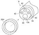
挿入部13は、先端から順に、先端部10と、湾曲部11と、可撓管部12と、が連設されて構成されている。先端部10の先端面10Aには、図5に示すように先端開口部45、観察窓42、2つの照明窓40等が配設されている。 The
2つの照明窓40、40の背面側には、図4に示すように、光源装置3からの照明光を伝送する、先端部10からユニバーサルコード18の内部に挿通するライトガイドバンドル41が設けられている。また、観察窓42の背面側には、光学系レンズ43と、イメージガイド44とが配設される。 As shown in FIG. 4, a
操作部14は、挿入部13が延出する折れ止め部15と、下部側の側部に配設される鉗子口15aと、中途部のグリップ部を構成するグリップ本体16と、上部側に設けられた湾曲操作ノブからなる湾曲操作部17と、送気送水操作部22と、吸引操作部23と、複数のスイッチから構成された主に撮像機能を操作する複数のスイッチ部24と、を有して構成されている。尚、操作部14の鉗子口15aは、先端部10の先端開口部45まで主に挿入部13内に挿通配置された挿通チャンネルの一開口部を構成している。 The
本実施形態では、図1に示すように、内視鏡2の挿入部13の先端部10側には、内視鏡位置検出装置6Aを構成する内視鏡用器具9が装着されるようになっている。 In the present embodiment, as shown in FIG. 1, an
医療機器としての内視鏡用器具9の後端側には接続ケーブル27が延設され、この接続ケーブル27の後端のコネクタ28は、位置検出装置6に着脱自在で接続される。この位置検出装置6には、内視鏡用器具9の位置センサ31に対して信号を発信する発信部8から延出されたケーブル25のコネクタ26も着脱自在で接続される。 A
この位置検出装置6により検出された先端部10の位置情報に基づく映像信号は、カラーモニタ7に出力され、このカラーモニタ7の表示面には挿入部13の先端部10の位置情報に基づく映像が表示される。 A video signal based on the position information of the
尚、発信部8は、位置センサ31に対して、例えば超音波の信号を送信したり、あるいは磁界を発生させたりする出力回路として構成したが、例えば、位置センサ31から送信された信号を受信する受信回路として構成しても良く、いずれの構成においても位置センサ31により検出された位置情報が位置検出装置6に取り込まれるようになっている。 The
次に、本実施形態に係る内視鏡用器具9の構成について図1〜図5を参照しながら説明する。
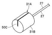
本実施形態に係る内視鏡用器具9は、図2に示すように、被検体内に挿入される弾性部材としてのチューブ体30と、このチューブ体30に接続されるとともに、被検体内に挿入される医療器具である内視鏡2の挿入部13に対して固定するための固定部32と、前記挿入部13の挿入軸O方向において前記チューブ体30内部の少なくとも1部が前記固定部32の配置と重なる領域に配置され、被検体における位置を検出するための位置検出部としての位置センサ31と、を有して構成されている。Next, the configuration of the
As shown in FIG. 2, the
チューブ体30は、例えば、シリコンやポリエチレン等の部材を用いて、少なくとも2つの内腔を有するチューブ形状に形成されたマルチルーメンチューブで構成される。チューブ体30の一つの内腔は、内視鏡2の挿入部13を挿入するための連通孔33であり、もう一つの内腔は、位置センサ31を挿通して配置すると同時にこの位置センサ31の基端部からの接続ケーブル27を基端側へと挿通するための連通孔34である。 The
固定部32は、筒状に形成されたものであって、チューブ体30の内腔33の先端側内周面に配設され、その長手方向の長さについては、挿通配置される挿入部13の先端部10の長さと略同じ位の長さを有して形成される(図4参照)。この固定部32は、例えば弾性作用を有する弾性部材を用いて構成され、その弾性作用により、挿入された内視鏡2の挿入部13を、チューブ体30の連通孔33の先端側内に固定する。 The fixing
尚、この固定部32の肉厚は、挿入部13が円滑に連通孔33内に挿通でき、また、この連通孔33内に挿入部13を効果的に固定できる寸法で構成すれば良い。さらに詳しくは、固定部32の、挿入軸O方向に直交する内径L1(図2参照)は、連通孔33に挿入される挿入部13の外径L2(図4参照)よりも小さくなるように形成される。これにより、固定部32の弾性作用、すなわち、径方向の収縮力が高まり、挿入部13を強固に固定できる。
また、固定部32は、チューブ体30の先端側に設けた構成について説明したが、さらに基端側に設けて挿入部13を固定しても良い。The thickness of the fixing
Moreover, although the fixing | fixed
位置センサ31は、挿入部13の挿入軸O方向において、チューブ体30内部の固定部32の配置と重なる領域に配置されるように、チューブ体30の連通孔34内に配設される。また、位置センサ31は、チューブ体30における連通口33の径方向に配置されると共に、挿入部13の挿入軸O方向に対して平行な位置に配置されている。位置センサ31は、チューブ体30の外周面と連通口33の内周面の間の内部に配置されている。 The
ここで、チューブ体30における位置センサ31の製造手順について説明する。
先ず、チューブ体30の先端側から、位置センサ31の基端部から延出される接続ケーブル27に結束したワイヤ(図示せず)を連通孔34内に挿通させる。Here, a manufacturing procedure of the
First, from the distal end side of the
そして、このワイヤの基端部がチューブ体30の後端部から突出すると、このワイヤの基端部を引張って徐々に接続ケーブル27を挿通させ、位置センサ31を図2に示す所定位置に配置させる。 When the proximal end portion of the wire protrudes from the rear end portion of the
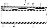
その後、チューブ体30の連通孔34の先端側の開口を、樹脂等の接着剤35により封止すると同時に位置センサ31を固定する。勿論、位置センサ31の外周に接着剤を用いて連通孔34内に固定しても良い。これにより、位置センサ31は、チューブ体30内の連通孔34内に固定される。
尚、チューブ体30における位置センサ31の製造手順は、上述した手順に限定されるものではなく、他の方法を用いて位置センサ31をチューブ体30内に配置し固定しても良い。Thereafter, the opening on the distal end side of the
In addition, the manufacturing procedure of the
このように構成された内視鏡用器具9に内視鏡2の挿入部13を挿入して固定部32により固定した状態を図4及び図5に示す。 FIGS. 4 and 5 show a state in which the
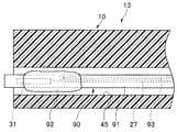
図4に示すように、挿入部13の挿入軸O方向において、チューブ体30内の固定部32の内側には、主に先端硬質部材39を備えて構成される先端部10が配置され、固定部32が配設されないチューブ体30内の連通孔33基端側には、複数の湾曲駒46を有して構成される湾曲部11及び可撓管12が配置される。 As shown in FIG. 4, in the insertion axis O direction of the
先端硬質部材39は硬質であるため、先端部10は、この固定部32の弾性作用により強固にチューブ体30内に固定される。また、先端硬質部材39内には、上述したように、照明窓40、ライトガイドバンドル41の基端側や、光学系レンズ43、イメージガイド44の基端側が配設される。 Since the distal end
このように、本実施形態の内視鏡用器具9は、固定部32により、位置センサ31を挿入部13の先端部10に対して最適な位置に配置し且つ固定して組み付けることが可能となる。勿論、固定部32による収縮力によりチューブ体30が強固に挿入部13に固定されているので、先端部10に対して位置センサ31がずれることもない。 As described above, the
本実施形態に用いられる位置センサ31(図2〜図5参照)は、5Dセンサであるが、勿論、高精度な位置情報が得られる6Dセンサであっても良い。但し、6Dセンサを用いる場合には、内視鏡2により撮像された内視鏡画像の上方向が認識できるように、6Dセンサの上方向が一致または規定の角度で固定されるのが望ましい。 The position sensor 31 (see FIGS. 2 to 5) used in the present embodiment is a 5D sensor, but of course may be a 6D sensor that can obtain highly accurate position information. However, when the 6D sensor is used, it is desirable that the upper direction of the 6D sensor is coincident or fixed at a predetermined angle so that the upper direction of the endoscopic image captured by the endoscope 2 can be recognized.
すなわち、6Dセンサは、3次元位置座標値X、Y、Z、及びオイラー角(XY平面上の横方向の角度a:azimuth、XY平面上の縦方向の角度e:elevation、及び回転角度r:roll)の6つの位置情報を検出可能な位置センサであるため、この6Dセンサの上方向(UP方向)と、内視鏡2の先端部10の観察窓42(具体的には観察窓42の奥に配置されるイメージガイド等の撮像素子)の上方向(UP方向)とを一致させて配置しなければならない。または、図6に示すように、この6Dセンサの上方向(UP方向)と、内視鏡2の先端部10の観察窓42(具体的には観察窓42の奥に配置されるイメージガイド等の撮像素子)の上方向(UP方向)がある角度で固定されなければならない。図6は、6DセンサのUP方向と先端部の観察窓のUP方向がある角度θで固定された構成を示す平面図である。 That is, the 6D sensor has three-dimensional position coordinate values X, Y, Z, and Euler angles (lateral angle a: azimuth on the XY plane, vertical angle e: elevation on the XY plane, and rotation angle r: roll) is a position sensor that can detect six pieces of position information, and therefore, the upward direction (UP direction) of this 6D sensor and the observation window 42 (specifically, the
図6に示すように、6DセンサのUP方向と、内視鏡2の先端部10の観察窓42のUP方向がある角度θで固定された場合には、この角度θ分を位置検出装置6で補正すればよいので、本実施形態においては、6Dセンサの上方向(UP方向)と、内視鏡2の先端部10の観察窓42の上方向(UP方向)とを一致させるように、容易に挿入部13に対して内視鏡用器具を組み付ける場合を例に説明する。 As shown in FIG. 6, when the UP direction of the 6D sensor and the UP direction of the
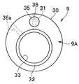
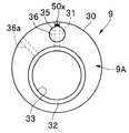
具体的には、内視鏡用器具9は、図3及び図5に示すように、チューブ体30の先端面9A上において、6Dセンサ31のUP方向U1を示す指標36を設け、さらに、この6Dセンサ31のUP方向U1と、観察窓42のUP方向U2とが一致するように挿通チャンネルの先端開口部45に合わせるための指標36aとを有して構成される。これらの指標は、チューブ体30の先端面9A上に、例えば、印刷、或いは塗料を塗布して設けられたものである。勿論これ以外の方法で、指標を設けて構成しても良い。 Specifically, as shown in FIGS. 3 and 5, the
通常、観察窓42のUP方向U2は、図5に示すように、先端部10の中心に向かう方向ではなく、斜め方向に少しずれている。このため、この観察窓42のUP方向U2と、6Dセンサ31のUP方向U1とが一致するように、挿入部13に対してチューブ体30を回転させて位置決めを行う必要がある。 Normally, the UP direction U2 of the
この場合、一般の内視鏡2において、観察窓42と、開口部45や2つの照明窓40との配置関係は固定である。このため、本実施形態の内視鏡用器具9において、前記指標36aは、先端開口部45の略中心と合わせたときに、6Dセンサ31のUP方向U1と、観察窓42のUP方向U2とが一致するように設けられている。 In this case, in the general endoscope 2, the arrangement relationship between the
このため、術者等は、内視鏡用器具9を挿入部13に組み付ける際に、指標36aの延長線(点線で示す)が先端部10の開口部45の中心を通るように指標36aと開口部45を合わせて組み付けることにより、簡単に6Dセンサ31のUP方向U1と、観察窓42のUP方向U2とを一致させることができる。これにより、6Dセンサ31による正確な位置情報を得ることができ、6Dセンサ31の精度を確保することができる。 For this reason, when the surgeon or the like attaches the
6Dセンサ31としては、例えば、図19に示すように、筒状に構成された本体31A内に複数のコイル31Bを有し、この本体31Aの基端部から接続ケーブル27が延設され、さらに、この6DセンサのUP方向を示す指標50cを先端面から外周面に掛けて設けて構成したものであっても良い。図19は本実施形態に用いられる6Dセンサの概略構成を示す斜視図である。このセンサを用いた場合、図20に示すように、チューブ体30への組み付け精度よくできるように、チューブ体30にUP方向を示す指標50xをつけてもよい。図20はチューブ体にUP方向を示す指標を設けた構成を示す平面図である。 For example, as shown in FIG. 19, the
また、6Dセンサ31を用いずに、2つの5Dセンサ31を用いて6Dセンサ31による位置情報と同等の位置情報を得ることも可能である。具体的には、図21に示すように、図2に示す実施形態の5Dセンサ31の他に、もう一方の5Dセンサ31を、他方の5Dセンサ31と対向するようにチューブ体30内に配設する。 Further, it is possible to obtain position information equivalent to the position information obtained by the
この場合、2つの5Dセンサ31は、挿入部13の挿入軸O方向において同一の位置に配設される。また、予め対向配置された5Dセンサ31間の距離を、位置検出装置6内の図示しないメモリに記憶させておき、この距離を用いて位置検出装置6により演算処理を行うことで、一方の5Dセンサ31のUP方向を求め、このUP方向を示す指標50Dを、チューブ体30の先端面9A及び外周面に設ける。勿論、前記実施形態例と同様に、この指標50Dは先端開口部45の中心と合わせるための指標であっても良い。これにより、2つの5Dセンサ31を用いた場合でも、6Dセンサ31と同様に先端部10の正確な位置情報を得ることが可能である。 In this case, the two
さらに、本実施形態では、内視鏡用器具9が装着される内視鏡2の挿入部13は複数種のものがあるので、正確な先端部10の位置情報を得るためには、装着毎に位置センサ31のキャリブレーションを行う必要がある。しかしながら、内視鏡用器具9の接続ケーブル27の後端のコネクタ28には、予め接続される内視鏡2の種類毎に応じた、位置センサ31の組み付け補正量を格納したメモリ28aが設けられており、このメモリ28aに格納された位置センサ31の組み付け補正量を用いることにより、キャリブレーションを容易にして、正しい位置と方向とを認識することも可能である。 Furthermore, in the present embodiment, since there are a plurality of types of
以上、説明したように、本実施形態によれば、位置センサ31を内視鏡挿入部13の先端部10に対して最適な位置に配置し且つ固定して組み付ける構成とすることにより、挿入部13の先端部10の正しい位置情報を得ると共に、位置センサ31の検出精度を確保することができる内視鏡用器具9の実現が可能となる。 As described above, according to the present embodiment, the
本実施形態では内視鏡を例に説明を行ったが、挿入部を有する他の医療機器、例えば、超音波内視鏡、超音波プローブや処置具でも構わない。 In the present embodiment, an endoscope has been described as an example, but other medical devices having an insertion portion, for example, an ultrasonic endoscope, an ultrasonic probe, and a treatment tool may be used.
尚、本実施形態において、6Dセンサを用いた場合に設けられる指標36aは、図5に示すように、先端開口部45の中心に合わせることにより、6Dセンサ31のUP方向U1と観察窓42のUP方向U2とを一致させるように構成したが、これに限定されるものではなく、例えば、後述する変形例1〜8に示すように構成しても良い。
このような指標36aの変形例1〜8について、図7〜図15を参照しながら説明する。In the present embodiment, the
(変形例1)
図7は、変形例1に係る指標の構成を示す図である。本実施形態に係る内視鏡用器具9は、図7に示す指標50を設けて構成しても良い。すなわち、変形例1に係る内視鏡用器具9の先端面9Aには、指標50が設けられ、この指標50の延長線(点線で示す)が観察窓42の略中心を通るように、指標50と観察窓42とを合わせたときに、6Dセンサ31のUP方向U1と、観察窓42のUP方向U2とが一致するように配設されたものである。(Modification 1)
FIG. 7 is a diagram illustrating a configuration of an index according to the first modification. The
この構成により、術者等は、内視鏡用器具9を挿入部13に組み付ける際に、指標50に観察窓42の中心が合うように合わせて組み付けることにより、簡単に6Dセンサ31のUP方向U1と、観察窓42のUP方向U2とを一致させることができる。これにより、前記実施形態と同様に6Dセンサ31による正確な位置情報を得ることができ、6Dセンサ31の検出精度を確保することができる。 With this configuration, the operator or the like can easily attach the
(変形例2)
図8は、変形例2に係る指標の構成を示す図である。本実施形態に係る内視鏡用器具9は、図8に示す複数の指標50a、50b、51aを設けて構成しても良い。すなわち、位置合わせし易いように、変形例2に係る内視鏡用器具9の先端面9Aには、複数の指標50a、50b、51aが設けられている。(Modification 2)
FIG. 8 is a diagram illustrating a configuration of an index according to the second modification. The
指標50aは、観察窓42の幅と合わせるためのもので、指標50bは、先端開口部45の幅と合わせるためのもので、2つの指標51aは、それぞれ照明窓40の幅と合わせるためのもので、具体的には、先端面9Aを、先端面9Aに直交する方向から見たときに、各指標の中心が、対応する、合わせる窓など部位の中心に最も接近するように、各指標と対応する部位を合わせるように構成されている。 The
つまり、各指標50a、50b、51aは、対応する観察窓42、先端開口部45、2つの照明窓40と合わせたときに、6Dセンサ31のUP方向U1と、観察窓42のUP方向U2とが一致するように配設されたものである。 In other words, each
この構成により、前記実施形態と同様の作用・効果が得られる他に、実施形態及び変形例1よりも指標の位置合わせを容易に行えるといった効果を得る。 According to this configuration, in addition to the same operations and effects as those of the above-described embodiment, an effect that the index can be easily aligned as compared with the embodiment and the first modification is obtained.
(変形例3)
図9は、変形例3に係る指標の構成を示す図である。本実施形態に係る内視鏡用器具9は、図9に示す指標50a、50bを設けて構成しても良い。すなわち、位置合わせし易いように、変形例3に係る内視鏡用器具9の先端面9Aには、変形例2と同じ形状の指標50a、50bが設けられているが、これらの指標50a、50bは、所定色に着色されている。例えば、指標50aには、青色が、指標50bには、赤色が付けられて、識別可能に構成されている。また、変形例2における指標の内、対向配置する指標のみが設けられている。
勿論、変形例2と同様に複数の指標50a、50b、51aを設け、これらの指標を色別に着色するように構成しても良い。また、指標を所定色に着色する他に、例えば、先端開口部、観察窓、照明窓といった名称を指標の表面或いは近傍に記載するように構成しても良い。(Modification 3)
FIG. 9 is a diagram illustrating a configuration of an index according to the third modification. The
Of course, like the second modification, a plurality of
この構成により、前記実施形態と同様の作用・効果が得られる他に、指標の識別を行うことができると共に、指標の位置合わせも容易に行えるといった効果を得る。 According to this configuration, in addition to the same operations and effects as those of the above-described embodiment, the index can be identified and the index can be easily aligned.
(変形例4)
図10は、変形例4に係る指標の構成を示す図である。本実施形態に係る内視鏡用器具9は、図10に示す指標50Aを設けて構成しても良い。すなわち、位置合わせし易いように、変形例4に係る内視鏡用器具9の先端部側面には、例えば矢印形状の指標50Aが設けられ、この指標50Aは、観察窓42の略中心と合わせたときに、すなわち、指標50Aの矢印の先端と観察窓42の中心が最も接近するように指標50Aと観察窓42を合わせたときに、6Dセンサ31のUP方向U1と、観察窓42のUP方向U2とが一致するように配設されたものである。(Modification 4)
FIG. 10 is a diagram illustrating a configuration of an index according to the fourth modification. The
尚、指標50Aは、矢印形状に構成した場合について説明したが、これに限定されるものではない。また、この矢印形状の指標50Aは、観察窓42に対応して設けられたものであるが、勿論、変形例2に示すように、先端開口部45、2つの照明窓40に対応させて設けて構成しても良い。この場合、各指標50Aは、チューブ体30の先端部外周面に設けられているので、各指標50Aの指標の内、いずれかを合わせれば良く、位置合わせを容易に行うことができる。 The
この構成により、前記実施形態と同様の作用・効果が得られる他に、チューブ体30の外周面側からでも指標の位置合わせも容易に行えるといった効果を得る。 According to this configuration, in addition to the same operations and effects as in the above-described embodiment, there is an effect that the index can be easily aligned even from the outer peripheral surface side of the
(変形例5)
図11は、変形例5に係る指標の構成を示す図である。本実施形態に係る内視鏡用器具9は、図11に示す指標50Bを設けて構成しても良い。すなわち、位置合わせし易いように、変形例5に係る内視鏡用器具9の先端部側面には、例えば名称が印された線形状の指標50Bが設けられ、この指標50Bは、観察窓42の略中心と合わせたときに、すなわち、指標50Bの延長線(点線で示す)が観察窓42の中心を通るように指標50Bと観察窓42を合わせたときに、6Dセンサ31のUP方向U1と、観察窓42のUP方向U2とが一致するように配設されたものである。(Modification 5)
FIG. 11 is a diagram illustrating a configuration of an index according to the fifth modification. The
尚、指標50Bは、チューブ体30の側面において、先端部から図示しない所定の長さ分設けられている。また、この指標50Bは、線形状に構成した場合について説明したが、これに限定されるものではなく、例えば、観察窓42の幅に合わせて線形形状の幅を広く形成しても良い。 The
また、この指標50Bは、観察窓42に対応して設けられたものであるが、勿論、変形例2に示すように、先端開口部45、2つの照明窓40に対応させて各名称と共に設けて構成しても良い。この場合、各指標50Aは、チューブ体30の先端部外周面に設けられているので、各指標50Aの指標の内、いずれかを合わせれば良く、位置合わせを容易に行うことができる。 The
この構成により、前記実施形態と同様の作用・効果が得られる他に、変形例4と同様に、チューブ体30の外周面側からでも指標の位置合わせも容易に行えるといった効果を得る。 According to this configuration, the same operation and effect as in the above embodiment can be obtained, and the effect that the index can be easily aligned even from the outer peripheral surface side of the
(変形例6)
図12は、変形例6に係る指標の構成を示す図である。本実施形態に係る内視鏡用器具9は、図12に示す指標52を設けて構成しても良い。すなわち、位置合わせし易いように、変形例6に係る内視鏡用器具9の先端部の縁部には、例えば切り欠き等により四角形状に形成された指標52が設けられ、この指標52は、観察窓42の略中心と合わせたときに、すなわち、指標52と観察窓42の中心が最も接近するように指標52と観察窓42を合わせたときに、6Dセンサ31のUP方向U1と、観察窓42のUP方向U2とが一致するように配設されたものである。(Modification 6)
FIG. 12 is a diagram illustrating a configuration of an index according to the sixth modification. The
尚、指標52は、チューブ体30の先端部縁部の一部を切り欠いて四角形状に形成した構成について説明したが、この形状に限定されるものではなく、例えば、円弧形状、或いは溝形状等に切り欠いて構成しても良い。また、挿入部13の先端部10に位置合わせして組み付けた後、この凹んでいる指標52内に接着剤等を充填して凸凹が発生しないように構成しても良い。 In addition, although the
また、この指標52は、観察窓42に対応して設けられたものであるが、勿論、変形例2に示すように、先端開口部45、2つの照明窓40に対応させて設けて構成しても良い。但し、切り欠きによる凸凹部分が増えることになるため、本変形例のようにいずれか1つに対応した1つの指標52を設けることが望ましい。
この構成により、前記実施形態と同様の作用・効果が得られる他に、切り欠きによる形状の指標52に構成したことで、指標の位置合わせを容易に行えるといった効果を得る。Further, the
According to this configuration, in addition to the same operation and effect as those of the above-described embodiment, the configuration of the
(変形例7)
図13は、変形例7に係る指標の構成を示す図である。本実施形態に係る内視鏡用器具は、図13に示す指標52Aを設けて構成しても良い。すなわち、位置合わせし易いように、変形例7に係る内視鏡用器具9の先端部外周面には、例えば切り欠き等により溝形状に形成された指標52Aが設けられ、この指標52Aは、観察窓42の略中心と合わせたときに、すなわち、指標52Aと観察窓42の中心が最も接近するように指標52Aと観察窓42を合わせたときに、6Dセンサ31のUP方向U1と、観察窓42のUP方向U2とが一致するように配設されたものである。(Modification 7)
FIG. 13 is a diagram illustrating a configuration of an index according to the seventh modification. The endoscope instrument according to the present embodiment may be configured by providing an
尚、指標52Bは、チューブ体30の側面において、先端部から図示しない所定の長さ分設けられている。また、この指標52Bは、切り欠いて溝形状に形成した構成について説明したが、この形状に限定されるものではなく、例えば、円弧形状等に切り欠いて構成しても良い。また、この場合、円弧形状に形成された指標52Bは、例えば、観察窓42の幅に合わせて円弧形状の幅を広く形成しても良い。 The indicator 52B is provided on the side surface of the
この構成により、前記実施形態と同様の作用・効果が得られる他に、変形例6と同様に切り欠きによる形状の指標52Aにしたことで、指標の位置合わせを容易に行えるといった効果を得る。 According to this configuration, in addition to the same operation and effect as the above-described embodiment, the
(変形例8)
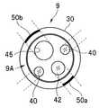
図14は、変形例8に係る指標の構成を示す図である。本実施形態に係る内視鏡用器具9は、図14に示す指標53を設けて構成しても良い。すなわち、位置合わせし易いように、変形例8に係る内視鏡用器具9の先端面9Aには、挿入部13の先端部10の先端面10Aのレイアウトと類似するように形成されたシール部材の指標53が設けられている。(Modification 8)
FIG. 14 is a diagram illustrating a configuration of an index according to the eighth modification. The
この指標53は、2つの照明窓40と位置合わせをするための透明な2つの指標部53aと、観察窓42と位置合わせするための透明な指標部53bと、先端開口部45と位置合わせをするための透明な指標部53cとを有する。 The
また、この指標53は、予め6Dセンサ31のUP方向U1と、観察窓42のUP方向U2とが一致する位置となるようにチューブ体30の先端面9A上に貼着されている。 The
すなわち、各指標部53a、53b、53cを、対応する2つの照明窓40、観察窓42、先端開口部45と合わせたときに、6Dセンサ31のUP方向U1と、観察窓42のUP方向U2とが一致することになる。 That is, when each
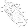
尚、指標53の各指標部53a、53b、53cは、透明となるように構成したが、図15に示すように、夫々開口させて構成しても良い。また、各指標部が透明な指標53である場合、通常、挿入部13の先端部10への組み付け後、チューブ体30から前記指標53を剥がす事になるが、図15に示すように各指標部を開口させて構成した場合、該指標53を貼着したまま使用することも可能となる。
この構成より、前記実施形態と同様の作用・効果が得られる他に、シール状の標識52を用いることにより、より簡単に指標の位置合わせを行えるといった効果を得る。In addition, although each
In addition to the effects and advantages similar to those of the above-described embodiment, this configuration provides an effect that the index can be easily aligned by using the seal-
次に、本実施形態の内視鏡用器具9に設けられた固定部32の変形例について図16〜図18を用いて説明する。
(変形例9)
図16は、変形例9に係る内視鏡用器具9の構成を示す断面図、図17は、図16に示す内視鏡用器具に挿入部を挿入して配置した状態を示す断面図、図18は、図17に示す状態の内視鏡用器具に対して固定部により固定する状態を説明する説明図である。Next, modified examples of the fixing
(Modification 9)
16 is a cross-sectional view showing a configuration of an
本変形例9に係る内視鏡用器具9は、弾性部材の固定部32に代えて、固定部を構成するC型状部材61又は紐状部材を設けるとともに、このC型状部材61又は紐状部材を取り付けるための溝部61を、チューブ体30の先端部外周面の一部に設けて構成している。 The
図16に示すように、内視鏡用器具9を構成するチューブ体30は、前記実施形態にて用いられた弾性部材の固定部32を削除して構成されている。また、チューブ体30の先端部外周面の一部には、後述する固定部としてのC型状部材61を取り付けるための溝部60が設けられている。尚、この溝部60の形状は、図16に示す四角形状に限定されるものではなく、例えばV字形状等に構成しても良い。 As shown in FIG. 16, the
この溝部60に取り付けられるC型状部材61は、図18に示すように、例えば弾性部材を用いてC型形状に形成された部材である。このC型状部材61は、その弾性作用により内径方向に収縮する収縮力を有している。 As shown in FIG. 18, the C-shaped
医療器具9を挿入部13に組み付けて固定する場合、前記実施形態と同様に挿入部13を内視鏡用器具9の連通孔33に挿入し、該先端部10の位置合わせを行い配設した後、図18に示すように、C型状部材61を、チューブ体30の溝部60に嵌め込む。さらに、もう一方の溝部60に、C型状部材61を嵌め込む。 When the
すると、これらC型状部材61の内径方向に収縮する収縮力により、図17に示すように、チューブ体30内の所定位置に挿入部13の先端部10を固定することができる。 Then, the
尚、本例では、固定部としてC型状部材61を用いてチューブ体30内に先端部10を固定したが、これに限定されるものではなく、例えば、紐状部材を溝部61に巻回して縛ることにより、チューブ体30内の所定位置に挿入部13の先端部10を固定しても良い。 In this example, the
この構成により、固定部32に代えて、C型状部材61又は紐状部材を固定部として用いた場合でも、前記実施形態と同様に、チューブ体30内の所定位置に先端部10を強固に固定することができる。 With this configuration, even when the C-shaped
(変形例10)
図22〜図25は変形例10に係る指標の構成を示す図で、図22は、固定部材を用いて長手方向を規定する指標として構成した指標の構成を示す図、図23は、長手方向を規定する目視指標として構成した指標の構成を示す図、図24及び図25は、長手方向を規定する指標の他の構成を示す図である。(Modification 10)
22 to 25 are diagrams showing the configuration of the index according to the
本実施形態に係る内視鏡用器具9は、図22〜図25に示すような、長手方向を規定する指標50E〜50Hを設けて構成してもよい。 The
チューブ体30の先端部が内視鏡先端部よりも前に出ている場合には、図22に示すように、内視鏡先端部の長手方向を規定するための付属部材である形状指標(突起)50Eを設けたり、図23に示すように視認できる指標50Fを設けることで位置検出部を内視鏡の所定の位置に固定することができる。 When the distal end portion of the
チューブ体30の先端部が内視鏡先端部よりも後ろに装着される場合には、図24および図25に示すように、内視鏡先端部の長手方向を規定するための付属部材である形状指標(位置決め部材)50G、50Hを用いることで位置検出部を内視鏡の所定の位置に固定することができる。 When the distal end portion of the
このように、端面をそろえない場合でも長手方向への位置合わせながら固定することもできる。 Thus, even when the end faces are not aligned, it can be fixed while being aligned in the longitudinal direction.
尚、多くの場合には、内視鏡先端部前面とチューブ体の端面を揃えることで、長手方向の位置が規定される。この場合には、チューブ体の端面自体が指標となるので目視指標や特別な形状による指標は必要ない。 In many cases, the position in the longitudinal direction is defined by aligning the front surface of the endoscope distal end with the end surface of the tube body. In this case, since the end surface of the tube body itself serves as an index, a visual index or an index based on a special shape is not necessary.
図26は変形例11に係る構成を示す図である。本実施形態に係る医療用器具は図26に示す指標を設けて構成しても良い。すなわち、位置あわせしやすいように、変形例11に係る医療用器具900の先端部外周面には、例えば矢印形状の指標aが設けられ、この指標aは医療用器具900が組みつけられる対象の医療装置200の湾曲方向の指標bと合わせたときに、6DセンサのUP方向U1と、医療装置の湾曲方向が一致するように配設されたものである。
尚、指標aは、矢印形状に構成した場合について説明したが、これに限定されるものではない。また、この矢印形状の指標aは、湾曲方向に対応して設けられたものであるが、湾曲方向ではなく、処置具刃先方向など医療装置の効果が及ぶ方向に対応して構成しても良い。この構成により、撮像素子のUP方向への対応に限らず、前記実施形態と同様の作用・効果が得られる。FIG. 26 is a diagram illustrating a configuration according to the eleventh modification. The medical instrument according to the present embodiment may be configured by providing an index shown in FIG. That is, in order to facilitate alignment, for example, an arrow-shaped index “a” is provided on the outer peripheral surface of the distal end portion of the
In addition, although the case where the index a is configured in an arrow shape has been described, it is not limited to this. The arrow-shaped index a is provided in correspondence with the bending direction, but may be configured not in the bending direction but in the direction in which the effect of the medical device is exerted, such as the treatment tool blade edge direction. . With this configuration, the same operation and effect as in the above-described embodiment can be obtained without being limited to the imaging element in the UP direction.
(第2の実施形態)
図27及び図28は、本発明の第2の実施形態に係り、図27は、第2の実施形態の内視鏡用器具を内視鏡挿入部の挿通チャンネルに挿通した状態を示す模式図、図28は、内視鏡用器具内の設けられた位置センサを所定位置に配置した状態でバルーンにより挿通チャンネル内に固定した状態を示す模式図である。尚、図27及び図28は、前記第1の実施形態と同様の構成要素については同一の符号を付して説明を省略し、異なる部分のみを説明する。(Second Embodiment)
27 and 28 relate to the second embodiment of the present invention, and FIG. 27 is a schematic view showing a state in which the endoscope instrument of the second embodiment is inserted into the insertion channel of the endoscope insertion portion. FIG. 28 is a schematic diagram showing a state in which the position sensor provided in the endoscope instrument is fixed in the insertion channel by a balloon in a state where the position sensor is arranged at a predetermined position. In FIGS. 27 and 28, the same components as those in the first embodiment are denoted by the same reference numerals, description thereof is omitted, and only different portions are described.
本実施形態に係る内視鏡用器具90は、チューブ体30を用いずに、内視鏡挿入部13内の挿通チャンネル45に挿通可能な医療器具であるカテーテル91として構成される。弾性部材であるこのカテーテル91の先端部内には、前記第1の実施形態と同様に位置センサ31が配設される。 The
また、カテーテル91の挿入軸方向において、位置センサ31と重なる部分の領域の表面には、バルーン92が接続されて設けられており、このバルーン92内には、カテーテル91の手元側基端部から内部に延設される送気管93の先端開口部が配設されている。
尚、このバルーン92は、位置検出装置6による図示しない送気装置の制御によって、送気管92を介して送気されて膨張し、或いは吸気されることにより収縮可能である。A
The
本実施形態の内視鏡用器具90であるカテーテル91は、図1に示す鉗子口15aを介して挿入部13内の挿通チャンネル45に挿入される。 The
そして、図27に示すように、カテーテル91の先端部、すなわち、位置センサ31が挿入部13の先端部10内の所定位置に配置されたら、送気管93を介して送気することにより、バルーン92を膨張させる。これにより、バルーン92がその膨張力により挿通チャンネル45の内周面を押圧することで、弾性のカテーテル91は挿通チャンネル45内で固定され、カテーテル91の位置センサ31を所定位置に固定することができる。
逆に、術後、カテーテル91を抜去する際には、送気管93を介して吸気することにより、バルーン92を収縮させて、固定状態を解除すれば良い。As shown in FIG. 27, when the distal end portion of the
Conversely, when the
6Dセンサを用いた場合には、前述と同様、図29に示すように、センサのUPまたは内視鏡観察窓42など内視鏡の特徴点方向示す指標50Iを設ける。この指標50Iを使って内視鏡画像のUP方向とセンサのUP方向を一致させて配置することができる。また、図29に示すように、長手方向へ規定する指標50Jも設けても良い。図29は、カテーテルに指標を設けた構成を示す図である。 When a 6D sensor is used, as shown in FIG. 29, an index 50I indicating the direction of the feature point of the endoscope such as the UP of the sensor or the
従って、第2の実施形態によれば、チューブ体30を用いずに、先端部に位置センサ31を配設したカテーテル91として内視鏡用器具90を構成し、さらに、カテーテル91を挿入部13内の挿通チャンネル45に挿通させ、且つ該挿通チャンネル45内の所定位置にバルーン92により固定した場合でも、前記第1の実施形態と同様の効果が得られる。 Therefore, according to the second embodiment, the
尚、本実施形態では、固定部は、1つのバルーン92を用いて構成したが、より強固にカテーテル91を挿通チャンネル45内に固定するために、複数のバルーン92を用いて構成しても良い。 In the present embodiment, the fixing portion is configured by using one
以上のように、上述した各実施の形態の医療機器によれば、位置センサを医療機器に対して固定して組み付け且つ最適な位置に配置する構成とすることにより、医療機器の正しい位置情報を得ると共に、位置センサの検出精度を確保することができる。 As described above, according to the medical device of each embodiment described above, the position sensor is fixed and assembled to the medical device, and the correct position information of the medical device is obtained by arranging the sensor at the optimum position. In addition, the detection accuracy of the position sensor can be ensured.
本発明は、上述した実施形態及び変形例に限定されるものではなく、本発明の要旨を変えない範囲において、種々の変更、改変等が可能である。 The present invention is not limited to the above-described embodiments and modifications, and various changes and modifications can be made without departing from the scope of the present invention.
本出願は、2011年10月31日に日本国に出願された特願2011−239360号を優先権主張の基礎として出願するものであり、上記の開示内容は、本願明細書、請求の範囲に引用されるものとする。
This application is filed on the basis of the priority claim of Japanese Patent Application No. 2011-239360 filed in Japan on October 31, 2011, and the above disclosure is included in the present specification and claims. Shall be quoted.
Claims (6)
Translated fromJapanese前記内視鏡が前記弾性部材における前記内腔に挿通された際に、挿入軸方向に直交する内径が前記内視鏡の外径よりも小さくなるように前記内腔の先端側内周面に対して筒状に配設され、前記弾性部材と前記内視鏡とを弾性作用により固定する固定部と、
被検体内における前記弾性部材の位置を検出するために、前記弾性部材の前記内腔とは異なる領域に形成された連通孔において、前記挿入軸方向に対して前記固定部の配置と重なる領域に平行に配置される位置検出部と、
を具備し、
前記固定部における収縮力に基づいて前記弾性部材が前記内視鏡に固定されることで前記位置検出部を前記連通孔に組み付けることを特徴とする医療機器。An elastic member inserted into the subject and having a lumen for holding theendoscope ;
When the endoscope is inserted into the lumen of the elastic member, the inner diameter surface perpendicular to the insertion axis direction is smaller than the outer diameter of theendoscopeon the distal side inner peripheral surface of the lumen. A fixing portion thatis arranged in a cylindrical shape and fixes the elastic member and the endoscope by an elastic action ;
In order to detect the position of the elastic member in the subject, ina communication hole formed in a region different from the lumen of the elastic member, in aregion overlapping the arrangement of the fixing portion in the insertion axis direction A position detector arranged inparallel ;
Comprising
A medical device,wherein the elastic member is fixed to the endoscope based on a contraction force in the fixing portion, and the position detection portion is assembled to thecommunication hole .
前記弾性部材と前記医療器具とを固定するために、前記溝部に対して嵌合して締め付けるC型状部材又は前記溝部に縛ることで締め付ける紐状部材であって、前記内視鏡挿入部の先端硬質部が前記溝部の近傍に配置されたときに前記C型状部材又は紐状部材を前記溝部に装着する固定部と、
被検体内における前記弾性部材の位置を検出するために、前記弾性部材の外周面及び前記内周面の間の径方向領域において、前記挿入軸方向に対して前記固定部の配置と少なくとも1部重なる領域に配置される位置検出部と、
を具備したことを特徴とする医療機器。An elastic member that is inserted into the subject and has a groove in the inner and outer peripheral surfaces for holding the endoscope;
In order to fix the elastic member and the medical instrument, a C-shaped member that is fitted and tightened to the groove, or a string-like member that is tightened by being tied to the groove, A fixing portion that attaches the C-shaped member or the string-like member to the groove portion when the distal end hard portion is disposed in the vicinity of the groove portion;
In order to detect the position of the elastic member in the subject, at least one part of the fixed portion is disposed with respect to the insertion axis direction in the radial region between the outer peripheral surface of the elastic member and the inner peripheral surface. A position detector arranged in the overlapping region;
A medical devicecharacterized by comprising:
Priority Applications (1)
| Application Number | Priority Date | Filing Date | Title |
|---|---|---|---|
| JP2013514469AJP5399589B2 (en) | 2011-10-31 | 2012-10-16 | Medical equipment |
Applications Claiming Priority (4)
| Application Number | Priority Date | Filing Date | Title |
|---|---|---|---|
| JP2011239360 | 2011-10-31 | ||
| JP2011239360 | 2011-10-31 | ||
| JP2013514469AJP5399589B2 (en) | 2011-10-31 | 2012-10-16 | Medical equipment |
| PCT/JP2012/076673WO2013065473A1 (en) | 2011-10-31 | 2012-10-16 | Medical device |
Publications (2)
| Publication Number | Publication Date |
|---|---|
| JP5399589B2true JP5399589B2 (en) | 2014-01-29 |
| JPWO2013065473A1 JPWO2013065473A1 (en) | 2015-04-02 |
Family
ID=48191830
Family Applications (1)
| Application Number | Title | Priority Date | Filing Date |
|---|---|---|---|
| JP2013514469AActiveJP5399589B2 (en) | 2011-10-31 | 2012-10-16 | Medical equipment |
Country Status (2)
| Country | Link |
|---|---|
| JP (1) | JP5399589B2 (en) |
| WO (1) | WO2013065473A1 (en) |
Cited By (2)
| Publication number | Priority date | Publication date | Assignee | Title |
|---|---|---|---|---|
| EP3108796A4 (en)* | 2014-02-21 | 2017-11-01 | Olympus Corporation | Endoscope system |
| JP2024531556A (en)* | 2021-09-07 | 2024-08-29 | シェシャオ チェン | Medical Endoscope System |
Families Citing this family (5)
| Publication number | Priority date | Publication date | Assignee | Title |
|---|---|---|---|---|
| US8182422B2 (en) | 2005-12-13 | 2012-05-22 | Avantis Medical Systems, Inc. | Endoscope having detachable imaging device and method of using |
| EP2996540A4 (en)* | 2013-05-17 | 2018-01-24 | Avantis Medical Systems, Inc. | Secondary imaging endoscopic device |
| CA3015404A1 (en)* | 2016-02-26 | 2017-08-31 | Sunnybrook Research Institute | Imaging probe with rotatable core |
| WO2018159461A1 (en)* | 2017-03-03 | 2018-09-07 | 富士フイルム株式会社 | Endoscope system, processor device, and method of operating endoscope system |
| CN110420007B (en)* | 2019-08-30 | 2024-07-19 | 常州延顺光电科技有限公司 | Insertion tube assembly for colonoscope |
Family Cites Families (4)
| Publication number | Priority date | Publication date | Assignee | Title |
|---|---|---|---|---|
| JP3506770B2 (en)* | 1994-04-21 | 2004-03-15 | オリンパス株式会社 | Endoscope position detection device |
| ES2241037T3 (en)* | 1996-02-15 | 2005-10-16 | Biosense Webster, Inc. | PRECISE DETERMINATION OF THE POSITION OF ENDOSCOPES. |
| JP2001145597A (en)* | 1999-11-22 | 2001-05-29 | Asahi Optical Co Ltd | Probe for detecting the position of the tip of an endoscope |
| JP4383115B2 (en)* | 2003-07-31 | 2009-12-16 | オリンパス株式会社 | Endoscope system |
- 2012
- 2012-10-16JPJP2013514469Apatent/JP5399589B2/enactiveActive
- 2012-10-16WOPCT/JP2012/076673patent/WO2013065473A1/enactiveApplication Filing
Cited By (3)
| Publication number | Priority date | Publication date | Assignee | Title |
|---|---|---|---|---|
| EP3108796A4 (en)* | 2014-02-21 | 2017-11-01 | Olympus Corporation | Endoscope system |
| US10419680B2 (en) | 2014-02-21 | 2019-09-17 | Olympus Corporation | Endoscope system and method of controlling endoscope system |
| JP2024531556A (en)* | 2021-09-07 | 2024-08-29 | シェシャオ チェン | Medical Endoscope System |
Also Published As
| Publication number | Publication date |
|---|---|
| WO2013065473A1 (en) | 2013-05-10 |
| JPWO2013065473A1 (en) | 2015-04-02 |
Similar Documents
| Publication | Publication Date | Title |
|---|---|---|
| JP5399589B2 (en) | Medical equipment | |
| JP5059231B2 (en) | Medical equipment | |
| EP2018112B1 (en) | Imaging catheter with position sensor | |
| US20240316317A1 (en) | Backend mechanism of a catheter control system | |
| JP2020520285A (en) | Modular endoscope | |
| US11986411B2 (en) | Devices and methods for treatment of body lumens | |
| US9050052B2 (en) | Ultrasound endoscope | |
| WO2019087550A1 (en) | Endoscopic device | |
| EP2740411A1 (en) | Ultrasonic endoscope | |
| BR112015018323B1 (en) | ENDOSCOPE THAT HAS A PROXIMAL HANDLE ASSEMBLY AND A DISTAL INSERTION SHAFT | |
| EP2942002A1 (en) | Endoscope | |
| US20070161856A1 (en) | Steering aid | |
| EP2721991B1 (en) | Endoscope | |
| US20240315783A1 (en) | Articulating guide with integral position sensor | |
| US11076749B2 (en) | Endoscope | |
| CN108926389B (en) | Medical tool puncture warning method and device | |
| JP6400221B2 (en) | Endoscope shape grasp system | |
| US11076744B2 (en) | Method of manufacturing endoscope and endoscope | |
| JP2017213316A (en) | Coil unit, and medical device | |
| JP6116465B2 (en) | Endoscope | |
| JPH10201701A (en) | Endoscope | |
| KR20180056192A (en) | The thin endoscope having alignment marker |
Legal Events
| Date | Code | Title | Description |
|---|---|---|---|
| TRDD | Decision of grant or rejection written | ||
| A01 | Written decision to grant a patent or to grant a registration (utility model) | Free format text:JAPANESE INTERMEDIATE CODE: A01 Effective date:20131008 | |
| A61 | First payment of annual fees (during grant procedure) | Free format text:JAPANESE INTERMEDIATE CODE: A61 Effective date:20131023 | |
| R151 | Written notification of patent or utility model registration | Ref document number:5399589 Country of ref document:JP Free format text:JAPANESE INTERMEDIATE CODE: R151 | |
| S111 | Request for change of ownership or part of ownership | Free format text:JAPANESE INTERMEDIATE CODE: R313111 | |
| R350 | Written notification of registration of transfer | Free format text:JAPANESE INTERMEDIATE CODE: R350 | |
| S531 | Written request for registration of change of domicile | Free format text:JAPANESE INTERMEDIATE CODE: R313531 | |
| R350 | Written notification of registration of transfer | Free format text:JAPANESE INTERMEDIATE CODE: R350 | |
| R250 | Receipt of annual fees | Free format text:JAPANESE INTERMEDIATE CODE: R250 | |
| R250 | Receipt of annual fees | Free format text:JAPANESE INTERMEDIATE CODE: R250 | |
| R250 | Receipt of annual fees | Free format text:JAPANESE INTERMEDIATE CODE: R250 | |
| R250 | Receipt of annual fees | Free format text:JAPANESE INTERMEDIATE CODE: R250 | |
| R250 | Receipt of annual fees | Free format text:JAPANESE INTERMEDIATE CODE: R250 | |
| R250 | Receipt of annual fees | Free format text:JAPANESE INTERMEDIATE CODE: R250 | |
| R250 | Receipt of annual fees | Free format text:JAPANESE INTERMEDIATE CODE: R250 |