JP5399449B2 - Pump cart for biological fluid treatment equipment - Google Patents
Pump cart for biological fluid treatment equipmentDownload PDFInfo
- Publication number
- JP5399449B2 JP5399449B2JP2011155545AJP2011155545AJP5399449B2JP 5399449 B2JP5399449 B2JP 5399449B2JP 2011155545 AJP2011155545 AJP 2011155545AJP 2011155545 AJP2011155545 AJP 2011155545AJP 5399449 B2JP5399449 B2JP 5399449B2
- Authority
- JP
- Japan
- Prior art keywords
- cart
- pump
- conduit
- supply unit
- shell
- Prior art date
- Legal status (The legal status is an assumption and is not a legal conclusion. Google has not performed a legal analysis and makes no representation as to the accuracy of the status listed.)
- Active
Links
- 239000013060biological fluidSubstances0.000titleclaimsdescription44
- 239000007788liquidSubstances0.000claimsdescription77
- 238000012545processingMethods0.000claimsdescription32
- 238000009434installationMethods0.000claimsdescription27
- 238000000034methodMethods0.000claimsdescription18
- 230000008569processEffects0.000claimsdescription18
- 238000005259measurementMethods0.000claimsdescription9
- 239000012780transparent materialSubstances0.000claimsdescription3
- 238000013519translationMethods0.000claimsdescription2
- 230000000284resting effectEffects0.000claims1
- 238000004587chromatography analysisMethods0.000description27
- 238000001914filtrationMethods0.000description25
- 238000012546transferMethods0.000description22
- 239000000047productSubstances0.000description21
- 239000002699waste materialSubstances0.000description19
- 239000000872bufferSubstances0.000description14
- 239000000706filtrateSubstances0.000description10
- HEMHJVSKTPXQMS-UHFFFAOYSA-MSodium hydroxideChemical compound[OH-].[Na+]HEMHJVSKTPXQMS-UHFFFAOYSA-M0.000description9
- 239000007853buffer solutionSubstances0.000description6
- 229910052751metalInorganic materials0.000description6
- 239000002184metalSubstances0.000description6
- 229910001220stainless steelInorganic materials0.000description6
- 239000010935stainless steelSubstances0.000description6
- 230000004308accommodationEffects0.000description5
- 238000004140cleaningMethods0.000description5
- 238000011049fillingMethods0.000description5
- 239000000203mixtureSubstances0.000description5
- 239000011550stock solutionSubstances0.000description5
- 239000011521glassSubstances0.000description4
- 239000004033plasticSubstances0.000description4
- 229920003023plasticPolymers0.000description4
- 239000000243solutionSubstances0.000description4
- 229960000074biopharmaceuticalDrugs0.000description3
- 238000012790confirmationMethods0.000description3
- 238000010828elutionMethods0.000description3
- 239000012530fluidSubstances0.000description3
- 238000002156mixingMethods0.000description3
- 239000004926polymethyl methacrylateSubstances0.000description3
- 238000000746purificationMethods0.000description3
- 239000000523sampleSubstances0.000description3
- 238000003756stirringMethods0.000description3
- 238000005303weighingMethods0.000description3
- 229930040373ParaformaldehydeNatural products0.000description2
- 230000000712assemblyEffects0.000description2
- 238000000429assemblyMethods0.000description2
- 230000015572biosynthetic processEffects0.000description2
- 238000004891communicationMethods0.000description2
- 238000009295crossflow filtrationMethods0.000description2
- 238000010586diagramMethods0.000description2
- 238000005194fractionationMethods0.000description2
- 238000003780insertionMethods0.000description2
- 230000037431insertionEffects0.000description2
- 239000012528membraneSubstances0.000description2
- 229920003229poly(methyl methacrylate)Polymers0.000description2
- 229920006324polyoxymethylenePolymers0.000description2
- 230000009467reductionEffects0.000description2
- 238000000926separation methodMethods0.000description2
- XLYOFNOQVPJJNP-UHFFFAOYSA-NwaterChemical compoundOXLYOFNOQVPJJNP-UHFFFAOYSA-N0.000description2
- 229920005372Plexiglas®Polymers0.000description1
- 102000007056Recombinant Fusion ProteinsHuman genes0.000description1
- 108010008281Recombinant Fusion ProteinsProteins0.000description1
- FAPWRFPIFSIZLT-UHFFFAOYSA-MSodium chlorideChemical compound[Na+].[Cl-]FAPWRFPIFSIZLT-UHFFFAOYSA-M0.000description1
- 241000700605VirusesSpecies0.000description1
- 239000006096absorbing agentSubstances0.000description1
- DHKHKXVYLBGOIT-UHFFFAOYSA-Nacetaldehyde Diethyl AcetalNatural productsCCOC(C)OCCDHKHKXVYLBGOIT-UHFFFAOYSA-N0.000description1
- 125000002777acetyl groupChemical class[H]C([H])([H])C(*)=O0.000description1
- 230000009286beneficial effectEffects0.000description1
- 230000008901benefitEffects0.000description1
- 210000001124body fluidAnatomy0.000description1
- 238000009529body temperature measurementMethods0.000description1
- 230000008859changeEffects0.000description1
- 238000005352clarificationMethods0.000description1
- 210000000078clawAnatomy0.000description1
- 230000003749cleanlinessEffects0.000description1
- 230000008878couplingEffects0.000description1
- 238000010168coupling processMethods0.000description1
- 238000005859coupling reactionMethods0.000description1
- 238000012258culturingMethods0.000description1
- 238000001514detection methodMethods0.000description1
- 238000011026diafiltrationMethods0.000description1
- 230000005611electricityEffects0.000description1
- 239000012149elution bufferSubstances0.000description1
- 238000007373indentationMethods0.000description1
- 238000005342ion exchangeMethods0.000description1
- 238000002955isolationMethods0.000description1
- 238000011068loading methodMethods0.000description1
- 238000004519manufacturing processMethods0.000description1
- 239000000463materialSubstances0.000description1
- 238000005457optimizationMethods0.000description1
- 239000002504physiological saline solutionSubstances0.000description1
- -1polyoxymethylenePolymers0.000description1
- 238000002360preparation methodMethods0.000description1
- 230000008929regenerationEffects0.000description1
- 239000012557regeneration bufferSubstances0.000description1
- 238000011069regeneration methodMethods0.000description1
- 238000004904shorteningMethods0.000description1
- 239000007787solidSubstances0.000description1
- 230000007704transitionEffects0.000description1
- 238000011144upstream manufacturingMethods0.000description1
- 229960005486vaccineDrugs0.000description1
- 238000011100viral filtrationMethods0.000description1
- 239000008215water for injectionSubstances0.000description1
Images


Classifications
- F—MECHANICAL ENGINEERING; LIGHTING; HEATING; WEAPONS; BLASTING
- F04—POSITIVE - DISPLACEMENT MACHINES FOR LIQUIDS; PUMPS FOR LIQUIDS OR ELASTIC FLUIDS
- F04B—POSITIVE-DISPLACEMENT MACHINES FOR LIQUIDS; PUMPS
- F04B17/00—Pumps characterised by combination with, or adaptation to, specific driving engines or motors
- F04B17/06—Mobile combinations
- B—PERFORMING OPERATIONS; TRANSPORTING
- B01—PHYSICAL OR CHEMICAL PROCESSES OR APPARATUS IN GENERAL
- B01L—CHEMICAL OR PHYSICAL LABORATORY APPARATUS FOR GENERAL USE
- B01L1/00—Enclosures; Chambers
- B01L1/52—Transportable laboratories; Field kits
- B—PERFORMING OPERATIONS; TRANSPORTING
- B01—PHYSICAL OR CHEMICAL PROCESSES OR APPARATUS IN GENERAL
- B01L—CHEMICAL OR PHYSICAL LABORATORY APPARATUS FOR GENERAL USE
- B01L9/00—Supporting devices; Holding devices
- B01L9/54—Supports specially adapted for pipettes and burettes
- B—PERFORMING OPERATIONS; TRANSPORTING
- B62—LAND VEHICLES FOR TRAVELLING OTHERWISE THAN ON RAILS
- B62B—HAND-PROPELLED VEHICLES, e.g. HAND CARTS OR PERAMBULATORS; SLEDGES
- B62B5/00—Accessories or details specially adapted for hand carts
- C—CHEMISTRY; METALLURGY
- C12—BIOCHEMISTRY; BEER; SPIRITS; WINE; VINEGAR; MICROBIOLOGY; ENZYMOLOGY; MUTATION OR GENETIC ENGINEERING
- C12M—APPARATUS FOR ENZYMOLOGY OR MICROBIOLOGY; APPARATUS FOR CULTURING MICROORGANISMS FOR PRODUCING BIOMASS, FOR GROWING CELLS OR FOR OBTAINING FERMENTATION OR METABOLIC PRODUCTS, i.e. BIOREACTORS OR FERMENTERS
- C12M1/00—Apparatus for enzymology or microbiology
- C12M1/12—Apparatus for enzymology or microbiology with sterilisation, filtration or dialysis means
- F—MECHANICAL ENGINEERING; LIGHTING; HEATING; WEAPONS; BLASTING
- F04—POSITIVE - DISPLACEMENT MACHINES FOR LIQUIDS; PUMPS FOR LIQUIDS OR ELASTIC FLUIDS
- F04B—POSITIVE-DISPLACEMENT MACHINES FOR LIQUIDS; PUMPS
- F04B23/00—Pumping installations or systems
- F—MECHANICAL ENGINEERING; LIGHTING; HEATING; WEAPONS; BLASTING
- F04—POSITIVE - DISPLACEMENT MACHINES FOR LIQUIDS; PUMPS FOR LIQUIDS OR ELASTIC FLUIDS
- F04B—POSITIVE-DISPLACEMENT MACHINES FOR LIQUIDS; PUMPS
- F04B53/00—Component parts, details or accessories not provided for in, or of interest apart from, groups F04B1/00 - F04B23/00 or F04B39/00 - F04B47/00
- F04B53/22—Arrangements for enabling ready assembly or disassembly
- B—PERFORMING OPERATIONS; TRANSPORTING
- B01—PHYSICAL OR CHEMICAL PROCESSES OR APPARATUS IN GENERAL
- B01D—SEPARATION
- B01D65/00—Accessories or auxiliary operations, in general, for separation processes or apparatus using semi-permeable membranes
- C—CHEMISTRY; METALLURGY
- C12—BIOCHEMISTRY; BEER; SPIRITS; WINE; VINEGAR; MICROBIOLOGY; ENZYMOLOGY; MUTATION OR GENETIC ENGINEERING
- C12M—APPARATUS FOR ENZYMOLOGY OR MICROBIOLOGY; APPARATUS FOR CULTURING MICROORGANISMS FOR PRODUCING BIOMASS, FOR GROWING CELLS OR FOR OBTAINING FERMENTATION OR METABOLIC PRODUCTS, i.e. BIOREACTORS OR FERMENTERS
- C12M29/00—Means for introduction, extraction or recirculation of materials, e.g. pumps
- Y—GENERAL TAGGING OF NEW TECHNOLOGICAL DEVELOPMENTS; GENERAL TAGGING OF CROSS-SECTIONAL TECHNOLOGIES SPANNING OVER SEVERAL SECTIONS OF THE IPC; TECHNICAL SUBJECTS COVERED BY FORMER USPC CROSS-REFERENCE ART COLLECTIONS [XRACs] AND DIGESTS
- Y10—TECHNICAL SUBJECTS COVERED BY FORMER USPC
- Y10T—TECHNICAL SUBJECTS COVERED BY FORMER US CLASSIFICATION
- Y10T137/00—Fluid handling
- Y10T137/6851—With casing, support, protector or static constructional installations
Landscapes
- Engineering & Computer Science (AREA)
- Chemical & Material Sciences (AREA)
- General Engineering & Computer Science (AREA)
- Mechanical Engineering (AREA)
- Health & Medical Sciences (AREA)
- Life Sciences & Earth Sciences (AREA)
- Bioinformatics & Cheminformatics (AREA)
- Clinical Laboratory Science (AREA)
- Chemical Kinetics & Catalysis (AREA)
- Wood Science & Technology (AREA)
- Biotechnology (AREA)
- Organic Chemistry (AREA)
- Zoology (AREA)
- Genetics & Genomics (AREA)
- Sustainable Development (AREA)
- Microbiology (AREA)
- Biochemistry (AREA)
- General Health & Medical Sciences (AREA)
- Medicinal Chemistry (AREA)
- Biomedical Technology (AREA)
- Combustion & Propulsion (AREA)
- Transportation (AREA)
- Apparatus Associated With Microorganisms And Enzymes (AREA)
- Handcart (AREA)
- Peptides Or Proteins (AREA)
- Details Of Reciprocating Pumps (AREA)
- Medicines Containing Antibodies Or Antigens For Use As Internal Diagnostic Agents (AREA)
- External Artificial Organs (AREA)
Description
Translated fromJapanese本発明は、生体液処理設備用ポンプカートに、具体的には、ただし限定的ではなく、モノクローナル抗体、ワクチン、または組み換えタンパク質などの生成物を得るために生物薬剤液を精製するためのポンプカートに関する。 The present invention relates to a pump cart for a biological fluid treatment facility, specifically, but not limited to, a pump cart for purifying a biopharmaceutical fluid to obtain a product such as a monoclonal antibody, a vaccine, or a recombinant protein. About.
本発明はまた、生体液処理設備にも関する。 The present invention also relates to a biological fluid processing facility.
生物薬剤液が一般にバイオリアクタ内での培養によって得られること、およびこれらがその後純度、濃度、ウイルスの不在など、必要とされる特性を実現するために処理されなければならないことは、知られている。 It is known that biopharmaceutical solutions are generally obtained by culturing in a bioreactor and that these must then be processed to achieve the required properties such as purity, concentration, absence of virus, etc. Yes.
精製は、バイオリアクタ培養物から残留物を除去するために、浄化、および場合により接線流濾過(TFF)による透析濾過および濃縮を伴うウイルス濾過などの一連の処理によって実行される。精製に関しては、クロマトグラフィ(XMO)など、その他の操作も存在する。 Purification is carried out by a series of processes such as clarification, and optionally diafiltration by tangential flow filtration (TFF) and virus filtration with concentration, to remove residues from the bioreactor culture. There are other operations for purification, such as chromatography (XMO).
精製処理は基本的に、処理済み液を収集するための容器につながる回路内の濾過操作によって実行される。 The purification process is basically performed by a filtration operation in a circuit leading to a container for collecting the processed liquid.
処理される生成物を収容するソース容器のみならず、水酸化ナトリウム(NaOH)などの洗浄液、注入用純水などのリンス液、または生理食塩水などの緩衝液を収容する容器など、液体を収容する多くの種類の容器が、回路の入口に接続されることが可能である。処理済み液を収集するための容器に加えて、洗浄、リンス、または緩衝液を収集するため、または残留物を収集するための様々なその他の容器が、回路の出口に接続されることが可能である。 Contains not only source containers that contain the product to be processed, but also liquids such as cleaning liquids such as sodium hydroxide (NaOH), rinsing liquids such as pure water for injection, or containers containing buffer solutions such as physiological saline. Many types of containers can be connected to the circuit inlet. In addition to containers for collecting processed liquids, various other containers for collecting wash, rinse, or buffer, or for collecting residues can be connected to the circuit outlet It is.
製造の脈絡では、最初の処理のための収集容器が潜在的に次の処理のためのソース容器となるなどして、最終処理が実行されるまで、液体処理は連続的に実行されることが可能である。これらの処理は従来、ステンレス鋼パイプおよびタンクまたはフィルタ筐体などのその他の部品を含む専用設備において実行され、これらは実際の処理の前後に操作を必要とし、これらの操作は、特に使用後の洗浄操作は、比較的面倒である。 In the context of manufacturing, liquid processing can be performed continuously until final processing is performed, such as the collection container for the first processing potentially becoming the source container for the next processing. Is possible. These processes are traditionally performed in dedicated equipment, including stainless steel pipes and other parts such as tanks or filter housings, which require operation before and after the actual process, and these operations are particularly important after use. The cleaning operation is relatively troublesome.
ここ数年の間、これらの処理は、液体と接触する部品が使い捨て部品となっている設備において代替的に実行されている。 Over the last few years, these processes have alternatively been performed in facilities where the parts in contact with the liquid are disposable parts.
このような使い捨て部品は、洗浄操作を回避するという利点を有するが、しかし、必要とされる安全性を提供するためには、このような部品を用いた設備の装着は、比較的複雑な選択、組み立て、および確認の作業を必要とする。 Such disposable parts have the advantage of avoiding cleaning operations, however, in order to provide the required safety, the installation of equipment with such parts is a relatively complex choice. , Requires assembly, and confirmation work.
これは特に、パイプおよびその他の回路部品(コネクタ、弁など)の数が多く、および/または操作圧力が高い場合に該当する。 This is especially true when the number of pipes and other circuit components (connectors, valves, etc.) is large and / or the operating pressure is high.
第一の態様によれば、本発明は、生体液の処理の簡単、安価、および便利な装着を可能にするポンプカートの提供を対象とする。 According to a first aspect, the present invention is directed to providing a pump cart that allows for easy, inexpensive, and convenient mounting of biological fluids.
このため、本発明は、生体液処理設備用のポンプカートに関し、この設備は搬送ネットワークカートをさらに含み、
前記ポンプカートは、第一の側面、それが前記搬送ネットワークカートに対して並置されるように構成された第二の側面、および2つの前記側面に接続する前面を有し、
前記ポンプカートは、
少なくとも1つのポンプと、
前記少なくとも1つのポンプが上に装着されるポンプ支持体と、
前記少なくとも1つのポンプを並進可動にさせ、前記ポンプ支持体を自らの上に装着する、案内部材と、をさらに含み、
前記ポンプ支持体は、前記ポンプカートの第一の側面から第二の側面に向かう方向の並進可動であり、それによって前記少なくとも1つのポンプが、実行される処理のタイプに応じて前記ポンプカート上の所定の箇所に配置される。Thus, the present invention relates to a pump cart for a biological fluid processing facility, the facility further comprising a transport network cart,
The pump cart has a first side, a second side configured to be juxtaposed with respect to the transport network cart, and a front side connected to the two side sides;
The pump cart is
At least one pump;
A pump support on which the at least one pump is mounted;
A guide member that translates the at least one pump and mounts the pump support on itself; and
The pump support is translationally movable in a direction from the first side to the second side of the pump cart so that the at least one pump is on the pump cart depending on the type of processing to be performed. Are arranged at predetermined locations.
本発明によるポンプカートが取得可能とする設備は、大部分が可撓性(「Flexware(TM)」)の使い捨て要素、とりわけ処理済み液用の収集容器、回路区間、ならびに濾過要素、および、一部は本発明によるポンプカート上、および一部は本発明によるポンプカートの第二の容器面に対して並置された搬送ネットワークカート上に配置される、恒久または再利用可能な要素(「ハードウェア」)を含むように提供される。 The equipment that can be obtained by the pump cart according to the present invention is largely disposable ("Flexware (TM)") disposable elements, in particular collection containers for processed liquids, circuit sections and filtration elements, and one A permanent or reusable element ("hardware"), partly located on a pump cart according to the invention and partly on a transport network cart juxtaposed against the second container surface of the pump cart according to the invention )).
このような設備の組み立ては、本発明によるポンプカートを含むハードウェアに、ポンプと協働するようになっている部品を含む使い捨て要素を備えるだけでおこなわれる。 The assembly of such equipment is done simply by providing the hardware including the pump cart according to the present invention with a disposable element including parts adapted to cooperate with the pump.
ポンプカート上のこれらの恒久要素の配置もまた、特に便利で効果的になるように予め決められている。 The placement of these permanent elements on the pump cart is also predetermined to be particularly convenient and effective.
このポンプの位置は、これと協働し、特に搬送ネットワークカート内(またはポンプカートに対して並置されることが可能なテーブルなど、その他のいずれかの支持体上)に設けられる、設備の主要な使い捨て要素(回路の区間または濾過要素など)の位置によって決定される。 The position of this pump cooperates with this, in particular the main installation of the equipment provided in the transport network cart (or on any other support such as a table that can be juxtaposed to the pump cart). Determined by the position of a disposable element (such as a circuit section or a filtering element).
この配置は、第一に、可撓性導管の接続を容易にすることによって、およびこれらの導管の交差を制限することによって、設備の高速装着(および分解)を保証する。 This arrangement firstly ensures fast installation (and disassembly) of the equipment by facilitating the connection of flexible conduits and by limiting the intersection of these conduits.
さらに、本発明により、ポンプが協働する要素とポンプとの接続のための第一の構成に、および処理操作の実行のための第二の構成に、ポンプを配置しやすい。 Furthermore, the present invention makes it easy to place the pump in a first configuration for connection between the pump and the elements with which the pump cooperates, and in a second configuration for performing processing operations.
この配置はまた、ポンプを搬送ネットワークカートに結合する使い捨て導管の長さを著しく短縮することを可能にする。 This arrangement also allows for a significant reduction in the length of the disposable conduit that couples the pump to the transport network cart.
特に、ポンプと搬送ネットワークカートとの間の相対位置決めは、ポンプをポンプカートに結合する可撓性導管が可能な限り短く直線状になるように、おこなわれる。 In particular, the relative positioning between the pump and the transport network cart is done so that the flexible conduit connecting the pump to the pump cart is as short and straight as possible.
この可撓性導管はまた、これが直線状でない場合に挟着のいかなる危険性も回避するために、最小曲率半径を有してもよい。 The flexible conduit may also have a minimum radius of curvature to avoid any risk of pinching if it is not straight.
使い捨て可撓性導管の長さの短縮は、導管内に存在する生体液の容積を減少させることを可能にする。これにより、例えば、処理の最後には、供給容器が空またはほぼ空であって、液体が基本的に導管内に存在するので、供給容器および濾液がそこから排出される(例えば、接線濾過による処理において)濾過要素が属するループ内で流れが生じる処理が実行される場合に、より小さい最終容積を実現することが可能になる。最終容積のこの減少は、より高い濃度のレベルを達成可能にする。 The shortening of the length of the disposable flexible conduit makes it possible to reduce the volume of biological fluid present in the conduit. Thus, for example, at the end of the process, the supply container is empty or nearly empty and the liquid is basically present in the conduit, so that the supply container and the filtrate are drained therefrom (eg by tangential filtration). A smaller final volume can be achieved if a process is performed in which a flow occurs in the loop to which the filtration element belongs. This reduction in final volume makes it possible to achieve higher levels of concentration.
さらに、移動されることが可能なポンプを有するということはまた、例えばポンプと搬送ネットワークカートとの接続など、可撓性導管の長さに関する公差を緩和することができるようにする。 Furthermore, having a pump that can be moved also allows tolerances regarding the length of the flexible conduit to be relaxed, for example, the connection between the pump and the transport network cart.
また、ポンプ支持体を通じてのポンプの移動性は、回路の要素(クロマトグラフィによる処理のためのバブルトラップおよび/または流量計など)がそのポンプと搬送ネットワークカートとの間に配置されなければならないときに、搬送ネットワークカートとそのポンプとの間の距離を適合させることができるようにする。 Also, the mobility of the pump through the pump support is such that circuit elements (such as bubble traps and / or flow meters for chromatographic processing) must be placed between the pump and the transport network cart. The distance between the transport network cart and its pump can be adapted.
このためポンプは、ポンプカートの第二の側面よりも第一の側面により近い第一の所定位置に、したがって搬送ネットワークカートに対する第一の特定距離で、または第一の側面よりも第二の側面により近い第二の所定位置に、したがって第一の距離よりも短い搬送ネットワークカートに対する第二の特定距離で、配置されてもよい。 Thus, the pump is in a first predetermined position that is closer to the first side than the second side of the pump cart, and therefore at a first specific distance relative to the transport network cart, or the second side than the first side. May be located at a second predetermined location that is closer, and therefore at a second specific distance relative to the transport network cart that is shorter than the first distance.
したがって上記により、本発明によるポンプカートが、その適合性のゆえに、様々な処理を実行する設備を備えるように適合されているという点で、非常に便利であること、が示される。 Thus, the above shows that the pump cart according to the present invention is very convenient in that it is adapted to be equipped with equipment for performing various processes because of its suitability.
本発明によるポンプカートの特に単純、便利、および経済的な特徴によれば:
前記案内部材は、2つのアームの各々にそれぞれ固定されている摺動ロッドによって離間されている前記2つのアームを含み、可動ポンプ支持体は前記ロッド上に摺動的に装着された垂直ブロックを含み、
前記垂直ブロックは、前記ロッド上の並進移動に対して前記垂直ブロックを固定するためのシステムを含み、
前記可動ポンプ支持体は、前記垂直ブロックの面上に装着されて前記少なくとも1つのポンプを受けるように構成されているレセプタクルを含み、
前記垂直ブロックの前記面には少なくとも1つの前記レセプタクルを係止する手段が設けられ、前記レセプタクルには、前記ブロックの前記面上へのその装着のための補助係止手段が設けられており、
前記垂直ブロックの前記面は、各々があるタイプの処理と関連づけられている所定の箇所に設けられたいくつかの前記係止手段を備えており、
前記レセプタクルは、前記少なくとも1つのポンプの接続ヘッドを受けるように構成された前面の切り欠きを有し、
前記可動ポンプ支持体および2つの前記アームは、前記カートの上面に設けられており、
ポンプカートは、引込位置と可動ハンドルが前記カートを移動させることができる引出位置との間で移動可能な前記ハンドルを含み、
前記可動ハンドルは取り外し可能であり、
ポンプカートは、前記上面の下、および2つの前記側面の間に位置する内部空間を含み、前記空間は、少なくとも部分的に、生体液供給ユニットを受けるように構成されており、
ポンプカートは、前記内部空間を覆うように構成されている、前記側方第一の面上の取り外し可能パネルを含み、
ポンプカートは、前記可動ポンプ支持体上に重ね置き構成において装着されているいくつかのポンプを含む。According to the particularly simple, convenient and economical features of the pump cart according to the invention:
The guide member includes the two arms separated by a slide rod fixed to each of the two arms, and the movable pump support includes a vertical block slidably mounted on the rod. Including
The vertical block includes a system for securing the vertical block against translational movement on the rod;
The movable pump support includes a receptacle mounted on a surface of the vertical block and configured to receive the at least one pump;
The surface of the vertical block is provided with means for locking at least one of the receptacles, and the receptacle is provided with auxiliary locking means for mounting the block on the surface,
The surface of the vertical block comprises a number of the locking means each provided at a predetermined location associated with a type of process;
The receptacle has a front notch configured to receive a connection head of the at least one pump;
The movable pump support and the two arms are provided on an upper surface of the cart;
The pump cart includes the handle movable between a retracted position and a retracted position where a movable handle can move the cart;
The movable handle is removable;
The pump cart includes an internal space located below the top surface and between the two side surfaces, the space being configured to receive, at least in part, a biological fluid supply unit;
The pump cart includes a removable panel on the lateral first surface configured to cover the interior space;
The pump cart includes a number of pumps mounted in a stacked configuration on the movable pump support.
第二の態様によれば、本発明はまた、生体液処理設備に関し、この設備は:
先に記載されたポンプカートと、
前記ポンプカートの前記第二の側面に対して並置された搬送ネットワークカートであって、この搬送ネットワークカートは、複数のコネクタおよび前記コネクタ間で液体を搬送するためのネットワークを有し、前記搬送ネットワークが複数の導管によって形成される、回路の一部、ならびに第一のシェルおよび前記第一のシェルに装着された第二のシェルを含み、前記第一のシェルおよび第二のシェルは前記搬送ネットワークの前記導管を形成するために協働する、プレスを含む、搬送ネットワークカートと、
前記ポンプカートの前記第一の側面に対して並置されるかまたは前記ポンプカート上に装着される生体液供給ユニットであって、前記少なくとも1つのポンプに生体液を供給するように構成されている、供給ユニットと、を含み、
前記少なくとも1つのポンプが、前記導管のコネクタに対向するように位置し、前記導管内で前記生体液を流動させるように構成されている。According to a second aspect, the invention also relates to a biological fluid treatment facility, which is:
The pump cart described above,
A transport network cart juxtaposed to the second side of the pump cart, the transport network cart comprising a plurality of connectors and a network for transporting liquid between the connectors, the transport network A portion of a circuit formed by a plurality of conduits, and a first shell and a second shell attached to the first shell, wherein the first shell and the second shell are the transport network A transport network cart including a press that cooperates to form the conduit of
A biological fluid supply unit juxtaposed to or mounted on the first side of the pump cart, wherein the biological fluid supply unit is configured to supply biological fluid to the at least one pump. A supply unit, and
The at least one pump is positioned opposite the connector of the conduit and is configured to flow the biological fluid within the conduit.
ポンプからの出口点が回路部分の導管のコネクタに対向して位置するということは、この出口点をこのコネクタに結合する使い捨て導管の長さを最適化することを可能にする。 The fact that the outlet point from the pump is located opposite the connector of the circuit part conduit makes it possible to optimize the length of the disposable conduit coupling this outlet point to this connector.
さらに、搬送ネットワークカートおよび供給ユニットは、本発明による設備の装着を容易にすることができる。 Furthermore, the transport network cart and the supply unit can facilitate the installation of the installation according to the invention.
正確には、設備の主要部品(供給ユニット、ポンプ、搬送ネットワークの導管、および濾過要素)が相互に対して最適に位置するためには、作業者が2つのカートおよび供給ユニットをまとめることで十分である。ほかにやるべきことは、使い捨て要素を設置してこれらの部品を接続することであり、こうして設備の装着は完了する。 To be precise, it is sufficient for the operator to put the two carts and the supply unit together so that the main parts of the installation (feed unit, pump, transport network conduit and filtration element) are optimally positioned relative to each other. It is. The other thing to do is install disposable elements and connect these parts, thus completing the installation of the equipment.
最後に、2つのカートおよび供給ユニット内の主要部品の配置によって設備の準備が簡素化されるのと同様に、実行可能とした処理操作の後、設備で実行される操作は特に実行しやすいが、これは、基本的に2つのカートおよび供給ユニットに備えられる使い捨て要素の廃棄の問題であって、取り外し操作は装着操作と同じくらい簡単に実行されるからである。 Finally, the operations performed on the equipment are particularly easy to perform after the processing operations made feasible, as the arrangement of the main parts in the two carts and the supply unit simplifies the equipment preparation. This is basically a matter of disposal of the disposable elements provided in the two carts and the supply unit, since the removal operation is performed as easily as the installation operation.
設備の使用にとって特に便利な好ましい特徴によれば、前記搬送ネットワークカートおよび前記供給ユニットのうちの少なくとも1つが、少なくとも部分的に前記ポンプカート内に収容されるよう構成されることである。 According to a preferred feature that is particularly convenient for the use of equipment, at least one of the transport network cart and the supply unit is configured to be at least partially housed in the pump cart.
供給ユニットおよび2つのカートについて、そのうちの少なくとも2つが一緒に収容されることが可能であり、その後分離可能であるということにより、設備(以上のように、これは2つのカートおよび供給ユニットによって形成されるモジュールを備えるモジュラー形式である)の装着が、特に回路の特定の区間の装着が容易になる。 For a supply unit and two carts, at least two of them can be housed together and then separable, so that the equipment (as above, this is formed by the two carts and the supply unit In particular, it is easy to install in specific sections of the circuit.
さらに、この少なくとも部分的な収容は、本発明による設備に必要とされる床上のフットプリントの最適化を可能にする。 Furthermore, this at least partial containment allows optimization of the footprint on the floor required for the installation according to the invention.
このフットプリントを最適化する可能性は、生物薬剤液の処理操作の場合に通常そうであるように、空間が貴重な制御された環境領域内に設備が配置されるときに、特に有利である。 The possibility of optimizing this footprint is particularly advantageous when equipment is placed in a controlled environment area where space is at a premium, as is usually the case with biopharmaceutical fluid processing operations. .
設備の、特にその供給ユニットの輸送に特に便利な好ましい特徴によれば、前記供給ユニットは、前記生体液を収容するために用意された供給容器を受けるように構成されたタンクと、前記タンクの重量を測定するための少なくとも1つの測定セルであって、前記供給ユニットが作業構成にあるときに前記少なくとも1つの測定セル上で前記タンクが載置する、少なくとも1つの測定セルと、前記供給ユニットが載置構成にあるときに前記タンクがもはや前記少なくとも1つの測定セル上に載置しないように構成された、前記タンクの重量を受けるための少なくとも1つの部材と、を含む。 According to a preferred feature of the facility, in particular particularly convenient for transporting the supply unit, the supply unit comprises a tank configured to receive a supply container prepared for containing the biological fluid; At least one measurement cell for measuring weight, wherein the tank rests on the at least one measurement cell when the supply unit is in a working configuration; and the supply unit At least one member for receiving the weight of the tank configured such that the tank no longer rests on the at least one measuring cell when in the loading configuration.
有利なことに、タンクの重量を測定するための測定セルは処理操作中に特に役立つので、タンクの重量を受けるための部材は、処理が実行されないとき、および例えば供給ユニットを輸送しているとき、そのタンクが満タンであろうが空であろうが、タンクの重量を測定するための測定セルが解放されることを可能にする。 Advantageously, the measuring cell for measuring the weight of the tank is particularly useful during processing operations, so that the member for receiving the weight of the tank is used when processing is not carried out and, for example, when transporting a supply unit Whether the tank is full or empty, it allows the measuring cell for measuring the weight of the tank to be released.
本発明の設備の使用の簡素性および利便性にとって有益である好ましい特徴によれば:
前記少なくとも1つの測定セルは、2つの板の間に介在し、そのうちの1つは前記タンクに固定され、もう一方は前記供給ユニットに固定され、前記重量受け部材は、2つの前記板の間に介在するカムによって、および2つの前記板を移動して分離するように前記カムを移動するように構成されたクランクによって、形成され、
前記供給ユニットは、測定セルが存在するのと同じ数の重量受け部材を含む。According to preferred features that are beneficial to the simplicity and convenience of use of the equipment of the present invention:
The at least one measuring cell is interposed between two plates, one of which is fixed to the tank, the other is fixed to the supply unit, and the weight receiving member is a cam interposed between the two plates. And by a crank configured to move the cam to move and separate the two plates,
The supply unit includes as many weight receivers as there are measuring cells.
設備のさらに別の特に便利な好ましい特徴によれば、前記供給ユニットは、複数の弁が設けられた第一の側面と、前記第一の側面の反対側の面であって前記ポンプカートに対向する第二の側面と、を有する。 According to yet another particularly convenient preferred feature of the installation, the supply unit comprises a first side provided with a plurality of valves and a surface opposite to the first side and facing the pump cart. And a second side.
適切である限り、供給ユニットは、供給容器が設けられたタンクを含まず、主要な機能として、例えば原液を収容する、様々な容器から来る液体のポンプへの通路を分配器の要領で、(弁によって)通行許可または遮断しなければならない。 As far as appropriate, the supply unit does not include a tank provided with a supply container, but as a main function, for example, in the manner of a distributor, with passages to liquid pumps coming from various containers containing stock solutions ( It must be permitted or blocked (by a valve).
設備の特に便利な好ましい特徴によれば、前記第二の搬送ネットワークカートは、前面を有する基部と、可動または取り外し可能ドアと、前記基部の前記前面上に配置された前記第一のシェルと、前記ドア内に配置された前記第二のシェルと、を含み、前記搬送ネットワークカートは、前記導管が形成される閉鎖ドア位置を有し、前記第二のシェルはさらに透明材料でできていて、前記ドアは少なくとも部分的に透明材料でできており、それによって前記搬送ネットワークの前記導管内の生体液の搬送を、設備の外側から見ることができる。 According to a particularly convenient preferred feature of the installation, the second transport network cart comprises a base having a front surface, a movable or removable door, the first shell disposed on the front surface of the base, The second shell disposed within the door, wherein the transport network cart has a closed door location in which the conduit is formed, and the second shell is further made of a transparent material, The door is at least partly made of a transparent material, so that the transport of biological fluid in the conduits of the transport network can be seen from outside the facility.
有利なことに、プレス内に印加される圧力に耐えるために、ドアおよび第二のシェルがそれぞれに(特に第二のシェルが)十分な厚みを有していなければならないにもかかわらず、操作者は、搬送ネットワークカートの搬送ネットワークの導管内の生体液の搬送を監視することができる。 Advantageously, the door and the second shell must each have a sufficient thickness (especially the second shell) to withstand the pressure applied in the press. A person can monitor the transport of biological fluid in the conduits of the transport network of the transport network cart.
本発明の開示は、ここで以下の添付図面を参照し、説明的および非限定的な例によって以下に与えられる、実施形態の説明とともに続けられる。 The disclosure of the present invention will now continue with the description of embodiments, given below by way of illustrative and non-limiting examples, with reference to the following accompanying drawings.
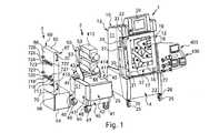
図1を参照すると、分離構成において、ネットワークカート1を搬送する第一のカート、ポンプカート2である第二のカート、および生体液供給ユニット3を含む、クロマトグラフィによって生体液を処理するための第一の設備が見られ、これはすなわち、第一のカート1が第二のカート2から離れ、供給ユニット3が第二のカート2から離れ、第二のカート2が第一のカート1と供給ユニット3との間に位置する構成である。 Referring to FIG. 1, in a separate configuration, a first cart for processing biological fluids by chromatography, including a first cart carrying a
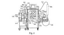
図2から図4を参照すると、収容構成における、2つのカート1および2ならびに供給ユニット3を備える同じ設備が見られ、これはすなわち、第二のカート2がその側面のうちの1つで第一のカート1に対して並置され、供給ユニット3がその側面のもう一方で第二のカート2内に部分的に収容された構成である。 With reference to FIGS. 2 to 4, the same installation with two
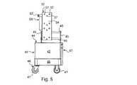
図7を参照すると、分離構成において、ネットワークカート1001を搬送する第一のカート、ポンプカート1002である第二のカート、および生体液供給のための第三のカート1003を含み、接線濾過によって生体液を処理するための第二の設備が見られ、これはすなわち、第一のカート1001が第二のカート1002から離れ、第三のカート1003が第二のカート1002から離れ、第二のカート1002が他の2つのカート1001および1003の間に位置する構成である。 Referring to FIG. 7, in a separate configuration, includes a first cart carrying a
図8から図10を参照すると、収容構成における、3つのカート1001、1002、および1003を備える同じ設備が見られ、これはすなわち、第一のカート1001が第二のカート1002の側面のうちの1つで第二のカート1002に対して並置され、第三のカートが第二のカート1002の側面のもう一方によって第二のカート1002内に部分的に収容された構成である。 Referring to FIGS. 8-10, the same equipment with three
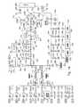
図14を参照すると、何よりもまず、クロマトグラフィによる処理の場合に、上述のカート1、2、および3上に設置された使い捨て部品を使用して生成される生体液を処理するための回路について記載がなされる。 Referring to FIG. 14, first of all, a circuit for processing biological fluids generated using disposable parts installed on the
処理される液体は、最初は先の処理からの液体で満たされたソースバッグ417内にある。このソースバッグ417は、オスコネクタ517を通じて導管13Aに接続可能である。このため、オスコネクタ517は、導管13Rを通じて供給ポンプ414に結合されたメスコネクタ617に接続される。このメスコネクタ617とこのポンプ414との間には、生成物検出器415および弁717が位置している。ポンプ414の出口には、流量計414、そしてコネクタ11Aもある。 The liquid to be processed is initially in a
緩衝液418から421の各容器は、それぞれオスコネクタ518、519、520、521を通じてその導管13Aに接続可能である。これらそれぞれのオスコネクタは、それぞれの弁718、719、720、721、および727を通じて供給ポンプ414に結合された、対応するメスコネクタ618、619、620、および621に接続される。 Each container of the
様々な容器とこの供給ポンプとの間に形成された区間は、使い捨て可撓性導管によって形成される。 The section formed between the various containers and this feed pump is formed by a disposable flexible conduit.
供給ポンプ414(ここでは使い捨てヘッドを備えるポンプ)ならびにそれぞれの弁717から721および727は、液体が導管13Aに流されることを可能にする。 A supply pump 414 (here a pump with a disposable head) and
「導管」という用語は、本明細書において、回路の2つの要素を接続する配管の一部として理解されなければならず、この部分は1つの固有の管または対照的にいくつかの管を含むことが等しく可能であり、場合によっては異なる直径を有し、単純なコネクタ(ここではその他の機能を果たさない)または高性能コネクタ(例えば圧力センサ用(または別の物理化学的値のセンサ用)使い捨てコネクタ)によって直列に接続される。 The term “conduit” is to be understood here as part of the piping connecting two elements of a circuit, which part includes one unique tube or in contrast several tubes. Can be equally possible, possibly with different diameters, simple connectors (no other function here) or high performance connectors (eg for pressure sensors (or for other physicochemical sensors)) Are connected in series by a disposable connector).
弁125Aは、導管13A内の液体の流れを許可または遮断するために、コネクタ11Aの付近の導管13A上に埋め込まれる。 The
その他の緩衝生成物はそれぞれの容器422から426内に存在し、これらは導管13Sを経由してそれぞれオスコネクタ522から526を通じて導管13Cに接続可能である。 Other buffered products are present in the
このため、それぞれのオスコネクタ522から526は、それぞれのメスコネクタ622から626に接続され、それらは導管13Sを経由してそれぞれの弁722から726を通じて供給ポンプ413に接続可能である。 Thus, each
ポンプ413の出口には、流量計403そして接続器11Cもある。 At the outlet of the
弁125Cは、導管内の液体の流れを許可または遮断するために、コネクタ11Cの付近の導管13C上に埋め込まれる。 The
処理すべき液体は一般に、ソースバッグ417から来る生成物である。 The liquid to be treated is generally the product coming from the
生成物検出器415は、導管13A内を液体が通過しているか否かの検出を可能にする。
実際、この検出器415は生成物終点、すなわち空気以外に流れる生成物がなくなったときを検出できるようにする。 In fact, this
バブルトラップ402は、メスコネクタ11Dおよび11Eに接続可能なオスコネクタ502および602を通じて、導管13Eに結合されることが可能である。
弁125Dおよび125Eは、このバブルトラップ402が供給されることまたはされないことを可能にする。 Valves 125D and 125E allow this
バブルトラップ402は、コネクタ11Gと大気に解放されるコネクタ11Fとの間の導管13F上の追加弁702をさらに含む。
フィルタ401は、メスコネクタ11Iおよび11Jにそれぞれ接続可能なオスコネクタ501および601を通じて、導管13Eに結合されることが可能である。
弁125Jおよび125Kは、液体がこのフィルタ401を通じて通過することを許可または防止することを可能にする。
弁125G、125H、および125Iは、弁125D、125E、125J、および125Kが遮断された状態で、バブルトラップ402およびフィルタ401が回避されることを可能にする。
弁125Hは、液体がバブルトラップ402まではるばる行ってそこから戻ることを可能にする、圧力制御弁でもある。
圧力センサ126は、導管13E上に装着されている。 The
第一のカート1は、具体的には伝導度センサ、温度センサ、バブル検出器、およびpHセンサを含む計装プラットフォーム405を含み、このプラットフォームはクロマトグラフィカラム406の前方に設けられている。 The
このプラットフォーム405は、上流コネクタ11Hおよび下流コネクタ11Kによって接続可能である。 The
クロマトグラフィカラム406は、オスコネクタ506および606を通じて導管13Jにおよび導管13Kに接続可能であり、これらはそれぞれのメスコネクタ11Lおよび11Mに接続可能である。
弁125L、124M、125P、125N、125R、および125Oは、クロマトグラフィカラム406内で液体の流れが形成されることを可能にする。
弁125Qは、クロマトグラフィカラム406が回避されることを可能にする。
第一のカート1は、具体的には伝導度センサ、温度センサ、pHセンサ、および紫外線センサを含む計装プラットフォーム430を含み、このプラットフォームは、収集容器407、408、410、および411ならびに廃棄物容器412の前方に設けられている。 The
これらの収集容器407、408、410、および411、ならびに廃棄物容器412は、それぞれのオスコネクタ11N、11O、11P、11Q、および11Rに接続可能なメスコネクタ507、508、510、511、および512をそれぞれ通じて導管13Kに接続可能である。 These
弁125W、125S、125T、125U、および125Vは、それぞれの収集容器および廃棄容器412への液体の流れが許可または遮断されることを可能にする。
ここでこの回路の動作が記載される。 The operation of this circuit will now be described.
カラムを用意するための緩衝液の容器418が接続され、この緩衝液は、廃棄物容器412内に収集されるまで、バブルトラップ402内へ、フィルタ401内へ、そしてクロマトグラフィカラム406内へ進入する。 A
このため、弁718、727、125A、125D、702、125E、125H、125J、125K、125L、125M、125O、125N、および125Vが開放され、その他の弁は閉鎖される。 Thus,
緩衝液はその後、(コネクタ11Hおよび11Kを通じて計装プラットフォーム405を通過して)クロマトグラフィカラム406に到達するまで、導管13A、13D、13E、13H、13I内に、その後13Eおよび13J(区間13J1を含む)内にも、進入する。緩衝液は、このカラム406を出て、廃棄物容器412内に収集されるために導管13Bに到達するまで、導管13K(区間13K1を含む)内に進入する。 The buffer is then contained in
次に、容器417から来るソース生成物のための処理サイクルが開始されるが、この生成物は、バブルトラップ402もフィルタ401も通過せずにクロマトグラフィカラム406を通過し、一部(カラムに戻されない)は廃棄物容器412内に収集される。 The processing cycle for the source product coming from
このため、弁717、125A、125G、125H、125I、125L、125M、125O、125N、および125Vが開放され、その他の弁は閉鎖される。 For this reason, the
したがって、原液は、クロマトグラフィカラム406に進入するまで、導管13R、13A、13D、13E、および13J(区間13J1によって)内を通過する。液体は、導管13K(および区間13K1)によってカラム406から出て、その後導管13Bによって廃棄物容器412内に進入する。 Thus, the stock solution passes through
生成物検出器415は、(導管13R内の大きな気泡の出現によって)容器417内にソース生成物が存在しないときを検出し、その後ポンプ414を停止させる。 The
一旦原液がクロマトグラフィカラム406内で処理されてしまうと、洗浄サイクルが開始され、ここですべての原液が、接続される容器419内に収容される緩衝液で押され(この結果、このすべての液体はカラム内に進入する)、この液体は、廃棄物容器412内に収集されるまで、バブルトラップ402、フィルタ401、計装プラットフォーム405、およびクロマトグラフィカラム406を通過する。 Once the stock solution has been processed in the
このため、弁719、727、125A、125D、702、125E、125H、125J、125K、125L、125M、125O、125N、および125Vが開放され、その他の弁は閉鎖される。 Thus,
したがって、緩衝液は、クロマトグラフィカラム406に進入するまで、導管13A、13D、13E、13H、13I内に、その後13Eおよび13J(区間13J1を含む)内を通過する。緩衝液は、カラム406を出て、導管13Bによって廃棄物容器412に到達するまで、導管13K(区間13K1を含む)を通過する。 Thus, the buffer passes through
溶出サイクル(第一の溶出ステップ)が次に開始され、ここで容器421および422内に存在する(または別の容器423から426のいずれかからの)溶出緩衝液は、第一のレベルの純度の回収された分画と同義である、分画1用の容器407内に収集されるまで、バブルトラップ402、フィルタ401、クロマトグラフィカラム406、およびプラットフォーム430を通過する。 The elution cycle (first elution step) is then started, where the elution buffer present in
このため、緩衝液を収容する容器421および422が接続され、弁721、727、722および/または723および/または724および/または725および/または726、125A、125C、125D、125E、125H、125J、125K、125L、125M、125O、125N、および125Wが開放されてその他の弁が閉鎖された状態で、ポンプ413および414によって、液体の混合が実行される。 For this purpose,
供給ポンプ413から来る液体は導管13Cを通過し、供給ポンプ414からの1つ以上の液体は、導管13D内で液体が合流するまで、導管13A内を通過し、そこでこのように混合が行われる。 Liquid coming from the
混合物はその後、クロマトグラフィカラム406に到達するまで、導管13D、13E、13H、13I、および13J(区間13J1を含む)内を通過する。 The mixture then passes through
液体は、カラム内に残ったソース生成物の一部を伴ってカラム406を離れ、導管13Kを通過して、プラットフォーム430経由で分画1用の容器407に到達する。 The liquid leaves the
次に、容器421および422からの(および/または別の容器423から426のいずれかからの)緩衝液の同じ混合物が通過する、溶出(第二のステップ)が続けられる。 Next, elution (second step) is continued, in which the same mixture of buffer from
このため、関係する容器が接続され、ポンプ413および414によって混合物が作られる。 For this purpose, the containers concerned are connected and a mixture is made by the
弁721、727、722および/または723および/または724および/または725および/または726、および弁125C、125A、125D、125E、125H、125J、125K、125L、125M、125O、125N、および125Sが開放され、その他の弁は閉鎖される。
したがって、得られた混合物は、第一のレベルより高い第二のレベルの純度の回収された分画と同義である、分画2用の容器408内に収集されるまで、バブルトラップ402、フィルタ401、計装プラットフォーム405、そしてクロマトグラフィカラム406およびプラットフォーム430を通過する。 Thus, the
供給ポンプ413から来る液体は導管13Cを通過し、供給ポンプ414からの1つ以上の液体は、導管13D内で液体が合流するまで、導管13A内を通過し、そこでこのように混合が行われる。 Liquid coming from the
混合物はその後、クロマトグラフィカラム406に到達するまで、導管13D、13E、13H、13I、および13J(区間13J1を含む)内を通過する。 The mixture then passes through
液体は、カラム内に残ったソース生成物の別の一部を伴ってカラム406を離れ、導管13Kを通過して、導管13O経由で分画2用の容器408に到達する。 The liquid leaves
収集された生成物のこの分画2に関して、pHの調整など、その他のステップが実行されてもよい。 Other steps may be performed on this
最後に、クロマトグラフィカラム406の再生サイクルにおいて、容器420からの再生緩衝生成物は、廃棄物容器412内に収集されるまで、バブルトラップ402内に、フィルタ401内に、そしてクロマトグラフィカラム406内に、底部から、進入する。 Finally, in the regeneration cycle of the
このため、容器420が接続され、弁720、727、125A、125D、125E、125H、125J、125K、125R、125O、125M、125P、および125Vが開放され、その他の弁は閉鎖される。 For this reason, the
こうして、この再生液は、コネクタ11Mにおいてクロマトグラフィカラム406に到達するまで(液体は上部からクロマトグラフィカラム内に進入しない)、導管13A、13D、13E、13H、13I、そして13E、13J、13M(液体は導管13J1内に進入しない)および導管13Kにも進入し、その後、区間13J1の末端13J2に到達するまで導管13Jに、そして導管13Bを通じて廃棄物容器412に到達するまで13L、そして13Kに進入する(液体は区間13J1および13K1に進入しない)。 Thus, this regenerated solution will reach
弁717から727とポンプ413および414との間の回路を、これらの弁ならびに弁125Bを開放してその他の弁を閉鎖することによって、および廃棄物容器400のコネクタ500をコネクタ11Bに接続することによって、(例えばソース生成物を変更する前に)排液することが、可能である。 Connect the circuit between valves 717-727 and pumps 413 and 414 by opening these valves and other valves and closing valve 125B, and connecting
上述の各ステップについて、液体を導管13Gに通過させるように、弁125Gを開放して弁125Dおよび125Eを閉鎖することによって(液体は導管13Dに進入しない)、バブルトラップ402を回避することが可能である。 For each of the above steps,
さらに、弁125Iを開放して弁125Jおよび125Kを閉鎖することによって(液体は導管13Hおよび13Iに流入しない)、フィルタ401を回避することも可能である。 It is also possible to avoid the
上述の回路を使用する設備は、図1から6を参照して次に記載される。 Equipment using the above circuit will now be described with reference to FIGS.
第一のカート1は、ほぼ台形型である。 The
第一のカート1は、第一の側面11、第一の側面11の反対側の面である第二の側面12、第一のおよび第二の側面11および12に接続する前面14、および前面14の反対側の面であって第一のおよび第二の側面11および12に接続する背面15を有する、基部10を含む。 The
第一のカート1は、プレス17およびバッグ18が設けられた回路部16をさらに含み、これは、液体用の上述のコネクタ11Aから11R、およびこれらのコネクタ11A〜Rの間の液体搬送ネットワーク19を含み、その導管13Aから13Qは、少なくとも部分的に、先に記載されている。特定の導管はバッグ18内に完全に形成され、その他のものについては1つ以上の区間のみであり、これら後者の導管のその他の区間はバッグ18の外部にあり、ここでこれらの区間は以後、導管伸長部と称される。 The
弁125Aから125Wは、シェル20内に埋め込まれ、圧力センサ126も同様である。
プレス17は、各々が剛性材料の固体ブロックで形成される、2つのシェル20および21を含む。 The
ここで、シェル20は、アセタールとも称されるポリオキシメチレン(POM)製であり、およそ175mmの厚みであって、シェル21は、ポリメチルメタクリレートまたはPlexiglas(TM)(PMMA)製であり、およそ50mmの厚みである。これらは各々がほぼ台形型である。 Here, the
シェル20は、基部10の前面14に装着される。 The
第一のカート1は、基部10に蝶番留めされたドア22をさらに含む。 The
シェル21はこのドア22に装着される。 The
第一のカート1は、ドア22が閉鎖されてシェル20を覆う閉鎖ドア位置、およびバッグ18がシェル20によってのみ担持される別の位置(図示せず)を有する。 The
この別の位置において、シェル21はシェル20から離れている。 In this other position, the
閉鎖ドア位置において、バッグ18は、2つのシェル20および21の間に挿入される。 In the closed door position, the
第一のカート1には、底部に、フィルタ401を受けるようになっている1つ以上のタンクを受けるように意図されている閉鎖ベイ23が設けられている。 The
このベイ23は、第一のカート1の前面14上に設けられた摺動パネルによって閉鎖され、このパネルは、フィルタ401を挿入および回収するように、並進において下方に、その後第一のカート1の後方に向かって移動するようになっている(図1の矢印参照)。 This
制御パネル24は、第一のカート1の前面14の上部に、操作者が使用できる高さで、配置されている。 The
この制御パネル24には、生体液処理工程を制御および操作できるようにする、グラフィカルタッチインターフェースが設けられている。 The
移動しやすくするために、第一のカート1は4つの車輪25に装着されており、そのうちの第一のカートの前面14の下の2つはブレーキ26を含み、カート1は、それぞれの側面11および12の付近で、前面14のそれぞれの反対側の面に、2つのハンドル27をさらに有する。 For ease of movement, the
第一のカート1は、その前面14に、L字型係止爪を通じてシェル20が係止される傾斜シャーシを含む。 The
支持板28は、そのシャーシに設けられた2つの固定ヘッド29の位置で、基部10のシャーシの右側に固定される。 The
2つの計装プラットフォーム405および430(実際には単一の全体的なプラットフォームをちょうど形成する)は、この支持板28に固定される。 Two
(先に記載された)処理に必要な機器は、この全体的プラットフォーム405、430に装着される。ここに示されるのは、伝導度および温度の2つのセンサ、伝導度およびpHのそれぞれの制御インターフェースに関連づけられている2つのpHセンサ、およびインターフェースに関連づけられている紫外線センサである。 The equipment required for processing (described above) is attached to this overall platform 405,430. Shown here are two sensors for conductivity and temperature, two pH sensors associated with the respective control interfaces for conductivity and pH, and an ultraviolet sensor associated with the interface.
第一のカート1の基部10は、ドア22をその閉鎖ドア位置に固定するための3つの装置30をさらに含む。これらの装置30は、空気圧ジャッキとして動作するボール固定ピン装置のものである。 The
ドア20は、ほぼ矩形の輪郭を有するステンレス鋼枠31を含み、この枠は、およそ4mmの厚みを有するガラス板32を包囲する。 The
第一のカート1は、ドア22を基部10に蝶番留めする単一の蝶番33をさらに含み、この蝶番33は、ドア22の枠31の右上コーナーに固定された第一の蝶番部34、および第一のカート1の基部2の側面11に固定された第二の蝶番部(図示せず)を含む。 The
ドア22の枠31内には、その蝶番33によって動力が供給されるドア22内にシェル21を固定するためのシステムが設けられる(図示せず)。 A system for fixing the
閉鎖ドア位置において、ドア22の第一の蝶番部34がその周囲を旋回する回転軸は、シェル20および21がその間にバッグ18を締め付けるときに、シェル20および21の間に形成された分離表面に対してずれている。 In the closed door position, the axis of rotation about which the
第一のカート1の前方に向かいこの軸ずれは、ドア22の外周においてドア22と基部10との間に側方間隙が形成されることを可能にし(図1)、これがバッグ18のコネクタ11A〜Rへのアクセスを容易にする。 This misalignment toward the front of the
シェル20および21の各々は、平坦な基準面、およびその基準面に対してくぼみ、対応する成型チャネルに対向する、複数の成型チャネルを有する。通常、これらの表面は類似の寸法を有しており、シェル20の成型チャネルの配置は、シェル21の成型チャネルのセットの鏡像である。これらの成型チャネルは、半楕円形の断面であり、互いにほぼ管状の空洞のネットワークを区切るために、チャネルが一致した状態で、互いに対して適用されてもよい。 Each of the
シェル21には、バッグ18を位置決めするための位置決め穴(図示せず)が設けられ、これらは閉鎖ドア位置においてバッグ18の位置決め開口(図示せず)に対向するように配置されている。さらに、シェル21には、閉鎖ドア位置においてドア22を位置決めするための位置決め穴(図示せず)が設けられ、これらは閉鎖ドア位置においてバッグ18の位置決め開口(図示せず)に対向するように配置されている。シェル21は、シェル20および21をまとめて固定するための穴(図示せず)をさらに含み、これらは、導管13A〜Qの形成に寄与するほとんどのチャネルが存在する箇所に位置するが、それはこれらの位置において、処理中に圧力の力が最大になるためであり、これらは閉鎖ドア位置において、バッグ18の固定開口(図示せず)に対向して配置される。 The
シェル20は、閉鎖ドア位置において、シェル20に係止されてシェル21の位置決め穴に挿入されるために、バッグ18の位置決め開口を通過するようになっている、係止鋲(図示せず)を含む。シェル20は、ドア22を位置決めするための位置決めドエル(図示せず)を含み、これらはバッグ18の開口を通過して、シェル21の位置決め穴に挿入されるようになっている。シェル20は、固定穴(図示せず)をさらに含み、これらは、導管13A〜Qの形成に寄与するほとんどの溝がある箇所に位置し、シェル20に設けられたときにバッグ18を通過する固定穴に対向するように配置され、また閉鎖ドア位置においてシェル21に対応する固定穴に対向するようにも配置されている。シェル20のこれらの固定穴には、ドア22がその閉鎖位置にあるときにシェル20および21をともに固定するため、および回路部19内にバッグ18を締め付けるための空気圧ボール固定ピン(図示せず)(空気圧ジャックとして動作)が通過する。 A locking rod (not shown) adapted to pass through the positioning opening of the
シェル20および21に加えて、第一のカート1は、ここではシェル20の後に埋め込まれた状態で(図3)、導管13A〜Q内の液体の通過を遮断または許可するように、対応する導管13A〜Qを挟持するためのアクチュエータを含むピンチ弁125Aから125W(図14)、圧力センサ、空圧分配器、ならびに制御、操作(具体的には電気セレクタ)、および例えば第二のカート2および生体液供給ユニット3と連通するための連通(具体的にはネットワークプラグ)手段など、生体液の処理に必要な機器(図示せず)を含む。 In addition to the
このため動力源は、電気(動力および制御用)および空気圧である。 Thus, the power source is electricity (for power and control) and air pressure.
バッグ18は、閉鎖外形を区切るシールによって相互に接続される2つの可撓性膜(図示せず)、および搬送ネットワーク19のコネクタ11A〜Rを含む。導管13A〜Qは、液体の通路上に形成される。 The
バブルトラップ402(図4)はここで「浮いている」ように示されるが、しかし実際には、第一のカート1上に有利に装着されている。 The bubble trap 402 (FIG. 4) is shown here as “floating”, but in practice it is advantageously mounted on the
第二のカートとも称されるポンプカート2は、ほぼ台形型であり、その内側は、生体液供給ユニット3の収容を可能にするために、中空になっている。 The
この第二のカート2は、第一の側面40、第一の側面40の反対側の面である第二の側面41、2つの側面40および41に接続する前面42、および前面42の反対側の面であって2つの側面40および41に接続する背面43を有する。 The
前面42および背面43の各々は、これらの面42および43のベースにくぼみ46を有し、これらのくぼみに46は、別のカートの足を受けるようになっている(以下の実施形態を参照)。 Each of the
これを移動しやすくするために、第二のカート2は4つの車輪に装着されており、そのうちの第一の側面40に隣接する位置にある2つは、ブレーキ48をさらに含む。 To facilitate this movement, the
第二のカート2は、内部空間を覆うために第一の側面40上の第一の可動パネル51、およびやはりこの内部空間を覆うために第二の側面41上の第二の可動パネル(図示せず)を含む。 The
第二の可動パネルの形状は、これらが完全に並置される(ほぼ収容される)ために、第一のカート1の第一の側面11のパネルの基部の形状と一致するようになっている。 The shape of the second movable panel matches the shape of the base of the panel on the
第二のカート2は、板状に示されている上面44をさらに有し、その上には、上方に、および第二のカート2の後方に向かって延在する2つのアーム45が固定されている。 The
アーム45のうちの1つは第一の側面40の付近に設けられ、アーム45のもう一方は、2つのアーム45が互いに対向する状態で、第二の側面41の付近に設けられる。 One of the
2つのアーム45は、2つのアーム45の各々にさらにしっかりとそれぞれ取り付けられている2つの摺動ロッド49(図3から6)によって離間されている。 The two
第二のカート2は、摺動ロッド49上に可動に(摺動的に)装着されているポンプ支持体50をさらに含む。 The
このポンプ支持体50はこのため、第二のカート2の第一の側面40から第二の側面41に向かう方向に、特に2つのアーム45の間で、並進可動であり、これらはこうしてポンプ支持体50の橋台を形成する。 This
ポンプ支持体50は、ロッド49上に装着された垂直ブロック52、および各々がポンプ413、414を支えるようになっている2つのステンレス鋼レセプタクル53を含む。
後壁55上で、垂直ブロック52は、特に処理を実行するための支持体50を固定するために、ロッド49上での並進移動に対してブロック52を固定するための操作ハンドル56を有する。 On the
前壁54上では、垂直ブロック52は、レセプタクル53の位置決めおよび係止のためのドエル57をさらに有する。 On the
前壁54上の所定の高さの位置に設けられた3つのドエル57は、レセプタクル53が係止されることを可能にし、ここで前壁54は、所定高さの4つの箇所を含み、そのうちの2つは、クロマトグラフィ処理のために、それぞれのポンプ413および414用の2つのレセプタクル53の係止を可能にする。 Three
ここで、所定高さの箇所は、2つのポンプ413および414を重ね置く状態で第二のカート2に装着することができるように、重ねている。 Here, the predetermined height is overlapped so that the two
さらに、垂直ブロック50は、ポンプ413および414がそれらの作動のために接続される、電力供給手段(図示せず)を有する。 Further, the
各レセプタクル53は、4辺を備えるタンクの形状になっており、底側58には、各々がレセプタクル53への係止のためにドエル57を受けるようになっている、3つの開口59が設けられている。 Each
各レセプタクル53はさらに、前側に切り欠き60を有し、これは側面および前面の各々の切り込みによって形成される(図示せず)。 Each
前側はさらに、使い捨てのそれぞれのポンプ413、414のヘッドの通路のために、円形の切り込みを有する。 The front side further has a circular cut for the head passage of each
第二のカート2はまた、引込位置(図5および図6)と、ハンドル61がその後第二のカート2をより移動させやすくなっている位置になる引出位置との間で移動可能な、ハンドル61を含む。 The
ハンドル61をその引込位置からその引出位置に移動させるためには、操作ハンドル62を緩め、その後ほぼ水平位置に到達するまでハンドル61を上方に旋回し、その後ハンドル62を再び締めるだけでよく、引出位置から引込位置に変えたい場合には、逆にすればよい。 In order to move the
ハンドル61はさらに、図1から図4に示されるように、操作ハンドル62を完全に緩めることによって取り外し可能である。 The
図4において、流量計403および404が見られ、これらはここで「浮いている」ように見えるが、しかし実際には、第二のカート2上に有利に装着されている。 In FIG. 4, flow
その背面43上で、第二のカート2は(図3)、ポンプ413および414を作動するための空気圧および電力供給手段、ならびに制御および操作手段(スイッチなど)(図示せず)をさらに含む。 On its
生体液供給ユニット3は、第二のカート2の内部空間内に収容されるように装着されるようになっている基部64を含み、この基部64は、この第二のカート2の底壁(図示せず)上で載置している。 The biological fluid supply unit 3 includes a
ユニット3は、基部64に装着された台形状の分配器ブロック65をさらに含む。 The unit 3 further includes a
分配器65は、第一の側面66、および第一の側面66の反対側の面である第二の側面67を有し、この第二の側面67は、これらが収容されているときに第二のカートに対向する。 The
ユニット3は、2つの側面66および67に接続する前面68、および前面68の反対側の面であってやはり側面66および67に接続する背面69をさらに有する。 The unit 3 further has a
先に記載された弁717から726は、第一の側面66上に、生成物検出器415とともに、設けられる。 The previously described
前面68および背面69の各々には、供給ユニット3を持ち上げ、収容されているときに供給ユニット3および第二のカート2によって形成されるアセンブリを移動させることを可能にする、2つのハンドル70が設けられている(第二のカート2のハンドル61はその後取り外される)。 Each of the
その背面69において、分配器65は(図3)、弁717から726を作動させるための空気圧および電力供給手段、ならびに制御および操作手段(スイッチなど)(図示せず)をさらに含む。 On its
図4を参照して、ここで、2つのカート1および2ならびに生体液供給ユニット3のアセンブリ、そしてクロマトグラフィ処理のための設備の特定の導管の接続の説明が、与えられる。 Referring now to FIG. 4, a description of the assembly of the two
当然ながら、アセンブリは、記載されるものとは異なる順番で作られてもよい。 Of course, the assemblies may be made in a different order than that described.
第一の段階において、少なくとも1人の操作者は、第二のカート2の第一のパネル51を取り外した後に、第二のカート2の内部空間内に基部64を収容するために、分配器65のハンドル70を通じて、手動で(または電動ウィンチの力を借りて)生体液供給ユニット3を握持する。 In the first stage, at least one operator removes the
次に、操作者は、第二のカート2と供給ユニット3との間の電気的および/または空気接続を確立するために、第二のカート2の第二のパネルを取り外す。 The operator then removes the second panel of the
次に、操作者は、ポンプ支持体50の予め決められた高さの位置において、それぞれのレセプタクル53上にポンプ413および414を取り付ける。ここで、ポンプ413は、重ねるようにしてポンプ414の上になる。 Next, the operator attaches the
操作者は、それぞれの弁717から721の1つを通じて、容器417から421の1つにポンプ414のヘッドを接続することによって、導管13Rを設置する。導管13Rがポンプ414をソース生成物容器417に結合する場合、この導管13Rは、生成物検出器415をさらに通過する。 The operator installs
操作者はこれを、まずそれぞれの弁722から727のうちの少なくとも1つを通じてポンプヘッド413に、その後容器422から426(図4には示されず)のうちの1つに接続することによって、導管13Sを設置する。 The operator connects this by first connecting it to the
次に操作者は、第二のカート2の第二の側面41が第一のカートの第一の側面11に対して並置されるまで、第二のカート2を第一のカート1に向かって移動させる。 The operator then moves the
事前に、操作者は第一のカート1のモジュールを設置しており、すなわち操作者は、当然ながらドア22を閉鎖ドア位置ではない位置に配置した後に、シェル20を基部10上に、シェル21をドア22内に、そしてバッグ18をシェル20上に配置し、その後ドア22を閉鎖ドア位置22に配置している。 In advance, the operator has installed the module of the
次に操作者は、伸長部を導管13Aに設置することによって、流量計404をポンプヘッド414に、そしてバッグ18のコネクタ11Aにも、接続する。 The operator then connects the
垂直ブロック52上のポンプ支持体50の所定高さの箇所が、ポンプ414のヘッドがバッグ18のコネクタ11Aに対向するように、および結果的に導管13Aの伸長部が実質的に直線的となるように構成されていることは、特筆すべきである。 The predetermined height of the
次に操作者は、伸長部を導管13Cに設置することによって、流量計403をポンプヘッド413に、そしてバッグ18のコネクタ11Cにも、接続する。 The operator then connects the
導管13Aおよび13Cの設置のために、ポンプ支持体50は摺動ロッド49のいずれの点に位置してもよいが、しかし伸長部を導管13Aおよび13Cに設置するのに十分な空間を有するために第一のカートから可能な限り遠くに移動させるため、所定の側方第一の箇所(高さにおける箇所に対して横方向)に位置することが好ましいことは、特筆すべきである。 For installation of the
操作者は次に、固定ハンドル56を使用して、第一のカート1から最も離れたその所定の側方第一の箇所で、ポンプ支持体50を固定する。 The operator then uses the fixed
ポンプ413および414ならびに第一のカート1の間の空間は十分なので、操作者は、第二のカート2と第一のカート1との間に介在させてバブルトラップ402を設置し、次に伸長部を導管13Fに設置することによってバッグのコネクタ11Gへのこれらのコネクタのうちの1つで、次に第一の伸長部を導管13Eに設置することによってバッグ18のコネクタ11Eへのこれらコネクタの別の1つで、そして伸長部を導管13Dに設置することによってバッグ18のコネクタ11Dへのこれらコネクタのさらに別の1つで、これを接続する。 Since the space between the
次に、操作者は、具体的にはバッグ18のコネクタ11Hと機器との間の導管13Eに第二の伸長部を、バッグ18のコネクタ11Kと機器との間の導管13Jの第一の伸長部を、そしてバッグ18のコネクタ11Mと機器との間の導管13Kの第一の伸長部を設置することによって、機器を接続する。 Next, the operator specifically places a second extension in the
操作者はまた、伸長部をそれぞれの導管13Hおよび13Iに設置することによって、バッグ18のコネクタ11Iおよび11Jにフィルタ401を接続する。 The operator also connects the
操作者はさらに、通常はバッグ18のコネクタ11Lとカラム406のコネクタ506との間の導管13Jに第二の伸長部を設置することによって床に配置されているクロマトグラフィカラム406、およびこのカラム406のコネクタ606と機器との間の導管13Kの第二の伸長部を接続する。 The operator further provides a
その他の導管(図4には示されず)、具体的には分画容器407、408、410、および411ならびに廃棄物容器412および400への導管が、操作者によって追加される。 Other conduits (not shown in FIG. 4), in particular conduits to fractionation
設備はこうして、先に記載されたクロマトグラフィ処理に向けて準備される。 The equipment is thus ready for the chromatography process described above.
図15を参照して、ここで制裁液を処理するための、そして接線濾過の場合には、先に簡単に記載されたカート1001、1002、および1003上に設置された使い捨て部品を使用して形成される、回路の説明が与えられる。 Referring to FIG. 15, here for disposal of sanitary fluid, and in the case of tangential filtration, using disposable parts installed on
通常、同じ参照番号に1000を加えたものが、類似の部品に使用される。 Usually, the same reference number plus 1000 is used for similar parts.
処理される液体は、最初は先の処理からの液体で満たされたソースバッグ1417内にある。このソースバッグ1417は、オスコネクタ1517を通じて、メスコネクタ1011Fと別のメスコネクタ1011Eとの間に延在する移送導管1013Eに接続可能であり、この移送導管1013Eはメスコネクタ1011Eを通じて移送区間に接続可能であって、これはメスコネクタ1011AからT字型分岐コネクタT1323(導管1013Bおよび1013Cの交差によって形成される)の第一の開口1323aまでの間に延在する移送導管1013Aに接続可能である。 The liquid to be processed is initially in a
この移送区間は、使い捨て可撓性導管、液体を循環させるための移送ポンプ1413(ここでは使い捨てヘッドを備えるポンプ)、および2つの弁1125Aおよび1125Iを含む。 This transfer section includes a disposable flexible conduit, a transfer pump 1413 (here a pump with a disposable head) for circulating liquid, and two
ポンプ1413の使い捨てヘッドは、液体がその内部を通過するように、第一の入口/出口点1703および第二の入口/出口点1603を有する。 The disposable head of
弁1125Aは、導管内の液体の流れを許可または遮断するために、分岐コネクタ1323の付近で導管1013A内に埋め込まれる。
移送区間はまた、圧力センサ1126A用のコネクタも含む。 The transfer section also includes a connector for the
弁1125Iは、メスコネクタ1011Fの近くで導管1013E内に埋め込まれる。 Valve 1125I is embedded in
操作者は、それぞれのメスコネクタ1011G、1011H、1011I、および1011D内に接続されてもよいそれぞれのオスコネクタ1517、1518、1519、および1515を通じて、その他のバッグ1417、1418、1419、およびフィルタ1401を導管1013Eに接続する移送導管1013Kに結合する可能性を有する。 The operator passes the
これらのバッグ1417、1418、および1419は、回路の清浄状態を管理するため、あるいは処理を実行する部品に向かってまたは収集容器に向かって処理済み液を押し出すために、それぞれ緩衝液(生理食塩水)洗浄液(水酸化ナトリウム)、およびリンス液(水)を収容し、フィルタ1401は空気フィルタである。 These
導管1013Bは2つの区間を有し、そのうちの1つは充填用(コネクタ1011Aと、導管1013Bと導管1013Aの交差点との間)であってもう1つは濾過用(コネクタ1011Nと、導管1013Bと導管1013Aの交差点との間)であり、これらの区間は分岐コネクタ1323の第二の開口1323bおよび第三の開口1323cからそれぞれ延在する。
コネクタ1011Bそして供給容器1422の入口/出口開口1500に接続する充填区間は、分岐コネクタ1323の近くに埋め込まれた弁1125Bを含む。 The filling section that connects to the connector 1011B and the inlet /
この供給容器1422は、可撓性使い捨てバッグによって形成される。 The
電磁駆動部1425によって作動されるかくはん棒1430は、内部に収容される液体を均一にするために、容器1422内に設けられる。 A
導管1013Cは、そのうちの1つがT字型分岐コネクタ1360の第一の開口1360aに接続する濾過区間を形成する2つの区間を有し、圧力センサ1126C、2つの遮断弁1125Dおよび1125E、および接線フィルタ1406用のコネクタ、ならびにその他の供給区間を含む。
導管1013Bは、コネクタ1011Nを通じて、分岐コネクタ1323の第三の開口1323cをフィルタ1406の第一の入口/出口開口に結合する。
導管1013Cは、コネクタ1011Mを通じて、フィルタ1406の第二の入口/出口開口を分岐コネクタ1360の第一の開口1360aに結合する。
圧力センサ1126Bによって行われる測定は、接線フィルタ1406の機能状態がわかるようにする。 The measurement performed by the
弁1125Cは分岐コネクタ1323の近くで導管1013B上に埋め込まれ、その一方で弁1125Eは分岐コネクタ1360の近くで導管1013C上に埋め込まれる。
供給区間および収集区間は、分岐コネクタ1360の第二の開口1360bおよび第三の開口1360cからそれぞれ延在する。 The supply section and the collection section extend from the second opening 1360b and the third opening 1360c of the
供給区間は、フローポンプ1414と開口1600との間に設けられた導管1013Lを通じて、供給容器1422の出口開口1600に接続する。これは、使い捨て可撓性導管、液体を流すためのフローポンプ1414(ここでは使い捨てヘッドを備えるポンプ)、分岐コネクタ1360の近くで導管1013C上に埋め込まれた弁1125D、および導管1013C内で直列に挿入される圧力センサ1126Cのためのコネクタを含む。 The supply section is connected to the
供給区間は、ここではポンプ1414の使い捨てヘッドを示す部分1704によって形成され、このヘッドは入口点1504および出口点1604を有する。 The supply section is here formed by a
供給区間は、弁1125Dとフローポンプ1414に接続されるコネクタ1011Cとの間に位置する導管1013Cの区間をさらに含む。 The supply section further includes a section of
収集区間はメスコネクタ1011Jに接続する。これは、導管1013H、および分岐コネクタ1360の近くで導管1013H上に埋め込まれた遮断弁1125Fのみを含む。 The collection section is connected to the
実行される操作に応じて、コネクタ1011Jは、廃棄物容器1412のオスコネクタ1511に、もしくは収集容器1408のオスコネクタ1510に、接続されてもよい。 Depending on the operation being performed,
接線濾過処理回路はまた、それぞれのコネクタ1011Oおよび1011Lを通じてフィルタ1406の出口点からそれぞれ延在する、濾液を搬送するための2つの導管1013Jおよび1013Iを含み、これらの導管1013Jおよび1013Iは、それぞれのコネクタ1011Pおよび1011Kを通じて、それぞれの収集容器1400および1412のそれぞれのオスコネクタ1512および1511に接続されている。フィルタ1406の出口で回収された濾液の容積および流量が判定されるように、流量計(図示せず)を介在させることが可能である。 The tangential filtration processing circuit also includes two
弁1125Nおよび1125Mは、フィルタ1406の近くで、それぞれの導管1013Jおよび1013I内にそれぞれ埋め込まれており、圧力センサ1126D用のコネクタは、弁1125Nとフィルタ1406との間で、導管1013J内に埋め込まれている。
圧力センサ1126Dによって行われる測定は、圧力センサ1126Bによって行われる測定とともに、接線フィルタ1406の機能状態を正確にチェックできるようにする。 The measurements made by
ここでこの回路の動作が記載される。 The operation of this circuit will now be described.
濾過および収集区間における液体のいかなる流れも防止するために、弁1125C、1125D、および1125Fが閉鎖され、その他の弁は開放される。 To prevent any flow of liquid in the filtration and collection section,
オスコネクタ1517をメスコネクタ1011Fに接続することによって、およびオスコネクタ1503をメスコネクタ1011Eに接続することによって、ソースバッグ1417が移送区間に接続される。 By connecting the
処理すべき液体は、次に移送ポンプ1413によってソースバッグ1417から吸引され、移送区間1013Aおよび充填区間1013Bを通じて供給容器1422まで搬送される。 The liquid to be processed is then drawn from the
一旦搬送が実行されてしまうと、弁1125Eおよび1125Dが開放され、処理すべき液体は、フローポンプ1414の作動によって、供給区間によって形成される副回路内を流される。接線フィルタ1406内への液体の通過の後、残余分は供給容器1422に戻り、その一方で濾液は、導管1013Jおよび1013Iを通じて排出されて廃棄物容器1400および1412内に収集される。 Once transport has been performed,
処理すべき液体をフィルタ1406内に流す操作は、液体が第一の所望濃度を達成するまで継続される。 The operation of flowing the liquid to be processed through the
この第一の濃縮ステップの後、緩衝液を収容するバッグ1423がコネクタ1523を通じてコネクタ1011Gに接続される。この緩衝液はその後、そのすべてが濾過および回収され得るように処理すべき液体を導管1013Bに向けて押し出すために、位相ポンプ1413によって移送区間1013A内に導入される。導管1013Aは次に、弁1125Aを閉鎖することによって、導管1013Bから遮断される。 After this first concentration step, a
一旦搬送が実行されてしまうと、弁1125Eおよび1125Dが再び開放され、処理すべき液体は、フローポンプ1414の作動によって、供給区間によって形成される副回路内を流される。接線フィルタ1406内への液体の通過の後、残余分は供給容器1422に戻り、その一方で濾液は、導管1013Jおよび1013Iを通じて排出されて廃棄物容器1400および1412内に収集される。 Once transport has been performed,
処理すべき液体をフィルタ1406内に流す操作は、液体が第二の所望濃度を達成するまで継続される。 The operation of flowing the liquid to be processed through the
濾過液の収集はその後、2つの連続するサブステップにおいて実行される。 Filtrate collection is then performed in two successive substeps.
第一のサブステップは、導管1013Bの区間によって形成された濾過区間内、およびフィルタ1406内に収容される、濾過液を回収することからなる。 The first sub-step consists of collecting the filtrate contained in the filtration section formed by the section of
このため、移送および濾過区間を連通させるように、およびこれらを導管1013Bの別の区間によって形成される充填区間から遮断するように、弁1125Bが閉鎖される一方で、弁1125Aが開放される。 Thus, valve 1125B is closed while
同時に、導管1013Bの区間によって形成される濾過区間と導管1013Hによって形成される収集区間とを連通させるように、およびこれらを供給区間から遮断するように、弁1125Dが閉鎖される一方で、弁1125Fおよび1125Eが開放される。 At the same time,
メスコネクタ1011Jは、収集容器1408のオスコネクタ1510に接続される。 The
収集区間(導管1013H)を通じて、緩衝液を、それによって濾過区間(導管1013Bおよび導管1013Cの一部)およびフィルタ1406内に収容される濾過液の残りを、収集容器1408に移送するために、緩衝液はその後移送ポンプ1413によって移送区間(導管1013A)内に搬送される。 Buffer is used to transfer the buffer through the collection section (
第二のサブステップは、充填(導管013Bの一部)および供給(導管1013C)区間内、ならびに供給容器1422内に収容される、濾過液を収集することからなる。 The second sub-step consists of collecting the filtrate contained in the fill (part of conduit 013B) and supply (
このため、移送(導管1013A)および充填(導管1013Bの一部)区間を連通させるように、およびこれらを濾過区間(導管1013Bおよび導管1013Cの別の部分)から遮断するように、弁1125Cが閉鎖される一方で、弁1125Bが開放される。 Thus,
同時に、供給(導管1013Cの区間)および収集(導管1013H)区間を連通させるように、およびこれらを濾過区間(導管1013Bの別の区間および導管1013Cの別の区間)から遮断するように、弁1125Eが閉鎖される一方で、弁1125Dが開放される。 At the same time,
充填区間(導管1013Bの別の区間)内に収容される濾過液を供給容器1422内に移送するために、緩衝液は次に移送ポンプ1413によって移送区間(導管1013A)内に搬送される。 In order to transfer the filtrate contained in the filling section (another section of the
フローポンプ1414は次に、この液体が、供給および収集区間を通じて、容器1422から収集容器1408にもたらされることを可能にする。 The
上述の回路を使用する設置には、図7から図13を参照して次に記載される。 Installation using the above circuit will now be described with reference to FIGS.
搬送ネットワークカート1とは対照的に、第一のカートとも称される搬送ネットワークカート1001は、バッグ18とは異なるバッグ1018を含む回路部1016を含み、このバッグ1018には、コネクタ1011Aから1011N、ならびに接線濾過による処理のため、上述の導管1013Aから1013Kを含むこれらコネクタ1011Aから1011Nの間で液体を搬送するためのネットワーク1019が、設けられている。 In contrast to the
弁1125Aから1125Nは、シェル1020内に埋め込まれており、圧力センサ1126Aから1126Dも同様である。
このため、第一のカート1001の基部1010上に固定された支持板1028は、プラットフォーム1075を通じて接線フィルタ1406を支えるのみである。 For this reason, the
第一のカート1と同様に、第一のカート1001は、透明シェル1021、およびガラス板を有する可動ドア1022を含み、シェル1021はドア1022に装着されている。 Similar to the
ポンプカート2とは対照的に、第二のカートとも称されるポンプカート1002は、図1から4のポンプ支持体50上の2つのポンプ413および414が設けられた所定高さの箇所とは異なる、ポンプ支持体1050の垂直ブロック上の所定高さの箇所に設けられた、2つのポンプ1413および1414を有する。 In contrast to the
より具体的には、ポンプ1414がポンプ1413よりも上になるように、ポンプ1413を受けるレセプタクル1053は垂直ブロック1052上の所定高さの最も低い箇所に装着され、ポンプ1414を受けるレセプタクル1053は垂直ブロック1052上の所定高さの中間箇所に装着される。 More specifically, the
生体液供給ユニット3とは対照的に、生体液供給ユニット1003は、ほぼ台形型カートの形状であり、ここでは第三のカートと称される。 In contrast to the biological fluid supply unit 3, the biological
第三のカート1003が、第二のカート1002よりもはるかに大きい地上高さを越え、実質的に第一のカート1001に近い高さを越えて延在することも、特筆すべきである。 It should also be noted that the
処理領域内のその移動を容易にするために、第三のカート1003は車輪1076に装着されており、そのうちの2つはブレーキ1077を有していて、第三のカート1003は、第一の側面1079から突起している2つのハンドル1078を有する。このカートは、回路の特定部分を受けるために中空であり、接続操作を簡素化するために、その前面1080およびその側面1079および1099において部分的に開放されている。 To facilitate its movement within the processing area, the
この第三のカート1003は:
平面パネル1082によって部分的に覆われた内部金属シャーシ1081(図11から13)と、
供給容器1422を受けるためのプラスチック供給タンク1083と、
電磁駆動部1430(図10)と、
赤外線温度プローブ(図示せず)と、
電磁駆動部1430の電気モータの速度を制御するための命令手段1084と、
タンク1083内の回路で測定された値(特に供給容器1422内の液体の温度およびタンク1083の重量)を表示するための確認手段1085と、を含む。This
An internal metal chassis 1081 (FIGS. 11 to 13) partially covered by a
A
An electromagnetic drive 1430 (FIG. 10);
An infrared temperature probe (not shown);
Command means 1084 for controlling the speed of the electric motor of the
And confirmation means 1085 for displaying the values measured in the circuit in the tank 1083 (especially the temperature of the liquid in the
タンク1083は、可撓性および使い捨て供給容器1422の開口1500および1600の通路のための楕円形開口部(図示せず)、ならびに電磁駆動部1430および温度プローブ(図示せず)と協働するためのあと2つの円形開口部(図示せず)が設けられている、円錐台形底壁1087によってその一端が伸長される、円筒形側壁1086を含む。
第一の側壁1079の箇所において、円筒形側壁1086は、供給容器1422のプラスチックタンク1083内への挿入のためのドアの形状の開口部1088(図9)を有する。 At the location of the
この開口部1088は、およそ250mmの長さおよびおよそ350mmの高さを有する実質的な長方形である。 The
第三のカート1003の内部金属シャーシ1081の底部は、フォークを形成する2つの足1089を有し、その足1089は、これらが収容されるために第二のカート1002のくぼみ1046内に挿入されるようになっている。 The bottom of the
電磁駆動部1430は、プラスチックタンク1083に直接固定されている。 The
図9に見られるように、第三のカート1003はまた、例えば、具体的には供給容器1422内の生体液をかくはんするため、および/または温度測定を行うために、設備のほかの部分から分離されたときに、この第三のカート1003が自律的に動作するように、その第一の側面1079上に、電力供給手段を含む。 As seen in FIG. 9, the
タンク1083は3つの取っ手1091を有する円形枠1090上に装着されており、各々が、例えば電動ウィンチを使用して、第三のカート1003内のタンク1083の配置および取り外しのための目1092を含む。 The
この円形枠は、タンク1083を支える円形枠1090の各取っ手1091と第三のカート1003の内部金属枠1081との間に介在する部分的に視認可能な重量計1093を通じて内部金属シャーシ1081に結合されており、この重量計1093は、タンク1083の質量を正確に判断することを可能にする。 This circular frame is coupled to the
タンク1083の重量受け部材1094は、各重量計1093の位置において、円形枠1090と内部シャーシ1081との間に介在する。 The
これらの部材1094は、カム1096に結合されたクランク1095を含み(図11から13)、このカム1096は、クランク1095が載置構成を取るときには水平位置になるようになっており、その場合には、タンク1083は重量計1093の上で載置し、カム1087もまた、操作レバー1095が作業構成にあるときには、円形枠1090を内部シャーシ1081から分離させる垂直位置になるようになっており、その場合には、枠1090、そして結果的にはタンク1083も、重量計1093上に載置していない。 These
載置構成から作業構成に推移するには、操作者は、その垂直位置1096に到達させるためにカムを回転的に駆動するようにクランク1095を旋回させるため、固定用押しボタン1097を押さなければならない。 In order to transition from the mounting configuration to the working configuration, the operator must press the fixing
ここで図10を参照して、3つのカート1001、1002、および1003のアセンブリ、ならびに接線濾過による処理のための設備に特定の導管の接続の説明が、与えられる。 Referring now to FIG. 10, an explanation of the assembly of three
当然ながら、アセンブリは、記載されるものとは異なる順番で作られてもよい。 Of course, the assemblies may be made in a different order than that described.
第一の段階において、操作者は、ポンプ支持体1050の所定高さの箇所で、ポンプ1413および1414をそれぞれのレセプタクル1053に設置する。ここでポンプ1414はポンプ1413よりも上方にあり、これらのポンプは重ねてある。 In the first stage, the operator installs the
次に、操作者は、アーム1045に当接するまで、第二のカート1002の第二の側面1041に向かってポンプ支持体1050を完全に摺動させる。 The operator then completely slides the
次に、操作者は、第二のカート1002のそれぞれのくぼみ1046内にその足1089を収容するために、ハンドル1078を通じて第三のカート1003を握持する。 Next, the operator grips the
次に、操作者は、第二のカートの第二の側面1041が第一のカートの第一の側面1011に対して並置されるまで、第二のカート1002および第三のカート1003によって形成されるアセンブリを第一のカート1001に向かって移動させる。 The operator is then formed by the
事前に、操作者は第一のカート1001のモジュールを設置しており、すなわち操作者は、当然ながらドア1022を閉鎖ドア位置ではない位置に配置した後に、シェル1020を基部1010上に、シェル1021をドア1022上に、そしてバッグ1018をシェル1020上に配置し、その後ドア1022を閉鎖ドア位置1022に配置している。 In advance, the operator has installed the module of the
ポンプ支持体1050の垂直ブロック1052上の所定高さの箇所が、ポンプ1414のヘッドがコネクタ1011Cに対向するように、そして結果的に導管1013Cがポンプ1414と第一のカート1001のバッグ1018における導管1013Cの残りの部分との間で実質的に直線的となるように構成されていることは、特筆すべきである。 A predetermined height point on the
操作者はその後、導管1013Aの伸長部を設置することによって、ポンプ1413をバッグ1018のコネクタ11Aに接続する。 The operator then connects
導管1013Cおよび1013Aの設置について、ポンプ支持体1050が第一のカート1001に可能な限り近い所定の側方箇所にあり、したがって第二のカート1002の第二の側面1041の付近で摺動ロッド1049上に位置していることは、特筆すべきである。 For installation of
操作者は次に、固定ハンドル1056を使用して、第一のカート1001に最も近いその所定の側方箇所に、ポンプ支持体1050を固定する。 The operator then uses the fixed
操作者は、ポンプ1413のヘッドをバッグ1018のコネクタ11Eに接続することによって、導管1013Kを設置する。 The operator installs the
操作者は、ポンプ1414のヘッドをタンク1083内に位置する供給容器1422に接続することによって、導管1013Lを設置する。 The operator installs
操作者はその後、その供給容器1422とバッグ1018のコネクタ11Bとの間に導管1013Bの伸長部を設置する。 The operator then installs an extension of
操作者は次に、バッグ1018のコネクタ1011Lとフィルタ1406との間に導管1013Iの伸長部を、バッグ1018のコネクタ1011Nとこのフィルタ1406との間に導管1013Cの伸長部を、バッグ1018のコネクタ1011Mとこのフィルタ1406との間に導管1013Bの伸長部を、そして最後にコネクタ1011Qとこのフィルタ1406との間に導管1013Jの伸長部を設置することによって、4つの入口/出口を通じて接線フィルタ1406を接続する。 The operator then places an extension of conduit 1013I between connector 1011L of
その他の導管(図10には示されず)、具体的にはそれぞれ原液、緩衝液、洗浄液、リンス液、収集および廃棄物容器1410、1423、1418、1419、1408、1400、および1412に、そしてフィルタ1401につながる導管が、操作者によって追加される。 Other conduits (not shown in FIG. 10), specifically in stock solution, buffer solution, wash solution, rinse solution, collection and
設置はこのようにして、先に記載された接線濾過処理に向けて準備される。 The installation is thus prepared for the tangential filtration process described above.
図示されない変形例において:
クロマトグラフィ処理設備は、ポンプと流量計との間に安全圧力センサをさらに含み、
クロマトグラフィ処理設備は、いかなる流量計および/またはいかなるバブルトラップおよび/またはいかなるフィルタも含まず、
クロマトグラフィカラムは、イオン交換カラムまたは膜吸収材に置き換えられ、
第一の設備の供給ユニットは車輪装着型であり、
第一の設備の計装プラットフォームは、プレスに、したがって第一のカートの傾斜シャーシに、平行に装着されるのではなく垂直に装着され、
第二の設備の第三のカートの接線フィルタは、処理すべき生体液の容積に応じて、より大きいサイズまたはより小さいサイズであり、その場合には、タンクは適切な容積を有し(具体的には50リットル、100リットル、または200リットル)、
第二の設備の第三のカートのタンクは二重外装を有し、外側はステンレス鋼で内側はプラスチック、またはその逆、または両方ともステンレス鋼であり、
第二の設備の第三のカートのタンクは、冷却および/または加熱され、
タンクは、バッグの導入用の開口部の箇所にガラスが嵌め込まれたドアを含み、
第二の設備の第三のカートのタンクの重量受け部材は、空気圧式、機械的、油圧式、または電気的制御および操作手段を通じて、中央集約的に制御され、
タンクは3つより多いかまたは少ない重量計の上で載置し、
重量計は、その中の容積を判断するために、タンク内の液体のレベルを検出するためのレーダープローブに置き換えられる。In a variant not shown:
The chromatography facility further includes a safety pressure sensor between the pump and the flow meter,
The chromatography facility does not include any flow meter and / or any bubble trap and / or any filter,
Chromatographic columns are replaced with ion exchange columns or membrane absorbers,
The supply unit of the first equipment is wheel-mounted,
The instrumentation platform of the first equipment is mounted vertically, rather than mounted in parallel, on the press and thus on the tilted chassis of the first cart,
The tangential filter of the third cart of the second equipment is larger or smaller depending on the volume of biological fluid to be processed, in which case the tank has the appropriate volume (specifically 50 liters, 100 liters, or 200 liters)
The third cart tank of the second facility has a double exterior, the outside is stainless steel and the inside is plastic, or vice versa, or both are stainless steel,
The tank of the third cart of the second facility is cooled and / or heated,
The tank includes a door fitted with glass at the opening for introducing the bag,
The weight receiving member of the third cart tank of the second facility is centrally controlled through pneumatic, mechanical, hydraulic, or electrical control and operating means,
The tank is placed on more or less than three weigh scales,
The weigh scale is replaced with a radar probe to detect the level of liquid in the tank to determine the volume therein.
図示されないさらに別の変形例において、タンクは、第三のカートの側面と平行な面内に位置するU字型のブラケット上に旋回可能に装着され、その末端は内部金属シャーシに固定されている。タンクの円筒形側面の自由端に固定されたハンドルは、動作位置と設置位置との間で、前面に対して垂直な軸を中心に容易に旋回できるようにする。軸の付近でブラケットの直立材の各々に設けられているピンは、所望の位置に固定するために、または対照的に、自由に回転させるために、タンクの円筒形側壁に固定された2つのディスクと協働するようになっている。固定は、各ピンの末端に位置する金属ロッドの対応するディスクの孔への挿入によって実現される。反対に、タンクを自由に回転させるためには、ロッドをディスクから出させるために、各ピンを引くだけでよい。その動作位置において、タンクは、その円錐台形底壁が地面に向けられるように、直立している、供給容器はタンク内に設けられており、その開口はその底壁から地面に向かって突起している。この設置位置において、タンクは横になり、その円筒形側壁の自由末端は、第三のカートの側面の開口部に対向するように配置される。この設置位置は、使用済み供給容器の取り外しおよび新品の設置を操作者にとって容易にし、この供給容器は、その場合には、アクセスドア1088を含むタンク1083とは対照的に、タンク上方の開口部によって設置される。設備を動作させる際に、およびタンクがその動作位置に配置された後に、ピンは、濾過工程の期間にわたってタンクをこの位置に固定するようになっている。一旦工程が終了すると、このピンは、自由に旋回できるようにタンクを開放するために、取り外される。 In yet another variant, not shown, the tank is pivotally mounted on a U-shaped bracket located in a plane parallel to the side of the third cart, the end of which is fixed to the internal metal chassis. . A handle fixed to the free end of the cylindrical side of the tank allows for easy pivoting about an axis perpendicular to the front surface between the operating position and the installation position. A pin on each of the bracket uprights in the vicinity of the shaft has two pins fixed to the cylindrical side wall of the tank for fixing in the desired position or, in contrast, for free rotation. It comes to cooperate with the disc. Fixing is achieved by insertion of a metal rod located at the end of each pin into the corresponding disc hole. Conversely, in order to rotate the tank freely, it is only necessary to pull each pin in order to move the rod out of the disk. In its operating position, the tank stands upright so that its frustoconical bottom wall faces the ground, the supply container is provided in the tank, and its opening projects from its bottom wall towards the ground. ing. In this installed position, the tank lies down and its free end on its cylindrical side wall is arranged to face the opening on the side of the third cart. This installation position makes it easier for the operator to remove the used supply container and install a new one, which in this case is the opening above the tank, as opposed to the
図示されないさらに別の変形例において、タンクは、旋回のための補助を用いてまたは用いずに、先に記載されたようなやり方で旋回可能に装着される。このタンクの旋回の補助は、ラックによるシステムまたはガススプリングによって実行される。 In yet another variant, not shown, the tank is pivotably mounted in the manner described above with or without the aid for pivoting. This assistance in turning the tank is performed by a rack system or a gas spring.
図示されない別の変形例において、第一のおよび第二のカートならびに生体液供給ユニットは、全量濾過方式によって、処理用設備を装備するようになっている。 In another variant, not shown, the first and second carts and the biological fluid supply unit are equipped with processing equipment by a total volume filtration system.
本発明が記載および提示された例に限定されないことは、より一般的に特筆すべきである。 It should be noted more generally that the present invention is not limited to the examples described and presented.
1、1001 搬送ネットワークカート
2、1002 ポンプカート
3 生体液供給ユニット
10、64、1010 基部
11、40、66、1011、1079 第一の側面
11A〜R、500 コネクタ
12、41、67、1041、1099 第二の側面
13A〜S 導管
14、42、68、1080 前面
15、43、69 背面
16、1016 回路部
17 プレス
18、1018 バッグ
19 搬送ネットワーク
20、21、1020、1021 シェル
22、1022 ドア
23 閉鎖ベイ
24 制御パネル
25、47、1076 車輪
26 ブレーキ
27、61、70、1078 ハンドル
28 支持板
29 固定ヘッド
30 装置
31 ステンレス鋼枠
32 ガラス板
33 蝶番
34 第一の蝶番
44 上面
45 アーム
46、1046 くぼみ
48 ブレーキ
49、1049 摺動ロッド
50、1050 ポンプ支持体
51 第一の可動パネル
52 垂直ブロック
53 レセプタクル
54 前壁
55 後壁
56、62 操作ハンドル
57 ドエル
58 底側
59、1600 開口
60 切り欠き
65 分配器
125A〜W、702、717〜727、1125A〜N 弁
126、1126A〜D 圧力センサ
400、412 廃棄物容器
401、1401 フィルタ
402 バブルトラップ
403、404 流量計
405、430 計装プラットフォーム
406 クロマトグラフィカラム
407、408、410、411 分画容器
413、414 供給ポンプ
415 生成物検出器
417、1417 ソースバッグ
417〜426 緩衝液容器
501、502、506、517〜526、601、602、606、1501、1503、1510、1511、1512、1515、1517、1518、1519、1523 オスコネクタ
507、508、510、511、512、617〜626、1011A〜P メスコネクタ メスコネクタ
1003 生体液供給ユニット
1013A〜L 移送導管
1019 ネットワーク
1028 支持板
1052 垂直ブロック
1053 レセプタクル
1056 固定ハンドル
1075 プラットフォーム
1077 ブレーキ
1081 内部シャーシ
1082 平面パネル
1083 タンク
1084 命令手段
1085 確認手段
1086 円筒形側壁
1087 円錐台形底壁
1088 開口部
1089 足
1090 円形枠
1091 取っ手
1092 目
1093 重量計
1094 重量受け部材
1095 クランク
1096 カム
1097 固定用押しボタン
1323 T字型分岐コネクタ
1323a、1360a 第一の開口
1323b、1360b 第二の開口
1323c、1360c 第三の開口
1360 分岐コネクタ
1400、1412 廃棄物容器
1406 接線フィルタ
1408 収集容器
1413 移送ポンプ
1414 フローポンプ
1417 ソースバッグ
1418 洗浄液バッグ
1419 リンス液バッグ
1422 供給容器
1423 緩衝液バッグ
1425 電磁駆動部
1430 かくはん棒
1500 入口/出口開口
1504 入口点
1603 第二の入口/出口点
1604 出口点
1703 第一の入口/出口点
1704 使い捨てヘッドDESCRIPTION OF SYMBOLS 1,1001 Transport network cart 2,1002 Pump cart 3 Biological fluid supply unit 10,64,1010 Base 11,40,66,1011,1079 First side 11A-R, 500 Connector 12,41,67,1041,1099 Second side 13A-S Conduit 14, 42, 68, 1080 Front face 15, 43, 69 Back face 16, 1016 Circuit part 17 Press 18, 1018 Bag 19 Transport network 20, 21, 1020, 1021 Shell 22, 1022 Door 23 Closed Bay 24 Control panel 25, 47, 1076 Wheel 26 Brake 27, 61, 70, 1078 Handle 28 Support plate 29 Fixed head 30 Device 31 Stainless steel frame 32 Glass plate 33 Hinge 34 First hinge 44 Upper surface 45 Arm 46, 1046 Recess 48 Brake 49, 1049 Sliding rod 50, 1050 Pump support 51 First movable panel 52 Vertical block 53 Receptacle 54 Front wall 55 Rear wall 56, 62 Operation handle 57 Dwell 58 Bottom 59, 1600 Opening 60 Notch 65 Distributing 125A-W, 702, 717-727, 1125A-N Valve 126, 1126A-D Pressure sensor 400, 412 Waste container 401, 1401 Filter 402 Bubble trap 403, 404 Flow meter 405, 430 Instrumentation platform 406 Chromatography column 407 , 408, 410, 411 Fractionation vessel 413, 414 Supply pump 415 Product detector 417, 1417 Source bag 417-426 Buffer vessel 501, 502, 506, 517-526, 601, 60 2,606, 1501, 1503, 1510, 1511, 1512, 1515, 1517, 1518, 1519, 1523 Male connector 507, 508, 510, 511, 512, 617 to 626, 1011A to P Female connector Female connector 1003 Biological fluid supply Unit 1013A-L Transfer conduit 1019 Network 1028 Support plate 1052 Vertical block 1053 Receptacle 1056 Fixed handle 1075 Platform 1077 Brake 1081 Internal chassis 1082 Flat panel 1083 Tank 1084 Command means 1085 Confirmation means 1086 Cylindrical side wall 1087 Cone-conical bottom wall 1089 Foot 1090 Circular frame 1091 Handle 1092 Eye 1093 Weigh scale 1094 Weight receiving member 1095 Crank 1096 Cam 1097 Fixing push button 1323 T-shaped branch connector 1323a, 1360a First opening 1323b, 1360b Second opening 1323c, 1360c Third opening 1360 Branch connector 1400, 1412 Waste container 1406 Tangential filter 1408 Collection container 1413 Transfer pump 1414 Flow pump 1417 Source bag 1418 Cleaning liquid bag 1419 Rinse liquid bag 1422 Supply container 1423 Buffer liquid bag 1425 Electromagnetic drive unit 1430 Stir bar 1500 Inlet / outlet opening 1504 Inlet point 1603 Second inlet / outlet point 1604 Outlet point 1703 First One entry / exit point 1704 Disposable head
Claims (20)
Translated fromJapanese前記ポンプ(2、1002)カートが、第一の側面(40)、第二の側面(41、1041)であり、これによってそれが前記搬送ネットワークカート(1、1001)に対して並置されるように構成された前記第二の側面、および2つの前記側面(40、41、1041)に接続する前面(42)を有し、
前記ポンプカート(2、1002)が、
少なくとも1つのポンプ(414、1414)と、
前記少なくとも1つのポンプ(414、1414)が上に装着されるポンプ支持体(50、1050)と、
前記少なくとも1つのポンプ(414、1414)を並進可動にさせ、前記ポンプ支持体(50、1050)を自らの上に装着する、案内部材と、をさらに含み、
前記ポンプ支持体(50、1050)が、前記ポンプカート(2、1002)の第一の側面(40)から第二の側面(41、1041)に向かう方向の並進可動であり、
それによって前記少なくとも1つのポンプ(414、1414)が、実行される処理のタイプに応じて前記ポンプカート(2、1002)上の所定の箇所に配置されることを特徴とする、ポンプカート。A pump cart for a biological fluid treatment facility, the facility further comprising a transport network cart (1, 1001);
The pump (2, 1002) cart is a first side (40), a second side (41, 1041) so that it is juxtaposed to the transport network cart (1, 1001). The front side (42) connected to the second side and the two side (40, 41, 1041) configured to
The pump cart (2, 1002)
At least one pump (414, 1414);
A pump support (50, 1050) on which the at least one pump (414, 1414) is mounted;
A guide member that translates the at least one pump (414, 1414) and mounts the pump support (50, 1050) on itself;
The pump support (50, 1050) is movable in translation in a direction from the first side surface (40) of the pump cart (2, 1002) to the second side surface (41, 1041);
Pump cart, characterized in that the at least one pump (414, 1414) is arranged at a predetermined location on the pump cart (2, 1002) depending on the type of processing to be performed.
請求項1から13のいずれか一項に記載のポンプカート(2、1002)と、
前記ポンプカート(2、1002)の前記第二の側面(41、1041)に対して並置された搬送ネットワークカート(1、1001)であって、この搬送ネットワークカート(1、1001)が、複数のコネクタ(11A〜R、1011A〜N)および前記コネクタ(11A〜R、1011A〜N)間で液体を搬送するためのネットワーク(19、1019)を有し、前記搬送ネットワーク(19、1019)が複数の導管(13A〜Q、1013A〜K)によって形成される、回路(16、1016)の一部、ならびに第一のシェル(20、1020)および前記第一のシェル(20、1020)上に装着された第二のシェル(21、1021)を含み、前記第一のシェル(20、1020)および第二のシェル(21、1021)が前記搬送ネットワーク(19、1019)の前記導管(13A〜Q、1013A〜K)を形成するために協働する、プレス(17)を含む、搬送ネットワークカート(1、1001)と、
前記ポンプカート(2、1002)の前記第一の側面(40)に対して並置されるかまたは前記ポンプカート(2、1002)上に装着された生体液供給ユニット(3、1003)であって、前記少なくとも1つのポンプ(414、1414)に生体液を供給するように構成されている、供給ユニット(3、1033)と、を含み、
前記少なくとも1つのポンプ(414、1414)が、前記導管(13A、1013C)のコネクタ(11A、1011C)に対向するように位置し、前記導管(13A、1013C)内で前記生体液を流動させるように構成されている、設備。Equipment for processing biological fluids,
A pump cart (2, 1002) according to any one of the preceding claims;
A transport network cart (1, 1001) juxtaposed with respect to the second side surface (41, 1041) of the pump cart (2, 1002), wherein the transport network cart (1, 1001) comprises a plurality of A connector (11A-R, 1011A-N) and a network (19, 1019) for transporting liquid between the connectors (11A-R, 1011A-N), and a plurality of the transport networks (19, 1019); Part of the circuit (16, 1016), and the first shell (20, 1020) and the first shell (20, 1020) formed by the conduits (13A-Q, 1013A-K) Second shell (21, 1021), wherein the first shell (20, 1020) and the second shell (21, 1021) Said conduit (13A~Q, 1013A~K) of the transport network (19,1019) cooperate to form a includes pressing (17), a transport network cart (1,1001),
A biological fluid supply unit (3, 1003) juxtaposed to the first side surface (40) of the pump cart (2, 1002) or mounted on the pump cart (2, 1002); A supply unit (3, 1033) configured to supply biological fluid to the at least one pump (414, 1414),
The at least one pump (414, 1414) is positioned to face the connector (11A, 1011C) of the conduit (13A, 1013C), and causes the biological fluid to flow in the conduit (13A, 1013C). The equipment that is configured to.
Applications Claiming Priority (2)
| Application Number | Priority Date | Filing Date | Title |
|---|---|---|---|
| FR1056421 | 2010-08-03 | ||
| FR1056421AFR2963573B1 (en) | 2010-08-03 | 2010-08-03 | PUMPING TROLLEY FOR A BIOLOGICAL LIQUID TREATMENT FACILITY |
Publications (2)
| Publication Number | Publication Date |
|---|---|
| JP2012055306A JP2012055306A (en) | 2012-03-22 |
| JP5399449B2true JP5399449B2 (en) | 2014-01-29 |
Family
ID=43970958
Family Applications (1)
| Application Number | Title | Priority Date | Filing Date |
|---|---|---|---|
| JP2011155545AActiveJP5399449B2 (en) | 2010-08-03 | 2011-07-14 | Pump cart for biological fluid treatment equipment |
Country Status (8)
| Country | Link |
|---|---|
| US (1) | US8921096B2 (en) |
| EP (1) | EP2415856B1 (en) |
| JP (1) | JP5399449B2 (en) |
| CN (1) | CN102372015B (en) |
| BR (1) | BRPI1103374B1 (en) |
| ES (1) | ES2431303T3 (en) |
| FR (1) | FR2963573B1 (en) |
| SG (1) | SG177855A1 (en) |
Families Citing this family (29)
| Publication number | Priority date | Publication date | Assignee | Title |
|---|---|---|---|---|
| US9719294B2 (en)* | 2007-09-05 | 2017-08-01 | Gary V. Abel | Voting multi-cart |
| FR2931838B1 (en) | 2008-06-02 | 2010-06-11 | Millipore Corp | INSTALLATION FOR TREATING A BIOLOGICAL LIQUID. |
| FR2940145B1 (en)* | 2008-12-24 | 2011-03-25 | Millipore Corp | TROLLEY AND INSTALLATION FOR TREATING A BIOLOGICAL LIQUID |
| FR2941385B1 (en) | 2009-01-23 | 2011-04-01 | Millipore Corp | METHOD FOR PROVIDING A CIRCUIT FOR BIOLOGICAL LIQUID AND CIRCUIT OBTAINED |
| FR2955119B1 (en) | 2010-01-13 | 2012-12-28 | Millipore Corp | CIRCUIT FOR BIOLOGICAL LIQUID |
| FR2960795B1 (en) | 2010-06-08 | 2012-07-27 | Millipore Corp | DEVICE FOR A PLANT FOR TREATING BIOLOGICAL LIQUID |
| FR2960794B1 (en) | 2010-06-08 | 2012-07-27 | Millipore Corp | DEVICE FOR A PLANT FOR TREATING BIOLOGICAL LIQUID |
| FR2960796B1 (en) | 2010-06-08 | 2014-01-24 | Millipore Corp | DEVICE FOR A PLANT FOR TREATING BIOLOGICAL LIQUID |
| FR2961711B1 (en) | 2010-06-23 | 2012-08-17 | Millipore Corp | POCKET FOR CIRCUIT OF A BIOLOGICAL LIQUID TREATMENT FACILITY |
| FR2961713B1 (en) | 2010-06-23 | 2012-08-10 | Millipore Corp | POCKET FOR CIRCUIT OF A BIOLOGICAL LIQUID TREATMENT FACILITY |
| FR2973396B1 (en)* | 2011-03-28 | 2013-05-10 | Millipore Corp | FACILITY FOR TREATING BIOLOGICAL LIQUID |
| WO2012143693A1 (en) | 2011-04-18 | 2012-10-26 | Martin John Hofmann | Apparatus and methods for fluid processing and flow control |
| FR2993572B1 (en) | 2012-07-23 | 2016-04-15 | Emd Millipore Corp | CIRCUIT FOR BIOLOGICAL LIQUID COMPRISING A PINCH VALVE |
| USD758527S1 (en)* | 2014-06-19 | 2016-06-07 | Niskae Sarl | Water treatment station |
| US10151139B2 (en) | 2015-06-15 | 2018-12-11 | Gary V Abel | Voting multi-cart |
| DE102015119989B4 (en)* | 2015-11-18 | 2025-01-16 | Sartorius Stedim Biotech Gmbh | Bioreactor and method for the controlled supply of oxygen-containing gas |
| USD802710S1 (en)* | 2015-12-16 | 2017-11-14 | Ge Healthcare Bio-Sciences Ab | Filtration instrument |
| WO2017140527A1 (en)* | 2016-02-15 | 2017-08-24 | Gea Food Solutions Bakel B.V. | Trolley detection and safety system |
| DE102016123457A1 (en)* | 2016-12-05 | 2018-06-07 | Dionex Softron Gmbh | Base for switching a device between a relocatable and a non-relocatable state |
| US10406252B2 (en) | 2017-01-19 | 2019-09-10 | Curium Us Llc | Systems and methods for autoclave cart loading and unloading system |
| EP3381530A1 (en)* | 2017-03-29 | 2018-10-03 | EMD Millipore Corporation | Facility for treating a biological fluid |
| EP3381529A1 (en)* | 2017-03-29 | 2018-10-03 | EMD Millipore Corporation | Facility for treating a biological fluid |
| GB201717652D0 (en)* | 2017-10-26 | 2017-12-13 | Ge Healthcare Bio Sciences Ab | Bioprocess System |
| CN107681247A (en)* | 2017-10-27 | 2018-02-09 | 四川嘉义雷科电子技术有限公司 | The geological radar fixed mount that can be lifted |
| GB202105923D0 (en) | 2021-04-26 | 2021-06-09 | Cytiva Sweden Ab | Reconfigurable bioprocessing systems |
| CN113982903A (en)* | 2021-10-20 | 2022-01-28 | 武汉嘉测科技有限公司 | Ultrahigh pressure oil pump with automatic reversing mechanism |
| CN118742370A (en)* | 2022-02-10 | 2024-10-01 | 济世易为生物有限公司 | Depth Filter and Virus Filter (DF/VF) Carts for Batch and Continuous Processing |
| EP4361575A1 (en)* | 2022-10-28 | 2024-05-01 | Biotage AB | Method for monitoring liquid content |
| EP4361579A1 (en)* | 2022-10-28 | 2024-05-01 | Biotage AB | A sensor arrangement |
Family Cites Families (111)
| Publication number | Priority date | Publication date | Assignee | Title |
|---|---|---|---|---|
| US2413853A (en) | 1942-03-18 | 1947-01-07 | Metalwash Machinery Co | Article washing machine |
| US2787403A (en)* | 1953-09-01 | 1957-04-02 | Fmc Corp | Pumping apparatus |
| US3022229A (en) | 1957-04-01 | 1962-02-20 | Getinge Mek Verkst S Aktiebola | Cultivation plant |
| US3179117A (en) | 1964-03-02 | 1965-04-20 | Cart Cleaning Corp Of America | Trailer mounted cleaner |
| US3667487A (en) | 1970-12-11 | 1972-06-06 | Richardson Chem Cleaning Servi | Integrated chemical cleaning apparatus |
| US3774762A (en) | 1971-01-20 | 1973-11-27 | E Lichtenstein | Analogue fluid flow programming structures |
| US4370983A (en) | 1971-01-20 | 1983-02-01 | Lichtenstein Eric Stefan | Computer-control medical care system |
| US3772154A (en)* | 1971-05-03 | 1973-11-13 | Technicon Instr | Method and apparatus for automated antibiotic susceptibility analysis of bacteria samples |
| GB1434786A (en) | 1973-04-02 | 1976-05-05 | Lichtenstein E S | Apparatus including disposable array for processing body fluids |
| FR2241615A1 (en) | 1973-08-22 | 1975-03-21 | Aseta | Tilting fermentation and homogenisation tank - for e.g. making improved wines, and allowing easy evacuation of marc |
| US4113623A (en) | 1977-04-25 | 1978-09-12 | Food Automation-Service Techniques, Inc. | Filter apparatus |
| US4332750A (en) | 1980-03-11 | 1982-06-01 | Essex Chemical Corporation | Blow-molding and degating hollow shapes |
| IL69333A (en) | 1983-07-26 | 1986-04-29 | Biolog Ind | Process for plant tissue culture propagation |
| US5141866A (en) | 1983-07-26 | 1992-08-25 | Robert Levin | Process for plant tissue culture propagation |
| JPS6281543A (en) | 1985-10-07 | 1987-04-15 | Kyowa Seimitsu Kk | Apparatus for automatic pretreatment of specimen supplied to sampler in chromatograph apparatus |
| US4915119A (en) | 1986-04-21 | 1990-04-10 | Dober Chemical Corporation | Cleaning apparatus and method |
| US4784751A (en) | 1986-09-24 | 1988-11-15 | Keller Machine Works | Method and apparatus for reclaiming contaminated oil |
| US4790118A (en) | 1987-04-13 | 1988-12-13 | Econodose, Inc. | Medication packaging and dispensing system |
| JPS63319011A (en) | 1987-06-19 | 1988-12-27 | Takano:Kk | Parallel filtration circuit |
| US4852851A (en) | 1987-12-11 | 1989-08-01 | Integrated Fluidics, Inc. | Valve with flexible sheet member |
| JPH04348743A (en) | 1990-10-02 | 1992-12-03 | Daiichi Kogyo Kk | Automatic deaerating device for blood collecting tube |
| FR2673853B1 (en) | 1991-03-12 | 1993-07-16 | Leflond Odile | UNDERWATER ROTATING MIXER REACTOR, PARTICULARLY FOR THE ANAEROBIC FERMENTATION OF HUMIDIFIED HOUSEHOLD GARBAGE. |
| IT1251639B (en) | 1991-10-28 | 1995-05-17 | Sviluppo Settori Impiego Srl | PROCEDURE FOR THE PRODUCTION OF MANUFACTURES STARTING FROM REINFORCED THERMOPLASTIC SHEETS |
| US5290518A (en) | 1992-08-17 | 1994-03-01 | Eastman Kodak Company | Flexible extraction device with burstable sidewall |
| US5265912A (en) | 1992-10-19 | 1993-11-30 | Natividad Jeffrey A | Toy train apparatus |
| US5520885A (en) | 1993-01-19 | 1996-05-28 | Thermogenesis Corporation | Fibrinogen processing apparatus, method and container |
| EP0847769B1 (en) | 1993-03-03 | 2001-08-29 | Deka Products Limited Partnership | Peritoneal dialysis cassette |
| US5678568A (en)* | 1993-07-27 | 1997-10-21 | Olympus Optical Co., Ltd. | System control apparatus, medical system control apparatus and image-plane display method of medical system control apparatus |
| WO1996012952A1 (en) | 1994-10-20 | 1996-05-02 | Eai Corporation | Air transportable, modular analytical laboratory |
| US5985653A (en) | 1995-06-07 | 1999-11-16 | Aastrom Biosciences, Inc. | Incubator apparatus for use in a system for maintaining and growing biological cells |
| JP2832586B2 (en)* | 1995-08-04 | 1998-12-09 | 株式会社トミー精工 | DNA extraction and purification method |
| FR2747780B1 (en) | 1996-04-22 | 1998-06-05 | Cogema | DEVICE FOR TAKING HARMFUL LIQUID SAMPLES, ESPECIALLY LOADED WITH SOLID PARTICLES |
| US5738645A (en) | 1996-04-30 | 1998-04-14 | Medtronic, Inc. | Soft tip blood reservoir for heart-lung machines |
| US6146124A (en) | 1996-06-25 | 2000-11-14 | Thermogenesis Corp. | Freezing and thawing bag, mold, apparatus and method |
| US6808675B1 (en) | 1996-06-25 | 2004-10-26 | Thermogenesis Corp. | Freezing and thawing bag, mold, apparatus and method |
| US6213334B1 (en) | 1996-09-05 | 2001-04-10 | Baxter International Inc | Flexible, three-dimensional containers and methods for making them |
| US6073942A (en) | 1996-11-14 | 2000-06-13 | Windquest Companies, Inc. | Movable dual cart assembly |
| US6129099A (en) | 1997-09-17 | 2000-10-10 | Foster; James B. | Pallet washing apparatus and method |
| US6361642B1 (en) | 1997-12-02 | 2002-03-26 | Baxter International Inc. | Heat and pressure-formed flexible containers |
| JPH11169432A (en) | 1997-12-09 | 1999-06-29 | Hosokawa Yoko:Kk | Infusion bag and its production |
| KR100704324B1 (en) | 1998-05-01 | 2007-04-09 | 젠-프로브 인코포레이티드 | Automated Analytical Instruments and Automated Analytical Methods |
| US6228255B1 (en) | 1998-07-24 | 2001-05-08 | Dialysis Systems, Inc. | Portable water treatment facility |
| US20040222341A1 (en)* | 1999-01-27 | 2004-11-11 | Health Science Technology, LLC | Intravenous equipment hangers |
| NZ513242A (en) | 1999-02-22 | 2003-10-31 | Henry B Kopf | Purification of biological substances |
| FR2795476B1 (en) | 1999-06-22 | 2001-07-27 | Biomerieux Sa | VALVE FOR DIRECTING A FLUID IN AN ANALYSIS CARD |
| EP2290050B1 (en)* | 1999-09-08 | 2012-06-13 | Levitronix Technologies, LLC | Bioreactor |
| US6303025B1 (en) | 2000-02-17 | 2001-10-16 | Jon E. Houchens | Water purification system with baffled flow |
| US8505959B2 (en)* | 2000-09-18 | 2013-08-13 | Valiant Rock, Llc | Cart transportable mobile medical critical care point of need field installation units |
| EP1258260A3 (en) | 2000-10-04 | 2003-11-26 | Terumo Kabushiki Kaisha | Peritoneal dialysis apparatus |
| EP1239277A1 (en) | 2001-03-09 | 2002-09-11 | Infineon Technologies AG | Measurement arrangement |
| US6982063B2 (en) | 2001-05-25 | 2006-01-03 | Matrix Technologies Corp | Automated pipetting system |
| US6673595B2 (en)* | 2001-08-27 | 2004-01-06 | Biocrystal, Ltd | Automated cell management system for growth and manipulation of cultured cells |
| US20040031507A1 (en) | 2002-05-09 | 2004-02-19 | Advanced Blending Corp. | Systems and method for automated cart washing |
| US7153286B2 (en) | 2002-05-24 | 2006-12-26 | Baxter International Inc. | Automated dialysis system |
| DE10224750A1 (en) | 2002-06-04 | 2003-12-24 | Fresenius Medical Care De Gmbh | Device for the treatment of a medical fluid |
| AU2003238010A1 (en)* | 2002-06-13 | 2003-12-31 | Graco Minnesota Inc. | Adjustable flow texture sprayer with peristaltic pump |
| US9283521B2 (en) | 2002-06-14 | 2016-03-15 | Parker-Hannifin Corporation | Single-use manifold and sensors for automated, aseptic transfer of solutions in bioprocessing applications |
| US7238164B2 (en) | 2002-07-19 | 2007-07-03 | Baxter International Inc. | Systems, methods and apparatuses for pumping cassette-based therapies |
| US7073765B2 (en)* | 2002-11-13 | 2006-07-11 | Hill-Rom Services, Inc. | Apparatus for carrying medical equipment |
| US20040104153A1 (en) | 2002-11-29 | 2004-06-03 | Chung-Hsiang Yang | Portable water purifier |
| AU2003238273A1 (en)* | 2003-06-17 | 2005-02-04 | Centocor, Inc. | Method and apparatus for filtration of bioreactor recombinant proteins |
| EP1508791A1 (en) | 2003-08-22 | 2005-02-23 | Ismatec SA, Laboratoriumstechnik | Device for automated bioreactor sampling |
| US8038639B2 (en) | 2004-11-04 | 2011-10-18 | Baxter International Inc. | Medical fluid system with flexible sheeting disposable unit |
| WO2005090403A2 (en) | 2004-03-12 | 2005-09-29 | Biovest International, Inc. | Method and apparatus for antibody purification |
| US7198052B2 (en) | 2004-03-12 | 2007-04-03 | General Electric Company | Mobile flushing unit and process |
| WO2005095089A1 (en) | 2004-03-30 | 2005-10-13 | Showa Denko Plastic Products Co., Ltd. | Method and apparatus for producing bag with mouth member |
| US7326355B2 (en) | 2004-03-31 | 2008-02-05 | Hyclone Laboratories, Inc. | Mobile filtration facility and methods of use |
| US20060024212A1 (en) | 2004-08-02 | 2006-02-02 | Hwang David S | Analytical equipment cart |
| KR100618320B1 (en) | 2004-09-14 | 2006-08-31 | 삼성전자주식회사 | Fluid transfer device and disposable chip with same |
| CA2582113C (en) | 2004-10-21 | 2013-07-30 | Ge Healthcare Bio-Sciences Ab | A method of antibody purification |
| US7935074B2 (en) | 2005-02-28 | 2011-05-03 | Fresenius Medical Care Holdings, Inc. | Cassette system for peritoneal dialysis machine |
| US9175253B2 (en) | 2005-11-01 | 2015-11-03 | Medinet Co., Ltd. | Cell culture shaking device and shaking culture method as cell culture method |
| JPWO2007094254A1 (en) | 2006-02-15 | 2009-07-02 | アイダエンジニアリング株式会社 | Microchannel chip and manufacturing method thereof |
| CA2567559A1 (en) | 2006-02-28 | 2007-08-28 | Ian M. Moorey | Portable water purification system |
| US7485224B2 (en) | 2006-03-03 | 2009-02-03 | Sam Houston State University | Mobile bioremediation systems |
| DE102006018824A1 (en) | 2006-04-22 | 2007-10-25 | Bayer Technology Services Gmbh | Disposable bioreactor |
| WO2007139742A1 (en)* | 2006-05-22 | 2007-12-06 | Biovest International Inc. | Method and system for the production of cells and cell products and applications thereof |
| JP4721227B2 (en) | 2006-05-22 | 2011-07-13 | アイダエンジニアリング株式会社 | Microchannel chip and manufacturing method thereof |
| US8545636B2 (en) | 2006-07-27 | 2013-10-01 | Atmel Corporation | Conductivity control of water content in solvent strip baths |
| US7963532B2 (en)* | 2006-11-03 | 2011-06-21 | Titan Tool, Inc. | Tilting paint spray pump and cart |
| US20080116122A1 (en) | 2006-11-22 | 2008-05-22 | Genitope Corporation | Chromatography systems comprising single-use components |
| DE102006059459B4 (en) | 2006-12-14 | 2009-06-18 | Boehringer Ingelheim Microparts Gmbh | Device for receiving or manipulating a liquid and method for producing such a device |
| AU2007331761B2 (en) | 2006-12-14 | 2013-06-13 | Boehringer Ingelheim Microparts Gmbh | Device for the intake or manipulation of a liquid |
| JP4957260B2 (en) | 2007-01-16 | 2012-06-20 | 横河電機株式会社 | Chemical reaction cartridge and method of use thereof |
| GB0706240D0 (en) | 2007-03-30 | 2007-05-09 | Concept 2 Manufacture Design O | A valve means for gas control devices |
| US20100269918A1 (en) | 2007-08-02 | 2010-10-28 | Eric Rudolph | System and apparatus for processing fluid samples |
| US7798456B2 (en)* | 2007-08-21 | 2010-09-21 | Hill-Rom Services, Inc. | Transferable patient care equipment support |
| US8105487B2 (en) | 2007-09-25 | 2012-01-31 | Fresenius Medical Care Holdings, Inc. | Manifolds for use in conducting dialysis |
| GB2491066B (en)* | 2007-10-04 | 2013-01-09 | Dornoch Medical Systems Inc | Medical waste fluid collection and disposal system |
| EP2195048B1 (en)* | 2007-10-11 | 2018-12-12 | Roche Diabetes Care GmbH | Carrier for an infusion system |
| US8114276B2 (en) | 2007-10-24 | 2012-02-14 | Baxter International Inc. | Personal hemodialysis system |
| US9415150B2 (en) | 2007-11-09 | 2016-08-16 | Baxter Healthcare S.A. | Balanced flow dialysis machine |
| CA3057807C (en) | 2007-11-29 | 2021-04-20 | Thomas P. Robinson | System and method for conducting hemodialysis and hemofiltration |
| US8075468B2 (en) | 2008-02-27 | 2011-12-13 | Fenwal, Inc. | Systems and methods for mid-processing calculation of blood composition |
| FR2931838B1 (en) | 2008-06-02 | 2010-06-11 | Millipore Corp | INSTALLATION FOR TREATING A BIOLOGICAL LIQUID. |
| US7892496B2 (en) | 2008-06-20 | 2011-02-22 | Silverbrook Research Pty Ltd | Mechanically-actuated microfluidic pinch valve |
| WO2009157852A1 (en) | 2008-06-25 | 2009-12-30 | Ge Healthcare Bioscience Bioprocess Corp. | An automated installation procedure for a disposable flow path |
| FR2940145B1 (en)* | 2008-12-24 | 2011-03-25 | Millipore Corp | TROLLEY AND INSTALLATION FOR TREATING A BIOLOGICAL LIQUID |
| DE102009005874A1 (en) | 2009-01-21 | 2010-07-22 | Thinxxs Microtechnology Ag | Valve, in particular for a component of microfluid technology |
| FR2941385B1 (en) | 2009-01-23 | 2011-04-01 | Millipore Corp | METHOD FOR PROVIDING A CIRCUIT FOR BIOLOGICAL LIQUID AND CIRCUIT OBTAINED |
| AU2010210385A1 (en)* | 2009-02-06 | 2011-08-18 | Velomedix, Inc. | Method and apparatus for inducing therapeutic hypothermia |
| DE102009009728A1 (en) | 2009-02-19 | 2010-09-02 | Thinxxs Microtechnology Ag | Flow cell with integrated fluid storage |
| FR2943134B1 (en) | 2009-03-13 | 2011-10-07 | Millipore Corp | DEVICE FOR DETERMINING A PHYSICAL SIZE OF A LIQUID CIRCULATING IN A CONDUIT |
| FR2955119B1 (en) | 2010-01-13 | 2012-12-28 | Millipore Corp | CIRCUIT FOR BIOLOGICAL LIQUID |
| WO2011130865A2 (en)* | 2010-04-21 | 2011-10-27 | Yves Larcher | Automated cell culture system |
| FR2960795B1 (en) | 2010-06-08 | 2012-07-27 | Millipore Corp | DEVICE FOR A PLANT FOR TREATING BIOLOGICAL LIQUID |
| FR2960796B1 (en) | 2010-06-08 | 2014-01-24 | Millipore Corp | DEVICE FOR A PLANT FOR TREATING BIOLOGICAL LIQUID |
| FR2960794B1 (en) | 2010-06-08 | 2012-07-27 | Millipore Corp | DEVICE FOR A PLANT FOR TREATING BIOLOGICAL LIQUID |
| FR2961713B1 (en) | 2010-06-23 | 2012-08-10 | Millipore Corp | POCKET FOR CIRCUIT OF A BIOLOGICAL LIQUID TREATMENT FACILITY |
| FR2961711B1 (en) | 2010-06-23 | 2012-08-17 | Millipore Corp | POCKET FOR CIRCUIT OF A BIOLOGICAL LIQUID TREATMENT FACILITY |
| FR2973396B1 (en) | 2011-03-28 | 2013-05-10 | Millipore Corp | FACILITY FOR TREATING BIOLOGICAL LIQUID |
- 2010
- 2010-08-03FRFR1056421Apatent/FR2963573B1/enactiveActive
- 2011
- 2011-07-14SGSG2011051067Apatent/SG177855A1/enunknown
- 2011-07-14JPJP2011155545Apatent/JP5399449B2/enactiveActive
- 2011-07-21USUS13/187,698patent/US8921096B2/enactiveActive
- 2011-07-27ESES11290339Tpatent/ES2431303T3/enactiveActive
- 2011-07-27EPEP20110290339patent/EP2415856B1/enactiveActive
- 2011-07-29BRBRPI1103374-6Apatent/BRPI1103374B1/enactiveIP Right Grant
- 2011-08-03CNCN201110225352.3Apatent/CN102372015B/enactiveActive
Also Published As
| Publication number | Publication date |
|---|---|
| EP2415856B1 (en) | 2013-08-28 |
| US8921096B2 (en) | 2014-12-30 |
| SG177855A1 (en) | 2012-02-28 |
| FR2963573B1 (en) | 2012-08-31 |
| JP2012055306A (en) | 2012-03-22 |
| FR2963573A1 (en) | 2012-02-10 |
| BRPI1103374A2 (en) | 2012-12-25 |
| US20120031510A1 (en) | 2012-02-09 |
| EP2415856A1 (en) | 2012-02-08 |
| ES2431303T3 (en) | 2013-11-25 |
| CN102372015A (en) | 2012-03-14 |
| BRPI1103374B1 (en) | 2020-10-27 |
| CN102372015B (en) | 2014-06-11 |
Similar Documents
| Publication | Publication Date | Title |
|---|---|---|
| JP5399449B2 (en) | Pump cart for biological fluid treatment equipment | |
| US8557113B2 (en) | Cart and installation for treating biological liquid | |
| EP2585187B1 (en) | A bag for a circuit of a biological liquid treatment installation | |
| KR101502247B1 (en) | A biological liquid treatment installation including a bag for a circuit | |
| CN101597320B (en) | Installation for treating a biological liquid | |
| JP2013534822A5 (en) | ||
| US11679340B2 (en) | Installation for treating biological liquid | |
| JP2013530754A5 (en) | ||
| KR20130050950A (en) | Device for a biological liquid treatment installation | |
| TWI741149B (en) | Installation for treating biological liquid | |
| JP2015527888A (en) | Equipment for biological fluid treatment equipment |
Legal Events
| Date | Code | Title | Description |
|---|---|---|---|
| A621 | Written request for application examination | Free format text:JAPANESE INTERMEDIATE CODE: A621 Effective date:20120531 | |
| A977 | Report on retrieval | Free format text:JAPANESE INTERMEDIATE CODE: A971007 Effective date:20130222 | |
| A131 | Notification of reasons for refusal | Free format text:JAPANESE INTERMEDIATE CODE: A131 Effective date:20130306 | |
| A601 | Written request for extension of time | Free format text:JAPANESE INTERMEDIATE CODE: A601 Effective date:20130604 | |
| A602 | Written permission of extension of time | Free format text:JAPANESE INTERMEDIATE CODE: A602 Effective date:20130607 | |
| TRDD | Decision of grant or rejection written | ||
| A01 | Written decision to grant a patent or to grant a registration (utility model) | Free format text:JAPANESE INTERMEDIATE CODE: A01 Effective date:20131001 | |
| A61 | First payment of annual fees (during grant procedure) | Free format text:JAPANESE INTERMEDIATE CODE: A61 Effective date:20131023 | |
| R150 | Certificate of patent or registration of utility model | Ref document number:5399449 Country of ref document:JP Free format text:JAPANESE INTERMEDIATE CODE: R150 Free format text:JAPANESE INTERMEDIATE CODE: R150 | |
| R250 | Receipt of annual fees | Free format text:JAPANESE INTERMEDIATE CODE: R250 | |
| R250 | Receipt of annual fees | Free format text:JAPANESE INTERMEDIATE CODE: R250 | |
| S531 | Written request for registration of change of domicile | Free format text:JAPANESE INTERMEDIATE CODE: R313531 | |
| R350 | Written notification of registration of transfer | Free format text:JAPANESE INTERMEDIATE CODE: R350 | |
| R250 | Receipt of annual fees | Free format text:JAPANESE INTERMEDIATE CODE: R250 | |
| R250 | Receipt of annual fees | Free format text:JAPANESE INTERMEDIATE CODE: R250 | |
| R250 | Receipt of annual fees | Free format text:JAPANESE INTERMEDIATE CODE: R250 | |
| R250 | Receipt of annual fees | Free format text:JAPANESE INTERMEDIATE CODE: R250 | |
| R250 | Receipt of annual fees | Free format text:JAPANESE INTERMEDIATE CODE: R250 | |
| R250 | Receipt of annual fees | Free format text:JAPANESE INTERMEDIATE CODE: R250 | |
| R250 | Receipt of annual fees | Free format text:JAPANESE INTERMEDIATE CODE: R250 |