JP5397222B2 - Imaging device - Google Patents
Imaging deviceDownload PDFInfo
- Publication number
- JP5397222B2 JP5397222B2JP2009525429AJP2009525429AJP5397222B2JP 5397222 B2JP5397222 B2JP 5397222B2JP 2009525429 AJP2009525429 AJP 2009525429AJP 2009525429 AJP2009525429 AJP 2009525429AJP 5397222 B2JP5397222 B2JP 5397222B2
- Authority
- JP
- Japan
- Prior art keywords
- imaging
- image
- microlens
- range
- image processing
- Prior art date
- Legal status (The legal status is an assumption and is not a legal conclusion. Google has not performed a legal analysis and makes no representation as to the accuracy of the status listed.)
- Expired - Fee Related
Links
Images


Classifications
- A—HUMAN NECESSITIES
- A23—FOODS OR FOODSTUFFS; TREATMENT THEREOF, NOT COVERED BY OTHER CLASSES
- A23L—FOODS, FOODSTUFFS OR NON-ALCOHOLIC BEVERAGES, NOT OTHERWISE PROVIDED FOR; PREPARATION OR TREATMENT THEREOF
- A23L7/00—Cereal-derived products; Malt products; Preparation or treatment thereof
- A23L7/10—Cereal-derived products
- A23L7/109—Types of pasta, e.g. macaroni or noodles
- A23L7/113—Parboiled or instant pasta
- A—HUMAN NECESSITIES
- A23—FOODS OR FOODSTUFFS; TREATMENT THEREOF, NOT COVERED BY OTHER CLASSES
- A23L—FOODS, FOODSTUFFS OR NON-ALCOHOLIC BEVERAGES, NOT OTHERWISE PROVIDED FOR; PREPARATION OR TREATMENT THEREOF
- A23L33/00—Modifying nutritive qualities of foods; Dietetic products; Preparation or treatment thereof
- A23L33/20—Reducing nutritive value; Dietetic products with reduced nutritive value
- A23L33/21—Addition of substantially indigestible substances, e.g. dietary fibres
- G—PHYSICS
- G06—COMPUTING OR CALCULATING; COUNTING
- G06V—IMAGE OR VIDEO RECOGNITION OR UNDERSTANDING
- G06V40/00—Recognition of biometric, human-related or animal-related patterns in image or video data
- G06V40/10—Human or animal bodies, e.g. vehicle occupants or pedestrians; Body parts, e.g. hands
- G06V40/14—Vascular patterns
- G06V40/145—Sensors therefor
Landscapes
- Engineering & Computer Science (AREA)
- Health & Medical Sciences (AREA)
- Life Sciences & Earth Sciences (AREA)
- Nutrition Science (AREA)
- Chemical & Material Sciences (AREA)
- Food Science & Technology (AREA)
- Polymers & Plastics (AREA)
- Vascular Medicine (AREA)
- General Health & Medical Sciences (AREA)
- Human Computer Interaction (AREA)
- Physics & Mathematics (AREA)
- General Physics & Mathematics (AREA)
- Multimedia (AREA)
- Theoretical Computer Science (AREA)
- Mycology (AREA)
- Image Input (AREA)
- Image Processing (AREA)
Description
Translated fromJapanese本発明は、マイクロレンズアレイを用いた撮像装置に関する。 The present invention relates to an imaging apparatus using a microlens array.
従来より、様々な撮像装置が提案され、開発されている。また、撮像して得られた撮像データに対し、所定の画像処理を施して出力するようにした撮像装置も提案されている。 Conventionally, various imaging devices have been proposed and developed. There has also been proposed an imaging apparatus that performs predetermined image processing on imaging data obtained by imaging and outputs the data.
また、このように撮像データに対して所定の画像処理を施した画像データを用いたアプリケーションとして、指紋認証や静脈認証などの生体認証装置がある(例えば、特許文献1〜3)。 In addition, biometric authentication devices such as fingerprint authentication and vein authentication are available as applications using image data obtained by performing predetermined image processing on imaging data in this way (for example,
このような生体認証装置等に用いられる撮像装置では、撮像光学系として、複数のマイクロレンズがアレイ状に配置されたマイクロレンズアレイと、CCD(Charge Coupled Device;電荷結合素子)等の撮像素子とが用いられることがある。このような構成の撮像光学系では、一枚の光学レンズと撮像素子とにより構成された撮像光学系と比べ、撮像光学系自体の薄型化が可能となり、装置全体としても薄型化が実現されるからである。 In an imaging apparatus used for such a biometric authentication apparatus or the like, as an imaging optical system, a microlens array in which a plurality of microlenses are arranged in an array, and an imaging element such as a CCD (Charge Coupled Device) May be used. In the imaging optical system having such a configuration, the imaging optical system itself can be made thinner as compared with an imaging optical system constituted by a single optical lens and an imaging device, and the overall apparatus can also be made thinner. Because.
ところが、撮像対象物である生体を近接して撮像すると、各マイクロレンズの視野角特性等に起因して隣接するマイクロレンズの撮像領域同士で重なりが生じるため、その重なりの領域(オーバーラップ領域)での映像がノイズとなってしまっていた。よって、このようなノイズが含まれるため、撮像画像の画質劣化が生じていた。特に、このようなノイズを含む撮像画像を用いて生体認証を行った場合、認証精度が低下し、誤認証のおそれが生じることになる。 However, if a living body that is an imaging target is imaged close to each other, overlapping occurs between the imaging regions of adjacent microlenses due to the viewing angle characteristics of each microlens, etc., so the overlapping region (overlap region) The video at was a noise. Therefore, since such noise is included, the image quality of the captured image is deteriorated. In particular, when biometric authentication is performed using a picked-up image including such noise, the authentication accuracy is lowered, and there is a risk of erroneous authentication.
本発明はかかる問題点に鑑みてなされたもので、その目的は、近接撮像時における撮像画像の画質を向上させることが可能な撮像装置を提供することにある。 The present invention has been made in view of such problems, and an object thereof is to provide an imaging apparatus capable of improving the image quality of a captured image at the time of proximity imaging.
本発明の第1の撮像装置は、複数のマイクロレンズを有するマイクロレンズアレイ部と、このマイクロレンズアレイ部で集光された光に基づき撮像対象物の撮像データを取得する撮像素子と、この撮像素子により得られた撮像データに対して、マイクロレンズの撮像領域ごとにその中心領域の切り出し処理および画像反転処理を施したのち、それぞれの画像の画像合成処理を施すことにより画像処理データを生成する画像処理部とを備えたものである。また、撮像対象物がマイクロレンズアレイ部の物体側焦点位置にある場合、上記切り出し処理の際の中心領域は、マイクロレンズ間のピッチ長とマイクロレンズによる縮小倍率との乗算値により規定されるようになっている。
本発明の第2の撮像装置は、複数のマイクロレンズを有するマイクロレンズアレイ部と、前記マイクロレンズアレイ部で集光された光に基づき、撮像対象物の撮像データを取得する撮像素子と、この撮像素子により得られた撮像データに対して、マイクロレンズの撮像領域ごとにその中心領域の切り出し処理および画像反転処理を施したのち、それぞれの画像の画像合成処理を施すことにより画像処理データを生成する画像処理部とを備えたものである。この画像処理部は、上記切り出し処理の際の中心領域の範囲が適切か否かを判断し、その判断結果に応じて中心領域の範囲を変更することにより、撮像対象物に対する倍率補正を行う。また、上記中心領域の範囲を変更する際に、撮像対象物がマイクロレンズアレイ部の物体側焦点位置よりも遠くにある場合には、上記中心領域の範囲が、マイクロレンズ間のピッチ長とマイクロレンズによる縮小倍率との乗算値により規定される規定範囲よりも大きくなるように変更すると共に、撮像対象物が上記物体側焦点位置よりも近くにある場合には、上記中心領域の範囲が上記規定範囲よりも小さくなるように変更する。Afirst imaging device ofthe present invention includes a microlens array unit having a plurality of microlenses, an imaging element that acquires imaging data of an imaging object based on light collected by the microlens array unit, and the imaging The image data obtained by the elementis subjected to a center region cutout process and an image inversion process for each image pickup area of the microlens, and then image processing data is generated by performingan image composition process foreach image. And an image processing unit.When the object to be imaged is at the object-side focal position of the microlens array unit, the center region in the clipping process is defined by the product of the pitch length between the microlenses and the reduction magnification by the microlens. It has become.
A second imaging device of the present invention includes a microlens array unit having a plurality of microlenses, an imaging element that acquires imaging data of an imaging object based on light collected by the microlens array unit, The image data obtained by the image sensor is subjected to the center region cut-out processing and image inversion processing for each micro-lens imaging region, and then image processing data is generated by subjecting each image to image composition processing. And an image processing unit. The image processing unit determines whether or not the range of the central region at the time of the clipping process is appropriate, and performs magnification correction on the imaging target object by changing the range of the central region according to the determination result. Further, when changing the range of the central region, if the imaging object is far from the object side focal position of the microlens array unit, the range of the central region is determined by the pitch length between the microlenses and the microscopic range. When the imaging object is close to the object-side focal position, the range of the center region is changed to the specified range. Change to be smaller than range.
本発明の撮像装置では、画像処理部において、撮像素子により得られた撮像データに対し、マイクロレンズの撮像領域ごとにその中心領域の切り出し処理および画像反転処理が施され、そののちにそれぞれの画像の画像合成処理が施されることにより、画像処理データが生成される。ここで、この画像処理データでは、マイクロレンズの撮像領域ごとにその中心領域の切り出し処理が施されているため、撮像対象物が近接している場合であっても、隣接するマイクロレンズによる撮像領域同士のオーバーラップ領域が除去される。 In the image pickup apparatus of the present invention, the image processing unit subjects the image pickup data obtained by the image pickup device to the cut-out processing and the image inversion processing of the center region for each image pickup region of the microlens, and then the respective images. Image processing data is generated by performing the image composition processing. Here, in this image processing data, since the center region is cut out for each imaging region of the micro lens, the imaging region by the adjacent micro lens even when the imaging object is close The overlap region between the two is removed.
本発明の撮像装置では、上記撮像対象物が生体である場合に、この生体へ向けて光を照射する光源と、画像処理部により生成された画像処理データに基づき生体の認証を行う認証部とを備えるようにすることが可能である。このように構成した場合、上記オーバーラップ領域の除去後の撮像データである画像処理データに基づき、生体の認証がなされる。よって、高画質の撮像画像による生体認証が可能となり、認証精度が向上する。 In the imaging apparatus according to the present invention, when the imaging object is a living body, a light source that emits light toward the living body, an authentication unit that authenticates the living body based on image processing data generated by the image processing unit, and Can be provided. When configured in this way, biometric authentication is performed based on image processing data that is imaged data after removal of the overlap region. Therefore, biometric authentication using high-quality captured images is possible, and authentication accuracy is improved.
本発明の撮像装置によれば、画像処理部において、撮像素子により得られた撮像データに対し、マイクロレンズの撮像領域ごとにその中心領域の切り出し処理および画像反転処理を施したのちにそれぞれの画像の画像合成処理が施すことにより画像処理データを生成するようにしたので、撮像対象物が近接している場合であっても、隣接するマイクロレンズによる撮像領域同士のオーバーラップ領域を除去することができる。よって、近接撮像時における撮像画像の画質を向上させることが可能となる。 According to the imaging apparatus of the present invention, the image processing unit subjects the imaging data obtained by the imaging device to each of the imaging areas of the microlens after performing the cutting process of the central area and the image inversion process for each image. Since the image processing data is generated by performing the image composition processing, it is possible to remove the overlapping region between the imaging regions by the adjacent microlenses even when the imaging object is close to the image processing data. it can. Therefore, it is possible to improve the image quality of the captured image at the time of proximity imaging.
以下、本発明の実施の形態について、図面を参照して詳細に説明する。 Hereinafter, embodiments of the present invention will be described in detail with reference to the drawings.
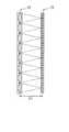
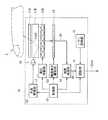
図1は、本発明の一実施の形態に係る生体認証装置(生体認証装置1)の断面構成を表したものである。この生体認証装置1は、認証対象である生体(例えば、図2に示した生体(指先)2)を撮像して生体認証を行い(例えば図2の場合、生体2の内部の静脈20を撮像して静脈認証を行い)、認証結果(後述する認証結果データDout)を出力するものであり、光源10と、カバーガラス11Aと、導光部11Bと、マイクロレンズアレイ12と、撮像素子13と、画像処理部14と、パターン保持部15と、認証部16と、光源駆動部181と、撮像素子駆動部182と、制御部19とから構成されている。 FIG. 1 shows a cross-sectional configuration of a biometric authentication device (biometric authentication device 1) according to an embodiment of the present invention. The
光源10は、撮像対象物である生体2へ向けて光を照射するものであり、例えば、LED(Light Emitting Diode)などにより構成される。なお、この光源10は、近赤外の波長領域(700nm〜1200nm程度の波長領域)の光を発するものであるのが好ましい。そのような波長領域の光を用いた場合、生体に対する透過率と、生体内の還元ヘモグロビン(静脈)への吸収率との兼ね合いより、生体2の静脈認証の際の光利用効率をより高めることができるからである。 The
導光部11Bは、図1に示したように、光源10からの射出光Loutを生体2の方向へと導く部分であり、例えばガラス基板や光ファイバなどにより構成される。カバーガラス11Aは、導光部11B上に配置され、生体認証装置1内部を保護する部分である。なお、このカバーガラス11Aは、認証の際に生体2が置かれる部分である。 As shown in FIG. 1, the
マイクロレンズアレイ12は、複数のマイクロレンズがマトリクス状に配列してなり、導光部11Bの下方(具体的には、導光部11Bと撮像素子13との間)に配置されている。このマイクロレンズアレイ12内のマイクロレンズは、撮像対象物である生体2の撮像レンズとして機能している。 The
撮像素子13は、マイクロレンズアレイ12からの光を受光して撮像データD1を取得するものであり、例えば図3に示したように、マイクロレンズアレイ12の焦点面(像側焦点距離:F1)に配置されている。なお、この撮像素子13は、例えば、マトリクス状に配列された複数のCCDなどにより構成される。 The
画像処理部14は、撮像素子13により得られた撮像データD1に対して後述する画像処理を施すことにより、画像処理データ(撮像データD2)を生成し、認証部16へ出力するものである。具体的には、詳細は後述するが、撮像データD1に対し、マイクロレンズの撮像領域ごとにその中心領域の切り出し処理および画像反転処理を施したのち、それぞれの画像の画像合成処理を施すことにより、撮像データD2を生成するものである。なお、この画像処理部14、ならびに後述する認証部16および制御部19は、例えばマイクロコンピュータなどにより構成される。 The
パターン保持部15は、生体認証の際に用いる生体認証パターン(認証の際に撮像して得られた撮像パターンに対する比較パターンであり、予め生体を撮像して得られたもの)が保持される部分であり、不揮発性の記録素子(例えば、EEPROM(Electrically Erasable Programmable Read Only Memory)など)により構成される。認証部16は、制御部19からの制御に応じて、画像処理部14から出力される撮像パターン(撮像データD2の撮像パターン)と、パターン保持部15に保持されている生体認証パターンとを比較することにより、撮像対象である生体2の認証を行う部分である。 The
光源駆動部181は、制御部19からの制御に応じて、光源10の発光駆動を行うものである。撮像素子駆動部182は、制御部19からの制御に応じて、撮像素子13の撮像駆動(受光駆動)を行うものである。 The light
制御部19は、画像処理部14、認証部16、光源駆動部181および撮像素子駆動部182の動作を制御するものである。具体的には、画像処理部14、認証部16、光源駆動部181および撮像素子駆動部182の動作を適宜制御するようになっている。 The
次に、図1〜図8を参照して、本実施の形態の生体認証装置1の動作(生体認証処理)について詳細に説明する。図4は、指の静脈パターン取得の際の光路を断面図で表したものである。 Next, the operation (biometric authentication process) of the
この生体認証装置1では、例えば図4に示したように、まず、カバーガラス11A上に生体(例えば、指先)2が置かれると、光源駆動部181の駆動動作により光源10から光Loutが射出され、導光部11Bおよびカバーガラス11Aを介して生体2へ照射される。この状態で生体2の撮像がなされると、マイクロレンズアレイ12への入射光線は、図中の光線L11のように屈折され、撮像素子13上で集光される。つまりこの場合、マイクロレンズアレイ12の焦点は、生体2の内部(静脈部分)および撮像素子13上に合わせられているため、生体2の静脈の撮像データD1(静脈パターン)が得られる。このようにして撮像素子13により得られた撮像データD1は、画像処理部14において以下説明する画像処理がなされ、撮像データD2(画像処理データ)として認証部16へ供給される。認証部16では、入力された撮像データD2(静脈パターン)と、パターン保持部15に保持されている静脈認証用の認証パターンとが比較され、これにより静脈認証がなされる。そして認証部16では、最終的な生体認証の結果(認証結果データDout)が出力され、これにより生体認証処理が終了となる。 In the
ここで、このように撮像対象物である生体2を近接して撮像する場合、例えば図5に示したように(ここでは、生体2が、マイクロレンズアレイ12の物体側焦点距離F2の位置にある場合)、各マイクロレンズの視野角特性等に起因して隣接するマイクロレンズの撮像領域(後述する撮像領域3)同士で重なりが生じるため、その重なりの領域(後述するオーバーラップ領域32)での映像(図中のオーバーラップ成分G11,G12,G21,G22)がノイズとなってしまう。なお、図中のオーバーラップ成分G11,G12は、撮像対象物である生体2における符号G1部分の撮像により生じたものであり、オーバーラップ成分G21,G22は、生体2における符号G2部分の撮像により生じたものである。このようなノイズ(オーバーラップ成分G11,G12,G21,G22)を含む撮像データD1をそのまま用いて生体認証を行った場合、撮像データの画質が劣化しているために認証精度が低下し、誤認証のおそれが生じてしまう。 Here, when the living
そこで本実施の形態の生体認証装置1では、画像処理部14において、撮像素子13により得られた撮像データD1に対して例えば図6〜図8に示すような画像処理動作がなされることにより、生体2を近接して撮像した場合の撮像データの画質劣化が低減されるようになっている。ここで、図6は、画像処理部14による画像処理動作の一例を流れ図で表したものであり、図7および図8(A)〜(D)は、このような画像処理動作を概念図および模式図で表したものである。なお、図7において、撮像データD1,D11,D12,D2における矢印は、マイクロレンズアレイ12内にある1つのマイクロレンズのみが解像している範囲を表しており、図8(A)〜(D)において、数字「1〜16」はそれぞれ、以下説明する中心領域3A〜3D内における撮像素子13の各画素の撮像データの中身を便宜的に示したものである。 Therefore, in the
この画像処理部14では、撮像素子13から、例えば図7および図8(A)に示したように、各マイクロレンズによる撮像領域3A〜3Dのうちのオーバーラップ領域32A〜32D(中心領域31A〜31Dの周辺の領域)内にオーバーラップ成分G11,G12,G21,G22が含まれる撮像データD1を取得すると(図6のステップS101)、まず、例えば図7および図8(B)に示したように、マイクロレンズの撮像領域3A〜3Dごとに、その中心領域31A〜31Dの切り出し処理がなされ、オーバーラップ領域32A〜32Dが切り離される(ステップS102)。これにより、オーバーラップ領域32A〜32D内に含まれるオーバーラップ成分G11,G12,G21,G22も、中心領域31A〜31D内の撮像データ(撮像データD11)から切り離される。なお、このような切り出し処理の際の中心領域31は、例えば図5に示したように、生体2がマイクロレンズアレイ12の物体側焦点距離F2の位置にある場合には、マイクロレンズ間のピッチ長と、マイクロレンズによる縮小倍率(例えば、図8の例では0.5倍)との乗算値により規定される。 In this
次に、画像処理部14では、例えば図7および図8(C)に示したように、マイクロレンズの撮像領域3A〜3Dごとに、中心領域31A〜31D内の撮像データ(撮像データD11)に対する画像反転処理がなされる(ステップS103)。具体的には、図8(B),(C)に示したように、中心領域31A〜31D内において、撮像データの並びが左右上下に反転する(この場合、対角線上の一対の撮像データの並びが逆になる)ことにより、中心領域33A〜33D内の撮像データからなる撮像データD12が生成される。 Next, in the
次に、画像処理部14では、例えば図7および図8(D)に示したように、撮像データD12における撮像領域3A〜3Dごとの画像(中心領域33A〜33D内の各撮像データ)に対する画像合成処理がなされ、これにより撮像データD2(画像処理データ)が生成される(ステップS104)。 Next, in the
最後に、このようにして画像処理部14において生成された画像処理後の撮像データD2が認証部16へ出力され(ステップS105)、画像処理動作が終了となる。 Finally, image data D2 after image processing generated in the
このようにして本実施の形態の生体認証装置1では、画像処理部14において、撮像素子13により得られた撮像データD1に対し、マイクロレンズの撮像領域3ごとにその中心領域31の切り出し処理および画像反転処理が施され、そののちにそれぞれの画像の画像合成処理が施されることにより、画像処理データ(撮像データD2)が生成される。ここで、この撮像データD2では、マイクロレンズの撮像領域3ごとにその中心領域31の切り出し処理が施されているため、撮像対象物である生体2が近接している場合であっても、隣接するマイクロレンズによる撮像領域3同士のオーバーラップ領域32が除去される。よって、近接撮像時における撮像画像(撮像データD2)の画質を向上させることが可能となる。 As described above, in the
また、撮像対象物である生体2へ向けて光Loutを照射する光源10と、画像処理部14により生成された画像処理データ(撮像データD2)に基づき生体2の認証を行う認証部16とを設け、生体認証装置1として構成されるようにしたので、オーバーラップ領域32の除去後の撮像データ(撮像データD2)に基づいて生体2の認証を行うことができる。よって、高画質の撮像画像(撮像データD2)による生体認証が可能となり、従来と比べて生体認証の認証精度を向上させることが可能となる。 Further, a
また、画像処理部14において、マイクロレンズの撮像領域3ごとに、撮像データD1に対して切り出し処理(ステップS102)を施したのちに画像反転処理(ステップS103)を施すようにしたので、後述するように、逆に画像反転処理を行ったのちに切り出し処理を行う場合と比べ、画像処理部14における処理負担を軽減することが可能となる。 In addition, since the
さらに、このようにして近接撮像時における撮像画像の向上が可能となるため、撮像光学系(マイクロレンズアレイ12や撮像素子13)を従来よりも薄型化することができ、生体認証装置1全体としても従来よりも薄型化することが可能となる。 Furthermore, since it is possible to improve the captured image at the time of close-up imaging in this way, the imaging optical system (the
(変形例)
次に、本発明の変形例について説明する。本変形例の生体認証装置は、上記実施の形態の生体認証装置1において、画像処理部14が、切り出し処理の際の中心領域の範囲が適切か否かを判断すると共に、その判断結果に応じて中心領域の範囲を変更することにより、撮像対象物(生体)2に対する倍率補正を行うようにしたものである。なお、上記実施の形態の構成要素と同一のものには同一の符号を付し、適宜説明を省略する。(Modification)
Next, a modified example of the present invention will be described. In the biometric authentication device of the present modification, in the
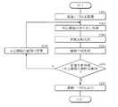
図9は、本変形例に係る画像処理部14による画像処理動作を流れ図で表したものであり、上記実施の形態における図6に対応するものである。 FIG. 9 is a flowchart showing an image processing operation performed by the
本変形例の画像処理動作では、まず、上記実施の形態のステップS101〜S104と同様にして、撮像データD1が取得されると共に、中心領域の切り出し処理、画像反転処理および画像合成処理が、この順に行われる(図9のステップS201〜S204)。ただし、本変形例では、中心領域の切り出し処理(ステップS202)の際の中心領域31,33の範囲は、特に予め指定されていなくてもよい。なお、上記実施の形態で説明したように、中心領域31,33の範囲を、マイクロレンズ間のピッチ長とマイクロレンズによる縮小倍率との乗算値により規定しておいてもよい。 In the image processing operation of the present modification, first, the imaging data D1 is acquired and the center region segmentation process, the image inversion process, and the image composition process are performed in the same manner as in steps S101 to S104 of the above embodiment. These are performed in order (steps S201 to S204 in FIG. 9). However, in this modification, the ranges of the center areas 31 and 33 in the center area cut-out process (step S202) may not be specified in advance. As described in the above embodiment, the range of the central regions 31 and 33 may be defined by a multiplication value of the pitch length between the microlenses and the reduction magnification by the microlens.
次に、本変形例では、画像処理部14によって、切り出し処理(ステップS202)の際の中心領域31,33の範囲が、適切か否か判断される(画像判断処理;ステップS205)。具体的には、詳細は後述するが、画像合成処理(ステップS204)後の画像(撮像データD2)における解像度が最も高くなる場合に、中心領域31,33の範囲が適切であると判断されるようになっている。そして、中心領域31,33の範囲が適切であると判断された場合には(ステップS205:Y)、撮像データD2がそのまま出力される(ステップS207)。一方、中心領域31,33の範囲が適切はないと判断された場合には(ステップS205:N)、判断結果に応じて中心領域31,33の範囲の変更処理が行われることにより、撮像対象物2に対する倍率補正がなされる(ステップS206)。そして、その後は、中心領域31,33の範囲が適切であると判断されるまで、ステップS202〜S204の処理が繰り返されることになる。 Next, in this modification, the
このようにして、中心領域31,33の範囲の変更処理を行うのは、以下の理由によるものである。すなわち、上記実施の形態では、中心領域31,33の範囲は、マイクロレンズ間のピッチ長とマイクロレンズによる縮小倍率との乗算値により予め規定されている(固定値となっている)。これにより、撮像対象物2が近接している場合であっても、隣接するマイクロレンズによる撮像領域のオーバーラップ領域32が除去され、近接撮像時における撮像画像(撮像データD2)の画質が向上するようになっている。ところが、1つのマイクロレンズのみが解像している範囲は、撮像する物体(撮像対象物2)の高さ、つまりマイクロレンズアレイ12の物体側焦点距離F2に依存することから、上記実施の形態とは異なり、撮像対象物2がこのマイクロレンズアレイ12の物体側焦点距離F2の位置にないときには(例えば、図10中の撮像対象物2A,2B参照)、中心領域31,33の範囲をどのように規定するのかが問題となる場合がある。そのような場合、中心領域31,33の範囲を、マイクロレンズ間のピッチ長とマイクロレンズによる縮小倍率との乗算値により規定しても、隣接するマイクロレンズによる撮像領域のオーバーラップ領域32の影響が完全には除去できない場合が生じるからである。 The reason for changing the range of the center areas 31 and 33 in this way is as follows. That is, in the above-described embodiment, the range of the center regions 31 and 33 is defined in advance by a multiplication value of the pitch length between the microlenses and the reduction magnification by the microlens (a fixed value). Thereby, even when the
そこで、本変形例では、中心領域31,33の範囲が適切か否か判断を判断する(ステップS205)と共に、その判断結果に応じて、例えば図11に示したように、中心領域31,33の範囲の変更処理を行い、撮像対象物2に対する倍率補正を行うようになっている。具体的には、画像処理部14は、撮像対象物2とマイクロレンズアレイ12との距離に応じて、中心領域31,33の範囲を変更するようになっている。より具体的には、撮像対象物2がマイクロレンズアレイ12の物体側焦点位置F2よりも遠くにある場合には(例えば、図10中の撮像対象物2A)、中心領域31,33の範囲が、マイクロレンズ間のピッチ長とマイクロレンズによる縮小倍率との乗算値により規定される規定範囲(図11中の中心領域31S,33Sの範囲)よりも、大きくなるように変更する(図11中の中心領域31P,33Pの範囲)。一方、撮像対象物2が物体側焦点位置F2よりも近くにある場合には(例えば、図10中の撮像対象物2B)、中心領域31,33の範囲が、マイクロレンズ間のピッチ長とマイクロレンズによる縮小倍率との乗算値により規定される規定範囲よりも小さくなるように変更する(図11中の中心領域31M,33Mの範囲)。これにより、撮像対象物2がこのマイクロレンズアレイ12の物体側焦点距離F2の位置にない場合であっても、切り出し処理の際の中心領域31,33の範囲が適切に設定されることになる。 Therefore, in this modification, it is determined whether or not the ranges of the center areas 31 and 33 are appropriate (step S205), and the center areas 31 and 33 are displayed according to the determination result, for example, as shown in FIG. The range correction process is performed, and the magnification correction for the
ここで、図12は、撮像対象物2であるチャートの一部が、マイクロレンズアレイ12の物体側焦点距離F2の位置ある場合の撮像データD2の一例を表している。また、図13は、撮像対象物2であるチャートの一部が、マイクロレンズアレイ12の物体側焦点距離F2から少し離れた位置ある場合(例えば、図10中の撮像対象物2A)の撮像データD2の一例を表している。なお、これら図12および図13において、(B)は、中心領域31,33の範囲が、マイクロレンズ間のピッチ長とマイクロレンズによる縮小倍率との乗算値により規定される規定範囲(図11中の中心領域31S,33Sの範囲に対応)である場合の撮像データD2を表している。また、(A)は、中心領域31,33の範囲が、この規定範囲に対して上下左右方向とも1画素分狭くなった範囲(図11中の中心領域31M,33Mの範囲に対応)である場合の撮像データD2を表している。また、(C)は、中心領域31,33の範囲が、上記規定範囲に対して上下左右方向とも1画素分広くなった範囲(図11中の中心領域31P,33Pの範囲に対応)である場合の撮像データD2を表している。ここで、図12(A)〜図12(C)に示した3種類の撮像データD2のうちでは、上記実施の形態で説明したように、中心領域31,33の範囲が、マイクロレンズ間のピッチ長とマイクロレンズによる縮小倍率との乗算値により規定される規定範囲である場合(図12(B))が、解像度が最も高くなっている。一方、図13(A)〜図13(C)に示した3種類の撮像データD2のうちでは、本変形例で説明したように、中心領域31,33の範囲が、上記規定範囲に対して上下左右方向とも1画素分広くなった範囲である場合(図13(C))が、解像度が最も高くなっている。これらの結果により、撮像対象物2とマイクロレンズアレイ12との距離に応じて中心領域31,33の範囲を変更することにより、撮像対象物2とマイクロレンズアレイ12との距離に関わらず、隣接するマイクロレンズによる撮像領域のオーバーラップ領域32が除去され、近接撮像時における撮像画像(撮像データD2)の画質が向上することが分かる。 Here, FIG. 12 shows an example of the imaging data D2 when a part of the chart that is the
以上のように本変形例では、画像処理部14において、中心領域31,33の範囲が適切か否か判断を判断すると共に、その判断結果に応じて、中心領域31,33の範囲の変更処理を行い、撮像対象物2に対する倍率補正を行うようにしたので、像対象物2がこのマイクロレンズアレイ12の物体側焦点距離F2の位置にない場合であっても、近接撮像時における撮像画像(撮像データD2)の画質を向上させることが可能となる。 As described above, in the present modification, the
また、倍率補正を行うことにより、距離センシングとして用いることも可能となる。 Moreover, it can also be used as distance sensing by performing magnification correction.
なお、本変形例では、中心領域31,33の範囲が適正化された画像を取得するために、画像判断処理において1枚の画像を選択する場合について説明したが、どのように判断するか、また、何枚の画像を出力するかは、そのような場合には限られない。例えば、撮像対象物2が2次元コードである場合には、適正に読み込まれた画像が、中心領域31,33の範囲が適正化された画像に対応するため、本変形例で説明したような画像判断処理は不要となる。 In the present modification, the case where one image is selected in the image determination process in order to acquire an image in which the ranges of the center areas 31 and 33 are optimized has been described. Further, how many images are output is not limited to such a case. For example, when the
また、本変形例では、撮像対象物2が、2次元形状であるチャートである場合について説明したが、撮像対象物2が3次元形状を持つ場合、取得画像(撮像データD1)内の位置に応じて、マイクロレンズからの距離が異なる場合が生じる。そのような場合には、マイクロレンズの撮像領域ごとに、撮像対象物2とマイクロレンズアレイ12との距離に応じて中心領域31,33の範囲を設定し、個別に本変形例の倍率補正を行うようにすればよい。 Further, in this modification, the case where the
以上、実施の形態および変形例を挙げて本発明を説明したが、本発明はこれらの実施の形態等に限定されるものではなく、種々の変形が可能である。 Although the present invention has been described with reference to the embodiment and the modification examples, the present invention is not limited to the embodiment and the like, and various modifications can be made.
例えば、上記実施の形態等では、画像処理部14において、切り出し処理(ステップS102)を行ったのちに画像反転処理(ステップS103)を行う場合について説明したが、逆に、画像反転処理を行ったのちに切り出し処理を行うようにしてもよい。 For example, in the above-described embodiment and the like, the case where the image inversion processing (step S103) is performed after the clipping processing (step S102) in the
また、上記実施の形態等では、図2や図4に示したように、生体2の静脈を撮像して静脈認証を行う生体認証装置1について説明したが、例えば図14に示したように、光線L12により生体2の指紋を撮像することにより、指紋認証を行うようにしてもよい。 In the above-described embodiment and the like, the
また、上記実施の形態等では、マイクロレンズアレイ12の焦点距離(像側焦点距離F1および物体側焦点距離F2)が固定の場合(マイクロレンズアレイ12の屈折力が固定の場合)について説明したが、例えば図15に示した生体認証装置1Aのように、マイクロレンズアレイに電圧を供給する電圧供給部17をさらに設けると共に、マイクロレンズ(マイクロレンズアレイ12A)が、この電圧供給部17から供給される電圧に応じてその屈折力が変化するようにしてもよい。具体的には、このマイクロレンズアレイ12Aでは、例えば図16に示したように、対向する一対の基板121,125間に液晶層123が形成され、この液晶層123と基板121,125との間には、それぞれ、電極122,124が形成されている。基板121,125は、それぞれ、例えばガラス基板などの透明基板により構成され、入射光線を透過可能となっている。電極122,124には、電圧供給部17から電圧が供給される。これら電極122,124は、それぞれ、例えばITO(Indium Tin Oxide;酸化インジウムスズ)などの透明電極により構成され、基板121,125と同様に、入射光線を透過可能となっている。電極122,124の表面S1,S2のうち、電極122側の表面S1には、凹状の複数の曲面がマトリクス状に形成され、これにより複数の液晶マイクロレンズを構成するようになっている。液晶層123は、例えばネマティック液晶などの液晶材料により構成され、電極122,124間に印加される電圧に応じて屈折率が変化するようになっている。このような構成のマイクロレンズアレイ12Aでは、マイクロレンズ12Aへの供給電圧が低いと、それに応じて液晶層123の屈折率も小さくなり、その結果、マイクロレンズ12への入射光線は、例えば図17中の光線L1のように、比較的小さな屈折角となるような屈折方向へ屈折され、比較的長い焦点距離(例えば、図17に示した光軸L0上の焦点位置P1)で集光される。逆に、マイクロレンズ12Aへの供給電圧が高いと、それに応じて液晶層123の屈折率も大きくなり、その結果、マイクロレンズ12への入射光線は、例えば図17中の光線L2のように、比較的大きな屈折角となるような屈折方向へ屈折され、比較的短い焦点距離(例えば、図17に示した光軸L0上の焦点位置P2)で集光される。このようにしてマイクロレンズ12Aへの供給電圧を変化させることによりマイクロレンズ12Aにおいて異なる屈折力が発現し、マイクロレンズアレイ12Aの焦点距離が変化する。よって、このようなマイクロレンズアレイ12Aを備えた生体認証装置1Aでは、図4に示したような静脈認証と図14に示したような指紋認証とを併用することが可能となる。 In the above-described embodiment and the like, the case where the focal lengths (image side focal length F1 and object side focal length F2) of the
なお、液晶層123を構成する液晶材料の種類によっては、逆に、生体2の静脈パターンを取得する際には、電圧供給部17からマイクロレンズアレイ12A内のマイクロレンズへ所定の閾値電圧よりも高い電圧を供給することで、液晶層123の屈折率を小さくし、マイクロレンズへの入射光線の屈折角を小さくする一方、生体2の指紋パターンを取得する際には、電圧供給部17からマイクロレンズアレイ12A内のマイクロレンズへ所定の閾値電圧よりも低い電圧を供給することで、液晶層123の屈折率を大きくし、マイクロレンズへの入射光線の屈折角を大きくするようにすることも可能である。また、図16および図17では、電極122,124の表面S1,S2のうちの表面S1が曲面である場合について説明したが、例えば、表面S2も曲面とし、液晶層123の両側が曲面となるようなマイクロレンズとしてもよい。また、図16および図17では、マイクロレンズが液晶マイクロレンズにより構成されている場合について説明したが、印加電圧に応じて入射光線の屈折方向を変位可能なものであれば、他の構成のマイクロレンズとしてもよく、例えば、2種類の異なる液体層を利用した液体マイクロレンズなどを用いてもよい。 Depending on the type of the liquid crystal material constituting the
さらに、上記実施の形態等では、本発明の撮像装置を用いたアプリケーションの一例として生体認証装置を挙げて説明したが、本発明の撮像装置は、例えば、2次元コードの撮像のような接写が必要な撮像などの他のアプリケーションにも適用することが可能である。 Furthermore, in the above-described embodiment and the like, the biometric authentication device has been described as an example of an application using the imaging device of the present invention. However, the imaging device of the present invention can perform close-ups such as imaging of a two-dimensional code, for example. It can also be applied to other applications such as necessary imaging.
Claims (11)
Translated fromJapanese前記マイクロレンズアレイ部で集光された光に基づき、撮像対象物の撮像データを取得する撮像素子と、
前記撮像素子により得られた撮像データに対して、前記マイクロレンズの撮像領域ごとにその中心領域の切り出し処理および画像反転処理を施したのち、それぞれの画像の画像合成処理を施すことにより、画像処理データを生成する画像処理部と
を備え、
前記撮像対象物が前記マイクロレンズアレイ部の物体側焦点位置にある場合、前記切り出し処理の際の前記中心領域は、前記マイクロレンズ間のピッチ長と、前記マイクロレンズによる縮小倍率との乗算値により規定される
撮像装置。A microlens array section having a plurality of microlenses;
Based on the light collected by the microlens array unit, an imaging device that acquires imaging data of the imaging object;
The image data obtained by the image sensoris subjected to image segmentation processing and image inversion processing for each imaging region of the microlens, and then image synthesis processing is performed foreach image. An image processing unit for generating data,
When the object to be imaged is at the object side focal position of the microlens array unit, the center region in the cutout process is obtained by multiplying the pitch length between the microlenses and the reduction magnification by the microlens. An imaging devicethat is defined .
請求項1に記載の撮像装置。The imaging apparatus according to claim 1, wherein the image processing unit performs the image inversion processing after performing the clipping processing on the imaging data for each imaging region of the microlens.
請求項1または請求項2に記載の撮像装置。The image processing unit determines whether or not the range of the center region at the time of the clipping process is appropriate, and changes the center region according to the determination result, thereby correcting the magnification of the imaging object. The imaging device according toclaim 1or 2 .
請求項3に記載の撮像装置。The imaging apparatus according to claim3 , wherein the image processing unit changes a range of the central region according to a distance between the imaging object and the microlens array unit.
前記撮像対象物が前記マイクロレンズアレイ部の物体側焦点位置よりも遠くにある場合には、前記中心領域の範囲が、前記マイクロレンズ間のピッチ長と前記マイクロレンズによる縮小倍率との乗算値により規定される規定範囲よりも大きくなるように変更すると共に、
前記撮像対象物が前記物体側焦点位置よりも近くにある場合には、前記中心領域の範囲が前記規定範囲よりも小さくなるように変更する
請求項4に記載の撮像装置。The image processing unit
When the imaging object is farther than the object side focal position of the microlens array unit, the range of the central region is determined by a product of a pitch length between the microlenses and a reduction magnification by the microlens. Change it to be larger than the prescribed range, and
The imaging apparatus according to claim4 , wherein when the imaging target is closer to the object-side focal position, the range of the central region is changed to be smaller than the specified range.
請求項3に記載の撮像装置。The imaging apparatus according to claim3 , wherein the image processing unit determines that the range of the central region is appropriate when the resolution in the image after the image synthesis processing is the highest.
請求項3に記載の撮像装置。Wherein the image processing unit, for each imaging region of the microlens, wherein to set the range of the central region in accordance with the distance between the imaging object and the microlens array section, according to claim3 for individually the magnification correction The imaging device described in 1.
前記マイクロレンズは、前記電圧供給部から供給される電圧に応じて、その屈折力が変化するように構成されている
請求項1ないし請求項7のいずれか1項に記載の撮像装置。A voltage supply unit for supplying a voltage to the microlens array unit;
The imaging device according toany one of claims 1 to 7 , wherein the microlens is configured to change its refractive power in accordance with a voltage supplied from the voltage supply unit.
一対の基板と、
前記基板上に形成され、前記電圧供給部からの電圧が印加される一対の電極と、
前記一対の電極間に設けられた液晶層と
を含んで構成され、
前記一対の電極のうちの少なくとも一方が、前記マイクロレンズを構成するための曲面を有している
請求項8に記載の撮像装置。The microlens array part is
A pair of substrates;
A pair of electrodes formed on the substrate and applied with a voltage from the voltage supply unit;
A liquid crystal layer provided between the pair of electrodes, and
The imaging device according to claim8 , wherein at least one of the pair of electrodes has a curved surface for constituting the microlens.
前記生体へ向けて光を照射する光源と、
前記画像処理部により生成された画像処理データに基づき、前記生体の認証を行う認証部と
を備えた請求項1ないし請求項9のいずれか1項に記載の撮像装置。The imaging object is a living body;
A light source that emits light toward the living body;
The image processing unit based on the image processing data generated by the imaging apparatus according toany one of claims 1to 9 comprising an authentication section performing authentication of the living body.
前記マイクロレンズアレイ部で集光された光に基づき、撮像対象物の撮像データを取得する撮像素子と、Based on the light collected by the microlens array unit, an imaging device that acquires imaging data of an imaging object;
前記撮像素子により得られた撮像データに対して、前記マイクロレンズの撮像領域ごとにその中心領域の切り出し処理および画像反転処理を施したのち、それぞれの画像の画像合成処理を施すことにより、画像処理データを生成する画像処理部とThe image data obtained by the image sensor is subjected to image segmentation processing and image inversion processing for each imaging region of the microlens, and then image synthesis processing is performed for each image. An image processing unit for generating data;
を備え、With
前記画像処理部は、The image processing unit
前記切り出し処理の際の前記中心領域の範囲が適切か否かを判断し、その判断結果に応じて前記中心領域の範囲を変更することにより、前記撮像対象物に対する倍率補正を行うと共に、It is determined whether or not the range of the central region at the time of the clipping process is appropriate, and by changing the range of the central region according to the determination result, the magnification correction for the imaging object is performed,
前記中心領域の範囲を変更する際に、When changing the range of the central region,
前記撮像対象物が前記マイクロレンズアレイ部の物体側焦点位置よりも遠くにある場合には、前記中心領域の範囲が、前記マイクロレンズ間のピッチ長と前記マイクロレンズによる縮小倍率との乗算値により規定される規定範囲よりも大きくなるように変更すると共に、When the imaging object is farther than the object side focal position of the microlens array unit, the range of the central region is determined by a product of a pitch length between the microlenses and a reduction magnification by the microlens. Change it to be larger than the prescribed range, and
前記撮像対象物が前記物体側焦点位置よりも近くにある場合には、前記中心領域の範囲が前記規定範囲よりも小さくなるように変更するWhen the imaging target is closer to the object-side focal position, the center area is changed so as to be smaller than the specified range.
撮像装置。Imaging device.
Priority Applications (1)
| Application Number | Priority Date | Filing Date | Title |
|---|---|---|---|
| JP2009525429AJP5397222B2 (en) | 2007-07-30 | 2008-07-30 | Imaging device |
Applications Claiming Priority (4)
| Application Number | Priority Date | Filing Date | Title |
|---|---|---|---|
| JP2007197606 | 2007-07-30 | ||
| JP2007197606 | 2007-07-30 | ||
| PCT/JP2008/063649WO2009017149A1 (en) | 2007-07-30 | 2008-07-30 | Imaging device |
| JP2009525429AJP5397222B2 (en) | 2007-07-30 | 2008-07-30 | Imaging device |
Publications (2)
| Publication Number | Publication Date |
|---|---|
| JPWO2009017149A1 JPWO2009017149A1 (en) | 2010-10-21 |
| JP5397222B2true JP5397222B2 (en) | 2014-01-22 |
Family
ID=40304379
Family Applications (1)
| Application Number | Title | Priority Date | Filing Date |
|---|---|---|---|
| JP2009525429AExpired - Fee RelatedJP5397222B2 (en) | 2007-07-30 | 2008-07-30 | Imaging device |
Country Status (5)
| Country | Link |
|---|---|
| US (1) | US8463001B2 (en) |
| JP (1) | JP5397222B2 (en) |
| KR (1) | KR20100038362A (en) |
| CN (1) | CN101755284B (en) |
| WO (1) | WO2009017149A1 (en) |
Families Citing this family (15)
| Publication number | Priority date | Publication date | Assignee | Title |
|---|---|---|---|---|
| JP5292821B2 (en)* | 2008-01-16 | 2013-09-18 | ソニー株式会社 | Vein image acquisition device and vein image acquisition method |
| EP2364484A4 (en)* | 2008-11-03 | 2012-05-09 | Cross Match Technologies Inc | Apparatus and method for the identification of fake fingerprints |
| JP5326793B2 (en)* | 2009-05-14 | 2013-10-30 | ソニー株式会社 | Vein imaging device, vein image interpolation method and program |
| JP5326792B2 (en)* | 2009-05-14 | 2013-10-30 | ソニー株式会社 | Vein imaging device, positional deviation interpolation method and program |
| CN102867168A (en)* | 2011-07-04 | 2013-01-09 | 光宝新加坡有限公司 | Image extraction system and image processing method thereof |
| CN104055489B (en)* | 2014-07-01 | 2016-05-04 | 李栋 | A kind of blood vessel imaging device |
| US11010588B2 (en)* | 2015-06-18 | 2021-05-18 | Shenzhen GOODIX Technology Co., Ltd. | Large-sensing-area under-display optical sensor |
| CN108140125B (en)* | 2015-09-15 | 2021-11-02 | 上海箩箕技术有限公司 | Optical Fingerprint Imaging Systems and Area Array Sensors |
| JP2017098631A (en)* | 2015-11-18 | 2017-06-01 | オリンパス株式会社 | Image combination processing device |
| CN106873284B (en)* | 2017-04-10 | 2019-10-29 | 京东方科技集团股份有限公司 | A kind of display device and its control method |
| CN109145849A (en)* | 2018-08-30 | 2019-01-04 | 维沃移动通信有限公司 | Fingerprint imaging method and device for terminal equipment |
| CN112639705B (en) | 2018-09-05 | 2023-08-01 | 指纹卡安娜卡敦知识产权有限公司 | Optical fingerprint sensor module and method of operating an optical fingerprint sensor module |
| US11301664B2 (en) | 2018-09-12 | 2022-04-12 | Fingerprint Cards Anacatum Ip Ab | Reconstruction of fingerprint subimages |
| US11508181B2 (en) | 2019-02-18 | 2022-11-22 | Fingerprint Cards Anacatum Ip Ab | Optical biometric imaging device and method of operating an optical biometric imaging device |
| CN111629135A (en)* | 2020-05-27 | 2020-09-04 | 维沃移动通信有限公司 | Camera modules and electronic equipment |
Citations (3)
| Publication number | Priority date | Publication date | Assignee | Title |
|---|---|---|---|---|
| JPH10210272A (en)* | 1997-01-23 | 1998-08-07 | Fuji Xerox Co Ltd | Image reader |
| JP2003084259A (en)* | 2001-09-10 | 2003-03-19 | Citizen Electronics Co Ltd | Compound liquid crystal micro lens for contact image sensor |
| WO2006077718A1 (en)* | 2005-01-20 | 2006-07-27 | Matsushita Electric Industrial Co., Ltd. | Lens array and image sensor provided with lens array |
Family Cites Families (6)
| Publication number | Priority date | Publication date | Assignee | Title |
|---|---|---|---|---|
| JPH0721373A (en) | 1993-06-17 | 1995-01-24 | Asahi Optical Co Ltd | Personal identification device |
| US6628390B1 (en)* | 2000-01-24 | 2003-09-30 | Kenneth C. Johnson | Wafer alignment sensor using a phase-shifted microlens array |
| US6643067B2 (en)* | 2000-11-22 | 2003-11-04 | Seiko Epson Corporation | Electro-optical device and electronic apparatus |
| CA2496839A1 (en) | 2004-07-19 | 2006-01-19 | Woodland Chemical Systems Inc. | Process for producing ethanol from synthesis gas rich in carbon monoxide |
| JP2006285487A (en) | 2005-03-31 | 2006-10-19 | Canon Inc | Biometric information detection apparatus and biometric authentication apparatus |
| JP4024264B2 (en) | 2005-10-28 | 2007-12-19 | 京セラ株式会社 | Biometric authentication device |
- 2008
- 2008-07-30JPJP2009525429Apatent/JP5397222B2/ennot_activeExpired - Fee Related
- 2008-07-30KRKR1020107000510Apatent/KR20100038362A/ennot_activeWithdrawn
- 2008-07-30CNCN200880100117XApatent/CN101755284B/ennot_activeExpired - Fee Related
- 2008-07-30WOPCT/JP2008/063649patent/WO2009017149A1/enactiveApplication Filing
- 2008-07-30USUS12/452,324patent/US8463001B2/ennot_activeExpired - Fee Related
Patent Citations (3)
| Publication number | Priority date | Publication date | Assignee | Title |
|---|---|---|---|---|
| JPH10210272A (en)* | 1997-01-23 | 1998-08-07 | Fuji Xerox Co Ltd | Image reader |
| JP2003084259A (en)* | 2001-09-10 | 2003-03-19 | Citizen Electronics Co Ltd | Compound liquid crystal micro lens for contact image sensor |
| WO2006077718A1 (en)* | 2005-01-20 | 2006-07-27 | Matsushita Electric Industrial Co., Ltd. | Lens array and image sensor provided with lens array |
Also Published As
| Publication number | Publication date |
|---|---|
| KR20100038362A (en) | 2010-04-14 |
| US20100142770A1 (en) | 2010-06-10 |
| JPWO2009017149A1 (en) | 2010-10-21 |
| CN101755284A (en) | 2010-06-23 |
| US8463001B2 (en) | 2013-06-11 |
| WO2009017149A1 (en) | 2009-02-05 |
| CN101755284B (en) | 2012-08-29 |
Similar Documents
| Publication | Publication Date | Title |
|---|---|---|
| JP5397222B2 (en) | Imaging device | |
| JP4306744B2 (en) | Biometric authentication device | |
| JP4636340B2 (en) | Biological imaging device | |
| JP4379500B2 (en) | Biological imaging device | |
| JP4640415B2 (en) | Biometric authentication device | |
| JP4389957B2 (en) | Biometric authentication device | |
| US9113066B2 (en) | Imaging device and method with transporting microlens array | |
| CN101414354B (en) | Image input device and personal authentication device | |
| JPWO2008123584A1 (en) | Biometric authentication device | |
| US8180119B2 (en) | Imaging apparatus and imaging method | |
| US20090232362A1 (en) | Biometric information acquisition apparatus and biometric authentication apparatus | |
| JP2008212311A (en) | Biometric authentication device | |
| JP2008256454A (en) | Optical characteristic measuring device and method | |
| JP2007299084A (en) | Image reading apparatus | |
| JP2016133905A (en) | Luminaire and living matter authentication device | |
| CN101640706A (en) | Image pickup device having display function and mobile communication terminal | |
| JP4935637B2 (en) | Biological imaging apparatus and biological imaging method | |
| CN111557050A (en) | Biological information acquisition device, biological information acquisition method, and wearable device | |
| JP2008113704A (en) | Biometric authentication device | |
| JP4953292B2 (en) | Image input device, personal authentication device, and electronic device | |
| JP2010015365A (en) | Biometrics device and biometrics method | |
| JP2008109952A (en) | Biometric authentication device | |
| KR102125082B1 (en) | Image processing apparatus and control method thereof | |
| JP2010009157A (en) | Finger vein authentication device and information processor | |
| JP2008113703A (en) | Biometric authentication device |
Legal Events
| Date | Code | Title | Description |
|---|---|---|---|
| A621 | Written request for application examination | Free format text:JAPANESE INTERMEDIATE CODE: A621 Effective date:20110629 | |
| A131 | Notification of reasons for refusal | Free format text:JAPANESE INTERMEDIATE CODE: A131 Effective date:20130212 | |
| A521 | Request for written amendment filed | Free format text:JAPANESE INTERMEDIATE CODE: A523 Effective date:20130311 | |
| TRDD | Decision of grant or rejection written | ||
| A01 | Written decision to grant a patent or to grant a registration (utility model) | Free format text:JAPANESE INTERMEDIATE CODE: A01 Effective date:20130924 | |
| A61 | First payment of annual fees (during grant procedure) | Free format text:JAPANESE INTERMEDIATE CODE: A61 Effective date:20131007 | |
| LAPS | Cancellation because of no payment of annual fees |