JP5396432B2 - Program, information storage medium, information processing system, and information processing method - Google Patents
Program, information storage medium, information processing system, and information processing methodDownload PDFInfo
- Publication number
- JP5396432B2 JP5396432B2JP2011118457AJP2011118457AJP5396432B2JP 5396432 B2JP5396432 B2JP 5396432B2JP 2011118457 AJP2011118457 AJP 2011118457AJP 2011118457 AJP2011118457 AJP 2011118457AJP 5396432 B2JP5396432 B2JP 5396432B2
- Authority
- JP
- Japan
- Prior art keywords
- moved
- candidate
- virtual space
- information processing
- value
- Prior art date
- Legal status (The legal status is an assumption and is not a legal conclusion. Google has not performed a legal analysis and makes no representation as to the accuracy of the status listed.)
- Active
Links
- 230000010365information processingEffects0.000titleclaimsdescription27
- 238000003672processing methodMethods0.000titleclaimsdescription6
- 230000033001locomotionEffects0.000claimsdescription92
- 230000008859changeEffects0.000claimsdescription20
- 238000000034methodMethods0.000description59
- 230000008569processEffects0.000description58
- 210000000988bone and boneAnatomy0.000description55
- 238000007726management methodMethods0.000description52
- 238000004088simulationMethods0.000description29
- 230000007704transitionEffects0.000description21
- 238000013500data storageMethods0.000description20
- 230000006870functionEffects0.000description11
- 230000009466transformationEffects0.000description9
- 239000011159matrix materialSubstances0.000description7
- 230000005484gravityEffects0.000description6
- 238000006243chemical reactionMethods0.000description5
- 238000010586diagramMethods0.000description5
- 230000004913activationEffects0.000description4
- 238000004364calculation methodMethods0.000description4
- 238000013016dampingMethods0.000description4
- 230000003287optical effectEffects0.000description4
- 238000004891communicationMethods0.000description3
- 239000000203mixtureSubstances0.000description3
- 238000005293physical lawMethods0.000description2
- 210000000689upper legAnatomy0.000description2
- 241000406668Loxodonta cyclotisSpecies0.000description1
- 238000007664blowingMethods0.000description1
- 239000002775capsuleSubstances0.000description1
- 230000007423decreaseEffects0.000description1
- 238000007373indentationMethods0.000description1
- 238000007562laser obscuration time methodMethods0.000description1
- 239000004973liquid crystal related substanceSubstances0.000description1
- 230000009467reductionEffects0.000description1
Images


Landscapes
- Processing Or Creating Images (AREA)
Description
Translated fromJapanese本発明は、プログラム、情報記憶媒体、情報処理システム及び情報処理方法に関する。 The present invention relates to a program, an information storage medium, an information processing system, and an information processing method.
仮想空間内に配置されたオブジェクトを、仮想空間内に配置された視点位置及び視線方向から見た様子を表すフレーム画像を順次生成し、表示装置に表示させる情報処理システムがある。また、古典力学の法則等の物理法則をシミュレートするソフトウェアである物理エンジンを活用することで、仮想空間内に配置されたオブジェクトの動きのリアリティを高めた情報処理システムもある。 There is an information processing system that sequentially generates a frame image representing a state in which an object placed in a virtual space is viewed from a viewpoint position and a line-of-sight direction placed in the virtual space, and displays the frame image on a display device. In addition, there is an information processing system that uses a physics engine, which is software that simulates physical laws such as the laws of classical mechanics, to increase the reality of the movement of objects placed in a virtual space.
物理エンジンは、一般的に、ある時点における各オブジェクトに設定された物理量(例えば、位置、向き、質量、慣性モーメント、速度、角速度、など)を表すパラメータの値、仮想空間全体に関わる物理量(例えば、風速)を表すパラメータの値、などに基づいて、所定時間が経過した後における各オブジェクトの位置や向きを決定している。 In general, a physics engine is a parameter that represents a physical quantity (for example, position, orientation, mass, moment of inertia, velocity, angular velocity, etc.) set for each object at a certain point in time, a physical quantity related to the entire virtual space (eg, , The position and orientation of each object after a predetermined time has elapsed based on the value of the parameter representing the wind speed).
また、仮想空間内に配置されたオブジェクトを、ユーザによるコントローラ等の操作入力の入力量に応じて移動させることができる情報処理システムも知られている。 There is also known an information processing system that can move an object arranged in a virtual space according to an input amount of an operation input by a user such as a controller.
例えば、ユーザが移動させることができるオブジェクトの移動先の位置を、操作入力の入力量に基づいて決定した際に、仮想空間内に配置されているオブジェクト(例えば、壁を表すオブジェクト)にめりこんでしまうことがある。このことを防ぐために、操作入力の入力量に基づいて決定される位置に仮配置された移動対象のオブジェクトに対して、物理エンジンによるシミュレーション処理を実行して、その実行結果として特定される移動対象のオブジェクトの位置を、そのオブジェクトの移動先の位置として決定するようにすることが考えられる。例えば、移動対象のオブジェクトが仮配置される位置が壁を表すオブジェクトの中に入っていると、壁から押し戻された位置を移動対象のオブジェクトの移動先の位置として決定するようにすることが考えられる。 For example, when the destination position of an object that can be moved by the user is determined based on the input amount of the operation input, it is turned into an object (for example, an object representing a wall) arranged in the virtual space. There are times when it ends up. In order to prevent this, the object to be moved that is temporarily arranged at the position determined based on the input amount of the operation input is subjected to the simulation process by the physics engine, and the movement target identified as the execution result The position of the object may be determined as the position to which the object is moved. For example, if the position where the object to be moved is temporarily placed is in the object representing the wall, the position pushed back from the wall may be determined as the position to which the object to be moved is moved. It is done.
しかし、こうすると、ユーザが移動対象のオブジェクトを壁を表すオブジェクトの縁に沿って移動させようとした際に、移動対象のオブジェクトが壁の表面にひっかかりがちになり、オブジェクトが移動する様子の表現としては不自然なものとなってしまうおそれがある。 However, in this way, when the user tries to move the object to be moved along the edge of the object representing the wall, the object to be moved tends to get caught on the surface of the wall, and an expression of how the object moves. As a result, it may become unnatural.
また、例えば、移動対象のオブジェクトが仮配置される位置が、小さな段差の中に入っていると、物理エンジンにより、段差から想定以上に乖離した位置が移動対象のオブジェクトの移動先の位置として決定されてしまうことがある。こうなると、小さな段差を超える際に移動対象のオブジェクトが吹っ飛んでしまうというようなことが発生するおそれがあり、やはり、オブジェクトが移動する様子の表現としては不自然なものとなってしまうおそれがある。 Also, for example, if the position where the object to be moved is temporarily placed is in a small step, the position that deviates more than expected from the step is determined by the physical engine as the destination position of the object to be moved. It may be done. If this happens, there is a possibility that the object to be moved will blow away when a small step is exceeded, and it may be unnatural as an expression of how the object moves. .
本発明は上記課題に鑑みてなされたものであって、その目的の1つは、情報処理システムにおける仮想空間内に配置されているオブジェクトが移動する様子の表現が不自然になるおそれを低減することにある。 The present invention has been made in view of the above problems, and one of its purposes is to reduce the possibility of an unnatural expression of how an object arranged in a virtual space in an information processing system moves. There is.
上記課題を解決するために、本発明に係るプログラムは、仮想空間内に配置されているオブジェクトの移動を制御する情報処理システムとしてコンピュータを機能させるプログラムであって、移動対象のオブジェクトの現在位置に基づいて、前記移動対象のオブジェクトの移動先の基準となる基準位置、及び、前記移動対象のオブジェクトの移動先の候補となる複数の候補位置を決定する決定手段、前記複数の候補位置のうちの少なくとも一部を、当該候補位置と仮想空間内に配置されている他のオブジェクトの位置との関係に基づいて変更する候補位置変更手段、少なくとも一部について前記候補位置変更手段により位置が変更された前記複数の候補位置のうち前記基準位置から最も近い位置に、前記移動対象のオブジェクトの位置を変更する移動対象オブジェクト位置変更手段、として前記コンピュータを機能させることを特徴とする。 In order to solve the above problems, a program according to the present invention is a program that causes a computer to function as an information processing system that controls the movement of an object arranged in a virtual space, and that is provided at the current position of the object to be moved. A determination unit that determines a reference position that is a reference for a movement destination of the object to be moved, and a plurality of candidate positions that are candidates for a movement destination of the object to be moved, of the plurality of candidate positions, Candidate position changing means for changing at least a part based on the relationship between the candidate position and the position of another object arranged in the virtual space, and at least a part of the position is changed by the candidate position changing means The position of the object to be moved is changed to a position closest to the reference position among the plurality of candidate positions. Characterized thereby that the moving object position changing means functions the computer as a.
また、本発明に係る情報記憶媒体は、仮想空間内に配置されているオブジェクトの移動を制御する情報処理システムとしてコンピュータを機能させるプログラムを記憶したコンピュータ読み取り可能な情報記憶媒体であって、移動対象のオブジェクトの現在位置に基づいて、前記移動対象のオブジェクトの移動先の基準となる基準位置、及び、前記移動対象のオブジェクトの移動先の候補となる複数の候補位置を決定する決定手段、前記複数の候補位置のうちの少なくとも一部を、当該候補位置と仮想空間内に配置されている他のオブジェクトの位置との関係に基づいて変更する候補位置変更手段、少なくとも一部について前記候補位置変更手段により位置が変更された前記複数の候補位置のうち前記基準位置から最も近い位置に、前記移動対象のオブジェクトの位置を変更する移動対象オブジェクト位置変更手段、として前記コンピュータを機能させることを特徴とするプログラムを記憶したコンピュータ読み取り可能な情報記憶媒体である。 An information storage medium according to the present invention is a computer-readable information storage medium storing a program that causes a computer to function as an information processing system that controls movement of an object arranged in a virtual space, Determining means for determining, based on the current position of the object to be moved, a reference position serving as a reference for the movement destination of the object to be moved and a plurality of candidate positions to be candidates for the movement destination of the object to be moved; Candidate position changing means for changing at least a part of the candidate position based on the relationship between the candidate position and the position of another object arranged in the virtual space, and at least a part of the candidate position changing means The movement to the position closest to the reference position among the plurality of candidate positions whose positions have been changed by A computer readable information storage medium storing a program for causing the computer to function the position of the elephant object moving target object position changing means for changing, as a.
また、本発明に係る情報処理システムは、仮想空間内に配置されているオブジェクトの移動を制御する情報処理システムであって、移動対象のオブジェクトの現在位置に基づいて、前記移動対象のオブジェクトの移動先の基準となる基準位置、及び、前記移動対象のオブジェクトの移動先の候補となる複数の候補位置を決定する決定手段と、前記複数の候補位置のうちの少なくとも一部を、当該候補位置と仮想空間内に配置されている他のオブジェクトの位置との関係に基づいて変更する候補位置変更手段と、少なくとも一部について前記候補位置変更手段により位置が変更された前記複数の候補位置のうち前記基準位置から最も近い位置に、前記移動対象のオブジェクトの位置を変更する移動対象オブジェクト位置変更手段と、を含むことを特徴とする。 An information processing system according to the present invention is an information processing system for controlling movement of an object arranged in a virtual space, and the movement of the object to be moved is based on a current position of the object to be moved. Determining means for determining a reference position serving as a previous reference and a plurality of candidate positions that are candidates for the movement destination of the object to be moved; and at least some of the plurality of candidate positions as the candidate position Candidate position changing means for changing based on the relationship with the position of another object arranged in the virtual space, and among the plurality of candidate positions whose positions have been changed by the candidate position changing means for at least some of the positions Moving object position changing means for changing the position of the object to be moved at a position closest to a reference position. And features.
また、本発明に係る情報処理方法は、仮想空間内に配置されているオブジェクトの移動を制御する情報処理方法であって、移動対象のオブジェクトの現在位置に基づいて、前記移動対象のオブジェクトの移動先の基準となる基準位置、及び、前記移動対象のオブジェクトの移動先の候補となる複数の候補位置を決定する決定ステップと、前記複数の候補位置のうちの少なくとも一部を、当該候補位置と仮想空間内に配置されている他のオブジェクトの位置との関係に基づいて変更する候補位置変更ステップと、少なくとも一部について前記候補位置変更ステップにより位置が変更された前記複数の候補位置のうち前記基準位置から最も近い位置に、前記移動対象のオブジェクトの位置を変更する移動対象オブジェクト位置変更ステップと、を含むことを特徴とする。 An information processing method according to the present invention is an information processing method for controlling movement of an object arranged in a virtual space, and the movement of the object to be moved is based on a current position of the object to be moved. A determination step for determining a reference position serving as a previous reference, and a plurality of candidate positions serving as movement destination candidates for the object to be moved; and at least some of the plurality of candidate positions as the candidate position A candidate position changing step for changing based on the relationship with the position of another object arranged in the virtual space, and at least a part of the plurality of candidate positions whose positions have been changed by the candidate position changing step A moving object position changing step for changing the position of the moving object to a position closest to a reference position; And wherein the Mukoto.
本発明によれば、複数の候補位置のうち基準位置から最も近い位置に移動対象のオブジェクトの位置が変更されるので、情報処理システムにおける仮想空間内に配置されているオブジェクトが移動する様子の表現が不自然になるおそれを低減することができる。 According to the present invention, since the position of the object to be moved is changed to a position closest to the reference position among the plurality of candidate positions, the expression of the movement of the object arranged in the virtual space in the information processing system Can reduce the risk of unnaturalness.
本発明の一態様では、前記最も近い位置を基準として設定される複数の位置のそれぞれと、前記移動対象のオブジェクトが配置されている位置と、を結ぶ線分上に他のオブジェクトが存在するか否かを判定する判定手段、として前記コンピュータをさらに機能させ、前記オブジェクト位置変更手段は、少なくとも1つの前記線分について線分上に他のオブジェクトが存在しないと前記判定手段により判定される場合は、前記最も近い位置に前記移動対象のオブジェクトの位置を変更し、そうでない場合は、前記移動対象のオブジェクトの位置を変更しないことを特徴とする。 In one aspect of the present invention, is there another object on a line segment connecting each of the plurality of positions set with the closest position as a reference and the position where the object to be moved is arranged? The computer further functions as a determination unit for determining whether or not the object position changing unit determines that the determination unit determines that there is no other object on the line segment for at least one of the line segments. The position of the object to be moved is changed to the closest position, and if not, the position of the object to be moved is not changed.
また、本発明の一態様では、移動対象オブジェクト位置変更手段により前記移動対象のオブジェクトの位置が変更された後に、前記移動対象のオブジェクトに設定される速度ベクトルに基づいて算出される位置に前記移動対象のオブジェクトをさらに移動させる移動手段、として前記コンピュータをさらに機能させ、前記移動手段は、所定の条件を満足する場合に、前記移動対象のオブジェクトに設定される速度ベクトルを前記仮想空間に予め設定された向きにずらした速度ベクトルに基づいて算出される位置に前記移動対象のオブジェクトをさらに移動させることを特徴とする。 In one aspect of the present invention, after the position of the object to be moved is changed by a movement target object position changing unit, the movement to a position calculated based on a velocity vector set for the object to be moved is performed. The computer further functions as a moving unit that further moves the target object, and the moving unit presets a velocity vector set in the moving target object in the virtual space when a predetermined condition is satisfied. The object to be moved is further moved to a position calculated based on a velocity vector shifted in the specified direction.
この態様では、前記移動手段は、前記移動対象のオブジェクトに設定される速度ベクトルを前記仮想空間に鉛直方向下向きとして予め設定された向きにずらした速度ベクトルに基づいて算出される位置に前記移動対象のオブジェクトをさらに移動させるようにしてもよい。 In this aspect, the moving means moves the moving target to a position calculated based on a velocity vector obtained by shifting a speed vector set for the moving target object in a predetermined direction as a vertical downward direction in the virtual space. The object may be further moved.
また、本発明の一態様では、前記オブジェクトが配置されている仮想空間を、前記仮想空間内に設定された視点から見た様子を表す画像を生成する画像生成手段、をさらに含むことを特徴とする。 In one aspect of the present invention, the image processing device further includes image generation means for generating an image representing a state in which the virtual space in which the object is arranged is viewed from a viewpoint set in the virtual space. To do.
以下、本発明の一実施形態について図面に基づき詳細に説明する。 Hereinafter, an embodiment of the present invention will be described in detail with reference to the drawings.
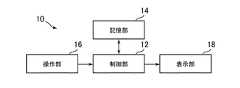
図1は、本発明の一実施形態に係る情報処理システムとして機能するゲーム装置10の構成図である。本実施形態に係るゲーム装置10は、例えば、ゲームコンソール、携帯型ゲーム端末、パーソナルコンピュータ等である。図1に示すように、本実施形態に係るゲーム装置10は、制御部12、記憶部14、操作部16、表示部18、を含んでいる。 FIG. 1 is a configuration diagram of a
制御部12は、ゲーム装置10にインストールされるプログラムに従って動作するCPU等のプログラム制御デバイスである。記憶部14は、ROMやRAM等の記憶素子やハードディスクドライブなどである。操作部16は、キーボードやマウス、あるいは家庭用ゲーム機のコントローラ等であって、ユーザの操作入力を受け付けて、その内容を示す信号を制御部12に出力する。表示部18は、液晶ディスプレイ等の表示デバイスであって、制御部12の指示に従って各種の画像を表示する。 The
なお、ゲーム装置10は、ネットワークボードなどの通信インタフェース、DVD−ROMやBlu−ray(登録商標)ディスクなどの光ディスクを読み取る光ディスクドライブ、USB(Universal Serial Bus)ポートなどを含んでいてもよい。 Note that the
本実施形態に係るゲーム装置10は、本発明を適用したプログラムを実行することにより、メモリ上に、図2に例示する仮想空間20を構築するようになっている。同図に示すように、本実施形態に係る仮想空間20は、仮想3次元空間であり、プレイヤオブジェクト22、床オブジェクト24、壁オブジェクト26、樽オブジェクト28、槍オブジェクト30、などの仮想オブジェクトが視点32とともに配置されている。 The
本実施形態では、仮想オブジェクトは複数のポリゴンにより構成されている。各ポリゴンにはテクスチャがマッピングされている。本実施形態では、ゲーム装置10のユーザは、操作部16を操作することによって、仮想空間20内においてプレイヤオブジェクト22を移動させることができるようになっている。 In this embodiment, the virtual object is composed of a plurality of polygons. A texture is mapped to each polygon. In the present embodiment, the user of the
また、本実施形態に係るゲーム装置10で実行されるプログラムでは、古典力学の法則等の物理法則をシミュレートする物理エンジンの機能が実現されている。 Further, in the program executed by the
図3は、本実施形態に係るゲーム装置10の機能ブロック図である。図3に示すように、ゲーム装置10は、機能的に、データ記憶部40、操作状態取得部42、オブジェクト配置管理部44、空間画像生成出力部46を含んでいる。データ記憶部40は、記憶部14を主として実現され、その他の要素は制御部12を主として実現される。 FIG. 3 is a functional block diagram of the
これらの機能は、情報処理システムであるゲーム装置10で、本実施形態に係るプログラムが実行されることにより実現される。このプログラムは、コンピュータ通信ネットワーク経由で通信インタフェースを介して他のコンピュータからダウンロードされてもよいし、光ディスク(例えば、CD−ROMやDVD−ROMなど)、USBメモリ等のコンピュータ読み取り可能な情報記憶媒体に格納され、そこから光ディスクドライブやUSB(Universal Serial Bus)ポートなどを介してゲーム装置10にインストールされてもよい。 These functions are realized by executing the program according to the present embodiment on the
本実施形態では、予め、データ記憶部40に、仮想空間20の構築に必要な各種データが記憶されている。データ記憶部40には、例えば、仮想空間20に配置されている仮想オブジェクトに関するポリゴンデータやテクスチャデータなどが記憶されている。 In the present embodiment, various data necessary for constructing the
また、データ記憶部40には、例えば、図4に示すような、プレイヤオブジェクト22の仮想的なスケルトンを表すスケルトンデータ50が記憶されている。スケルトンデータ50には、例えば、木構造におけるノードに対応するボーン52と、木構造におけるリンクに対応するジョイント54と、が含まれている。すなわち、本実施形態では、ジョイント54は、ボーン52同士を接続するとともに、ボーン52間の親子関係を定義している。また、本実施形態に係るスケルトンデータ50では、例えば、胴体に対応付けられるボーン52が、木構造におけるルートノードとして設定されている。以下、胴体に対応付けられるボーン52をルートボーン52aと呼ぶこととする。そして、本実施形態では、プレイヤオブジェクト22の姿勢は、複数のボーン52によって表されるスケルトンの姿勢に基づいて一意に定まるようになっている。そのため、本実施形態では、各ボーン52の位置及び向きが定まると、各ボーン52の位置及び向きに応じたプレイヤオブジェクト22のポリゴンモデルを生成することができるようになっている。また、本実施形態では、ボーン52及びジョイント54は、不可視の仮想オブジェクトである。 The
また、本実施形態では、予め、データ記憶部40に、図5に例示するラグドールデータ56も記憶されている。ラグドールデータ56は、物理エンジンによる物理シミュレーション処理の対象となるオブジェクトであるラグドールを示すデータである。また、ラグドールデータ56には、ラグドールパーツ58と、ラグドールパーツ58同士を接続するジョイント60と、を含んでいる。本実施形態では、2つのラグドールパーツ58の間は、2つのジョイント60(物理ジョイント60a及びアニメーションジョイント60b)で接続されている。また、本実施形態では、個々のラグドールパーツ58は、例えば、柱形状、カプセル形状、球形状、あるいは、これらを組み合わせた形状のいずれかをしている。また、本実施形態では、ラグドールパーツ58及びジョイント60は、不可視の仮想オブジェクトである。 In the present embodiment,
また、データ記憶部40には、各ラグドールパーツ58についての物理量(例えば、大きさ、質量、慣性モーメント(本実施形態では、慣性テンソル)、重力をかける程度、摩擦係数、風の影響を受ける程度、速度、角速度、最大速度、最大角速度、インパルス値(力積を表す値)など)を表すパラメータの値、及び、各ラグドールパーツ58の移動タイプの値も記憶されている。そして、これらの値はゲームの進行状況に応じて変更することが可能になっている。ラグドールパーツ58の移動タイプについては後述する。 Further, the
また、本実施形態では、データ記憶部40に、ラグドールパーツ58間を接続する一対のジョイント60(物理ジョイント60a及びアニメーションジョイント60bの組合せ)に対応付けられる物理量(例えば、力みなど)を表すパラメータの値も記憶されている。これらの値もゲームの進行状況に応じて変更することが可能になっている。 In the present embodiment, the parameter indicating the physical quantity (for example, force) associated with the pair of joints 60 (a combination of the physical joint 60a and the animation joint 60b) connecting the
また、本実施形態では、データ記憶部40に、仮想空間20全体に関わる物理量を表すパラメータの値も記憶されている。データ記憶部40には、例えば、仮想空間20内の位置座標に対応付けて、その位置の風速を表すパラメータの値が記憶されている。また、本実施形態では、仮想空間20全体に関わる物理量を表すパラメータの値は、所定の規則に従って、時間経過とともに変化するようになっている。 In the present embodiment, parameter values representing physical quantities related to the entire
また、本実施形態では、予め、データ記憶部40に、ボーン52とラグドールパーツ58との対応関係、並びに、スケルトンデータ50に含まれるジョイント54とラグドールデータ56に含まれる一対のジョイント60との対応関係を示すデータも記憶されている。図5に示すように、本実施形態では、ボーン52には、ラグドールパーツ58に対応付けられているものも、対応付けられていないものもある。図5の例では、左上腕、右上腕、左太もも、右太もものそれぞれを表すボーン52に対応付けられるラグドールパーツ58が存在しない。本実施形態では、ルートボーン52aに対応付けられるラグドールパーツ58をルートラグドールパーツ58aと呼ぶこととする。そして、本実施形態では、ラグドールデータ56には、ルートラグドールパーツ58aが必ず含まれている。 In this embodiment, the correspondence between the
また、本実施形態では、図5に示すように、スケルトンデータ50に含まれるジョイント54には、ラグドールデータ56に含まれる一対のジョイント60に対応付けられているものも、対応付けられていないものもある。 In the present embodiment, as shown in FIG. 5, the joint 54 included in the
また、本実施形態では、予め、データ記憶部40に、スケルトンデータ50をラグドールデータ56に変換する規則を示す変換規則データや、ラグドールデータ56をスケルトンデータ50に変換する規則を示す逆変換規則データも記憶されている。本実施形態では、例えば、データ記憶部40に変換行列Tiを表すデータが記憶されており、変換行列Tiを変換規則データとして用い、変換行列Tiの逆行列を逆変換規則データとして用いる。 In this embodiment, the
また、本実施形態では、予め、データ記憶部40に、ラグドールパーツ58に対応付けられていないボーン52について、その親のボーン52の位置及び向きに基づいて自らの位置及び向きを決定する規則を示すデータ(例えば、その親のボーン52の位置及び向きに対する相対的な位置及び向きを示すデータ)が記憶されている。本実施形態では、このデータは、ボーン52と親のボーン52との親子関係に対応付けられる規則を示していている。なお、このデータは、ボーン52の親子関係について共通にあてはめる規則を示していてもよいし、ボーン52の親子関係毎に異なる規則を示していてもよい。 Further, in the present embodiment, a rule for determining the position and orientation of the
また、本実施形態では、予め、データ記憶部40に、複数のモーション(例えば、歩く、走る、落下するなど)のそれぞれに対応付けられる、スケルトンの姿勢の変化態様を示すモーションデータも記憶されている。本実施形態では、モーションデータには、例えば、予め設定された複数のキーフレームについての、フレーム番号と、そのフレーム番号に対応付けられる、スケルトンデータ50により表されるスケルトンの姿勢(例えば、各ボーン52のローカル座標系における位置及び向き)との組合せが含まれている。また、本実施形態では、モーションデータには、モーションの識別子、及び、そのモーションに対応付けられる状態(本実施形態では、モーション駆動状態、又は、完全ラグドール状態)を示すデータも含まれている。モーション駆動状態、及び、完全ラグドール状態については後述する。また、本実施形態では、プレイヤオブジェクト22の現在のモーションを示すデータも記憶されている。 In the present embodiment, the
また、本実施形態では、予め、データ記憶部40に、例えば、コントローラの入力量が所定値を超えた場合に、「歩く」から「走る」にモーションが変化する、あるいは、プレイヤオブジェクト22に足場がない場合は、現在のモーションがどのモーションであっても「落下する」にモーションが変化する、などといった、モーションが遷移する条件を示す遷移条件データが記憶されている。また、本実施形態では、遷移条件データには、モーションが遷移する際に用いられる設定を示すデータ(例えば、遷移時に遷移前のモーションと遷移後のモーションをどのように補間するかを示すデータ、ダンピング係数(低減率)及びその発動条件を示すデータなど)が関連付けられている。ダンピング係数及びその発動条件については後述する。 In the present embodiment, the motion changes from “walking” to “running” in advance in the
本実施形態では、空間画像生成出力部46が、仮想空間20内に配置された視点32から視線方向を見た様子を表す画像(以下、空間フレーム画像と呼ぶ。)を所定時間(例えば、1/60秒)間隔で生成し、表示部18に表示出力する。 In the present embodiment, an image (hereinafter referred to as a space frame image) representing a state in which the spatial image
ここで、前フレームにおいてプレイヤオブジェクト22のモーションが遷移しなかった場合における、本実施形態に係るゲーム装置10で毎フレーム行われる(例えば、1/60秒間隔で行われる)処理の流れの一例を、図6A及び図6Bに例示するフロー図を参照しながら説明する。なお、本処理例では、予め、実行されているゲームにおけるプレイヤの現在位置(必ずしもプレイヤオブジェクト22が配置されている位置と一致していなくてもよい)と現在の向きが設定されていることとする。 Here, an example of a flow of processing that is performed every frame (for example, performed at 1/60 second intervals) in the
まず、操作状態取得部42が、操作部16の操作状態(具体的には、例えば、押下されているボタンの種類、及び、ボタンの押下量)を取得する(S101)。そして、オブジェクト配置管理部44が、本処理の開始時点におけるスケルトンの姿勢(モーション及びフレーム番号など)、S101に示す処理で取得した操作状態、及び、プレイヤの現在位置及び現在の向き、に基づいて、プレイヤオブジェクト22の仮想空間20内における変化の記述に用いられる各種パラメータの値を決定する(S102)。S102に示す処理では、オブジェクト配置管理部44は、例えば、モーションを再生すべきフレーム番号、プレイヤオブジェクト22のワールド座標系における移動量並びに回転量、及び、発生したイベントの種類、などを決定する。 First, the operation
そして、オブジェクト配置管理部44が、S102に示す処理でイベントが発生していると決定された場合には、そのイベントの種類に応じた処理を実行する(S103)。この処理の詳細については後述する。 If the object
また、オブジェクト配置管理部44は、プレイヤオブジェクト22の現在のモーション、及び、S102に示す処理で決定されたフレーム番号に基づいて、各ボーン52のローカル座標系における位置及び向き(すなわち、スケルトンの姿勢)を決定して、その決定に従うよう各ボーン52を配置する(S104)。 The object
オブジェクト配置管理部44は、具体的には、例えば、ルートボーン52aを、プレイヤの現在位置をS102に示す処理で決定された移動量だけ移動させた位置に、プレイヤの現在の向きをS102に示す処理で決定された回転量だけ回転させた向きで配置する。なお、このとき、オブジェクト配置管理部44が、ルートボーン52aの鉛直方向が、床オブジェクト24に対する法線方向に沿うように、各ボーン52の位置や向きを調整するようにしてもよい。そして、オブジェクト配置管理部44は、決定されたフレーム番号の直前、直後のキーフレームのフレーム番号に対応付けられる姿勢データを補間してなるデータに従って各ボーン52のローカル座標系における位置及び向きを決定する。そして、オブジェクト配置管理部44は、決定されるローカル座標系における位置及び向きに従うよう残りのボーン52を配置する。 Specifically, for example, the object
そして、オブジェクト配置管理部44は、データ記憶部40に記憶されている変換規則データを取得して、配置されたスケルトンと、変換規則データと、に基づいて、ラグドールパーツ58に対応付けられているボーン52について、そのボーン52に対応するラグドールパーツ58に位置及び向きを決定して、その決定に従うよう各ラグドールパーツ58を配置する(S105)。オブジェクト配置管理部44は、具体的には、例えば、配置された各ボーン52の位置及び向きを表す値に対して変換行列Tiを乗じることにより、対応するラグドールパーツ58の位置及び向きの値を決定する。 Then, the object
そして、オブジェクト配置管理部44が、S102に示す処理で決定されたパラメータの値に基づいて基準位置Pb及び基準向きDbを決定する(S106)。このとき、オブジェクト配置管理部44は、例えば、プレイヤの現在位置をS102に示す処理で決定された移動量だけ移動させた位置に対してさらにS102に示す処理で決定されたモーションの種類に基づいて決定されるオフセットだけずらした位置を基準位置Pbとして決定し、プレイヤオブジェクト22の現在の向きをS102に示す処理で決定された回転量だけ回転させた向きに対してさらにS102に示す処理で決定されたモーションの種類に基づいて決定されるオフセットだけずらした向きを基準向きDbとして決定する。 Then, the object
そして、オブジェクト配置管理部44は、代表点の位置が基準位置Pbに一致し、予め設定された前方の向きが基準向きDbに一致するよう、衝突判定用剛体オブジェクト62を仮想空間20内に配置する(S107)。そして、オブジェクト配置管理部44は、それぞれの代表点が基準位置Pb、及び、基準位置Pbに対して上、下、左、右にずらした位置に一致する5つのプロキシオブジェクト64を仮想空間20内に配置する(S108)。図7に、仮想空間20内に衝突判定用剛体オブジェクト62、及び、5つのプロキシオブジェクト64が配置されている様子の一例を示す。図7には、基準位置Pb及び基準向きDbも示されている。この段階で配置されるプロキシオブジェクト64は、あくまでも本処理例におけるプロキシオブジェクト64の候補であり、後述する処理によりこれらのうちの1つが本処理例におけるプロキシオブジェクト64として決定されることとなる。本実施形態では、5つのプロキシオブジェクト64の向きはすべて基準向きDbに一致している。本実施形態では、衝突判定用剛体オブジェクト62、並びに、プロキシオブジェクト64は、仮想空間20内に配置される楕円体形状の不可視の仮想オブジェクトである。また、本実施形態では、衝突判定用剛体オブジェクト62の重心の位置と基準位置Pbに配置されたプロキシオブジェクト64の重心の位置とは一致し、衝突判定用剛体オブジェクト62とプロキシオブジェクト64とは相似形であり、衝突判定用剛体オブジェクト62はプロキシオブジェクト64よりも大きい。 Then, the object
そして、オブジェクト配置管理部44が、プロキシオブジェクト64、衝突判定用剛体オブジェクト62、並びに、ラグドールに対して物理シミュレーション処理を実行する(S109)。このことにより、プロキシオブジェクト64、ラグドール、ラグドールや衝突判定用剛体オブジェクト62に接触している仮想オブジェクトについては、位置や向き、並びに、速度パラメータの値(本実施形態では、速度パラメータの値は3次元ベクトルで表されている。)が変化することがある。例えば、壁オブジェクト26にめりこんでいるプロキシオブジェクト64は、壁オブジェクト26の外に押し戻されることとなる。物理シミュレーション処理の詳細については後述する。 Then, the object
そして、オブジェクト配置管理部44は、プレイヤオブジェクト22の現在のモーションに対応付けられる状態を判定する(S110)。本実施形態では、例えば、「歩く」、「走る」などのモーションはモーション駆動状態に設定され、「落下する」などのモーションは完全ラグドール状態に設定されている。 Then, the object
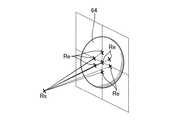
そして、モーション駆動状態である場合は、オブジェクト配置管理部44は、物理シミュレーション処理の実行後の5つのプロキシオブジェクト64の位置のうち、基準位置Pbまでの距離が最も短いプロキシオブジェクト64を、本処理例におけるプロキシオブジェクト64として決定する(S111)。この時点で、オブジェクト配置管理部44は、残りのプロキシオブジェクト64は仮想空間20から消去する。そして、図8に示すように、前フレームにおいて決定されたレイキャスト始点Rsと、プロキシオブジェクト64の代表点(例えば、重心)の位置、及び、代表点に対して所定の長さだけ前、後、左、右、上、下、にずらした位置に一致する7つのレイキャスト終点Reのそれぞれと、をつなぐ7つの線分上に、壁オブジェクト26等の他の仮想オブジェクトが存在しているか否かを判定する(S112)。7つの線分のすべてが他の仮想オブジェクトと交差する場合は(S112:Y)、プロキシオブジェクト64の位置及び向きを、前フレームにおいて決定されたプロキシオブジェクト64の位置及び向きに変更する(S113)。すなわち、プロキシオブジェクト64の位置及び向きは、前フレームにおいて決定されたプロキシオブジェクト64の位置及び向きに戻ることとなる。よって、プロキシオブジェクト64の位置及び向きは、前フレームにおいて決定されたプロキシオブジェクト64の位置及び向きのまま変更されない。また、この場合は、次フレームにおいてもレイキャスト始点Rsの位置は変わらない。 Then, in the motion drive state, the object
一方、他の仮想オブジェクトと交差しない線分が存在する場合は(S112:N)、所定の優先順位に関する規則に従って決定されるいずれかのレイキャスト終点Reを、次フレームにおけるレイキャスト始点Rsとして決定する(S114)。この場合は、プロキシオブジェクト64の位置及び向きは、S111に示す処理で決定された位置及び向きのままである。 On the other hand, if there is a line segment that does not intersect with another virtual object (S112: N), any raycast end point Re determined in accordance with a rule regarding a predetermined priority is determined as the raycast start point Rs in the next frame. (S114). In this case, the position and orientation of the
そして、S113に示す処理又はS114に示す処理が終了すると、オブジェクト配置管理部44は、プロキシオブジェクト64の位置及び向きを、次フレームにおけるプレイヤの現在位置及び現在の向きとして決定する(S115)。 When the process shown in S113 or the process shown in S114 ends, the object
一方、S110に示す処理で完全ラグドール状態であると判定された場合は、物理シミュレーション処理の実行後のルートラグドールパーツ58aの位置及び向きを、次フレームにおけるプレイヤの現在位置及び現在の向きとして決定する(S116)。 On the other hand, when it is determined in the process shown in S110 that the rag doll is in the complete rag doll state, the position and orientation of the root
そして、S115に示す処理又はS116に示す処理が終了すると、オブジェクト配置管理部44は、物理シミュレーション処理の実行後のラグドールに基づいて、各ラグドールパーツ58に対応するボーン52の位置及び向きを決定して、その決定に従うよう各ボーン52を配置する(S117)。ここで、オブジェクト配置管理部44は、ルートボーン52aから、親のボーン52から子のボーン52への順序で、S117に示す処理を実行する。そして、オブジェクト配置管理部44は、データ記憶部40に記憶されている逆変換規則データを取得して、ラグドールパーツ58が対応付けられているボーン52については、物理シミュレーション処理の実行後のラグドールパーツ58の位置及び向きと、逆変換規則データと、に基づいて、ボーン52の位置及び向きを決定する。オブジェクト配置管理部44は、具体的には、例えば、ラグドールパーツ58の位置及び向きを表す値に対して変換行列Tiの逆行列を乗じることにより、対応するボーン52の位置及び向きの値を決定する。 When the process shown in S115 or the process shown in S116 ends, the object
一方、オブジェクト配置管理部44は、ラグドールパーツ58が対応付けられていないボーン52については、親のボーン52の位置及び向きに対する相対的な位置及び向きを示すデータと、S117に示す処理で決定された親のボーン52の位置及び向きと、に基づいて、ラグドールパーツ58に対応付けられていないボーン52の位置及び向きを決定する。このようにして、ラグドールパーツ58が対応付けられていないボーン52については、親のボーン52の位置又は向きの変化に応じて、自らの位置又は向きが変化することとなる。 On the other hand, the object
そして、オブジェクト配置管理部44は、S117に示す処理で決定された各ボーン52の位置及び向きに基づいて、描画の対象となるプレイヤオブジェクト22を仮想空間20内に配置する(S118)。そして、オブジェクト配置管理部44は、配置後のプレイヤオブジェクト22、及び、S101に示す処理で取得した操作部16の操作状態に基づいて、次フレームにおけるモーションを決定する(S119)。ここでは、例えば、配置後のプレイヤオブジェクト22に基づいて決定される、足場があるか否かを示す情報、足場の傾斜角、各ラグドールに設定されているインパルス値、及び、遷移条件データに基づいて、次フレームにおけるモーションを決定する。 Then, the object
そして、空間画像生成出力部46が、視点32から視線方向を見た様子を表す空間フレーム画像を生成し、表示部18に表示出力する(S120)。 Then, the spatial image generation /
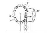
ここで、図9に示す、樽オブジェクト28と衝突判定用剛体オブジェクト62、及び、樽オブジェクト28とプロキシオブジェクト64が衝突する様子を例に、S109に示す物理シミュレーション処理について説明する。 Here, the physical simulation process shown in S109 will be described by taking, as an example, a state in which the
まず、オブジェクト配置管理部44は、衝突していると判定される仮想オブジェクト対を特定する。本実施形態では、図9に示すように、各仮想オブジェクトには、仮想オブジェクトを覆う不可視の衝突判定領域66が設定されており、オブジェクト配置管理部44は、衝突判定領域66が接触している、あるいは、重なっている仮想オブジェクト対を衝突している仮想オブジェクト対として特定する。図9の例では、プロキシオブジェクト64と、樽オブジェクト28と、が衝突しており、衝突判定用剛体オブジェクト62と、樽オブジェクト28と、が衝突していると判定される。なお、本実施形態では、予め、衝突判定用剛体オブジェクト62とプロキシオブジェクト64との衝突判定は行われないように設定されている。 First, the object
そして、オブジェクト配置管理部44は、図9に示す樽オブジェクト28とプロキシオブジェクト64のそれぞれに設定されている質量パラメータの値、及び、速度パラメータの値、を取得する。そして、オブジェクト配置管理部44は、取得した値、及び、プロキシオブジェクト64が樽オブジェクト28と接触している程度(めりこんでいる程度)を表す指標、に基づいて、プロキシオブジェクト64の速度パラメータの値の変化量を算出する。そして、オブジェクト配置管理部44は、算出された変化量だけ速度パラメータの値を変化させた上で、変化後の速度パラメータの値に基づいて特定される移動量(例えば、変化後の速度パラメータの値を所定倍した移動量)だけプロキシオブジェクト64を移動させる。また、オブジェクト配置管理部44は、図9に示す樽オブジェクト28とプロキシオブジェクト64のそれぞれに設定されている慣性テンソルパラメータの値、角速度パラメータの値を取得する。そして、オブジェクト配置管理部44は、取得した値、及び、プロキシオブジェクト64が樽オブジェクト28に接触している程度(めりこんでいる程度)を表す指標、に基づいて、プロキシオブジェクト64の角速度パラメータの値の変化量を算出する。そして、オブジェクト配置管理部44は、算出された変化量だけ角速度パラメータの値を変化させた上で、変化後の角速度パラメータの値に基づいて特定される回転量(例えば、変化後の角速度パラメータの値を所定倍した回転量)だけプロキシオブジェクト64を回転させる。 Then, the object
また、オブジェクト配置管理部44は、図9に示す樽オブジェクト28と衝突判定用剛体オブジェクト62のそれぞれに設定されている質量パラメータの値、及び、速度パラメータの値を取得する。そして、オブジェクト配置管理部44は、取得した値、及び、衝突判定用剛体オブジェクト62が樽オブジェクト28に接触している程度(めりこんでいる程度)を表す指標、に基づいて、樽オブジェクト28の速度パラメータの値の変化量を算出する。そして、オブジェクト配置管理部44は、算出された変化量だけ速度パラメータの値を変化させた上で、変化後の速度パラメータの値に基づいて特定される移動量(例えば、変化後の速度パラメータの値を所定倍した移動量)だけ樽オブジェクト28を移動させる。また、オブジェクト配置管理部44は、樽オブジェクト28と衝突判定用剛体オブジェクト62のそれぞれに設定されている慣性テンソルパラメータの値、角速度パラメータの値を取得する。そして、オブジェクト配置管理部44は、取得した値、及び、衝突判定用剛体オブジェクト62が樽オブジェクト28に接触している程度(めりこんでいる程度)を表す指標、に基づいて、樽オブジェクト28の角速度パラメータの値の変化量を算出する。そして、オブジェクト配置管理部44は、算出された変化量だけ角速度パラメータの値を変化させた上で、変化後の角速度パラメータの値に基づいて特定される回転量(例えば、変化後の角速度パラメータの値を所定倍した回転量)だけ樽オブジェクト28を回転させる。 Further, the object
本実施形態では、公知の物理エンジンの機能を用いて、上述の変化量の算出を行っている。図10を参照しながら、物理エンジンにおける速度パラメータの値の算出手法の一例を説明する。ここでは、図10に示すように、左の仮想オブジェクト(質量パラメータの値:mA、速度パラメータの値:vA(右向きを正))と、右の仮想オブジェクト(質量パラメータの値:mB、速度パラメータの値:vB(右向きを正))とが衝突した場合を考える。ここでは、仮想オブジェクト同士が接触している程度(めりこんでいる程度)を表す指標として、仮想オブジェクトの重心をつなぐ直線に沿った方向での、仮想オブジェクトが重なっている長さdを用いることとする。 In the present embodiment, the above-described change amount is calculated using a function of a known physical engine. An example of a method for calculating the value of the speed parameter in the physical engine will be described with reference to FIG. Here, as shown in FIG. 10, the left virtual object (mass parameter value: mA, velocity parameter value: vA (rightward is positive)) and the right virtual object (mass parameter value: mB, velocity parameter). A value of vB (positive to the right)) collides. Here, the length d where the virtual objects overlap in the direction along the straight line connecting the centers of gravity of the virtual objects is used as an index representing the degree to which the virtual objects are in contact with each other (the degree of depression). And
すると、衝突後の左の仮想オブジェクトの速度vA’は、vA’=vA−(mB/(mA+mB))×(α(vA−vB)+βd)という数式により算出され、衝突後の右の仮想オブジェクトの速度vB’は、vB’=vB+(mA/(mA+mB))×(α(vA−vB)+βd)という数式により算出される。ここで、α、βは所定の調整値を表している。 Then, the velocity vA ′ of the left virtual object after the collision is calculated by an equation of vA ′ = vA− (mB / (mA + mB)) × (α (vA−vB) + βd), and the right virtual object after the collision is calculated. The velocity vB ′ is calculated by the following equation: vB ′ = vB + (mA / (mA + mB)) × (α (vA−vB) + βd). Here, α and β represent predetermined adjustment values.
このように、物理エンジンでは、衝突した仮想オブジェクトそれぞれの速度パラメータの値の変化量は、質量パラメータの値の比(質量パラメータの値の和に対する衝突相手の質量パラメータの値の割合)や、相対速度や、仮想オブジェクト同士が接触している程度(めりこんでいる程度)などに基づいて決定されることとなる。同様に、物理エンジンでは、衝突した仮想オブジェクトそれぞれの角速度パラメータの値の変化量は、仮想オブジェクトそれぞれの慣性テンソルの値や、相対角速度や、仮想オブジェクト同士が接触している程度(めりこんでいる程度)などに基づいて決定されることとなる。 In this way, in the physics engine, the amount of change in the speed parameter value of each collision virtual object is the ratio of the mass parameter value (ratio of the mass parameter value of the collision partner to the sum of the mass parameter values) or relative It is determined based on the speed, the degree to which the virtual objects are in contact with each other (degree of indentation), and the like. Similarly, in the physics engine, the amount of change in the value of the angular velocity parameter of each collided virtual object is the degree of inertia tensor value, relative angular velocity of each virtual object, or the degree to which the virtual objects are in contact (indented). Degree) and the like.
図9における仮想オブジェクト同士が接触している程度(めりこんでいる程度)としては、例えば、所定の投影面に投影した際における、仮想オブジェクトの重心の投影点をつなぐ直線に沿った方向での、衝突判定領域66が重なっている長さを用いることが考えられる。そして、本実施形態では、この長さが長ければ長いほど上述の変化量が大きくなるようになっている。例えば、衝突判定用剛体オブジェクト62と樽オブジェクト28との衝突における物理シミュレーション処理では、図9に示されている長さd1が用いられ、プロキシオブジェクト64と樽オブジェクト28との衝突における物理シミュレーション処理では図9に示されている長さd2が用いられる。 The degree to which the virtual objects in FIG. 9 are in contact with each other (the degree to which they are recessed) is, for example, in a direction along a straight line connecting the projection points of the center of gravity of the virtual object when projected onto a predetermined projection plane It is conceivable to use a length in which the
また、本実施形態では、衝突判定用剛体オブジェクト62には、ゲームにおいて他の仮想オブジェクトとの関係でプレイヤオブジェクト22として設定するのに妥当な質量パラメータや慣性テンソルパラメータの値が設定される。具体的には、例えば、プレイヤオブジェクト22と他の仮想オブジェクトとの質量比や慣性テンソル比が、ゲームにおけるプレイヤと他のオブジェクトとの質量比や慣性テンソル比と整合する値が設定される。一方、プロキシオブジェクト64には、ゲームにおいて他の仮想オブジェクトとの関係でプレイヤオブジェクト22として設定するのに妥当な質量パラメータや慣性テンソルパラメータの値よりも充分大きな値が質量パラメータや慣性テンソルパラメータの値として設定される。 In the present embodiment, the collision determination
また、本実施形態では、プロキシオブジェクト64に設定される質量パラメータや慣性テンソルパラメータの値が衝突相手となる仮想オブジェクトの属性に基づいて決定される。本実施形態では、例えば、衝突相手となる仮想オブジェクトに設定されている質量パラメータや慣性テンソルパラメータの値が大きくなればなるほど、質量パラメータや慣性テンソルパラメータの値が大きくなるよう、プロキシオブジェクト64の質量パラメータや慣性テンソルパラメータの値が設定される。例えば、衝突相手となる仮想オブジェクトに設定されている質量パラメータや慣性テンソルパラメータの値に比例した値がプロキシオブジェクト64の質量パラメータや慣性テンソルパラメータの値として設定される。また、例えば、衝突相手となる仮想オブジェクトの種別(例えば、壁オブジェクト26であるのか樽オブジェクト28であるのか、など)に応じて、プロキシオブジェクト64に設定される質量パラメータや慣性テンソルパラメータの値が決定されるようにしてもよい。 Further, in the present embodiment, the values of the mass parameter and inertia tensor parameter set for the
本実施形態では、衝突相手の仮想オブジェクトの物理量(速度等)の変化を算出する基礎となる、プレイヤオブジェクト22に対応付けられるパラメータの値(ここでは、衝突判定用剛体オブジェクト62に設定されている質量パラメータや慣性テンソルパラメータの値)と、プレイヤオブジェクト22の物理量(速度等)の変化を算出する基礎となる、プレイヤオブジェクト22に対応付けられるパラメータの値(ここでは、プロキシオブジェクト64に設定されている質量パラメータや慣性テンソルパラメータの値)が異なる。そのため、丸め誤差等の影響によって物理エンジンによる算出結果が不安定にならないよう、パラメータの値を設定することで、物理エンジンによる算出結果を安定させることができることとなり、その結果、衝突する様子の表現のリアリティがなくなってしまう可能性が低減することとなる。 In the present embodiment, the parameter value associated with the player object 22 (here, the collision determination
また、本実施形態では、衝突判定用剛体オブジェクト62が、プロキシオブジェクト64よりも大きくなるよう設定されるため、衝突相手の仮想オブジェクトが、衝突判定用剛体オブジェクト62とは衝突するが、プロキシオブジェクト64とは衝突しないということが起こりうる。そして、衝突判定用剛体オブジェクト62には、ゲームにおいて他の仮想オブジェクトとの関係でプレイヤオブジェクト22として設定するのに妥当な質量パラメータや慣性テンソルパラメータの値が設定されるので、衝突相手の仮想オブジェクトが移動する際の表現(例えば、吹き飛ぶような表現)が的確なものとなることが期待される。また、プロキシオブジェクト64には、妥当な質量パラメータや慣性テンソルパラメータの値よりも充分大きな値(例えば、衝突相手の仮想オブジェクトに設定されている質量パラメータや慣性テンソルパラメータの値に比例した値)が質量パラメータや慣性テンソルパラメータの値として設定されるので、質量パラメータや慣性テンソルパラメータの値が大きな仮想オブジェクト(例えば、壁オブジェクト26)とプロキシオブジェクト64が衝突したと判定された場合に、丸め誤差の影響を受けずにプロキシオブジェクト64がきちんと停止するようになることも期待される。 In the present embodiment, since the collision determination
また、本実施形態では、衝突相手となる仮想オブジェクトの属性に応じた、プロキシオブジェクト64の質量パラメータや慣性テンソルパラメータの値が可能であるので、パラメータの値の設定のバリエーションが広がり、仮想空間20内における仮想オブジェクト同士が衝突する様子の表現のバリエーションを広げることができる。 Further, in this embodiment, since the value of the mass parameter or the inertia tensor parameter of the
また、本実施形態では、S111に示す処理で、複数のプロキシオブジェクト64の候補のうち、基準位置Pbまでの距離が最も短いプロキシオブジェクト64が、本処理例におけるプロキシオブジェクト64として決定されるので、プレイヤオブジェクト22を進めようとしているところ付近にプレイヤオブジェクト22を進めることができ、細かい凹凸のある壁オブジェクト26にひっかかる、床オブジェクト24に設けられている小さな段差の影響を受け、プレイヤオブジェクト22が思いの外高く飛んでしまう、などといった、リアリティのない画像表現となるおそれを低減することができることとなる。また、さらに、S112〜S114に示す処理で、S111に示す処理で決定されたプロキシオブジェクト64内の所定数の点のそれぞれと、前フレームのプロキシオブジェクト64内の点と、をつなぐ線分上に仮想オブジェクトが存在している場合には、プロキシオブジェクト64が移動しないこととなるので、プロキシオブジェクト64が仮想オブジェクトをすり抜けてしまうおそれを低減することができることとなる。 In the present embodiment, the
また、本実施形態では、オブジェクト配置管理部44は、各仮想オブジェクトに設定されている、風の影響を受ける程度を示すパラメータの値と、仮想オブジェクトが配置されている位置に対応付けられている風速パラメータの値と、に基づいて、仮想オブジェクトの位置や向きをさらも変化させる。 In the present embodiment, the object
ラグドールパーツ58と他の仮想オブジェクトとの衝突についても、ただし、ジョイント60による拘束条件があるなどといった相違点はあるが、基本的には上述と同様の物理シミュレーション処理が行われる。なお、本実施形態では、モーションの種類に基づいて、各ラグドールパーツ58の移動タイプの値が決定される。移動タイプの値としては、例えば、キーフレーム、位置制御、速度制御、ジョイント制御、位置制御(ワンウェイ)、速度制御(ワンウェイ)、ジョイント制御(ワンウェイ)などが挙げられる。移動タイプの値がキーフレームであるラグドールパーツ58は、他の仮想オブジェクトと衝突しても物理シミュレーション処理の結果位置が変化することはない。移動タイプの値が位置制御であるラグドールパーツ58は、モーションの種類とフレーム番号との組合せに基づいて決定される位置に配置された上で物理シミュレーション処理が実行されることとなる。移動タイプの値が速度制御であるラグドールパーツ58は、モーションの種類とフレーム番号との組合せに基づいて決定される位置と現在位置との差分に基づいてラグドールパーツ58の速度パラメータの値が設定された上で物理シミュレーション処理が実行されることとなる。また、移動タイプが上述のワンウェイに該当するものについては、衝突相手から影響を受けるが、衝突相手に影響を与えないこととなる。 The collision between the
移動タイプの値がジョイント制御であるラグドールパーツ58は、モーションの種類とフレーム番号との組合せに基づいて決定される、親のラグドールパーツ58との間の角度がアニメーションジョイント60bの角度として設定される。また、移動タイプの値がジョイント制御であるラグドールパーツ58は、所定の物理的制約条件が物理ジョイント60aに設定される。そして、このようなジョイント60の設定がされた上で、物理シミュレーション処理が実行されることとなる。ここで、物理シミュレーション処理では、アニメーションジョイント60bの角度は変化せず、物理ジョイント60aの角度は物理的制約条件を満たす範囲で可変となる。そして、本実施形態では、ジョイント60に設定されている力みパラメータの値に応じた比率でアニメーションジョイント60bでの物理シミュレーション処理の結果と物理ジョイント60aでの物理シミュレーション処理の結果とがブレンド(例えば、力みパラメータの値が100%であれば、アニメーションジョイント60bの比率が100%となり、力みパラメータの値が0%であれば、物理ジョイント60aの比率が100%となる。)された結果が、物理シミュレーション処理の最終結果として取り扱われることとなる。 The
そして、上述のS117の示す処理で説明したように、本実施形態では、物理シミュレーション処理の実行後のラグドールパーツ58については、逆変換規則データに基づいて対応するボーン52に変換される。一方、一部のボーン52については、対応するラグドールパーツ58が設定されておらず、親のボーン52の位置及び向きに応じてボーン52の位置及び向きが設定される。このように、本実施形態では、物理シミュレーション処理の対象となるラグドールパーツ58の総数は、ボーン52の総数よりも少なくなっている。よって、すべてのボーン52について対応するラグドールパーツ58が存在する場合と比較して、本実施形態では、S109に示す物理シミュレーション処理でのゲーム装置10の計算負荷を低減することができることとなる。 In the present embodiment, the
また、例えば、S119に示す処理でモーションが変化した際に、データ記憶部40に記憶されているデータが示す設定に従って、プレイヤオブジェクト22の位置や向きの決定が行われるようにしてもよい。具体的には、例えば、遷移前のモーションにおける上述のS118に示す処理の結果と、遷移前のモーションにおける上述のS118に示す処理の結果と、を補間することによって得られる結果が、描画の対象となるプレイヤオブジェクト22の配置が決定されるようにしてもよい。 Further, for example, when the motion changes in the process shown in S119, the position and orientation of the
本実施形態では、モーションが遷移した場合には、遷移条件データに関連付けられているデータが示す設定に応じた修正が、上述のS101〜S120に示す処理に加えられることとなる。例えば、数フレームにわたって、遷移前のモーションでの処理の結果と、遷移後のモーションでの処理の結果とを、遷移条件データに関連付けられているデータが示す設定に応じたブレンド比率で補間した処理結果が、最終的な処理結果として取り扱われる。また、本実施形態では、数フレームの間に、徐々に、遷移前のモーションでの処理の結果が占めるブレンド比率が低くなり、遷移後のモーションでの処理の結果が占めるブレンド比率が高くなるようになっている。 In this embodiment, when a motion transitions, correction according to the setting indicated by the data associated with the transition condition data is added to the processing shown in S101 to S120 described above. For example, over several frames, the result of processing in the motion before the transition and the result of processing in the motion after the transition are interpolated with the blend ratio according to the setting indicated by the data associated with the transition condition data The result is treated as the final processing result. In the present embodiment, the blend ratio occupied by the processing result in the motion before the transition gradually decreases and the blend ratio occupied by the processing result in the motion after the transition gradually increases during several frames. It has become.
また、本実施形態では、前フレームまでモーション駆動状態であった仮想オブジェクトが、完全ラグドール状態に遷移するということが考えられる。この場合、本実施形態では、オブジェクト配置管理部44は、モーション駆動状態での処理結果の速度パラメータの値を用いて、完全ラグドール状態での物理シミュレーション処理を行うこととなる。このとき、本実施形態では、モーションの遷移に対応付けられている上述の発動条件を満足する場合(例えば、速度パラメータの値の、仮想空間20に設定された鉛直方向上向きの成分が所定値以上である場合)には、完全ラグドール状態になった際の物理シミュレーション処理後の速度パラメータの値に対して、さらに、予め、仮想空間20に設定された鉛直方向上向き成分について、モーションの遷移に対応付けられている上述のダンピング係数の値(例えば、設定されている値は0から1までの間のいずれかの実数)を乗じることで、最終的な速度パラメータの値を決定する。こうすれば、最終的な速度パラメータの値であるベクトルの向きが、ダンピング係数の値が乗じられる前の速度パラメータの値であるベクトルの向きに対して鉛直方向下向きにずれることととなる。例えば、2つ前のフレームにおけるプレイヤの現在位置から1つ前のフレームにおけるプレイヤの現在位置に向かう向きに速度パラメータが表す速度ベクトルが設定されている場合に、その向きよりも鉛直方向下向きに速度パラメータが表す速度ベクトルが変更されることとなる。そのため、完全ラグドール状態に遷移した際に、リアリティがない事態が発生すること(例えば、プレイヤオブジェクト22が上方に吹っ飛んでしまうこと)を防ぐことができることとなる。 Further, in the present embodiment, it can be considered that a virtual object that has been in a motion driving state until the previous frame transitions to a complete ragdoll state. In this case, in this embodiment, the object
ここで、上述のS103に示す処理における、発生したイベントの種類に応じた処理の一例について図11を参照しながら説明する。ここでは、例えば、プレイヤオブジェクト22が槍オブジェクト30を所持するというイベントが発生したこととする。そして、図11は、上述のイベントが発生した際の、衝突判定用剛体オブジェクト62やプロキシオブジェクト64などをプレイヤオブジェクト22の上方から見た様子の一例を示す図である。 Here, an example of processing according to the type of event that has occurred in the processing shown in S103 will be described with reference to FIG. Here, for example, it is assumed that an event has occurred in which the
図11に示すように、上述のイベントが発生した際には、オブジェクト配置管理部44は、プロキシオブジェクト64の大きさを、プレイヤオブジェクト22と槍オブジェクト30の両方を包含する形状になるよう大きくするとともに、槍オブジェクト30に設定されていた衝突判定領域66を消去する。そして、オブジェクト配置管理部44は、大きくなったプロキシオブジェクト64を覆う衝突判定領域66を、プロキシオブジェクト64と槍オブジェクト30の両方に対応付けられる衝突判定領域66として設定する。このようにして、プレイヤオブジェクト22と槍オブジェクト30の両方を包含する閉領域が、プロキシオブジェクト64と槍オブジェクト30の両方に対応付けられる衝突判定領域66として設定されることとなる。また、本実施形態では、図11に示すように、プロキシオブジェクト64の形状の変化に伴い、変化後のプロキシオブジェクト64を包含する形状となるよう衝突判定用剛体オブジェクト62、及び、衝突判定用剛体オブジェクト62を覆う衝突判定領域66の形状も変化する。 As shown in FIG. 11, when the above-described event occurs, the object
そして、本実施形態では、プロキシオブジェクト64を覆う衝突判定領域66が、他の仮想オブジェクトの衝突判定領域66と接触した(あるいは、重なった)際には、他の仮想オブジェクトと、プロキシオブジェクト64と、が衝突したと判定される。また、衝突判定用剛体オブジェクト62を覆う衝突判定領域66が、他の仮想オブジェクトの衝突判定領域66と接触した(あるいは、重なった)際には、他の仮想オブジェクトと、衝突判定用剛体オブジェクト62と、が衝突したと判定される。なお、ここでは、プロキシオブジェクト64や衝突判定用剛体オブジェクト62の衝突判定領域66が、他の仮想オブジェクトの衝突判定領域66と接触した(あるいは、重なった)際に、プロキシオブジェクト64や衝突判定用剛体オブジェクト62が、他の仮想オブジェクトと衝突したと判定される代わりに、他の仮想オブジェクトと槍オブジェクト30とが衝突したと判定されるようにしても、他の仮想オブジェクトとプレイヤオブジェクト22とが衝突したと判定されるようにしてもよい。 In this embodiment, when the
このようにして、本実施形態では、プレイヤオブジェクト22が槍オブジェクト30を所持するというイベントが発生した時期以降については、プレイヤオブジェクト22と槍オブジェクト30との間での衝突判定処理が実行されないようにすることができる。 Thus, in the present embodiment, the collision determination process between the
また、オブジェクト配置管理部44は、図11に示すように、プロキシオブジェクト64を、その一部に扇形柱を含む形状となるようにしてもよい。オブジェクト配置管理部44は、この扇形柱の断面の扇形の中心角θをプレイヤオブジェクト22に設定されている角速度パラメータの値に基づいて決定する。具体的には、例えば、角速度パラメータの値に1フレームの時間間隔を乗じた値が扇形の中心角θの値として設定される。図11の例では2つの扇形柱が示されており、それぞれの扇形柱の断面の扇形の中心は、プレイヤオブジェクト22と槍オブジェクト30位置関係に基づいて決定される位置(例えば、プレイヤオブジェクト22の近傍)に設定されている。また、それぞれの扇形柱の断面の扇形について、扇形の中心と槍オブジェクト30の先端までの線分と、その線分をプレイヤオブジェクト22の回転方向後方だけ上述の回転角θだけ回転させた線分と、が扇形の半径となっている。 Further, as shown in FIG. 11, the object
このようにして、例えば、槍オブジェクト30のような細長い仮想オブジェクトを振り回すような動作が仮想空間20内で行われるような場面でも、図11に示すように、1フレームで移動する槍オブジェクト30の軌跡上に壁オブジェクト26等の仮想オブジェクトが存在するような場面でも、プロキシオブジェクト64と壁オブジェクト26とが衝突し、衝突判定用剛体オブジェクト62と壁オブジェクト26とが衝突したと判定することができることとなる。 In this way, for example, even in a situation where an operation of swinging a long and narrow virtual object such as the
なお、オブジェクト配置管理部44は、プロキシオブジェクト64を、仮想空間20内をプレイヤオブジェクト22及び槍オブジェクト30が所定時間内に移動する長さ(例えば、1フレームにおいて移動する長さ)を奥行きとする、その一部に直方体を含むその一部に含む形状となるようにしてもよい。 Note that the object
また、オブジェクト配置管理部44は、例えば、プレイヤオブジェクト22が槍オブジェクト30を所持するというイベントの発生以降、プロキシオブジェクト64、及び、プロキシオブジェクト64を覆う衝突判定領域66の形状を徐々に大きくするようにしてもよい。 Further, the object
なお、本発明は上述の実施形態に限定されるものではない。 In addition, this invention is not limited to the above-mentioned embodiment.
例えば、オブジェクト配置管理部44は、モーションの遷移に対応付けられている上述の発動条件を満足する場合に、仮想空間20に設定された鉛直方向上向き成分以外の速度成分についても、速度パラメータの値に、所定の値を乗じることで、最終的な速度パラメータの値を低減したり、角速度パラメータの値に所定の値を乗じることで、最終的な角速度パラメータの値を低減したりするようにしてもよい。 For example, when the object
また、例えば、上述のS112に示す処理において、前フレームにおいて決定されたレイキャスト始点Rsと、プロキシオブジェクト64の代表点に対して所定の長さだけ前、又は、上にずらした位置に一致するレイキャスト終点のそれぞれと、をつなぐ2つの線分については、線分上に他の仮想オブジェクトが存在しているか否かの判定を行わないようにしてもよい。 Further, for example, in the processing shown in S112 described above, the raycast start point Rs determined in the previous frame matches the position shifted by a predetermined length before or above the representative point of the
また、例えば、衝突判定用剛体オブジェクト62の大きさが、衝突していると判定される仮想オブジェクトの種別に応じて変わるようにしてもよい。例えば、衝突相手の仮想オブジェクトが吹き飛ばした方がよりよい仮想オブジェクトであればあるほど、衝突判定用剛体オブジェクト62の大きさを大きくするようにしてもよい。 Further, for example, the size of the collision determination
また、上述のS111に示す処理において、物理シミュレーション処理の実行後の5つのプロキシオブジェクト64の位置のうち、特定方向の座標値(例えば、鉛直方向の座標値)が、基準位置Pbの特定方向の座標値(例えば、鉛直方向の座標値)に最も近いプロキシオブジェクト64を、上述の処理例におけるプロキシオブジェクト64として決定してもよい。 Further, in the process shown in S111 described above, among the five proxy objects 64 after the physical simulation process is executed, the coordinate value in the specific direction (for example, the coordinate value in the vertical direction) is the one in the specific direction of the reference position Pb. The
また、本実施形態では、衝突した仮想オブジェクトそれぞれの速度パラメータの値を用いて、物理シミュレーション処理を実行しているが、衝突した仮想オブジェクトそれぞれの速度パラメータの値の代わりに、一方の仮想オブジェクトに対する他方の仮想オブジェクトの相対速度、などのような、2つの仮想オブジェクトの移動速度の関係に関する他の情報を用いて、物理シミュレーション処理を実行しても構わない。 In this embodiment, the physical simulation process is executed using the velocity parameter value of each collided virtual object. However, instead of the velocity parameter value of each collided virtual object, one virtual object is used. You may perform a physical simulation process using the other information regarding the relationship of the moving speed of two virtual objects, such as the relative speed of the other virtual object.
また、本実施形態をゲーム装置10以外の情報処理システム(例えば、シミュレーションシステムや画像処理システムなど)に応用してもよい。また、上記の具体的な数値や文字列や図面中の具体的な数値や文字列は例示であり、これらの数値や文字列には限定されない。 Further, the present embodiment may be applied to an information processing system (for example, a simulation system or an image processing system) other than the
10 ゲーム装置、12 制御部、14 記憶部、16 操作部、18 表示部、20 仮想空間、22 プレイヤオブジェクト、24 床オブジェクト、26 壁オブジェクト、28 樽オブジェクト、30 槍オブジェクト、32 視点、40 データ記憶部、42 操作状態取得部、44 オブジェクト配置管理部、46 空間画像生成出力部、50 スケルトンデータ、52 ボーン、52a ルートボーン、54 ジョイント、56 ラグドールデータ、58 ラグドールパーツ、58a ルートラグドールパーツ、60 ジョイント、60a 物理ジョイント、60b アニメーションジョイント、62 衝突判定用剛体オブジェクト、64 プロキシオブジェクト、66 衝突判定領域。 10 game devices, 12 control units, 14 storage units, 16 operation units, 18 display units, 20 virtual spaces, 22 player objects, 24 floor objects, 26 wall objects, 28 barrel objects, 30 basket objects, 32 viewpoints, 40 data storage Part, 42 operation state acquisition part, 44 object arrangement management part, 46 aerial image generation output part, 50 skeleton data, 52 bone, 52a root bone, 54 joint, 56 rag doll data, 58 rag doll part, 58a root rag doll part, 60 joint , 60a physical joint, 60b animation joint, 62 rigid object for collision determination, 64 proxy object, 66 collision determination area.
Claims (8)
Translated fromJapanese移動対象のオブジェクトの現在位置に基づいて、前記移動対象のオブジェクトの移動先の基準となる基準位置、及び、前記移動対象のオブジェクトの移動先の候補となる複数の候補位置を決定する決定手段、
前記複数の候補位置のうちの少なくとも一部を、当該候補位置と仮想空間内に配置されている他のオブジェクトの位置との関係に基づいて変更する候補位置変更手段、
少なくとも一部について前記候補位置変更手段により位置が変更された前記複数の候補位置のうち前記基準位置から最も近い位置に、前記移動対象のオブジェクトの位置を変更する移動対象オブジェクト位置変更手段、
として前記コンピュータを機能させることを特徴とするプログラム。A program that causes a computer to function as an information processing system that controls the movement of an object arranged in a virtual space,
A determination unit that determines a reference position that is a reference of a movement destination of the object to be moved and a plurality of candidate positions that are candidates of a movement destination of the object to be moved based on a current position of the object to be moved;
Candidate position changing means for changing at least a part of the plurality of candidate positions based on the relationship between the candidate position and the position of another object arranged in the virtual space;
Moving target object position changing means for changing the position of the moving target object to a position closest to the reference position among the plurality of candidate positions whose positions have been changed by the candidate position changing means for at least a part thereof;
A program for causing the computer to function as:
前記オブジェクト位置変更手段は、少なくとも1つの前記線分について線分上に他のオブジェクトが存在しないと前記判定手段により判定される場合は、前記最も近い位置に前記移動対象のオブジェクトの位置を変更し、そうでない場合は、前記移動対象のオブジェクトの位置を変更しない、
ことを特徴とする請求項1に記載のプログラム。Determination means for determining whether or not another object exists on a line segment connecting each of the plurality of positions set with the closest position as a reference and the position where the object to be moved is arranged , Further functioning the computer as
The object position changing means changes the position of the object to be moved to the closest position when the determining means determines that there is no other object on the line segment for at least one of the line segments. Otherwise, do not change the position of the object to be moved,
The program according to claim 1.
前記移動手段は、所定の条件を満足する場合に、前記移動対象のオブジェクトに設定される速度ベクトルを前記仮想空間に予め設定された向きにずらした速度ベクトルに基づいて算出される位置に前記移動対象のオブジェクトをさらに移動させる、
ことを特徴とする請求項1又は2に記載のプログラム。Moving means for further moving the object to be moved to a position calculated based on a velocity vector set for the object to be moved after the position of the object to be moved is changed by the moving object position changing means. , Further functioning the computer as
The moving means moves to a position calculated based on a speed vector obtained by shifting a speed vector set for the object to be moved in a direction set in advance in the virtual space when a predetermined condition is satisfied. Move the target object further,
The program according to claim 1 or 2, characterized by the above-mentioned.
ことを特徴とする請求項3に記載のプログラム。The moving means further moves the object to be moved to a position calculated based on a velocity vector obtained by shifting a speed vector set for the object to be moved in a predetermined direction as a downward downward direction in the virtual space. Move,
The program according to claim 3.
ことを特徴とする請求項1から4のいずれか一項に記載のプログラム。Causing thecomputer to further function as an image generation unit that generates an image representing a state in which the virtual space in which the object is arranged is viewed from a viewpoint set in the virtual space;
The program according to any one of claims 1 to 4, wherein:
移動対象のオブジェクトの現在位置に基づいて、前記移動対象のオブジェクトの移動先の基準となる基準位置、及び、前記移動対象のオブジェクトの移動先の候補となる複数の候補位置を決定する決定手段、
前記複数の候補位置のうちの少なくとも一部を、当該候補位置と仮想空間内に配置されている他のオブジェクトの位置との関係に基づいて変更する候補位置変更手段、
少なくとも一部について前記候補位置変更手段により位置が変更された前記複数の候補位置のうち前記基準位置から最も近い位置に、前記移動対象のオブジェクトの位置を変更する移動対象オブジェクト位置変更手段、
として前記コンピュータを機能させることを特徴とするプログラムを記憶したコンピュータ読み取り可能な情報記憶媒体。A computer-readable information storage medium storing a program for causing a computer to function as an information processing system for controlling movement of an object arranged in a virtual space,
A determination unit that determines a reference position that is a reference of a movement destination of the object to be moved and a plurality of candidate positions that are candidates of a movement destination of the object to be moved based on a current position of the object to be moved;
Candidate position changing means for changing at least a part of the plurality of candidate positions based on the relationship between the candidate position and the position of another object arranged in the virtual space;
Moving target object position changing means for changing the position of the moving target object to a position closest to the reference position among the plurality of candidate positions whose positions have been changed by the candidate position changing means for at least a part thereof;
A computer-readable information storage medium storing a program that causes the computer to function as:
移動対象のオブジェクトの現在位置に基づいて、前記移動対象のオブジェクトの移動先の基準となる基準位置、及び、前記移動対象のオブジェクトの移動先の候補となる複数の候補位置を決定する決定手段と、
前記複数の候補位置のうちの少なくとも一部を、当該候補位置と仮想空間内に配置されている他のオブジェクトの位置との関係に基づいて変更する候補位置変更手段と、
少なくとも一部について前記候補位置変更手段により位置が変更された前記複数の候補位置のうち前記基準位置から最も近い位置に、前記移動対象のオブジェクトの位置を変更する移動対象オブジェクト位置変更手段と、
を含むことを特徴とする情報処理システム。An information processing system for controlling movement of an object arranged in a virtual space,
Determining means for determining, based on the current position of the object to be moved, a reference position that is a reference for the destination of the object to be moved, and a plurality of candidate positions that are candidates for the destination of the object to be moved; ,
Candidate position changing means for changing at least some of the plurality of candidate positions based on the relationship between the candidate positions and the positions of other objects arranged in the virtual space;
Movement target object position changing means for changing the position of the object to be moved to a position closest to the reference position among the plurality of candidate positions whose positions have been changed by the candidate position changing means for at least a part;
An information processing system comprising:
情報処理システムに含まれる決定手段が、移動対象のオブジェクトの現在位置に基づいて、前記移動対象のオブジェクトの移動先の基準となる基準位置、及び、前記移動対象のオブジェクトの移動先の候補となる複数の候補位置を決定する決定ステップと、
前記情報処理システムに含まれる候補位置変更手段が、前記複数の候補位置のうちの少なくとも一部を、当該候補位置と仮想空間内に配置されている他のオブジェクトの位置との関係に基づいて変更する候補位置変更ステップと、
前記情報処理システムに含まれる移動対象オブジェクト位置変更手段が、少なくとも一部について前記候補位置変更ステップにより位置が変更された前記複数の候補位置のうち前記基準位置から最も近い位置に、前記移動対象のオブジェクトの位置を変更する移動対象オブジェクト位置変更ステップと、
を含むことを特徴とする情報処理方法。
An information processing method for controlling movement of an object arranged in a virtual space,
Based on the current position of the object to be moved, the determination means included in the information processing system becomes a reference position that serves as a reference for the destination of the object to be moved and a candidate for the destination of the object to be moved. A determining step for determining a plurality of candidate positions;
Candidate position changing means included in the information processing system changes at least a part of the plurality of candidate positions based on a relationship between the candidate position and the position of another object arranged in the virtual space. A candidate position changing step to
The movement target object position changing means included in the information processing system has the movement target object at a position closest to the reference position among the plurality of candidate positions whose positions have been changed at least in part by the candidate position changing step. A moving object position changing step for changing the position of the object;
An information processing method comprising:
Priority Applications (2)
| Application Number | Priority Date | Filing Date | Title |
|---|---|---|---|
| JP2011118457AJP5396432B2 (en) | 2011-05-26 | 2011-05-26 | Program, information storage medium, information processing system, and information processing method |
| US13/438,262US9050538B2 (en) | 2011-05-26 | 2012-04-03 | Collision detection and motion simulation in game virtual space |
Applications Claiming Priority (1)
| Application Number | Priority Date | Filing Date | Title |
|---|---|---|---|
| JP2011118457AJP5396432B2 (en) | 2011-05-26 | 2011-05-26 | Program, information storage medium, information processing system, and information processing method |
Publications (2)
| Publication Number | Publication Date |
|---|---|
| JP2012247952A JP2012247952A (en) | 2012-12-13 |
| JP5396432B2true JP5396432B2 (en) | 2014-01-22 |
Family
ID=47468348
Family Applications (1)
| Application Number | Title | Priority Date | Filing Date |
|---|---|---|---|
| JP2011118457AActiveJP5396432B2 (en) | 2011-05-26 | 2011-05-26 | Program, information storage medium, information processing system, and information processing method |
Country Status (1)
| Country | Link |
|---|---|
| JP (1) | JP5396432B2 (en) |
Family Cites Families (2)
| Publication number | Priority date | Publication date | Assignee | Title |
|---|---|---|---|---|
| JP3643512B2 (en)* | 2000-02-28 | 2005-04-27 | 日本電信電話株式会社 | Three-dimensional cooperative virtual space realization method, apparatus therefor, and recording medium recording program therefor |
| EP2266673B1 (en)* | 2009-06-24 | 2018-12-12 | Nintendo Co., Ltd. | Computer readable storage medium and information processing apparatus |
- 2011
- 2011-05-26JPJP2011118457Apatent/JP5396432B2/enactiveActive
Also Published As
| Publication number | Publication date |
|---|---|
| JP2012247952A (en) | 2012-12-13 |
Similar Documents
| Publication | Publication Date | Title |
|---|---|---|
| US9050538B2 (en) | Collision detection and motion simulation in game virtual space | |
| JP3696216B2 (en) | Three-dimensional video game apparatus, control method of virtual camera in three-dimensional video game, program and recording medium | |
| US8909506B2 (en) | Program, information storage medium, information processing system, and information processing method for controlling a movement of an object placed in a virtual space | |
| US20230334744A1 (en) | Method and apparatus for generating walk animation of virtual role, device and storage medium | |
| JP4125760B2 (en) | Video game processing apparatus, video game processing method, and video game processing program | |
| JP5118220B2 (en) | Motion modeling apparatus and method, and program | |
| JP3926307B2 (en) | Three-dimensional image drawing apparatus and method, program, and recording medium | |
| JP2007300974A (en) | Program, information storage medium, and image generation system | |
| CN101534916B (en) | Game device, game device control method | |
| JP7697034B2 (en) | Method and apparatus for displaying virtual gun shooting, computer device, and computer program | |
| JP5143883B2 (en) | Image processing apparatus, image processing program, and image processing method | |
| JP2012247953A (en) | Program, information storage medium, information processing system and information processing method | |
| US7621812B2 (en) | Game system and game program | |
| JP5784985B2 (en) | Program, information storage medium, information processing system, and information processing method | |
| JP6905568B2 (en) | Game program, game processing method and information processing device | |
| JP5396432B2 (en) | Program, information storage medium, information processing system, and information processing method | |
| JP2008264276A (en) | GAME PROGRAM, GAME DEVICE, AND STORAGE MEDIUM | |
| JP2012247951A (en) | Program, information storage medium, information processing system and information processing method | |
| JP2001276414A (en) | Game device and information memory medium | |
| JP2018128851A (en) | Program, object layout system and object layout method | |
| JP5328841B2 (en) | Program, information storage medium, information processing system, and information processing method | |
| JP5043224B2 (en) | PROGRAM, INFORMATION STORAGE MEDIUM, AND GAME DEVICE | |
| JP4467590B2 (en) | Drawing apparatus, drawing method, and drawing program | |
| CN107050848B (en) | Somatosensory game implementation method and device based on body area network | |
| JP6576544B2 (en) | Information processing apparatus, information processing method, and computer-readable storage medium |
Legal Events
| Date | Code | Title | Description |
|---|---|---|---|
| A977 | Report on retrieval | Free format text:JAPANESE INTERMEDIATE CODE: A971007 Effective date:20130527 | |
| A131 | Notification of reasons for refusal | Free format text:JAPANESE INTERMEDIATE CODE: A131 Effective date:20130604 | |
| A521 | Written amendment | Free format text:JAPANESE INTERMEDIATE CODE: A523 Effective date:20130723 | |
| A977 | Report on retrieval | Free format text:JAPANESE INTERMEDIATE CODE: A971007 Effective date:20130805 | |
| TRDD | Decision of grant or rejection written | ||
| A01 | Written decision to grant a patent or to grant a registration (utility model) | Free format text:JAPANESE INTERMEDIATE CODE: A01 Effective date:20131001 | |
| A61 | First payment of annual fees (during grant procedure) | Free format text:JAPANESE INTERMEDIATE CODE: A61 Effective date:20131021 | |
| R150 | Certificate of patent or registration of utility model | Ref document number:5396432 Country of ref document:JP Free format text:JAPANESE INTERMEDIATE CODE: R150 Free format text:JAPANESE INTERMEDIATE CODE: R150 | |
| R250 | Receipt of annual fees | Free format text:JAPANESE INTERMEDIATE CODE: R250 | |
| R250 | Receipt of annual fees | Free format text:JAPANESE INTERMEDIATE CODE: R250 | |
| R250 | Receipt of annual fees | Free format text:JAPANESE INTERMEDIATE CODE: R250 | |
| R250 | Receipt of annual fees | Free format text:JAPANESE INTERMEDIATE CODE: R250 | |
| R250 | Receipt of annual fees | Free format text:JAPANESE INTERMEDIATE CODE: R250 | |
| R250 | Receipt of annual fees | Free format text:JAPANESE INTERMEDIATE CODE: R250 |