JP5396372B2 - Data center - Google Patents
Data centerDownload PDFInfo
- Publication number
- JP5396372B2 JP5396372B2JP2010253513AJP2010253513AJP5396372B2JP 5396372 B2JP5396372 B2JP 5396372B2JP 2010253513 AJP2010253513 AJP 2010253513AJP 2010253513 AJP2010253513 AJP 2010253513AJP 5396372 B2JP5396372 B2JP 5396372B2
- Authority
- JP
- Japan
- Prior art keywords
- rack
- row
- racks
- rows
- rack row
- Prior art date
- Legal status (The legal status is an assumption and is not a legal conclusion. Google has not performed a legal analysis and makes no representation as to the accuracy of the status listed.)
- Expired - Fee Related
Links
Images


Landscapes
- Central Air Conditioning (AREA)
Description
Translated fromJapanese本発明は、多くのサーバ等のコンピュータ関連機器が収容されているデータセンターに関し、特にコンピュータ機器を収容したコンピュータ室内の温度ムラの発生を抑制して、適切な温度管理を可能とするデータセンターに関する。 The present invention relates to a data center in which computer-related equipment such as a large number of servers is accommodated, and more particularly, to a data center that enables appropriate temperature management by suppressing occurrence of temperature unevenness in a computer room housing computer equipment. .
従来、複数のサーバ等のコンピュータ関連機器を収容したラックを、空調システムを有するコンピュータ室に収容するデータセンターが知られている。コンピュータ室内では、複数のラックを一列に並べ形成したラック列を平行に並べ、ラック列間の通路のうち空調システムによって冷却用空気が供給されるコールドアイルと、コンピュータ関連機器から温められた空気が排出されるホットアイルとが形成されている。例えば、特許文献1には、コールドアイルの冷却用空気とホットアイルの暖められた空気とが混じり合わないようにして、空調効率を上げる発明が記載されている。 2. Description of the Related Art Conventionally, a data center that houses a rack that houses computer-related equipment such as a plurality of servers in a computer room having an air conditioning system is known. In the computer room, rack rows formed by arranging a plurality of racks in a row are arranged in parallel, and the cold aisle supplied with cooling air by the air conditioning system in the path between the rack rows and the warm air from the computer-related equipment A hot aisle to be discharged is formed. For example, Patent Document 1 describes an invention that increases air conditioning efficiency so that cold aisle cooling air and hot aisle air are not mixed.
また、冷却用空気は、床下空間から床面に設けられた冷気供給口から床上空間に供給することが、例えば特許文献2に記載されている。 Further, for example,
ラック列を平行に配置し、コールドアイルCとホットアイルHを形成しても、適切な温度管理を行うことは容易ではない。例えば、床下空間から床上空間へ冷却用空気を供給する場合、床下空間内のケーブルなどの障害物によって冷却用空気がコンピュータ室内に均等に行き渡らないことがあり、このようなことが原因でコンピュータ室内に温度ムラが生じることがある。 Even if the rack rows are arranged in parallel and the cold aisle C and the hot aisle H are formed, it is not easy to perform appropriate temperature control. For example, when cooling air is supplied from the underfloor space to the above-floor space, the cooling air may not be evenly distributed in the computer room due to an obstruction such as a cable in the underfloor space. Temperature unevenness may occur.
そこで、本発明の目的は、コンピュータ室内の温度ムラの発生を抑制して、適切な温度管理を可能とするデータセンターを提供することである。 SUMMARY OF THE INVENTION An object of the present invention is to provide a data center capable of suppressing temperature unevenness in a computer room and performing appropriate temperature management.
本発明の一つの実施態様に従うデータセンターは、一以上のコンピュータ関連機器を収納した複数のラックを一列に並べて配置して構成されたラック列を複数、互いに平行に配置してなる複数のラック列と、前記ラック列が配置される床面下方に設けられた床下空間に対して前記ラック列を構成する複数のラックが並べられる方向と略平行な方向に流れるように冷却用空気を供給する冷気供給口、前記床下空間から床面上に向かって前記冷却用空気を吹き出す床面吹き出し口、および、前記ラック列の上方の天井に設けられ前記ラック列周辺の熱を冷却することで前記冷却用空気が温められてなる温排気が吸い込まれる排気口を備える空調システムと、を有するデータセンターであって、前記一以上のコンピュータ関連機器をネットワークに接続するための通信用ケーブルと、前記ラック列を構成する複数のラックが並べられた方向と略垂直方向に前記通信用ケーブルを配線して天井から吊り下げて保持する通信用ケーブル保持具と、前記ラック列の端部に配置され、前記通信用ケーブルを前記通信用ケーブル保持具から前記床下空間へ配線するダミーラックと、を有し、前記通信用ケーブルは、前記ダミーラックから延びて当該ダミーラックが配置されているラック列の複数のラックに対して、これらラックが並べられた方向と略平行になるよう前記床下空間内に配置されていることを特徴とする。 A data center according to one embodiment of the present invention includes a plurality of rack rows in which a plurality of rack rows configured by arranging a plurality of racks storing one or more computer-related devices in a row are arranged in parallel with each other. And cooling air that supplies cooling air so as to flow in a direction substantially parallel to a direction in which a plurality of racks constituting the rack row are arranged with respect to an underfloor space provided below the floor surface on which the rack row is disposed A supply port, a floor surface outlet from which the cooling air is blown out from the underfloor space toward the floor surface, and the cooling by providing heat around the rack row provided in the ceiling above the rack row An air-conditioning system having an exhaust port through which hot exhaust air is warmed, and the one or more computer-related devices are connected to a network. A communication cable for continuing, and a communication cable holder that holds the communication cable in a direction substantially perpendicular to the direction in which the plurality of racks constituting the rack row are arranged and suspended from the ceiling, and A dummy rack that is disposed at an end of the rack row and that routes the communication cable from the communication cable holder to the underfloor space, and the communication cable extends from the dummy rack and extends to the dummy rack. The plurality of racks in the rack row in which the racks are arranged are arranged in the underfloor space so as to be substantially parallel to the direction in which the racks are arranged.
好適な実施形態では、前記ラック列の、前記ダミーラックとは反対の端部に配置された分電盤と、前記分電盤に電力を供給する幹電源ケーブルと、各分電盤から延びてその分電盤が配置されているラック列のコンピュータ関連機器へ電力を供給する複数の第1の枝電源ケーブル、及びそのラック列と隣り合うラック列のコンピュータ関連機器へ電力を供給する複数の第2の枝電源ケーブルと、前記ラック列を構成する複数のラックが並べられた方向と略垂直方向に、前記枝電源ケーブルを配線して天井から吊り下げて保持する電源ケーブル保持具と、を有し、前記電源ケーブル保持具が、隣り合うラック列間において前記第2の枝電源ケーブルを保持し、前記第1の枝電源ケーブルと、前記電源ケーブル保持具を介して隣のラック列から伸びた第2の枝電源ケーブルが、ラックが並べられた方向と略平行になるように前記ラック列の上方に配置されているようにしていてもよい。 In a preferred embodiment, a distribution board disposed at an end of the rack row opposite to the dummy rack, a main power cable for supplying power to the distribution board, and extending from each distribution board. A plurality of first branch power cables that supply power to the computer-related equipment in the rack row in which the distribution board is arranged, and a plurality of second power cables that supply power to the computer-related equipment in the rack row adjacent to the
好適な実施形態では、互いに向かい合う2列のラック列の間の床面は複数の矩形板をラック列と平行に延びるように並べてなる板列を少なくとも2列配置して構成され、前記2列の板列は、前記冷気供給口となる複数の孔が形成された開孔板と全面板状の板とが交互に配置されて構成されていてもよい。 In a preferred embodiment, the floor surface between two rows of rack rows facing each other is configured by arranging at least two plate rows in which a plurality of rectangular plates are arranged so as to extend in parallel with the rack rows, and the two rows. The plate row may be configured by alternately arranging aperture plates in which a plurality of holes serving as the cold air supply ports are formed and full plate plates.
好適な実施形態では、各ラックは、その前面および背面が複数の孔を有するプレートで構成されていてもよい。 In a preferred embodiment, each rack may be composed of a plate having a plurality of holes on its front and back.
好適な実施形態では、各ラックは、前記通信用ケーブルを上下方向に延伸させた状態で前記ラックフレームに沿って保持する留め具を有していてもよい。 In a preferred embodiment, each rack may have a fastener that holds the communication cable along the rack frame in a state where the cable is extended in the vertical direction.
以下、本発明の一実施形態に係るデータセンターについて、図面を参照して説明する。 Hereinafter, a data center according to an embodiment of the present invention will be described with reference to the drawings.
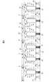
図1は、本実施形態に係るデータセンター1の全体構成図(平面図)である。データセンター1は、同図に示すように、多数のコンピュータ関連機器をまとめて収納するためのコンピュータ室2を有する。コンピュータ室2内には、複数のラック列10,10,・・・が互いに平行に配置されている。各ラック列10は、共通の構成を有している。例えば、ラック列10は、一以上のコンピュータ関連機器を収納した複数のラックを一列に並べて配置して構成されている。ここで、コンピュータ関連機器は、例えば、サーバ、ネットワーク機器及びストレージ装置などを含む。 FIG. 1 is an overall configuration diagram (plan view) of a data center 1 according to the present embodiment. As shown in the figure, the data center 1 has a
図1の例では、互いに平行に並べた複数のラック列10,10,・・・により構成されるラック列群が2つあるが、ラック列群の数は任意である。ラック列群内で、各ラック列10の間隔は等間隔でもよいし、各ラック列10の長さは同じでもよい。なお、コンピュータ室2内にいくつのラック列10を収容するかは任意である。 In the example of FIG. 1, there are two rack row groups constituted by a plurality of
ラック列10の一方の端部には分電盤200、他方の端部にはダミーラック300がそれぞれ配置されている。ラック列群内では、分電盤200が配置されている側、及びダミーラック300が配置されている側は統一されている。分電盤200及びダミーラック300は、いずれか一方のみが配置されていてもよい。 A
分電盤200には、コンピュータ室2外に設けられた上位の分電盤50から幹電源ケーブル16によって電力が供給される。幹電源ケーブル16は、例えば床下空間22内に配線される(図3参照)。分電盤200から、各ラック100内のコンピュータ関連機器に対して枝電源ケーブル17が配線される。 Power is supplied to the
ここで、信頼性向上のため、電源は2系統(例えばA系統とB系統)が用意されている。そして、あるラック列Aの分電盤200には幹電源ケーブル16によってA系統の電力が供給され、隣り合うラック列Bの分電盤200には幹電源ケーブル16によってB系統の電力が供給される。ラック列A及びBの分電盤200は、それぞれラック列A及びBの双方のコンピュータ関連機器に対して枝電源ケーブル17により電力を供給する。つまり、枝電源ケーブル17には、各分電盤200から延びてその分電盤200が配置されているラック列10のコンピュータ関連機器へ電力を供給する複数の第1の枝電源ケーブル17A、及びそのラック列10と隣り合うラック列10のコンピュータ関連機器へ電力を供給する複数の第2の枝電源ケーブル17Bとがある。 Here, in order to improve reliability, two power sources (for example, A system and B system) are prepared. Then, the A system power is supplied to the
コンピュータ室2の天井には、ケーブルを配線するためのラダー12,14が吊り下げられている。
ラダー12は、隣り合うラック列10間で枝電源ケーブル17を配線するために用いられる。つまり、ラダー12は、隣り合うラック列間において、分電盤200間で配線される第2の枝電源ケーブル17Bを保持する。ラダー12は、ラック列10を構成する複数のラック100が並べられた方向と略垂直方向に配置されている部分を有し、ラック列10の端部に設けられた分電盤200の上方を通るように配置されている。 The
第1の枝電源ケーブル17Aと、ラダー12を介して隣のラック列10から伸びた第2の枝電源ケーブル17Bが、ラック列10内でラックが並べられた方向と略平行になるようにラック列10の上方に配置されている。 The rack is such that the first
ラダー14は、ラック内のコンピュータ関連機器をネットワークに接続するための通信用ケーブル18を保持する保持具である。ラダー14は、ラック列10を構成する複数のラック100が並べられた方向と略垂直方向に配置されている部分を有し、各ダミーラック300の近傍を通るように配置されている。通信用ケーブル18は、コンピュータ室2外で図示しないネットワーク機器と接続されている。コンピュータ室2内に引き込まれた通信用ケーブル18は、ラダー14上を通って各ダミーラック300まで配線される。 The
データセンター1は、さらに、コンピュータ室2の室温をコントロールするめの空調システムを備える。図2及び図3を用いてこの空調システムについて説明する。 The data center 1 further includes an air conditioning system for controlling the room temperature of the
図2は、コンピュータ室2の断面及びコンピュータ室2内の空気の流れ(矢印で示す)を模式的に示す図である。 FIG. 2 is a diagram schematically showing a cross section of the
平行に配置された各ラック列10は、互いにその前面10A及び背面10Bがそれぞれ向き合うように配置され、ラック列の間は通路となっている。各ラック列10を構成するラックの内部に収容されているコンピュータ関連機器は、空冷を行うために前面10A側から吸気し、背面10B側へ排気する。つまり、同図のように配置することで、互いに隣り合うラック列10同士の吸気を行う面と排気を行う面とがそれぞれ向き合っている。このとき、吸気する前面10Aが向き合っている通路に所定の温度に冷却された冷却用空気を供給することで、各コンピュータ関連機器を効率的に冷却できる。排気する背面10Bが向き合っている通路には、コンピュータ関連機器によって温められた空気が排出される。つまり、前面10Aが向かい合っている通路にコールドアイルCが形成され、背面10Bが向かい合っている通路にホットアイルHが形成される。 The
また、図2に示すように、コンピュータ室2の床面20の下方には床下空間22が設けられている。 As shown in FIG. 2, an
図3は、床下空間22の構成図(平面図)である。同図に示すように、床下空間22には、冷却用空気を供給する冷気供給口24が設けられている。冷気供給口24は、コンピュータ室2の壁面近辺に複数設けられている。冷気供給口24は、例えば、平行に並べられたラック列10の間の通路の位置に配置してもよく、さらには、コールドアイルCの位置に配置してもよい。なお、同図では、コンピュータ室2の一つの壁面側にのみ冷気供給口24が設けられているが、これと対向する壁面側にも冷気供給口24を設けてもよい。 FIG. 3 is a configuration diagram (plan view) of the
また、床下空間22では、コンピュータ室2外に設けられた上位の分電盤50から、各ラック列10の分電盤200へ幹電源ケーブル16が配線されている。幹電源ケーブル16は、例えば、ラック列10内のラックが並ぶ方向と直行する方向に、分電盤200の真下あたりを通って配線されている。 In the
冷気供給口24から吹き出される冷却用空気の吹き出し方向Wは、ラック列10を構成するラック100が並べられている方向である。すなわち、床下空間22において、冷却用空気はコンピュータ室2の壁面から中心へ向けて、ラック列10を構成するラック100が並ぶ方向に流れる。 The blowing direction W of the cooling air blown out from the cold
図2に戻ると、床面20には、床下空間22から床面20の上方に向かって冷却用空気を吹き出す一以上の床面吹き出し口26が設けられている。床面吹き出し口26は、コールドアイルCに設置され、ホットアイルHには設置されない。また、コンピュータ室2の天井30には一以上の排気口32が設けられている。排気口32は、特に、ホットアイルHの上方に設置されるようにしてもよい。排気口32は、コンピュータ室2外へ排気するための排気通路34につながっている。 Returning to FIG. 2, the
これにより、冷気供給口24から供給された冷却用空気が床面吹き出し口26からラック列10の間(コールドアイルC)に流れ込む。ラック列10を構成するラック内に収容されているコンピュータ関連機器が、コールドアイルC側の冷却用空気を吸気して、これによって冷却される。その一方で、コンピュータ関連機器によって温められた空気はホットアイルH側へ排気される。温められた空気は上方へ上り、天井30に設けられた排気口32から吸い出され、排気通路34を通ってコンピュータ室2外へ排気される。 Thereby, the cooling air supplied from the cold
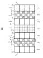
図4は、ラック列10の構成を詳細に示す図である。 FIG. 4 is a diagram showing the configuration of the
同図に示すように、ラック列10は、複数のラック100が横一列に並んで構成されている。同図では、一つのラック列10を5つのラック100で構成しているが、一ラック列あたりのラック数は任意である。 As shown in the figure, the
ラック列10内では、すべてのラック100がそれぞれの前面及び背面を同じ側へ向けている。ここで、ラック列10を構成する各ラック10のサイズは統一されているので、前面、背面及び上面の面がすべて揃っている。 In the
また、ラック列10の一方の端部に分電盤200が、他方の端部にダミーラック300が、それぞれ配置されている。つまり、一つのラック列10に対して分電盤200及びダミーラック300がそれぞれ一つずつ割り当てられている。 Further, the
分電盤200の下方の床下空間220には、分電盤50から伸びた幹電源ケーブル16が配線されている。そして、電源ケーブル16は、各分電盤200に接続されている。 A trunk
分電盤200の上方にはラダー12が配置されている。ラダー12により、ラック列10間の第2の枝電源ケーブル17Bが配線される。分電盤200から同じラック列10内のコンピュータ関連機器へ電力を供給する第1の枝電源ケーブル17Aと、ラダー12を介して隣のラック列から伸びた第2の枝電源ケーブル17Bが、ラック100が並べられた方向と略平行になるようにラック列10の上方に配置されている。分電盤200から伸びる枝電源ケーブル17は多数ある。つまり、分電盤200は、少数の幹電源ケーブル16で電力の供給を受けて、多数の枝電源ケーブル17で各ラック10内及び隣り合うラック10内のコンピュータ関連機器に電力を供給する。従って、分電盤200をラック列10の隣りに配置することにより、本数が多い枝電源ケーブル17を長い距離引き回す必要がなく、効率的に配線を行うことができる。 A
ダミーラック300は、内部が空洞で断面が矩形形状の筒体である。つまり、ダミーラック300の上面及び下面は開放され、それぞれ、通信用ケーブルの入口310及び出口320が形成されている。ダミーラック300の下面と接する床面20には、通信用ケーブル導入口21が設けられている。 The
ダミーラック300の上方にはラダー14が配置されている。ラダー14により、コンピュータ室2外から引き込まれた通信用ケーブル18がダミーラック300の上面の通信用ケーブル入口310からその内部へ導かれる。通信用ケーブル18は、ダミーラック300の内部を通過し、下面の通信用ケーブル出口320及び床面20の通信用ケーブル導入口21を通って、床下空間22へ配線される。通信用ケーブル18は、ダミーラック300から延びてダミーラック300が配置されているラック列10の複数のラック100に対して、これらラック100が並べられた方向と略平行になるよう床下空間22内に配置されている。 A
ここで、図2及び図3を参照すると、同図においても、床下空間22内で、通信用ケーブル18が各ラック列10においてラック100が並べられた方向と略平行に配線されていることが示されている。つまり、通信用ケーブル18が配線されている方向は冷気供給口24から吹き出される冷却用空気の吹き出し方向Wと一致する。これにより、床下空間22内の冷却用空気の流れが通信用ケーブル18によって阻害されることを最小限に抑制できる。 Here, referring to FIGS. 2 and 3, also in the figure, the
各ラック100に収容されるコンピュータ関連機器の消費電力(発熱量)の合計が、全ラック100について略均等になるようにしてもよい。ラック100ごとの消費電力にばらつきがあると、コンピュータ室2の温度ムラが生じやすい。コンピュータ室2は、所定の上限温度以下になるように温度管理がなされる必要がある。そのため、コンピュータ室2内に温度ムラがあると、相対的に高温のエリアを所定温度以下まで冷却する必要があるため、相対的に温度が低い一部のエリアは過冷却され、冷却効率が悪化する。つまり、ラック100単位の消費電力をできるだけ均等に保つことにより、コンピュータ室2内の温度ムラを抑制し、コンピュータ室2を効率的に冷却することができる。 The total power consumption (heat generation amount) of the computer-related devices accommodated in each
しかしながら、ラック100単位の消費電力を完全に同じにすることは難しい。そこで、各ラック100に収容されるコンピュータ関連機器の消費電力に応じて、ラック列10内でのラック100の配置を決めてもよい。例えば、相対的に消費電力の多いラック100をラック列10の中央近辺に配置し、相対的に消費電力の少ないラック100をラック列10の端に配置してもよい。ラック列10端部において、ホットアイルHの暖気がコールドアイルCに流入したときの影響を最小限にするためである。 However, it is difficult to make the power consumption of 100 rack units completely the same. Therefore, the arrangement of the
ラック列10単位の消費電力も略均等になるようにしてもよい。すなわち、ラック列10を構成するすべてのラック100に収容されるコンピュータ関連機器の消費電力の合計が、各ラック列10でほぼ等しくなるようにしてもよい。さらには、所定数のラック列10を単位エリアとして、そのエリアでの消費電力が略均等になるようにしてもよい。すなわち、各単位エリア内のラック列10の消費電力の合計がほぼ等しくなるように配置する。これらは、いずれも、コンピュータ室内の温度ムラを抑制する効果がある。 The power consumption in units of 10 rack rows may be substantially equal. That is, the total power consumption of the computer-related devices accommodated in all the
図5は、床面20の構造を示す。 FIG. 5 shows the structure of the
床面20は、複数の矩形(例えば正方形)の床板25(25A,25B)が敷き詰められて構成されている。平行に配置されたラック列10間の通路には、床板25がラック列10と平行に並べられている。ラック列10間の通路に並べられた床板25が形成する板列27は少なくとも2列以上(同図では3列)ある。 The
床板25には全面が板状で開口を有しない通常板25Aと、複数の孔が形成された開孔板25Bとがある。この開孔板25Bによって、上述した床面吹き出し口26が形成される。つまり、開孔板25Bを通って床下空間22から床面の上に吹き出してくる。従って、開孔板25BはコールドアイルCにのみ設置され、ホットアイルHには設置されない。 The floor plate 25 includes a
また、隣り合う2列の板列27においては、通常板25Aと開孔板25Bとが交互に配置されるようにしてもよい。すなわち、同図に示すように、ある板列27で通常板25Aが設置されているとき、隣の板列27の同じ行には開孔板25Bが設置される。また、これとは逆に、ある板列27の開孔板25Bに対しては、隣の板列の同じ行には通常板25Aが設置される。その結果、同図に示すように、床面20は、通常板25Aと開孔板25Bとにより市松模様が形成される。 Further, in the two adjacent rows of
通常板25Aと開孔板25Bの配置は市松模様以外にも、例えば、所定枚数の床板25であるパターンを形成し、そのパターンをラック列10においてラック100が並ぶ方向(図中上下方向)に繰り返すようにしてもよい。例えば、3×3の9枚の床板25で形成したパターンであって、一つの対角線方向に3枚の開孔板25Bを配置したパターンを繰り返すようにしてもよい。 In addition to the checkerboard pattern, for example, the
図6はラック100の正面側斜視図であり、図7はラック100の背面側斜視図である。以下、図6及び図7を参照して、ラック100の構成について説明する。 FIG. 6 is a front perspective view of the
ラック100は、ラック本体110と、前面、背面、両サイド、上面及び下面のプレート120,130,140,150,160,170とを有する。ラック本体110は、その幅、奥行き及び高さが所定のサイズに統一されている。ラック本体110には、サーバ、ネットワーク機器などのコンピュータ関連機器のユニットが複数収容可能である。サーバを収容するラック100とネットワーク機器を収容するラック100とは、互いに分けてもよい。その際、サーバを収容するラック100は、下面プレート170を装着しなくてもよい。 The
ラック本体110及び各プレート120,130,140,150,160,170は、例えば、いずれも金属製である。また、必ずしも照度が十分でないコンピュータ室2内での作業のし易さを考慮して、ラック本体110及び各プレート120,130,140,150,160,170の色は、白またはシルバーなどの明るい色としてもよい。 The
前面プレート120は、ラック本体110の前面全体をカバーするプレートである。前面プレート120は、正面から見て右側の端部でヒンジ121によりラック本体110に取り付けられている。つまり、前面プレート120は、右端を回転軸として開閉可能である。また、前面プレート120は、ラック本体110から完全に取り外し可能(着脱可能)である。前面プレート120は、複数の孔122を有する。プレート全体の面積に対する孔122の面積の比率(開口率)は、例えば70%以上である。 The
背面プレート130は、ラック本体110の背面全体をカバーするプレートである。背面プレート130は、ラック本体110に対して着脱可能に取り付けられる。背面プレート130は、図7に示すように、前面プレート120同様にヒンジ131を介してラック本体110に取り付けてもよい。つまり、背面プレート130も、右端を回転軸として開閉可能としてもよい。背面プレート130は、前面プレート120同様に複数の孔132を有し、その開口率は例えば70%以上である。前面プレート120と背面プレート130の開口率を同じにしてもよい。 The
図7に示すように、ラック100の背面側では、枝電源ケーブル17と通信用ケーブル18とがラック100内で配線されている。通信用ケーブル18は、上下方向に延伸させた状態で留め具112により、ラック本体110に沿ってまとめて保持されている。通信用ケーブル18は、特に本数が多いのでまとめて、ラック本体110に沿って配線しておくことで、ラック100内に熱がこもりことを防止できるともに、背面からの作業がやりやすくなる。 As shown in FIG. 7, branch power cables 17 and
左右の側面プレート140,150は、ラック本体110の各側面全体をカバーするプレートであり、各側面に着脱可能に取り付けられている。これにより、ラック側面からの空気の流出入を防止する。隣接するラックが存在する側の側面には、側面プレート140,150にブラシ付きのケーブル通過口が設けられていてもよい。これにより、ラック側面からの空気の流出入を防止しつつ、ケーブルの配線を行うことができる。 The left and
上面プレート160は、ラック本体110の上面全体をカバーするプレートである。上面プレート160は、ケーブル通過口161を有する。ラック100上面からの空気の流出入を防止するとともに、塵やホコリの進入を防止する。上面プレート160の上には枝電源ケーブル17が通っていて、枝電源ケーブル17はケーブル通過口161からラック以内に収容される。 The
下面プレート170は、ネットワーク機器を収納するラックのときに使用する。例えば、ネットワーク機器には側面から吸気するタイプのものがあり、このタイプのネットワーク機器に対しては、下面プレート170の開閉により、ラック100内への冷却用空気の供給を調整する。 The
上述した本発明の実施形態は、本発明の説明のための例示であり、本発明の範囲をそれらの実施形態にのみ限定する趣旨ではない。当業者は、本発明の要旨を逸脱することなしに、他の様々な態様で本発明を実施することができる。 The above-described embodiments of the present invention are examples for explaining the present invention, and are not intended to limit the scope of the present invention only to those embodiments. Those skilled in the art can implement the present invention in various other modes without departing from the gist of the present invention.
1 データセンター
2 コンピュータ室
10 ラック列
12,14 ラダー
16 幹電源ケーブル
17 枝電源ケーブル
18 通信用ケーブル
20 床面
22 床下空間
24 冷気供給口
25 床板
25A 通常板
25B 開孔板
100 ラック
200 分電盤
300 ダミーラック
C コールドアイル
H ホットアイル
DESCRIPTION OF SYMBOLS 1
Claims (5)
Translated fromJapanese前記ラック列が配置される床面下方に設けられた床下空間に対して前記ラック列を構成する複数のラックが並べられる方向と略平行な方向に流れるように冷却用空気を供給する冷気供給口、前記床下空間から床面上に向かって前記冷却用空気を吹き出す床面吹き出し口、および、前記ラック列の上方の天井に設けられ前記ラック列周辺の熱を冷却することで前記冷却用空気が温められてなる温排気が吸い込まれる排気口を備える空調システムと、を有するデータセンターであって、
前記一以上のコンピュータ関連機器をネットワークに接続するための通信用ケーブルと、
前記ラック列を構成する複数のラックが並べられた方向と略垂直方向に前記通信用ケーブルを配線して天井から吊り下げて保持する通信用ケーブル保持具と、
前記ラック列の端部に配置され、前記通信用ケーブルを前記通信用ケーブル保持具から前記床下空間へ配線するダミーラックと、を有し、
前記通信用ケーブルは、前記ダミーラックから延びて当該ダミーラックが配置されているラック列の複数のラックに対して、これらラックが並べられた方向と略平行になるよう前記床下空間内に配置されていることを特徴とするデータセンター。A plurality of rack rows configured by arranging a plurality of racks containing one or more computer-related devices in a row, and a plurality of rack rows arranged in parallel with each other;
A cold air supply port for supplying cooling air to flow in a direction substantially parallel to a direction in which a plurality of racks constituting the rack row are arranged with respect to an underfloor space provided below the floor surface on which the rack row is disposed The floor air outlet that blows out the cooling air from the underfloor space onto the floor surface, and the cooling air is provided by cooling the heat around the rack row provided on the ceiling above the rack row. An air conditioning system including an exhaust port through which warm exhaust air that is warmed is sucked, and a data center,
A communication cable for connecting the one or more computer-related devices to a network;
A communication cable holder for routing the communication cable in a direction substantially perpendicular to a direction in which a plurality of racks constituting the rack row are arranged and holding the communication cable suspended from the ceiling;
A dummy rack disposed at an end of the rack row and wiring the communication cable from the communication cable holder to the underfloor space;
The communication cable is arranged in the underfloor space so as to be substantially parallel to a direction in which the racks are arranged with respect to a plurality of racks in a rack row in which the dummy racks are arranged extending from the dummy racks. A data center characterized by
前記分電盤に電力を供給する幹電源ケーブルと、
各分電盤から延びてその分電盤が配置されているラック列のコンピュータ関連機器へ電力を供給する複数の第1の枝電源ケーブル、及びそのラック列と隣り合うラック列のコンピュータ関連機器へ電力を供給する複数の第2の枝電源ケーブルと、
前記ラック列を構成する複数のラックが並べられた方向と略垂直方向に、前記枝電源ケーブルを配線して天井から吊り下げて保持する電源ケーブル保持具と、を有し、
前記電源ケーブル保持具が、隣り合うラック列間において前記第2の枝電源ケーブルを保持し、
前記第1の枝電源ケーブルと、前記電源ケーブル保持具を介して隣のラック列から伸びた第2の枝電源ケーブルが、ラックが並べられた方向と略平行になるように前記ラック列の上方に配置されている、請求項1記載のデータセンター。A distribution board disposed at an end of the rack row opposite to the dummy rack;
A trunk power cable for supplying power to the distribution board;
A plurality of first branch power cables extending from each distribution board and supplying power to the computer-related equipment in the rack row where the distribution board is arranged, and to the computer-related equipment in the rack row adjacent to the rack row A plurality of second branch power cables for supplying power;
A power cable holder for routing the branch power cable and suspending it from the ceiling in a direction substantially perpendicular to the direction in which the plurality of racks constituting the rack row are arranged, and
The power cable holder holds the second branch power cable between adjacent rack rows;
Above the rack row, the first branch power cable and the second branch power cable extending from the adjacent rack row via the power cable holder are substantially parallel to the direction in which the racks are arranged. The data center of claim 1, wherein the data center is located in
前記2列の板列は、前記冷気供給口となる複数の孔が形成された開孔板と全面板状の板とが交互に配置されて構成される請求項1または2に記載のデータセンター。The floor surface between the two rows of racks facing each other is configured by arranging at least two plate rows in which a plurality of rectangular plates are arranged so as to extend in parallel with the rack rows,
The data center according to claim 1 or 2, wherein the two rows of plate rows are configured by alternately arranging aperture plates in which a plurality of holes serving as the cold air supply ports are formed and full plate plates. .
5. The data center according to claim 1, wherein each rack has a fastener that holds the communication cable along the rack frame in a state in which the cable is extended in the vertical direction.
Priority Applications (1)
| Application Number | Priority Date | Filing Date | Title |
|---|---|---|---|
| JP2010253513AJP5396372B2 (en) | 2010-11-12 | 2010-11-12 | Data center |
Applications Claiming Priority (1)
| Application Number | Priority Date | Filing Date | Title |
|---|---|---|---|
| JP2010253513AJP5396372B2 (en) | 2010-11-12 | 2010-11-12 | Data center |
Publications (2)
| Publication Number | Publication Date |
|---|---|
| JP2012104008A JP2012104008A (en) | 2012-05-31 |
| JP5396372B2true JP5396372B2 (en) | 2014-01-22 |
Family
ID=46394298
Family Applications (1)
| Application Number | Title | Priority Date | Filing Date |
|---|---|---|---|
| JP2010253513AExpired - Fee RelatedJP5396372B2 (en) | 2010-11-12 | 2010-11-12 | Data center |
Country Status (1)
| Country | Link |
|---|---|
| JP (1) | JP5396372B2 (en) |
Cited By (2)
| Publication number | Priority date | Publication date | Assignee | Title |
|---|---|---|---|---|
| CN104991624A (en)* | 2015-08-07 | 2015-10-21 | 方流生 | Pneumatic control cabinet type computer device for network server |
| CN105068624A (en)* | 2015-08-07 | 2015-11-18 | 方流生 | Cabinet type computer device provided with electromagnetic device and used as network server |
Families Citing this family (5)
| Publication number | Priority date | Publication date | Assignee | Title |
|---|---|---|---|---|
| JP6537849B2 (en)* | 2015-03-05 | 2019-07-03 | 河村電器産業株式会社 | Failure detection system for rack feeders |
| JP6471969B2 (en)* | 2015-05-13 | 2019-02-20 | 清水建設株式会社 | Server room air conditioning system |
| CN105159414A (en)* | 2015-08-07 | 2015-12-16 | 厦门市博罗格贸易有限公司 | Cabinet-type computer apparatus with adjustable operation speed |
| CN112190004B (en)* | 2019-07-08 | 2025-08-05 | 青岛海高设计制造有限公司 | Wardrobe |
| JP7456201B2 (en)* | 2020-03-05 | 2024-03-27 | 株式会社大林組 | Blowout unit and air conditioning/ventilation system |
Family Cites Families (7)
| Publication number | Priority date | Publication date | Assignee | Title |
|---|---|---|---|---|
| JPH05122740A (en)* | 1991-10-24 | 1993-05-18 | Nec Corp | Cable installation method for communication equipment |
| JP3161508B2 (en)* | 1996-07-25 | 2001-04-25 | 日本電気株式会社 | Semiconductor device |
| JPH11148710A (en)* | 1997-11-17 | 1999-06-02 | Mitsubishi Electric Building Techno Service Co Ltd | Double floor embedded type air-conditioning system |
| JP2000315875A (en)* | 1999-04-28 | 2000-11-14 | Hitachi Electronics Service Co Ltd | Member for bindingly holding cords |
| US6967283B2 (en)* | 2001-03-20 | 2005-11-22 | American Power Conversion Corporation | Adjustable scalable rack power system and method |
| JP4004812B2 (en)* | 2002-02-12 | 2007-11-07 | 富士通株式会社 | Rack system |
| JP2010038480A (en)* | 2008-08-07 | 2010-02-18 | Shimizu Corp | Air conditioning system |
- 2010
- 2010-11-12JPJP2010253513Apatent/JP5396372B2/ennot_activeExpired - Fee Related
Cited By (3)
| Publication number | Priority date | Publication date | Assignee | Title |
|---|---|---|---|---|
| CN104991624A (en)* | 2015-08-07 | 2015-10-21 | 方流生 | Pneumatic control cabinet type computer device for network server |
| CN105068624A (en)* | 2015-08-07 | 2015-11-18 | 方流生 | Cabinet type computer device provided with electromagnetic device and used as network server |
| CN104991624B (en)* | 2015-08-07 | 2016-09-07 | 国网山东省电力公司日照供电公司 | A kind of cabinet type computer installation for the webserver using pneumatic control |
Also Published As
| Publication number | Publication date |
|---|---|
| JP2012104008A (en) | 2012-05-31 |
Similar Documents
| Publication | Publication Date | Title |
|---|---|---|
| JP5396372B2 (en) | Data center | |
| US8425287B2 (en) | In-row air containment and cooling system and method | |
| JP5209802B2 (en) | Hot aisle containment type cooling system and method | |
| JP5296457B2 (en) | Air conditioning system | |
| US8355246B2 (en) | Modular air management devices | |
| JP5171771B2 (en) | Server storage unit, server storage equipment and mount frame | |
| JP5600388B2 (en) | Server room air conditioning system | |
| CN113540614B (en) | Side heat dissipation-based soft-packaged battery cell module and battery pack | |
| US20100064610A1 (en) | Apparatuses For Controlling Airflow Beneath A Raised Floor | |
| US20110209852A1 (en) | Method and system for cooling apparatus racks | |
| JP6442138B2 (en) | Air conditioning system for rooms containing heating equipment | |
| JP6309783B2 (en) | Air conditioning system | |
| JP6235825B2 (en) | Air conditioning system | |
| JP5405287B2 (en) | Rack air conditioner unit for heat generating equipment and rack air conditioner | |
| JP6137528B2 (en) | Data center structure and data center air conditioning method | |
| JP6471969B2 (en) | Server room air conditioning system | |
| JP6859889B2 (en) | Server system and server room | |
| JP2020021386A (en) | Server room air conditioning systems and data centers | |
| JP5965787B2 (en) | Cooling system | |
| JP2011185544A (en) | Rack air conditioning device for heat generating apparatus | |
| JP5210280B2 (en) | Data center | |
| JP5249900B2 (en) | Heating equipment storage rack and data center | |
| JP5052564B2 (en) | Intake / exhaust structure of heat-generating equipment storage rack and data center | |
| JP6129618B2 (en) | Air conditioning system | |
| JP5659373B2 (en) | Airflow control board |
Legal Events
| Date | Code | Title | Description |
|---|---|---|---|
| A621 | Written request for application examination | Free format text:JAPANESE INTERMEDIATE CODE: A621 Effective date:20130214 | |
| A977 | Report on retrieval | Free format text:JAPANESE INTERMEDIATE CODE: A971007 Effective date:20130911 | |
| TRDD | Decision of grant or rejection written | ||
| A01 | Written decision to grant a patent or to grant a registration (utility model) | Free format text:JAPANESE INTERMEDIATE CODE: A01 Effective date:20131015 | |
| A61 | First payment of annual fees (during grant procedure) | Free format text:JAPANESE INTERMEDIATE CODE: A61 Effective date:20131021 | |
| R150 | Certificate of patent or registration of utility model | Ref document number:5396372 Country of ref document:JP Free format text:JAPANESE INTERMEDIATE CODE: R150 Free format text:JAPANESE INTERMEDIATE CODE: R150 | |
| R250 | Receipt of annual fees | Free format text:JAPANESE INTERMEDIATE CODE: R250 | |
| R250 | Receipt of annual fees | Free format text:JAPANESE INTERMEDIATE CODE: R250 | |
| R250 | Receipt of annual fees | Free format text:JAPANESE INTERMEDIATE CODE: R250 | |
| R250 | Receipt of annual fees | Free format text:JAPANESE INTERMEDIATE CODE: R250 | |
| R250 | Receipt of annual fees | Free format text:JAPANESE INTERMEDIATE CODE: R250 | |
| R250 | Receipt of annual fees | Free format text:JAPANESE INTERMEDIATE CODE: R250 | |
| LAPS | Cancellation because of no payment of annual fees |