JP5394895B2 - Electric tool - Google Patents
Electric toolDownload PDFInfo
- Publication number
- JP5394895B2 JP5394895B2JP2009258056AJP2009258056AJP5394895B2JP 5394895 B2JP5394895 B2JP 5394895B2JP 2009258056 AJP2009258056 AJP 2009258056AJP 2009258056 AJP2009258056 AJP 2009258056AJP 5394895 B2JP5394895 B2JP 5394895B2
- Authority
- JP
- Japan
- Prior art keywords
- motor
- switch
- stage
- rotation
- amount
- Prior art date
- Legal status (The legal status is an assumption and is not a legal conclusion. Google has not performed a legal analysis and makes no representation as to the accuracy of the status listed.)
- Expired - Fee Related
Links
- 230000007423decreaseEffects0.000claimsdescription8
- 230000001105regulatory effectEffects0.000claimsdescription5
- 239000004065semiconductorSubstances0.000description17
- 238000010586diagramMethods0.000description6
- 230000006870functionEffects0.000description5
- 238000000034methodMethods0.000description4
- 244000025254Cannabis sativaSpecies0.000description3
- 230000005540biological transmissionEffects0.000description3
- 230000015654memoryEffects0.000description3
- 230000001276controlling effectEffects0.000description2
- 239000004677NylonSubstances0.000description1
- 230000003247decreasing effectEffects0.000description1
- 230000007774longtermEffects0.000description1
- 229920001778nylonPolymers0.000description1
- 230000004044responseEffects0.000description1
Images


Classifications
- B—PERFORMING OPERATIONS; TRANSPORTING
- B25—HAND TOOLS; PORTABLE POWER-DRIVEN TOOLS; MANIPULATORS
- B25F—COMBINATION OR MULTI-PURPOSE TOOLS NOT OTHERWISE PROVIDED FOR; DETAILS OR COMPONENTS OF PORTABLE POWER-DRIVEN TOOLS NOT PARTICULARLY RELATED TO THE OPERATIONS PERFORMED AND NOT OTHERWISE PROVIDED FOR
- B25F5/00—Details or components of portable power-driven tools not particularly related to the operations performed and not otherwise provided for
- B25F5/02—Construction of casings, bodies or handles
- B25F5/025—Construction of casings, bodies or handles with torque reaction bars for rotary tools
- B25F5/026—Construction of casings, bodies or handles with torque reaction bars for rotary tools in the form of an auxiliary handle
Landscapes
- Engineering & Computer Science (AREA)
- Mechanical Engineering (AREA)
- Portable Power Tools In General (AREA)
- Harvester Elements (AREA)
- Control Of Direct Current Motors (AREA)
- Control Of Ac Motors In General (AREA)
Description
Translated fromJapanese本発明は、工具を駆動するモータの回転数を使用者の操作量に応じて調整する電動工具に関する。 The present invention relates to an electric tool that adjusts the number of rotations of a motor that drives a tool in accordance with an operation amount of a user.
従来、モータにより駆動される電動工具において、使用者が操作することにより変位する回転数調整スイッチの操作量に応じてモータの回転数を制御するものが知られている(例えば、特許文献1、2、3参照。)。通常、回転数調整スイッチの操作量が小さいとモータは低速で回転し、回転数調整スイッチの操作量が大きくなるとモータは高速で回転する。 2. Description of the Related Art Conventionally, in an electric tool driven by a motor, one that controls the rotation speed of a motor in accordance with an operation amount of a rotation speed adjustment switch that is displaced by a user operation is known (for example,
このような電動工具を用いて作業を行う場合、モータの回転数を固定して一定の作業を行いたいことがある。特許文献1では、回転数調整スイッチの操作量を複数位置で機械的に規制し、規制位置毎に設定された回転数にモータを制御している。これにより、各規制位置まで回転数調整スイッチを操作すれば、規制位置に応じた回転数に固定してモータを回転させて作業ができる。 When working with such an electric tool, there is a case where it is desired to perform a certain work while fixing the rotational speed of the motor. In
しかしながら、特許文献1に開示されている構成では、規制位置毎に設定された回転数でしかモータを回転できないので、モータの回転数を細かく設定できないという問題がある。 However, in the configuration disclosed in
また、電動工具で作業を行う場合には、作業内容に応じてモータの回転速度を調整することが多い。例えば、ドライバでは、ねじのつら合わせを低速回転域で行い、通常のねじ締めを高速回転域で行う。草刈機では、草のからみ取りを低速回転域で行い、壁際の草刈を中速回転域で行い、通常の草刈を高速回転域で行う。 Further, when working with an electric tool, the rotational speed of the motor is often adjusted according to the work content. For example, in the driver, the screw is adjusted in the low speed rotation range and the normal screw tightening is performed in the high speed rotation range. In the mower, the deburring of the grass is performed in the low speed rotation area, the mowing on the wall is performed in the medium speed rotation area, and the normal mowing is performed in the high speed rotation area.
ここで、低速でモータを回転させて作業を行う場合、回転数調整スイッチの操作量に対してモータの回転数の変化量が大きいと、細かな作業を行うときに作業がしづらいという問題がある。 Here, when working by rotating the motor at a low speed, if the amount of change in the motor rotation speed is large relative to the operation amount of the rotation speed adjustment switch, there is a problem that it is difficult to perform the work when performing fine work. is there.
そこで、モータが低速で回転するときの操作性を向上させるために、モータが高速で回転するときよりも操作量に対する回転数の変化量を小さくすることが考えられる。例えば、特許文献2には、低速回転時にモータの回転数が変化するときの変化量が高速回転時よりも小さいことを表す特性が開示されている。 Therefore, in order to improve the operability when the motor rotates at a low speed, it is conceivable to make the amount of change in the rotational speed with respect to the operation amount smaller than when the motor rotates at a high speed. For example,
しかしながら、特許文献2には、低速回転時にモータの回転数が変化するときの変化量が高速回転時よりも小さくなる特性を実現する具体的な方法は何も記載されていない。したがって、電動工具を用いて低速回転時に細かな作業をする場合に操作性の向上を如何に実現させるかは不明である。 However,
本発明は、上記問題を解決するためになされたものであり、モータの回転数を複数段の各段において一定回転数に容易に保持できるとともに、モータの低速回転時に高精度に回転数を制御して操作性を向上させる電動工具を提供することを目的とする。 The present invention has been made to solve the above-mentioned problem, and can easily maintain the motor rotation speed at a constant rotation speed in each of a plurality of stages and control the rotation speed with high accuracy when the motor rotates at a low speed. An object of the present invention is to provide an electric tool that improves operability.
上記目的を達成するためになされた本発明の電動工具は、工具を駆動するモータと、使用者の操作により変位する回転数調整スイッチと、回転数調整スイッチが変位するときの上限位置を使用者の操作により複数段のいずれかの上限位置に規制する規制部材と、回転数調整スイッチの操作量に基づいてモータに対する通電量をデューティ比により制御し、回転数調整スイッチの操作量の増加に応じてモータの回転数を増加させ、複数段の段毎にデューティ比を所定の設定数設定しており、上限位置が1番小さい1段目において、回転数調整スイッチの操作可能量に対するデューティ比の設定数の割合を1段目以外の他段よりも高くしている制御手段と、を備えている。 The electric tool of the present invention made to achieve the above object includes a motor for driving the tool, a rotation speed adjustment switch that is displaced by a user's operation, and an upper limit position when the rotation speed adjustment switch is displaced. The amount of current supplied to the motor is controlled by the duty ratio based on the amount of operation of the restriction member that restricts the upper limit position of any of the plurality of stages by the operation and the rotation speed adjustment switch, and according to the increase in the operation amount of the rotation speed adjustment switch The number of rotations of the motor is increased, and a predetermined number of duty ratios are set for each of a plurality of stages. In the first stage where the upper limit position is the smallest, the duty ratio with respect to the operable amount of the rotation speed adjustment switch Control means for making the ratio of the set number higher than other stages other than the first stage.
尚、回転数調整スイッチの各段における操作可能量とは、1段目は回転数調整スイッチの操作開始から最初の上限位置までの範囲の操作量を表し、2段目からは前段の上限位置、つまり該当段の下限位置から上限位置までの範囲の操作量を表す。 The operable amount at each stage of the rotation speed adjustment switch means the operation amount in the range from the start of operation of the rotation speed adjustment switch to the first upper limit position, and from the second stage to the upper limit position of the previous stage. That is, it represents the operation amount in the range from the lower limit position to the upper limit position of the corresponding stage.
このように、回転数調整スイッチが変位するときの上限位置を使用者が規制部材を操作して複数段のいずれかの上限位置に規制することにより、回転数調整スイッチを各上限位置に容易に保持できる。その結果、上限位置に対応する回転数にモータ回転数を容易に保持できる。したがって、モータ回転数を一定に保持した状態で長時間の作業を容易に実行できる。 As described above, the upper limit position when the rotation speed adjustment switch is displaced is restricted by the user to the upper limit position of any of a plurality of stages by operating the restriction member, so that the rotation speed adjustment switch can be easily set to each upper limit position. Can hold. As a result, the motor speed can be easily held at the speed corresponding to the upper limit position. Therefore, it is possible to easily execute a long-time operation with the motor rotation number kept constant.
また、回転数調整スイッチの操作量の増加に応じてモータの回転数を増加させるので、各段においてモータ回転数を調整するように設定できる。
さらに、1段目において回転数調整スイッチの操作可能量に対するデューティ比の設定数の割合を1段目以外の他段よりも高くしている。言い換えれば、1段目において異なるデューティ比が設定されている操作量の間隔は、1段目以外の他段において異なるデューティ比が設定されている操作量の間隔よりも小さい。あるいは、同じ操作量の範囲であれば、1段目の方が他段よりもデューティ比の設定数が多くなっている。In addition, since the number of rotations of the motor is increased in accordance with an increase in the operation amount of the rotation number adjustment switch, it can be set to adjust the number of rotations of the motor at each stage.
Further, the ratio of the set number of duty ratios to the operable amount of the rotation speed adjustment switch in the first stage is set higher than in the other stages other than the first stage. In other words, the interval between operation amounts at which different duty ratios are set in the first stage is smaller than the interval between operation amounts at which different duty ratios are set in other stages other than the first stage. Or if it is the range of the same operation amount, the setting number of the duty ratio is larger in the first stage than in the other stages.
これにより、1段目においてモータを低速で回転させる場合、回転数調整スイッチの操作量に対して細かくデューティ比を変化させることができるので、モータ回転数を微調整して高い分解能でモータ回転数を制御できる。その結果、低速時における作業性が向上する。 As a result, when the motor is rotated at a low speed in the first stage, the duty ratio can be finely changed with respect to the operation amount of the rotation speed adjustment switch. Can be controlled. As a result, workability at low speed is improved.
ここで、回転数調整スイッチの各段における操作可能量の大小はどのように設定されていてもよい。
例えば、1段目における回転数調整スイッチの操作可能量が他段における回転数調整スイッチの操作可能量よりも大きくなるように、規制部材が回転数調整スイッチの上限位置を規制してもよい。Here, the magnitude of the operable amount at each stage of the rotation speed adjustment switch may be set in any manner.
For example, the regulating member may regulate the upper limit position of the rotation speed adjustment switch so that the operable amount of the rotation speed adjustment switch in the first stage is larger than the operable amount of the rotation speed adjustment switch in the other stage.
この場合、他段よりも操作可能量に対するデューティ比の設定数の割合が高い1段目において、選択できるモータ回転数の範囲が広がるので、低速側において広い回転数範囲でかつ高精度にモータの回転数を調整できる。その結果、低速回転時の作業性が向上する。 In this case, since the range of motor speeds that can be selected is widened in the first stage where the ratio of the set number of duty ratios to the operable amount is higher than in the other stages, the motor speed range is wide and highly accurate on the low speed side. The rotation speed can be adjusted. As a result, workability during low-speed rotation is improved.
また、回転数調整スイッチの複数段のうち少なくとも1段目において、回転数調整スイッチの操作量が上限位置まで増加する場合にはモータ回転数が増加するようにデューティ比を制御するとともに、上限位置から所定位置まで減少する場合には、所定位置までモータ回転数が一定になるヒステリシス特性によりデューティ比を制御してもよい。 In addition, in at least the first stage among the plurality of stages of the rotation speed adjustment switch, when the operation amount of the rotation speed adjustment switch increases to the upper limit position, the duty ratio is controlled so that the motor rotation speed increases, and the upper limit position In the case where the motor speed decreases from a predetermined position to a predetermined position, the duty ratio may be controlled by a hysteresis characteristic in which the motor rotational speed is constant up to the predetermined position.
この場合、少なくとも1段目において、回転数調整スイッチを例えば指で上限位置に保持している状態で指が緩んでも、モータ回転数は所定位置まで変化しない。これにより、少なくとも1段目において、回転数調整スイッチを上限位置に保持して長時間作業する場合に、モータ回転数を一定に保持しやすくなる。 In this case, at least in the first stage, even if the finger is loosened while the rotation speed adjustment switch is held at the upper limit position with the finger, the motor rotation speed does not change to the predetermined position. Thereby, at least in the first stage, when the rotation speed adjustment switch is held at the upper limit position and the work is performed for a long time, the motor rotation speed can be easily kept constant.
また、モータは、正回転方向だけでなく、逆回転方向に回転できてもよく、逆回転が選択される場合、1段目以外の他段において、回転数調整スイッチの操作量に対するモータ回転数の増加をどのように制御してもよい。 In addition, the motor may be able to rotate not only in the normal rotation direction but also in the reverse rotation direction. When reverse rotation is selected, the motor rotation speed with respect to the operation amount of the rotation speed adjustment switch in the other stages other than the first stage. It is possible to control the increase of.
例えば、使用者の操作によりモータの回転を正回転または逆回転のいずれかに切り替える回転方向切替スイッチを備え、制御手段は、回転方向切替スイッチによりモータの逆回転が選択されると、少なくとも1段目において回転数調整スイッチの操作量が増加するにしたがいモータ回転数を増加させるとともに、それ以外の他段において回転数調整スイッチの操作量に関わらずモータの回転数を一定にしてもよい。 For example, a rotation direction changeover switch that switches the rotation of the motor to either forward rotation or reverse rotation by a user's operation is provided, and the control means is at least one stage when reverse rotation of the motor is selected by the rotation direction changeover switch. The motor rotation speed may be increased as the operation amount of the rotation speed adjustment switch increases, and the motor rotation speed may be constant in the other stages regardless of the operation amount of the rotation speed adjustment switch.
これにより、正回転だけでなく逆回転を選択でき、逆回転が選択されると、少なくとも1段目を含む段数においては、回転数調整スイッチの操作量に応じてモータ回転数を調整して作業ができる。 As a result, it is possible to select not only forward rotation but also reverse rotation. When reverse rotation is selected, the motor rotation speed is adjusted according to the operation amount of the rotation speed adjustment switch at least for the number of stages including the first stage. Can do.
そして、逆回転時においては、正回転時とは異なる目的で作業が実行されることが多く、モータ回転数も高速である必要がない場合がある。したがって、少なくとも1段目を含む段数以外の他段では、回転数調整スイッチの操作量に関わらず一定のモータ回転数で作業ができた方が却って作業性が向上することがある。 In reverse rotation, work is often performed for a purpose different from that in forward rotation, and the motor rotational speed may not need to be high. Therefore, in other stages other than the number of stages including at least the first stage, workability may be improved if work can be performed at a constant motor speed regardless of the operation amount of the speed adjustment switch.
以下に、本発明の実施形態を図に基づいて説明する。
(草刈機10の全体構成)
図1に、本実施形態の充電式草刈機10の全体構成を示す。草刈機10は、シャフトパイプ12とモータユニット20とバッテリ24と刈刃ユニット30とを備えている。Embodiments of the present invention will be described below with reference to the drawings.
(Overall configuration of the mower 10)
In FIG. 1, the whole structure of the
シャフトパイプ12は、所定の長さの中空棒状に形成されている。シャフトパイプ12の一端側にモータユニット20およびバッテリ24が設けられ、他端側に刈刃ユニット30が設けられている。シャフトパイプ12の内部には、モータユニット20の回転駆動力を刈刃ユニット30に伝達する駆動力伝達シャフト(図示略)が収容されている。 The
モータユニット20は、モータ22と制御装置100(図5参照)等を収容している。本実施形態のモータ22はブラシ付DCモータである。モータ22は、シャフトパイプ12に収容されている駆動力伝達シャフトを介して、刈刃ユニット30に取り付けられている刈刃36を回転駆動する。制御装置100は、バッテリ24からモータ22への通電を制御する各種電子回路、マイコン102(図5参照)等から構成されている。制御装置100の詳細については後述する。 The
バッテリ24は、モータユニット20のモータ22に電力を供給する充電式の電源であり、モータユニット20に着脱可能である。
刈刃ユニット30は、ギヤケース32とカバー34とを備えている。ギヤケース32には、シャフトパイプ12に収容されている駆動力伝達シャフトからモータ22の駆動力を刈刃36に伝達する各種ギヤが収容されている。The
The
カバー34は、刈刃36により刈り取られた草が使用者側に飛んでくることを防止するために、刈刃36の使用者側を覆っている。
刈刃36は、円板に形成されており、刈刃ユニット30に着脱可能である。板状の刈刃36に代えてナイロンコードのような紐状の刈刃を刈刃ユニット30に取り付けることもできる。The
The
ハンドル40はU字状に形成されており、シャフトパイプ12のモータユニット20と刈刃ユニット30との間でシャフトパイプ12に接続されている。ハンドル40の両端のうち、モータユニット20から刈刃ユニット30に向けて左側には左手グリップ42が、右側には右手グリップ44がそれぞれ設けられている。左手グリップ42および右手グリップ44は、使用者がそれぞれのグリップを把持して草刈機10を保持するために設けられている。 The
図2および図3に示すように、右手グリップ44には、トリガスイッチ50、ロックオフスイッチ60、引量切替スイッチ70、回転方向切替スイッチ90が設けられている。
トリガスイッチ50は、例えば操作量である引量に応じて可変抵抗の抵抗値が変化することにより、後述する制御装置100に引量に応じた速度指令電圧を出力する。As shown in FIGS. 2 and 3, the
The
図2において、トリガスイッチ50は右手グリップ44から刈刃ユニット30側に最も飛び出した状態である。図2の状態から使用者がトリガスイッチ50を引くと、モータユニット20のモータ22に通電が開始される。モータ22への通電量は、トリガスイッチ50の引量に応じてデューティ比により制御され、引量が大きくなるにしたがってモータ22の回転数は上昇する。すなわち、トリガスイッチ50の引量が大きくなるにしたがって、刈刃36の回転数は上昇する。 In FIG. 2, the
ロックオフスイッチ60は、刈刃36の誤作動を防止する押しボタン式のスイッチである。ロックオフスイッチ60が押されていない状態では、ロックオフスイッチ60がトリガスイッチ50に係合することにより、トリガスイッチ50が引かれることを機械的に規制している。 The lock-
そして、ロックオフスイッチ60が押されていない状態では、バッテリ24からモータユニット20への通電がオフされる。バッテリ24とモータユニット20とを接続する電気回路には図示しない半導体スイッチが設けられている。この半導体スイッチは、ロックオフスイッチ60が押されていないときにオフし、押されているときにオンする。 In a state where the lock-
これにより、ロックオフスイッチ60が押されていない状態では半導体スイッチがオフされ、トリガスイッチ50の位置に関わらず、バッテリ24からモータユニット20への通電が禁止される。したがって、トリガスイッチ50が短絡しても、ロックオフスイッチ60が押されていない限り、刈刃36が誤って回転することを防止できる。 As a result, the semiconductor switch is turned off when the lock-
一方、ロックオフスイッチ60が押されている状態では半導体スイッチがオンされるので、トリガスイッチ50の引量に応じてバッテリ24からモータユニット20への通電量がデューティ比により制御される。これにより、トリガスイッチ50の引量に応じて刈刃36の回転数が制御される。 On the other hand, since the semiconductor switch is turned on when the lock-
引量切替スイッチ70は、使用者がトリガスイッチ50を引くことにより変位するトリガスイッチ50の上限位置を3段階に機械的に規制するためのスイッチである。トリガスイッチ50が変位する上限位置が規制されることにより、刈刃36の回転数の上限は3段階に切り替えられる。 The pull
引量切替スイッチ70は、図2および図3において「1」、「2」、「3」に示すいずれかの位置に回動して停止する。停止位置が「1」、「2」、「3」と変化するにしたがい、トリガスイッチ50の上限位置は大きくなり、刈刃36の回転数の上限も大きくなる。 The
図4に示すように、引量切替スイッチ70は円板状に形成されており、中心部に設けられたシャフト72が右手グリップ44に回動自在に支持されている。引量切替スイッチ70の径方向両側には突起部74、76がそれぞれ設けられている。突起部74、76は右手グリップ44の外側に飛び出しており、使用者が指で突起部74、76を操作して引量切替スイッチ70を回動できるようになっている。 As shown in FIG. 4, the pulling
引量切替スイッチ70の刈刃ユニット30側の前面70aには、回転軸方向に向けて深さの異なる3個の切欠78、80、82が形成されている。切欠78の深さが最も浅く、切欠80、切欠82の順に深くなっている。最も深い切欠82は引量切替スイッチ70を板厚方向に貫通している。 Three
トリガスイッチ50が引量切替スイッチ70と向き合う側には引量切替スイッチ70に向けて突出する図示しない凸部が設けられている。この凸部が引量切替スイッチ70の回転位置に応じて切欠78、80、82のいずれかと向き合うことにより、トリガスイッチ50が変位するときの上限位置が機械的に規制される。 On the side where the
トリガスイッチ50の凸部が切欠78に向き合うときの引量切替スイッチ70の回転位置が図2および図3の「1」に示す位置に対応し、切欠80に向き合うときの引量切替スイッチ70の回転位置が図2および図3の「2」に示す位置に対応し、切欠82に向き合うときの引量切替スイッチ70の回転位置が図2および図3の「3」に示す位置に対応する。 The rotation position of the
引量切替スイッチ70のモータユニット20側の背面70bには、円周方向に沿って3個の凹部84、86、88が形成されている。引量切替スイッチ70のモータユニット20側には、図示しないコイルスプリングおよびボールが設置されている。ボールはコイルスプリングの荷重により引量切替スイッチ70の背面70bに向けて押し付けられている。 Three
そして、引量切替スイッチ70が回動して凹部84、86、88のいずれかにボールが嵌合することにより、引量切替スイッチ70の回動が規制される。使用者がコイルスプリングの荷重に抗して引量切替スイッチ70に回転力を加えれば、ボールは凹部84、86、88のいずれかから抜けだし回動可能となる。 Then, the pulling
図2および図3に示す回転方向切替スイッチ90は、モータ22の回転方向、つまり刈刃36の回転方向を、正回転または逆回転のいずれかに切替えるスイッチである。回転方向切替スイッチ90には、例えばロッカースイッチが採用されている。使用者が回転方向切替スイッチ90の左側を選択して押すと、刈刃36の回転方向は正回転方向に設定され、右側を選択して押すと刈刃36の回転方向は逆回転方向に設定される。 2 and 3 is a switch that switches the rotation direction of the
(草刈機10の電気的構成)
図5に、草刈機10の電気的構成を示す。バッテリ24からモータ22への通電回路上に半導体スイッチQ1が設置されている。制御装置100は、半導体スイッチQ1のオン、オフ、ならびに半導体スイッチQ1を流れる電流量を制御する回路である。尚、半導体スイッチQ1は、ロックオフスイッチ60によりオン、オフされる前述した半導体スイッチとは異なるスイッチである。(Electric configuration of the mower 10)
FIG. 5 shows an electrical configuration of the
半導体スイッチQ1は、NチャネルMOSFETにて構成されている。半導体スイッチQ1のオフ時にはモータ22への通電が遮断され、オン時にはモータ22への通電が許可される。半導体スイッチQ1のゲートは、制御装置100内においてゲート回路104を介してマイコン102に接続され、ソースがバッテリ24の負極に接続され、ドレインが回転方向切替スイッチ90に接続されている。 The semiconductor switch Q1 is composed of an N-channel MOSFET. When the semiconductor switch Q1 is off, the energization to the
制御装置100は、マイコン102とゲート回路104と定電圧電源回路106とを備えている。
マイコン102は、CPU、各種メモリおよび入出力インターフェース等から構成されており、トリガスイッチ50の引量に応じてトリガスイッチ50から出力される速度指令電圧に基づいて半導体スイッチQ1をオン、オフする。The
The
さらに、マイコン102は、トリガスイッチ50がオンされているときは、トリガスイッチ50の引量に応じて設定したデューティ比により、モータ22へ所望の電流が流れるように半導体スイッチQ1をオン、オフするPWM信号をゲート回路104へ出力する。このPWM信号によって半導体スイッチQ1を流れる電流、すなわちモータ22に流れる電流が制御される。 Further, when the
ゲート回路104は、バッテリ24から電源供給を受け、マイコン102からのPWM信号に従って半導体スイッチQ1をオン、オフさせる。
定電圧電源回路(Reg)106は、バッテリ24の電源を所定電圧(例えば5V)の制御用電源Vccに降圧して制御装置100内の各部へ供給する。マイコン102は、定電圧電源回路106からの制御用電源Vccの供給を受けて動作する。The
A constant voltage power supply circuit (Reg) 106 steps down the power supply of the
(回転数制御)
次に、トリガスイッチ50の引量に応じたモータ22に対する正回転方向の回転数制御について説明する。(Rotational speed control)
Next, the rotational speed control in the forward rotation direction for the
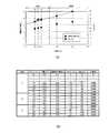
図6の(A)、(B)に、トリガスイッチ50の引量と速度指令電圧とデューティ比と回転数との特性を示し、図7にその一覧を示す。図6の(B)に示す回転数はモータ22の回転数であり、刈刃36の回転数ではない。ただし、モータ22の回転数が増加すれば刈刃36の回転数も増加するので、図6の(B)に示す回転数の数値とは異なるものの、刈刃36の回転数はモータ22の回転数と同じ特性を示す。 6A and 6B show characteristics of the pull amount, speed command voltage, duty ratio, and rotation speed of the
トリガスイッチ50が変位するときの上限位置は、前述したように引量切替スイッチ70により3段階に規制されている。1段目の上限位置が最も小さく、2段目、3段目の順に上限位置が大きくなる。すなわち、1段目におけるモータ22の最大回転数が最も小さく、2段目、3段目の順に最大回転数が大きくなる。 The upper limit position when the
また、図6に示すように、1段目においてトリガスイッチ50を引くことができる操作可能量が最も大きく、2段目、3段目の順に操作可能量が小さくなっている。
尚、トリガスイッチ50の各段の操作量とは、1段目はトリガスイッチ50の操作開始から最初の上限位置までの範囲の操作量を表し、2段目からは前段の上限位置、つまり該当段の下限位置から該当段の上限位置までの範囲の操作量を表す。Further, as shown in FIG. 6, the operable amount that can pull the
The operation amount of each stage of the
また、マイコン102において、3段の段毎にデューティ比が所定の設定数設定されており、各段の操作可能量に対するデューティ比の設定数の割合は、1段目が2段目および3段目よりも高くなっている。 Further, in the
マイコン102は、各段において、トリガスイッチ50から出力される速度指令電圧とデューティ比との対応関係を、前述した設定数分、マップとしてマイコン102内のROM等のメモリに記憶している。 At each stage, the
(回転数のヒステリシス特性)
使用者が引量切替スイッチ70を1段目に設定している状態でトリガスイッチ50を上限位置まで引くと、引量に応じてデューティ比が上昇し、モータ22の回転数、すなわち刈刃36の回転数は上昇する。使用者が1段目の上限位置にトリガスイッチ50を保持している場合には、刈刃36の回転数は1段目の最高回転数に保持される。(Hysteresis characteristics of rotational speed)
When the user pulls the
ここで、例えば使用者が長時間の作業により指が疲れ、トリガスイッチ50を上限位置に保持している力が弱まったためにトリガスイッチ50が上限位置から僅かに戻り引量が減少する場合、トリガスイッチ50から出力される速度指令電圧はトリガスイッチ50の引量が上限位置から減少すると低下する。 Here, for example, when the user is tired from long-term work and the force holding the
マイコン102は、トリガスイッチ50が上限位置に保持されている状態から僅かに戻ったことをトリガスイッチ50から出力される速度指令電圧に基づいて検出できる。
そして、マイコン102は、トリガスイッチ50が上限位置から僅かに戻った場合、トリガスイッチ50から出力される速度指令電圧に応じてデューティ比を低下するのではなく、デューティ比を上限位置と同じ値に設定し、ヒステリシス特性を持たせている。The
When the
図8では、引量が上限位置の4.5mmから4.4mmまで戻る間は上限位置と同じデューティ比に設定されている。これにより、引量が上限位置の4.5mmから4.4mmまで戻る間、刈刃36の回転数は上限位置と同じ最高回転数に保持される。 In FIG. 8, the same duty ratio as that of the upper limit position is set while the pulling amount returns from 4.5 mm as the upper limit position to 4.4 mm. Thereby, while the pulling amount returns from 4.5 mm at the upper limit position to 4.4 mm, the rotation speed of the
(逆回転制御)
次に、トリガスイッチ50の引量に応じた刈刃36に対する逆回転方向の回転数制御について説明する。(Reverse rotation control)
Next, the rotational speed control in the reverse rotation direction with respect to the
マイコン102は、回転方向切替スイッチ90が正回転方向または逆回転方向のいずれに設定されているかを、回転方向切替スイッチ90の出力信号から検出する。
そして、回転方向切替スイッチ90が逆回転方向に設定されている場合、マイコン102は、トリガスイッチ50の引量が1段目の範囲においては、図9に示すように、例えば正回転時と同じ特性に基づいてトリガスイッチ50の引量の増加に応じてモータ22の回転数を増加させる。この場合、正回転時と同様に、引量が上限位置の4.5mmからから4.4mmまで戻る間は上限位置と同じデューティ比に設定してもよい。The
When the rotation
一方、マイコン102は、トリガスイッチ50の出力である速度指令電圧からトリガスイッチ50が2段目または3段目において操作されていることを検出すると、図9に示すように、トリガスイッチ50の引量に関わらず2段目および3段目の回転数を1段目の最高回転数に保持する。 On the other hand, when the
(回転数制御ルーチン)
次に、上述の制御を実現するためにマイコン102が実行する処理を具体的に説明する。図10〜図12は、マイコン102がROM等のメモリに記憶されている制御プログラムを実行することにより処理するモータ22の回転数制御ルーチンである。図10〜図12において、「S」はステップを表している。(Rotational speed control routine)
Next, a process executed by the
(メインルーチン)
図10に、モータ22の回転数制御のメインルーチンを示す。図10のルーチンは常時実行される。(Main routine)
FIG. 10 shows a main routine for controlling the rotational speed of the
まず、メインルーチンにおいて、トリガスイッチ50が引かれているか否かを判定する(S400)。トリガスイッチ50が引かれている場合(S400:Yes)、トリガスイッチ50の引量とともに、回転方向切替スイッチ90により設定された回転方向に基づいてモータ22に対する通電量を制御するPWM信号のデューティ比を取得する(S402)。そして、取得したデューティ比に基づいてモータ22への通電を制御しモータ22を回転駆動する(S404)。 First, in the main routine, it is determined whether or not the
トリガスイッチ50が操作されず引かれていない場合(S400:No)、モータ22の回転を停止する(S406)。
(モータ制御値取得ルーチン)
図11および図12は、モータ22に対する制御値としてPWM信号のデューティ比を取得するルーチンである。When the
(Motor control value acquisition routine)
FIG. 11 and FIG. 12 are routines for obtaining the duty ratio of the PWM signal as a control value for the
図11において、トリガスイッチ50の引量が図7および図9に示すストロークNo.3より小さい場合(S410:Yes)、回転方向切替スイッチ90により正回転が設定されているか否かを判定する(S412)。 11, the
正回転が設定されている場合(S412:Yes)、PWM信号のデューティ比として正回転のデューティレベル1を設定し(S414)、本ルーチンを終了する。
逆回転が設定されている場合(S412:No)、PWM信号のデューティ比として逆回転のデューティレベル1を設定し(S416)、本ルーチンを終了する。When the forward rotation is set (S412: Yes), the
When the reverse rotation is set (S412: No), the reverse
図7および図9に示すように、本実施形態では、正回転および逆回転ともに、トリガスイッチ50の引量がストロークNo.3より小さい場合にはデューティ比として0%が設定される。つまり、トリガスイッチ50の引量がストロークNo.3より小さい場合には、モータ22は回転しない。 As shown in FIG. 7 and FIG. 9, in this embodiment, the pull amount of the
トリガスイッチ50の引量がストロークNo.3以上であり(S410:No)、No.4より小さい場合(S418:Yes)、回転方向切替スイッチ90により正回転が設定されているか否かを判定する(S420)。 The
正回転が設定されている場合(S420:Yes)、PWM信号のデューティ比として正回転のデューティレベル2を設定し(S422)、本ルーチンを終了する。
逆回転が設定されている場合(S420:No)、PWM信号のデューティ比として逆回転のデューティレベル2を設定し(S424)、本ルーチンを終了する。When the forward rotation is set (S420: Yes), the
When reverse rotation is set (S420: No), the reverse
図7および図9に示すように、本実施形態では、正回転および逆回転ともに、トリガスイッチ50の引量がストロークNo.3以上になると、デューティ比として0%より大きい値が設定される。つまり、トリガスイッチ50の引量がストロークNo.3以上になるとモータ22は回転する。 As shown in FIG. 7 and FIG. 9, in this embodiment, the pull amount of the
以下、S426〜S432において、トリガスイッチ50の引量と、回転方向切替スイッチ90により設定される回転方向とに基づいて、引量がストロークNo.13以下の場合に、PWM信号のデューティ比が設定される。 Hereinafter, in S426 to S432, the pulling amount is determined based on the pulling amount of the
次に、トリガスイッチ50の引量がNo.14以上であり(S426:No)、図12においてストロークNo.15より小さい場合(S434:Yes)、回転方向切替スイッチ90により正回転が設定されているか否かを判定する(S436)。 Next, when the
逆回転が設定されている場合(S436:No)、PWM信号のデューティ比として逆回転のデューティレベル13を設定し(S438)、本ルーチンを終了する。
正回転が設定されている場合(S436:Yes)、ヒステリシスフラグがセットされているか否かを判定する(S440)。If reverse rotation is set (S436: No), the reverse
When the normal rotation is set (S436: Yes), it is determined whether or not the hysteresis flag is set (S440).
ヒステリシスフラグは、トリガスイッチ50の引量が増加している場合はクリアされている。一方、図8に示すように、トリガスイッチ50が1段目の上限位置であるストロークNo.15に達し、ストロークNo.14’まで戻る間ではセットされている。 The hysteresis flag is cleared when the
ヒステリシスフラグがセットされていない場合(S440:No)、PWM信号のデューティ比として正回転のデューティレベル13を設定するとともにヒステリシスフラグをクリアし(S442)、本ルーチンを終了する。 When the hysteresis flag is not set (S440: No), the
ヒステリシスフラグがセットされている場合(S440:Yes)、トリガスイッチ50の引量がストロークNo.14’より小さいか否かを判定する(S444)。
トリガスイッチ50の引量がストロークNo.14’より小さい場合(S444:Yes)、トリガスイッチ50の引量がヒステリシス特性に基づいてデューティ比を設定する範囲から外れてストロークNo.14になったと判断し、PWM信号のデューティ比として正回転のデューティレベル13を設定し(S442)、本ルーチンを終了する。When the hysteresis flag is set (S440: Yes), the
The
ヒステリシスフラグがセットされており(S440:Yes)、トリガスイッチ50の引量がストロークNo.15より小さくストロークNo.14’以上の場合(S434:Yes、S444:No)、トリガスイッチ50の引量はヒステリシス特性に基づいてデューティ比を設定する範囲内で保持されているか減少していると判断する。この場合には、ヒステリシス特性に基づいて、PWM信号のデューティ比として、上限位置であるストロークNo.15と同じデューティレベル14を設定し(S446)、本ルーチンを終了する。 The hysteresis flag is set (S440: Yes), and the
次に、トリガスイッチ50の引量がストロークNo.16より小さいか否かを判定する(S448)。トリガスイッチ50の引量がストロークNo.16より小さい場合(S448:Yes)、回転方向切替スイッチ90により正回転が設定されているか否かを判定する(S450)。トリガスイッチ50の引量がストロークNo.16より小さい場合は(S448:Yes)、トリガスイッチ50は上限位置であるストロークNo.15に達している。 Next, the pull amount of the
そして、回転方向切替スイッチ90により正回転が設定されている場合(S450:Yes)、PWM信号のデューティ比として正回転のデューティレベル14を設定するとともにヒステリシスフラグをセットし(S452)、本ルーチンを終了する。 When the forward rotation is set by the rotation direction changeover switch 90 (S450: Yes), the forward
回転方向切替スイッチ90により逆回転が設定されている場合(S450:No)、PWM信号のデューティ比として逆回転のデューティレベル14を設定し(S454)、本ルーチンを終了する。 When reverse rotation is set by the rotation direction switch 90 (S450: No), the reverse
以下、S456〜S476において、回転方向切替スイッチ90により正回転が設定されている場合には、トリガスイッチ50の引量が増加すると正回転のデューティレベルを増加させ、モータ22の正回転の回転数を上昇させて本ルーチンを終了する。ただし、トリガスイッチ50の引量がストロークNo.22以上の場合には(S464:No)、ストロークNo.22と同じデューティレベル21が設定される。 Hereinafter, in S456 to S476, when the forward rotation is set by the rotation
一方、S456〜S476において、回転方向切替スイッチ90により逆回転が設定されている場合には、トリガスイッチ50の引量が1段目の上限値よりも大きくなっていると判断し、トリガスイッチ50の引量に関わらず、一定のデューティレベル14を設定して本ルーチンを終了する。これにより、逆回転が設定されると、モータ22の回転数は1段目の最高回転数に保持される。 On the other hand, if reverse rotation is set by the rotation
以上説明した上記実施形態では、トリガスイッチ50が変位するときの上限位置を、使用者が引量切替スイッチ70を操作して複数段のいずれかの上限位置に規制することにより、トリガスイッチ50を各上限位置に容易に保持できる。その結果、上限位置に対応する回転数にモータ回転数を容易に保持できる。したがって、モータ回転数を一定に保持した状態で長時間の作業を容易に実行できる。 In the above-described embodiment, when the
さらに、1段目において、トリガスイッチ50の操作可能量に対するデューティ比の設定数の割合を1段目以外の他段よりも高くしているので、1段目においてモータ22を低速で回転させる場合、トリガスイッチ50の操作量に対して細かくデューティ比を変化させることができる。これにより、モータ回転数を微調整して高い分解能でモータ回転数を制御できる。その結果、低速時における作業性が向上する。 Furthermore, in the first stage, the ratio of the set number of duty ratios to the operable amount of the
また、1段目におけるトリガスイッチの操作可能量は、他段におけるトリガスイッチ50の操作可能量よりも大きく設定されている。これにより、他段よりも操作量に対するデューティ比の設定数の割合が高い1段目において、選択できるモータ回転数の範囲が広がるので、低速側において広い回転数範囲で、高精度にモータ回転数を制御できる。その結果、低速回転時における作業性が向上する。 Further, the operable amount of the trigger switch in the first stage is set larger than the operable amount of the
また、トリガスイッチ50の1段目において、トリガスイッチ50が上限位置まで増加する場合にはモータ回転数が増加するようにデューティ比を制御するとともに、上限位置から所定位置であるストロークNo.14’に戻る場合には、ストロークNo.14’までモータ回転数がストロークNo.15と同じで一定になるヒステリシス特性によりデューティ比を制御している。 In the first stage of the
これにより、1段目において、トリガスイッチ50を指で上限位置に保持している状態で指が緩んでも、モータ回転数はストロークNo.14’まで変化しない。その結果、1段目において、トリガスイッチ50を上限位置に保持して長時間作業する場合に、モータ回転数を一定に保持しやすい。 As a result, in the first stage, even if the finger is loosened while the
また、回転方向切替スイッチ90により刈刃36の逆回転を選択できるとともに、逆回転の1段目において、トリガスイッチ50の引量の増加に応じてモータ回転数を増加させている。これにより、草刈機10の作業パターンが増加する。 In addition, reverse rotation of the
例えば、通常作業時に正回転により刈刃36にまとわりついた草を、モータ22を逆回転させることにより、使用者が草刈機10を保持しながら取り除くことができる。
本実施形態では、草刈機10が本発明の電動工具に相当し、刈刃36が本発明の工具に相当し、トリガスイッチ50が本発明の回転数調整スイッチに相当し、引量切替スイッチ70が本発明の規制部材に相当し、マイコン102が本発明の制御手段に相当する。For example, the grass clung to the
In this embodiment, the
また、トリガスイッチ50の引量が本発明の回転数調整スイッチの操作量に相当する。
また、図10から図12に示すS400からS476の処理が本発明の制御手段であるマイコン102が実行する機能に相当する。The pulling amount of the
Further, the processing from S400 to S476 shown in FIGS. 10 to 12 corresponds to the function executed by the
[他の実施形態]
上記実施形態では、トリガスイッチ50の引量を引量切替スイッチ70により3段に機械的に規制した。これに対し、トリガスイッチ50の引量は3段に限るものではなく、複数段に機械的に規制されればよい。[Other Embodiments]
In the above embodiment, the pulling amount of the
また、1段目以外の他段においても、トリガスイッチ50の引量が上限位置から所定位置まで減少する場合に、上限位置から所定位置までモータ回転数が一定になるヒステリシス特性によりデューティ比を制御してもよい。 In addition to the first stage, when the pulling amount of the
また、刈刃36の逆回転が設定される場合、1段目に限らず他段においても、トリガスイッチ50の引量の増加に応じてモータ22の回転数を増加させてもよい。
この場合、2段目においては、トリガスイッチ50の引量の増加に応じてモータ22の回転数を増加させ、3段目においては、トリガスイッチ50の引量に関わらずモータ22の回転数を2段目の最高回転数に保持してもよい。Further, when reverse rotation of the
In this case, in the second stage, the rotation speed of the
つまり、電動工具においてモータの逆回転が選択される場合、複数段のうち少なくとも1段目においては、操作量が増加するにしたがいモータの回転数を増加させるモータ制御を実行する。そして、それ以外の他段においては、前述したモータ制御を実行する段数のうちの最高段における最高回転数にモータの回転数を設定し、モータの回転数を一定に保持してもよい。 That is, when reverse rotation of the motor is selected in the electric tool, at least at the first stage among the plurality of stages, motor control is executed to increase the rotation speed of the motor as the operation amount increases. In other stages, the motor rotation speed may be set to the highest rotation speed at the highest stage among the stages performing the motor control described above, and the motor rotation speed may be kept constant.
また、1段目における操作可能量を他段よりも大きくする必要はなく、各段における操作可能量の大小をどのように設定してもよい。
上記実施形態では、正回転だけでなく逆回転を設定できる草刈機10について説明した。これに対し、正回転だけで逆回転を設定できない草刈機に本発明を適用してもよい。Further, it is not necessary to make the operable amount in the first stage larger than that in the other stages, and the size of the operable amount in each stage may be set in any way.
In the above embodiment, the
また、上記実施形態では、本発明を草刈機に適用した例を示したが、これはあくまでも一例であって、モータを駆動源として動作するあらゆる電動工具、例えばヘッジトリマ、ドライバに適用することができる。 Moreover, although the example which applied this invention to the mower was shown in the said embodiment, this is an example to the last, Comprising: It can apply to all the electric tools which operate | move using a motor as a drive source, for example, a hedge trimmer, a driver. .
上記実施形態に対し、トリガスイッチ50の上限位置を複数段に機械的に規制しない草刈機において、トリガスイッチ50の引量が上限位置から所定位置まで減少する場合に、上限位置から所定位置までモータ回転数が一定になるヒステリシス特性によりデューティ比を制御してもよい。 In the mower that does not mechanically restrict the upper limit position of the
あるいは、トリガスイッチ50の上限位置を複数段に機械的に規制するが、1段目において、トリガスイッチ50の操作可能量に対するデューティ比の設定数の割合を1段目以外の他段よりも高くしていない草刈機において、1段目におけるトリガスイッチ50の引量が上限位置から所定位置まで減少する場合に、上限位置から所定位置までモータ回転数が一定になるヒステリシス特性によりデューティ比を制御してもよい。 Alternatively, the upper limit position of the
また、電動工具のモータの駆動方法は、本実施形態のようにスイッチ自体でモータに流れる電流の向きを逆にして回転方向を切り替える方法であってもよいし、Hブリッジ回路を使用してもよいし、ブラシレスモータを駆動するインバータ回路を使用してもよい。 Further, the driving method of the motor of the electric tool may be a method of switching the rotation direction by reversing the direction of the current flowing in the motor with the switch itself as in this embodiment, or using an H-bridge circuit. Alternatively, an inverter circuit that drives a brushless motor may be used.
上記実施形態では、本発明の制御手段の機能を制御プログラムにより機能が特定されるマイコン102により実現している。これに対し、制御段の機能の少なくとも一部を、回路構成自体で機能が特定されるハードウェアで実現してもよい。 In the above embodiment, the function of the control means of the present invention is realized by the
このように、本発明は、上記実施形態に限定されるものではなく、その要旨を逸脱しない範囲で種々の実施形態に適用可能である。 As described above, the present invention is not limited to the above-described embodiment, and can be applied to various embodiments without departing from the gist thereof.
10:草刈機(電動工具)、22:モータ、36:刈刃(工具)、50:トリガスイッチ(回転数調整スイッチ)、70:引量切替スイッチ(規制部材)、90:回転方向切替スイッチ、102:マイコン(制御手段)10: Mower (electric tool), 22: Motor, 36: Cutting blade (tool), 50: Trigger switch (rotational speed adjustment switch), 70: Pull switch (regulating member), 90: Rotation direction switch, 102: Microcomputer (control means)
Claims (3)
Translated fromJapanese使用者の操作により変位する回転数調整スイッチと、
前記回転数調整スイッチが変位するときの上限位置を前記使用者の操作により複数段のいずれかの上限位置に規制する規制部材と、
前記回転数調整スイッチの操作量に基づいて前記モータに対する通電量をデューティ比により制御し、前記操作量の増加に応じて前記モータの回転数を増加させ、前記複数段の段毎に前記デューティ比を所定の設定数設定しており、前記上限位置が1番小さい1段目において、前記回転数調整スイッチの操作可能量に対する前記デューティ比の前記設定数の割合を前記1段目以外の他段よりも高くし、前記回転数調整スイッチの操作可能量に対する前記1段目における前記デューティ比の変化量を、前記回転数調整スイッチの操作可能量に対する前記1段目以外の前記他段における前記デューティ比の変化量よりも小さく設定する制御手段と、
を備え、
前記制御手段は、前記複数段のうち少なくとも前記1段目において、前記回転数調整スイッチの操作量が前記上限位置まで増加する場合には前記回転数が増加するように前記デューティ比を制御するとともに、前記上限位置から所定位置まで減少する場合には、前記所定位置まで前記回転数が一定になるヒステリシス特性により前記デューティ比を制御する
ことを特徴とする電動工具。A motor for driving the tool;
A rotation speed adjustment switch that is displaced by a user's operation;
A regulating member that regulates the upper limit position when the rotation speed adjustment switch is displaced to any one of the upper limit positions of the plurality of stages by the operation of the user;
Based on the operation amount of the rotation speed adjustment switch, the energization amount to the motor is controlled by a duty ratio, the rotation speed of the motor is increased according to the increase of the operation amount, and the duty ratio is increased for each of the plurality of stages. Is set to a predetermined number, and in the first stage where the upper limit position is the smallest, the ratio of the set number of the duty ratio to the operable amount of the rotation speed adjustment switch is set to a stage other than the first stage. Theduty ratio change amount at the first stage with respect to the operable amount of the rotation speed adjustment switch is set to a duty ratio at the other stage other than the first stage with respect to the operable amount of the rotation speed adjustment switch. Control means forsetting smaller than the amount of change in the ratio ;
Equipped witha,
The control means controls the duty ratio so that the rotation speed increases when the operation amount of the rotation speed adjustment switch increases to the upper limit position in at least the first stage of the plurality of stages. The electric power tool accordingto claim 1, wherein the duty ratio is controlled by a hysteresis characteristic in which the rotational speed is constant until the predetermined position when the upper limit position decreases to the predetermined position .
前記規制部材は、前記1段目における前記操作可能量が前記他段における前記操作可能量よりも大きくなるように前記上限位置を規制する
ことを特徴とする電動工具。The electric tool according to claim 1,
The electric power tool characterized in that the restricting member restricts the upper limit position so that the operable amount in the first stage is larger than the operable amount in the other stage.
使用者の操作により前記モータの回転を正回転または逆回転のいずれかに切り替える回転方向切替スイッチを備え、
前記制御手段は、前記回転方向切替スイッチにより前記モータの逆回転が選択されると、少なくとも前記1段目において前記操作量が増加するにしたがい前記回転数を増加させるとともに、それ以外の他段において前記操作量に関わらず前記回転数を一定にする
ことを特徴とする電動工具。The electric tool according toclaim 1or 2 ,
A rotation direction changeover switch that switches the rotation of the motor to either forward rotation or reverse rotation by a user operation,
When the reverse rotation of the motor is selected by the rotation direction changeover switch, the control means increases the rotational speed as the operation amount increases at least in the first stage, and in other stages. An electric tool characterized in that the rotational speed is made constant regardless of the operation amount.
Priority Applications (6)
| Application Number | Priority Date | Filing Date | Title |
|---|---|---|---|
| JP2009258056AJP5394895B2 (en) | 2009-11-11 | 2009-11-11 | Electric tool |
| EP10829855.5AEP2500144A4 (en) | 2009-11-11 | 2010-10-29 | Power tool |
| US13/509,436US9314914B2 (en) | 2009-11-11 | 2010-10-29 | Power tool |
| PCT/JP2010/069368WO2011058895A1 (en) | 2009-11-11 | 2010-10-29 | Power tool |
| CN201080051008.0ACN102596514B (en) | 2009-11-11 | 2010-10-29 | electrical tools |
| RU2012124036/02ARU2540238C2 (en) | 2009-11-11 | 2010-10-29 | Drive tool |
Applications Claiming Priority (1)
| Application Number | Priority Date | Filing Date | Title |
|---|---|---|---|
| JP2009258056AJP5394895B2 (en) | 2009-11-11 | 2009-11-11 | Electric tool |
Publications (2)
| Publication Number | Publication Date |
|---|---|
| JP2011101932A JP2011101932A (en) | 2011-05-26 |
| JP5394895B2true JP5394895B2 (en) | 2014-01-22 |
Family
ID=43991554
Family Applications (1)
| Application Number | Title | Priority Date | Filing Date |
|---|---|---|---|
| JP2009258056AExpired - Fee RelatedJP5394895B2 (en) | 2009-11-11 | 2009-11-11 | Electric tool |
Country Status (6)
| Country | Link |
|---|---|
| US (1) | US9314914B2 (en) |
| EP (1) | EP2500144A4 (en) |
| JP (1) | JP5394895B2 (en) |
| CN (1) | CN102596514B (en) |
| RU (1) | RU2540238C2 (en) |
| WO (1) | WO2011058895A1 (en) |
Families Citing this family (31)
| Publication number | Priority date | Publication date | Assignee | Title |
|---|---|---|---|---|
| JP5668290B2 (en)* | 2010-01-14 | 2015-02-12 | 日立工機株式会社 | Electric working machine |
| JP5829006B2 (en) | 2010-01-14 | 2015-12-09 | 日立工機株式会社 | Electric working machine |
| JP5381871B2 (en) | 2010-03-31 | 2014-01-08 | 日立工機株式会社 | Two-cycle engine and engine working machine equipped with the same |
| WO2012167241A1 (en)* | 2011-06-02 | 2012-12-06 | Black & Decker Inc. | Control system for a fastening power tool |
| US8572940B2 (en)* | 2012-02-09 | 2013-11-05 | The Toro Company | Mower with thumb wheel throttle control |
| JP2014069252A (en)* | 2012-09-28 | 2014-04-21 | Hitachi Koki Co Ltd | Power tool |
| JP2014091167A (en)* | 2012-10-31 | 2014-05-19 | Hitachi Koki Co Ltd | Electric power tool |
| JP6085469B2 (en)* | 2012-12-19 | 2017-02-22 | 株式会社マキタ | Electric mower |
| JP6283161B2 (en)* | 2012-12-19 | 2018-02-21 | 株式会社マキタ | Work machine with operation rod |
| JP6086001B2 (en)* | 2013-03-13 | 2017-03-01 | 株式会社島津製作所 | Vacuum pump |
| WO2015061370A1 (en) | 2013-10-21 | 2015-04-30 | Milwaukee Electric Tool Corporation | Adapter for power tool devices |
| EP2875909B1 (en)* | 2013-11-21 | 2020-11-04 | Robert Bosch GmbH | Supporting device for at least one electrical unit of electrically driveable tools |
| EP2875904B1 (en)* | 2013-11-21 | 2016-10-05 | Robert Bosch Gmbh | Switching device for electrically driveable garden tools |
| CN104617853A (en)* | 2014-10-28 | 2015-05-13 | 常州格力博有限公司 | Pruning machine speed regulation control method |
| JP6457798B2 (en)* | 2014-11-26 | 2019-01-23 | 株式会社マキタ | Electric equipment |
| JP6357116B2 (en)* | 2015-01-23 | 2018-07-11 | 株式会社マキタ | Brush cutter |
| US10491148B2 (en)* | 2015-11-06 | 2019-11-26 | Makita Corporation | Electric working machine |
| JP6845655B2 (en) | 2016-10-04 | 2021-03-24 | 株式会社マキタ | Electric work machine |
| JP6906165B2 (en)* | 2017-01-13 | 2021-07-21 | パナソニックIpマネジメント株式会社 | Electric tool |
| JP6590262B2 (en)* | 2017-01-13 | 2019-10-16 | パナソニックIpマネジメント株式会社 | Electric tool |
| USD828125S1 (en)* | 2017-01-31 | 2018-09-11 | The Toro Company | Handle for lawn and garden tool |
| USD832669S1 (en) | 2017-04-25 | 2018-11-06 | The Toro Company | Handle for lawn and garden tool |
| JP2019134693A (en)* | 2018-02-05 | 2019-08-15 | 株式会社マキタ | Hedge trimmer |
| CN110417331B (en)* | 2018-04-28 | 2021-11-19 | 南京德朔实业有限公司 | Electric tool |
| JP7531171B2 (en)* | 2019-04-09 | 2024-08-09 | パナソニックIpマネジメント株式会社 | Power tools |
| CN112140066B (en)* | 2019-06-11 | 2024-04-09 | 苏州宝时得电动工具有限公司 | Electric tool |
| CN110336516A (en)* | 2019-06-26 | 2019-10-15 | 江苏苏美达五金工具有限公司 | The constant speed cruising method of motor, system and circuit in electric garden tool |
| EP3815509B1 (en)* | 2019-10-29 | 2024-04-17 | Andreas Stihl AG & Co. KG | Manually guided garden, forestry and / or construction machinery and method for a manually guided garden, forestry and / or construction machinery |
| USD960670S1 (en) | 2019-12-27 | 2022-08-16 | The Toro Company | Handle for lawn and garden tool |
| US11858103B1 (en)* | 2020-08-20 | 2024-01-02 | Dylan Myers | Clamping grip for hydraulic tamper |
| US20230188064A1 (en)* | 2021-12-15 | 2023-06-15 | Milwaukee Electric Tool Corporation | Adaptive trigger mapping |
Family Cites Families (36)
| Publication number | Priority date | Publication date | Assignee | Title |
|---|---|---|---|---|
| US3548136A (en) | 1968-05-29 | 1970-12-15 | Skil Corp | Trigger actuated switch device with adjustment means for establishing a plurality of predetermined trigger positions |
| US3632936A (en)* | 1970-10-28 | 1972-01-04 | Cutler Hammer Inc | Integral reversing trigger switches for speed controlled portable tools |
| US4734629A (en) | 1985-08-09 | 1988-03-29 | Black & Decker Inc. | Variable speed trigger switch |
| JPH0163027U (en)* | 1987-10-19 | 1989-04-24 | ||
| US5206028A (en)* | 1991-02-11 | 1993-04-27 | Li Shu Tung | Dense collagen membrane matrices for medical uses |
| JP3086991B2 (en) | 1993-03-04 | 2000-09-11 | 株式会社マキタ | Power tool switch mechanism |
| JPH0719838A (en) | 1993-07-05 | 1995-01-20 | Daido Steel Co Ltd | Appearance inspection method and device |
| JP2730487B2 (en) | 1994-05-31 | 1998-03-25 | オムロン株式会社 | Trigger switch |
| DE19508925A1 (en)* | 1995-03-13 | 1996-09-19 | Marquardt Gmbh | Electrical switch, in particular for electrical hand tools |
| RU2131154C1 (en)* | 1997-01-06 | 1999-05-27 | Государственное предприятие "Ижевский механический завод" | Electrical machine control unit |
| JP3301533B2 (en) | 1997-03-04 | 2002-07-15 | 株式会社マキタ | Motor control circuit |
| US6536536B1 (en)* | 1999-04-29 | 2003-03-25 | Stephen F. Gass | Power tools |
| JP3768400B2 (en)* | 2000-11-17 | 2006-04-19 | 佐鳥エス・テック株式会社 | Electric tool switch |
| US6696814B2 (en) | 2001-07-09 | 2004-02-24 | Tyco Electronics Corporation | Microprocessor for controlling the speed and frequency of a motor shaft in a power tool |
| GB0226523D0 (en)* | 2002-11-14 | 2002-12-18 | Black & Decker Inc | Electric motor driven hand-held tool |
| NL1025144C2 (en)* | 2003-12-30 | 2005-07-04 | Bosch Gmbh Robert | Power tool with double-control switch. |
| JP4019054B2 (en)* | 2004-02-09 | 2007-12-05 | リョービ株式会社 | Electric tool |
| CN101897989B (en)* | 2004-02-23 | 2013-11-13 | 洛马林达大学医学中心 | Hemostatic agent for topical and internal use |
| US6971454B2 (en)* | 2004-03-16 | 2005-12-06 | Bogue Edward M | Pulsed rotation screw removal and insertion device |
| US7331406B2 (en)* | 2004-06-21 | 2008-02-19 | Duraspin Products Llc | Apparatus for controlling a fastener driving tool, with user-adjustable torque limiting control |
| US20060185870A1 (en)* | 2005-02-18 | 2006-08-24 | Black & Decker Inc. | Drill chuck |
| GB0503784D0 (en)* | 2005-02-24 | 2005-03-30 | Black & Decker Inc | Hammer drill |
| JP4440169B2 (en)* | 2005-05-16 | 2010-03-24 | 株式会社マキタ | Electric impact tool |
| CN101300732B (en)* | 2005-11-04 | 2011-02-23 | 罗伯特·博世有限公司 | Drill with solid state speed control and method of operating |
| US8657030B2 (en)* | 2006-03-03 | 2014-02-25 | Black & Decker Inc. | Cordless power tool having multi-speed transmission and constant speed in light torque range |
| US7821217B2 (en) | 2006-05-22 | 2010-10-26 | Black & Decker Inc. | Electronically commutated motor and control system employing phase angle control of phase current |
| JP2008296323A (en)* | 2007-05-31 | 2008-12-11 | Hitachi Koki Co Ltd | Electric tool |
| JP5360344B2 (en) | 2007-09-21 | 2013-12-04 | 日立工機株式会社 | Electric tool |
| JP5376392B2 (en) | 2008-02-14 | 2013-12-25 | 日立工機株式会社 | Electric tool |
| US8091756B2 (en)* | 2008-05-09 | 2012-01-10 | Tyco Healthcare Group Lp | Varying tissue compression using take-up component |
| CN101676052B (en)* | 2008-09-19 | 2013-10-30 | 德昌电机(深圳)有限公司 | Electric drill with force sensing device |
| JP2010155291A (en)* | 2008-12-26 | 2010-07-15 | Makita Corp | Power tool |
| US8653764B2 (en)* | 2009-08-18 | 2014-02-18 | Robert Bosch Gmbh | Electronic orbit control for saws |
| JP5256151B2 (en) | 2009-09-02 | 2013-08-07 | 株式会社マキタ | Brush cutter |
| US8418778B2 (en)* | 2010-01-07 | 2013-04-16 | Black & Decker Inc. | Power screwdriver having rotary input control |
| EP2434634B1 (en)* | 2010-09-28 | 2024-08-21 | Black & Decker Inc. | Method and system for prevention of motor reversal |
- 2009
- 2009-11-11JPJP2009258056Apatent/JP5394895B2/ennot_activeExpired - Fee Related
- 2010
- 2010-10-29CNCN201080051008.0Apatent/CN102596514B/ennot_activeExpired - Fee Related
- 2010-10-29EPEP10829855.5Apatent/EP2500144A4/ennot_activeWithdrawn
- 2010-10-29RURU2012124036/02Apatent/RU2540238C2/ennot_activeIP Right Cessation
- 2010-10-29WOPCT/JP2010/069368patent/WO2011058895A1/enactiveApplication Filing
- 2010-10-29USUS13/509,436patent/US9314914B2/ennot_activeExpired - Fee Related
Also Published As
| Publication number | Publication date |
|---|---|
| US20120234573A1 (en) | 2012-09-20 |
| JP2011101932A (en) | 2011-05-26 |
| US9314914B2 (en) | 2016-04-19 |
| WO2011058895A1 (en) | 2011-05-19 |
| EP2500144A1 (en) | 2012-09-19 |
| RU2540238C2 (en) | 2015-02-10 |
| CN102596514B (en) | 2015-05-13 |
| EP2500144A4 (en) | 2015-10-14 |
| CN102596514A (en) | 2012-07-18 |
| RU2012124036A (en) | 2013-12-20 |
Similar Documents
| Publication | Publication Date | Title |
|---|---|---|
| JP5394895B2 (en) | Electric tool | |
| US11701759B2 (en) | Electric power tool | |
| CN105473287B (en) | Electric tool | |
| JP5491346B2 (en) | Power tools and programs | |
| CN106998168B (en) | Electric working machine | |
| JP4929009B2 (en) | Electric brush cutter | |
| US10491148B2 (en) | Electric working machine | |
| US11533841B2 (en) | Electric working machine and method for controlling motor of electric working machine | |
| JP6845655B2 (en) | Electric work machine | |
| JP7095688B2 (en) | Electric tool | |
| JP2022159375A (en) | Motor-driven working machine | |
| JP7086624B2 (en) | Electric tool | |
| JP6092005B2 (en) | Mower | |
| CN112171591B (en) | Handheld machine tool with electronically commutated motor | |
| JP7281917B2 (en) | electric work machine | |
| JP2022180078A (en) | electric work machine | |
| US9312795B2 (en) | Electric power tool | |
| JP2020104244A (en) | Electric work machine | |
| CN106541372A (en) | Electric tool and its method using travel switch controlled motor rotating speed | |
| JP4563259B2 (en) | Electric tool | |
| AU2023296082A1 (en) | Work machine | |
| US7395875B2 (en) | Rechargeable battery-operated hand machine tool | |
| JP2007051621A (en) | Engine-driven work equipment | |
| JP2023071389A (en) | Electrically-driven work machine | |
| JP7586481B2 (en) | Electric grass cutter |
Legal Events
| Date | Code | Title | Description |
|---|---|---|---|
| A621 | Written request for application examination | Free format text:JAPANESE INTERMEDIATE CODE: A621 Effective date:20120625 | |
| A131 | Notification of reasons for refusal | Free format text:JAPANESE INTERMEDIATE CODE: A131 Effective date:20130730 | |
| A521 | Written amendment | Free format text:JAPANESE INTERMEDIATE CODE: A523 Effective date:20130905 | |
| TRDD | Decision of grant or rejection written | ||
| A01 | Written decision to grant a patent or to grant a registration (utility model) | Free format text:JAPANESE INTERMEDIATE CODE: A01 Effective date:20130924 | |
| A61 | First payment of annual fees (during grant procedure) | Free format text:JAPANESE INTERMEDIATE CODE: A61 Effective date:20131017 | |
| R150 | Certificate of patent or registration of utility model | Free format text:JAPANESE INTERMEDIATE CODE: R150 | |
| R250 | Receipt of annual fees | Free format text:JAPANESE INTERMEDIATE CODE: R250 | |
| LAPS | Cancellation because of no payment of annual fees |