JP5394360B2 - Vertical heat treatment apparatus and cooling method thereof - Google Patents
Vertical heat treatment apparatus and cooling method thereofDownload PDFInfo
- Publication number
- JP5394360B2 JP5394360B2JP2010281622AJP2010281622AJP5394360B2JP 5394360 B2JP5394360 B2JP 5394360B2JP 2010281622 AJP2010281622 AJP 2010281622AJP 2010281622 AJP2010281622 AJP 2010281622AJP 5394360 B2JP5394360 B2JP 5394360B2
- Authority
- JP
- Japan
- Prior art keywords
- air
- space
- furnace body
- air supply
- pressure
- Prior art date
- Legal status (The legal status is an assumption and is not a legal conclusion. Google has not performed a legal analysis and makes no representation as to the accuracy of the status listed.)
- Active
Links
Images


Classifications
- H—ELECTRICITY
- H01—ELECTRIC ELEMENTS
- H01L—SEMICONDUCTOR DEVICES NOT COVERED BY CLASS H10
- H01L21/00—Processes or apparatus adapted for the manufacture or treatment of semiconductor or solid state devices or of parts thereof
- H01L21/67—Apparatus specially adapted for handling semiconductor or electric solid state devices during manufacture or treatment thereof; Apparatus specially adapted for handling wafers during manufacture or treatment of semiconductor or electric solid state devices or components ; Apparatus not specifically provided for elsewhere
- H01L21/67005—Apparatus not specifically provided for elsewhere
- H01L21/67242—Apparatus for monitoring, sorting or marking
- H01L21/67253—Process monitoring, e.g. flow or thickness monitoring
- C—CHEMISTRY; METALLURGY
- C23—COATING METALLIC MATERIAL; COATING MATERIAL WITH METALLIC MATERIAL; CHEMICAL SURFACE TREATMENT; DIFFUSION TREATMENT OF METALLIC MATERIAL; COATING BY VACUUM EVAPORATION, BY SPUTTERING, BY ION IMPLANTATION OR BY CHEMICAL VAPOUR DEPOSITION, IN GENERAL; INHIBITING CORROSION OF METALLIC MATERIAL OR INCRUSTATION IN GENERAL
- C23C—COATING METALLIC MATERIAL; COATING MATERIAL WITH METALLIC MATERIAL; SURFACE TREATMENT OF METALLIC MATERIAL BY DIFFUSION INTO THE SURFACE, BY CHEMICAL CONVERSION OR SUBSTITUTION; COATING BY VACUUM EVAPORATION, BY SPUTTERING, BY ION IMPLANTATION OR BY CHEMICAL VAPOUR DEPOSITION, IN GENERAL
- C23C16/00—Chemical coating by decomposition of gaseous compounds, without leaving reaction products of surface material in the coating, i.e. chemical vapour deposition [CVD] processes
- C23C16/44—Chemical coating by decomposition of gaseous compounds, without leaving reaction products of surface material in the coating, i.e. chemical vapour deposition [CVD] processes characterised by the method of coating
- C23C16/46—Chemical coating by decomposition of gaseous compounds, without leaving reaction products of surface material in the coating, i.e. chemical vapour deposition [CVD] processes characterised by the method of coating characterised by the method used for heating the substrate
- C23C16/463—Cooling of the substrate
- H—ELECTRICITY
- H01—ELECTRIC ELEMENTS
- H01L—SEMICONDUCTOR DEVICES NOT COVERED BY CLASS H10
- H01L21/00—Processes or apparatus adapted for the manufacture or treatment of semiconductor or solid state devices or of parts thereof
- H01L21/67—Apparatus specially adapted for handling semiconductor or electric solid state devices during manufacture or treatment thereof; Apparatus specially adapted for handling wafers during manufacture or treatment of semiconductor or electric solid state devices or components ; Apparatus not specifically provided for elsewhere
- H01L21/67005—Apparatus not specifically provided for elsewhere
- H01L21/67011—Apparatus for manufacture or treatment
- H01L21/67098—Apparatus for thermal treatment
- H01L21/67109—Apparatus for thermal treatment mainly by convection
Landscapes
- Engineering & Computer Science (AREA)
- Chemical & Material Sciences (AREA)
- Manufacturing & Machinery (AREA)
- General Physics & Mathematics (AREA)
- Physics & Mathematics (AREA)
- Computer Hardware Design (AREA)
- Microelectronics & Electronic Packaging (AREA)
- Power Engineering (AREA)
- Condensed Matter Physics & Semiconductors (AREA)
- General Chemical & Material Sciences (AREA)
- Chemical Kinetics & Catalysis (AREA)
- Materials Engineering (AREA)
- Mechanical Engineering (AREA)
- Metallurgy (AREA)
- Organic Chemistry (AREA)
- Furnace Details (AREA)
- Chemical Vapour Deposition (AREA)
- Heat Treatment Of Articles (AREA)
Description
Translated fromJapanese本発明は、縦型熱処理装置およびその冷却方法に係り、とりわけ炉本体と処理容器との間の空間を精度良く冷却することができる縦型熱処理装置およびその冷却方法に関する。 The present invention relates to a vertical heat treatment apparatus and a cooling method therefor, and more particularly to a vertical heat treatment apparatus and a cooling method therefor that can accurately cool a space between a furnace body and a processing vessel.
半導体装置の製造においては、被処理体である半導体ウエハに酸化、拡散、CVD(Chemical Vapor Deposition)などの処理を施すために、各種の縦型熱処理装置が用いられている。そして、その一般的な縦型熱処理装置は、半導体ウエハを収容して熱処理するための処理容器と、この処理容器の周囲を覆うように設けられ処理容器内のウエハを加熱する炉本体とを含む熱処理炉を備えている。上記炉本体は、円筒状の断熱材と、この断熱材の内周面に支持体を介して設けられた発熱抵抗体とを有する。 In the manufacture of semiconductor devices, various vertical heat treatment apparatuses are used in order to perform processes such as oxidation, diffusion, and CVD (Chemical Vapor Deposition) on a semiconductor wafer that is a target object. The general vertical heat treatment apparatus includes a processing container for housing and heat-treating a semiconductor wafer, and a furnace body that is provided so as to cover the periphery of the processing container and heats the wafer in the processing container. A heat treatment furnace is provided. The furnace body has a cylindrical heat insulating material and a heating resistor provided on the inner peripheral surface of the heat insulating material via a support.
上記発熱抵抗体としては、例えばバッチ処理が可能な熱処理装置の場合でいうと、円筒状の断熱材の内壁面に沿って配置される螺旋状のヒータエレメント(ヒータ線、発熱抵抗体ともいう)が用いられ、炉内を例えば500〜1000℃程度に高温に加熱することができる。また、上記断熱材としては、例えばセラミックファイバ等からなる断熱材料を円筒状に焼成してなるものが用いられ、輻射熱および伝導熱として奪われる熱量を減少させて効率のよい加熱を助長することができる。上記支持体としては、例えばセラミック製のものが用いられ、上記ヒータエレメントを熱膨張および熱収縮可能に所定のピッチで支持するようになっている。 As the heat generating resistor, for example, in the case of a heat treatment apparatus capable of batch processing, a spiral heater element (also referred to as a heater wire or a heat generating resistor) disposed along the inner wall surface of a cylindrical heat insulating material. Can be used, and the inside of the furnace can be heated to a high temperature of, for example, about 500 to 1000 ° C. In addition, as the heat insulating material, for example, a heat insulating material made of a ceramic fiber or the like is fired into a cylindrical shape, and the amount of heat taken as radiant heat and conduction heat is reduced to promote efficient heating. it can. As the support, for example, ceramic is used, and the heater element is supported at a predetermined pitch so as to be capable of thermal expansion and contraction.
ところで、上述した縦型熱処理装置においては、ウエハを高温で加熱した後、炉本体と処理容器との間の空間を急速に冷却し、ウエハに対する熱処理の精度を維持しながら熱処理作業の効率化を図る方法が開発されている。 By the way, in the vertical heat treatment apparatus described above, after the wafer is heated at a high temperature, the space between the furnace body and the processing vessel is rapidly cooled to improve the efficiency of the heat treatment work while maintaining the accuracy of the heat treatment for the wafer. A method has been developed.
このように縦型熱処理装置に対して急速冷却方法を実行する場合、炉本体と処理容器との間の空間内の圧力が陽圧になると、炉本体から外部へ熱風が噴出し、炉本体自体および炉本体の周縁機器が破損することも考えられる。他方、この空間内の圧力が強陰圧になると、炉本体の断熱材の破損が生じたり、炉本体内へ外気を巻き込み処理容器内において温度の分布が不均一となり、局部的に発熱抵抗体が破損することも考えられる。 When the rapid cooling method is performed on the vertical heat treatment apparatus in this way, when the pressure in the space between the furnace body and the processing vessel becomes positive, hot air is ejected from the furnace body to the outside, and the furnace body itself It is also possible that the peripheral equipment of the furnace body is damaged. On the other hand, if the pressure in this space becomes a strong negative pressure, the heat insulation material of the furnace body will be damaged, or outside air will be engulfed in the furnace body and the temperature distribution will be non-uniform in the processing vessel, and the heating resistor will be locally May be damaged.
そこで縦型熱処理装置に対して急速冷却方法を実行する場合、炉本体と処理容器との間の空間内の圧力を微陰圧に保つことが必要となっている。しかしながら従来よりこの炉本体と処理容器との間の空間内の圧力を精度良くかつ確実に微陰圧に保つ方法は未だ開発されていないのが実情である。 Therefore, when the rapid cooling method is performed on the vertical heat treatment apparatus, it is necessary to maintain the pressure in the space between the furnace body and the processing vessel at a slight negative pressure. However, in reality, no method has been developed so far to maintain the pressure in the space between the furnace body and the processing vessel accurately and reliably at a slightly negative pressure.
本発明はこのような点を考慮してなされたものであり、炉本体と処理容器との間の空間内の圧力を微陰圧に精度良く調整して急速冷却を行うことができる縦型熱処理装置およびその冷却方法を提供することを目的とする。 The present invention has been made in consideration of such points, and vertical heat treatment that can perform rapid cooling by accurately adjusting the pressure in the space between the furnace body and the processing vessel to a slight negative pressure. An object is to provide an apparatus and a cooling method thereof.
本発明は、内周面に加熱部が設けられた炉本体と、炉本体内に配置され、炉本体との間に空間を形成するとともに、内部に複数の被処理体を収納する処理容器と、炉本体に設けられた複数の空気吹出し孔と、炉本体に接続され、複数の空気吹出し孔を介して空間内に冷却用空気を供給する空気供給ラインと、炉本体に接続され、空間内から冷却用空気を排気する空気排気ラインと、空気供給ラインおよび空気排気ラインの少なくとも一方に設けられたブロアと、空気供給ラインおよび空気排気ラインに各々設けられた空気供給ライン側弁機構および空気排気ライン側弁機構と、炉本体と処理容器との間の空間内の圧力を検知する圧力検知システムと、圧力検知システムからの検知信号に基づいて、ブロア、空気供給ライン側弁機構および空気排気ライン側弁機構のうち少なくとも一方を制御して空間内の圧力を微陰圧とする制御部とを備え、圧力検知システムは、炉本体と処理容器との間の空間のうち、空気吹出し孔の設置領域に対応する空間領域に設けられていることを特徴とする縦型熱処理装置である。 The present invention relates to a furnace main body provided with a heating unit on the inner peripheral surface, a processing container disposed in the furnace main body, forming a space between the furnace main body, and storing a plurality of objects to be processed therein. A plurality of air blowing holes provided in the furnace body, an air supply line connected to the furnace body and supplying cooling air into the space through the plurality of air blowing holes, and connected to the furnace body. An air exhaust line for exhausting cooling air from the air, a blower provided in at least one of the air supply line and the air exhaust line, an air supply line side valve mechanism provided in each of the air supply line and the air exhaust line, and air exhaust A line-side valve mechanism, a pressure detection system for detecting the pressure in the space between the furnace body and the processing vessel, and a blower, an air supply line-side valve mechanism and air based on a detection signal from the pressure detection system A control unit that controls at least one of the gas line side valve mechanisms to make the pressure in the space a slight negative pressure, and the pressure detection system includes an air blowing hole in the space between the furnace body and the processing vessel. The vertical heat treatment apparatus is provided in a space region corresponding to the installation region.
本発明は、制御部は空間内を0Pa〜−85Paの微陰圧とすることを特徴とする縦型熱処理装置である。 The present invention is the vertical heat treatment apparatus characterized in that the control unit sets a slight negative pressure of 0 Pa to -85 Pa in the space.
本発明は、制御部は空間内を−20Pa〜−30Paの微陰圧とすることを特徴とする縦型熱処理装置である。 The present invention is the vertical heat treatment apparatus characterized in that the control unit sets a slight negative pressure of −20 Pa to −30 Pa in the space.
本発明は、空気供給ラインと空気排気ラインは互いに連結されてクローズ系空気供給/排気ラインを構成し、当該クローズ系空気ラインに、空気供給および空気排気用のブロアが設けられていることを特徴とする縦型熱処理装置である。 In the present invention, the air supply line and the air exhaust line are connected to each other to form a closed system air supply / exhaust line, and the closed system air line is provided with a blower for air supply and air exhaust. Is a vertical heat treatment apparatus.
本発明は、空気供給ラインと空気排気ラインは各々独立して設けられてオープン系空気供給/排気ラインを構成し、空気供給ラインに空気供給ブロアが設けられ、空気排気ラインに空気排気ブロアが設けられていることを特徴とする縦型熱処理装置である。 In the present invention, the air supply line and the air exhaust line are provided independently to constitute an open air supply / exhaust line, the air supply line is provided with the air supply blower, and the air exhaust line is provided with the air exhaust blower. This is a vertical heat treatment apparatus.
本発明は、制御部は圧力検知システムからの検知信号に基づいて、ブロアの回転数を制御して空間内を微陰圧とすることを特徴とする縦型熱処理装置である。 The present invention is the vertical heat treatment apparatus characterized in that the control unit controls the rotation speed of the blower based on the detection signal from the pressure detection system to make the inside of the space have a slight negative pressure.
本発明は、制御部は圧力検知システムからの検知信号に基づいて、空気供給ライン側弁機構の弁開度を調整するか、又は空気排気ライン側弁機構の弁開度を調整して空間内を微陰圧とすることを特徴とする縦型熱処理装置である。 In the present invention, the controller adjusts the valve opening degree of the air supply line side valve mechanism or adjusts the valve opening degree of the air exhaust line side valve mechanism based on the detection signal from the pressure detection system. Is a vertical heat treatment apparatus characterized by having a slight negative pressure.
本発明は、圧力検知システムは炉本体を貫通して設けられた圧力検知管と、圧力検知管の出口に設けられた圧力センサとを有することを特徴とする縦型熱処理装置である。 The present invention is a vertical heat treatment apparatus characterized in that the pressure detection system includes a pressure detection tube provided through the furnace body and a pressure sensor provided at an outlet of the pressure detection tube.
本発明は、内周面に加熱部が設けられた炉本体と、炉本体内に配置され、炉本体との間に空間を形成するとともに、内部に複数の被処理体を収納する処理容器と、炉本体に設けられた複数の空気吹出し孔と、炉本体に接続され、複数の空気吹出し孔を介して空間内に冷却用空気を供給する空気供給ラインと、炉本体に接続され、空間内から冷却用空気を排気する空気排気ラインと、空気供給ラインおよび空気排気ラインの少なくとも一方に設けられたブロアと、空気供給ラインおよび空気排気ラインに各々設けられた空気供給ライン側弁機構および空気排気ライン側弁機構と、炉本体と処理容器との間の空間内の圧力を検知する圧力検知システムと、圧力検知システムからの検知信号に基づいて、ブロア、空気供給ライン側弁機構および空気排気ライン側弁機構のうち少なくとも一方を制御して空間内の圧力を微陰圧とする制御部とを備え、圧力検知システムは、炉本体と処理容器との間の空間のうち、空気吹出し孔の設置領域に対応する空間領域に設けられていることを特徴とする縦型熱処理装置の冷却方法において、制御部によってブロアが作動し、空気供給ラインにより炉本体と処理容器との間の空間に冷却用空気を供給するとともに、空間から空気排気ラインにより冷却用空気を排気する第1冷却工程と、制御部によって圧力検知システムからの検知信号に基づいて、空間内の温度低下により第1冷却工程の時に比べて圧力が低下した場合、ブロア、空気供給ライン側弁機構および空気排気ライン側弁機構のうち少なくとも一方が制御されて、第1冷却工程時の空気量より大きな空気量を空間内へ供給する第2冷却工程と、を備えたことを特徴とする縦型熱処理装置の冷却方法である。 The present invention relates to a furnace main body provided with a heating unit on the inner peripheral surface, a processing container disposed in the furnace main body, forming a space between the furnace main body, and storing a plurality of objects to be processed therein. A plurality of air blowing holes provided in the furnace body, an air supply line connected to the furnace body and supplying cooling air into the space through the plurality of air blowing holes, and connected to the furnace body. An air exhaust line for exhausting cooling air from the air, a blower provided in at least one of the air supply line and the air exhaust line, an air supply line side valve mechanism provided in each of the air supply line and the air exhaust line, and air exhaust A line-side valve mechanism, a pressure detection system for detecting the pressure in the space between the furnace body and the processing vessel, and a blower, an air supply line-side valve mechanism and air based on a detection signal from the pressure detection system A control unit that controls at least one of the gas line side valve mechanisms to make the pressure in the space a slight negative pressure, and the pressure detection system includes an air blowing hole in the space between the furnace body and the processing vessel. In the cooling method of the vertical heat treatment apparatus, which is provided in a space region corresponding to the installation region, the blower is operated by the control unit, and the air supply line is provided in the space between the furnace body and the processing vessel. A first cooling step of supplying cooling air and exhausting the cooling air from the space through an air exhaust line, and a first cooling step by a temperature drop in the space based on a detection signal from the pressure detection system by the control unit When the pressure is lower than that at the time, at least one of the blower, the air supply line side valve mechanism and the air exhaust line side valve mechanism is controlled, and the amount of air during the first cooling step is controlled. A second cooling step of supplying a Kina air quantity into the space, a method of cooling a vertical heat treatment apparatus comprising the.
本発明は、制御部は空間内を0Pa〜−85Paの微陰圧とすることを特徴とする縦型熱処理装置の冷却方法である。 The present invention is the method for cooling a vertical heat treatment apparatus, wherein the control unit sets a slight negative pressure of 0 Pa to -85 Pa in the space.
本発明は、制御部は空間内を−20Pa〜−30Paの微陰圧とすることを特徴とする縦型熱処理装置の冷却方法である。 The present invention is the cooling method for a vertical heat treatment apparatus, wherein the control unit sets a slight negative pressure of −20 Pa to −30 Pa in the space.
本発明は、空気供給ラインと空気排気ラインは互いに連結されてクローズ系空気供給/排気ラインを構成し、当該クローズ系空気ラインに、空気供給および空気排気用のブロアが設けられていることを特徴とする縦型熱処理装置の冷却方法である。 In the present invention, the air supply line and the air exhaust line are connected to each other to form a closed system air supply / exhaust line, and the closed system air line is provided with a blower for air supply and air exhaust. This is a cooling method for the vertical heat treatment apparatus.
本発明は、空気供給ラインと空気排気ラインは各々独立して設けられてオープン系空気供給/排気ラインを構成し、空気供給ラインに空気供給ブロアが設けられ、空気排気ラインに空気排気ブロアが設けられていることを特徴とする縦型熱処理装置の冷却方法である。 In the present invention, the air supply line and the air exhaust line are provided independently to constitute an open air supply / exhaust line, the air supply line is provided with the air supply blower, and the air exhaust line is provided with the air exhaust blower. This is a cooling method for a vertical heat treatment apparatus.
本発明は、制御部は圧力検知システムからの検知信号に基づいて、ブロアの回転数を制御して空間内を微陰圧とすることを特徴とする縦型熱処理装置の冷却方法である。 The present invention is the cooling method for the vertical heat treatment apparatus, wherein the control unit controls the rotational speed of the blower based on the detection signal from the pressure detection system to make the inside of the space have a slight negative pressure.
本発明は、制御部は圧力検知システムからの検知信号に基づいて、空気供給ライン側弁機構の弁開度を調整するか、又は空気排気ライン側弁機構の弁開度を調整して空間内を微陰圧とすることを特徴とする縦型熱処理装置の冷却方法である。 In the present invention, the controller adjusts the valve opening degree of the air supply line side valve mechanism or adjusts the valve opening degree of the air exhaust line side valve mechanism based on the detection signal from the pressure detection system. Is a method for cooling a vertical heat treatment apparatus, characterized in that the negative pressure is set at a slight negative pressure.
本発明は、圧力検知システムは炉本体を貫通して設けられた圧力検知管と、圧力検知管の出口に設けられた圧力センサとを有することを特徴とする縦型熱処理装置の冷却方法である。 The present invention is a cooling method for a vertical heat treatment apparatus, characterized in that the pressure detection system has a pressure detection pipe provided through the furnace body and a pressure sensor provided at an outlet of the pressure detection pipe. .
以上のように本発明によれば、炉本体と処理容器との間の空間内の圧力を圧力検知システムにより直接的に検知して空間内の圧力を微陰圧に保ちながら空間内を強制冷却することができる。このため、空間内を陽圧にして熱風が炉本体外方へ噴出することはなく、かつ空間内を過度に陰圧にして炉本体外方の空気が炉本体内へ巻込まれることもない。 As described above, according to the present invention, the pressure in the space between the furnace body and the processing vessel is directly detected by the pressure detection system, and the space is forcibly cooled while keeping the pressure in the space at a slight negative pressure. can do. For this reason, hot air does not blow out to the outside of the furnace body with a positive pressure in the space, and air outside the furnace body does not get into the furnace body with an excessive negative pressure in the space.
第1の実施の形態
以下に、図面を参照して本発明の第1の実施の形態について説明する。ここで図1は本発明による縦型熱処理装置を概略的に示す縦断面図、図2は縦型熱処理装置の空気供給ラインおよび空気排気ラインを示す図、図3は縦型熱処理装置の空気供給ラインおよび空気排気ラインの変形例を示す図である。First Embodiment Hereinafter, a first embodiment of the present invention will be described with reference to the drawings. 1 is a longitudinal sectional view schematically showing a vertical heat treatment apparatus according to the present invention, FIG. 2 is a view showing an air supply line and an air exhaust line of the vertical heat treatment apparatus, and FIG. 3 is an air supply of the vertical heat treatment apparatus. It is a figure which shows the modification of a line and an air exhaust line.
図1において、縦型の熱処理装置1は、被処理体、例えば半導体ウエハwを一度に多数枚収容して酸化、拡散、減圧CVD等の熱処理を施すことができる縦型の熱処理炉2を備えている。この熱処理炉2は、内周面に発熱抵抗体(加熱部)が設けられた炉本体5と、炉本体5内に配置され、炉本体5との間に空間33を形成するとともに、ウエハwを収容して熱処理するための処理容器3とを備えている。 In FIG. 1, a vertical heat treatment apparatus 1 includes a vertical
また炉本体5はベースプレート6により支持され、このベースプレート6には処理容器3を下方から上方に挿入するための開口部7が形成されている。またベースプレート6の開口部7にはベースプレート6と処理容器3との間の隙間を覆うように図示しない断熱材が設けられている。 The
処理容器3は、石英製からなり、上端が閉塞され、下端が炉口3aとして開口された縦長の円筒状形状を有する。処理容器3の下端には外向きのフランジ3bが形成され、フランジ3bは図示しないフランジ押えを介して上記ベースプレート6に支持されている。また処理容器3には、下側部に処理ガスや不活性ガス等を処理容器3内に導入する導入ポート(導入口)8及び処理容器3内のガスを排気するための図示しない排気ポート(排気口)が設けられている。導入ポート8にはガス供給源(図示せず)が接続され、排気ポートには例えば133×10Pa〜133×10−8Pa程度に減圧制御が可能な真空ポンプを備えた排気系(図示せず)が接続されている。The
処理容器3の下方には、処理容器3の炉口3aを閉塞する蓋体10が図示しない昇降機構により昇降移動可能に設けられている。この蓋体10の上部には、炉口の保温手段である保温筒11が載置され、該保温筒11の上部には、直径が300mmのウエハwを多数枚、例えば100〜150枚程度上下方向に所定の間隔で搭載する保持具である石英製のボート12が載置されている。蓋体10には、ボート12をその軸心回りに回転する回転機構13が設けられている。ボート12は、蓋体10の下降移動により処理容器3内から下方のローディングエリア15内に搬出(アンロード)され、ウエハwの移替え後、蓋体10の上昇移動により処理容器3内に搬入(ロード)される。 A
上記炉本体5は、円筒状の断熱材16と、該断熱材16の内周面に軸方向(図示例では上下方向)に多段に形成された溝状の棚部17と、各棚部17に沿って配置されたヒータエレメント(ヒータ線、発熱抵抗体)18とを有する。断熱材16は、例えばシリカ、アルミナあるいは珪酸アルミナを含む無機質繊維からなっている。断熱材16は、縦に二分割されており、このためヒータエレメントの組付及びヒータの組立を容易に行うことができる。 The
ヒータエレメント18は、帯状の発熱抵抗体をコルゲートタイプ(波形)に成形(折り曲げ加工)して構成されている。このコルゲートタイプ(波形)のヒータエレメント18は、例えば鉄(Fe)、クロム(Cr)およびアルミニウム(Al)の合金(いわゆるカンタル材)からなっている。このヒータエレメント18は、例えば肉厚が1〜2mm程度、幅が14〜18mm程度、波形部分の振幅が11〜15mm程度、波形部分のピッチpが28〜32mm程度とされている。また、ヒータエレメント18の波形部分の頂角θは90度程度とされ、各頂点部(凸部または山部ともいう)18aはR曲げ加工が施されていることが断熱材16の棚部17上におけるヒータエレメント18の周方向のある程度の移動を許容し得ると共に屈曲部の強度の向上が図れる点で好ましい。 The heater element 18 is formed by forming (bending) a belt-like heating resistor into a corrugated type (waveform). The corrugated type (corrugated) heater element 18 is made of, for example, an alloy of iron (Fe), chromium (Cr), and aluminum (Al) (so-called Kanthal material). For example, the heater element 18 has a thickness of about 1 to 2 mm, a width of about 14 to 18 mm, an amplitude of the waveform portion of about 11 to 15 mm, and a pitch p of the waveform portion of about 28 to 32 mm. Further, the apex angle θ of the corrugated portion of the heater element 18 is about 90 degrees, and each apex portion (also referred to as a convex portion or a mountain portion) 18 a is subjected to R bending processing, so that the
上記断熱材16には上記ヒータエレメント18を適宜間隔で径方向に移動可能に且つ棚部17から脱落ないし脱出しないように保持するピン部材20が配設されている。上記円筒状の断熱材16の内周面にはこれと同心の環状の溝部21が軸方向に所定ピッチで多段に形成され、隣り合う上部の溝部21と下部の溝部21との間に周方向に連続した環状の上記棚部17が形成されている。上記溝部21におけるヒータエレメント18の上部と下部、及び溝部21の奥壁とヒータエレメント18との間にはヒータエレメント18の熱膨張収縮及び径方向の移動を許容し得る十分な隙間が設けられており、またこれらの隙間により強制空冷時の冷却空気がヒータエレメント18の背面に回り込み、ヒータエレメント18を効果的に冷却できるようになっている。 The
各ヒータエレメント18間は接続板により接合され、端部側に位置するヒータエレメント18は断熱材16を径方向に貫通するように設けられた端子板22a,22bを介して外部の電源に接続されている。 Each heater element 18 is joined by a connection plate, and the heater element 18 located on the end side is connected to an external power source via
炉本体5の断熱材16の形状を保持すると共に断熱材16を補強するために、図1に示すように、断熱材16の外周面は金属製例えばステンレス製の外皮(アウターシェル)28で覆われている。また、炉本体5の外部への熱影響を抑制するために、外皮28の外周面は水冷ジャケット30で覆われている。断熱材16の頂部にはこれを覆う上部断熱材31が設けられ、この上部断熱材31の上部には外皮28の頂部(上端部)を覆うステンレス製の天板32が設けられている。 In order to maintain the shape of the
また図1および図2に示すように、熱処理後にウエハを急速降温させて処理の迅速化ないしスループットの向上を図るために、炉本体5には炉本体5と処理容器3との間の空間33内の雰囲気を外部に排出する排熱系35と、上記空間33内に常温(20〜30℃)の空気を導入して強制的に冷却する強制空冷手段36とが設けられている。上記排熱系35は、例えば炉本体5の上部に設けられた排気口37からなり、該排気口37には、空間33内の空気を排気する空気排気ライン62が接続されている。 As shown in FIGS. 1 and 2, a
さらに強制空冷手段36は、上記炉本体5の断熱材16と外皮28の間に高さ方向に複数形成された環状流路38と、各環状流路38から断熱材16の中心斜め方向へ空気を吹き出して上記空間33の周方向に旋回流を生じさせるよう断熱材16に設けられた複数の強制空冷用空気吹出し孔40とを有している。上記環状流路38は、断熱材16の外周面に帯状又は環状の断熱材41を貼り付けるか、或いは断熱材16の外周面を環状に削ることにより形成されている。上記複数の空気吹出し孔40は、断熱材16における上下に隣接するヒータエレメント18の間である棚部17にこれを径方向の内外に貫通するように形成されている。このように空気吹出し孔40を棚部17に設けることにより、ヒータエレメント18に邪魔されることなく空気を上記空間33に噴出することができる。 Further, the forced air cooling means 36 includes a plurality of
ところでヒータエレメント18として帯状の発熱抵抗体を用い、この発熱抵抗体をコルゲートタイプに成形して棚部17内に収納した例を示したが、ヒータエレメント18としてはこのような構造のものに限られず、他の種々の構造のヒートエレメントを用いることができる。また強制空冷用空気吹出し孔40からの空気により空間33内に旋回流を生じさせる例について示したが、強制空冷用空気吹出し孔40からの空気により必ずしも旋回流を生じさせる必要はない。 An example in which a belt-like heating resistor is used as the heater element 18 and the heating resistor is molded into a corrugated type and stored in the
上記外皮28の外周面には、各環状流路38に冷却流体を分配供給するための共通の1本の供給ダクト49が高さ方向に沿って設けられ、外皮28には供給ダクト49内と各環状流路38とを連通する連通口が形成されている。供給ダクト49にはクリーンルーム内の空気を冷却用空気(20〜30℃)として吸引し、この冷却用空気を供給する空気供給ライン52が接続されている。 A
なお、上述のように断熱材16における上下に隣接するヒータエレメント18の間である棚部17には、該棚部17を内外に貫通する強制空冷用空気吹出し孔40が形成されているため、ヒータエレメントに邪魔されることなく空気を容易に吹き出すことができる。また断熱材16は、縦に二分割されており、上記ヒータエレメント18も断熱材に対応して分割されている。このことによりヒータエレメント18を断熱材16に容易に組付けることができ、組立性の向上が図れる。 In addition, as described above, the forced air-cooling air blowing holes 40 penetrating the
また、図1および図2に示すように、炉本体5には炉本体5の断熱材16、外皮28および冷却ジャケット30を貫通して圧力検知システム50が設置されている。この圧力検知システム50は断熱材16、外皮28および冷却ジャケット30を貫通して延びる圧力検知管50aと、圧力検知管50aの出口に設けられた圧力センサ50bとを有し、炉本体5と処理容器3との間の空間33内の圧力を検知するようになっている。 As shown in FIGS. 1 and 2, a
このような圧力検知システム50の圧力センサ50bにより炉本体5と処理容器3との間の空間33の圧力が検知されると、圧力検知システム50の圧力センサ50bからの検知信号は制御部51へ送られるようになっている。 When the
また、炉本体5と処理容器3との間の空間33内には、当該空間33内の温度を検知する温度センサ51Aも配置され、この温度センサ51Aからの検知信号に基づいて制御部51により縦型熱処理装置の熱処理制御が行われる。 In addition, a
また図1および図2に示すように、空気供給ライン52と空気排気ライン62は各々独立してオープン系空気供給/排気ラインを構成している。このうち空気供給ライン52には、空気供給ブロア53が設けられ、この空気供給ブロア53はインバータ駆動部53aを有している。 Further, as shown in FIGS. 1 and 2, the
また空気供給ブロア53の入口側にはダンパ56が設けられ、空気供給ブロア53の出口側には、穴バルブ54およびバタフライ弁55が配置されている。これら空気供給ブロア53の入口側のダンパ56および空気供給ブロア53の出口側の穴バルブ54およびバタフライ弁55はいずれも開閉調整自在となっており、ダンパ56、穴バルブ54およびバタフライ弁55は空気供給ライン側弁機構54Aを構成している。 A
また空気排気ライン62には空気排気ブロア63が設けられ、この空気排気ブロア63はインバータ駆動部63aを有している。 The
さらに空気排気ブロア63の入口側にはバタフライ弁66および穴バルブ67が設けられ、空気排気ブロア63の出口側には穴バルブ64、バタフライ弁65が配置されている。これら空気排気ブロア63の入口側のバタフライ弁66および穴バルブ67、および空気排気ブロア63の出口側の穴バルブ64およびバタフライ弁65はいずれも開閉調整自在となっており、かつ空気排気ブロア63の入口側のバタフライ弁66および穴バルブ67、および空気排気ブロア63の出口側の穴バルブ64およびバタフライ弁65は空気排気ライン側弁機構64Aを構成している。 Further, a
ところで、上述した複数の強制空冷用空気吹出し孔40は、供給ダクト49の上端から下端までの供給ダクト49の全長に渡って設置されており、このため複数の空気吹出し孔40の設置領域40Aは供給ダクト49の全長に一致する。 By the way, the plurality of forced air cooling air blowing holes 40 described above are installed over the entire length of the
そして圧力検知システム50は、空気吹出し孔40の設置領域40Aに対応する空間領域33A内に設けられている。このように圧力検知システム50を空気吹出し孔40の設置領域40Aに対応する空間領域33Aに設けることによって、空気吹出し孔40から吹出された空気により影響を受ける空間領域33A内の圧力を直接的に検知することができる。 The
次にこのような構成からなる縦型熱処理装置の作用について説明する。 Next, the operation of the vertical heat treatment apparatus having such a configuration will be described.
まず、ボート12内にウエハwが搭載され、ウエハwが搭載されたボート12が蓋体10の保温筒11上に載置される。その後蓋体10の上昇移動によりボート12が処理容器3内へ搬入される。 First, the wafer w is loaded in the
次に制御部51は電源を制御してヒータエレメント18を作動させ、炉本体5と処理用器3との間の空間33を加熱し、処理容器3内のボート12に搭載されたウエハwに対して必要な熱処理を施す。 Next, the
この間、温度センサからの検知信号に基づいて、制御部51によりウエハwに対して適切な温度をもって精度の良い熱処理が施される。 During this time, based on the detection signal from the temperature sensor, the
ウエハwに対する熱処理が終了すると、熱処理作業の効率化を図るため、炉本体5と処理容器3との間の空間33内を強制的に冷却する。 When the heat treatment on the wafer w is completed, the
次に空間33内の強制冷却方法について説明する。 Next, a forced cooling method in the
まず制御部51によって空気供給ブロア53および空気排気ブロア54が作動する。このときクリーンルーム内の冷却用空気(20〜30℃)が空気供給ライン52内に導入され、次に冷却用空気は空気供給ブロア53から供給ダクト49へ送られる。 First, the
その後供給ダクト49内の冷却用空気は炉本体5の断熱材16外方に形成された各環状流路38内に進入し、次に環状流路38内の冷却用空気は断熱材16を貫通して設けられた空気吹出し孔40から炉本体5と処理容器3との間の空間33内に吹出されて、この空間33内を強制的に冷却する(第1冷却工程)。 Thereafter, the cooling air in the
空間33内の加熱空気は空気排気ライン62を経て熱変換器69によって冷却された後、空気排気ブロア63によって外部へ排気される。 The heated air in the
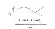
この間、制御部51は空気供給ブロア53のインバータ駆動部53aおよび空気排気ブロア63のインバータ駆動部63を駆動制御するとともに、空気供給ライン側弁機構54Aおよび空気排気ライン側弁機構64Aを駆動制御して、空間33内を微陰圧(炉本体5外部の環境(大気圧)に対して0Pa〜−85Pa、好ましくは−20Pa〜−30Pa)の範囲Aに維持する(図4参照)。 During this time, the
このように空間33内を炉本体5外部の環境(大気圧)に対して0Pa〜−85Pa、好ましくは−20Pa〜−30Paの微陰圧の範囲Aに保つことによって、空間33内が陽圧となって炉本体5から外部へ熱風が噴出することを防止することができ、かつ空間33内が強陰圧となって炉本体5内へ外気を巻き込み処理容器3において温度分布が不均一になることを防止することができる。 Thus, by keeping the inside of the
第1冷却工程によって炉本体5と処理容器3との間の空間33内が強制的に冷却されると、空間33内の温度が低下して、第1冷却工程中の圧力に比べて空間33内の圧力が低下する。 When the
この間、圧力検知システム50により空間33内の圧力が直接的に検知されており、制御部51は圧力検知システム50からの検知信号に基づいて、空間33内の圧力が第1冷却工程中の圧力に比べて大きく低下した場合、第1冷却工程中の設定圧力より大きな設定圧力として空気供給ブロア53のインバータ駆動部53aおよび空気排気ブロア63のインバータ駆動部63aを制御するとともに、空気供給ライン側弁機構54Aおよび空気排気ライン側弁機構64Aを駆動制御する。この場合、空間33内に空気供給ライン52から第1冷却工程時に比べて多量の冷却用空気を供給し、空間33内の圧力を再び第1冷却工程の圧力まで戻すことができる(第2冷却工程)。すなわち、このような第2冷却工程を採用しない場合、図4の破線に示すような圧力の低下が続いてしまうが、第2冷却工程を用いることにより、図4の実線に示すように、空間33内の圧力を再び第1冷却工程の水準まで戻すことができる。 During this time, the pressure in the
この第2冷却工程により、空間33内の圧力低下に伴って炉本体5内へ外気が巻込まれることはなく、また空間33内により多量の冷却用空気を供給することができ、空間33内を迅速かつ確実に強制冷却することができる。 By this second cooling step, the outside air is not entrained in the
次に第1冷却工程および第2冷却工程における作用について更に詳述する。 Next, the effect | action in a 1st cooling process and a 2nd cooling process is explained in full detail.
第1冷却工程において、上述のように環状流路38内の冷却用空気は断熱材16を貫通して設けられた空気吹出し孔40から炉本体5と処理容器3との間の空間33内に吹出されて、この空間33内を強制的に冷却する。この場合、空間33内に吹出された冷却用空気は炉本体5のヒータエレメント18および処理容器3を冷却して一気に膨張して体積が増加し、圧力が上昇する(図4参照)。上述のように圧力検知システム50は炉本体5と処理容器3との間の空間33に設けられ、この圧力検知システム50によって空間33内の圧力が直接的に検知されているため、例えば空間33から離れた空気供給ライン52あるいは空気排気ライン62に圧力センサを設けた場合に比べて、外乱の影響を受けることなく、空間33内の圧力上昇を迅速かつ確実に検知することができる。そして圧力検知システム50からの検知信号に基づいて空間33内が上記微陰圧となるよう制御部51が適切に制御する。 In the first cooling step, as described above, the cooling air in the
すなわち空間33内の圧力を空気供給ライン52あるいは空気排気ライン62に設置された圧力センサにより検知することも考えられるが、空気供給ライン52に圧力センサを設けると、冷却用空気に加わる押圧の影響を外乱として考慮する必要があり、空気排気ライン62に圧力センサを設けると冷却用空気に加わる引き圧の影響を外乱として考慮する必要がある。 In other words, the pressure in the
これに対して本発明によれば、炉本体5と処理容器3との間の空間33に圧力検知システム50を設置したので、外乱の影響を受けることなく、空間33の圧力上昇を直接的に迅速かつ確実に検知して、空間33内が微陰圧となるよう制御部51によって適切に制御することができる。 On the other hand, according to the present invention, since the
その後炉本体5と処理容器3との間の空間33が強制的に冷却されると、空間33内の温度が低下して空間33内の圧力も低下してくる(第2の冷却工程)(図4参照)。 Thereafter, when the
この場合も、空間33に設置した圧力検知システム50によって空間33内の圧力を直接的に検知するため、空間33内の圧力低下を迅速かつ確実に検知することができる。このとき制御部51は圧力検知システム50からの検知信号に基づいて、空間33内に空気供給ライン52から第1冷却工程時に比べて多量の冷却用空気を供給し、空間33内の圧力を再び第1冷却工程の圧力まで戻すことができる。 Also in this case, since the pressure in the
このように第2冷却工程時に、第1冷却工程時に比べて多量の冷却用空気を供給し、空間33内の圧力を上昇させることにより、第2冷却工程時において冷却速度が過度に低下することはない。 As described above, the cooling rate is excessively decreased in the second cooling step by supplying a larger amount of cooling air than in the first cooling step and increasing the pressure in the
なお、上記実施の形態において、圧力検知システム50からの検知信号に基づいて、制御部51が空気供給ブロア53のインバータ駆動部53a、空気排気ブロア63のインバータ駆動部63a、空気供給ライン側弁機構54Aおよび空気排気ライン側弁機構64Aを駆動制御する例を示したが、制御部51は空気供給ブロア53のインバータ駆動部53a、空気排気ブロア63のインバータ駆動部63a、空気供給ライン側弁機構54Aおよび空気排気ライン側弁機構64Aのいずれか一つを駆動制御してもよく、あるいはこれらを組合わせて制御してもよく、さらに空気供給ライン側弁機構54Aのいずれかの部材54,55,56のみを駆動制御してもよく、あるいは空気排気ライン側弁機構64Aのいずれかの部材64,65,66,67のみを駆動制御してもよい。 In the above embodiment, based on the detection signal from the
第2の実施の形態
次に図1および図3により本発明の第2の実施の形態について述べる。Second Embodiment Next, a second embodiment of the present invention will be described with reference to FIGS.
図1および図3に示すように、空気供給ライン52と空気排気ライン62は互いに連結されてクローズ系空気供給/排気ラインを構成している。すなわち空気排気ライン62は互いに連結され、連結部に空気供給および空気排気用のブロア73が設けられ、この空気供給ブロア73はインバータ駆動部73aを有している。 As shown in FIGS. 1 and 3, the
またブロア73の入口側にはバタフライ弁76および穴バルブ77が設けられ、ブロア73の出口側には、穴バルブ74およびバタフライ弁75が配置されている。これらブロア73の入口側のバタフライ弁76および穴バルブ77、およびブロア73の出口側の穴バルブ74およびバタフライ弁75はいずれも開閉調整自在となっており、空気供給ライン52側の穴バルブ74およびバタフライ弁75は空気供給ライン側弁機構74Aを構成している。 A
また空気排気ライン62側のバタフライ弁76および穴バルブ77は空気排気ライン側弁機構76Aを構成している。 The
次にこのような構成からなる縦型熱処理装置の作用について説明する。 Next, the operation of the vertical heat treatment apparatus having such a configuration will be described.
まず、ボート12内にウエハwが搭載され、ウエハwが搭載されたボート12が蓋体10の保温筒11上に載置される。その後蓋体10の上昇移動によりボート12が処理容器3内へ搬入される。 First, the wafer w is loaded in the
次に制御部51は電源を制御してヒータエレメント18を作動させ、炉本体5と処理用器3との間の空間33を加熱し、処理容器3内のボート12に搭載されたウエハwに対して必要な熱処理を施す。 Next, the
この間、温度センサからの検知信号に基づいて、制御部51によりウエハwに対して適切な温度をもって精度の良い熱処理が施される。 During this time, based on the detection signal from the temperature sensor, the
ウエハwに対する熱処理が終了すると、熱処理作業の効率化を図るため、炉本体5と処理容器3との間の空間33内を強制的に冷却する。 When the heat treatment on the wafer w is completed, the
次に空間33内の強制冷却方法について説明する。 Next, a forced cooling method in the
まず制御部51によって空気供給および空気排気用のブロア73が作動する。このとき空気供給ライン52内の冷却用空気が供給ダクト49へ送られる。 First, the air supply and
その後供給ダクト49内の冷却用空気は炉本体5の断熱材16外方に形成された各環状流路38内に進入し、次に環状流路38内の冷却用空気は断熱材16を貫通して設けられた空気吹出し孔40から炉本体5と処理容器3との間の空間33内に吹出されて、この空間33内を強制的に冷却する(第1冷却工程)。 Thereafter, the cooling air in the
空間33内の加熱空気は空気排気ライン62を経て、熱交換器79によって冷却された後、ブロア73に戻される。 The heated air in the
この間、制御部51はブロア73のインバータ駆動部73aを駆動制御するとともに、空気供給ライン側弁機構74Aおよび空気排気ライン側弁機構76Aを駆動制御して、空間33内を微陰圧(炉本体5外部の環境(大気圧)に対して0Pa〜−85Pa、好ましくは−20Pa〜−30Pa)の範囲Aに維持する(図4参照)。 During this time, the
このように空間33内を炉本体5外部の環境(大気圧)に対して0Pa〜−85Pa、好ましくは−20Pa〜−30Paの微陰圧の範囲Aに保つことによって、空間33内が陽圧となって炉本体5から外部へ熱風が噴出することを防止することができ、かつ空間33内が強陰圧となって炉本体5内へ外気を巻き込み処理容器3において温度分布が不均一になることを防止することができる。 Thus, by keeping the inside of the
第1冷却工程によって炉本体5と処理容器3との間の空間33内が強制的に冷却されると、空間33内の温度が低下して、第1冷却工程中の圧力に比べて空間33内の圧力が低下する。 When the
この間、圧力検知システム50により空間33内の圧力が直接的に検知されており、制御部51は圧力検知システム50からの検知信号に基づいて、空間33内の圧力が第1冷却工程中の圧力に比べて大きく低下した場合、第1冷却工程中の設定圧力より大きな設定圧力としてブロア73のインバータ駆動部73aを制御するとともに、空気供給ライン側弁機構74Aおよび空気排気ライン側弁機構76Aを駆動制御する。この場合、空間33内に空気供給ライン52から第1冷却工程時に比べて多量の冷却空気を供給し、空間33内の圧力を再び第1冷却工程の圧力まで戻すことができる(第2冷却工程)。すなわち、このような第2冷却工程を採用しない場合、図4の破線に示すような圧力の低下が続いてしまうが、第2冷却工程を用いることにより、図4の実線に示すように、空間33内の圧力を再び第1冷却工程の水準まで戻すことができる。 During this time, the pressure in the
この第2冷却工程により、空間33内の圧力低下に伴って炉本体5内へ外気が巻込まれることはなく、また空間33内により多量の冷却用空気を供給することができ、空間33内を迅速かつ確実に強制冷却することができる。 By this second cooling step, the outside air is not entrained in the
次に第1冷却工程および第2冷却工程における作用について更に詳述する。 Next, the effect | action in a 1st cooling process and a 2nd cooling process is explained in full detail.
第1冷却工程において、上述のように環状流路38内の冷却用空気は断熱材16を貫通して設けられた空気吹出し孔40から炉本体5と処理容器3との間の空間33内に吹出されて、この空間33内を強制的に冷却する。この場合、空間33内に吹出された冷却用空気は炉本体5のヒータエレメント18および処理容器3を冷却して一気に膨張して体積が増加し、圧力が上昇する(図4参照)。上述のように圧力検知システム50は炉本体5と処理容器3との間の空間33に設けられ、この圧力検知システム50によって空間33内の圧力が直接的に検知されているため、例えば空間33から離れた空気供給ライン52あるいは空気排気ライン62に圧力センサを設けた場合に比べて、外乱の影響を受けることなく、空間33内の圧力上昇を迅速かつ確実に検知することができる。そして圧力検知システム50からの検知信号に基づいて空間33内が上記微陰圧となるよう制御部51が適切に制御する。 In the first cooling step, as described above, the cooling air in the
すなわち空間33内の圧力を空気供給ライン52あるいは空気排気ライン62に設置された圧力センサにより検知することも考えられるが、空気供給ライン52に圧力センサを設けると、冷却用空気に加わる押圧の影響を外乱として考慮する必要があり、空気排気ライン62に圧力センサを設けると冷却用空気に加わる引き圧の影響を外乱として考慮する必要がある。 In other words, the pressure in the
これに対して本発明によれば、炉本体5と処理容器3との間の空間33に圧力検知システム50を設置したので、外乱の影響を受けることなく、空間33の圧力上昇を直接的に迅速かつ確実に検知して、空間33内が微陰圧となるよう制御部51によって適切に制御することができる。 On the other hand, according to the present invention, since the
その後炉本体5と処理容器3との間の空間33が強制的に冷却されると、空間33内の温度が低下して空間33内の圧力も低下してくる(第2の冷却工程)(図4参照)。 Thereafter, when the
この場合も、空間33に設置した圧力検知システム50によって空間33内の圧力を直接的に検知するため、空間33内の圧力低下を迅速かつ確実に検知することができる。このとき制御部51は圧力検知システム50からの検知信号に基づいて、空間33内に空気供給ライン52から第1冷却工程時に比べて多量の冷却用空気を供給し、空間33内の圧力を再び第1冷却工程の圧力まで戻すことができる。 Also in this case, since the pressure in the
このように第2冷却工程時に、第1冷却工程時に比べて多量の冷却用空気を供給し、空間33内の圧力を上昇させることにより、第2冷却工程時において冷却速度が過度に低下することはない。 As described above, the cooling rate is excessively decreased in the second cooling step by supplying a larger amount of cooling air than in the first cooling step and increasing the pressure in the
なお、上記実施の形態において、圧力検知システム50からの検知信号に基づいて、制御部51が空気供給および空気排気用のブロア73のインバータ駆動部73a、空気供給ライン側弁機構74Aおよび空気排気ライン側弁機構76Aを駆動制御する例を示したが、制御部51は空気供給および空気排気用のブロア73のインバータ駆動部73a、空気供給ライン側弁機構74Aおよび空気排気ライン側弁機構76Aのいずれか一つを駆動制御してもよく、あるいはこれらを組合わせて制御してもよく、さらに空気供給ライン側弁機構74Aのいずれかの部材74,75のみを駆動制御してもよく、あるいは空気排気ライン側弁機構76Aのいずれかの部材76,77のみを駆動制御してもよい。 In the above-described embodiment, based on the detection signal from the
なお、本発明は、上記各実施の形態に限定されるものではなく、本発明の要旨の範囲内で種々の設計変更が可能である。例えば、処理容器としては、導入管部及び排気管部を有する耐熱金属例えばステンレス鋼製の円筒状のマニホールドを下端部に接続してなるものであってもよく、また、二重管構造であってもよい。 The present invention is not limited to the embodiments described above, and various design changes can be made within the scope of the gist of the present invention. For example, the processing container may be formed by connecting a cylindrical manifold made of a heat-resistant metal such as stainless steel having an introduction pipe part and an exhaust pipe part to the lower end part, and has a double pipe structure. May be.
w 半導体ウエハ(被処理体)
1 縦型熱処理装置
2 熱処理炉
3 処理容器
3a 炉口
5 炉本体
16 断熱材
17 棚部
18 ヒータエレメント(発熱抵抗体)
33 空間
40 強制空冷用空気吹出し孔
49 供給ダクト
50 圧力検知システム
51 制御部
52 空気供給ライン
53 空気供給ブロア
53a インバータ駆動部
54 穴バルブ
54A 空気供給ライン側弁機構
55 バタフライ弁
56 ダンパ
62 空気排気ライン
63 空気排気ブロア
63a インバータ駆動部
64 穴バルブ
65 バタフライ弁
66 バタフライ弁
67 穴バルブ
73 空気供給および空気排気用ブロア
73a インバータ駆動部
74 穴バルブ
74A 空気供給ライン側弁機構
75 バタフライ弁
76 バタフライ弁
76A 空気排気ライン側弁機構
77 穴バルブw Semiconductor wafer (object to be processed)
DESCRIPTION OF SYMBOLS 1 Vertical
33
Claims (16)
Translated fromJapanese炉本体内に配置され、炉本体との間に空間を形成するとともに、内部に複数の被処理体を収納する処理容器と、
炉本体に縦方向に並んで設けられた複数の空気吹出し孔と、
炉本体に接続され、複数の空気吹出し孔を介して空間内に冷却用空気を供給する空気供給ラインと、
炉本体に接続され、空間内から冷却用空気を排気する空気排気ラインと、
空気供給ラインおよび空気排気ラインの少なくとも一方に設けられたブロアと、
空気供給ラインおよび空気排気ラインに各々設けられた空気供給ライン側弁機構および空気排気ライン側弁機構と、
炉本体と処理容器との間の空間内の圧力を検知する圧力検知システムと、
圧力検知システムからの検知信号に基づいて、ブロア、空気供給ライン側弁機構および空気排気ライン側弁機構のうち少なくとも一方を制御して空間内の圧力を微陰圧とする制御部とを備え、
複数の空気吹き出し孔によって炉本体に縦方向に延びる空気吹き出し孔の設置領域が形成され、圧力検知システムは、炉本体と処理容器との間の空間のうち、炉本体に縦方向に延びて形成された空気吹出し孔の設置領域に対応する空間領域に設けられていることを特徴とする縦型熱処理装置。A furnace body provided with a heating section on the inner peripheral surface;
A processing vessel that is disposed in the furnace body, forms a space between the furnace body, and stores a plurality of objects to be processed therein,
A plurality of air blowing holes provided in the furnace body in thevertical direction ;
An air supply line connected to the furnace body and supplying cooling air into the space through a plurality of air blowing holes;
An air exhaust line connected to the furnace body and exhausting cooling air from the space;
A blower provided in at least one of the air supply line and the air exhaust line;
An air supply line side valve mechanism and an air exhaust line side valve mechanism respectively provided in the air supply line and the air exhaust line;
A pressure detection system for detecting the pressure in the space between the furnace body and the processing vessel;
A control unit that controls at least one of the blower, the air supply line side valve mechanism, and the air exhaust line side valve mechanism based on a detection signal from the pressure detection system to make the pressure in the space a slight negative pressure;
A plurality of air blowing holes form an air blowing hole installation region extending in the vertical direction in the furnace body, and the pressure detection system isformed extending in the furnace body in the vertical direction in the space between the furnace body and the processing vessel. A vertical heat treatment apparatus, wherein the vertical heat treatment apparatus is provided in a space region corresponding to an installation region ofthe air blowing holes.
当該クローズ系空気ラインに、空気供給および空気排気用のブロアが設けられていることを特徴とする請求項1記載の縦型熱処理装置。The air supply line and the air exhaust line are connected to each other to form a closed system air supply / exhaust line,
2. The vertical heat treatment apparatus according to claim 1, wherein the closed system air line is provided with a blower for air supply and air exhaust.
空気供給ラインに空気供給ブロアが設けられ、空気排気ラインに空気排気ブロアが設けられていることを特徴とする請求項1記載の縦型熱処理装置。The air supply line and the air exhaust line are provided independently to constitute an open system air supply / exhaust line,
The vertical heat treatment apparatus according to claim 1, wherein an air supply blower is provided in the air supply line, and an air exhaust blower is provided in the air exhaust line.
炉本体内に配置され、炉本体との間に空間を形成するとともに、内部に複数の被処理体を収納する処理容器と、
炉本体に縦方向に並んで設けられた複数の空気吹出し孔と、
炉本体に接続され、複数の空気吹出し孔を介して空間内に冷却用空気を供給する空気供給ラインと、
炉本体に接続され、空間内から冷却用空気を排気する空気排気ラインと、
空気供給ラインおよび空気排気ラインの少なくとも一方に設けられたブロアと、
空気供給ラインおよび空気排気ラインに各々設けられた空気供給ライン側弁機構および空気排気ライン側弁機構と、
炉本体と処理容器との間の空間内の圧力を検知する圧力検知システムと、
圧力検知システムからの検知信号に基づいて、ブロア、空気供給ライン側弁機構および空気排気ライン側弁機構のうち少なくとも一方を制御して空間内の圧力を微陰圧とする制御部とを備え、複数の空気吹き出し孔によって炉本体に縦方向に延びる空気吹き出し孔の設置領域が形成され、圧力検知システムは、炉本体と処理容器との間の空間のうち、炉本体に縦方向に延びて形成された空気吹出し孔の設置領域に対応する空間領域に設けられていることを特徴とする縦型熱処理装置の冷却方法において、
制御部によってブロアが作動し、空気供給ラインにより炉本体と処理容器との間の空間に冷却用空気を供給するとともに、空間から空気排気ラインにより冷却用空気を排気する第1冷却工程と、
制御部によって圧力検知システムからの検知信号に基づいて、空間内の温度低下により第1冷却工程の時に比べて圧力が低下した場合、ブロア、空気供給ライン側弁機構および空気排気ライン側弁機構のうち少なくとも一方が制御されて、第1冷却工程時の空気量より大きな空気量を空間内へ供給する第2冷却工程と、を備えたことを特徴とする縦型熱処理装置の冷却方法。A furnace body provided with a heating section on the inner peripheral surface;
A processing vessel that is disposed in the furnace body, forms a space between the furnace body, and stores a plurality of objects to be processed therein,
A plurality of air blowing holes provided in the furnace body in thevertical direction ;
An air supply line connected to the furnace body and supplying cooling air into the space through a plurality of air blowing holes;
An air exhaust line connected to the furnace body and exhausting cooling air from the space;
A blower provided in at least one of the air supply line and the air exhaust line;
An air supply line side valve mechanism and an air exhaust line side valve mechanism respectively provided in the air supply line and the air exhaust line;
A pressure detection system for detecting the pressure in the space between the furnace body and the processing vessel;
A control unit that controls at least one of the blower, the air supply line side valve mechanism, and the air exhaust line side valve mechanism based on a detection signal from the pressure detection system to make the pressure in the space a slight negative pressure;A plurality of air blowing holes form an air blowing hole installation region extending in the vertical direction in the furnace body, and the pressure detection system isformed extending in the furnace body in the vertical direction in the space between the furnace body and the processing vessel.In the cooling method of the vertical heat treatment apparatus, which is provided in a space region corresponding to the installation region ofthe air blowing holes made,
A first cooling step in which the blower is operated by the control unit, supplying cooling air to the space between the furnace main body and the processing container by the air supply line, and exhausting the cooling air from the space by the air exhaust line;
Based on the detection signal from the pressure detection system by the control unit, when the pressure drops compared to the time of the first cooling process due to the temperature drop in the space, the blower, the air supply line side valve mechanism and the air exhaust line side valve mechanism A cooling method for a vertical heat treatment apparatus, comprising: a second cooling step in which at least one of them is controlled to supply an air amount larger than the air amount in the first cooling step into the space.
当該クローズ系空気ラインに、空気供給および空気排気用のブロアが設けられていることを特徴とする請求項9記載の縦型熱処理装置の冷却方法。The air supply line and the air exhaust line are connected to each other to form a closed system air supply / exhaust line,
10. The cooling method for a vertical heat treatment apparatus according to claim 9, wherein a blower for supplying air and exhausting air is provided in the closed system air line.
空気供給ラインに空気供給ブロアが設けられ、空気排気ラインに空気排気ブロアが設けられていることを特徴とする請求項9記載の縦型熱処理装置の冷却方法。The air supply line and the air exhaust line are provided independently to constitute an open system air supply / exhaust line,
The cooling method for a vertical heat treatment apparatus according to claim 9, wherein an air supply blower is provided in the air supply line, and an air exhaust blower is provided in the air exhaust line.
Priority Applications (1)
| Application Number | Priority Date | Filing Date | Title |
|---|---|---|---|
| JP2010281622AJP5394360B2 (en) | 2010-03-10 | 2010-12-17 | Vertical heat treatment apparatus and cooling method thereof |
Applications Claiming Priority (3)
| Application Number | Priority Date | Filing Date | Title |
|---|---|---|---|
| JP2010053154 | 2010-03-10 | ||
| JP2010053154 | 2010-03-10 | ||
| JP2010281622AJP5394360B2 (en) | 2010-03-10 | 2010-12-17 | Vertical heat treatment apparatus and cooling method thereof |
Publications (2)
| Publication Number | Publication Date |
|---|---|
| JP2011211163A JP2011211163A (en) | 2011-10-20 |
| JP5394360B2true JP5394360B2 (en) | 2014-01-22 |
Family
ID=44560331
Family Applications (1)
| Application Number | Title | Priority Date | Filing Date |
|---|---|---|---|
| JP2010281622AActiveJP5394360B2 (en) | 2010-03-10 | 2010-12-17 | Vertical heat treatment apparatus and cooling method thereof |
Country Status (5)
| Country | Link |
|---|---|
| US (1) | US9099507B2 (en) |
| JP (1) | JP5394360B2 (en) |
| KR (1) | KR101360069B1 (en) |
| CN (1) | CN102191473B (en) |
| TW (1) | TWI497023B (en) |
Families Citing this family (31)
| Publication number | Priority date | Publication date | Assignee | Title |
|---|---|---|---|---|
| US9608119B2 (en) | 2010-03-02 | 2017-03-28 | Micron Technology, Inc. | Semiconductor-metal-on-insulator structures, methods of forming such structures, and semiconductor devices including such structures |
| JP5394292B2 (en)* | 2010-03-12 | 2014-01-22 | 東京エレクトロン株式会社 | Vertical heat treatment equipment and pressure sensing system / temperature sensor combination |
| CN102517562B (en)* | 2011-12-15 | 2014-01-01 | 常州星海电子有限公司 | Device for manufacturing thin-film battery in way of vertical gradient condensation |
| US9638466B2 (en)* | 2012-12-28 | 2017-05-02 | Jonathan Y. MELLEN | Furnace system with active cooling system and method |
| US20160208373A1 (en)* | 2015-01-20 | 2016-07-21 | Kennametal Inc. | Imc evaporator boat assembly |
| US10184168B2 (en)* | 2015-01-20 | 2019-01-22 | Kennametal Inc. | IMC evaporator boat-thermal insulation cartridge assembly |
| CN104576463A (en)* | 2015-01-22 | 2015-04-29 | 北京七星华创电子股份有限公司 | Rapid cooling and heat treatment system |
| KR101720620B1 (en)* | 2015-04-21 | 2017-03-28 | 주식회사 유진테크 | Substrate Processing Apparatus and Method of Cleaning Chamber |
| US20170207078A1 (en)* | 2016-01-15 | 2017-07-20 | Taiwan Semiconductor Manufacturing Co., Ltd. | Atomic layer deposition apparatus and semiconductor process |
| JP6804309B2 (en)* | 2017-01-12 | 2020-12-23 | 東京エレクトロン株式会社 | Heat treatment equipment and temperature control method |
| JP6964737B2 (en)* | 2017-01-12 | 2021-11-10 | 東京エレクトロン株式会社 | Heat treatment equipment and temperature control method |
| CN107815530A (en)* | 2017-11-30 | 2018-03-20 | 中国石油天然气第七建设有限公司 | Pin-connected panel heat-treatment furnace |
| CN110106334B (en) | 2018-02-01 | 2021-06-22 | 福建省长汀金龙稀土有限公司 | Device and method for continuously performing grain boundary diffusion and heat treatment |
| WO2019148918A1 (en)* | 2018-02-01 | 2019-08-08 | 福建省长汀金龙稀土有限公司 | Device and method for continuously performing grain boundary diffusion and heat treatment |
| CN108489278A (en)* | 2018-03-20 | 2018-09-04 | 佛山市阳光陶瓷有限公司 | A kind of ventilation heat radiating type kiln |
| CN110527989A (en)* | 2018-06-08 | 2019-12-03 | 北京北方华创微电子装备有限公司 | Cooling device and Equipment for Heating Processing for Equipment for Heating Processing |
| JP7055075B2 (en)* | 2018-07-20 | 2022-04-15 | 東京エレクトロン株式会社 | Heat treatment equipment and heat treatment method |
| KR102412459B1 (en)* | 2018-07-26 | 2022-06-23 | 주식회사 원익아이피에스 | Vertical reactor for wafer processing |
| CN109532032A (en)* | 2018-11-23 | 2019-03-29 | 承德石油高等专科学校 | A kind of temperature testing equipment of thermoplastic pipe's butt fusion welding machine heating plate |
| CN109234704A (en)* | 2018-11-27 | 2019-01-18 | 湖南顶立科技有限公司 | A kind of vapor deposition apparatus |
| JP7101599B2 (en)* | 2018-11-27 | 2022-07-15 | 東京エレクトロン株式会社 | Heat treatment equipment and heat treatment method |
| RU2705186C1 (en)* | 2019-01-14 | 2019-11-05 | Общество с ограниченной ответственностью "Катод" | Method of workpiece cooling in vacuum heating chamber of vacuum furnace and vacuum furnace |
| DE102019110950A1 (en) | 2019-04-29 | 2020-10-29 | Kennametal Inc. | Hard metal compositions and their applications |
| KR102552458B1 (en)* | 2019-07-31 | 2023-07-06 | 가부시키가이샤 코쿠사이 엘렉트릭 | Substrate processing apparatus, substrate support, and method of manufacturing semiconductor device |
| CN110634775B (en)* | 2019-09-16 | 2022-11-08 | 西安奕斯伟材料科技有限公司 | Airflow control device and wafer processing device |
| CN110749203A (en)* | 2019-09-29 | 2020-02-04 | 彩虹显示器件股份有限公司 | Furnace body cooling system of substrate glass kiln and operation method thereof |
| CN111023841B (en)* | 2019-12-26 | 2023-09-08 | 北京北方华创微电子装备有限公司 | Furnace body cooling device and semiconductor processing equipment |
| CN112646987A (en)* | 2020-12-01 | 2021-04-13 | 攀钢集团研究院有限公司 | Preparation method of industrial smelting vanadium-aluminum alloy |
| CN112662970A (en)* | 2020-12-03 | 2021-04-16 | 上海航天精密机械研究所 | Environment-friendly magnesium alloy part heat treatment method and device |
| CN113430350B (en)* | 2021-08-02 | 2024-12-06 | 江苏石川岛丰东真空技术有限公司 | Vertical furnace bottom cover structure for heat treatment and vertical vacuum furnace |
| CN115911616B (en)* | 2022-12-08 | 2025-09-19 | 宁德时代新能源科技股份有限公司 | Method, apparatus, device and storage medium for exhausting formation process of battery |
Family Cites Families (55)
| Publication number | Priority date | Publication date | Assignee | Title |
|---|---|---|---|---|
| US2440052A (en)* | 1945-09-24 | 1948-04-20 | Ruth Sharp Lingen | Averaging controller |
| US3794459A (en)* | 1972-11-29 | 1974-02-26 | Meenan Corp | Furnace exhaust treatment system |
| US4697530A (en)* | 1986-12-23 | 1987-10-06 | Dumont Holding Company | Underfed stoker boiler for burning bituminous coal and other solid fuel particles |
| US5249960A (en)* | 1991-06-14 | 1993-10-05 | Tokyo Electron Sagami Kabushiki Kaisha | Forced cooling apparatus for heat treatment apparatus |
| US5447294A (en)* | 1993-01-21 | 1995-09-05 | Tokyo Electron Limited | Vertical type heat treatment system |
| KR100221983B1 (en)* | 1993-04-13 | 1999-09-15 | 히가시 데쓰로 | A treating apparatus for semiconductor process |
| JP3111395B2 (en)* | 1993-06-15 | 2000-11-20 | 東京エレクトロン株式会社 | Heat treatment equipment |
| US5616264A (en)* | 1993-06-15 | 1997-04-01 | Tokyo Electron Limited | Method and apparatus for controlling temperature in rapid heat treatment system |
| KR100264445B1 (en)* | 1993-10-04 | 2000-11-01 | 히가시 데쓰로 | Plasma Treatment Equipment |
| JPH0982720A (en)* | 1995-09-14 | 1997-03-28 | Tokyo Electron Ltd | Vertical heat treatment apparatus |
| JPH09190982A (en)* | 1996-01-11 | 1997-07-22 | Toshiba Corp | Semiconductor manufacturing equipment |
| TW317644B (en)* | 1996-01-26 | 1997-10-11 | Tokyo Electron Co Ltd | |
| US6059567A (en)* | 1998-02-10 | 2000-05-09 | Silicon Valley Group, Inc. | Semiconductor thermal processor with recirculating heater exhaust cooling system |
| US6191394B1 (en)* | 1999-05-19 | 2001-02-20 | Tokyo Electron Ltd. | Heat treating apparatus |
| JP4578615B2 (en)* | 1999-07-21 | 2010-11-10 | 東京エレクトロン株式会社 | Heat treatment equipment |
| US6394796B1 (en)* | 1999-11-04 | 2002-05-28 | Alan D. Smith | Curing oven combining methods of heating |
| TW536604B (en)* | 2000-10-02 | 2003-06-11 | Ebara Corp | Combustion type waste gas treatment system |
| US6729041B2 (en)* | 2000-12-28 | 2004-05-04 | Tokyo Electron Limited | Substrate processing apparatus and substrate processing method |
| JP4610771B2 (en)* | 2001-04-05 | 2011-01-12 | 東京エレクトロン株式会社 | Vertical heat treatment apparatus and forced air cooling method thereof |
| CN100456435C (en)* | 2004-11-01 | 2009-01-28 | 株式会社日立国际电气 | Substrate processing apparatus and method for manufacturing semiconductor device |
| US7753678B2 (en)* | 2005-06-10 | 2010-07-13 | Nucor Corporation | Method and apparatus for producing charcoal |
| US20090209095A1 (en)* | 2005-06-22 | 2009-08-20 | Sadayoshi Horii | Manufacturing Method for Semiconductor Devices and Substrate Processing Apparatus |
| WO2007018016A1 (en)* | 2005-08-05 | 2007-02-15 | Hitachi Kokusai Electric Inc. | Substrate processing equipment, cooling gas supply nozzle and method for fabricating semiconductor device |
| KR101003446B1 (en)* | 2006-03-07 | 2010-12-28 | 가부시키가이샤 히다치 고쿠사이 덴키 | Substrate processing apparatus and substrate processing method |
| US20090064765A1 (en)* | 2006-03-28 | 2009-03-12 | Hitachi Kokusai Electric Inc. | Method of Manufacturing Semiconductor Device |
| WO2007132884A1 (en)* | 2006-05-17 | 2007-11-22 | Hitachi Kokusai Electric Inc. | Semiconductor device manufacturing method and substrate processing apparatus |
| US7869888B2 (en)* | 2006-05-31 | 2011-01-11 | Tokyo Electron Limited | Information processing apparatus, semiconductor manufacturing system, information processing method, and storage medium |
| JP4809175B2 (en)* | 2006-09-28 | 2011-11-09 | 株式会社日立国際電気 | Manufacturing method of semiconductor device |
| JP4669465B2 (en)* | 2006-11-08 | 2011-04-13 | 株式会社日立国際電気 | Substrate processing apparatus, semiconductor device manufacturing method, heating apparatus, and heat insulating material |
| US20080173238A1 (en)* | 2006-12-12 | 2008-07-24 | Hitachi Kokusai Electric Inc. | Substrate processing apparatus, method of manufacturing semiconductor device, and reaction vessel |
| US7727780B2 (en)* | 2007-01-26 | 2010-06-01 | Hitachi Kokusai Electric Inc. | Substrate processing method and semiconductor manufacturing apparatus |
| JP5312765B2 (en) | 2007-01-26 | 2013-10-09 | 株式会社日立国際電気 | Substrate processing method and semiconductor manufacturing apparatus |
| KR100796767B1 (en)* | 2007-02-28 | 2008-01-22 | 최병길 | Heat treatment device to minimize atmospheric gas consumption and minimize carbon dioxide gas generation |
| US8367560B2 (en)* | 2007-06-15 | 2013-02-05 | Hitachi Kokusai Electric Inc. | Semiconductor device manufacturing method |
| JP5510991B2 (en) | 2007-09-06 | 2014-06-04 | 株式会社日立国際電気 | Semiconductor manufacturing apparatus and substrate processing method |
| US20090095422A1 (en)* | 2007-09-06 | 2009-04-16 | Hitachi Kokusai Electric Inc. | Semiconductor manufacturing apparatus and substrate processing method |
| US20090308332A1 (en)* | 2007-10-01 | 2009-12-17 | Tanbour Emadeddin Y | Water heater with forced draft air inlet |
| US20090197424A1 (en)* | 2008-01-31 | 2009-08-06 | Hitachi Kokusai Electric Inc. | Substrate processing apparatus and method for manufacturing semiconductor device |
| JP5237133B2 (en)* | 2008-02-20 | 2013-07-17 | 株式会社日立国際電気 | Substrate processing equipment |
| US8293592B2 (en)* | 2008-04-16 | 2012-10-23 | Hitachi Kokusai Electric Inc. | Method of manufacturing semiconductor device and substrate processing apparatus |
| JP2010153467A (en)* | 2008-12-24 | 2010-07-08 | Hitachi Kokusai Electric Inc | Substrate processing apparatus, and method of manufacturing semiconductor device |
| JP5658463B2 (en)* | 2009-02-27 | 2015-01-28 | 株式会社日立国際電気 | Substrate processing apparatus and semiconductor device manufacturing method |
| JP5394292B2 (en)* | 2010-03-12 | 2014-01-22 | 東京エレクトロン株式会社 | Vertical heat treatment equipment and pressure sensing system / temperature sensor combination |
| JP5405667B2 (en)* | 2010-07-22 | 2014-02-05 | 株式会社日立国際電気 | Substrate processing apparatus and semiconductor device manufacturing method |
| JP2012049342A (en)* | 2010-08-27 | 2012-03-08 | Hitachi Kokusai Electric Inc | Apparatus and method of processing substrate |
| US8866271B2 (en)* | 2010-10-07 | 2014-10-21 | Hitachi Kokusai Electric Inc. | Semiconductor device manufacturing method, substrate processing apparatus and semiconductor device |
| TWI562204B (en)* | 2010-10-26 | 2016-12-11 | Hitachi Int Electric Inc | Substrate processing apparatus, semiconductor device manufacturing method and computer-readable recording medium |
| JP5722595B2 (en)* | 2010-11-11 | 2015-05-20 | 株式会社日立国際電気 | Substrate processing apparatus and semiconductor device manufacturing method |
| JP5722008B2 (en)* | 2010-11-24 | 2015-05-20 | 株式会社日立国際電気 | Semiconductor device manufacturing method, semiconductor device, and substrate processing apparatus |
| JP5696576B2 (en)* | 2011-04-25 | 2015-04-08 | 東京エレクトロン株式会社 | Temperature measuring substrate and heat treatment apparatus |
| JP2013062361A (en)* | 2011-09-13 | 2013-04-04 | Tokyo Electron Ltd | Heat treatment apparatus, temperature control system, heat treatment method, temperature control method, and record medium recording program for executing heat treatment method or temperature control method |
| TWI534341B (en)* | 2011-09-26 | 2016-05-21 | Hitachi Int Electric Inc | A substrate processing apparatus, a manufacturing method of a semiconductor device, and a recording medium |
| JP6038043B2 (en)* | 2011-11-21 | 2016-12-07 | 株式会社日立国際電気 | Substrate processing apparatus, semiconductor device manufacturing method, and program |
| JP6170847B2 (en)* | 2013-03-25 | 2017-07-26 | 株式会社日立国際電気 | Thermal insulation structure, heating apparatus, substrate processing apparatus, and semiconductor device manufacturing method |
| JP2014192485A (en)* | 2013-03-28 | 2014-10-06 | Hitachi Kokusai Electric Inc | Semiconductor device manufacturing method, substrate processing method and substrate processing apparatus |
- 2010
- 2010-12-17JPJP2010281622Apatent/JP5394360B2/enactiveActive
- 2011
- 2011-02-24KRKR1020110016384Apatent/KR101360069B1/enactiveActive
- 2011-03-04USUS13/040,720patent/US9099507B2/enactiveActive
- 2011-03-08TWTW100107759Apatent/TWI497023B/enactive
- 2011-03-10CNCN201110057683.0Apatent/CN102191473B/enactiveActive
Also Published As
| Publication number | Publication date |
|---|---|
| CN102191473B (en) | 2014-11-19 |
| KR101360069B1 (en) | 2014-02-07 |
| TWI497023B (en) | 2015-08-21 |
| CN102191473A (en) | 2011-09-21 |
| US20110223552A1 (en) | 2011-09-15 |
| US9099507B2 (en) | 2015-08-04 |
| JP2011211163A (en) | 2011-10-20 |
| KR20110102168A (en) | 2011-09-16 |
| TW201200831A (en) | 2012-01-01 |
Similar Documents
| Publication | Publication Date | Title |
|---|---|---|
| JP5394360B2 (en) | Vertical heat treatment apparatus and cooling method thereof | |
| JP5394292B2 (en) | Vertical heat treatment equipment and pressure sensing system / temperature sensor combination | |
| TWI401728B (en) | Heat treatment furnace and vertical heat treatment device | |
| JP4365017B2 (en) | Method for controlling temperature drop rate of heat treatment apparatus and heat treatment apparatus | |
| US9748122B2 (en) | Thermal processing apparatus and method of controlling the same | |
| JP7055075B2 (en) | Heat treatment equipment and heat treatment method | |
| JP2012080080A (en) | Vertical heat treatment apparatus and control method therefor | |
| US8253075B2 (en) | Heat treatment apparatus, heater, and method for manufacturing the heater | |
| JP5868619B2 (en) | Heat treatment furnace and heat treatment apparatus | |
| EP1895575B1 (en) | Heat treatment apparatus | |
| JP5770042B2 (en) | Heat treatment equipment | |
| JP4610771B2 (en) | Vertical heat treatment apparatus and forced air cooling method thereof | |
| KR101512874B1 (en) | Vertical heat processing apparatus and control method of the same | |
| JP5743788B2 (en) | Heat treatment equipment | |
| JP2023152674A (en) | Processing device and temperature adjustment method | |
| JP5274696B2 (en) | Thermal insulation structure, heating apparatus, heating system, substrate processing apparatus, and semiconductor device manufacturing method |
Legal Events
| Date | Code | Title | Description |
|---|---|---|---|
| A621 | Written request for application examination | Free format text:JAPANESE INTERMEDIATE CODE: A621 Effective date:20120918 | |
| A977 | Report on retrieval | Free format text:JAPANESE INTERMEDIATE CODE: A971007 Effective date:20130718 | |
| A131 | Notification of reasons for refusal | Free format text:JAPANESE INTERMEDIATE CODE: A131 Effective date:20130723 | |
| A521 | Request for written amendment filed | Free format text:JAPANESE INTERMEDIATE CODE: A523 Effective date:20130902 | |
| TRDD | Decision of grant or rejection written | ||
| A01 | Written decision to grant a patent or to grant a registration (utility model) | Free format text:JAPANESE INTERMEDIATE CODE: A01 Effective date:20130920 | |
| A61 | First payment of annual fees (during grant procedure) | Free format text:JAPANESE INTERMEDIATE CODE: A61 Effective date:20131016 | |
| R150 | Certificate of patent or registration of utility model | Free format text:JAPANESE INTERMEDIATE CODE: R150 Ref document number:5394360 Country of ref document:JP Free format text:JAPANESE INTERMEDIATE CODE: R150 | |
| R250 | Receipt of annual fees | Free format text:JAPANESE INTERMEDIATE CODE: R250 | |
| R250 | Receipt of annual fees | Free format text:JAPANESE INTERMEDIATE CODE: R250 | |
| R250 | Receipt of annual fees | Free format text:JAPANESE INTERMEDIATE CODE: R250 | |
| R250 | Receipt of annual fees | Free format text:JAPANESE INTERMEDIATE CODE: R250 | |
| R250 | Receipt of annual fees | Free format text:JAPANESE INTERMEDIATE CODE: R250 | |
| R250 | Receipt of annual fees | Free format text:JAPANESE INTERMEDIATE CODE: R250 | |
| R250 | Receipt of annual fees | Free format text:JAPANESE INTERMEDIATE CODE: R250 | |
| R250 | Receipt of annual fees | Free format text:JAPANESE INTERMEDIATE CODE: R250 |