JP5393255B2 - Sample transport system - Google Patents
Sample transport systemDownload PDFInfo
- Publication number
- JP5393255B2 JP5393255B2JP2009123679AJP2009123679AJP5393255B2JP 5393255 B2JP5393255 B2JP 5393255B2JP 2009123679 AJP2009123679 AJP 2009123679AJP 2009123679 AJP2009123679 AJP 2009123679AJP 5393255 B2JP5393255 B2JP 5393255B2
- Authority
- JP
- Japan
- Prior art keywords
- transport system
- holder
- sample
- specimen
- test tube
- Prior art date
- Legal status (The legal status is an assumption and is not a legal conclusion. Google has not performed a legal analysis and makes no representation as to the accuracy of the status listed.)
- Active
Links
Images


Landscapes
- Automatic Analysis And Handling Materials Therefor (AREA)
Description
Translated fromJapanese本発明は、血液等の検体を搬送するシステムにおいて、検体の分取または分注,分析を行うために検体を搬送する場合等において用いられる技術に関する。 The present invention relates to a technique used in a system for transporting a specimen such as blood in the case of transporting a specimen in order to sort, dispense, or analyze a specimen.
血液等の検体を収容する試験管はガラス及び樹脂製である。この試験管に収容された検体を搬送するには、垂直保持可能なホルダー及びラックなどに載せて、ベルトライン等で運ぶのが一般的である。 A test tube for storing a specimen such as blood is made of glass and resin. In order to transport the sample contained in the test tube, it is generally carried on a holder or rack that can be held vertically and carried by a belt line or the like.
また、径や長さの異なる試験管を保持するにはこれまで多種多様なホルダー,ラックが考案されている(例えば、特許文献1参照)。 Various holders and racks have been devised so far to hold test tubes having different diameters and lengths (see, for example, Patent Document 1).
これらは搬送系ガイドレールに係合可能な環状溝を有しており試験管を収容するための円筒形の中空を有し、数本のばね鋼線やスペーサなどで構成されていることで知られている。 These have an annular groove that can be engaged with the guide rail of the transport system, have a cylindrical hollow to accommodate the test tube, and are known to be composed of several spring steel wires and spacers. It has been.
従来のホルダー(特許文献1)の試験管保持部は2ケのばね鋼線がホルダーの円筒形中空部の底に十字状に交差させて配置され、そこから上方へ突出させて試験管保持部を形成している。このような構成では、それらを固定するためにスペーサ等別部品を使用する必要がある。部品点数が増えることになりコストの面で不利である。 The test tube holding part of the conventional holder (Patent Document 1) has two spring steel wires arranged in a cross shape at the bottom of the cylindrical hollow part of the holder and protrudes upward from the bottom of the cylindrical hollow part of the holder. Is forming. In such a configuration, it is necessary to use a separate part such as a spacer to fix them. The number of parts increases, which is disadvantageous in terms of cost.
また、ホルダーの部材に使用されている材質に帯電防止機能が無いため、冬場など乾燥する季節は動作中の摩擦などでホルダーが帯電する場合が予想され、除電ブラシなどで除電する必要がある。ホルダーが帯電すると、保持されている試験管に収容されている試料を分注する際、静電容量方式を利用して試験管から試料を分取りする方式の分注機は、分注ノズルのホバリング(空中停止)等の誤動作する可能性があり、信頼性が低いなどの問題があった。 In addition, since the material used for the member of the holder has no antistatic function, it is expected that the holder will be charged due to friction during operation in the dry season such as winter, and it is necessary to remove electricity with a static elimination brush. When the holder is charged, when dispensing the sample contained in the held test tube, the dispenser that dispenses the sample from the test tube using the capacitance method There was a possibility of malfunction such as hovering (stop in the air), and there were problems such as low reliability.
検体の搬送の面では、検体の前処理終了後の各分析ユニットへの搬送時に、同じベルトライン上に試験管ホルダーと試験管ラック(例:5本ラック)が混在することが考慮されていないため、それぞれ別のベルトラインが必要となり、制御及び構造が複雑となる。また、システム全体としてのコストアップにも繋がる問題があった。 In terms of sample transport, it is not considered that test tube holders and test tube racks (eg, 5 racks) coexist on the same belt line when transporting to each analysis unit after sample pretreatment is completed. For this reason, separate belt lines are required, and the control and structure are complicated. There is also a problem that leads to an increase in the cost of the entire system.
さらにシステム制御の動力源としてエアシリンダーなど圧縮空気を利用して駆動している場合もあるが、これを使用するとなると、エアコンプレッサーなどの機器類が別途必要になりこれもまたコストアップ及びシステムの占有面積の増大の要因となる。 Furthermore, there are cases where the system is driven by using compressed air such as an air cylinder as a power source for system control. However, if this is used, equipment such as an air compressor is required separately, which also increases costs and increases the system's power. This increases the occupied area.
この発明は前記課題を解決するために、試験管を収納可能な円筒形の中空を有し、倒れ防止用のガイド部を有するホルダー1と、試験管を保持するために円形に成形されたアダプタと、前記アダプタを前記ホルダー1に取り付け時に前記アダプタが外れないよう押さえることを目的とした前記ホルダー1と同様な円筒形状を有するホルダー2から構成され、前記アダプタは一定の長さの細い板状の弾性力のある形状をした複数の金属が、ある一定の間隔で連続して突出しており、各板状の金属は底部では一体となっており、円形状に一体で形成されている。 In order to solve the above-mentioned problems, the present invention provides a
また、前記ホルダー1と前記ホルダー2は熱可塑性の樹脂製であり、二つは超音波溶着法等で接合されている。 The
さらに、静電対策として帯電防止,導電性に優れた材料を使用している。 Furthermore, materials with excellent antistatic and electrical conductivity are used as countermeasures against static electricity.
また、前記ホルダー1は前記アダプタが容易に装着することを可能とするため、金属板の厚さと同等な厚さの溝加工を有し、形状の異なる試験管を収納,保持が可能な試験管ホルダーを使用することとした。 In addition, the
さらに前記試験管ホルダーと同様に試験管を収納可能な試験管ラック(例:5本ラック)が同じベルトライン上で混在、動作することを可能とし、システムの動力源は全て電力のみで駆動可能な機構及び装置を使用することにより、エアコンプレッサーによる圧縮空気などを使用しなくてもシステムを実現することができる。 In addition, test tube racks (for example, 5 racks) that can store test tubes can be mixed and operated on the same belt line in the same way as the test tube holder, and all system power sources can be driven by electric power. By using a simple mechanism and apparatus, the system can be realized without using compressed air by an air compressor.
この発明によれば、下記の試験管ホルダー及び検体搬送システムを提供できる。
(1)形状の異なる検体の入った試験管を安定に保持し、且つ安価に製作が可能で帯電性に優れた信頼性の高い試験管ホルダー。
(2)試験管ホルダーと試験管ラックを同じ搬送ライン上に混在して目的の場所まで搬送することが可能な検体搬送システム。
(3)(2)の搬送ライン上で動力源としての圧縮空気などを必要としない、試験管ホルダーと試験管ラックを区別するためのセンサー,位置決め及び停止制御するための一時停止機構などを備えた検体搬送システム。According to this invention, the following test tube holder and sample transport system can be provided.
(1) A highly reliable test tube holder that stably holds test tubes containing specimens of different shapes, can be manufactured at low cost, and has excellent chargeability.
(2) A sample transport system capable of transporting a test tube holder and a test tube rack on the same transport line to a target location.
(3) Equipped with sensors for distinguishing between test tube holders and test tube racks, a temporary stop mechanism for positioning and stopping control, etc. that do not require compressed air as a power source on the transport line of (2) Specimen transport system.
以下、この発明の実施の形態を図面に基づいて説明する。 Hereinafter, embodiments of the present invention will be described with reference to the drawings.
図1〜図5に実施形態を示す。
図1は試験管ホルダー及びアダプタ単体の斜視図。
図2は試験管装着時の斜視図。
図3は試験管ホルダーの側面断面図。
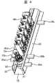
図4は試験管ホルダーと試験管ラックが同じベルトライン上に乗っている状態の斜視図。
図5は搬送路の上面図であり、代表的な停止パターンを示している。1 to 5 show an embodiment.
FIG. 1 is a perspective view of a test tube holder and an adapter alone.
FIG. 2 is a perspective view when the test tube is mounted.
FIG. 3 is a side sectional view of the test tube holder.
FIG. 4 is a perspective view showing a state in which the test tube holder and the test tube rack are on the same belt line.
FIG. 5 is a top view of the conveyance path and shows a typical stop pattern.
本実施形態における試験管ホルダー10は、帯電性及び導電性に優れた特殊な合成樹脂によって形成されたホルダー11,ホルダー12を有している。ホルダー11,ホルダー12の外形は円筒状の形であり、ホルダー11はベルトライン上での倒れ防止用のガイド部を有する必要があるため、上下で径が異なっており、ホルダー11の上部の径に対して下部の方が大きい径の形状になっている。 The
また、ホルダー11の内形は、例えば底がRになっている試験管を安定して設置できるようにする場合は11aのような形状になっているのが望ましい。 In addition, the inner shape of the
さらにホルダー11は11bのような溝形状部を設置している。これがあることにより例えばアダプタ13のような薄い板状の金属を弾性力のある形状に変形させ、円形状に一体形成した物を簡単に設置することが可能となる。 Further, the
ホルダー12は試験管60を収容するために、円筒中空の形状をしており、アダプタ13を邪魔しないよう縦方向に、アダプタ13a〜アダプタ13eが接する部分にホルダー12aの様なスリット状の形状部を設けている。 The
試験管を保持、支える役割のアダプタ13は、一定の長さの細い板状の弾性力のある形状をした複数の金属が、ある一定の間隔で連続して突出しており、アダプタ13fのように各板状の金属は底部では一体となっており、円形状に一体で形成されている。この連続に突出したアダプタ13a〜アダプタ13eを形成することにより試験管を保持する部分を実現している。 The
次に組み立て方法を説明する。アダプタ13の底部13fをホルダー11の溝形状部11bに嵌め込む。溝形状部11bはアダプタ13の板厚よりも幅を少し広くしてあるので容易に装着が可能である。 Next, the assembly method will be described. The
アダプタ13の取り付け後、ホルダー12をアダプタ13の上から被せるように装着する。これによりアダプタ13は完全に固定されることになる。 After the
最後にホルダー11とホルダー12の接合であるが、この場合は帯電性及び導電性を考慮すると、ホルダー11とホルダー12が密着している方がより効果的である。したがって、超音波溶着などの樹脂と樹脂が溶け合って接合させる方式が望ましい。超音波溶着法は一般的な接合法であり、広く普及している接合方法である。 Finally, the
もう一つの実施形態である試験管ホルダー10及び試験管ラック40が同じ搬送路を通過可能とするためには図4に示すような構造とすれば実現可能となる。これらの装置は制御部(図示なし)を有しており、制御部はCPU,メモリ,I/O等を有する情報処理装置で構成されている。 In order to allow the
搬送路はレール30にガイド31,32が取り付けまたは接合されており、試験管ホルダー10の大径部を上下方向でガイドする構造となっている。尚、レール30とガイド31,32は一体で形成された物でも良い。 In the conveyance path, guides 31 and 32 are attached or joined to the
さらに、搬送路上のベルトライン33がモータなどの駆動部によって動作することにより試験管ホルダー10は搬送される。 Furthermore, the
また、試験管ホルダー10の小径部を試験管ラック40と同等の幅にすることにより同じ搬送路で両者を搬送することが可能となる。ただし、形状及び大きさがまったく異なるため、動作を制御するためには両者を判別する必要がある。物体の有無及び形状を判別する方式としてはセンサーやカメラなど使用することが一般的である。 Further, by making the small diameter portion of the
比較的安価に試験管ホルダー10と試験管ラック40を判別する方法の例として、センサーを利用する方式を図5に示す。 As an example of a method for discriminating between the
各試験管ホルダー及び試験管ラックはある一定の間隔もしくは不一定な間隔を保った状態で、搬送路を稼動するベルトライン上に載った状態で搬送される。ベルトラインは状況に応じて停止することが可能であり、パルス制御のモータなどを使用すれば簡単にベルトラインのスピードコントロールも可能である。通常は連続運転である。 Each test tube holder and test tube rack are transported in a state of being placed on a belt line that operates the transport path at a certain interval or a non-constant interval. The belt line can be stopped depending on the situation, and the speed of the belt line can be easily controlled by using a pulse control motor or the like. Usually it is continuous operation.
また、センサーの検知(ON⇔OFF)によって動作を制御することができる一時停止機構34a,34bを具備すれば、一時停止機構34a〜34fを前後に動作させることにより、稼動中のベルトライン上の試験管ホルダー10あるいは試験管ラック40を停止制御が可能となる。尚、一時停止機構はソレノイドバルブなどを利用し、コンパクトで安価な機構構成となっている。 Moreover, if the
さらに、停止した移動体を判別するにはセンサー35a〜35dのようにセンサーを設置する構成にすることによって両者の判別は実現可能となる。本実施例で使用するセンサー方式はいろいろな方式が存在する中、安価な反射形のマイクロフォトセンサー方式を選択している。 Furthermore, in order to discriminate the moving body that has stopped, it is possible to discriminate both by using a configuration in which sensors are installed like the
移動中の試験管ホルダー10及び試験管ラック40を判別する必要がある場合には、少なくても形を認識できるカメラ方式などを使用するのが一般的であろう。 When it is necessary to discriminate between the moving
図5(1)は停止位置に試験管ホルダー10aをベルトライン上で停止させた例である。この時、センサー35aは試験管ホルダー10aを検知した状態となるのでONの信号を出力、センサー35bの位置には何も存在しない空間となるので検知してない状態でOFFの信号となる。これらにより停止した移動体は試験管ホルダー10であることが認識されることになる。次に、必要な場合は一時停止機構34bをベルトライン上に前進させることにより、次に搬送されてくる移動体も停止可能な状態とすることができる。同様な方法でセンサー35c,35dを利用して停止した移動体の種類の判別が可能である。 FIG. 5A shows an example in which the
図5(2)は試験管ホルダー10を停止中に試験管ラック40aが搬送されてきた場合の例である。試験管ラックは長方形の立方体の形状をしている。したがって、試験管ラックが到着するとセンサー35c,35dは両方とも検知はONの信号を出力する。即ち、システムは試験管ホルダー10の次にある移動体は試験管ラック40aであることを認識する。 FIG. 5B shows an example in which the
図5(3),(4)は停止位置に試験管ラック40aをベルトライン上で停止させた例である。この時、センサー35a〜35dは全て検知した状態となるのでONの信号を出力する。これにより停止した移動体は試験管ラック40aであることが認識できる。次に、必要な場合は一時停止機構34dをベルトライン上に前進させることにより、次に搬送されてくる移動体も停止可能な状態とすることができる。この場合の一時停止機構34bは試験管ラック40aが前方に存在するため、動作はしない制御とする。 5 (3) and 5 (4) are examples in which the
つまり、停止位置に搬送されてくる移動体の種類を判別し、動作させる一時停止機構を制御することが可能である。 That is, it is possible to determine the type of the moving body conveyed to the stop position and control the temporary stop mechanism to be operated.
さらに、これらセンサー35の取り付け位置に高さを変更してセンサー35を追加することにより、試験管ホルダー10に搭載された試験管60を検知することも可能である。これにより、停止した試験管ホルダーに試験管60が搭載されているかどうか認識することができる。 Furthermore, it is also possible to detect the
上記の実施例の発展型として、試験管ホルダー10及び試験管ラック40に情報送受信用タグ等を具備し、またシステム側に情報送受信機を具備することにより、搬送容器自身に搬送先の指定,搭載している検体入り試験管の仕分け方など、情報に基づいて制御することが可能となり、より便利で使いやすいシステムを構築することが可能となる。 As a developed version of the above embodiment, the
10 試験管ホルダー本体
11 ホルダー1
12 ホルダー2
13 アダプタ
30 レール
31 ガイド1
32 ガイド2
33 ベルトライン
34 一時停止機構
35 反射センサー
40 試験管ラック10 Test
12
13
32
33 Belt line 34 Pause mechanism 35
Claims (12)
Translated fromJapanese前記検体容器保持具は、
a)検体容器を収納する収納部を備えた円筒状のホルダー部と、
b)該ホルダー部を支持する円筒状の台座部と、
c)該ホルダー部に備えられたC字形の底部からほぼ垂直に延伸し、検体容器を保持する複数の延伸部を有し、該延伸部は中心に向かって屈曲しているアダプタと、を有し、
前記ラックは前記検体容器保持具のホルダー部の外形と略同じ幅を有し、
前記搬送路は、当該搬送路の両側に前記幅と略同じだけ離間したガイド部を有することを特徴とする検体搬送システム。
A transport path capable of transporting botha sample containerholder capable of holding asingle sample container for storing a sample anda rack capable of holding aplurality of sample containers,
The specimen container holderis
acylindrical holder portion having a housing part for housing the a)search body vessel,
b) acylindrical pedestal for supporting the holder;
c)substantially vertically extending from thebottom of theC-shaped provided in theholder, has a plurality of elongated portions forholding the specimen container,have a, and the adapter the stretching portion is bent toward the centerAnd
The rack has substantially the same width as the outer shape of the holder portion of the specimen container holder,
The sample transport system, wherein the transport path has guide portions that are spaced apart from each other by approximately the same width as the width on both sides of the transport path .
前記搬送路に、前記検体容器保持具,ラックのいずれが搬送されているかを識別する識別機構を備えたことを特徴とする検体搬送システム。
The sample transport system according to claim 1,
Specimen transport system comprising the identifying identification mechanism inthe transport path, the sample container holder, either the rack is conveyed.
前記識別機構の識別結果に基づいて、前記搬送路の動作を制御する制御機構を備えたことを特徴とする検体搬送システム。
The specimen transport system according to claim 2,
A specimen transport system comprising a control mechanism for controlling the operation of the transport path based on the identification result of the identification mechanism.
前記制御機構は、前記検体容器保持具とラックを異なる位置に停止させるように制御することを特徴とする検体搬送システム。
The specimen transport system according to claim 3, wherein
The sample transport system, wherein the control mechanism controls the sample container holder and the rack to stop at different positions.
前記検体容器保持具および前記ラックを搬送路上で停止させる停止機構を備え、
前記制御機構は、前記識別機構の識別結果に基づいて前記停止機構を作動させるか否かの制御することを特徴とする検体搬送システム。
The specimen transport system according to claim4 , wherein
A stop mechanism for stopping the sample container holder and the rack on the transport path;
The specimen transport system, wherein the control mechanism controls whether or not to operate the stop mechanism based on the identification result of the identification mechanism .
前記台座部は樹脂製であることを特徴とする検体搬送システム。
The sample transport system according to claim 1,
The specimen transport system, wherein the pedestal is made of resin.
前記アダプタは金属製であることを特徴とする検体搬送システム。
The sample transport system according to claim 1,
The sample transport system, wherein the adapter is made of metal.
前記アダプタの延伸部は、延伸方向と平行に中折れし、該中折れ部が中心方向に向いていることを特徴とする検体搬送システム。
The sample transport system according to claim 1,
The extension part of the adapter is bent in parallel with the extension direction, and the bent part is oriented in the center direction.
前記ホルダー部は前記アダプタのC字形の底部が嵌合するための溝部を有することを特徴とする検体搬送システム。
The sample transport system according to claim 1,
The specimen transport system according to claim 1, wherein the holder part has a groove part for fitting a C-shaped bottom part of the adapter.
前記アダプタの延伸部の先端部は外側に屈曲していることを特徴とする検体搬送システム。
The sample transport system according to claim 1,
A sample transport system, wherein a distal end portion of the extending portion of the adapter is bent outward.
前記台座部の外径は前記ホルダー部の外径より大きいことを特徴とする検体搬送システム。
The sample transport system according to claim 1,
The specimen transport system, wherein an outer diameter of the pedestal part is larger than an outer diameter of the holder part.
前記ホルダー部と前記台座部は熱可塑性の樹脂で構成され、かつ樹脂を振動及び加圧することにより熔融して接合されていることを特徴とする検体搬送システム。The sample transport system according to claim 1,
The specimen transport system, wherein the holder part and the pedestal part are made of a thermoplastic resin and are melted and joined by vibration and pressurization of the resin.
Priority Applications (1)
| Application Number | Priority Date | Filing Date | Title |
|---|---|---|---|
| JP2009123679AJP5393255B2 (en) | 2009-05-22 | 2009-05-22 | Sample transport system |
Applications Claiming Priority (1)
| Application Number | Priority Date | Filing Date | Title |
|---|---|---|---|
| JP2009123679AJP5393255B2 (en) | 2009-05-22 | 2009-05-22 | Sample transport system |
Publications (2)
| Publication Number | Publication Date |
|---|---|
| JP2010271204A JP2010271204A (en) | 2010-12-02 |
| JP5393255B2true JP5393255B2 (en) | 2014-01-22 |
Family
ID=43419342
Family Applications (1)
| Application Number | Title | Priority Date | Filing Date |
|---|---|---|---|
| JP2009123679AActiveJP5393255B2 (en) | 2009-05-22 | 2009-05-22 | Sample transport system |
Country Status (1)
| Country | Link |
|---|---|
| JP (1) | JP5393255B2 (en) |
Cited By (1)
| Publication number | Priority date | Publication date | Assignee | Title |
|---|---|---|---|---|
| CN108885223A (en)* | 2016-03-29 | 2018-11-23 | 株式会社日立高新技术 | Sample inspection automation system |
Families Citing this family (37)
| Publication number | Priority date | Publication date | Assignee | Title |
|---|---|---|---|---|
| EP2589967A1 (en) | 2011-11-04 | 2013-05-08 | Roche Diagnostics GmbH | Laboratory sample distribution system and corresponding method of operation |
| CN106000509B (en)* | 2011-12-28 | 2018-06-22 | 株式会社日立高新技术 | Single physical container stent |
| CH706410A1 (en)* | 2012-04-16 | 2013-10-31 | Rpd Tool Ag | Device for extraction of analytes with grinding balls. |
| JP2014055827A (en)* | 2012-09-12 | 2014-03-27 | Hosokawa Micron Corp | Permeation speed measuring device, and sample holding tool used for the same |
| AU2013202778A1 (en)* | 2013-03-14 | 2014-10-02 | Gen-Probe Incorporated | Systems, methods, and apparatuses for performing automated reagent-based assays |
| JP6139232B2 (en)* | 2013-04-12 | 2017-05-31 | 株式会社日立製作所 | Test tube rack |
| EP2977765A1 (en)* | 2014-07-23 | 2016-01-27 | Roche Diagniostics GmbH | Sample container carrier, laboratory sample distribution system and laboratory automation system |
| EP2995958A1 (en) | 2014-09-15 | 2016-03-16 | Roche Diagniostics GmbH | Method of operating a laboratory sample distribution system, laboratory sample distribution system and laboratory automation system |
| CN107207123B (en)* | 2015-01-23 | 2019-08-30 | 康宁股份有限公司 | Equipment for holding and preserving glassware |
| EP3096146A1 (en) | 2015-05-22 | 2016-11-23 | Roche Diagniostics GmbH | Method of operating a laboratory sample distribution system, laboratory sample distribution system and laboratory automation system |
| EP3112874A1 (en) | 2015-07-02 | 2017-01-04 | Roche Diagnostics GmbH | Storage module, method of operating a laboratory automation system and laboratory automation system |
| EP3121603A1 (en) | 2015-07-22 | 2017-01-25 | Roche Diagnostics GmbH | Sample container carrier, laboratory sample distribution system and laboratory automation system |
| EP3211429A1 (en) | 2016-02-26 | 2017-08-30 | Roche Diagnostics GmbH | Transport device having a tiled driving surface |
| EP3211430A1 (en) | 2016-02-26 | 2017-08-30 | Roche Diagnostics GmbH | Transport device with base plate modules |
| EP3211428A1 (en) | 2016-02-26 | 2017-08-30 | Roche Diagnostics GmbH | Transport device unit for a laboratory sample distribution system |
| WO2017157689A1 (en)* | 2016-03-15 | 2017-09-21 | Unilever Plc | Puck for holding a product container |
| CN109196363A (en)* | 2016-06-03 | 2019-01-11 | 豪夫迈·罗氏有限公司 | Laboratory sample distribution system and laboratory automation system |
| EP3255519B1 (en) | 2016-06-09 | 2019-02-20 | Roche Diagniostics GmbH | Laboratory sample distribution system and method of operating a laboratory sample distribution system |
| JP6752350B2 (en) | 2016-08-04 | 2020-09-09 | エフ.ホフマン−ラ ロシュ アーゲーF. Hoffmann−La Roche Aktiengesellschaft | Laboratory sample distribution system and laboratory automation system |
| EP3355065B1 (en) | 2017-01-31 | 2021-08-18 | Roche Diagnostics GmbH | Laboratory sample distribution system and laboratory automation system |
| EP3357842B1 (en) | 2017-02-03 | 2022-03-23 | Roche Diagnostics GmbH | Laboratory automation system |
| EP3410123B1 (en) | 2017-06-02 | 2023-09-20 | Roche Diagnostics GmbH | Method of operating a laboratory sample distribution system, laboratory sample distribution system and laboratory automation system |
| EP3428653B1 (en) | 2017-07-13 | 2021-09-15 | Roche Diagnostics GmbH | Method of operating a laboratory sample distribution system, laboratory sample distribution system and laboratory automation system |
| FR3070609B1 (en)* | 2017-09-01 | 2019-09-13 | Sncf Mobilites | STORAGE MODULE OF A MICROGRAPHIC TEST |
| EP3456415B1 (en) | 2017-09-13 | 2021-10-20 | Roche Diagnostics GmbH | Sample container carrier, laboratory sample distribution system and laboratory automation system |
| EP3457144B1 (en) | 2017-09-13 | 2021-10-20 | Roche Diagnostics GmbH | Sample container carrier, laboratory sample distribution system and laboratory automation system |
| EP3537159B1 (en) | 2018-03-07 | 2022-08-31 | Roche Diagnostics GmbH | Method of operating a laboratory sample distribution system, laboratory sample distribution system and laboratory automation system |
| EP3540443B1 (en) | 2018-03-16 | 2023-08-30 | Roche Diagnostics GmbH | Laboratory system, laboratory sample distribution system and laboratory automation system |
| CN118164173A (en) | 2019-05-03 | 2024-06-11 | 简·探针公司 | Container transport system for an analysis system |
| EP4022319A1 (en)* | 2019-08-26 | 2022-07-06 | Gen-Probe Incorporated | Receptacle transport carriers |
| CN111470165B (en)* | 2020-05-19 | 2024-11-26 | 安图实验仪器(郑州)有限公司 | Test tube holder for test tube transport |
| EP3925911B1 (en) | 2020-06-19 | 2023-05-24 | Roche Diagnostics GmbH | Laboratory sample distribution system and corresponding method of operation |
| EP3940388B1 (en) | 2020-07-15 | 2024-04-10 | Roche Diagnostics GmbH | Laboratory sample distribution system and method for operating the same |
| CN111942731B (en)* | 2020-08-25 | 2024-10-01 | 郑州金域临床检验中心有限公司 | Mechanical quick batch transfer device and test tube transfer method for medical waste test tubes |
| EP4001923B1 (en) | 2020-11-23 | 2024-06-05 | Roche Diagnostics GmbH | Laboratory sample distribution system and laboratory automation system |
| US11747356B2 (en) | 2020-12-21 | 2023-09-05 | Roche Diagnostics Operations, Inc. | Support element for a modular transport plane, modular transport plane, and laboratory distribution system |
| JP7471037B2 (en)* | 2021-02-04 | 2024-04-19 | 株式会社日立製作所 | Tube transport rack |
Family Cites Families (20)
| Publication number | Priority date | Publication date | Assignee | Title |
|---|---|---|---|---|
| JPS599692Y2 (en)* | 1979-11-27 | 1984-03-27 | オムロン株式会社 | test tube storage rack |
| JPH0259467U (en)* | 1988-10-25 | 1990-05-01 | ||
| EP0414644A3 (en)* | 1989-08-25 | 1991-08-28 | Greiner Vibrograf Ag | Chain fashioned holding device having tubes for holding a tubular vessel each |
| JP3172839B2 (en)* | 1991-12-20 | 2001-06-04 | アークレイ株式会社 | Attachment for container holder |
| JPH0592733U (en)* | 1992-04-24 | 1993-12-17 | 株式会社ニッテク | Rack structure |
| JPH09208044A (en)* | 1996-02-01 | 1997-08-12 | Aloka Co Ltd | Specimen carriage system |
| JP3045965B2 (en)* | 1996-09-02 | 2000-05-29 | 下田機工株式会社 | Oil interceptor |
| JP3444760B2 (en)* | 1997-09-11 | 2003-09-08 | 株式会社日立製作所 | Sample transport system |
| US5897090A (en)* | 1997-11-13 | 1999-04-27 | Bayer Corporation | Puck for a sample tube |
| JPH11138912A (en)* | 1997-11-14 | 1999-05-25 | Nittec Co Ltd | Automatic specimen/container number printer |
| US6413780B1 (en)* | 1998-10-14 | 2002-07-02 | Abbott Laboratories | Structure and method for performing a determination of an item of interest in a sample |
| JP3059194U (en)* | 1998-11-19 | 1999-07-02 | シグマ精器株式会社 | Blood collection tube transport system |
| JP3096685B2 (en)* | 1999-03-05 | 2000-10-10 | 照明 伊藤 | Test tube holder |
| JP2002181835A (en)* | 2000-12-15 | 2002-06-26 | Hitachi Ltd | Sample processing system |
| FI114661B (en)* | 2001-04-03 | 2004-11-30 | Thermo Clinical Labsystems Oy | Tubes Scaffolding |
| JP3723531B2 (en)* | 2002-07-24 | 2005-12-07 | アロカ株式会社 | Sample transfer device |
| JP4056982B2 (en)* | 2004-03-17 | 2008-03-05 | 株式会社アイディエス | Test tube holder |
| FR2873447B1 (en)* | 2004-07-23 | 2007-09-28 | Alain Michel Rousseau | MULTI-DISCIPLINARY AUTOMATIC ANALYZER FOR IN VITRO DIAGNOSIS |
| JP4332513B2 (en)* | 2005-03-31 | 2009-09-16 | 株式会社アイディエス | Test tube holder |
| CN101688874A (en)* | 2007-07-12 | 2010-03-31 | 希森美康株式会社 | Specimen container |
- 2009
- 2009-05-22JPJP2009123679Apatent/JP5393255B2/enactiveActive
Cited By (1)
| Publication number | Priority date | Publication date | Assignee | Title |
|---|---|---|---|---|
| CN108885223A (en)* | 2016-03-29 | 2018-11-23 | 株式会社日立高新技术 | Sample inspection automation system |
Also Published As
| Publication number | Publication date |
|---|---|
| JP2010271204A (en) | 2010-12-02 |
Similar Documents
| Publication | Publication Date | Title |
|---|---|---|
| JP5393255B2 (en) | Sample transport system | |
| JP3880658B2 (en) | Sample rack and apparatus and method for moving the same | |
| JP3880659B2 (en) | Transfer device and analyzer using the same | |
| JP2899535B2 (en) | Sample container holder and holder transporter | |
| US9851369B2 (en) | Storage and supply for vessel holders | |
| JP5511834B2 (en) | Sample transport system | |
| US5298425A (en) | Device for the positionally correct feeding of test strips to an analysis unit | |
| EP2589968A1 (en) | Laboratory sample distribution system, laboratory system and method of operating | |
| US8394344B2 (en) | Vial presence indicator for vial-bearing rack | |
| WO2014192712A1 (en) | Gripping mechanism | |
| JPH09101314A5 (en) | ||
| WO2019075704A1 (en) | Sample analysis system, and sample analysis system control method | |
| JPH0933540A5 (en) | ||
| US20140326082A1 (en) | Sample processing system | |
| EP3412603B1 (en) | Switch for a conveying line for transporting a laboratory diagnostic vessel carrier | |
| US11255867B2 (en) | Holder conveying device | |
| WO2012165595A1 (en) | Automatic analytical device | |
| US20110150724A1 (en) | Device for Gripping a Reaction Cuvette | |
| CN110809719A (en) | Unit for inserting or accommodating specimen container and specimen inspection automation system including the same | |
| JP2006292696A (en) | Sample rack and sample rack adapter | |
| JP5860615B2 (en) | Automatic analyzer | |
| JPH0910605A (en) | Test tube supporting rack | |
| JP2006052995A (en) | Sample container rotating device | |
| JP5996166B2 (en) | Automatic analyzer | |
| CN109765393A (en) | Consumable box positioning blanking mechanism and chemiluminescence detector |
Legal Events
| Date | Code | Title | Description |
|---|---|---|---|
| A621 | Written request for application examination | Free format text:JAPANESE INTERMEDIATE CODE: A621 Effective date:20120209 | |
| A521 | Written amendment | Free format text:JAPANESE INTERMEDIATE CODE: A523 Effective date:20120209 | |
| A977 | Report on retrieval | Free format text:JAPANESE INTERMEDIATE CODE: A971007 Effective date:20121214 | |
| A131 | Notification of reasons for refusal | Free format text:JAPANESE INTERMEDIATE CODE: A131 Effective date:20121218 | |
| A521 | Written amendment | Free format text:JAPANESE INTERMEDIATE CODE: A523 Effective date:20130215 | |
| TRDD | Decision of grant or rejection written | ||
| A01 | Written decision to grant a patent or to grant a registration (utility model) | Free format text:JAPANESE INTERMEDIATE CODE: A01 Effective date:20130917 | |
| A61 | First payment of annual fees (during grant procedure) | Free format text:JAPANESE INTERMEDIATE CODE: A61 Effective date:20131015 | |
| R150 | Certificate of patent or registration of utility model | Ref document number:5393255 Country of ref document:JP Free format text:JAPANESE INTERMEDIATE CODE: R150 Free format text:JAPANESE INTERMEDIATE CODE: R150 | |
| S531 | Written request for registration of change of domicile | Free format text:JAPANESE INTERMEDIATE CODE: R313531 | |
| S533 | Written request for registration of change of name | Free format text:JAPANESE INTERMEDIATE CODE: R313533 | |
| R350 | Written notification of registration of transfer | Free format text:JAPANESE INTERMEDIATE CODE: R350 |