JP5389570B2 - Multi-way selector valve - Google Patents
Multi-way selector valveDownload PDFInfo
- Publication number
- JP5389570B2 JP5389570B2JP2009194390AJP2009194390AJP5389570B2JP 5389570 B2JP5389570 B2JP 5389570B2JP 2009194390 AJP2009194390 AJP 2009194390AJP 2009194390 AJP2009194390 AJP 2009194390AJP 5389570 B2JP5389570 B2JP 5389570B2
- Authority
- JP
- Japan
- Prior art keywords
- outlet
- valve
- inlet
- pressure
- valve body
- Prior art date
- Legal status (The legal status is an assumption and is not a legal conclusion. Google has not performed a legal analysis and makes no representation as to the accuracy of the status listed.)
- Active
Links
- 239000003507refrigerantSubstances0.000claimsdescription43
- 230000007704transitionEffects0.000claimsdescription10
- 239000012530fluidSubstances0.000claimsdescription7
- 238000010619multiway switchingMethods0.000claimsdescription7
- 235000003642hungerNutrition0.000claimsdescription2
- 230000037351starvationEffects0.000claimsdescription2
- 239000007788liquidSubstances0.000description9
- 238000005057refrigerationMethods0.000description9
- 238000001816coolingMethods0.000description5
- 238000010438heat treatmentMethods0.000description5
- 230000002093peripheral effectEffects0.000description4
- 238000003780insertionMethods0.000description3
- 230000037431insertionEffects0.000description3
- 239000003566sealing materialSubstances0.000description2
- 230000001052transient effectEffects0.000description2
- 240000007594Oryza sativaSpecies0.000description1
- 235000007164Oryza sativaNutrition0.000description1
- 230000002159abnormal effectEffects0.000description1
- 230000005856abnormalityEffects0.000description1
- 230000002411adverseEffects0.000description1
- 238000010586diagramMethods0.000description1
- 230000000694effectsEffects0.000description1
- 235000009566riceNutrition0.000description1
- 238000007789sealingMethods0.000description1
- 239000007787solidSubstances0.000description1
Images


Classifications
- F—MECHANICAL ENGINEERING; LIGHTING; HEATING; WEAPONS; BLASTING
- F16—ENGINEERING ELEMENTS AND UNITS; GENERAL MEASURES FOR PRODUCING AND MAINTAINING EFFECTIVE FUNCTIONING OF MACHINES OR INSTALLATIONS; THERMAL INSULATION IN GENERAL
- F16K—VALVES; TAPS; COCKS; ACTUATING-FLOATS; DEVICES FOR VENTING OR AERATING
- F16K31/00—Actuating devices; Operating means; Releasing devices
- F16K31/02—Actuating devices; Operating means; Releasing devices electric; magnetic
- F16K31/04—Actuating devices; Operating means; Releasing devices electric; magnetic using a motor
- F—MECHANICAL ENGINEERING; LIGHTING; HEATING; WEAPONS; BLASTING
- F15—FLUID-PRESSURE ACTUATORS; HYDRAULICS OR PNEUMATICS IN GENERAL
- F15B—SYSTEMS ACTING BY MEANS OF FLUIDS IN GENERAL; FLUID-PRESSURE ACTUATORS, e.g. SERVOMOTORS; DETAILS OF FLUID-PRESSURE SYSTEMS, NOT OTHERWISE PROVIDED FOR
- F15B13/00—Details of servomotor systems ; Valves for servomotor systems
- F15B13/02—Fluid distribution or supply devices characterised by their adaptation to the control of servomotors
- F—MECHANICAL ENGINEERING; LIGHTING; HEATING; WEAPONS; BLASTING
- F16—ENGINEERING ELEMENTS AND UNITS; GENERAL MEASURES FOR PRODUCING AND MAINTAINING EFFECTIVE FUNCTIONING OF MACHINES OR INSTALLATIONS; THERMAL INSULATION IN GENERAL
- F16K—VALVES; TAPS; COCKS; ACTUATING-FLOATS; DEVICES FOR VENTING OR AERATING
- F16K11/00—Multiple-way valves, e.g. mixing valves; Pipe fittings incorporating such valves
- F16K11/02—Multiple-way valves, e.g. mixing valves; Pipe fittings incorporating such valves with all movable sealing faces moving as one unit
- F16K11/06—Multiple-way valves, e.g. mixing valves; Pipe fittings incorporating such valves with all movable sealing faces moving as one unit comprising only sliding valves, i.e. sliding closure elements
- F16K11/072—Multiple-way valves, e.g. mixing valves; Pipe fittings incorporating such valves with all movable sealing faces moving as one unit comprising only sliding valves, i.e. sliding closure elements with pivoted closure members
- F16K11/074—Multiple-way valves, e.g. mixing valves; Pipe fittings incorporating such valves with all movable sealing faces moving as one unit comprising only sliding valves, i.e. sliding closure elements with pivoted closure members with flat sealing faces
- F—MECHANICAL ENGINEERING; LIGHTING; HEATING; WEAPONS; BLASTING
- F16—ENGINEERING ELEMENTS AND UNITS; GENERAL MEASURES FOR PRODUCING AND MAINTAINING EFFECTIVE FUNCTIONING OF MACHINES OR INSTALLATIONS; THERMAL INSULATION IN GENERAL
- F16K—VALVES; TAPS; COCKS; ACTUATING-FLOATS; DEVICES FOR VENTING OR AERATING
- F16K31/00—Actuating devices; Operating means; Releasing devices
- F16K31/02—Actuating devices; Operating means; Releasing devices electric; magnetic
- F16K31/04—Actuating devices; Operating means; Releasing devices electric; magnetic using a motor
- F16K31/041—Actuating devices; Operating means; Releasing devices electric; magnetic using a motor for rotating valves
- F—MECHANICAL ENGINEERING; LIGHTING; HEATING; WEAPONS; BLASTING
- F16—ENGINEERING ELEMENTS AND UNITS; GENERAL MEASURES FOR PRODUCING AND MAINTAINING EFFECTIVE FUNCTIONING OF MACHINES OR INSTALLATIONS; THERMAL INSULATION IN GENERAL
- F16K—VALVES; TAPS; COCKS; ACTUATING-FLOATS; DEVICES FOR VENTING OR AERATING
- F16K35/00—Means to prevent accidental or unauthorised actuation
- F—MECHANICAL ENGINEERING; LIGHTING; HEATING; WEAPONS; BLASTING
- F25—REFRIGERATION OR COOLING; COMBINED HEATING AND REFRIGERATION SYSTEMS; HEAT PUMP SYSTEMS; MANUFACTURE OR STORAGE OF ICE; LIQUEFACTION SOLIDIFICATION OF GASES
- F25B—REFRIGERATION MACHINES, PLANTS OR SYSTEMS; COMBINED HEATING AND REFRIGERATION SYSTEMS; HEAT PUMP SYSTEMS
- F25B41/00—Fluid-circulation arrangements
- F25B41/20—Disposition of valves, e.g. of on-off valves or flow control valves
- Y—GENERAL TAGGING OF NEW TECHNOLOGICAL DEVELOPMENTS; GENERAL TAGGING OF CROSS-SECTIONAL TECHNOLOGIES SPANNING OVER SEVERAL SECTIONS OF THE IPC; TECHNICAL SUBJECTS COVERED BY FORMER USPC CROSS-REFERENCE ART COLLECTIONS [XRACs] AND DIGESTS
- Y10—TECHNICAL SUBJECTS COVERED BY FORMER USPC
- Y10T—TECHNICAL SUBJECTS COVERED BY FORMER US CLASSIFICATION
- Y10T137/00—Fluid handling
- Y10T137/8593—Systems
- Y10T137/86493—Multi-way valve unit
- Y10T137/86839—Four port reversing valves
- Y—GENERAL TAGGING OF NEW TECHNOLOGICAL DEVELOPMENTS; GENERAL TAGGING OF CROSS-SECTIONAL TECHNOLOGIES SPANNING OVER SEVERAL SECTIONS OF THE IPC; TECHNICAL SUBJECTS COVERED BY FORMER USPC CROSS-REFERENCE ART COLLECTIONS [XRACs] AND DIGESTS
- Y10—TECHNICAL SUBJECTS COVERED BY FORMER USPC
- Y10T—TECHNICAL SUBJECTS COVERED BY FORMER US CLASSIFICATION
- Y10T137/00—Fluid handling
- Y10T137/8593—Systems
- Y10T137/86493—Multi-way valve unit
- Y10T137/86863—Rotary valve unit
Landscapes
- Engineering & Computer Science (AREA)
- General Engineering & Computer Science (AREA)
- Mechanical Engineering (AREA)
- Physics & Mathematics (AREA)
- Fluid Mechanics (AREA)
- Thermal Sciences (AREA)
- Multiple-Way Valves (AREA)
- Electrically Driven Valve-Operating Means (AREA)
Description
Translated fromJapanese本発明は、冷凍サイクル等に用いられる三方切換弁や四方切換弁等の多方切換弁に係り、特に、流路の切り換えを、ロータとステータからなるモーター等のアクチュエータで弁体を回動させることにより行うロータリ式の多方切換弁に関する。The present invention relates to a multi-way switching valve such as a three-way switching valve or a four-way switching valve used for a refrigeration cycle, and in particular, the flow path is switched by an actuator such as a motor composed of a rotor and a stator. The present invention relates to a rotarymulti-way switching valve performed by
一般に、空気調和機、冷凍装置等の冷凍サイクルは、圧縮機、気液分離器、凝縮器(室外熱交換器)、蒸発器(室内熱交換器)、及び膨張弁等に加えて、流路(流れ方向)切換手段としての四方切換弁を備えている。 In general, a refrigeration cycle such as an air conditioner or a refrigeration apparatus includes a flow path in addition to a compressor, a gas-liquid separator, a condenser (outdoor heat exchanger), an evaporator (indoor heat exchanger), an expansion valve, and the like. (Flow direction) A four-way switching valve is provided as switching means.
この四方切換弁を備えた冷凍サイクルの一例を図5、図6を参照しながら説明する。図示例の冷凍サイクル300は、空気調和機のもので、運転モード(冷房運転と暖房運転)の切り換えを四方切換弁320で行うようになっている。すなわち、圧縮機310、気液分離器312、凝縮器(室外熱交換器)314、蒸発器(室内熱交換器)316、及び膨張弁318を備え、前記の圧縮機310、気液分離器312、凝縮器314、及び蒸発器316の四者の間に、第1〜第4の4つのポート(入出口)a、b、c、d(図6参照)を有する四方切換弁320が配在されている。 An example of the refrigeration cycle provided with this four-way switching valve will be described with reference to FIGS. The
前記各機器類間は導管(パイプ)等で形成される流路で接続されている。具体的には、気液分離器312内の冷媒を圧縮機310に導く吸入流路321、圧縮機310から吐出された高圧冷媒を四方切換弁320の第1ポートaに導く吐出流路322、四方切換弁320の第2ポートbと凝縮器314の第1流通口314aとを接続する凝縮器側送り戻し流路323、四方切換弁320の第3ポートcと蒸発器316の第1流通口316aとを接続する蒸発器側送り戻し流路324、四方切換弁320の第4ポートdと気液分離器312の戻し口312aとを接続する戻し流路325、凝縮器314の第2流通口314bと膨張弁318とを接続する流路326と、及び、膨張弁318と蒸発器316の第2流通口316bとを接続する流路327が設けられている。 The devices are connected by a flow path formed by a conduit (pipe) or the like. Specifically, a
このような構成の冷凍サイクル300においては、冷房運転モードが選択されたときには、四方切換弁320が、図6(A)に示される如くに、吐出流路322と凝縮器側送り戻し流路323とを連通させるとともに、蒸発器側送り戻し流路324と戻し流路325とを連通させる状態に切り換えられる。このときには、図5において実線矢印で示される如くに、気液分離器312内の低圧冷媒が吸入流路321を介して圧縮機310に吸入されるとともに、圧縮機310の吐出口310aから高温高圧の冷媒が吐出流路322、四方切換弁320、及び凝縮器側送り戻し流路323を介して凝縮器314に導かれ、凝縮器314において室外空気と熱交換して凝縮し、高圧の二相冷媒となって流路326を介して膨張弁318に導入される。この膨張弁318により高圧の冷媒が減圧され、減圧された低圧の冷媒は、流路327を介して蒸発器316に導入され、ここで室内空気と熱交換(冷房)して蒸発し、蒸発器316からは低温低圧の冷媒が蒸発器側送り戻し流路324、四方切換弁320、及び戻し流路325を介して気液分離器312に戻される。 In the
それに対し、暖房運転モードが選択されたときには、四方切換弁320が、図6(B)に示される如くに、吐出流路322と蒸発器側送り戻し流路324とを連通させるとともに、凝縮器側送り戻し流路323と戻し流路325とを連通させる状態に切り換えられる。このときには、図5において破線矢印で示される如くに、気液分離器312内の冷媒が吸入流路321を介して圧縮機310に吸入されるとともに、圧縮機310の吐出口310aから高温高圧の冷媒が吐出流路322、四方切換弁320、及び蒸発器側送り戻し流路324を介して蒸発器316に導かれ、蒸発器316において室内空気と熱交換(暖房)して蒸発し、高圧の二相冷媒となって流路327を介して膨張弁318に導入される。この膨張弁318により高圧の冷媒が減圧され、減圧された低圧の冷媒は、流路326を介して凝縮器314に導入され、ここで室外空気と熱交換して凝縮し、凝縮器314からは低温低圧の冷媒が凝縮器側送り戻し流路323、四方切換弁320、及び戻し流路325を介して気液分離器312に戻される。 On the other hand, when the heating operation mode is selected, the four-
前記した如くの冷凍サイクルに組み込まれるロータリ式の四方切換弁は、下記特許文献1にも見られるように、基本的には、モータ等のアクチュエータにより回動せしめられる弁体と、該弁体を回動可能に保持する、弁シート部及び弁室が設けられた弁本体とを備え、この弁本体の弁シート部に、第1入出口(凝縮器連通口)及び第2入出口(蒸発器連通口)、並びに、圧縮機吐出側からの高圧冷媒を前記弁室に導入するための高圧入口及び圧縮機吸入側へ低圧冷媒を導出するための低圧出口が設けられ、前記弁体を回動させることによって、前記弁体内に設けられた通路部により前記第1入出口及び第2入出口のいずれかと前記高圧入口(弁室)及び低圧出口のいずれかとを選択的に連通させることにより、流路の切り換えを行うようになっている。 The rotary type four-way switching valve incorporated in the refrigeration cycle as described above basically includes a valve body rotated by an actuator such as a motor, and the valve body as seen in Patent Document 1 below. And a valve main body provided with a valve seat portion and a valve chamber, which are rotatably held, and a first inlet / outlet (condenser communication port) and a second inlet / outlet (evaporator) in the valve seat portion of the valve main body. A communication port), a high-pressure inlet for introducing high-pressure refrigerant from the compressor discharge side into the valve chamber, and a low-pressure outlet for deriving low-pressure refrigerant to the compressor suction side. By allowing the passage portion provided in the valve body to selectively communicate either the first inlet / outlet or the second inlet / outlet with either the high-pressure inlet (valve chamber) or the low-pressure outlet. The road is switched.
しかしながら、前記した如くの従来のロータリ式四方切換弁は、弁室に高圧冷媒を導入するとともに、弁体内の通路部に低圧冷媒を流すようになっているので、弁体の内外の差圧が極めて大きくなり、その差圧(高圧冷媒)により弁体が弁シート部に強く押し付けられ、そのため、流路切換時に弁体がスムーズに回動せず、流路切換動作が重くなる嫌いがあり、また、弁体や弁シート部が摩耗しやすいといった問題があった。 However, the conventional rotary four-way switching valve as described above introduces high-pressure refrigerant into the valve chamber and allows low-pressure refrigerant to flow through the passage in the valve body. The valve body is strongly pressed against the valve seat by the differential pressure (high-pressure refrigerant), and therefore the valve body does not rotate smoothly when switching the flow path, and there is a dislike that the flow path switching operation becomes heavy, Further, there is a problem that the valve body and the valve seat portion are easily worn.
このような問題を解消すべく、本発明の発明者等は、先に、次のような構成の四方切換弁を提案している(下記特許文献2)。 In order to solve such a problem, the inventors of the present invention have previously proposed a four-way switching valve having the following configuration (Patent Document 2 below).
すなわち、該提案の四方切換弁1’は、図3、図4に示される如くに、流路を切り換えるべくモータ等のアクチュエータ15により回動せしめられる弁体50と、この弁体50を回動可能に保持する弁本体60とを備え、前記弁体50内に高圧冷媒が導入される高圧通路部55が形成され、前記弁本体60に、前記高圧通路部55の出口側に選択的に連通せしめられる第1入出口13及び第2入出口14が設けられた弁シート部65と前記第1入出口13及び第2入出口14を介して選択的に低圧冷媒が導入される弁室61とが設けられ、流路切換時に、前記弁体50における前記高圧通路部55の出口側端部が前記弁シート部65における前記第1入出口13と第2入出口14との間を摺動するようにされ、前記高圧冷媒による前記弁体50を前記弁シート部65に押し付ける方向の力が略キャンセルされるように、前記弁体50等の寸法形状(具体的には、逆L形軸部53の下端部54の外径や角形リング75の実効内径)が設定されてなる。Specifically, as shown in FIGS. 3 and 4, the proposed four-way switching valve 1 ′ includes a
より詳しくは、前記弁体50は、逆L形軸部53を有し、該逆L形軸部53内に、高圧冷媒を前記第1入出口13及び第2入出口14に選択的に導くための逆L形ないしクランク状の前記高圧通路部55が形成されている。また、前記弁室61における前記弁シート部65とは反対側の底部に前記弁体50の高圧通路部55に高圧流体を導くための高圧入口11が設けられ、さらに、前記弁室61に開口する低圧出口12が設けられて、前記冷凍サイクルで用いられる四方切換弁として機能するようにされている。 More specifically, the
かかる提案の四方切換弁1’では、弁体50内に高圧冷媒が導入される高圧通路部55が形成されるとともに、弁室61には低圧冷媒が導入されるようになっていて、高圧冷媒による弁体50を弁シート部65に押し付ける方向の力が略キャンセルされるように、弁体50等の寸法形状が設定されているので、流路切換動作を容易に軽やかに行うことができるとともに、弁体50や弁シート部65が摩耗しにくくなり、その結果、耐久性、信頼性が向上する。 In the proposed four-way switching valve 1 ′, a high-
しかしながら、前記した如くの従来のロータリ式四方切換弁1’では、弁体50を図4(A)に示される位置(以下、第1の運転位置)から図4(D)に示される位置(以下、第2の運転位置)へ回動させること、及び、その逆方向に回動させることにより、流路の切り換え、言い換えれば、第1入出口13と高圧通路部55とを連通させるとともに、第2入出口14と低圧出口12とを連通させる例えば冷房運転状態と、第2入出口14と高圧通路部55とを連通させるとともに、第1入出口13と低圧出口12とを連通させる例えば暖房運転状態との切り換え行われる。 However, in the conventional rotary type four-way switching valve 1 ′ as described above, the
この場合、流路切換過渡時(第1の運転位置から第2の運転位置への、及び、第2の運転位置から第1の運転位置への切換途中)には、図4(B)、(C)に示される如くに、弁体50における高圧通路部55の出口側端部55a(角形リング75)が弁シート部65における第1入出口13と第2入出口14との間の部分に押し付けられた状態で摺動するので、高圧通路部55の出口側が弁シート部65によって閉止されてしまう。 In this case, at the time of flow path switching transient (from the first operating position to the second operating position and in the middle of switching from the second operating position to the first operating position), FIG. As shown in (C), the outlet
このように、流路切換過渡時に高圧通路部55の出口側が閉止されてしまうと、極短時間であるとはいえ、圧縮機吐出側の高圧冷媒に逃げ場がなくなり、高圧冷媒の圧力が急上昇して、流路切換動作に支障を来したり、フェールセーフ機構により装置に異常・故障が発生したと誤判断されて装置が無闇に停止してしまう等の問題が生じるおそれがある。 In this way, if the outlet side of the high-
本発明は、かかる事情に鑑みてなされたもので、その目的とするところは、流路切換過渡時に、高圧冷媒の圧力が過度に上昇することを抑えることができて、流路切換動作に支障を来すことがないようにされるとともに、フェールセーフ機構により装置に異常・故障が発生したと誤判断されて装置が無闇に停止してしまうような事態を招くことがないようにできる多方切換弁を提供することにある。 The present invention has been made in view of such circumstances, and an object of the present invention is to prevent an excessive increase in the pressure of the high-pressure refrigerant at the time of the flow path switching transient, which hinders the flow path switching operation. Multi-way switching that prevents the device from being erroneously judged to have malfunctioned or failed due to a fail-safe mechanism and causing the device to stop silently To provide a valve.
前記目的を達成すべく、本発明に係る四方切換弁は、基本的には、流路を切り換えるべくアクチュエータにより回動せしめられる弁体と、該弁体を回動可能に保持する弁本体とを備え、前記弁体内に高圧流体が導入される高圧通路部が形成され、前記弁本体に、前記高圧通路部の出口側に選択的に連通せしめられる第1入出口及び第2入出口が設けられた弁シート部と前記第1入出口及び第2入出口を介して選択的に低圧流体が導入される弁室とが設けられ、流路切換過渡時に、前記弁体における高圧通路部の出口側端部が前記弁シート部における第1入出口と第2入出口との間の部分に押し付けられた状態で摺動するようにされ、前記弁シート部に、流路切換過渡時において、前記高圧通路部の高圧冷媒を前記弁室側に逃がすための逃がし通路部が前記第1入出口と第2入出口との間に形成されるとともに、前記逃がし通路部は、流路切換過渡時に前記高圧通路部の出口側端部と部分的に重なり合うことを特徴としている。To achieve the above object, the four-way selector valve according to the present invention is basically, a valve body is caused to rotate by the baseKua actuator for switching the flow path, the valve body to hold the valve member rotatably A high-pressure passage portion into which a high-pressure fluid is introduced is formed in the valve body, and a first inlet / outlet and a second inlet / outlet that are selectively communicated with the valve body on the outlet side of the high-pressure passage portion. A valve seat portion provided and a valve chamber into which low-pressure fluid is selectively introduced via the first inlet / outlet and the second inlet / outlet are provided. The outlet side end is made to slide in a state of being pressed against a portion between the first inlet and outlet and the second inlet and outlet in the valve seat portion, and the valve seat portion is in a flow path switching transition state.escape starvation passagefor releasing the high pressure refrigerant of the high-pressure passage portion to said valve chamber sideSerial first inlet and outlet and is formedbetween the second inlet and outletRutotomoni, the relief passage is characterized inthat overlap the outlet end partially of the high-pressure path section during flow path switching transients.
前記弁体は、好ましくは、逆L形軸部を有し、該逆L形軸部内に、高圧冷媒を前記第1入出口及び第2入出口に選択的に導くための逆L形ないしクランク状の前記高圧通路部が形成される。 The valve body preferably has an inverted L-shaped shaft portion, and an inverted L-shape or crank for selectively guiding the high-pressure refrigerant to the first inlet / outlet and the second inlet / outlet in the inverted L-shaped shaft portion. The high-pressure passage portion having a shape is formed.
他の好ましい態様では、前記弁室における前記アクチュエータ側に、前記第1入出口及び前記第2入出口が形成された弁シート部が設けられ、前記弁室における前記アクチュエータとは反対側の底部に前記弁体の高圧通路部に高圧流体を導くための高圧入口が形成される。 In another preferred embodiment, a valve seat portion in which the first inlet / outlet and the second inlet / outlet are formed is provided on the actuator side of the valve chamber, and the bottom of the valve chamber on the opposite side to the actuator. A high-pressure inlet for introducing a high-pressure fluid into the high-pressure passage portion of the valve body is formed.
別の好ましい態様では、前記弁室に開口する低圧出口が形成されて、四方切換弁として機能するように構成される。 In another preferred embodiment, a low-pressure outlet that opens to the valve chamber is formed, and is configured to function as a four-way switching valve.
本発明に係る多方切換弁では、弁シート部における第1入出口と第2入出口との間に、溝、切欠、透孔等からなる逃がし通路部が形成されていることから、流路切換過渡時においては、逃がし通路部と高圧通路部の出口側端部とが部分的に重なり合い、圧縮機吐出側の高圧冷媒は、高圧通路部から前記逃がし通路部を通じて弁室に逃がされる。そのため、流路切換過渡時に、高圧冷媒の圧力が過度に上昇することを抑えることができ、その結果、流路切換動作に支障を来すことがないようにされるとともに、フェールセーフ機構により装置に異常・故障が発生したと誤判断されて装置が無闇に停止してしまうような事態を招くことがないようにできる。 In the multi-way switching valve according to the present invention, a passage passage portion including a groove, a notch, a through hole, and the like is formed between the first inlet / outlet and the second inlet / outlet in the valve seat portion. During the transition, the escape passage portion and the outlet side end portion of the high-pressure passage portion partially overlap, and the high-pressure refrigerant on the compressor discharge side is released from the high-pressure passage portion to the valve chamber through the escape passage portion. Therefore, it is possible to suppress an excessive increase in the pressure of the high-pressure refrigerant at the time of the channel switching transition, and as a result, the channel switching operation is prevented from being hindered, and the apparatus is provided by the fail-safe mechanism. Therefore, it is possible to prevent a situation in which the apparatus is mistakenly determined to have been abnormal and failed and the apparatus will stop silently.
以下、本発明の四方切換弁の実施形態を図面を参照しながら説明する。
図1は、本発明に係る多方(四方)切換弁の一実施形態を示す縦断面図である。なお、本実施形態の四方切換弁1において、前述した図3に示される従来の四方切換弁1’の各部に対応する部分には同一の符号が付されている。Hereinafter, an embodiment of a four-way selector valve of the present invention will be described with reference to the drawings.
FIG. 1 is a longitudinal sectional view showing an embodiment of a multi-way (four-way) switching valve according to the present invention. In the four-way switching valve 1 of the present embodiment, the same reference numerals are given to portions corresponding to the respective parts of the conventional four-way switching valve 1 ′ shown in FIG.
図示例の四方切換弁1も、カーエアコン等の冷凍サイクルに用いられるもので、アクチュエータとしてのロータ16及びステータ17からなるモータ15により回動せしめられる弁体50と、この弁体50を回動可能に保持する弁本体60とを備えている。 The illustrated four-way selector valve 1 is also used in a refrigeration cycle such as a car air conditioner. The
本実施形態の四方切換弁1では、モータ15のロータ16と弁体50との間に、遊星歯車式減速機構40が介装されており、ロータ16の回転は相当減速されて弁体50に伝達されるようになっている。なお、遊星歯車式減速機構40の詳細構成は、必要なら、例えば本発明の出願人による特開2008-101765号公報等を参照されたい。 In the four-way switching valve 1 of the present embodiment, a planetary gear
前記弁本体60のモータ15側に位置する上側分割体60Aには、第1入出口13及び第2入出口14が適宜の角度間隔をあけて形成された弁シート部65が嵌合固定されるとともに、弁室61が形成されている。前記弁本体60における前記上側分割体60Aの下側に位置する下側分割体60Bにおける底部中央(回転軸線O上)には、高圧入口11が設けられている。前記上側分割体60Aには、前記第1入出口13に連なる、周側部に開口する第1接続口(継手)63aを持つ逆L形通路部63、前記第2入出口14に連なる、周側部に開口する第2接続口(継手)64aを持つ逆L形通路部64が形成されている。A
前記弁体50は、上から順に、前記モータ15内の遊星歯車式減速機構40に連結された小径軸部51、中央軸部52、及び逆L形軸部53からなり、逆L形軸部53内には、高圧入口11からの高圧冷媒を前記第1入出口13及び第2入出口14に選択的に導くための逆L形ないしクランク状の高圧通路部55が形成されている。高圧通路部55は、高圧入口11側の下側通路部55Aと弁シート部65側(第1入出口13及び第2入出口14側)の上側通路部55Bとからなり、上側通路部55Bの出口側端部55aにはシール材としてのOリング74、及び角形リング75(後述)が装着されている。The
前記弁体50の小径軸部51はモータ15側に設けられた厚肉円筒状のガイド部49に回動自在に嵌挿され、前記中央軸部52は、前記上側分割体60A及び弁シート部65の中央(回転軸線O上)に形成された挿通穴66、67に回動自在に嵌挿され、前記逆L形軸部53の下端部は、底部中央の高圧入口11上に連設された挿通穴68に回動自在に挿入されている。The small-
また、前記高圧通路部55における弁シート部65側の端部55a(出口側の端部)の内周溝(凹部)には、シール部材としてOリング74と角形リング75が装着されている。ここでは、高圧通路部55の高圧冷媒によりOリング74が半径方向外方に押圧されて断面が円形から楕円状に変化するが、このOリング74の形状変化を利用して角形リング75の一端面を弁シート部65に押し付けてシール効果を得る構成となっている。さらに、弁シート部65と前記上側分割体60Aとの間にもシール部材としてのOリング(図示せず)が介装されている。In addition, an O-
さらに、本実施形態の四方切換弁1では、弁本体60の上下2カ所に、弁体50を摺動回転自在に支持するスリーブ状の軸受部材81、82が配設されるとともに、弁体50の縦辺部53Aと弁本体60の挿通穴68との間にシール材83が介装されている。 Furthermore, in the four-way switching valve 1 of the present embodiment, sleeve-shaped bearing members 81 and 82 that support the
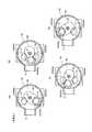
かかる構成の四方切換弁1においては、弁体50を図2(A)に示される位置(第1の運転位置)から図2(D)に示される位置(第2の運転位置)へ回動させること、及び、その逆方向に回動させることにより、流路の切り換え、言い換えれば、第1入出口13と高圧通路部55とを連通させるとともに、第2入出口14と低圧出口12とを連通させる例えば冷房運転状態と、第2入出口14と高圧通路部55とを連通させるとともに、第1入出口13と低圧出口12とを連通させる例えば暖房運転状態との切り換えが行われる。In the four-way switching valve 1 having such a configuration, the
この場合、流路切換過渡時(第1の運転位置から第2の運転位置への、及び、第2の運転位置から第1の運転位置への切換途中)には、図2(B)、(C)に示される如くに、弁体50における高圧通路部55の出口側端部55a(角形リング75)が弁シート部65における第1入出口13と第2入出口14との間の部分に押し付けられた状態で摺動する。 In this case, at the time of flow path switching transition (from the first operating position to the second operating position and during the switching from the second operating position to the first operating position), FIG. As shown in (C), the outlet
ここで、前述した図3、図4に示される従来の四方切換弁1’では、前記流路切換過渡時に高圧通路部55の出口側が弁シート部65によって閉止されてしまい、圧縮機吐出側の高圧冷媒に逃げ場がなくなり、高圧冷媒の圧力が急上昇して、流路切換動作に支障を来したり、フェールセーフ機構により装置に異常・故障が発生したと誤判断されて装置が無闇に停止してしまう等の問題が生じるおそれがあったが、本例の四方切換弁1では、前記問題を次のようにして解消している。 Here, in the conventional four-way switching valve 1 ′ shown in FIG. 3 and FIG. 4 described above, the outlet side of the high
すなわち、前記弁シート部65における前記第1入出口13と第2入出口14との間に、流路切換過渡時において、前記高圧通路部55の高圧冷媒を前記弁室61側に逃がすための溝穴からなる逃がし通路部69が形成されている。この逃がし通路部69は、前記高圧通路部55の出口側端部55aと部分的に重なり合うように、内周側と外周側とが同心の円弧で両端が半円の、平面視飯ごう形とされている。 That is, between the first inlet /
このように、弁シート部65における第1入出口13と第2入出口14との間に、溝穴からなる逃がし通路部69が形成されていることにより、流路切換過渡時においては、図2(B)、(C)に示される如くに、逃がし通路部69と高圧通路部55の出口側端部55aとが部分的に重なり合い、圧縮機吐出側の高圧冷媒は、高圧通路部55から前記逃がし通路部69を通じて弁室61に逃がされるので、流路切換過渡時に、高圧冷媒の圧力が過度に上昇することを抑えることができる。そのため、流路切換動作に支障を来すことがないようにされるとともに、フェールセーフ機構により装置に異常・故障が発生したと誤判断されて装置が無闇に停止してしまうような事態を招くことがないようにできる。 As described above, the
なお、高圧通路部55から弁室61に逃がされた冷媒は、低圧出口12等を通じて圧縮機吸入側に戻されるので、空調装置(カーエアコン)の運転に何ら悪影響を及ぼすことはない。また、弁体50が図2(A)に示される第1の運転位置にあるとき、及び、図2(D)に示される第2の運転位置にあるときには、逃がし通路部69と高圧通路部55の出口側端部55aとは全く重なり合うことはないので、高圧冷媒が弁室61に漏れ出ることはない。 Note that the refrigerant that has escaped from the high-
上記実施形態では、本発明を多方切換弁の一つである四方切換弁に適用した場合について説明したが、本発明は、四方切換弁の他、例えば前記低圧出口12を無くした三方切換弁等にも同様に適用できる。 In the above embodiment, the case where the present invention is applied to a four-way switching valve which is one of the multi-way switching valves has been described. However, the present invention is not limited to a four-way switching valve, for example, a three-way switching valve without the low-
1 四方切換弁
11 高圧入口
12 低圧出口
13 第1入出口
14 第2入出口
15 モータ(アクチュエータ)
16 ロータ
17 ステータ
50 弁体
55 高圧通路部
60 弁本体
61 弁室
65 弁シート部
69 逃がし通路部
1 Four-way selector valve
11 High pressure inlet
12 Low pressure outlet
13 First entry / exit
14 Second entrance / exit
15 Motor (actuator)
16 rotor
17 staysdata
50 discs
55 High pressure passage
60 Valve body
61 Valve chamber
65 Valve seat
69 Relief passage
Claims (4)
Translated fromJapanese前記弁体内に高圧流体が導入される高圧通路部が形成され、前記弁本体に、前記高圧通路部の出口側に選択的に連通せしめられる第1入出口及び第2入出口が設けられた弁シート部と前記第1入出口及び第2入出口を介して選択的に低圧流体が導入される弁室とが設けられ、流路切換過渡時に、前記弁体における高圧通路部の出口側端部が前記弁シート部における第1入出口と第2入出口との間の部分に押し付けられた状態で摺動するようにされ、
前記弁シート部に、流路切換過渡時において、前記高圧通路部の高圧冷媒を前記弁室側に逃がすための逃がし通路部が前記第1入出口と第2入出口との間に形成されるとともに、
前記逃がし通路部は、流路切換過渡時に前記高圧通路部の出口側端部と部分的に重なり合うことを特徴とする多方切換弁。A valve body is caused to rotate by the baseKua actuator for switching the flow path, a multi-way selector valve comprising a valve body which holds the valve member rotatably,
A valve in which a high-pressure passage portion into which a high-pressure fluid is introduced is formed in the valve body, and a first inlet / outlet and a second inlet / outlet which are selectively communicated with an outlet side of the high-pressure passage portion are provided in the valve body. And a valve chamber into which a low-pressure fluid is selectively introduced via the first inlet / outlet and the second inlet / outlet, and an outlet-side end portion of the high-pressure passage portion in the valve body at the time of channel switching transition. Is slid in a state of being pressed against a portion between the first inlet / outlet and the second inlet / outlet in the valve seat portion,
Formed in the valve seat, at the time of flow path switching transients,whileescape starvation passagefor releasing the high pressure refrigerant of the high-pressure passage portion to said valve chamber sideof the first inlet and outlet and the second inlet and outlet isRutotomoni,
The multi-way switching valve characterized in that therelief passage portion partially overlaps with an outlet side end portion of the high-pressure passage portion at the time of flow passage switching transition .
Priority Applications (5)
| Application Number | Priority Date | Filing Date | Title |
|---|---|---|---|
| JP2009194390AJP5389570B2 (en) | 2009-08-25 | 2009-08-25 | Multi-way selector valve |
| US12/805,408US8327883B2 (en) | 2009-08-25 | 2010-07-29 | Multi-way selector valve |
| EP10008122.3AEP2290273B1 (en) | 2009-08-25 | 2010-08-04 | Multi-way selector valve |
| KR1020100077118AKR101738934B1 (en) | 2009-08-25 | 2010-08-11 | Multi-way selector valve |
| CN201010264142.0ACN101994853B (en) | 2009-08-25 | 2010-08-20 | Multi-way selector valve |
Applications Claiming Priority (1)
| Application Number | Priority Date | Filing Date | Title |
|---|---|---|---|
| JP2009194390AJP5389570B2 (en) | 2009-08-25 | 2009-08-25 | Multi-way selector valve |
Publications (3)
| Publication Number | Publication Date |
|---|---|
| JP2011047426A JP2011047426A (en) | 2011-03-10 |
| JP2011047426A5 JP2011047426A5 (en) | 2012-09-27 |
| JP5389570B2true JP5389570B2 (en) | 2014-01-15 |
Family
ID=42830760
Family Applications (1)
| Application Number | Title | Priority Date | Filing Date |
|---|---|---|---|
| JP2009194390AActiveJP5389570B2 (en) | 2009-08-25 | 2009-08-25 | Multi-way selector valve |
Country Status (5)
| Country | Link |
|---|---|
| US (1) | US8327883B2 (en) |
| EP (1) | EP2290273B1 (en) |
| JP (1) | JP5389570B2 (en) |
| KR (1) | KR101738934B1 (en) |
| CN (1) | CN101994853B (en) |
Cited By (1)
| Publication number | Priority date | Publication date | Assignee | Title |
|---|---|---|---|---|
| US8921205B2 (en) | 2002-08-14 | 2014-12-30 | Asm America, Inc. | Deposition of amorphous silicon-containing films |
Families Citing this family (22)
| Publication number | Priority date | Publication date | Assignee | Title |
|---|---|---|---|---|
| JP5611699B2 (en)* | 2010-07-28 | 2014-10-22 | 株式会社不二工機 | Multi-way selector valve |
| CN102853598B (en)* | 2011-06-27 | 2015-04-15 | 浙江三花股份有限公司 | Electronic expansion valve |
| CN102853596B (en)* | 2011-06-27 | 2015-02-18 | 浙江三花股份有限公司 | Electronic expansion valve |
| CN103016812B (en)* | 2013-01-04 | 2015-03-04 | 宁波爱姆优东海精工电器有限公司 | Flow deviation prevention structure for electric switching valve |
| CN104686297B (en)* | 2015-03-06 | 2017-08-29 | 新疆坎儿井灌溉技术有限责任公司 | Utilize the method for hydraulic control rotation flow |
| RU2686813C1 (en)* | 2015-11-20 | 2019-04-30 | СМСи КОРПОРЕЙШН | Switching valve |
| JP6969895B2 (en)* | 2017-05-09 | 2021-11-24 | 日本電産サンキョー株式会社 | Valve device |
| CN108316436B (en)* | 2018-01-24 | 2024-03-08 | 无锡欧枫科技有限公司 | Device and method for keeping water outlet clean |
| TWI808147B (en)* | 2019-03-27 | 2023-07-11 | 金德創新技術股份有限公司 | Guidance control device for fluid transmission and its application system |
| KR102168653B1 (en) | 2019-04-04 | 2020-10-21 | 엘지전자 주식회사 | Four-Way Valve |
| JP6900076B2 (en)* | 2019-04-05 | 2021-07-07 | 株式会社不二工機 | Flow path switching valve |
| WO2020207574A1 (en)* | 2019-04-10 | 2020-10-15 | Pierburg Gmbh | Rotary slide valve for a motor vehicle |
| DE112020001954T5 (en) | 2019-04-16 | 2021-12-30 | Denso Corporation | Flow passage switching valve and fluid circulation circuit |
| KR102194459B1 (en)* | 2019-07-30 | 2020-12-23 | 동일기계공업 주식회사 | Integrated electronic valve for expansion and switching direction |
| CN110296119B (en)* | 2019-08-05 | 2024-03-29 | 安徽理工大学 | 2D valve core reciprocating swing and continuous rotation switching structure |
| WO2021037970A1 (en)* | 2019-08-27 | 2021-03-04 | Danfoss A/S | Common unit for refrigerant gas handling system |
| KR102373426B1 (en)* | 2020-03-27 | 2022-03-14 | 주식회사 엔티엠 | Flow control valve |
| CN111765004B (en)* | 2020-05-22 | 2023-01-03 | 中国航发贵州红林航空动力控制科技有限公司 | Conversion valve mechanism of fuel pump regulator |
| CN113357407B (en)* | 2021-06-25 | 2023-11-03 | 珠海格力电器股份有限公司 | Valve assembly, four-way valve and air conditioning system |
| KR102512686B1 (en)* | 2021-07-05 | 2023-03-23 | 동일기계공업 주식회사 | Micro flow rate control valve |
| CN114735474A (en)* | 2022-05-16 | 2022-07-12 | 河北苹乐酿造工程科技有限公司 | A flip valve for positive pressure pneumatic conveying |
| CN114718933B (en) | 2022-05-24 | 2022-08-26 | 浙大城市学院 | Two-dimensional motor direct-drive electro-hydraulic servo valve with adjustable zero position |
Family Cites Families (15)
| Publication number | Priority date | Publication date | Assignee | Title |
|---|---|---|---|---|
| US2855000A (en)* | 1955-02-16 | 1958-10-07 | Robertshaw Fulton Controls Co | Reverse flow valve |
| JPS4839285B1 (en)* | 1970-10-14 | 1973-11-22 | ||
| US4139355A (en)* | 1977-04-28 | 1979-02-13 | Essex Group, Inc. | Four wave valve for reversible cycle refrigeration system |
| JP3383442B2 (en)* | 1994-11-04 | 2003-03-04 | 日本ランコ株式会社 | Four-way valve |
| JP2761200B2 (en)* | 1995-06-06 | 1998-06-04 | 富士インジェクタ株式会社 | High / low pressure path reversal switching device for air conditioner |
| JP2866837B2 (en)* | 1997-04-17 | 1999-03-08 | 株式会社松山エンジニアリング | Device for switching flow path of warm refrigerant gas in air conditioner |
| IL123184A0 (en)* | 1997-09-17 | 1998-09-24 | Ben Ro Industry And Dev Ltd | A valve assembly and airconditioning system including same |
| JP3111351B2 (en)* | 1998-05-19 | 2000-11-20 | 株式会社大雄 | Flow switching device for working medium in air conditioner |
| US6234207B1 (en)* | 1998-06-23 | 2001-05-22 | Fuji Injector Corporation | Device for changing flow of operating medium in air conditioning system |
| KR100758366B1 (en)* | 2000-02-10 | 2007-09-14 | 가부시기가이샤 후지고오키 | Four way type switching valve |
| JP2001295951A (en) | 2000-02-10 | 2001-10-26 | Fuji Koki Corp | Four-way selector valve |
| US7036521B2 (en)* | 2003-04-27 | 2006-05-02 | Carleton Life Support Systems, Inc. | Air conserving slide valve |
| JP2008101765A (en) | 2006-09-20 | 2008-05-01 | Fuji Koki Corp | Motorized valve |
| JP5100300B2 (en) | 2007-10-12 | 2012-12-19 | 株式会社リコー | Imaging device |
| JP5611558B2 (en)* | 2008-11-04 | 2014-10-22 | 株式会社不二工機 | Multi-way selector valve |
- 2009
- 2009-08-25JPJP2009194390Apatent/JP5389570B2/enactiveActive
- 2010
- 2010-07-29USUS12/805,408patent/US8327883B2/ennot_activeExpired - Fee Related
- 2010-08-04EPEP10008122.3Apatent/EP2290273B1/enactiveActive
- 2010-08-11KRKR1020100077118Apatent/KR101738934B1/enactiveActive
- 2010-08-20CNCN201010264142.0Apatent/CN101994853B/enactiveActive
Cited By (1)
| Publication number | Priority date | Publication date | Assignee | Title |
|---|---|---|---|---|
| US8921205B2 (en) | 2002-08-14 | 2014-12-30 | Asm America, Inc. | Deposition of amorphous silicon-containing films |
Also Published As
| Publication number | Publication date |
|---|---|
| CN101994853A (en) | 2011-03-30 |
| KR101738934B1 (en) | 2017-05-23 |
| EP2290273A3 (en) | 2014-03-19 |
| US8327883B2 (en) | 2012-12-11 |
| KR20110021651A (en) | 2011-03-04 |
| JP2011047426A (en) | 2011-03-10 |
| EP2290273B1 (en) | 2015-07-15 |
| US20110048562A1 (en) | 2011-03-03 |
| CN101994853B (en) | 2014-05-07 |
| EP2290273A2 (en) | 2011-03-02 |
Similar Documents
| Publication | Publication Date | Title |
|---|---|---|
| JP5389570B2 (en) | Multi-way selector valve | |
| JP5611699B2 (en) | Multi-way selector valve | |
| JP5611558B2 (en) | Multi-way selector valve | |
| CN102047014B (en) | Flow path selector valve | |
| JP5615573B2 (en) | Flow path switching valve and heat pump device using the same | |
| JP6465619B2 (en) | Flow path switching valve | |
| WO2012008148A1 (en) | Refrigerant flow path switching unit | |
| JP2009287913A (en) | Expansion valve, heat pump type refrigerating cycle, and air conditioner | |
| EP3260747A1 (en) | Flow control valve | |
| JP2015218893A (en) | Channel switching valve and air conditioner | |
| JP2011094768A (en) | Selector valve and four-way selector valve | |
| JP2015218894A (en) | Channel switching valve and air conditioner | |
| JP5404456B2 (en) | Multi-way selector valve | |
| JP7670949B2 (en) | Refrigerant piping unit and refrigeration device | |
| WO2017175359A1 (en) | Refrigeration cycle device | |
| JP2016191403A (en) | Channel switching valve | |
| JP6491861B2 (en) | Flow path switching valve | |
| JP5316345B2 (en) | Flow control valve | |
| JP5391971B2 (en) | Compound valve and refrigeration system | |
| KR20240074869A (en) | Interrotating scroll compressor with synchronization mechanism | |
| JP2016098968A (en) | Channel switching valve | |
| EP3260746A1 (en) | Flow control valve | |
| JP2021085514A (en) | Rotary switch valve and refrigeration cycle system | |
| JP6478780B2 (en) | Flow path switching valve | |
| JP2011106702A (en) | Flow control valve |
Legal Events
| Date | Code | Title | Description |
|---|---|---|---|
| A521 | Request for written amendment filed | Free format text:JAPANESE INTERMEDIATE CODE: A523 Effective date:20120809 | |
| A621 | Written request for application examination | Free format text:JAPANESE INTERMEDIATE CODE: A621 Effective date:20120809 | |
| A977 | Report on retrieval | Free format text:JAPANESE INTERMEDIATE CODE: A971007 Effective date:20130408 | |
| A131 | Notification of reasons for refusal | Free format text:JAPANESE INTERMEDIATE CODE: A131 Effective date:20130416 | |
| A521 | Request for written amendment filed | Free format text:JAPANESE INTERMEDIATE CODE: A523 Effective date:20130614 | |
| TRDD | Decision of grant or rejection written | ||
| A01 | Written decision to grant a patent or to grant a registration (utility model) | Free format text:JAPANESE INTERMEDIATE CODE: A01 Effective date:20130910 | |
| A61 | First payment of annual fees (during grant procedure) | Free format text:JAPANESE INTERMEDIATE CODE: A61 Effective date:20131009 | |
| R150 | Certificate of patent or registration of utility model | Ref document number:5389570 Country of ref document:JP Free format text:JAPANESE INTERMEDIATE CODE: R150 Free format text:JAPANESE INTERMEDIATE CODE: R150 | |
| R250 | Receipt of annual fees | Free format text:JAPANESE INTERMEDIATE CODE: R250 | |
| R250 | Receipt of annual fees | Free format text:JAPANESE INTERMEDIATE CODE: R250 | |
| R250 | Receipt of annual fees | Free format text:JAPANESE INTERMEDIATE CODE: R250 | |
| R250 | Receipt of annual fees | Free format text:JAPANESE INTERMEDIATE CODE: R250 | |
| R250 | Receipt of annual fees | Free format text:JAPANESE INTERMEDIATE CODE: R250 | |
| R250 | Receipt of annual fees | Free format text:JAPANESE INTERMEDIATE CODE: R250 |