JP5387856B2 - Image processing apparatus, image processing method, image processing program, and imaging apparatus - Google Patents
Image processing apparatus, image processing method, image processing program, and imaging apparatusDownload PDFInfo
- Publication number
- JP5387856B2 JP5387856B2JP2010031833AJP2010031833AJP5387856B2JP 5387856 B2JP5387856 B2JP 5387856B2JP 2010031833 AJP2010031833 AJP 2010031833AJP 2010031833 AJP2010031833 AJP 2010031833AJP 5387856 B2JP5387856 B2JP 5387856B2
- Authority
- JP
- Japan
- Prior art keywords
- phase difference
- image processing
- image
- difference detection
- unit
- Prior art date
- Legal status (The legal status is an assumption and is not a legal conclusion. Google has not performed a legal analysis and makes no representation as to the accuracy of the status listed.)
- Expired - Fee Related
Links
Images


Classifications
- G—PHYSICS
- G06—COMPUTING OR CALCULATING; COUNTING
- G06T—IMAGE DATA PROCESSING OR GENERATION, IN GENERAL
- G06T7/00—Image analysis
- G06T7/50—Depth or shape recovery
- G06T7/55—Depth or shape recovery from multiple images
- G06T7/593—Depth or shape recovery from multiple images from stereo images
- G—PHYSICS
- G06—COMPUTING OR CALCULATING; COUNTING
- G06T—IMAGE DATA PROCESSING OR GENERATION, IN GENERAL
- G06T7/00—Image analysis
- G06T7/50—Depth or shape recovery
- G06T7/55—Depth or shape recovery from multiple images
- G06T7/557—Depth or shape recovery from multiple images from light fields, e.g. from plenoptic cameras
- H—ELECTRICITY
- H04—ELECTRIC COMMUNICATION TECHNIQUE
- H04N—PICTORIAL COMMUNICATION, e.g. TELEVISION
- H04N13/00—Stereoscopic video systems; Multi-view video systems; Details thereof
- H04N13/20—Image signal generators
- H04N13/204—Image signal generators using stereoscopic image cameras
- H04N13/207—Image signal generators using stereoscopic image cameras using a single 2D image sensor
- H04N13/232—Image signal generators using stereoscopic image cameras using a single 2D image sensor using fly-eye lenses, e.g. arrangements of circular lenses
- G—PHYSICS
- G06—COMPUTING OR CALCULATING; COUNTING
- G06T—IMAGE DATA PROCESSING OR GENERATION, IN GENERAL
- G06T2207/00—Indexing scheme for image analysis or image enhancement
- G06T2207/10—Image acquisition modality
- G06T2207/10052—Images from lightfield camera
Landscapes
- Engineering & Computer Science (AREA)
- Computer Vision & Pattern Recognition (AREA)
- Physics & Mathematics (AREA)
- General Physics & Mathematics (AREA)
- Theoretical Computer Science (AREA)
- Multimedia (AREA)
- Signal Processing (AREA)
- Studio Devices (AREA)
- Image Processing (AREA)
- Image Analysis (AREA)
Description
Translated fromJapanese本発明は、複数の視差画像を用いた画像処理を行う画像処理装置、画像処理方法および画像処理プログラム、ならびにそのような画像処理装置を備えた撮像装置に関する。 The present invention relates to an image processing device that performs image processing using a plurality of parallax images, an image processing method, an image processing program, and an imaging device including such an image processing device.
従来、様々な画像処理による距離算出のアルゴリズムが提案され、開発されている。そのうちの1つとして、ブロックマッチング(ステレオマッチング)と呼ばれる手法を用いた距離算出方法が提案されている(例えば、非特許文献1参照)。 Conventionally, algorithms for calculating distances by various image processing have been proposed and developed. As one of them, a distance calculation method using a technique called block matching (stereo matching) has been proposed (see Non-Patent
これは、ある方向(例えば水平方向)に沿って視差の異なる複数の視差画像を用いた画像処理によって距離を算出する手法である。具体的には、視差画像同士を局所領域で逐次比較していく(相関値を求める)ことにより、物体の移動量(視差画像間の位相差)を求め、この位相差に基づいて距離を算出するようになっている。 This is a method of calculating a distance by image processing using a plurality of parallax images having different parallax along a certain direction (for example, a horizontal direction). Specifically, parallax images are sequentially compared with each other in a local area (correlation value is obtained) to obtain the amount of movement of the object (phase difference between parallax images), and the distance is calculated based on this phase difference. It is supposed to be.
このようなステレオマッチングの手法では、画像内の水平方向(H方向)に沿った複数の視差画像から距離を算出する場合、視差画像間の位相差を求める際に、比較対象の局所領域(単位領域)を水平方向に逐次移動させる。そして、比較範囲内で最も相関が強い単位領域同士の視差画像間での位置ずれ(Pixelずれ)を位相差として求めるようになっている。なお、画像内の垂直方向(V方向)に沿った複数の視差画像から距離を算出する場合には、視差画像間の位相差を求める際、同様に、比較対象の単位領域を垂直方向に逐次移動させる。 In such a stereo matching method, when calculating the distance from a plurality of parallax images along the horizontal direction (H direction) in the image, the local region (unit of comparison target) is determined when obtaining the phase difference between the parallax images. Area) is sequentially moved in the horizontal direction. Then, a positional shift (Pixel shift) between parallax images of unit areas having the strongest correlation in the comparison range is obtained as a phase difference. In addition, when calculating the distance from a plurality of parallax images along the vertical direction (V direction) in the image, when obtaining the phase difference between the parallax images, similarly, the unit area to be compared is sequentially sequentially increased in the vertical direction. Move.
ところが、このような従来のステレオマッチングの手法では、例えば画像内にエッジ領域が含まれている場合には、そのエッジ領域において正しい位相差を求めることができず、その結果、画像内の位相差分布について正確なものを得るのが困難であるという問題があった。なお、位相差分布の正確性が低い場合には、これを基にして得られる距離情報(画像内の距離分布)についても、不正確なものとなってしまう。 However, in such a conventional stereo matching method, for example, when an edge region is included in an image, a correct phase difference cannot be obtained in the edge region. There is a problem that it is difficult to obtain an accurate distribution. When the accuracy of the phase difference distribution is low, the distance information (distance distribution in the image) obtained based on this is also inaccurate.
これは、例えば水平方向に沿ったエッジ領域(水平エッジ領域)が存在する場合、その領域において比較対象の局所領域を移動させていっても(水平方向に移動させていっても)、常に相関が強くなる(比較範囲内で常に一定の相関値となる)ことに起因している。すなわち、最も相関が強い単位領域同士の位置ずれを一義的に決めることができないため、位相差を規定できないのである。 For example, if there is an edge region (horizontal edge region) along the horizontal direction, even if the comparison target local region is moved in that region (even if it is moved in the horizontal direction), it is always correlated. This is due to the fact that the correlation becomes stronger (always a constant correlation value within the comparison range). That is, since the position shift between the unit areas having the strongest correlation cannot be uniquely determined, the phase difference cannot be defined.
本発明はかかる問題点に鑑みてなされたもので、その目的は、従来と比べて正確な位相差分布を生成することが可能な画像処理装置、画像処理方法および画像処理プログラム、ならびにそのような画像処理装置を備えた撮像装置を提供することにある。 The present invention has been made in view of such problems, and an object of the present invention is to provide an image processing apparatus, an image processing method, an image processing program, and such an image processing apparatus capable of generating a phase difference distribution that is more accurate than conventional ones. An object of the present invention is to provide an imaging apparatus including an image processing apparatus.
本発明の画像処理装置は、複数の視差画像において、相関値演算を行うことにより視差画像間の位相差を検出し、画像内の位相差分布を生成する位相差検出部を備えたものである。この位相差検出部は、互いに異なる2方向以上に沿って個別に位相差検出を行うと共に、それら2方向以上についての位相差検出結果を利用して位相差分布を生成するようになっている。 The image processing apparatus of the present invention includes a phase difference detection unit that detects a phase difference between parallax images by performing correlation value calculation in a plurality of parallax images and generates a phase difference distribution in the image. . The phase difference detection unit individually detects the phase difference along two or more different directions, and generates a phase difference distribution using the phase difference detection results for the two or more directions.
本発明の画像処理方法は、複数の視差画像において、相関値演算を行うことにより視差画像間の位相差を検出し、画像内の位相差分布を生成する際に、互いに異なる2方向以上に沿って個別に位相差検出を行うと共に、それら2方向以上についての位相差検出結果を利用して位相差分布を生成するようにしたものである。 The image processing method of the present invention detects a phase difference between parallax images by performing correlation value calculation in a plurality of parallax images, and generates phase difference distributions in the images along two or more different directions. In addition, the phase difference is individually detected, and the phase difference distribution is generated using the phase difference detection results in two or more directions.
本発明の画像処理プログラムは、複数の視差画像において、相関値演算を行うことにより視差画像間の位相差を検出し、画像内の位相差分布を生成する位相差検出ステップをコンピュータに実行させる際に、この位相差検出ステップにおいて、互いに異なる2方向以上に沿って個別に位相差検出を行うと共に、それら2方向以上についての位相差検出結果を利用して位相差分布を生成するようにしたものである。 The image processing program of the present invention detects a phase difference between parallax images by performing correlation value calculation in a plurality of parallax images, and causes a computer to execute a phase difference detection step of generating a phase difference distribution in the images. In addition, in this phase difference detection step, the phase difference is individually detected along two or more different directions, and the phase difference distribution is generated using the phase difference detection results in the two or more directions. It is.
本発明の撮像装置は、撮像光学系と、この撮像光学系により取得された撮像データに対して画像処理を行う画像処理装置とを備えたものである。この画像処理装置は、撮像データから直接もしくは間接的に得られる複数の視差画像において、相関値演算を行うことにより視差画像間の位相差を検出し、画像内の位相差分布を生成する位相差検出部を有している。この位相差検出部は、互いに異なる2方向以上に沿って個別に位相差検出を行うと共に、それら2方向以上についての位相差検出結果を利用して位相差分布を生成するようになっている。 The imaging apparatus of the present invention includes an imaging optical system and an image processing apparatus that performs image processing on imaging data acquired by the imaging optical system. This image processing apparatus detects a phase difference between parallax images by performing a correlation value calculation in a plurality of parallax images obtained directly or indirectly from imaging data, and generates a phase difference distribution in the image. It has a detector. The phase difference detection unit individually detects the phase difference along two or more different directions, and generates a phase difference distribution using the phase difference detection results for the two or more directions.
本発明の画像処理装置、画像処理方法、画像処理プログラムおよび撮像装置では、複数の視差画像において、相関値演算がなされることにより視差画像間の位相差が検出され、画像内の位相差分布が生成される。この際、互いに異なる2方向以上に沿って個別に位相差検出が行われ、それら2方向以上についての位相差検出結果を利用して位相差分布が生成される。これにより、例えば画像にエッジ領域が含まれている場合であっても、ある1方向に沿った位相差検出結果のみに基づいて位相差分布が生成されている従来の手法と比べ、位相差検出の際にエッジ領域の影響を受けにくくなる。In the image processing device, the image processing method, the image processing program, and the imaging device of the present invention, a phase difference between parallax images is detected by performing correlation value calculation in a plurality of parallax images, and a phase difference distribution in the image is obtained. Generated. At this time, phase difference detection is performed individually along two or more different directions, and a phase difference distribution is generated using the phase difference detection results for the two or more directions. Thus, for example, even if it contains an edge region in an image, compared with the conventional method in which the phase difference distribution is generated based on only the phase difference detection result along a certain direction,phase difference detection In this case, it becomes difficult to be influenced by the edge region.
本発明の画像処理装置、画像処理方法、画像処理プログラムおよび撮像装置によれば、互いに異なる2方向以上に沿って個別に位相差検出を行うと共に、それら2方向以上についての位相差検出結果を利用して位相差分布を生成するようにしたので、位相差検出の際に、従来と比べてエッジ領域の影響を受けにくくすることができる。よって、従来と比べて正確な位相差分布を生成することが可能となる。 According to the image processing apparatus, the image processing method, the image processing program, and the imaging apparatus of the present invention, the phase difference detection is performed individually along two or more different directions, and the phase difference detection results for the two or more directions are used. Thus, since the phase difference distribution is generated, it is possible to make the phase difference detection less susceptible to the influence of the edge region as compared with the conventional case. Therefore, it is possible to generate an accurate phase difference distribution as compared with the conventional case.
以下、本発明の実施の形態について、図面を参照して詳細に説明する。なお、説明は以下の順序で行う。
1.第1の実施の形態(信頼度判定処理を用いた位相差分布の生成動作の例)
2.第2の実施の形態(エッジ検出処理を用いた位相差分布の生成動作の例)
3.適用例(撮像装置のデジタルカメラ等への適用例)
4.変形例Hereinafter, embodiments of the present invention will be described in detail with reference to the drawings. The description will be given in the following order.
1. First embodiment (example of phase difference distribution generation operation using reliability determination processing)
2. Second embodiment (example of phase difference distribution generation operation using edge detection processing)
3. Application Example (Example of Applicationto the digital cameraand the like of the imaging device)
4). Modified example
<第1の実施の形態>
[撮像装置1の全体構成]
図1は、本発明の第1の実施の形態に係る撮像装置(撮像装置1)の全体構成を表すものである。撮像装置1は、撮像対象物(被写体)2を撮像して所定の画像処理を施すことにより、画像データ(撮像データ)Doutを生成し出力するものである。この撮像装置1は、開口絞り10を有する撮像レンズ11と、マイクロレンズアレイ12と、撮像素子13と、画像処理部14と、撮像素子駆動部15と、制御部16とを備えている。これらのうち、画像処理部14が、本発明における「画像処理装置」の一具体例に対応している。<First Embodiment>
[Overall Configuration of Imaging Device 1]
FIG. 1 shows an overall configuration of an imaging apparatus (imaging apparatus 1) according to a first embodiment of the present invention. The
なお、本実施の形態(および後述する第2の実施の形態)の画像処理方法は、画像処理部14において具現化されるため、以下併せて説明する。また、本実施の形態(および後述する第2の実施の形態)の画像処理プログラムは、画像処理部14における各画像処理機能をソフトウェア的に実現したものに対応している。この場合、そのソフトウェアは、各画像処理機能をコンピュータにより実行させるためのプログラム群で構成される。各プログラムは、例えば、専用のハードウェアに予め組み込まれて用いられてもよいし、汎用のパーソナルコンピュータなどにネットワークや記録媒体からインストールして用いられてもよい。 Note that the image processing method of the present embodiment (and the second embodiment to be described later) is embodied in the
開口絞り10は、撮像レンズ11の光学的な開口絞りである。この開口絞り10の開口の形状(例えば円形状)に相似形となる撮像対象物2の像(後述のユニット像)が、撮像素子13上にマイクロレンズごとに形成されるようになっている。 The
撮像レンズ11は、撮像対象物2を撮像するためのメインレンズであり、例えば、ビデオカメラやスチルカメラ等で使用される一般的な撮像レンズにより構成されている。 The
マイクロレンズアレイ12は、複数のマイクロレンズが2次元配列したものであり、撮像レンズ11の焦点面(結像面)に配置されている。各マイクロレンズは、例えば円形の平面形状を有しており、例えば固体レンズや液晶レンズ、回折レンズなどにより構成されている。 The
ここで、撮像レンズ11のFナンバーFMLと、マイクロレンズアレイ12のFナンバーFMLAとは、概ね等しくなっていることが好ましい。これは、図2(A)に示したように、撮像レンズ11のFナンバーFMLがマイクロレンズアレイ12のFナンバーFMLAよりも小さい場合(FML<FMLAの場合)、隣接するマイクロレンズによる撮像光線間で重なりが生じるためである。この場合、クロストークが発生し、再構築画像の画質が劣化してしまうことになる。一方、図2(B)に示したように、撮像レンズ11のFナンバーFMLがマイクロレンズアレイ12のFナンバーFMLAよりも大きい場合(FML>FMLAの場合)、マイクロレンズによる撮像光線が受光されない撮像画素が生じる。この場合、撮像画素を十分に利用することができず、再構築画像の画素数が低下してしまうことになる。Here, it is preferable that the F number FML of the
撮像素子13は、マイクロレンズアレイ12からの光線を受光して複数の画素データを含む撮像データD0を取得するものであり、マイクロレンズアレイ12の焦点面(結像面)に配置されている。この撮像素子13は、マトリクス状に配列された複数のCCD(Charge Coupled Device;電荷結合素子)またはCMOS(Complementary Metal-Oxide Semiconductor)などの2次元固体撮像素子により構成されている。 The
このような撮像素子13の受光面(マイクロレンズアレイ12側の面)には、M×N(M,N:整数)個の撮像画素(以下、単に画素という)が、マトリクス状に配置されている。そして、複数の画素に対して、マイクロレンズアレイ12内の1つのマイクロレンズが割り当てられて配置されている。例えば、受光面上の画素数はM×N=3720×2520=9374400個であり、このうちm×n=12×12=144個の画素に対して1つのマイクロレンズが割り当てられるようになっている。ここで、各マイクロレンズに対する画素の割り当て個数m,nの値が大きくなるに従って、後述する再構築画像の分解能、例えば任意の視野での分解能やリフォーカス演算処理に基づく奥行き方向の分解能(任意の焦点での分解能)などが高くなる。一方、(M/m),(N/n)は、再構築画像の解像度と関連しているため、これら(M/m),(N/n)の値が大きくなるに従って、再構築画像の解像度が高くなる。このように、再構築画像の分解能と解像度とはトレードオフの関係にあるが、分解能および解像度の両者をできるだけ高い値で両立させることが望ましい。 On the light receiving surface (surface on the
なお、撮像素子13の受光面上には、例えば図示しないカラーフィルタを画素単位で2次元配置するようにしてもよい。カラーフィルタとしては、例えば、赤(R)、緑(G)および青(B)の3原色のカラーフィルタがR:G:B=1:2:1の比率で市松状に配置されたBayer配列のカラーフィルタ(原色フィルタ)を用いることができる。このようなカラーフィルタを設けるようにすれば、撮像素子13により得られた撮像データを、カラーフィルタの色に対応した複数の色(この場合、3原色)の画素データとすることができる。 For example, a color filter (not shown) may be two-dimensionally arranged on the light receiving surface of the
画像処理部14は、撮像素子13により得られた撮像データD0に対して後述する所定の画像処理を施すことにより、画像データDoutを生成するものである。なお、この画像処理部14の詳細構成については後述する。 The
撮像素子駆動部15は、撮像素子13を駆動してその受光動作の制御を行うものである。 The image
制御部16は、画像処理部14および撮像素子駆動部15の動作を制御するものであり、このうち画像処理部14の動作の制御は、制御信号Soutを用いて行うようになっている。なお、制御部16は例えばマイクロコンピュータなどにより構成されている。 The
[画像処理部14の詳細構成]
次に、図3を参照して、画像処理部14の詳細構成について説明する。図3は、画像処理部14の機能ブロック構成を表したものである。画像処理部14は、欠陥補正部141、クランプ処理部142、リフォーカス係数算出部143、並び替え処理部144、ノイズ低減処理部145、輪郭強調処理部146、ホワイトバランス処理部147およびガンマ補正処理部148を有している。[Detailed Configuration of Image Processing Unit 14]
Next, a detailed configuration of the
欠陥補正部141は、撮像データD0に含まれる黒とび等の欠陥(撮像素子13の素子自体の異常に起因した欠陥)を補正するものである。 The
クランプ処理部142は、欠陥補正部141による欠陥補正後の撮像データにおいて、各画素データの黒レベルの設定処理(クランプ処理)を行うものである。なお、クランプ処理後の撮像データに対して、更にデモザイク処理などのカラー補間処理を施すようにしてもよい。 The
(リフォーカス係数算出部143)
リフォーカス係数算出部143は、クランプ処理部142から供給される撮像データD1に基づいて、後述する並び替え処理部144での並び替え処理に用いられるリフォーカス係数αを算出するものである。ここで、リフォーカス係数αは、撮像データD1に対応する撮像画像内の指定された奥行き面をリフォーカス面としたものに対応している。(Refocus coefficient calculation unit 143)
The refocus coefficient calculation unit 143 calculates a refocus coefficient α used for rearrangement processing in the
このリフォーカス係数算出部143は、位相差検出部143A、距離情報算出部143Bおよびリフォーカス係数設定部143Cを有している。 The refocus coefficient calculation unit 143 includes a phase
位相差検出部143Aは、撮像データD1に基づいて、後述する位相差分布(後述するDisparity Map)DMを生成(算出)するものである。距離情報算出部143Bは、位相差分布DMに基づいて、後述する距離情報d(撮像レンズ11から後述するリフォーカス面までの距離情報)を算出するものである。リフォーカス係数設定部143Cは、距離情報dに基づいてリフォーカス係数αを設定(算出)するものである。なお、リフォーカス係数算出部143の詳細動作については後述する。 The phase
並び替え処理部144は、リフォーカス係数算出部143において算出されたリフォーカス係数αを用いて、クランプ処理部142から供給される撮像データD1に対して後述する所定の並べ替え処理を行うことにより、画像データD2を生成するものである。この並び替え処理としては、ここでは後述する「Light Field Photography」と呼ばれる手法を用いたリフォーカス演算処理を用いている。なお、並び替え処理部144の詳細動作については後述する。 The
ノイズ低減処理部145は、並び替え処理部144により供給される画像データD2に含まれるノイズ(例えば、暗い場所や感度の足りない場所で撮像したときに発生するノイズ)を低減する処理を行うものである。 The noise
輪郭強調処理部146は、ノイズ低減処理部145により供給される画像データに対し、映像の輪郭を強調する輪郭強調処理を行うものである。 The contour
ホワイトバランス処理部147は、輪郭強調処理部146により供給される画像データに対し、カラーフィルタの通過特性や撮像素子13の分光感度などのデバイスの個体差や照明条件などの影響に起因した色バランスの調整処理(ホワイトバランス処理)を行うものである。 The white
ガンマ補正処理部148は、ホワイトバランス処理部147により供給される画像データに対して所定のガンマ補正(明暗やコントラストの補正)を行うことにより、画像データDoutを生成するものである。 The gamma
[撮像装置1の作用・効果]
続いて、本実施の形態の撮像装置1の作用および効果について説明する。[Operation and Effect of Imaging Device 1]
Next, functions and effects of the
(1.基本動作)
この撮像装置1では、図1に示したように、撮像レンズ11による撮像対象物2の像が、マイクロレンズアレイ12上に結像する。そして、マイクロレンズアレイ12への入射光線が、このマイクロレンズアレイ12を介して撮像素子13で受光される。このとき、マイクロレンズアレイ12への入射光線は、その進行方向に応じて撮像素子13上の異なる位置で受光される。その結果、例えば図4に示したように、開口絞り10の開口形状に相似形となる撮像対象物2の像(ユニット像)13−1が、マイクロレンズごとに結像する。なお、このユニット像13−1、すなわち1つのマイクロレンズに割り当てられた画素Pによって構成される領域(再構築画素領域13D)が、再構築される画像の1画素分に相当する。(1. Basic operation)
In the
ここで図5を参照して、撮像素子13で受光される光線について説明する。図5に示したように、撮像レンズ11の撮像レンズ面上において直交座標系(u,v)を、撮像素子13の撮像面上において直交座標系(x,y)をそれぞれ考え、撮像レンズ11の撮像レンズ面と撮像素子13の撮像面との距離をFとする。すると、撮像レンズ11および撮像素子13を通る光線L1は、4次元関数LF(x,y,u,v)で表されるため、光線の位置情報に加え、光線の進行方向が保持された状態で撮像素子13に記録される。すなわち、各マイクロレンズに割り当てられた複数の画素Pの配置によって、光線の入射方向が決まることとなる。Here, with reference to FIG. 5, the light rays received by the
このようにして、撮像素子13で受光がなされると、撮像素子駆動部15による駆動動作に従って撮像データD0が得られ、画像処理部14へ入力される。そして、画像処理部14では、この撮像データD0に対して後述する所定の画像処理を施す。これにより、撮像装置1において画像データDoutが生成され、外部へ出力される。 In this way, when the
(2.画像処理動作)
次に、図3および図6〜図16を参照して、画像処理部14における画像処理動作(特に、リフォーカス係数算出部143の動作)について、比較例と比較しつつ詳細に説明する。(2. Image processing operation)
Next, the image processing operation (particularly, the operation of the refocus coefficient calculation unit 143) in the
図3に示したように、画像処理部14では、欠陥補正部141が撮像データD0に対して欠陥補正を行ったのち、クランプ処理部142が欠陥補正後の撮像データに対してクランプ処理を行う。これにより、クランプ処理後の撮像データD1が、リフォーカス係数算出部143へ入力される。 As shown in FIG. 3, in the
(2−1.リフォーカス係数算出動作)
次いで、リフォーカス係数算出部143は、この撮像データD1に基づいて、以下説明するようにしてリフォーカス係数αを算出する。(2-1. Refocus coefficient calculation operation)
Next, the refocus coefficient calculation unit 143 calculates the refocus coefficient α based on the imaging data D1 as described below.
(位相差検出動作)
具体的には、まず、位相差検出部143Aが、撮像データD1に基づいて、互いに視差の異なる複数(例えば3つ以上)の視差画像(異なる視点による任意視点画像)を生成する。なお、位相差を検出するための視差画像は、撮像素子13上で受光したユニット像同士の間で、同一の位置に配置された画素Pで取得された画素データを抽出して合成することにより生成することができる。このため、生成される視差画像の数は、1つのマイクロレンズに割り当てられた画素数と同数となる。(Phase difference detection operation)
Specifically, first, the phase
そして、位相差検出部143Aは、生成された複数の視差画像において、以下説明する相関値演算を行うことにより視差画像間の位相差を検出し、画像内の単位領域ごと(例えば画素Pごと)の位相差を示す位相差分布(Disparity Map)DMを生成する。すなわち、例えば図6に示したような左右2つの視差について考えた場合、右側の光線LRによる視差画像と、左側の光線LLによる視差画像との間の位相差Δφ(光線LRによる視差画像の位相φRと、光線LLによる視差画像の位相φLとの間の位相差)を検出する。 Then, the phase
詳細には、本実施の形態では、例えば図7に示したような、互いに異なる2方向以上(ここでは、画像内の水平(H)方向および垂直(V)方向の2方向)に沿った複数の視差画像(ここでは、3つの視差画像DC,DH,DV)を用いて、位相差分布DMを生成する。ここで、2つの視差画像DC,DH同士は、互いに水平方向に視差を有しており、2つの視差画像DC,DV同士は、互いに垂直方向に視差を有している。 Specifically, in this embodiment, for example, as shown in FIG. 7, a plurality of directions along two or more different directions (here, two directions in the horizontal (H) direction and the vertical (V) direction) in the image). The phase difference distribution DM is generated using the parallax images (here, the three parallax images DC, DH, and DV). Here, the two parallax images DC and DH have a parallax in the horizontal direction, and the two parallax images DC and DV have a parallax in the vertical direction.
ここで、このような2つの視差画像間の位相差を検出(位相差分布DMを生成)する際には、例えば以下のようなステレオマッチングの手法が用いられる。これは、2つの視差画像同士を局所領域で逐次比較していく(画像同士の類似度を示す相関値(画素相関値)を求める)ことにより、物体の移動量(視差画像間の位相差)を求めるという手法である。 Here, when such a phase difference between two parallax images is detected (a phase difference distribution DM is generated), for example, the following stereo matching technique is used. This is because the two parallax images are sequentially compared in the local area (the correlation value (pixel correlation value) indicating the similarity between the images is obtained), thereby moving the object (the phase difference between the parallax images). It is a method of seeking.
具体的には、例えば水平方向に沿った2つの視差画像DC,DH間の位相差を求める場合、以下のようにして位相差分布DMを生成する。すなわち、まず、一方の視差画像DC内の単位領域(図7中の部分画像C1:中心座標(x1,y1))を取り出し、位置を固定させる。次いで、他方の視差画像DH内における比較対象の単位領域(図7中の部分画像H1:中心座標(x1,y1)を取り出し、この部分画像H1の位置を比較範囲H10内で水平方向に逐次移動させつつ、相関値を逐次算出する。そして、この比較範囲H10内で最も相関が強いときの部分画素C1,H1同士の位置ずれ(Pixelずれ)が、位相差(Disparity)として求められる。また、このような演算処理を、部分画像C1の位置を変化させつつ視差画像DC,DHの全面について繰り返し行うことにより、上記した位相差分布DM(Disparityの集合)が得られる。なお、垂直方向に沿った2つの視差画像DC,DV間の位相差を求める場合にも、同様にして位相差分布DMを生成する。すなわち、まず、視差画像DC内の部分画像C1と、視差画像DV内の部分画像V1とをそれぞれ取り出し、部分画像V1の位置を比較範囲V10内で垂直方向に逐次移動させつつ相関値を逐次算出する。そして、このような演算処理を、部分画像C1の位置を変化させつつ視差画像DC,DVの全面について繰り返し行うことにより、位相差分布DMを生成する。 Specifically, for example, when obtaining the phase difference between two parallax images DC and DH along the horizontal direction, the phase difference distribution DM is generated as follows. That is, first, a unit area (partial image C1: center coordinates (x1, y1) in FIG. 7) in one parallax image DC is extracted and the position is fixed. Next, a comparison target unit area (partial image H1: center coordinates (x1, y1) in FIG. 7 is extracted in the other parallax image DH, and the position of this partial image H1 is sequentially moved in the horizontal direction within the comparison range H10. Then, the correlation value is sequentially calculated, and the positional deviation (Pixel deviation) between the partial pixels C1 and H1 when the correlation is strongest in the comparison range H10 is obtained as a phase difference (Disparity). The above-described phase difference distribution DM (a set of disparity) is obtained by repeatedly performing such calculation processing on the entire surface of the parallax images DC and DH while changing the position of the partial image C1. Similarly, when obtaining the phase difference between the two parallax images DC and DV, the phase difference distribution DM is similarly generated, that is, first, the partial image C1 in the parallax image DC and the parallax image. Each of the partial images V1 in the DV is taken out, and the correlation value is sequentially calculated while sequentially moving the position of the partial image V1 in the vertical direction within the comparison range V10, and such calculation processing is performed on the position of the partial image C1. The phase difference distribution DM is generated by repeatedly performing the entire parallax images DC and DV while changing.
このとき、相関値の算出式としては種々のものを用いることができるが、代表的なものとして以下の(1)〜(3)式が挙げられる。すなわち、(1)式で規定されるSAD(Sum of Absolute Difference)、(2)式で規定されるSSD(Sum of Squared Difference)、または(3)式で規定されるNCC(Normalized Cross-Correlation)などを相関値として用いることができる。ここで、(1)〜(3)式において、I1,I2はそれぞれ視差画像における画素値を表している。また、SADおよびSSDはそれぞれ、値が小さいほど(0に近いほど)相関が強いことを示し、値が大きいほど(∞に近いほど)相関が弱いことを示している。一方、NCCは、値が1に近いほど相関が強いことを示し、値が0に近いほど相関が弱いことを示している。 At this time, various formulas for calculating the correlation value can be used. Typical examples include the following formulas (1) to (3). That is, SAD (Sum of Absolute Difference) defined by Equation (1), SSD (Sum of Squared Difference) defined by Equation (2), or NCC (Normalized Cross-Correlation) defined by Equation (3) Etc. can be used as correlation values. Here, in the equations (1) to (3), I1 and I2 represent pixel values in the parallax image, respectively. Each of SAD and SSD indicates that the smaller the value (closer to 0), the stronger the correlation, and the higher the value (closer to ∞), the weaker the correlation. On the other hand, NCC indicates that the closer the value is to 1, the stronger the correlation is, and the closer the value is to 0, the weaker the correlation is.

(比較例)
ところが、このような従来のステレオマッチングの手法では、例えば画像内にエッジ領域が含まれている場合には、以下のような問題が生じていた。(Comparative example)
However, in such a conventional stereo matching method, for example, when an edge region is included in an image, the following problem occurs.
ここで、図8(A)〜(F)は、エッジ領域を含む視差画像DC,DHにおける水平方向での位相差検出処理の一例を模式的に表したものである。図中において、部分画像C1(中心座標(x1,y1))および水平方向の比較範囲H10はそれぞれ、同一物体における垂直エッジ領域に位置するものとする。一方、部分画像C2(中心座標(x2,y2))および比較範囲H20はそれぞれ、同一物体における水平エッジ領域に位置するものとする。また、図8(E),(F)にそれぞれ示した相関値は、一例として上記したSSDを用いた場合で示している。このような水平方向の位相差検出の場合、図8(C),(E)に示したように、垂直エッジ領域に対しては正確に位相差が検出されている一方、図8(D),(F)に示したように、水平エッジ領域に対しては位相差が検出できない。これは、図8(D)に示したように、水平エッジ領域に位置する比較範囲H20内で単位画像H2を移動させていっても(水平方向に移動させていっても)、図8(F)に示したように、常に相関が強くなる(比較範囲H20内で常に一定の相関値となる)ことに起因している。すなわち、最も相関が強いときの位置ずれを一義的に決めることができないため、位相差を規定できないのである。 Here, FIGS. 8A to 8F schematically show an example of the phase difference detection process in the horizontal direction in the parallax images DC and DH including the edge region. In the figure, it is assumed that the partial image C1 (center coordinates (x1, y1)) and the horizontal comparison range H10 are located in the vertical edge region of the same object. On the other hand, the partial image C2 (center coordinates (x2, y2)) and the comparison range H20 are assumed to be located in the horizontal edge region of the same object. In addition, the correlation values shown in FIGS. 8E and 8F are shown in the case where the above-described SSD is used as an example. In the case of such a phase difference detection in the horizontal direction, as shown in FIGS. 8C and 8E, the phase difference is accurately detected for the vertical edge region, while FIG. , (F), the phase difference cannot be detected for the horizontal edge region. As shown in FIG. 8D, this is because the unit image H2 is moved within the comparison range H20 located in the horizontal edge region (whether it is moved in the horizontal direction) or FIG. This is because, as shown in F), the correlation is always strong (the correlation value is always constant within the comparison range H20). That is, since the position shift when the correlation is strongest cannot be uniquely determined, the phase difference cannot be defined.
一方、例えば図9(A)〜(F)は、エッジ領域を含む視差画像DC,DVにおける垂直方向での位相差検出処理の一例を模式的に表したものである。図中において、部分画像C1(中心座標(x1,y1))および垂直方向の比較範囲V10はそれぞれ、同一物体における垂直エッジ領域に位置するものとする。一方、部分画像C2(中心座標(x2,y2))および垂直方向の比較範囲V20はそれぞれ、同一物体における水平エッジ領域に位置するものとする。また、図9(E),(F)にそれぞれ示した相関値は、一例として上記したSSDを用いた場合で示している。このような垂直方向の位相差検出の場合、上記した水平方向の位相差検出の場合とは逆の結果となる。すなわち、図9(D),(F)に示したように、水平エッジ領域に対しては正確に位相差が検出されている一方、図9(C),(E)に示したように、垂直エッジ領域に対しては位相差が検出できない。これは、図9(C)に示したように、垂直エッジ領域に位置する比較範囲V10内で単位画像V1を移動させていっても(垂直方向に移動させていっても)、図9(E)に示したように、常に相関が強くなる(比較範囲V10内で常に一定の相関値となる)ことに起因している。すなわち、この場合も、最も相関が強いときの位置ずれを一義的に決めることができないため、位相差を規定できないのである。 On the other hand, for example, FIGS. 9A to 9F schematically show an example of phase difference detection processing in the vertical direction in the parallax images DC and DV including the edge region. In the figure, it is assumed that the partial image C1 (center coordinates (x1, y1)) and the vertical comparison range V10 are located in the vertical edge region of the same object. On the other hand, the partial image C2 (center coordinates (x2, y2)) and the vertical comparison range V20 are assumed to be located in the horizontal edge region of the same object. Further, the correlation values shown in FIGS. 9E and 9F are shown in the case of using the SSD described above as an example. In the case of such a vertical phase difference detection, a result opposite to the case of the horizontal phase difference detection described above is obtained. That is, as shown in FIGS. 9D and 9F, while the phase difference is accurately detected for the horizontal edge region, as shown in FIGS. 9C and 9E, No phase difference can be detected for the vertical edge region. As shown in FIG. 9C, this is because the unit image V1 is moved within the comparison range V10 located in the vertical edge region (whether it is moved in the vertical direction) or FIG. This is because, as shown in E), the correlation is always strong (the correlation value is always constant within the comparison range V10). That is, also in this case, since the position shift when the correlation is strongest cannot be determined uniquely, the phase difference cannot be defined.
このように、比較例に係る従来の手法では、画像内にエッジ領域が含まれている場合には、そのエッジ領域において正しい位相差を求めることができず、その結果、位相差分布DMについて正確なものを得るのが困難となってしまう。これは、図8および図9に示したように、従来の手法では以下説明する本実施の形態とは異なり、ある1方向(この場合、水平方向または垂直方向)に沿った位相差検出結果のみに基づいて位相差分布DMが生成されているためである。また、位相差分布DMの正確性が低い場合には、これを基にして得られる後述する距離情報d(画像内の距離分布)についても、不正確なものとなってしまう。 As described above, in the conventional method according to the comparative example, when an edge region is included in an image, a correct phase difference cannot be obtained in the edge region, and as a result, the phase difference distribution DM is accurately determined. It will be difficult to obtain the right thing. As shown in FIGS. 8 and 9, this is different from the present embodiment described below in the conventional method, and only the phase difference detection result along one certain direction (in this case, the horizontal direction or the vertical direction). This is because the phase difference distribution DM is generated based on the above. Further, when the accuracy of the phase difference distribution DM is low, distance information d (a distance distribution in the image), which will be described later, obtained based on the phase difference distribution DM will also be inaccurate.
したがって、例えば図10(A)に示したような水平エッジ領域を含む画像(撮像データD1に対応)に基づいて、水平方向での位相差検出処理を行った場合、上記比較例の手法では、例えば図10(B)に示したように、位相差分布DM101が不正確なものとなってしまう。すなわち、撮像データD1に対応する画像は、平板状の物体の撮像画像であるため、本来は、位相差の値が均一となる位相差分布(距離が均一となる距離情報分布)を示すのが望ましい。ところが、図10(B)に示した比較例に係る位相差分布DM101では、図中の符号P101で示したように、上記した理由により、水平エッジ領域においては正確な位相差が検出されていない。 Therefore, for example, when the phase difference detection process in the horizontal direction is performed based on an image (corresponding to the imaging data D1) including the horizontal edge region as illustrated in FIG. For example, as shown in FIG. 10B, the phase difference distribution DM101 becomes inaccurate. That is, since the image corresponding to the imaging data D1 is a captured image of a flat object, it originally shows a phase difference distribution in which the phase difference value is uniform (distance information distribution in which the distance is uniform). desirable. However, in the phase difference distribution DM101 according to the comparative example shown in FIG. 10B, an accurate phase difference is not detected in the horizontal edge region for the reason described above, as indicated by reference numeral P101 in the figure. .
(本実施の形態)
これに対して、本実施の形態では、位相差検出部143Aにおいて、以下説明するようにして位相差検出処理(位相差分布DMの生成動作)を行う。これにより、本実施の形態では、例えば、上記した図10(A)に示したような水平エッジ領域を含む画像に基づいて水平方向での位相差検出処理を行った場合であっても、上記比較例とは異なり、例えば図10(C)に示したように正確な位相差分布DM1が得られる。すなわち、この場合、位相差分布DM1では、位相差の値が均一となる位相差分布(距離が均一となる距離情報分布)を示している。(This embodiment)
On the other hand, in the present embodiment, the phase
具体的には、位相差検出部143Aは、互いに異なる2方向以上(ここでは、画像内の水平(H)方向および垂直(V)方向の2方向)に沿って個別に位相差検出処理を行うと共に、それら2方向以上についての位相差検出結果を利用して、位相差分布DMを生成する。すなわち、ここでは一例として、図7に示した3つの視差画像DC,DH,DVにおける水平方向および垂直方向に沿って個別に位相差検出処理を行うと共に、水平方向についての位相差検出結果と、垂直方向についての位相差検出結果とを利用して、位相差分布DMを生成している。 Specifically, the phase
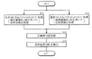
図11は、このような本実施の形態に係る位相差分布DMの生成動作(位相差検出処理)を流れ図で表したものである。この図11に示したように、位相差分布DMの生成の際に、位相差検出部143Aはまず、図7および図8を参照して前述したように、水平方向でのステレオマッチング処理を行う。言い換えると、視差画像DC,DHを用いた位相差検出処理を行う(図11のステップS11)。また、これと並行して、位相差検出部143Aは、図7および図9を参照して前述したように、垂直方向でのステレオマッチング処理を行う。言い換えると、視差画像DC,DVを用いた位相差検出処理を行う(ステップS12)。FIG. 11 is a flowchart showing the generation operation (phase difference detection process) of the phase difference distribution DM according to the present embodiment. As shown in FIG. 11, when the phase difference distribution DM is generated, the phase
次に、位相差検出部143Aは、2方向以上についての位相差検出結果(ここでは、水平方向および垂直方向についての位相差検出結果)に対してそれぞれ、位相差の信頼度判定(信頼度判定処理)を単位領域ごとに行う(ステップS13)。具体的には、例えば図8(E),(F)および図9(E),(F)に示したような、相関値演算の際の画素位置と相関値との関係を示す相関特性線の形状に基づいて、信頼度判定処理を行う。これは、図8(E)および図9(F)に示したように、正確な位相差検出がなされる場合には、相関特性線が曲線(この場合、下に凸の曲線)状となる一方、図8(F)および図9(E)に示したように、正確な位相差検出がなされない場合には相関特性線が直線状となることを利用している。このような相関特性線の形状を利用した信頼度判定処理の手法としては、例えば以下の3つの手法が挙げられる。 Next, the phase
まず、第1の手法は、以下の(4)式で規定される尖度γ(相関特性線の形状における尖っている度合いを示す指標)を用いた信頼度判定処理である。なお、この(4)式において、各画素位置iにおける相関値をXi(i=1〜N(整数))とし、これらの相関値Xiの平均値および標準偏差をそれぞれ、μ,σとしている。この尖度γの値が大きいほど、相関特性線の形状が尖っている(曲線状となっている)こと、すなわち、正確な位相差検出がなされる可能性が高い(信頼度が高い)ことを意味している。逆に、この尖度γの値が小さいほど、相関特性線の形状が尖っていない(直線状となっている)こと、すなわち、正確な位相差検出がなされる可能性が低い(信頼度が低い)ことを意味している。 First, the first method is a reliability determination process using kurtosis γ (an index indicating the degree of sharpness in the shape of the correlation characteristic line) defined by the following equation (4). In equation (4), the correlation value at each pixel position i is Xi (i = 1 to N (integer)), and the average value and standard deviation of these correlation values Xi are μ and σ, respectively. The larger the value of kurtosis γ, the sharper the correlation characteristic line is (curved), that is, the higher the possibility of accurate phase difference detection (high reliability). Means. Conversely, the smaller the value of the kurtosis γ, the less the shape of the correlation characteristic line is sharp (straight), that is, the lower the possibility that accurate phase difference detection will be performed (the reliability is lower). Low).
第2の手法は、例えば図12に示したように、相関特性線における頂点とその周辺の点とでの相関値の差分値を用いた信頼度判定処理である。すなわち、ここでは、画素位置x,(x−1),(x+1)における相関値をそれぞれ、f(x),f(x−1),f(x+1)とし、係数(定数)をαとすると、信頼度Rは以下の(5)式で規定される。この信頼度Rの値が大きいほど、相関特性線の形状が尖っている(曲線状となっている)こと、すなわち、正確な位相差検出がなされる可能性が高い(信頼度が高い)ことを意味している。逆に、この信頼度Rの値が小さいほど、相関特性線の形状が尖っていない(直線状となっている)こと、すなわち、正確な位相差検出がなされる可能性が低い(信頼度が低い)ことを意味している。
信頼度R=|α×{f(x−1)−2×f(x)+f(x+1)}| ……(5)The second method is a reliability determination process using the difference value of the correlation value between the vertex on the correlation characteristic line and the surrounding points as shown in FIG. 12, for example. That is, here, if the correlation values at pixel positions x, (x−1), and (x + 1) are f (x), f (x−1), and f (x + 1), respectively, and the coefficient (constant) is α. The reliability R is defined by the following equation (5). The larger the value of reliability R, the sharper the correlation characteristic line is (curved), that is, the higher the possibility of accurate phase difference detection (high reliability). Means. On the contrary, the smaller the value of the reliability R, the less the shape of the correlation characteristic line is sharp (straight), that is, the lower the possibility of accurate phase difference detection (the reliability is less Low).
Reliability R = | α × {f (x−1) −2 × f (x) + f (x + 1)} | (5)
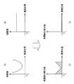
第3の手法は、例えば図13(A)〜(D)に示したように、各画素位置における相関値の微分値の積算値(積分値)を用いた信頼度判定処理である。すなわち、例えば図13(A),(C)に示したように、この相関値の微分値の積算値(図13(C)中の斜線領域の面積値に対応)が大きいほど、相関特性線の形状が尖っている(曲線状となっている)こと、すなわち、正確な位相差検出がなされる可能性が高い(信頼度が高い)ことを意味している。逆に、例えば図13(B),(D)に示したように、この相関値の微分値の積算値が小さいほど、相関特性線の形状が尖っていない(直線状となっている)こと、すなわち、正確な位相差検出がなされる可能性が低い(信頼度が低い)ことを意味している。 The third method is a reliability determination process using an integrated value (integrated value) of the differential value of the correlation value at each pixel position, for example, as shown in FIGS. That is, for example, as shown in FIGS. 13A and 13C, the correlation characteristic line increases as the integrated value of the differential value of the correlation value (corresponding to the area value of the shaded area in FIG. 13C) increases. Is sharp (curved), that is, there is a high possibility of accurate phase difference detection (high reliability). Conversely, as shown in FIGS. 13B and 13D, for example, the smaller the integrated value of the differential value of the correlation value, the less the shape of the correlation characteristic line is sharp (straight). That is, it means that the possibility of accurate phase difference detection is low (reliability is low).
最後に、位相差検出部143Aは、ステップS13における信頼度判定処理の結果に基づいて、信頼度が最も高い方向についての位相差検出結果を単位領域ごとに採用して組み合わせることにより、最終結果である位相差分布DMを生成する(ステップS14)。具体的には、ここでは、例えば水平方向についての位相差検出結果のほうが垂直方向についての位相差検出結果よりも信頼度が高くなっている単位領域では、水平方向についての位相差検出結果を採用し、その単位領域における最終的な位相差検出結果とする。一方、逆に、垂直方向についての位相差検出結果のほうが水平方向についての位相差検出結果よりも信頼度が高くなっている単位領域では、垂直方向についての位相差検出結果を採用し、その単位領域における最終的な位相差検出結果とする。このような位相差検出結果の選択(採用)を、画像全体について単位領域ごとに行うことにより、画像全体についての1つの位相差分布DMが生成される。 Finally, the phase
このようにして、本実施の形態では、複数の視差画像(ここでは3つの視差画像DC,DH,DV)において、相関値演算がなされることにより視差画像間の位相差が検出され、画像内の位相差分布DMが生成される。この際、互いに異なる2方向以上(ここでは、画像内の水平方向および垂直方向の2方向)に沿って個別に位相差検出が行われ、それら各方向についての位相差検出結果を利用して位相差分布DMが生成される。これにより、例えば画像にエッジ領域(水平エッジ領域や垂直エッジ領域)が含まれている場合であっても、ある1方向に沿った位相差検出結果のみに基づいて位相差分布が生成されている従来(比較例)の手法と比べ、位相差検出の際にエッジ領域の影響を受けにくくなる。In this way, in the present embodiment, the phase difference between the parallax images is detected by performing the correlation value calculation in a plurality of parallax images (here, three parallax images DC, DH, DV), The phase difference distribution DM is generated. At this time, phase difference detection is individually performed along two or more different directions (here, two directions in the horizontal direction and the vertical direction in the image), and the phase difference detection result in each direction is used to detect the phase difference. A phase difference distribution DM is generated. Thereby, for example, even when the image includes an edge region (horizontal edge region or vertical edge region), the phase difference distribution is generated based only on the phase difference detection result along one certain direction. compared to conventional technique of (comparative example), less susceptible to edge area when thephase difference detection.
(距離情報算出動作)
次に、リフォーカス係数算出部143では、距離情報算出部143Bが、位相差検出部143Aにおいて求められた位相差分布DMに基づいて、所定の距離情報dを算出する。この距離情報dとは、ここでは、撮像レンズ11から、撮像データD1に対応する撮像画像内における任意の基準位置までの距離の情報を意味している。詳細には、撮像レンズ11と合焦させたいリフォーカス面との間の距離情報d(撮像レンズ11から上記基準位置までの距離dの情報)、すなわち、後述するリフォーカス時の撮像レンズ11の物体側の焦点距離のことである。(Distance information calculation operation)
Next, in the refocus coefficient calculation unit 143, the distance
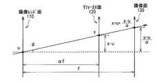
具体的には、距離情報算出部143Bは、位相差分布DMを用いて以下の(6)〜(13)式により、測定対象までの距離d(距離情報d)を算出する。ここでは、図14に示したように、撮像レンズ11の物体側焦点面をD、撮像レンズ11の焦点距離をF、位相差分布DMを求めたときの撮像レンズの開口の大きさをv、距離Dの物体を撮像したときの撮像レンズ11の像側焦点面をf、撮像レンズ11から距離dにある物体を撮像したときの撮像レンズ11の像側焦点面をg、距離dの物体を開口の大きさvを用いて計算した((Disparity)×(撮像素子13の画素Pの大きさ)×(マイクロレンズアレイ12の一辺の長さに割り当てられた画素数))の値をhとしている。 Specifically, the distance
すなわち、まず、相似関係により、以下の(6)式が得られる。また、図14により、e=(g−f)であるため、これを(6)式に代入することにより、以下の(7)式が得られ、この(7)式により以下の(8)式が得られる。また、撮像レンズ11の結像式により、以下の(9)式および(10)式が得られるため、(9)式を(8)式に代入することにより以下の(11)式が得られ、(10)式により以下の(12)式が得られる。したがって、(12)式を(11)式に代入することにより、以下の(13)式が得られるため、この(13)式中においてF,D,vの値が既知のものであれば、位相差分布DMに基づいて距離dが算出される。
(h/e)=(v/g) ……(6)
{h/(g−f)}=(v/g) ……(7)
(1/g)=(1/f)×{1−(h/v)} ……(8)
(1/F)=(1/g)+(1/d) ……(9)
(1/F)=(1/D)+(1/f) ……(10)
(1/d)=(1/F)−[(1/f)×{1−(h/v)}] ……(11)
f=F×{D/(D−F)} ……(12)
(1/d)=(1/F)−[1/{F×D/(D−F)}×{1−(h/v)}]
……(13)That is, first, the following equation (6) is obtained from the similarity relationship. Moreover, since e = (g−f) according to FIG. 14, by substituting this into the equation (6), the following equation (7) is obtained, and from this equation (7), the following (8) The formula is obtained. Moreover, since the following formulas (9) and (10) are obtained from the imaging formula of the
(H / e) = (v / g) (6)
{H / (g−f)} = (v / g) (7)
(1 / g) = (1 / f) × {1- (h / v)} (8)
(1 / F) = (1 / g) + (1 / d) (9)
(1 / F) = (1 / D) + (1 / f) (10)
(1 / d) = (1 / F) − [(1 / f) × {1− (h / v)}] (11)
f = F × {D / (D−F)} (12)
(1 / d) = (1 / F) − [1 / {F × D / (D−F)} × {1− (h / v)}]
(13)
(リフォーカス係数設定動作)
次に、リフォーカス係数算出部143では、リフォーカス係数設定部143Cが、距離情報算出部143Bにおいて求められた距離情報dに基づいて、リフォーカス係数αを設定(算出)する。具体的には、図15(A)に示したように、撮像レンズ11の物体側焦点面が距離Dだけ離れた位置にある状態で撮像された場合で考えると、以下のようになる。すなわち、図15(B)に示したように、撮像レンズ11から距離dだけ離れた位置にある平面のリフォーカス像を得るためのリフォーカス係数αは、上記(10)式および以下の(14)式により算出される。このようにして算出されたリフォーカス係数αは、撮像データD1と共に並べ替え処理部144へ入力される。
(1/F)=(1/D)+(1/αf) ……(14)(Refocus coefficient setting operation)
Next, in the refocus coefficient calculation unit 143, the refocus coefficient setting unit 143C sets (calculates) the refocus coefficient α based on the distance information d obtained by the distance
(1 / F) = (1 / D) + (1 / αf) (14)
(2−2.リフォーカス演算処理動作)
次いで、並び替え処理部144は、このようにしてリフォーカス係数算出部143において算出されたリフォーカス係数αを用いて、クランプ処理部142から供給される撮像データD1に対して所定の並べ替え処理を施し、画像データD2を生成する。具体的には、以下説明するリフォーカス演算処理(積分処理)を行うことにより、任意の焦点(リフォーカス係数αによって規定されるリフォーカス面)に設定された画像(再構築画像)を生成する。(2-2. Refocus calculation processing operation)
Next, the
ここで、図16に示したように、リフォーカス係数αによって規定されるリフォーカス面120上の座標(s,t)の撮像面130上における検出強度LF'は、以下の(15)式のように表される。また、リフォーカス面120で得られるイメージEF'(s,t)は、上記検出強度LF'をレンズ口径に関して積分したものとなるので、以下の(16)式のように表される。したがって、並び替え処理部144は、この(16)式用いてリフォーカス演算処理を行うことにより、任意の焦点(リフォーカス係数αによって規定されるリフォーカス面120)に設定された再構築画像(画像データD2)を生成することができる。Here, as shown in FIG. 16, the detected intensity LF ′ on the
なお、その後は、まず、ノイズ低減処理部145において、このようにして生成された画像データD2に対し、ノイズ低減処理を行う。次いで、輪郭強調処理部146が、ノイズ低減処理後の画像データに対し、輪郭強調処理を行う。次に、ホワイトバランス処理部147は、輪郭強調処理後の画像データに対し、色バランス調整処理(ホワイトバランス処理)を行う。そして、ガンマ補正処理部148が、ホワイトバランス処理後の画像データに対し、ガンマ補正処理を行う。これにより、画像データDoutが生成され、画像処理部14から出力される。 After that, first, the noise
以上のように本実施の形態では、複数の視差画像DC,DH,DVにおいて、相関値演算を行うことにより視差画像間の位相差を検出し、画像内の位相差分布DMを生成する際に、画像内の水平方向および垂直方向の2方向に沿って個別に位相差検出を行うと共に、それら2方向についての位相差検出結果を利用して位相差分布DMを生成するようにしたので、位相差検出の際に、従来と比べてエッジ領域の影響を受けにくくすることができる。よって、従来と比べて正確な位相差分布DMを生成することが可能となり、その結果、この位相差分布DMに基づいて得られる距離情報d(距離情報分布)についても、従来と比べて正確なものとすることが可能となる。 As described above, in the present embodiment, when a phase difference between parallax images is detected by performing correlation value calculation in a plurality of parallax images DC, DH, and DV, and a phase difference distribution DM in the image is generated. Since the phase difference detection is individually performed along the two directions of the horizontal direction and the vertical direction in the image, and the phase difference distribution DM is generated by using the phase difference detection results in these two directions. When detecting the phase difference, it is possible to make it less susceptible to the influence of the edge region than in the conventional case. Therefore, it is possible to generate a phase difference distribution DM that is more accurate than the conventional one. As a result, distance information d (distance information distribution) obtained based on the phase difference distribution DM is also more accurate than the conventional one. It becomes possible.
<第2の実施の形態>
続いて、本発明の第2の実施の形態について説明する。本実施の形態は、位相差検出部143Aにおいて、図11に示した位相差検出処理の代わりに、以下説明する位相差検出処理を行うようにしたものであり、他の構成および動作については上記第1の実施の形態と同様となっている。なお、第1の実施の形態における構成要素と同一のものには同一の符号を付し、適宜説明を省略する。<Second Embodiment>
Next, a second embodiment of the present invention will be described. In the present embodiment, the phase
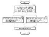
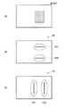
図17は、本実施の形態に係る位相差分布DMの生成動作(位相差検出処理)を流れ図で表したものである。本実施の形態では、位相差検出部143Aは位相差分布DMの生成の際に、まず、2方向以上に沿った複数の視差画像のうちの少なくとも1つに対して、その視差方向に沿ったエッジ領域を検出するエッジ検出処理を行う。具体的には、ここでは、水平方向の視差画像DHに対して、水平方向に沿ったエッジ領域(水平エッジ領域)を検出する水平エッジ検出処理を行う。あるいは、垂直方向の視差画像DVに対して、垂直方向に沿ったエッジ領域(垂直エッジ領域)を検出する垂直エッジ検出処理を行う(図17のステップS21)。 FIG. 17 is a flowchart showing the generation operation (phase difference detection process) of the phase difference distribution DM according to this embodiment. In the present embodiment, when generating the phase difference distribution DM, the phase
すなわち、例えば図18(A)に示したようなエッジ領域を含む視差画像DHに対して水平エッジ検出処理を行った場合には、例えば図18(B)に示したような水平エッジ領域PH1,PH2が検出される水平エッジ検出結果が得られる。一方、図18(A)に示した視差画像が視差画像DVである場合には、この視差画像DVに対して垂直エッジ検出処理を行った場合、例えば図18(C)に示したような垂直エッジ領域PV1,PV2が検出される垂直エッジ検出結果が得られる。 That is, for example, when the horizontal edge detection process is performed on the parallax image DH including the edge region as illustrated in FIG. 18A, for example, the horizontal edge region PH1, as illustrated in FIG. A horizontal edge detection result from which PH2 is detected is obtained. On the other hand, when the parallax image shown in FIG. 18A is a parallax image DV, when vertical edge detection processing is performed on the parallax image DV, for example, the vertical as shown in FIG. A vertical edge detection result in which the edge regions PV1 and PV2 are detected is obtained.
ここで、このようなエッジ検出処理の際に用いるフィルタ(エッジ検出フィルタ)としては、例えば図19(A),(B)に示したようなSobelフィルタが挙げられる。具体的には、例えば図19(A)に示したSobelフィルタは、水平エッジ検出フィルタとして機能し、例えば図19(B)に示したSobelフィルタは、垂直エッジ検出フィルタとして機能する。なお、エッジ検出処理前の画像における画素値をimg(x,y)等、エッジ検出処理後の画像における画素値をS(x,y)等、とすると、水平エッジ検出フィルタおよび垂直エッジ検出フィルタとして機能するSobelフィルタはそれぞれ、以下の(17)式および(18)式により表わされる。 Here, as a filter (edge detection filter) used in such edge detection processing, for example, a Sobel filter as shown in FIGS. 19A and 19B can be cited. Specifically, for example, the Sobel filter illustrated in FIG. 19A functions as a horizontal edge detection filter, and for example, the Sobel filter illustrated in FIG. 19B functions as a vertical edge detection filter. If the pixel value in the image before the edge detection process is img (x, y) and the pixel value in the image after the edge detection process is S (x, y), the horizontal edge detection filter and the vertical edge detection filter The Sobel filters functioning as are expressed by the following equations (17) and (18), respectively.
次に、位相差検出部143Aは、ステップS21におけるエッジ検出結果に基づいて、検出されたエッジ領域の方向とは異なる方向についての位相差検出結果を単位領域ごとに採用して組み合わせることにより、位相差分布DMを生成する。具体的には、ここでは、水平方向でのステレオマッチング処理(視差画像DC,DHを用いた位相差検出処理)(ステップS22)と、垂直方向でのステレオマッチング処理(視差画像DC,DVを用いた位相差検出処理)(ステップS23)とを組み合わせる。 Next, based on the edge detection result in step S21, the phase
詳細には、位相差検出部143Aは、ステップS21におけるエッジ検出処理の際にエッジ領域が検出されなかった単位領域については、そのエッジ検出処理の方向と同じ方向に沿って位相差検出処理を行う。また、エッジ検出処理の際にエッジ領域が検出された単位領域については、そのエッジ検出処理の方向とは異なる方向のうちの1つの方向に沿って位相差検出処理を行う。これにより、後述するステップS24においてこれらの位相差検出結果を組み合わせる際に、不要(無駄)な位相差検出処理を行った単位領域が生じないため、位相差検出動作(位相差分布DMの生成動作)全体の処理が高速化すると共に、計算コスト低減も図られる。 Specifically, the phase
すなわち、ここでは、例えばステップS21において水平エッジ検出処理を行った場合には、水平エッジ領域が検出されなかった単位領域については、ステップS22において、水平方向に沿った位相差検出処理を行う。一方、この場合、水平エッジ領域が検出された単位領域については、ステップS23において、垂直方向に沿った位相差検出処理を行う。 That is, here, for example, when the horizontal edge detection process is performed in step S21, the phase difference detection process along the horizontal direction is performed in step S22 for the unit area in which the horizontal edge area is not detected. On the other hand, in this case, for the unit area in which the horizontal edge area is detected, a phase difference detection process along the vertical direction is performed in step S23.
また、例えばステップS21において垂直エッジ検出処理を行った場合には、垂直エッジ領域が検出されなかった単位領域については、ステップS23において、垂直方向に沿った位相差検出処理を行う。一方、この場合、垂直エッジ領域が検出された単位領域については、ステップS22において、水平方向に沿った位相差検出処理を行う。 For example, when the vertical edge detection process is performed in step S21, the phase difference detection process along the vertical direction is performed in step S23 for the unit area in which the vertical edge area is not detected. On the other hand, in this case, for the unit area in which the vertical edge area is detected, a phase difference detection process along the horizontal direction is performed in step S22.
最後に、位相差検出部143Aは、ステップS22,S23において行った水平方向および垂直方向についての位相差検出結果を、単位領域ごとに組み合わせることにより、最終結果である位相差分布DMを生成する(ステップS24)。 Finally, the phase
このように、本実施の形態においても上記第1の実施の形態と同様に、位相差検出の際に、従来と比べてエッジ領域の影響を受けにくくすることができる。よって、従来と比べて正確な位相差分布DMを生成することが可能となり、その結果、この位相差分布DMに基づいて得られる距離情報d(距離情報分布)についても、従来と比べて正確なものとすることが可能となる。 As described above, also in the present embodiment, as in the first embodiment, it is possible to make the phase difference detection less susceptible to the influence of the edge region than in the conventional case. Therefore, it is possible to generate a phase difference distribution DM that is more accurate than the conventional one. As a result, distance information d (distance information distribution) obtained based on the phase difference distribution DM is also more accurate than the conventional one. It becomes possible.
なお、本実施の形態では、図17に示したように、エッジ検出処理を行ったのちに各方向についての位相差検出処理を行う場合について説明したが、この順序で処理を行う場合には限られず、例えば逆の順序で処理を行うようにしてもよい。すなわち、各方向についての位相差検出処理を行ったのちにエッジ検出処理を行うようにしてもよい。ただし、本実施の形態の順序で処理を行った場合には、上記したように、エッジ検出処理の結果を考慮して、単位領域ごとに選択的な位相差検出処理を行うことが可能となる。そのため、本実施の形態のほうが、位相差検出動作(位相差分布DMの生成動作)全体の処理を高速化することができると共に、計算コストも低減させることが可能となる。 In the present embodiment, as illustrated in FIG. 17, the case where the phase difference detection process in each direction is performed after the edge detection process has been described, but this is not limited to the case where the processes are performed in this order. However, for example, the processing may be performed in the reverse order. That is, the edge detection process may be performed after the phase difference detection process for each direction. However, when processing is performed in the order of the present embodiment, it is possible to perform selective phase difference detection processing for each unit region in consideration of the result of edge detection processing as described above. . For this reason, the present embodiment can speed up the overall processing of the phase difference detection operation (the generation operation of the phase difference distribution DM), and can also reduce the calculation cost.
<適用例>
続いて、上記第1および第2の実施の形態において説明した撮像装置1の適用例について説明する。これらの実施の形態に係る撮像装置1は、例えば以下のようなデジタルカメラ3の他、位置センサや生体センサ、光学顕微鏡などに適用することが可能である。<Application example>
Next, application examples of the
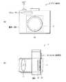
図20(A),(B)は、上記撮像装置1を搭載したデジタルカメラ3の概略構成を表したものであり、(A)は正面図、(B)は側面図である。このデジタルカメラ3は、筐体300の内部に撮像装置1を備えており、筐体300の上部には、シャッタ17、フラッシュ18およびファインダ光学系19などが設けられている。 20A and 20B show a schematic configuration of the
<変形例>
以上、実施の形態および適用例を挙げて本発明を説明したが、本発明はこれらの実施の形態等に限定されるものではなく、種々の変形が可能である。<Modification>
While the present invention has been described with the embodiments and application examples, the present invention is not limited to these embodiments and the like, and various modifications are possible.
例えば、上記実施の形態等では、位相差検出部143Aにおいて、3つの視差画像DC,DH,DVを用いて位相差分布DMの生成を行っているが、この場合には限定されず、4つ以上の視差画像を用いて位相差分布DMを生成するようにしてもよい。For example, in the above embodiment and the like, the phase
また、上記実施の形態等では、複数の視差画像における水平方向および垂直方向に沿って個別に位相差検出処理を行う場合について説明したが、この場合には限定されず、例えば画像内の斜め方向に沿った位相差検出処理を利用するようにしてもよい。すなわち、互いに異なる2方向以上に沿って個別に位相差検出処理を行うのであれば、位相差検出処理を行う方向については任意の方向を用いることが可能である。 In the above-described embodiment and the like, the case where the phase difference detection processing is individually performed along the horizontal direction and the vertical direction in a plurality of parallax images has been described. However, the present invention is not limited to this case. The phase difference detection process along the line may be used. That is, as long as the phase difference detection process is performed individually along two or more different directions, any direction can be used as the direction in which the phase difference detection process is performed.
更に、上記実施の形態等では、位相差検出部143Aにより生成された位相差分布DMに基づいて、距離情報d(撮像レンズ11からリフォーカス面までの距離情報)を算出する場合について説明したが、この場合には限られない。すなわち、生成された位相差分布に基づいて他のパラメータを算出する場合(例えば、中間視差画像生成処理や、視差強調処理など)にも、本発明を適用することが可能である。 Further, in the above-described embodiment and the like, the case has been described where distance information d (distance information from the
加えて、上記実施の形態等では、画像処理部14において行われる並び替え処理を含む画像処理の一例として、「Light Field Photography」を利用したリフォーカス演算処理について説明したが、並び替え処理を含む画像処理としてはこれには限られない。すなわち、例えば、焦点ぼかし処理や被写体深度調整処理などに対して適用するようにしてもよい。 In addition, in the above-described embodiment and the like, the refocus calculation process using “Light Field Photography” is described as an example of the image process including the rearrangement process performed in the
また、上記実施の形態では、画像処理部14を撮像装置1の構成要素の一つとして説明したが、必ずしもこの画像処理部14が撮像装置1の内部に設けられている必要はない。具体的には、デジタルカメラ3の筐体300内において、画像処理部を撮像装置とは別に設けておくと共に、この画像処理部によって、撮像装置で得られた撮像データに対して画像処理を施すようにしてもよい。 In the above embodiment, the
更に、上記実施の形態等では、画像処理部14において、「Light Field Photography」を利用した撮像光学系(撮像レンズ11、マイクロレンズアレイ12および撮像素子13を有する撮像光学系)により得られた撮像データD0に対して画像処理を行う場合について説明したが、この場合には限られない。すなわち、このような撮像光学系により光線の進行方向を保持した状態で取得された撮像データ以外にも、本発明を適用することが可能である。具体的には、例えば、複数の視差を有する撮像光学系を用いて取得された複数の視差画像に基づいて、位相差分布を生成するようにしてもよい。 Furthermore, in the above-described embodiment and the like, the
加えて、上記実施の形態では、開口絞り10の位置を撮像レンズの被写体側(入射側)に配置した構成としているが、これに限定されず、撮像レンズの像側(出射側)あるいは、撮像レンズ内部に設けられた構成であってもよい。In addition, in the above embodiment, the position of the
また、上記実施の形態等では、カラーフィルタの一例として、赤(R)、緑(G)および青(B)の3原色のカラーフィルタがR:G:B=1:2:1の比率で市松状に配置されたBayer配列のカラーフィルタを挙げて説明したが、これには限らない。すなわち、例えば補色フィルタなどの他の配列のカラーフィルタを用いるようにしてもよい。このような補色フィルタとしては、例えば、黄(Y)、マゼンダ(M)、シアン(C)および緑(G)の4補色のカラーフィルタが、Y:M:C:G=1:1:1:1の比率で市松状に配置されたものが挙げられる。 In the above-described embodiment and the like, as an example of the color filter, the color filters of the three primary colors of red (R), green (G), and blue (B) are in a ratio of R: G: B = 1: 2: 1. Although a Bayer color filter arranged in a checkered pattern has been described, the present invention is not limited to this. That is, for example, a color filter of another arrangement such as a complementary color filter may be used. As such complementary color filters, for example, four complementary color filters of yellow (Y), magenta (M), cyan (C) and green (G) are Y: M: C: G = 1: 1: 1. One that is arranged in a checkered pattern at a ratio of: 1.
1…撮像装置、10…開口絞り、11…撮像レンズ、12…マイクロレンズアレイ、13…撮像素子、14…画像処理部、141…欠陥補正部、142…クランプ処理部、143…リフォーカス係数算出部、143A…位相差検出部、143B…距離情報算出部、143C…リフォーカス係数設定部、144…並び替え処理部、145…ノイズ低減処理部、146…輪郭強調処理部、147…ホワイトバランス処理部、148…ガンマ補正処理部、15…撮像素子駆動部、16…制御部、2…撮像対象物(被写体)、3…デジタルカメラ、D0,D1,D2,Dout…撮像データ(画像データ)、DM,DM1…位相差分布(Disparity Map)、d…距離情報、α…リフォーカス係数、LR,LL…視差画像の光線、φR,φL…視差画像の位相、Δφ…位相差、DC,DH,DV…視差画像、C1,C2,H1,H2,V1,V2…部分画像、H10,H20,V10,V20…比較範囲、EH,EV…エッジ検出結果(エッジ検出画像)、PH1,PH2…水平エッジ領域、PV1,PV2…垂直エッジ領域。 DESCRIPTION OF
Claims (14)
Translated fromJapanese前記位相差検出部は、互いに異なる2方向以上に沿って個別に位相差検出を行うと共に、それら2方向以上についての位相差検出結果を利用して、前記位相差分布を生成する
画像処理装置。A phase difference detection unit that detects a phase difference between parallax images by performing a correlation value calculation in a plurality of parallax images, and generates a phase difference distribution in the images,
The image processing device, wherein the phase difference detection unit individually performs phase difference detection along two or more different directions, and generates the phase difference distribution using phase difference detection results for the two or more directions.
前記2方向以上についての位相差検出結果に対してそれぞれ、位相差の信頼度判定を単位領域ごとに行うと共に、
それらの信頼度判定結果に基づいて、信頼度が最も高い方向についての位相差検出結果を単位領域ごとに採用して組み合わせることにより、前記位相差分布を生成する
請求項1に記載の画像処理装置。The phase difference detector is
For each of the phase difference detection results for the two or more directions, phase difference reliability determination is performed for each unit region, and
The image processing apparatus according to claim 1, wherein the phase difference distribution is generated by adopting and combining the phase difference detection results for the direction with the highest reliability based on the reliability determination results for each unit region. .
請求項2に記載の画像処理装置。The image processing apparatus according to claim 2, wherein the phase difference detection unit performs the reliability determination based on a shape of a correlation characteristic line indicating a relationship between a pixel position and a correlation value in the correlation value calculation.
前記2方向以上の視差画像のうちの少なくとも1つについて、その視差方向に沿ったエッジ領域を検出するエッジ検出処理を行うと共に、
そのエッジ検出結果に基づいて、検出されたエッジ領域の方向とは異なる方向についての位相差検出結果を単位領域ごとに採用して組み合わせることにより、前記位相差分布を生成する
請求項1に記載の画像処理装置。The phase difference detector is
For at least one of the two or more parallax images, an edge detection process for detecting an edge region along the parallax direction is performed,
The phase difference distribution is generated based on the edge detection result by adopting and combining the phase difference detection results for the direction different from the direction of the detected edge region for each unit region. Image processing device.
前記エッジ検出処理の際にエッジ領域が検出されなかった単位領域については、そのエッジ検出処理の方向と同じ方向に沿って位相差検出を行うと共に、
前記エッジ検出処理の際にエッジ領域が検出された単位領域については、そのエッジ検出処理の方向とは異なる方向のうちの1つの方向に沿って位相差検出を行う
請求項4に記載の画像処理装置。The phase difference detector is
For the unit area in which the edge area is not detected during the edge detection process, the phase difference is detected along the same direction as the edge detection process, and
5. The image processing according to claim 4, wherein the phase difference is detected along one of the directions different from the direction of the edge detection processing for the unit region in which the edge region is detected during the edge detection processing. apparatus.
前記複数の視差画像における水平方向および垂直方向に沿って個別に位相差検出を行うと共に、
前記水平方向についての位相差検出結果と、前記垂直方向についての位相差検出結果とを利用して、前記位相差分布を生成する
請求項1ないし請求項5のいずれか1項に記載の画像処理装置。The phase difference detector is
Performing phase difference detection individually along the horizontal and vertical directions in the plurality of parallax images,
The image processing according to any one of claims 1 to 5, wherein the phase difference distribution is generated by using a phase difference detection result in the horizontal direction and a phase difference detection result in the vertical direction. apparatus.
撮像レンズと、受光光線に基づいて撮像データを取得する撮像素子と、前記撮像レンズと前記撮像素子との間に配置され、前記撮像素子の複数の画素に対して1つのマイクロレンズが割り当てられてなるマイクロレンズアレイとを有する撮像光学系により、
光線の進行方向を保持した状態で取得された撮像データに基づいて生成されたものである
請求項1ないし請求項5のいずれか1項に記載の画像処理装置。The plurality of parallax images are
An image pickup lens, an image pickup device that acquires image pickup data based on a received light beam, and the image pickup lens are arranged between the image pickup lens and one micro lens assigned to a plurality of pixels of the image pickup device. An imaging optical system having a microlens array
The image processing apparatus according to claim 1, wherein the image processing apparatus is generated based on imaging data acquired in a state in which a traveling direction of a light beam is maintained.
請求項7に記載の画像処理装置。The image processing apparatus according to claim 7, further comprising: a distance information calculation unit that calculates distance information from the imaging lens to the refocus plane based on the phase difference distribution generated by the phase difference detection unit.
請求項8に記載の画像処理装置。The image processing apparatus according to claim 8, further comprising a refocus coefficient setting unit configured to set a refocus coefficient based on the distance information calculated by the distance informationcalculation unit.
請求項9に記載の画像処理装置。The image processing apparatus according to claim 9, further comprising a rearrangement processing unit that performs a rearrangement process on the imaging data using the refocus coefficient set by the refocus coefficient setting unit.
互いに異なる2方向以上に沿って個別に位相差検出を行うと共に、それら2方向以上についての位相差検出結果を利用して、前記位相差分布を生成する
画像処理方法。When detecting a phase difference between parallax images by performing a correlation value calculation in a plurality of parallax images, and generating a phase difference distribution in the images,
An image processing method for performing phase difference detection individually along two or more different directions and generating the phase difference distribution using phase difference detection results for two or more directions.
前記位相差検出ステップにおいて、互いに異なる2方向以上に沿って個別に位相差検出を行うと共に、それら2方向以上についての位相差検出結果を利用して、前記位相差分布を生成する
画像処理プログラム。When a phase difference detection step for detecting a phase difference between parallax images by performing a correlation value calculation in a plurality of parallax images and generating a phase difference distribution in the images is executed by the computer,
An image processing program for performing phase difference detection individually along two or more different directions in the phase difference detection step and generating the phase difference distribution using phase difference detection results for the two or more directions.
前記撮像光学系により取得された撮像データに対して画像処理を行う画像処理装置と
を備え、
前記画像処理装置は、前記撮像データから直接もしくは間接的に得られる複数の視差画像において、相関値演算を行うことにより視差画像間の位相差を検出し、画像内の位相差分布を生成する位相差検出部を有し、
前記位相差検出部は、互いに異なる2方向以上に沿って個別に位相差検出を行うと共に、それら2方向以上についての位相差検出結果を利用して、前記位相差分布を生成する
撮像装置。An imaging optical system;
An image processing device that performs image processing on imaging data acquired by the imaging optical system,
The image processing apparatus detects a phase difference between parallax images by performing correlation value calculation in a plurality of parallax images obtained directly or indirectly from the imaging data, and generates a phase difference distribution in the image. Having a phase difference detector,
The phase difference detection unit individually performs phase difference detection along two or more different directions, and generates the phase difference distribution using phase difference detection results for the two or more directions.
撮像レンズと、
受光光線に基づいて前記撮像データを取得する撮像素子と、
前記撮像レンズと前記撮像素子との間に配置され、前記撮像素子の複数の画素に対して1つのマイクロレンズが割り当てられてなるマイクロレンズアレイと
を有し、
前記複数の視差画像は、光線の進行方向を保持した状態で取得された前記撮像データに基づいて生成されたものである
請求項13に記載の撮像装置。The imaging optical system is
An imaging lens;
An image sensor that acquires the imaging data based on a received light beam;
A microlens array that is disposed between the imaging lens and the imaging element and in which one microlens is assigned to a plurality of pixels of the imaging element;
The imaging device according to claim 13, wherein the plurality of parallax images are generated based on the imaging data acquired in a state in which a traveling direction of light rays is maintained.
Priority Applications (4)
| Application Number | Priority Date | Filing Date | Title |
|---|---|---|---|
| JP2010031833AJP5387856B2 (en) | 2010-02-16 | 2010-02-16 | Image processing apparatus, image processing method, image processing program, and imaging apparatus |
| US13/024,054US9131222B2 (en) | 2010-02-16 | 2011-02-09 | Phase difference detection method, program, and device |
| CN201110035176.7ACN102164293B (en) | 2010-02-16 | 2011-02-09 | Image processing apparatus, image processing method and imaging device |
| US14/809,776US10015472B2 (en) | 2010-02-16 | 2015-07-27 | Image processing using distance information |
Applications Claiming Priority (1)
| Application Number | Priority Date | Filing Date | Title |
|---|---|---|---|
| JP2010031833AJP5387856B2 (en) | 2010-02-16 | 2010-02-16 | Image processing apparatus, image processing method, image processing program, and imaging apparatus |
Related Child Applications (1)
| Application Number | Title | Priority Date | Filing Date |
|---|---|---|---|
| JP2013191785ADivisionJP5673764B2 (en) | 2013-09-17 | 2013-09-17 | Image processing apparatus, image processing method, image processing program, and recording medium |
Publications (3)
| Publication Number | Publication Date |
|---|---|
| JP2011171858A JP2011171858A (en) | 2011-09-01 |
| JP2011171858A5 JP2011171858A5 (en) | 2013-03-14 |
| JP5387856B2true JP5387856B2 (en) | 2014-01-15 |
Family
ID=44369388
Family Applications (1)
| Application Number | Title | Priority Date | Filing Date |
|---|---|---|---|
| JP2010031833AExpired - Fee RelatedJP5387856B2 (en) | 2010-02-16 | 2010-02-16 | Image processing apparatus, image processing method, image processing program, and imaging apparatus |
Country Status (3)
| Country | Link |
|---|---|
| US (2) | US9131222B2 (en) |
| JP (1) | JP5387856B2 (en) |
| CN (1) | CN102164293B (en) |
Families Citing this family (101)
| Publication number | Priority date | Publication date | Assignee | Title |
|---|---|---|---|---|
| JPS5992792A (en)* | 1982-11-15 | 1984-05-29 | Mitsubishi Electric Corp | Induction motor torque control device |
| US8866920B2 (en) | 2008-05-20 | 2014-10-21 | Pelican Imaging Corporation | Capturing and processing of images using monolithic camera array with heterogeneous imagers |
| DK3876510T3 (en) | 2008-05-20 | 2024-11-11 | Adeia Imaging Llc | CAPTURE AND PROCESSING OF IMAGES USING MONOLITHIC CAMERA ARRAY WITH HETEROGENEOUS IMAGES |
| US11792538B2 (en) | 2008-05-20 | 2023-10-17 | Adeia Imaging Llc | Capturing and processing of images including occlusions focused on an image sensor by a lens stack array |
| EP2502115A4 (en) | 2009-11-20 | 2013-11-06 | Pelican Imaging Corp | CAPTURE AND IMAGE PROCESSING USING A MONOLITHIC CAMERAS NETWORK EQUIPPED WITH HETEROGENEOUS IMAGERS |
| US8928793B2 (en) | 2010-05-12 | 2015-01-06 | Pelican Imaging Corporation | Imager array interfaces |
| US8878950B2 (en) | 2010-12-14 | 2014-11-04 | Pelican Imaging Corporation | Systems and methods for synthesizing high resolution images using super-resolution processes |
| EP2708019B1 (en) | 2011-05-11 | 2019-10-16 | FotoNation Limited | Systems and methods for transmitting and receiving array camera image data |
| US8531581B2 (en) | 2011-05-23 | 2013-09-10 | Ricoh Co., Ltd. | Focusing and focus metrics for a plenoptic imaging system |
| JP5206853B2 (en)* | 2011-09-08 | 2013-06-12 | カシオ計算機株式会社 | Interpolated image generating device, reconstructed image generating device, interpolated image generating method, and program |
| US20130070060A1 (en) | 2011-09-19 | 2013-03-21 | Pelican Imaging Corporation | Systems and methods for determining depth from multiple views of a scene that include aliasing using hypothesized fusion |
| EP2760209B1 (en)* | 2011-09-21 | 2017-07-12 | FUJIFILM Corporation | Image processing device, method, program and recording medium, stereoscopic image capture device, portable electronic apparatus, printer, and stereoscopic image player device |
| CN104081414B (en) | 2011-09-28 | 2017-08-01 | Fotonation开曼有限公司 | Systems and methods for encoding and decoding light field image files |
| CN103139470A (en)* | 2011-11-30 | 2013-06-05 | 索尼公司 | Digital imaging system |
| JP5943596B2 (en)* | 2011-12-19 | 2016-07-05 | キヤノン株式会社 | Imaging device |
| JP5858773B2 (en)* | 2011-12-22 | 2016-02-10 | キヤノン株式会社 | Three-dimensional measurement method, three-dimensional measurement program, and robot apparatus |
| US20130162763A1 (en)* | 2011-12-23 | 2013-06-27 | Chao-Chung Cheng | Method and apparatus for adjusting depth-related information map according to quality measurement result of the depth-related information map |
| US9571810B2 (en) | 2011-12-23 | 2017-02-14 | Mediatek Inc. | Method and apparatus of determining perspective model for depth map generation by utilizing region-based analysis and/or temporal smoothing |
| US9137441B2 (en) | 2012-02-16 | 2015-09-15 | Ricoh Co., Ltd. | Spatial reconstruction of plenoptic images |
| EP2817955B1 (en) | 2012-02-21 | 2018-04-11 | FotoNation Cayman Limited | Systems and methods for the manipulation of captured light field image data |
| JP5929553B2 (en) | 2012-06-28 | 2016-06-08 | ソニー株式会社 | Image processing apparatus, imaging apparatus, image processing method, and program |
| JP2015534734A (en) | 2012-06-28 | 2015-12-03 | ペリカン イメージング コーポレイション | System and method for detecting defective camera arrays, optical arrays, and sensors |
| US20140002674A1 (en)* | 2012-06-30 | 2014-01-02 | Pelican Imaging Corporation | Systems and Methods for Manufacturing Camera Modules Using Active Alignment of Lens Stack Arrays and Sensors |
| US9509970B2 (en)* | 2012-07-18 | 2016-11-29 | Qualcomm Incorporated | Crosstalk reduction with location-based adjustment in multiview video processing |
| US9083948B2 (en)* | 2012-07-18 | 2015-07-14 | Qualcomm Incorporated | Crosstalk reduction in multiview video processing |
| JP6039301B2 (en)* | 2012-08-09 | 2016-12-07 | キヤノン株式会社 | IMAGING DEVICE, IMAGING SYSTEM, IMAGING DEVICE CONTROL METHOD, PROGRAM, AND STORAGE MEDIUM |
| PL4296963T3 (en) | 2012-08-21 | 2025-04-28 | Adeia Imaging Llc | Method for depth detection in images captured using array cameras |
| WO2014032020A2 (en) | 2012-08-23 | 2014-02-27 | Pelican Imaging Corporation | Feature based high resolution motion estimation from low resolution images captured using an array source |
| CN104584545B (en) | 2012-08-31 | 2017-05-31 | 索尼公司 | Image processing apparatus, image processing method and information processor |
| JP5988790B2 (en)* | 2012-09-12 | 2016-09-07 | キヤノン株式会社 | Image processing apparatus, imaging apparatus, image processing method, and image processing program |
| JP5943785B2 (en)* | 2012-09-12 | 2016-07-05 | キヤノン株式会社 | IMAGING DEVICE, IMAGING SYSTEM, IMAGE PROCESSING DEVICE, AND IMAGING DEVICE CONTROL METHOD |
| JP6074201B2 (en)* | 2012-09-21 | 2017-02-01 | キヤノン株式会社 | Image processing apparatus, control method, and program |
| EP4307659A1 (en) | 2012-09-28 | 2024-01-17 | Adeia Imaging LLC | Generating images from light fields utilizing virtual viewpoints |
| JP5820794B2 (en)* | 2012-10-05 | 2015-11-24 | オリンパス株式会社 | Imaging device |
| CN103489183B (en)* | 2012-10-17 | 2017-10-10 | 深圳市瑞工科技有限公司 | A kind of sectional perspective matching process split based on edge with seed point |
| JP2014086863A (en)* | 2012-10-23 | 2014-05-12 | Sony Corp | Imaging device, image processing method, and program |
| US10134136B2 (en) | 2012-10-24 | 2018-11-20 | Sony Corporation | Image processing apparatus and image processing method |
| US9137524B2 (en)* | 2012-11-27 | 2015-09-15 | Qualcomm Incorporated | System and method for generating 3-D plenoptic video images |
| JP6055332B2 (en)* | 2013-02-12 | 2016-12-27 | キヤノン株式会社 | Image processing apparatus, imaging apparatus, control method, and program |
| US9774789B2 (en) | 2013-03-08 | 2017-09-26 | Fotonation Cayman Limited | Systems and methods for high dynamic range imaging using array cameras |
| US8866912B2 (en) | 2013-03-10 | 2014-10-21 | Pelican Imaging Corporation | System and methods for calibration of an array camera using a single captured image |
| US9124831B2 (en) | 2013-03-13 | 2015-09-01 | Pelican Imaging Corporation | System and methods for calibration of an array camera |
| WO2014153098A1 (en) | 2013-03-14 | 2014-09-25 | Pelican Imaging Corporation | Photmetric normalization in array cameras |
| US9578259B2 (en)* | 2013-03-14 | 2017-02-21 | Fotonation Cayman Limited | Systems and methods for reducing motion blur in images or video in ultra low light with array cameras |
| US9445003B1 (en) | 2013-03-15 | 2016-09-13 | Pelican Imaging Corporation | Systems and methods for synthesizing high resolution images using image deconvolution based on motion and depth information |
| US9497429B2 (en) | 2013-03-15 | 2016-11-15 | Pelican Imaging Corporation | Extended color processing on pelican array cameras |
| US10122993B2 (en) | 2013-03-15 | 2018-11-06 | Fotonation Limited | Autofocus system for a conventional camera that uses depth information from an array camera |
| US9438888B2 (en) | 2013-03-15 | 2016-09-06 | Pelican Imaging Corporation | Systems and methods for stereo imaging with camera arrays |
| WO2014196374A1 (en)* | 2013-06-05 | 2014-12-11 | ソニー株式会社 | Image processing device and image processing method |
| JP6292785B2 (en)* | 2013-07-22 | 2018-03-14 | キヤノン株式会社 | Image processing apparatus, image processing method, and program |
| EP3035282A4 (en) | 2013-09-11 | 2017-07-05 | Sony Corporation | Image processing device and method |
| WO2015037473A1 (en) | 2013-09-11 | 2015-03-19 | ソニー株式会社 | Image processing device and method |
| JP6476658B2 (en) | 2013-09-11 | 2019-03-06 | ソニー株式会社 | Image processing apparatus and method |
| US9898856B2 (en) | 2013-09-27 | 2018-02-20 | Fotonation Cayman Limited | Systems and methods for depth-assisted perspective distortion correction |
| US10119808B2 (en) | 2013-11-18 | 2018-11-06 | Fotonation Limited | Systems and methods for estimating depth from projected texture using camera arrays |
| WO2015081279A1 (en) | 2013-11-26 | 2015-06-04 | Pelican Imaging Corporation | Array camera configurations incorporating multiple constituent array cameras |
| EP2879091A1 (en)* | 2013-11-29 | 2015-06-03 | Thomson Licensing | Method and device for estimating disparity associated with views of a scene acquired with a plenoptic camera |
| CN105980905B (en)* | 2014-02-13 | 2018-04-27 | 富士胶片株式会社 | Camera device and focus control method |
| US10089740B2 (en) | 2014-03-07 | 2018-10-02 | Fotonation Limited | System and methods for depth regularization and semiautomatic interactive matting using RGB-D images |
| JP2017531976A (en) | 2014-09-29 | 2017-10-26 | フォトネイション ケイマン リミテッド | System and method for dynamically calibrating an array camera |
| EP3228977A4 (en)* | 2014-12-01 | 2018-07-04 | Sony Corporation | Image-processing device and image-processing method |
| JP6408893B2 (en)* | 2014-12-16 | 2018-10-17 | オリンパス株式会社 | 3D position information acquisition method and 3D position information acquisition apparatus |
| CN104834081B (en)* | 2015-04-10 | 2017-01-18 | 宁波大学 | Rapid automatic focusing method for stereoscopic microscope |
| KR102324605B1 (en)* | 2015-05-26 | 2021-11-10 | 한국전자통신연구원 | Method and apparatus for generating disparity image |
| KR101832189B1 (en)* | 2015-07-29 | 2018-02-26 | 야마하하쓰도키 가부시키가이샤 | Abnormal image detecting apparatus, image processing system with abnormal image detecting apparatus and vehicle mounted with image processing system |
| JP6843552B2 (en) | 2016-08-23 | 2021-03-17 | キヤノン株式会社 | Image processing equipment, image processing methods and programs. |
| CN106331499B (en)* | 2016-09-13 | 2019-10-29 | 努比亚技术有限公司 | Focusing method and photographing device |
| CN108389169B (en)* | 2018-03-07 | 2021-11-09 | 哈尔滨工业大学 | Temperature reconstruction method applied to flame light field refocusing imaging |
| CN110891131B (en) | 2018-09-10 | 2025-03-18 | 北京小米移动软件有限公司 | Camera module, processing method and device, electronic device, and storage medium |
| US11270110B2 (en) | 2019-09-17 | 2022-03-08 | Boston Polarimetrics, Inc. | Systems and methods for surface modeling using polarization cues |
| WO2021071992A1 (en) | 2019-10-07 | 2021-04-15 | Boston Polarimetrics, Inc. | Systems and methods for augmentation of sensor systems and imaging systems with polarization |
| CN112866510B (en)* | 2019-11-12 | 2022-06-10 | Oppo广东移动通信有限公司 | Focusing method and device, electronic equipment and computer readable storage medium |
| CN112866545B (en)* | 2019-11-12 | 2022-11-15 | Oppo广东移动通信有限公司 | Focus control method and device, electronic device, computer-readable storage medium |
| CN112866542B (en)* | 2019-11-12 | 2022-08-12 | Oppo广东移动通信有限公司 | Focus tracking method and device, electronic device, computer-readable storage medium |
| CN112866675B (en)* | 2019-11-12 | 2022-09-09 | Oppo广东移动通信有限公司 | Depth map generation method and apparatus, electronic device, and computer-readable storage medium |
| CN112866548B (en)* | 2019-11-12 | 2022-06-14 | Oppo广东移动通信有限公司 | Method and device for obtaining phase difference, and electronic device |
| CN112866546B (en)* | 2019-11-12 | 2022-09-27 | Oppo广东移动通信有限公司 | Focusing method and device, electronic equipment and computer readable storage medium |
| CN112862880B (en)* | 2019-11-12 | 2024-06-25 | Oppo广东移动通信有限公司 | Depth information acquisition method, device, electronic equipment and storage medium |
| CN112866554B (en)* | 2019-11-12 | 2022-06-10 | Oppo广东移动通信有限公司 | Focusing method and apparatus, electronic device, computer-readable storage medium |
| CN112866553B (en)* | 2019-11-12 | 2022-05-17 | Oppo广东移动通信有限公司 | Focusing method and device, electronic equipment and computer readable storage medium |
| CN112866551B (en)* | 2019-11-12 | 2022-06-14 | Oppo广东移动通信有限公司 | Focusing method and device, electronic equipment and computer readable storage medium |
| CN112861835A (en)* | 2019-11-12 | 2021-05-28 | Oppo广东移动通信有限公司 | Subject detection method, apparatus, electronic device, and computer-readable storage medium |
| CN112866552B (en)* | 2019-11-12 | 2023-06-13 | Oppo广东移动通信有限公司 | Focusing method and device, electronic device, computer-readable storage medium |
| CN112866655B (en)* | 2019-11-12 | 2022-11-15 | Oppo广东移动通信有限公司 | Image processing method and device, electronic device, computer-readable storage medium |
| DE112020005932T5 (en) | 2019-11-30 | 2023-01-05 | Boston Polarimetrics, Inc. | SYSTEMS AND METHODS FOR SEGMENTATION OF TRANSPARENT OBJECTS USING POLARIZATION CHARACTERISTICS |
| EP4081933A4 (en) | 2020-01-29 | 2024-03-20 | Intrinsic Innovation LLC | Systems and methods for characterizing object pose detection and measurement systems |
| US11797863B2 (en) | 2020-01-30 | 2023-10-24 | Intrinsic Innovation Llc | Systems and methods for synthesizing data for training statistical models on different imaging modalities including polarized images |
| KR20210108082A (en)* | 2020-02-25 | 2021-09-02 | 삼성전자주식회사 | Method and apparatus of detecting liveness using phase difference |
| US11953700B2 (en) | 2020-05-27 | 2024-04-09 | Intrinsic Innovation Llc | Multi-aperture polarization optical systems using beam splitters |
| CN111405266B (en)* | 2020-05-29 | 2020-09-11 | 深圳看到科技有限公司 | Binocular image fast processing method, device and corresponding storage medium |
| EP3923241B1 (en) | 2020-06-09 | 2022-04-06 | Axis AB | Aligning digital images |
| US12069227B2 (en) | 2021-03-10 | 2024-08-20 | Intrinsic Innovation Llc | Multi-modal and multi-spectral stereo camera arrays |
| US12020455B2 (en) | 2021-03-10 | 2024-06-25 | Intrinsic Innovation Llc | Systems and methods for high dynamic range image reconstruction |
| US11954886B2 (en) | 2021-04-15 | 2024-04-09 | Intrinsic Innovation Llc | Systems and methods for six-degree of freedom pose estimation of deformable objects |
| US11290658B1 (en) | 2021-04-15 | 2022-03-29 | Boston Polarimetrics, Inc. | Systems and methods for camera exposure control |
| US12067746B2 (en) | 2021-05-07 | 2024-08-20 | Intrinsic Innovation Llc | Systems and methods for using computer vision to pick up small objects |
| US12175741B2 (en) | 2021-06-22 | 2024-12-24 | Intrinsic Innovation Llc | Systems and methods for a vision guided end effector |
| US12340538B2 (en) | 2021-06-25 | 2025-06-24 | Intrinsic Innovation Llc | Systems and methods for generating and using visual datasets for training computer vision models |
| US12172310B2 (en) | 2021-06-29 | 2024-12-24 | Intrinsic Innovation Llc | Systems and methods for picking objects using 3-D geometry and segmentation |
| US11689813B2 (en) | 2021-07-01 | 2023-06-27 | Intrinsic Innovation Llc | Systems and methods for high dynamic range imaging using crossed polarizers |
| US12293535B2 (en) | 2021-08-03 | 2025-05-06 | Intrinsic Innovation Llc | Systems and methods for training pose estimators in computer vision |
Family Cites Families (62)
| Publication number | Priority date | Publication date | Assignee | Title |
|---|---|---|---|---|
| US5532742A (en)* | 1992-07-22 | 1996-07-02 | Matsushita Electric Industrial Co., Ltd. | Image pickup apparatus with horizontal line interpolation function having three image pickup units shifted in vertical phase from one another |
| JP3059590B2 (en)* | 1992-09-30 | 2000-07-04 | 富士通株式会社 | Stereoscopic display method and apparatus |
| US6163337A (en)* | 1996-04-05 | 2000-12-19 | Matsushita Electric Industrial Co., Ltd. | Multi-view point image transmission method and multi-view point image display method |
| JP3521637B2 (en)* | 1996-08-02 | 2004-04-19 | オムロン株式会社 | Passenger number measurement device and entrance / exit number management system using the same |
| US6269175B1 (en)* | 1998-08-28 | 2001-07-31 | Sarnoff Corporation | Method and apparatus for enhancing regions of aligned images using flow estimation |
| JP3695188B2 (en)* | 1998-12-21 | 2005-09-14 | 富士ゼロックス株式会社 | Shape measuring apparatus and shape measuring method |
| JP2001101415A (en)* | 1999-09-29 | 2001-04-13 | Fujitsu Ten Ltd | Image recognizing device and image processor |
| US7016551B1 (en)* | 2000-04-10 | 2006-03-21 | Fuji Xerox Co., Ltd. | Image reader |
| US6606406B1 (en)* | 2000-05-04 | 2003-08-12 | Microsoft Corporation | System and method for progressive stereo matching of digital images |
| JP4500434B2 (en)* | 2000-11-28 | 2010-07-14 | キヤノン株式会社 | Imaging apparatus, imaging system, and imaging method |
| JP4861574B2 (en)* | 2001-03-28 | 2012-01-25 | パナソニック株式会社 | Driving assistance device |
| US6978040B2 (en)* | 2001-12-19 | 2005-12-20 | Canon Kabushiki Kaisha | Optical recovery of radiographic geometry |
| GB2390005A (en)* | 2002-06-17 | 2003-12-24 | Royal Holloway University Of L | Screening Apparatus |
| US20050063569A1 (en)* | 2003-06-13 | 2005-03-24 | Charles Colbert | Method and apparatus for face recognition |
| BE1015590A3 (en)* | 2003-07-03 | 2005-06-07 | Boucherie Nv G B | |
| WO2006035778A1 (en)* | 2004-09-27 | 2006-04-06 | Matsushita Electric Industrial Co., Ltd. | Camera module and electronic apparatus provided with it |
| EP2398224B1 (en)* | 2004-10-01 | 2016-01-13 | The Board of Trustees of The Leland Stanford Junior University | Imaging arrangements and methods therefor |
| CN101065705A (en)* | 2004-11-24 | 2007-10-31 | 皇家飞利浦电子股份有限公司 | High contrast liquid crystal display device |
| US7446766B2 (en)* | 2005-02-08 | 2008-11-04 | Seegrid Corporation | Multidimensional evidence grids and system and methods for applying same |
| JP4659631B2 (en)* | 2005-04-26 | 2011-03-30 | 富士重工業株式会社 | Lane recognition device |
| US8391698B2 (en)* | 2005-10-28 | 2013-03-05 | Hewlett-Packard Development Company, L.P. | Systems and methods of generating Z-buffers for an image capture device of a camera |
| US7623726B1 (en)* | 2005-11-30 | 2009-11-24 | Adobe Systems, Incorporated | Method and apparatus for using a virtual camera to dynamically refocus a digital image |
| US8842730B2 (en)* | 2006-01-27 | 2014-09-23 | Imax Corporation | Methods and systems for digitally re-mastering of 2D and 3D motion pictures for exhibition with enhanced visual quality |
| US7679641B2 (en)* | 2006-04-07 | 2010-03-16 | Real D | Vertical surround parallax correction |
| WO2007132717A1 (en)* | 2006-05-16 | 2007-11-22 | Panasonic Corporation | Imaging device and semiconductor circuit element |
| JP4148281B2 (en)* | 2006-06-19 | 2008-09-10 | ソニー株式会社 | Motion capture device, motion capture method, and motion capture program |
| JP4891712B2 (en)* | 2006-09-05 | 2012-03-07 | 株式会社日立ハイテクノロジーズ | Inspection device using template matching method using similarity distribution |
| JP5121204B2 (en)* | 2006-10-11 | 2013-01-16 | オリンパス株式会社 | Image processing apparatus, image processing method, and image processing program |
| US8068697B2 (en)* | 2006-10-19 | 2011-11-29 | Broadcom Corporation | Real time video stabilizer |
| US8494310B2 (en)* | 2006-11-10 | 2013-07-23 | National University Corporation Toyohashi University Of Technology | Three-dimensional model search method, computer program, and three-dimensional model search system |
| US20080205791A1 (en)* | 2006-11-13 | 2008-08-28 | Ramot At Tel-Aviv University Ltd. | Methods and systems for use in 3d video generation, storage and compression |
| JP4448844B2 (en)* | 2006-11-22 | 2010-04-14 | 富士フイルム株式会社 | Compound eye imaging device |
| JP5040493B2 (en)* | 2006-12-04 | 2012-10-03 | ソニー株式会社 | Imaging apparatus and imaging method |
| JP4930109B2 (en)* | 2007-03-06 | 2012-05-16 | ソニー株式会社 | Solid-state imaging device, imaging device |
| US7676146B2 (en)* | 2007-03-09 | 2010-03-09 | Eastman Kodak Company | Camera using multiple lenses and image sensors to provide improved focusing capability |
| WO2009001563A1 (en)* | 2007-06-28 | 2008-12-31 | Panasonic Corporation | Imaging device and semiconductor circuit device |
| EP2012532A3 (en)* | 2007-07-05 | 2012-02-15 | Hitachi Ltd. | Video displaying apparatus, video signal processing apparatus and video signal processing method |
| JP4872836B2 (en)* | 2007-07-06 | 2012-02-08 | コニカミノルタホールディングス株式会社 | Information processing system |
| JP2009033581A (en)* | 2007-07-30 | 2009-02-12 | Hitachi Ltd | Image signal recording and playback device |
| KR100899422B1 (en)* | 2007-08-06 | 2009-05-27 | 삼성모바일디스플레이주식회사 | Stereo Matching System and Stereo Matching Method Using the Same |
| US8204282B2 (en)* | 2007-09-14 | 2012-06-19 | Ricoh Company, Ltd. | Image input device and personal authentication device |
| DE202007016074U1 (en) | 2007-10-25 | 2009-03-12 | Bjb Gmbh & Co.Kg | lamp socket |
| JP4856611B2 (en)* | 2007-10-29 | 2012-01-18 | 富士重工業株式会社 | Object detection device |
| JP2009115541A (en) | 2007-11-05 | 2009-05-28 | Sharp Corp | Distance measuring device and distance measuring method |
| JP5056428B2 (en) | 2008-01-15 | 2012-10-24 | ソニー株式会社 | Digital camera |
| US8189065B2 (en)* | 2008-01-23 | 2012-05-29 | Adobe Systems Incorporated | Methods and apparatus for full-resolution light-field capture and rendering |
| US7962033B2 (en)* | 2008-01-23 | 2011-06-14 | Adobe Systems Incorporated | Methods and apparatus for full-resolution light-field capture and rendering |
| JP4483951B2 (en)* | 2008-01-28 | 2010-06-16 | ソニー株式会社 | Imaging device |
| KR101506217B1 (en)* | 2008-01-31 | 2015-03-26 | 삼성전자주식회사 | A method and apparatus for generating a stereoscopic image data stream for reproducing a partial data section of a stereoscopic image, and a method and an apparatus for reproducing a partial data section of a stereoscopic image |
| CN101939762A (en)* | 2008-02-07 | 2011-01-05 | Nxp股份有限公司 | Method and device for reconstructing a color image |
| JP4900723B2 (en)* | 2008-03-14 | 2012-03-21 | ソニー株式会社 | Image processing apparatus, image processing program, and display apparatus |
| JP5192892B2 (en)* | 2008-04-23 | 2013-05-08 | オリンパスメディカルシステムズ株式会社 | Stereo photography optical system |
| JP5229541B2 (en)* | 2008-05-29 | 2013-07-03 | 株式会社ニコン | Distance measuring device, distance measuring method, and program |
| JP4586893B2 (en)* | 2008-06-13 | 2010-11-24 | ソニー株式会社 | Signal processing apparatus and method, and program |
| KR101483714B1 (en)* | 2008-06-18 | 2015-01-16 | 삼성전자 주식회사 | Apparatus and method for capturing digital image |
| WO2010010707A1 (en)* | 2008-07-23 | 2010-01-28 | パナソニック株式会社 | Image pickup device and semiconductor circuit element |
| JP4886751B2 (en)* | 2008-09-25 | 2012-02-29 | 株式会社東芝 | In-vehicle display system and display method |
| US8289440B2 (en)* | 2008-12-08 | 2012-10-16 | Lytro, Inc. | Light field data acquisition devices, and methods of using and manufacturing same |
| JP4815488B2 (en)* | 2008-12-22 | 2011-11-16 | 本田技研工業株式会社 | Vehicle periphery monitoring device |
| JP4706882B2 (en)* | 2009-02-05 | 2011-06-22 | ソニー株式会社 | Imaging device |
| JP5183565B2 (en)* | 2009-05-11 | 2013-04-17 | キヤノン株式会社 | Imaging device |
| JP5250847B2 (en)* | 2009-07-28 | 2013-07-31 | コニカミノルタ株式会社 | Image processing apparatus, information processing system, image processing method, and program |
- 2010
- 2010-02-16JPJP2010031833Apatent/JP5387856B2/ennot_activeExpired - Fee Related
- 2011
- 2011-02-09CNCN201110035176.7Apatent/CN102164293B/ennot_activeExpired - Fee Related
- 2011-02-09USUS13/024,054patent/US9131222B2/ennot_activeExpired - Fee Related
- 2015
- 2015-07-27USUS14/809,776patent/US10015472B2/enactiveActive
Also Published As
| Publication number | Publication date |
|---|---|
| CN102164293A (en) | 2011-08-24 |
| CN102164293B (en) | 2016-03-09 |
| US20150332468A1 (en) | 2015-11-19 |
| US9131222B2 (en) | 2015-09-08 |
| US20110199458A1 (en) | 2011-08-18 |
| US10015472B2 (en) | 2018-07-03 |
| JP2011171858A (en) | 2011-09-01 |
Similar Documents
| Publication | Publication Date | Title |
|---|---|---|
| JP5387856B2 (en) | Image processing apparatus, image processing method, image processing program, and imaging apparatus | |
| US9800856B2 (en) | Systems and methods for synthesizing images from image data captured by an array camera using restricted depth of field depth maps in which depth estimation precision varies | |
| JP5929553B2 (en) | Image processing apparatus, imaging apparatus, image processing method, and program | |
| EP2160018B1 (en) | Image pickup apparatus | |
| JP5224124B2 (en) | Imaging device | |
| US9521312B2 (en) | Focus detection apparatus, control method for the same, and image capture apparatus | |
| JP6131546B2 (en) | Image processing apparatus, imaging apparatus, and image processing program | |
| CN102472882B (en) | Imaging device for performing automatic focus control and method for controlling the imaging device | |
| JP5224046B2 (en) | Image processing apparatus, imaging apparatus, and display apparatus | |
| CN112866552B (en) | Focusing method and device, electronic device, computer-readable storage medium | |
| JP6353233B2 (en) | Image processing apparatus, imaging apparatus, and image processing method | |
| JP6800650B2 (en) | Reliability generator, reliability generator, and imaging device | |
| JP6137316B2 (en) | Depth position detection device, imaging device, and depth position detection method | |
| US9544570B2 (en) | Three-dimensional image pickup apparatus, light-transparent unit, image processing apparatus, and program | |
| JP5673764B2 (en) | Image processing apparatus, image processing method, image processing program, and recording medium | |
| JP2015194736A (en) | Imaging apparatus and control method thereof | |
| US9645290B2 (en) | Color filter array and solid-state image sensor | |
| US11070715B2 (en) | Image shift amount calculation apparatus and method, image capturing apparatus, defocus amount calculation apparatus, and distance calculation apparatus | |
| JP2016133595A (en) | Controller, imaging device, control method, program, and storage medium | |
| JP2015015704A (en) | Distance measuring device, imaging device, and method of controlling distance measuring device | |
| CN112866554A (en) | Focusing method and device, electronic equipment and computer readable storage medium | |
| JP7445508B2 (en) | Imaging device | |
| JP6727856B2 (en) | Imaging device and control method thereof | |
| WO2025089013A1 (en) | Phase difference map generation device and generation method, image data acquisition device, focus control method, training method, and phase difference map generator |
Legal Events
| Date | Code | Title | Description |
|---|---|---|---|
| A521 | Request for written amendment filed | Free format text:JAPANESE INTERMEDIATE CODE: A523 Effective date:20130130 | |
| A621 | Written request for application examination | Free format text:JAPANESE INTERMEDIATE CODE: A621 Effective date:20130130 | |
| TRDD | Decision of grant or rejection written | ||
| A01 | Written decision to grant a patent or to grant a registration (utility model) | Free format text:JAPANESE INTERMEDIATE CODE: A01 Effective date:20130911 | |
| A61 | First payment of annual fees (during grant procedure) | Free format text:JAPANESE INTERMEDIATE CODE: A61 Effective date:20130924 | |
| R151 | Written notification of patent or utility model registration | Ref document number:5387856 Country of ref document:JP Free format text:JAPANESE INTERMEDIATE CODE: R151 | |
| R250 | Receipt of annual fees | Free format text:JAPANESE INTERMEDIATE CODE: R250 | |
| R250 | Receipt of annual fees | Free format text:JAPANESE INTERMEDIATE CODE: R250 | |
| R250 | Receipt of annual fees | Free format text:JAPANESE INTERMEDIATE CODE: R250 | |
| R250 | Receipt of annual fees | Free format text:JAPANESE INTERMEDIATE CODE: R250 | |
| R250 | Receipt of annual fees | Free format text:JAPANESE INTERMEDIATE CODE: R250 | |
| LAPS | Cancellation because of no payment of annual fees |