JP5386929B2 - Nerve regeneration substrate and parts for nerve regeneration substrate - Google Patents
Nerve regeneration substrate and parts for nerve regeneration substrateDownload PDFInfo
- Publication number
- JP5386929B2 JP5386929B2JP2008275982AJP2008275982AJP5386929B2JP 5386929 B2JP5386929 B2JP 5386929B2JP 2008275982 AJP2008275982 AJP 2008275982AJP 2008275982 AJP2008275982 AJP 2008275982AJP 5386929 B2JP5386929 B2JP 5386929B2
- Authority
- JP
- Japan
- Prior art keywords
- sheet
- collagen
- nerve
- nerve regeneration
- regeneration substrate
- Prior art date
- Legal status (The legal status is an assumption and is not a legal conclusion. Google has not performed a legal analysis and makes no representation as to the accuracy of the status listed.)
- Active
Links
Images


Landscapes
- Materials For Medical Uses (AREA)
Description
Translated fromJapanese本発明は、生分解性材料からなる神経再生基材に関する。 The present invention relates to a nerve regeneration substrate made of a biodegradable material.
疾患や怪我などによりヒトの神経が損傷し、自己の回復力によって神経の損傷が治癒されないことがある。このような神経の損傷は、運動障害や臓器の機能障害となりうる。これに対し、損傷した神経を縫合する手術や、自己の他の部位から神経を採取して移植する治療が行われている。 Human nerves may be damaged by diseases or injuries, and nerve damage may not be cured by self-recovery. Such nerve damage can cause movement disorders and organ dysfunction. On the other hand, an operation for suturing a damaged nerve and a treatment for collecting and transplanting a nerve from another part of the self are performed.
特許文献1には、生分解性材料からなる筒状体の内空に、糸状物を固定した組織再生器具の前駆体が開示されている。 Patent Document 1 discloses a precursor of a tissue regeneration device in which a filamentous material is fixed in an inner space of a cylindrical body made of a biodegradable material.
特許文献2には、生分解性材料からなる管状体の内部に、スポンジ状のマトリックスなどにより神経再生誘導路を形成した神経再生誘導管が開示されている。 Patent Document 2 discloses a nerve regeneration induction tube in which a nerve regeneration induction path is formed by a sponge-like matrix or the like inside a tubular body made of a biodegradable material.
特許文献1及び特許文献2に開示された組織再生器具や神経再生誘導管は、神経や腱などの束状体の組織を再生するための基材として用いられる。しかし、神経には必ずしも束状体をなしていない箇所も存在するので、そのような神経に対しては筒状体又は管状体は適さない。 The tissue regeneration device and nerve regeneration induction tube disclosed in Patent Document 1 and Patent Document 2 are used as a base material for regenerating a bundle-like tissue such as a nerve or a tendon. However, since there are places where the nerve does not necessarily form a bundle, a cylindrical body or a tubular body is not suitable for such a nerve.
例えば、運動神経では、神経線維が束状体を形成して走向しているため、神経が断裂した場合には、神経の断裂端をそれぞれ筒状体又は管状体の両端に差し入れて縫合することができる。これに対し、自律神経では、神経線維が細く分岐し、放射状に拡がって走向している部分が存在するため、神経が断裂した場合には、放射状に拡がった複数の神経線維を束ねて筒状体又は管状体に差し入れて縫合することは極めて煩雑な操作となる。 For example, in motor nerves, nerve fibers run in a bundle to form a bundle, so when the nerve is torn, insert the broken end of the nerve into both ends of the tubular body or tubular body, respectively, and suture it. Can do. On the other hand, in the autonomic nerve, there are parts where nerve fibers branch thinly and spread radially, and when the nerve is torn, a plurality of radially spread nerve fibers are bundled into a cylindrical shape Inserting and suturing a body or tubular body is an extremely complicated operation.
本発明は、これらの事情に鑑みてなされたものであり、その目的は、特別な器具や操作を必要とすることなく、自律神経などにおける比較的細い神経線維を効率よく正しい方向へ再生させるに適した神経再生基材を提供することを目的とする。 The present invention has been made in view of these circumstances, and an object of the present invention is to efficiently regenerate relatively thin nerve fibers in the autonomic nerve or the like in the correct direction without requiring a special instrument or operation. An object is to provide a suitable nerve regeneration substrate.
本発明に係る神経再生基材は、生分解性材料からなり、再生すべき神経を挟み込む少なくとも一対の第1シート及び第2シートと、上記第1シート及び上記第2シートのうち少なくとも一方において他方と対向する側の表層に設けられて、当該表層において神経の断裂端がそれぞれ配置される第1位置及び第2位置に渡って延出された生分解性繊維材と、を具備する。 The nerve regeneration substrate according to the present invention is made of a biodegradable material, and at least one of at least one of the first sheet and the second sheet and the other of at least one pair of the first sheet and the second sheet sandwiching the nerve to be regenerated is the other. And a biodegradable fiber material extending over a first position and a second position at which the nerve tear ends are respectively disposed on the surface layer.
本発明に係る神経再生基材は、神経の断裂端同士を神経の再生によってつなぎ合わせるためのものである。特に、自律神経の断裂端同士を神経の再生によってつなぎ合わせる目的に、この神経再生基材が好適に使用される。なお、本明細書においては、神経線維が単に神経と称されることがある。また、神経の断裂端は、断裂された原因が限定されるものではなく、怪我や疾病による断裂や欠損、臓器又は組織の切除に伴う断裂や欠損、神経の移植などを目的とした神経の切断などの多様な原因を広く含むものである。 The nerve regeneration substrate according to the present invention is for joining the fractured ends of nerves by nerve regeneration. In particular, this nerve regeneration base material is suitably used for the purpose of joining the fractured ends of the autonomic nerves by nerve regeneration. In the present specification, nerve fibers may be simply referred to as nerves. Nerve tears are not limited to the cause of the tear, but are severed or injured due to injury or disease, tears or defects associated with excision of organs or tissues, nerve cutting for the purpose of nerve transplantation, etc. A wide variety of causes are included.
第1シート及び第2シートは、生分解性材料からなる薄平なシート形状である。第1シート及び第2シートの平面形状は特に限定されず、矩形や円形、楕円形、雲形などが採用されうるが、梱包や作業の便宜から四角形が好ましい。第1シート及び第2シートの大きさも特に限定されないが、例えば腹腔内において自律神経の再生に使用される四角形のものであれば、縦×横×厚みの各寸法が、10〜100mm×10〜100mm×0.01〜5.0mm程度のものが好適である。さらに望ましくは、第1シート及び第2シートの縦×横×厚みの各寸法が、15〜30mm×15〜30mm×0.1〜2.0mm程度のものが好適である。 The first sheet and the second sheet have a thin sheet shape made of a biodegradable material. The planar shape of the first sheet and the second sheet is not particularly limited, and a rectangular shape, a circular shape, an elliptical shape, a cloud shape, or the like can be adopted, but a rectangular shape is preferable for the convenience of packaging and work. Although the size of the first sheet and the second sheet is not particularly limited, for example, if the rectangular sheet is used for autonomic nerve regeneration in the abdominal cavity, each dimension of length x width x thickness is 10 to 100 mm x 10 The thing of about 100 mm x 0.01-5.0 mm is suitable. More desirably, the first sheet and the second sheet have a length × width × thickness of about 15 to 30 mm × 15 to 30 mm × 0.1 to 2.0 mm.
生分解性材料とは、生体内において分解され得る材料であり、好ましくは分解後に吸収され得るものである。生分解性材料として、例えば、ポリ乳酸、ポリグリコール酸、ε−アミノカプロラクトン、コラーゲン及びキトサンなどがあげられる。これらのうち、ヒトに炎症反応が生じることがなく、架橋処理などによって生体による分解吸収速度などを制御できる観点から、コラーゲンが好ましい。 A biodegradable material is a material that can be decomposed in vivo, and preferably can be absorbed after decomposition. Examples of the biodegradable material include polylactic acid, polyglycolic acid, ε-aminocaprolactone, collagen, and chitosan. Among these, collagen is preferable from the viewpoint that an inflammatory reaction does not occur in humans and the rate of degradation and absorption by a living body can be controlled by a crosslinking treatment or the like.
生分解性繊維材とは、前述された生分解性材料が繊維状に成形されたものである。生分解性材料が繊維状に成形されるとは、生分解性材料が細長く糸状に成形されていればよく、その形状は特に限定されない。また、生分解性繊維材の構成としては、繊維状に成形されるという観点から、生分解性材料が紡糸されたものが望ましい。 The biodegradable fiber material is obtained by forming the above-described biodegradable material into a fiber shape. The biodegradable material is formed into a fiber shape as long as the biodegradable material is formed into a long and thin thread shape, and the shape is not particularly limited. Moreover, as a structure of a biodegradable fiber material, what spun biodegradable material is desirable from a viewpoint that it shape | molds in a fiber form.
コラーゲンとは、動物の結合組織を構成する主要なタンパク質成分であって、分子の主鎖構造が、(Gly−X−Y)、(Gly−Pro−X)及び(Gly−Pro−Hyp)で構成されるものをいう。ここで、X及びYは、グリシン、プロリン及びヒドロキシプロリン以外の天然又は非天然アミノ酸である。 Collagen is a major protein component constituting the connective tissue of animals, and the main chain structure of the molecule is (Gly-XY), (Gly-Pro-X) and (Gly-Pro-Hyp). It means what is composed. Here, X and Y are natural or non-natural amino acids other than glycine, proline and hydroxyproline.
コラーゲンのタイプについては、I型、II型、III型及びIV型などがあげられる。これらのうち、取り扱いが容易な観点から、I型及びIII型のコラーゲンが好ましいが、本発明においてコラーゲンのタイプは特に限定されるものではない。また、本発明におけるコラーゲンは、熱変性コラーゲンであるゼラチンを含むが、細胞接着性の観点から熱変性されていないコラーゲンであることが好ましい。 Examples of collagen types include type I, type II, type III and type IV. Among these, from the viewpoint of easy handling, type I and type III collagen is preferred, but the type of collagen is not particularly limited in the present invention. In addition, the collagen in the present invention includes gelatin which is heat-denatured collagen, but is preferably not heat-denatured from the viewpoint of cell adhesion.
コラーゲンは、生体組織からの抽出、化学的ポリペプチド合成及び組み替えDNA法などにより製造される。これらのうち、製造コストの観点から、生体組織からの抽出により製造されたコラーゲンが好ましい。また、生体組織の由来として、例えば、ウシ、ブタ、ウサギ、ヒツジ、ネズミ、鳥類、魚類及びヒトなどがあげられる。また、生体組織としては、前述された動物やヒトの皮膚、腱、骨、軟骨及び臓器などがあげられる。なお、生体組織や由来の選択は当業者により適宜行われるものであり、本発明が本明細書に例示された生体組織由来のコラーゲンに限定されないことは言うまでもない。 Collagen is produced by extraction from living tissue, chemical polypeptide synthesis, recombinant DNA method, and the like. Among these, from the viewpoint of production cost, collagen produced by extraction from living tissue is preferable. In addition, examples of the origin of biological tissue include cattle, pigs, rabbits, sheep, mice, birds, fish, and humans. Examples of biological tissues include the aforementioned animal and human skin, tendons, bones, cartilage, and organs. Needless to say, the selection of the biological tissue and the origin is appropriately performed by those skilled in the art, and the present invention is not limited to the collagen derived from the biological tissue exemplified in the present specification.
また、コラーゲンとしては、工業的な製造を容易とする観点から、溶媒に溶解できるように処理が施されたものが好ましい。このようなコラーゲンとして、例えば、酵素可溶化コラーゲン、酸可溶化コラーゲン、アルカリ可溶化コラーゲン及び中性可溶化コラーゲンなどの可溶化コラーゲンがあげられる。これらのうち、取り扱いが容易であるとの観点から、酸可溶化コラーゲンが特に好ましい。さらに、生体内に埋植したときの安全性の観点から、抗原決定基であるテロペプチドの除去処理が施されたアテロコラーゲンが好ましい。 Moreover, as a collagen, what was processed so that it can melt | dissolve in a solvent is preferable from a viewpoint of making industrial manufacture easy. Examples of such collagen include solubilized collagen such as enzyme-solubilized collagen, acid-solubilized collagen, alkali-solubilized collagen, and neutral-solubilized collagen. Of these, acid-solubilized collagen is particularly preferable from the viewpoint of easy handling. Furthermore, from the viewpoint of safety when implanted in a living body, atelocollagen that has been subjected to the removal treatment of the telopeptide that is an antigenic determinant is preferable.
本発明における第1シート及び第2シートとして、生体分解性材料を原料として作成されたフィルムや編織布、不織布などが用いられるが、前述されたコラーゲンの繊維材(単に「コラーゲン繊維」とも称される。)から構成されるものが好ましく、コラーゲン繊維の編織布又は不織布であることが特に好ましい。 As the first sheet and the second sheet in the present invention, a film, a woven fabric, a non-woven fabric, or the like prepared using a biodegradable material as a raw material is used. The collagen fiber material (also simply referred to as “collagen fiber”) described above. In particular, it is preferably a woven or non-woven fabric of collagen fibers.
コラーゲンの繊維材を製造する方法としては、例えば、湿式紡糸法、乾式紡糸法及び溶融紡糸法などがあげられるが、製造が容易でありかつ製造コストが安価であることから、湿式紡糸法が好適である。このようなコラーゲン繊維を得るための湿式紡糸法として、公知の紡糸方法(特開2000−93497号公報、特開2000−210376号公報及び特開2000−271207号公報など)が採用されうる。 Examples of a method for producing a collagen fiber material include a wet spinning method, a dry spinning method, and a melt spinning method. The wet spinning method is preferable because it is easy to manufacture and the manufacturing cost is low. It is. As a wet spinning method for obtaining such collagen fibers, known spinning methods (JP 2000-93497 A, JP 2000-210376 A, JP 2000-271207 A, etc.) can be employed.
コラーゲン繊維からなる不織布としては、例えば、複数本のコラーゲン繊維が並行に配列された第1層に、コラーゲン繊維の配列方向を変えて複数本のコラーゲン繊維を並行に配列された第2層を積層し、この第1層と第2層との関係を同様に繰り返して複数の層を積層して相互に接着したものがあげられる。このようなコラーゲン繊維からなる不織布の製造方法として、特開2003−301362号公報に開示された方法が採用されうる。 As a non-woven fabric made of collagen fibers, for example, a first layer in which a plurality of collagen fibers are arranged in parallel is laminated with a second layer in which a plurality of collagen fibers are arranged in parallel by changing the arrangement direction of the collagen fibers. In addition, the relationship between the first layer and the second layer is similarly repeated, and a plurality of layers are laminated and bonded to each other. As a method for producing such a nonwoven fabric composed of collagen fibers, the method disclosed in Japanese Patent Application Laid-Open No. 2003-301362 can be employed.
コラーゲン繊維からなる編織布としては、例えば織物又は編物等があげられる。織物としては、例えば、コラーゲン繊維を用いて平織、綾織などによって織られたものがあげられる。編物としては、例えば、コラーゲン繊維を用いて平編、ゴム編などによって織られたものがあげられる。 Examples of the knitted fabric made of collagen fibers include woven fabrics and knitted fabrics. Examples of the woven fabric include those woven by plain weave and twill weave using collagen fibers. Examples of the knitted fabric include those woven by flat knitting or rubber knitting using collagen fibers.
前述されたようなコラーゲン繊維からなる第1シート及び第2シートは、コラーゲン繊維の不織布であることが好ましい。コラーゲン繊維の不織布においては、前述されたように、複数本のコラーゲン繊維が並行に配列された層が積層されているので、第1シート又は第2シートの表層において、神経の断裂端がそれぞれ配置される第1位置と第2位置とを結ぶ方向(以下、「第1方向」とも称される。)に沿って複数本のコラーゲン繊維が並列するように積層することによって、第1シート又は第2シートの表層にコラーゲン繊維を容易に配置できるからである。つまり、第1シート及び第2シートがコラーゲン繊維の不織布として構成されることにより、第1シート及び第2シートの表層として露出されるコラーゲン繊維が、本発明における生分解性繊維材としての役割を果たす。 It is preferable that the 1st sheet | seat and 2nd sheet | seat which consist of collagen fibers as mentioned above are the nonwoven fabrics of a collagen fiber. In the non-woven fabric of collagen fibers, as described above, since a plurality of layers in which a plurality of collagen fibers are arranged in parallel are laminated, the nerve tearing ends are arranged on the surface layer of the first sheet or the second sheet, respectively. By laminating a plurality of collagen fibers in parallel along a direction connecting the first position and the second position (hereinafter also referred to as “first direction”), This is because collagen fibers can be easily arranged on the surface layer of two sheets. That is, when the first sheet and the second sheet are configured as a non-woven fabric of collagen fibers, the collagen fibers exposed as the surface layers of the first sheet and the second sheet serve as the biodegradable fiber material in the present invention. Fulfill.
第1シート又は第2シートの表層における第1位置及び第2位置とは、神経の断裂端が対向してそれぞれ配置される位置であり、第1シート又は第2シートの表層において対向する一対の縁部であることが一般的である。神経の断裂端は、断裂した神経線維のうち中枢側の断裂端から、再生される神経が伸展する。中枢側の断裂端又は末梢側の断裂端のいずれを第1位置又は第2位置に位置せしめるかは、このような神経再生の特定を考慮して決定される。第1シート又は第2シートが長方形である場合には、その長方形において対向する一対の辺付近が第1位置及び第2位置となる。そして、第1位置と第2位置とを結ぶ方向(第1方向)とは、その長方形において対向する一対の辺のうち、第1位置及び第2位置とならない一対の辺に沿った方向である。なお、本明細書において「方向」とは、相反する向きを含む。したがって、第1方向には、第1位置から第2位置への向きと、第2位置から第1位置への向きの両方が含まれる。 The 1st position and the 2nd position in the surface layer of the 1st sheet or the 2nd sheet are the positions where the tearing ends of the nerves are arranged to face each other, and a pair of faces on the surface layer of the 1st sheet or the 2nd sheet. It is common to be an edge. The nerve to be regenerated extends from the center of the torn end of the torn nerve fiber. It is determined in consideration of the specification of such nerve regeneration whether the central tear edge or the distal tear edge is positioned at the first position or the second position. When the first sheet or the second sheet is a rectangle, the vicinity of a pair of sides facing each other in the rectangle is the first position and the second position. The direction connecting the first position and the second position (first direction) is a direction along a pair of sides that do not become the first position and the second position among a pair of sides facing each other in the rectangle. . In the present specification, “direction” includes opposite directions. Accordingly, the first direction includes both the direction from the first position to the second position and the direction from the second position to the first position.
前述されたように第1シート又は第2シートの表層にコラーゲン繊維が並列に配置されることにより、そのコラーゲン繊維に沿って神経の断裂端から再生された神経が延びる。つまり、複数のコラーゲン繊維の間を誘導経路として第1方向に沿って再生された神経が延びる。 As described above, the collagen fibers are arranged in parallel on the surface layer of the first sheet or the second sheet, so that the nerves regenerated from the fractured end of the nerve extend along the collagen fibers. That is, the regenerated nerve extends along the first direction with a guidance path between a plurality of collagen fibers.
このような誘導経路を構成しうるコラーゲン繊維の径としては、1μm〜1mmが好ましい。さらに望ましくは、コラーゲン繊維の径として、10μm〜100μmが好ましい。また、コラーゲン繊維の間隔としては、1μm〜1mmが好ましい。さらに望ましくは、コラーゲン繊維の間隔としては、10μm〜100μmが好ましい。 The diameter of the collagen fiber that can constitute such a guide path is preferably 1 μm to 1 mm. More desirably, the diameter of the collagen fiber is preferably 10 μm to 100 μm. Moreover, as a space | interval of a collagen fiber, 1 micrometer-1 mm are preferable. More desirably, the interval between collagen fibers is preferably 10 μm to 100 μm.
前述されたようにして得られた第1シート及び第2シートは、種々の公知の物理的又は化学的架橋処理がさらに施されてもよい。この架橋処理が施される段階は特に限定されるものではない。つまり、架橋処理が施された第1シート又は第2シートに、架橋処理が施された生分解性繊維材を固定してもよいし、第1シート又は第2シートに生分解性繊維材を固定してから架橋処理を施してもよいし、架橋処理が施された生分解性繊維材を用いて第1シート又は第2シートを不織布として、生分解性繊維材が表層に配列された第1シート又は第2シートとしてもよいし、第1シート又は第2シートを不織布としてから架橋処理を施してもよい。また、二以上の架橋処理が用いられてもよく、その順序も限定されない。 The first sheet and the second sheet obtained as described above may be further subjected to various known physical or chemical crosslinking treatments. The stage at which this crosslinking treatment is performed is not particularly limited. That is, the biodegradable fiber material subjected to the crosslinking treatment may be fixed to the first sheet or the second sheet subjected to the crosslinking treatment, or the biodegradable fiber material may be attached to the first sheet or the second sheet. The cross-linking treatment may be performed after fixing, or the biodegradable fiber material that has been subjected to the cross-linking treatment is used as the first sheet or the second sheet as a nonwoven fabric, and the biodegradable fiber material is arranged on the surface layer. It is good also as 1 sheet | seat or 2nd sheet | seat, and you may give a crosslinking process after making a 1st sheet | seat or 2nd sheet | seat into a nonwoven fabric. Two or more crosslinking treatments may be used, and the order thereof is not limited.
前述された架橋処理は、神経再生用基材が生体内に埋植されたときに分解・吸収される時間を未架橋のものに比べて飛躍的に遅延させることができ、また、神経再生基材の物理的強度が向上される点で有用である。つまり、神経再生基材を用いて神経が欠損した箇所が再生されるまでの期間において必要な物理的強度を維持させることが容易となる。 The crosslinking treatment described above can significantly delay the time taken for decomposition and absorption when the nerve regeneration substrate is implanted in the living body compared to the uncrosslinked material. This is useful in that the physical strength of the material is improved. That is, it becomes easy to maintain the necessary physical strength during the period until the portion where the nerve is lost is reproduced using the nerve regeneration substrate.
前述された物理的架橋の例としては、γ線照射、紫外線照射、電子線照射、プラズマ照射、熱脱水反応による架橋処理などがあげられる。化学的架橋方法の例としては、ジアルデヒド、ポリアルデヒドなどのアルデヒド類、エポキシ類、カルボジイミド類、イソシアネート類などとの反応、タンニン処理、クロム処理などがあげられる。 Examples of the physical crosslinking described above include γ-ray irradiation, ultraviolet irradiation, electron beam irradiation, plasma irradiation, and crosslinking treatment by thermal dehydration reaction. Examples of chemical crosslinking methods include reactions with aldehydes such as dialdehyde and polyaldehyde, epoxies, carbodiimides, isocyanates, tannin treatment, chromium treatment, and the like.
また、前述されたようにして得られた第1シート又は第2シートは、生分解性物質でコーティングが施されてもよい。コーティングに用いられる生分解性物質としては、コラーゲン、ヒアルロン酸などがあげられる。さらに、第1シート又は第2シートに各種成長因子、薬剤などが含浸されてもよい。これら成長因子や薬剤の作用によって、神経の再生を促進させることができる。 Further, the first sheet or the second sheet obtained as described above may be coated with a biodegradable substance. Examples of biodegradable substances used for coating include collagen and hyaluronic acid. Furthermore, the first sheet or the second sheet may be impregnated with various growth factors, drugs, and the like. Nerve regeneration can be promoted by the action of these growth factors and drugs.
本発明に係る神経再生基材は、医療用として使用する前に、γ線滅菌、紫外線滅菌などの公知の方法によって滅菌処理されることが好ましい。また、本発明に係る神経再生基材は、第1シートと第2シートとが必ずしも一対として一体に包装されている必要はなく、例えば、第1シートと第2シートとがそれぞれ別個に包装されていてもよい。 The nerve regeneration substrate according to the present invention is preferably sterilized by a known method such as γ-ray sterilization or ultraviolet sterilization before being used for medical purposes. In the nerve regeneration substrate according to the present invention, the first sheet and the second sheet do not necessarily have to be integrally packaged as a pair. For example, the first sheet and the second sheet are individually packaged. It may be.
本発明によれば、再生すべき神経を挟み込む少なくとも一対の第1シート及び第2シートのうち少なくとも一方において他方と対向する側の表層に、神経の断裂端がそれぞれ配置される第1位置及び第2位置に渡って延びる生分解性繊維材を配置したので、自律神経などにおける比較的細い神経線維を効率よく正しい方向へ再生させることができる。 According to the present invention, at least one of the at least one pair of the first sheet and the second sheet sandwiching the nerve to be regenerated, and the first position and the second position where the nerve tearing ends are arranged on the surface layer on the side facing the other, respectively. Since the biodegradable fiber material extending over two positions is arranged, relatively thin nerve fibers such as autonomic nerves can be efficiently regenerated in the correct direction.
以下、本発明の好ましい実施形態を説明する。なお、本実施形態は本発明の一実施態様にすぎず、本発明の要旨を変更しない範囲で実施態様を変更できることは言うまでもない。 Hereinafter, preferred embodiments of the present invention will be described. In addition, this embodiment is only one embodiment of this invention, and it cannot be overemphasized that an embodiment can be changed in the range which does not change the summary of this invention.
[図面の説明]
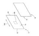
図1は、本発明の実施形態にかかる神経再生シート11,12の外観構成を示す斜視図である。図2は、コラーゲン糸状物21の不織布を作製する方法を示す模式図である。図3は、図1における領域105の拡大図である。図4は、神経再生シート11,12を用いて自律神経30を再生する方法を示す模式図である。[Explanation of drawings]
FIG. 1 is a perspective view showing an external configuration of
[神経再生シート11,12]
本実施形態に係る神経再生基材は、一対の神経再生シート11,12からなる。この神経再生シート11,12が、本発明における第1シートと第2シートにそれぞれ相当し、それぞれが本発明における神経再生基材用部品に相当する。[
The nerve regeneration substrate according to the present embodiment includes a pair of
図1に示されるように、神経再生シート11,12は、それぞれが薄肉の長方形のシートである。2枚の神経再生シート11,12は同じ形状である。神経再生シート11,12は、神経の断裂端を挟み込んで、その内側で神経の再生を促すものである。 As shown in FIG. 1, each of the
神経再生シート11,12は、コラーゲン糸状物21の不織布である。詳細に説明するに、湿式紡糸法によって、コラーゲン糸状物21を作製しながら巻取プレート20にコラーゲン糸状物21が巻き取られる。巻取プレート20は、神経再生シート11,12とほぼ同じ長方形の平板である。コラーゲン糸状物21の巻取りにおいて、図2(A)に示されるように、コラーゲン糸状物21が供給される向き101と巻取プレート20の回転軸線102とは直交している。 The
巻取プレート20における長辺方向103が回転軸線102と交わるように巻取プレート20が傾斜されて、回転軸線102に対して回転されることによって、コラーゲン糸状物21が巻取プレート20の長辺方向103と直交しない角度で巻取プレート20に巻き取られる。また、巻取プレート20は、回転されながらコラーゲン糸状物21に対して回転軸線102に沿って相対的に一方向へスライドされる。このスライド速度は、コラーゲン糸状物21の配列ピッチを考慮して設定される。これにより、巻取プレート20における長辺方向103の一端側から他端側へコラーゲン糸状物21が並列して巻取プレート20に巻き取られて、一定方向へ配列されたコラーゲン糸状物21の層が作製される。 The winding
次いで、図2(B)に示されるように、巻取プレート20における長辺方向103と回転軸線102との傾斜角度が変更されて、巻取プレート20が回転軸線102に対して回転される。これにより、コラーゲン糸状物21が巻取プレート20の長辺方向103と直交しない角度であって、先に巻き取られたコラーゲン糸状物21の配列方向とは異なる方向となって巻取プレート20に巻き取られる。また、巻取プレート20は、回転されながらコラーゲン糸状物21に対して回転軸線102に沿って相対的に一方向へスライドされる。これにより、巻取プレート20における長辺方向103の他端側から一端側へコラーゲン糸状物21が並列して巻取プレート20に巻き取られて、先に巻き取られたコラーゲン糸状物21に次のコラーゲン糸状物21の層が積層される。 Next, as shown in FIG. 2B, the inclination angle between the
前述されたように、巻取プレート20における長辺方向103と回転軸線102との傾斜角度がコラーゲン糸状物21が積層される毎に変更されて、巻取プレート20にコラーゲン糸状物21が巻き取られる。そして、最後に、図2(C)に示されるように、巻取プレート20における長辺方向103と回転軸線102とが直交されて、巻取プレート20が回転軸線102に対して回転される。これにより、コラーゲン糸状物21が巻取プレート20の長辺方向103に沿って巻取プレート20に巻き取られる。なお、巻取プレート20は、回転されながらコラーゲン糸状物21に対して回転軸線102に沿って相対的に一方向へスライドされる。これにより、巻取プレート20における長辺方向103に沿った方向へ配列されたコラーゲン糸状物21の層が巻取プレート20の最も外側に積層される。このコラーゲン糸状物21が本発明における生分解性繊維材に相当する。 As described above, the inclination angle between the
前述されたように巻取プレート20に巻き取られたコラーゲン糸状物21の巻取物を乾燥した後、巻取プレート20の周縁に沿って裁断すると、2枚のコラーゲン不織布が得られる。この2枚のコラーゲン不織布において、巻取プレート20の最も外側にある面が神経再生シート11,12の内面側の表層13,14となる。2枚のコラーゲン不織布は、必要に応じて所望のサイズの長方形に裁断される。 As described above, the
得られたコラーゲン不織布を、熱脱水架橋反応してから、さらにコラーゲン水溶液を含浸させて再び熱脱水架橋反応を行い、膜状の神経再生シート11,12が得られる。 The obtained collagen non-woven fabric is subjected to thermal dehydration crosslinking reaction, and further impregnated with a collagen aqueous solution and again subjected to thermal dehydration crosslinking reaction, whereby membrane-like
前述されたように、巻取プレート20の最も外側に積層されたコラーゲン糸状物21は、巻取プレート20における長辺方向103に沿っているので、図3に示されるように、神経再生シート11の内面側の表層13において、神経再生シート11の長辺方向104(第1方向)に沿ってコラーゲン糸状物21が配列されている。また、このコラーゲン糸状物21は、神経再生シート11の短辺15,16に渡って延出されている。なお、神経再生シート12について図示されていないが、同様に、内面側の表層14において長辺方向104に沿ってコラーゲン糸状物21が配列されている。 As described above, the
[神経再生シート11,12の使用方法]
以下、神経再生シート11,12の使用方法として、自律神経の断裂端同士をつなぎ合わせる方法が説明される。[How to use
Hereinafter, as a method of using the
まず、図4(A)に示されるように、神経再生シート11が自律神経30の断裂端31,32に対応させて配置される。このとき、神経再生シート11は、その表層13側における各短辺15,16付近に断裂端31,32がそれぞれ配置されて、断裂端31,32が神経再生シート11の長辺方向104へ離間された状態とされる。神経再生シート11における各短辺15,16付近が、本発明における第1位置及び第2位置にそれぞれ相当する。 First, as shown in FIG. 4A, the
つづいて、図4(B)に示されるように、自律神経30の断裂端31,32を神経再生シート11との間に挟み込むように、神経再生シート11に対して神経再生シート12が重ね合わされる。このとき、神経再生シート12の表層14が神経再生シート11の表層13と対向し、かつ神経再生シート11と神経再生シート12との長辺同士、及び短辺同士が対応される。そして、神経再生シート11,12の長辺に沿って2枚の神経再生シート11,12が縫合される(図4(B)における二点鎖線で示される箇所が縫合箇所である。)。これにより、神経再生シート11,12の内側へ周辺組織などが進入することが防止される。 Next, as shown in FIG. 4B, the
前述された状態で放置されると、自律神経30の断裂端31,32から神経が再生して、断裂端31,32間の神経が回復する。前述されたように、神経再生シート11,12の表層13,14には、長辺方向104に沿ってコラーゲン糸状物21が配列されているので、そのコラーゲン糸状物21に沿って断裂端31,32から再生された神経が延びる。つまり、複数のコラーゲン糸状物21の間を誘導経路として再生された神経が延びる。 When left in the state described above, the nerve is regenerated from the torn ends 31 and 32 of the
[本実施形態の作用効果]
本実施形態によれば、再生すべき自律神経30を挟み込む一対の神経再生シート11,12の表層13,14に、自律神経30の断裂端31,32が配置される短辺15,16に渡って延びるコラーゲン糸状物21が配列して配置されているので、自律神経30における比較的細い神経線維を効率よく正しい方向へ再生させることができる。[Operational effects of this embodiment]
According to the present embodiment, the surface layers 13 and 14 of the pair of
また、神経再生シート11,12は、コラーゲン糸状物21からなるので、生体内において分解された後に吸収される。また、コラーゲン糸状物21は神経細胞の接着性に優れる。さらに、神経再生シート11,12は、コラーゲン糸状物21の不織布なので、各表層13,14にコラーゲン糸状物21を並列して配置させることが容易である。 Moreover, since the
11,12・・・神経再生シート(第1シート、第2シート、神経再生基材用部品)
13,14・・・表層
15,16・・・短辺(第1位置、第2位置)
21・・・コラーゲン糸状物(生分解性繊維材)
30・・・自律神経
31,32・・・断裂端11, 12 ... nerve regeneration sheet (first sheet, second sheet, parts for nerve regeneration substrate)
13, 14 ... surface layers 15, 16 ... short sides (first position, second position)
21 ... Collagen filament (biodegradable fiber material)
30 ...
Claims (5)
Translated fromJapanese上記第1シート及び上記第2シートのうち少なくとも一方において他方と対向する側の表層に設けられて、当該表層において神経の断裂端がそれぞれ配置される第1位置及び第2位置に渡って延出された生分解性繊維材と、を具備する神経再生基材。It is made of a biodegradable material,and is stacked and laminated , so that at least a pair of a first sheet and a second sheet that sandwich a nerve to be regenerated,
At least one of the first sheet and the second sheet is provided on a surface layer facing the other, and extends across a first position and a second position at which the nerve tear ends are respectively disposed on the surface layer. A nerve regeneration substrate comprising the biodegradable fiber material.
Priority Applications (1)
| Application Number | Priority Date | Filing Date | Title |
|---|---|---|---|
| JP2008275982AJP5386929B2 (en) | 2008-10-27 | 2008-10-27 | Nerve regeneration substrate and parts for nerve regeneration substrate |
Applications Claiming Priority (1)
| Application Number | Priority Date | Filing Date | Title |
|---|---|---|---|
| JP2008275982AJP5386929B2 (en) | 2008-10-27 | 2008-10-27 | Nerve regeneration substrate and parts for nerve regeneration substrate |
Publications (2)
| Publication Number | Publication Date |
|---|---|
| JP2010099419A JP2010099419A (en) | 2010-05-06 |
| JP5386929B2true JP5386929B2 (en) | 2014-01-15 |
Family
ID=42290591
Family Applications (1)
| Application Number | Title | Priority Date | Filing Date |
|---|---|---|---|
| JP2008275982AActiveJP5386929B2 (en) | 2008-10-27 | 2008-10-27 | Nerve regeneration substrate and parts for nerve regeneration substrate |
Country Status (1)
| Country | Link |
|---|---|
| JP (1) | JP5386929B2 (en) |
Families Citing this family (2)
| Publication number | Priority date | Publication date | Assignee | Title |
|---|---|---|---|---|
| JP5453776B2 (en)* | 2008-11-14 | 2014-03-26 | ニプロ株式会社 | Nerve regeneration substrate |
| JP5453774B2 (en)* | 2008-11-14 | 2014-03-26 | ニプロ株式会社 | Nerve regeneration substrate and parts for nerve regeneration substrate |
Family Cites Families (6)
| Publication number | Priority date | Publication date | Assignee | Title |
|---|---|---|---|---|
| JPS63119754A (en)* | 1986-11-10 | 1988-05-24 | 東京大学長 | Artificial element having cell growth specificity |
| JPH0669487B2 (en)* | 1991-02-15 | 1994-09-07 | 東京大学長 | Method for promoting and controlling biological cell growth and functional differentiation |
| JP3966045B2 (en)* | 2002-04-03 | 2007-08-29 | ニプロ株式会社 | Collagen nonwoven fabric, its production method, its treatment method and apparatus |
| JP4411834B2 (en)* | 2002-10-31 | 2010-02-10 | ニプロ株式会社 | Biodegradable substrate, tissue regeneration prosthesis, and cultured tissue |
| CA2640601C (en)* | 2006-01-27 | 2015-12-29 | The Regents Of The University Of California | Biomimetic fibrous polymer scaffolds |
| JP5157139B2 (en)* | 2006-11-28 | 2013-03-06 | 大日本印刷株式会社 | Cell transplant material |
- 2008
- 2008-10-27JPJP2008275982Apatent/JP5386929B2/enactiveActive
Also Published As
| Publication number | Publication date |
|---|---|
| JP2010099419A (en) | 2010-05-06 |
Similar Documents
| Publication | Publication Date | Title |
|---|---|---|
| US7718556B2 (en) | Medical film | |
| JP4605985B2 (en) | Nerve regeneration induction tube | |
| JP2004148014A (en) | Biodegradable base material and prosthesis for anagenesis, and cultured tissue | |
| JP5453776B2 (en) | Nerve regeneration substrate | |
| JP4581318B2 (en) | Biodegradable cylindrical body and biological tissue or organ regeneration device using the same | |
| CN108601862B (en) | Filamentous graft implants and methods of making and using same | |
| JP5320726B2 (en) | Method for producing collagen fiber bundle | |
| JP5386929B2 (en) | Nerve regeneration substrate and parts for nerve regeneration substrate | |
| JP4840136B2 (en) | Adhesion prevention kit, method for producing adhesion prevention kit, and adhesion prevention method | |
| JP4554916B2 (en) | Medical film | |
| JP5453774B2 (en) | Nerve regeneration substrate and parts for nerve regeneration substrate | |
| JP2003062063A (en) | Material for preventing synechia | |
| JP4569543B2 (en) | Precursor for tissue regeneration device with swellable rod | |
| JP5089688B2 (en) | Collagen tube | |
| JP2000237300A (en) | Hollow yarn with fine diameter, its hollow yarn bundle and manufacture thereof | |
| JP5703804B2 (en) | Tissue regeneration device precursor and method for producing the same | |
| JP5563182B2 (en) | Tissue regeneration device precursor with releasable fixation means | |
| JP5017936B2 (en) | Precursor of tissue regeneration device with fixation means in the excision region | |
| JP4620952B2 (en) | Base material for urethral tissue regeneration and method for urethral tissue regeneration | |
| JP2024020670A (en) | Growth induction member and tissue regeneration instrument | |
| WO2022138956A1 (en) | Biodegradable or bioabsorbable tubular body and manufacturing method thereof | |
| JP2012250069A (en) | Precursor for tissue regeneration instrument provided with cancelable fixing means | |
| HK1086204B (en) | Medical film | |
| JPWO2019189835A1 (en) | Suture aid |
Legal Events
| Date | Code | Title | Description |
|---|---|---|---|
| A621 | Written request for application examination | Free format text:JAPANESE INTERMEDIATE CODE: A621 Effective date:20110608 | |
| A131 | Notification of reasons for refusal | Free format text:JAPANESE INTERMEDIATE CODE: A131 Effective date:20130226 | |
| A521 | Request for written amendment filed | Free format text:JAPANESE INTERMEDIATE CODE: A523 Effective date:20130430 | |
| TRDD | Decision of grant or rejection written | ||
| A01 | Written decision to grant a patent or to grant a registration (utility model) | Free format text:JAPANESE INTERMEDIATE CODE: A01 Effective date:20130910 | |
| A61 | First payment of annual fees (during grant procedure) | Free format text:JAPANESE INTERMEDIATE CODE: A61 Effective date:20130923 | |
| R150 | Certificate of patent or registration of utility model | Ref document number:5386929 Country of ref document:JP Free format text:JAPANESE INTERMEDIATE CODE: R150 Free format text:JAPANESE INTERMEDIATE CODE: R150 | |
| R250 | Receipt of annual fees | Free format text:JAPANESE INTERMEDIATE CODE: R250 | |
| R250 | Receipt of annual fees | Free format text:JAPANESE INTERMEDIATE CODE: R250 | |
| R250 | Receipt of annual fees | Free format text:JAPANESE INTERMEDIATE CODE: R250 | |
| R250 | Receipt of annual fees | Free format text:JAPANESE INTERMEDIATE CODE: R250 |