JP5386673B2 - Puncture needle cartridge and puncture device - Google Patents
Puncture needle cartridge and puncture deviceDownload PDFInfo
- Publication number
- JP5386673B2 JP5386673B2JP2010515922AJP2010515922AJP5386673B2JP 5386673 B2JP5386673 B2JP 5386673B2JP 2010515922 AJP2010515922 AJP 2010515922AJP 2010515922 AJP2010515922 AJP 2010515922AJP 5386673 B2JP5386673 B2JP 5386673B2
- Authority
- JP
- Japan
- Prior art keywords
- puncture
- needle body
- needle
- casing
- end side
- Prior art date
- Legal status (The legal status is an assumption and is not a legal conclusion. Google has not performed a legal analysis and makes no representation as to the accuracy of the status listed.)
- Active
Links
Images


Classifications
- A—HUMAN NECESSITIES
- A61—MEDICAL OR VETERINARY SCIENCE; HYGIENE
- A61B—DIAGNOSIS; SURGERY; IDENTIFICATION
- A61B5/00—Measuring for diagnostic purposes; Identification of persons
- A61B5/15—Devices for taking samples of blood
- A61B5/150007—Details
- A61B5/150374—Details of piercing elements or protective means for preventing accidental injuries by such piercing elements
- A61B5/150381—Design of piercing elements
- A61B5/150442—Blade-like piercing elements, e.g. blades, cutters, knives, for cutting the skin
- A61B5/150458—Specific blade design, e.g. for improved cutting and penetration characteristics
- A—HUMAN NECESSITIES
- A61—MEDICAL OR VETERINARY SCIENCE; HYGIENE
- A61B—DIAGNOSIS; SURGERY; IDENTIFICATION
- A61B5/00—Measuring for diagnostic purposes; Identification of persons
- A61B5/15—Devices for taking samples of blood
- A61B5/150007—Details
- A61B5/150015—Source of blood
- A61B5/150022—Source of blood for capillary blood or interstitial fluid
- A—HUMAN NECESSITIES
- A61—MEDICAL OR VETERINARY SCIENCE; HYGIENE
- A61B—DIAGNOSIS; SURGERY; IDENTIFICATION
- A61B5/00—Measuring for diagnostic purposes; Identification of persons
- A61B5/15—Devices for taking samples of blood
- A61B5/150007—Details
- A61B5/150206—Construction or design features not otherwise provided for; manufacturing or production; packages; sterilisation of piercing element, piercing device or sampling device
- A61B5/150274—Manufacture or production processes or steps for blood sampling devices
- A61B5/150282—Manufacture or production processes or steps for blood sampling devices for piercing elements, e.g. blade, lancet, canula, needle
- A—HUMAN NECESSITIES
- A61—MEDICAL OR VETERINARY SCIENCE; HYGIENE
- A61B—DIAGNOSIS; SURGERY; IDENTIFICATION
- A61B5/00—Measuring for diagnostic purposes; Identification of persons
- A61B5/15—Devices for taking samples of blood
- A61B5/151—Devices specially adapted for taking samples of capillary blood, e.g. by lancets, needles or blades
- A61B5/15101—Details
- A61B5/15103—Piercing procedure
- A61B5/15107—Piercing being assisted by a triggering mechanism
- A61B5/15111—Semi-automatically triggered, e.g. at the end of the cocking procedure, for instance by biasing the main drive spring or when reaching sufficient contact pressure, the piercing device is automatically triggered without any deliberate action by the user
- A—HUMAN NECESSITIES
- A61—MEDICAL OR VETERINARY SCIENCE; HYGIENE
- A61B—DIAGNOSIS; SURGERY; IDENTIFICATION
- A61B5/00—Measuring for diagnostic purposes; Identification of persons
- A61B5/15—Devices for taking samples of blood
- A61B5/151—Devices specially adapted for taking samples of capillary blood, e.g. by lancets, needles or blades
- A61B5/15101—Details
- A61B5/15103—Piercing procedure
- A61B5/15107—Piercing being assisted by a triggering mechanism
- A61B5/15113—Manually triggered, i.e. the triggering requires a deliberate action by the user such as pressing a drive button
- A—HUMAN NECESSITIES
- A61—MEDICAL OR VETERINARY SCIENCE; HYGIENE
- A61B—DIAGNOSIS; SURGERY; IDENTIFICATION
- A61B5/00—Measuring for diagnostic purposes; Identification of persons
- A61B5/15—Devices for taking samples of blood
- A61B5/151—Devices specially adapted for taking samples of capillary blood, e.g. by lancets, needles or blades
- A61B5/15101—Details
- A61B5/15115—Driving means for propelling the piercing element to pierce the skin, e.g. comprising mechanisms based on shape memory alloys, magnetism, solenoids, piezoelectric effect, biased elements, resilient elements, vacuum or compressed fluids
- A61B5/15117—Driving means for propelling the piercing element to pierce the skin, e.g. comprising mechanisms based on shape memory alloys, magnetism, solenoids, piezoelectric effect, biased elements, resilient elements, vacuum or compressed fluids comprising biased elements, resilient elements or a spring, e.g. a helical spring, leaf spring, or elastic strap
- A—HUMAN NECESSITIES
- A61—MEDICAL OR VETERINARY SCIENCE; HYGIENE
- A61B—DIAGNOSIS; SURGERY; IDENTIFICATION
- A61B5/00—Measuring for diagnostic purposes; Identification of persons
- A61B5/15—Devices for taking samples of blood
- A61B5/151—Devices specially adapted for taking samples of capillary blood, e.g. by lancets, needles or blades
- A61B5/15101—Details
- A61B5/15126—Means for controlling the lancing movement, e.g. 2D- or 3D-shaped elements, tooth-shaped elements or sliding guides
- A61B5/1513—Means for controlling the lancing movement, e.g. 2D- or 3D-shaped elements, tooth-shaped elements or sliding guides comprising linear sliding guides
- A—HUMAN NECESSITIES
- A61—MEDICAL OR VETERINARY SCIENCE; HYGIENE
- A61B—DIAGNOSIS; SURGERY; IDENTIFICATION
- A61B5/00—Measuring for diagnostic purposes; Identification of persons
- A61B5/15—Devices for taking samples of blood
- A61B5/151—Devices specially adapted for taking samples of capillary blood, e.g. by lancets, needles or blades
- A61B5/15186—Devices loaded with a single lancet, i.e. a single lancet with or without a casing is loaded into a reusable drive device and then discarded after use; drive devices reloadable for multiple use
- A61B5/15188—Constructional features of reusable driving devices
- A61B5/1519—Constructional features of reusable driving devices comprising driving means, e.g. a spring, for propelling the piercing unit
- A—HUMAN NECESSITIES
- A61—MEDICAL OR VETERINARY SCIENCE; HYGIENE
- A61B—DIAGNOSIS; SURGERY; IDENTIFICATION
- A61B5/00—Measuring for diagnostic purposes; Identification of persons
- A61B5/15—Devices for taking samples of blood
- A61B5/151—Devices specially adapted for taking samples of capillary blood, e.g. by lancets, needles or blades
- A61B5/15186—Devices loaded with a single lancet, i.e. a single lancet with or without a casing is loaded into a reusable drive device and then discarded after use; drive devices reloadable for multiple use
- A61B5/15188—Constructional features of reusable driving devices
- A61B5/15192—Constructional features of reusable driving devices comprising driving means, e.g. a spring, for retracting the lancet unit into the driving device housing
- A61B5/15194—Constructional features of reusable driving devices comprising driving means, e.g. a spring, for retracting the lancet unit into the driving device housing fully automatically retracted, i.e. the retraction does not require a deliberate action by the user, e.g. by terminating the contact with the patient's skin
Landscapes
- Health & Medical Sciences (AREA)
- Life Sciences & Earth Sciences (AREA)
- Engineering & Computer Science (AREA)
- Heart & Thoracic Surgery (AREA)
- Molecular Biology (AREA)
- Pathology (AREA)
- Physics & Mathematics (AREA)
- Biomedical Technology (AREA)
- Hematology (AREA)
- Medical Informatics (AREA)
- Biophysics (AREA)
- Surgery (AREA)
- Animal Behavior & Ethology (AREA)
- General Health & Medical Sciences (AREA)
- Public Health (AREA)
- Veterinary Medicine (AREA)
- Manufacturing & Machinery (AREA)
- Measurement Of The Respiration, Hearing Ability, Form, And Blood Characteristics Of Living Organisms (AREA)
Description
Translated fromJapanese本発明は、穿刺器具本体に装着して穿刺を行うための穿刺針カートリッジ及び穿刺装置に関する。 The present invention relates to a puncture needle cartridge and a puncture device that are attached to a puncture device body to perform puncture.
穿刺器具は、指先等の組織を穿刺する穿刺針を備えており、例えば血糖値測定時の微量採血等に用いられる。穿刺針は、感染防止のために使用毎の交換が前提とされていることから、穿刺針を取替え可能な穿刺器具が従来から知られている。 The puncture device includes a puncture needle that punctures a tissue such as a fingertip, and is used, for example, for collecting a small amount of blood during blood glucose measurement. Since the puncture needle is premised on exchange for each use in order to prevent infection, a puncture device that can replace the puncture needle is conventionally known.
例えば、特許文献1に開示された穿刺具は、プランジャの先端に穿刺針保持部を備えており、この穿刺針保持部に穿刺針カートリッジが着脱可能に嵌合される。穿刺針カートリッジは、穿刺針が取り付けられた本体部がカバー内に摺動可能に設けられており、プランジャの作用により本体部が移動し、穿刺を行うことができる。 For example, the puncture device disclosed in
ところが、従来の穿刺針カートリッジは、穿刺針がカバーから不意に飛び出すおそれがあることから、使用前は穿刺針をキャップ等で保護する必要がある一方、使用後は廃棄のために穿刺針に再びキャップを装着したり、穿刺針をカバー内に引き戻す機構を穿刺具に設ける必要があり、作業面やコスト面で改良の余地があった。 However, in the conventional puncture needle cartridge, since the puncture needle may unexpectedly jump out of the cover, it is necessary to protect the puncture needle with a cap or the like before use. It is necessary to provide the puncture tool with a mechanism for attaching a cap or pulling the puncture needle back into the cover, and there is room for improvement in terms of work and cost.
そこで、本発明は、低コストで量産性に優れ、使用者が安全かつ簡便に穿刺することができる穿刺針カートリッジ及び穿刺装置の提供を目的とする。 Therefore, an object of the present invention is to provide a puncture needle cartridge and a puncture device that are low in cost, excellent in mass productivity, and safe and simple for a user to puncture.
本発明の前記目的は、穿刺器具本体に着脱可能に装着されて穿刺器具を構成する穿刺針カートリッジであって、穿刺部を有する針本体と、前記針本体を収容し、前記針本体の前方および後方にそれぞれ開口を有するケーシングとを備え、前記針本体は、前記穿刺部の先端が前記ケーシング内に退避した退避位置と、前記穿刺器具本体から押圧力を受けて前記穿刺部の先端が前記ケーシングから外方に突出する突出位置との間で、進退可能に配置されており、前記突出位置にある前記針本体を前記退避位置に付勢する付勢手段を備える穿刺針カートリッジにおいて、前記付勢手段は、前記針本体の両側にそれぞれ配置された一対の可撓片を備え、前記各可撓片は、一端側が前記ケーシング内に固定され、他端側が前記針本体と係合するように配置されており、前記針本体は、先細となるように形成された傾斜面からなる一対の係合部を備え、前記退避位置から前記突出位置に向けた前記針本体の移動により、前記各可撓片は、他端側が前記各係合部とそれぞれ摺接して、前記針本体の移動方向に沿ってたわみ変形することを特徴とする穿刺針カートリッジにより達成される。
The object of the present invention is a puncture needle cartridge which is detachably attached to a puncture device body and constitutes a puncture device, comprising a needle body having a puncture portion, the needle body, the front of the needle body and The needle body has a retracted position in which the distal end of the puncture portion is retracted into the casing, and the distal end of the puncture portion receives the pressing force from the puncture device body. In thepuncture needle cartridge, provided with a biasing means that is disposed so as to be able to advance and retreat between a protruding position protruding outward from the protruding position and biasing the needle body at the protruding position to the retracted position. The means includes a pair of flexible pieces respectively arranged on both sides of the needle body, and each flexible piece is arranged so that one end side is fixed in the casing and the other end side is engaged with the needle body. The needle body includes a pair of engaging portions formed of inclined surfaces formed to be tapered, and each of the flexible bodies is moved by moving the needle body from the retracted position toward the protruding position. The piece is achieved bya puncture needle cartridge characterized in that the other end side is slidably contacted with each of the engaging portions and is bent and deformed along the moving direction of the needle body .
また、本発明の前記目的は、穿刺部を有する針本体と、前記針本体を収容し、前記針本体の前方および後方にそれぞれ開口を有するケーシングとを備え、前記針本体は、前記ケーシングの後部開口を介して押圧可能に構成され、前記穿刺部の先端が前記ケーシング内に退避した退避位置と、押圧により前記穿刺部の先端が前記ケーシングから外方に突出する突出位置との間で、進退可能に配置されており、前記突出位置にある前記針本体を前記退避位置に付勢する付勢手段を備える穿刺装置において、前記付勢手段は、前記針本体の両側にそれぞれ配置された一対の可撓片を備え、前記各可撓片は、一端側が前記ケーシング内に固定され、他端側が前記針本体と係合するように配置されており、前記針本体は、先細となるように形成された傾斜面からなる一対の係合部を備え、前記退避位置から前記突出位置に向けた前記針本体の移動により、前記各可撓片は、他端側が前記各係合部とそれぞれ摺接して、前記針本体の移動方向に沿ってたわみ変形することを特徴とする穿刺装置により達成される。In addition, the object of the present invention is provided with a needle body having a puncture portion, and a casing that accommodates the needle body and has openings in front and rear of the needle body, respectively, and the needle body is a rear portion of the casing. It is configured to be able to be pressed through an opening, and is advanced and retracted between a retracted position in which the tip of the puncture part is retracted into the casing and a protruding position in which the tip of the puncture part protrudes outward from the casing by the pressing. In the puncture device that is arranged so as to be capable of energizing the needle main body at the protruding position to the retracted position, the energizing means are a pair of needles arranged on both sides of the needle main body, respectively. Each flexible piece includes a flexible piece, one end side is fixed in the casing, the other end side is arranged to engage with the needle body, and the needle body is formed to be tapered. Tilted Each of the flexible pieces is in sliding contact with each of the engaging portions by the movement of the needle main body from the retracted position toward the protruding position. This is achieved by a puncture device characterized by bending deformation along the moving direction of the needle body.
また、本発明の前記目的は、穿刺器具本体に着脱可能に装着されて穿刺器具を構成する穿刺針カートリッジであって、穿刺部を有する針本体と、前記針本体を収容し、前記針本体の前方および後方にそれぞれ開口を有するケーシングとを備え、前記針本体は、前記穿刺部の先端が前記ケーシング内に退避した退避位置と、前記穿刺器具本体から押圧力を受けて前記穿刺部の先端が前記ケーシングから外方に突出する突出位置との間で、進退可能に配置されており、前記突出位置にある前記針本体を前記退避位置に付勢する付勢手段を備える穿刺針カートリッジにおいて、前記付勢手段は、前記針本体の両側にそれぞれ配置された一対の可撓片を備え、前記各可撓片は、一端側が前記ケーシング内に固定され、他端側が前記針本体と係合するように配置されており、前記針本体は、先細となるように形成された傾斜面からなる一対の係合部を備え、一対の前記可撓片の先端に設けられた平面視円弧状の当接部が、平面視直線状の前記係合部にそれぞれ当接することを特徴とする穿刺針カートリッジにより達成される。Further, the object of the present invention is a puncture needle cartridge which is detachably mounted on a puncture device body and constitutes a puncture device, which includes a needle body having a puncture portion, the needle body, The needle body has a retracted position in which the distal end of the puncture portion is retracted into the casing, and the distal end of the puncture portion receives a pressing force from the puncture device body. In the puncture needle cartridge, which is disposed so as to be able to advance and retreat between a protruding position protruding outward from the casing, and includes a biasing means for biasing the needle body at the protruding position to the retracted position, The biasing means includes a pair of flexible pieces arranged on both sides of the needle body, and each flexible piece has one end fixed in the casing and the other end engaged with the needle body. The needle body is provided with a pair of engaging portions each having an inclined surface formed so as to be tapered, and has an arcuate contact in a plan view provided at the distal ends of the pair of flexible pieces. This is achieved by a puncture needle cartridge in which the portions abut on the engaging portions that are linear in a plan view.
また、本発明の前記目的は、穿刺部を有する針本体と、前記針本体を収容し、前記針本体の前方および後方にそれぞれ開口を有するケーシングとを備え、前記針本体は、前記ケーシングの後部開口を介して押圧可能に構成され、前記穿刺部の先端が前記ケーシング内に退避した退避位置と、押圧により前記穿刺部の先端が前記ケーシングから外方に突出する突出位置との間で、進退可能に配置されており、前記突出位置にある前記針本体を前記退避位置に付勢する付勢手段を備える穿刺装置において、前記付勢手段は、前記針本体の両側にそれぞれ配置された一対の可撓片を備え、前記各可撓片は、一端側が前記ケーシング内に固定され、他端側が前記針本体と係合するように配置されており、前記針本体は、先細となるように形成された傾斜面からなる一対の係合部を備え、一対の前記可撓片の先端に設けられた平面視円弧状の当接部が、平面視直線状の前記係合部にそれぞれ当接することを特徴とする穿刺装置により達成される。In addition, the object of the present invention is provided with a needle body having a puncture portion, and a casing that accommodates the needle body and has openings in front and rear of the needle body, respectively, and the needle body is a rear portion of the casing. It is configured to be able to be pressed through an opening, and is advanced and retracted between a retracted position in which the tip of the puncture part is retracted into the casing and a protruding position in which the tip of the puncture part protrudes outward from the casing by the pressing. In the puncture device that is arranged so as to be capable of energizing the needle main body at the protruding position to the retracted position, the energizing means are a pair of needles arranged on both sides of the needle main body, respectively. Each flexible piece includes a flexible piece, one end side is fixed in the casing, the other end side is arranged to engage with the needle body, and the needle body is formed to be tapered. Tilted A pair of engaging portions each having a surface are provided, and the contact portions having a circular arc shape in plan view provided at the tips of the pair of flexible pieces respectively contact the engaging portions having a linear shape in plan view. Achieved by the lancing device.
本発明の穿刺針カートリッジ及び穿刺装置によれば、低コストで量産性に優れ、使用者が安全かつ簡便に穿刺することができる。 According to the puncture needle cartridge and the puncture device of the present invention, the puncture needle cartridge and the puncture device are excellent in mass productivity at low cost, and the user can puncture safely and easily.
以下、本発明の実施の形態について、添付図面を参照して説明する。図1は、本発明の一実施形態に係る穿刺針カートリッジを備えた穿刺器具の断面図である。図1に示すように、穿刺器具1は、穿刺器具本体10と、この穿刺器具本体10に着脱可能に装着される穿刺針カートリッジ20とを備えている。なお、以下の各図面において、同様の構成要素には同一の符号を付して、詳細な説明を省略する。Hereinafter, embodiments of the present invention will be described with reference to the accompanying drawings. FIG. 1 is a cross-sectional view of a puncture device including a puncture needle cartridge according to an embodiment of the present invention. As shown in FIG. 1, the
穿刺器具本体10は、ハウジング11と、ハウジング11内に収容されたプランジャ12とを備えており、ハウジング11の前側に、穿刺針カートリッジ20を装着する装着部11aを備えている。なお、図1は、ハウジング11の上蓋を取り除いた断面を示している。 The puncture device
装着部11aは、後端側がハウジング11と一体化されて前端側が可撓性を有する一対の挟持片111,112から構成されており、穿刺針カートリッジ20を前方から挟持片111,112の間に挿入して、挟持片111,112の間隔を押し拡げることにより、穿刺針カートリッジ20の外表面に形成されたリブ20aが挟持片111,112の係合溝111a,112aに係合し、挟持片111,112の弾性力により穿刺針カートリッジ20が挟持される。穿刺器具本体10に対する穿刺針カートリッジ20の装着及び脱着は、本実施形態のように前方から行う以外に、上下方向(図1の図面と直交する方向)から行うように構成することも可能である。 The
プランジャ12は、直棒状本体121の先端側に押圧体122が設けられ、後端側に引出体123が設けられており、押圧体122とハウジング11の後端内面113との間に外嵌されたコイルばね124により、先端方向に付勢される。引出体123は、ハウジング11の後方に突出しており、この突出部分を摘んで引くことにより、プランジャ12を後方に移動させることができる。 The
押圧体122は、先端に形成された駆動突部122aと、両側面に形成された係合突部122b,122cとを備えている。駆動突部122aは、プランジャ12の前方への移動に伴い、穿刺針カートリッジ20に押圧力を作用させる。また、係合突部122b,122cは、プランジャ12の後方への移動に伴い、ハウジング11の内周面から突出する保持部11b,11cとそれぞれ係合する。 The
ハウジング11の上蓋(図示せず)には、可撓性部材からなる穿刺ボタン125が取り付けられている。この穿刺ボタン125の下部には、帯状部材の両端が下方に折り曲げられた解除片125aが設けられており、穿刺ボタン125を指などで押圧すると、穿刺ボタン125の撓みにより、解除片125aの両端が保持部11b,11cを下方に押圧して係合突部122b,122cとの係合を解除する一方、穿刺ボタン125から指を離すと、穿刺ボタン125及び解除片125aが元の位置に戻るように構成されている。図1においては、ハウジング11の上蓋を取り除いた断面で示しているため、穿刺ボタン125及び解除片125aを破線で図示している。 A
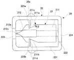
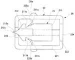
図2は、図1に示す穿刺針カートリッジ20の拡大断面図である。図2に示すように、穿刺針カートリッジ20は、針本体21と、この針本体21が収容される筐体状のケーシング22とを備えている。図2は、ケーシング22の上蓋を取り外した状態を示している。 FIG. 2 is an enlarged cross-sectional view of the
針本体21は、台座部211の前側上部に支持部212を設けて構成されており、図3に側面図で示すように、台座部211の下部中央から下方に突出するガイド突起213を有している。ガイド突起213は、ケーシング22の底面221に前後方向へ延びるように形成されたガイド溝222に係合しており、針本体21は、ケーシング22の上下内面と摺動しながら、ガイド溝222に沿って進退可能に配置されている。 The needle
台座部211は、前方に向けて先細になるように形成された傾斜面からなる一対の係合部211a,211bが、支持部212の軸線を挟んで左右両側にそれぞれ形成されている。本実施形態においては、各係合部211a,211bが、台座部211の左右両側の中央付近を一部切り欠いた状態に形成されており、これによって、各係合部211a,211bの先端には、それぞれ段部211c,211dが形成されている。 The
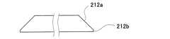
また、支持部212の穿刺部212aは、図4に示すように、断面積が先端212cから後方に向けて単調増加及び単調減少を交互に繰り返すように形成されており、穿刺時の痛みを軽減可能な形状とされている。この穿刺部212aの軸線に垂直な断面の形状は、図5に示すように概ね台形状であり、台形の底辺に一定幅の立上り部212bが形成されて、厳密には六角形状とされている。この立上り部212bは、針本体21を射出成形や押出成形などにより形成する場合に、上型と下型との合わせ面を台座部211と支持部212との境界面(図3の2点鎖線)とすることにより、射出材料が立上り部212bを経て支持部212の全体に行き渡り易くなり、先端212cを先鋭化することができる。但し、穿刺部212aの断面形状は、略台形状以外に、例えば、三角形状やその他の多角形状であってもよく、先端が穿刺可能な程度に尖ったものであれば特に限定されない。 Further, as shown in FIG. 4, the
支持部212の材料は、生体適合性材料からなることが好ましい。具体的には、ポリ乳酸やポリグリコール酸などの生分解性ポリマ(生分解性の共重合体を含む)を好ましく例示することができるが、これに限定されるものではなく、ポリ塩化ビニルやポリエチレングリコールなどの高分子ポリマ、セルロースやでんぷんなどの生体高分子、或いは、コラーゲンやゼラチンなどの蛋白質、セラミックやカーボンなどの生体適合性無機材料などを使用することができる。また、ステンレス系、コバルト系、チタン系などの生体親和性を有する金属材料で支持部212を形成することもできる。台座部211の材料は、本実施形態のように支持部212と一体成形する場合には、支持部212と同じ材料となるが、台座部211及び支持部212の材料がそれぞれ異なるものであってもよい。 The material of the
また、ケーシング22は、収容された針本体21の前方及び後方とそれぞれ対向する位置に、開口223,224が形成されており、図1に示す穿刺器具本体10のプランジャ12が前方に移動すると、押圧体122の駆動突部122aが台座部211の後端面を押圧し、支持部212の先端212cが開口223から突出する。前側の開口223は、図6に示すように、支持部212の穿刺部212aがケーシング22内を進退する際に先端212cが損傷しないように、開口上縁に切欠部223aが形成されている。 Further, the
ケーシング22の内壁面には、互いに対向する位置に突出する一対の可撓片225a,225bが設けられている。この可撓片225a,225bは、ケーシング22と一体的に成形された弾性体であり、図1に示すように、突出方向の先端が係合部211a,211bの最細部と当接するように、突出長さが調整されている。可撓片225a,225bの形状は、本実施形態では帯状(平板状)としているが、弾性変形によりたわみを生じる形状であれば特に限定されず、湾曲状や線状など他の形状であってもよい。 A pair of
ケーシング22は、弾性を有する材料により形成することが好ましく、例えば、台座部211や支持部212と同じ材料から形成することができる。穿刺針カートリッジ20を構成する針本体21及びケーシング22は、上記のように、生体適合性材料により作製することができる。この生体適合性材料としては、例えば、高分子ポリマ、生体高分子、蛋白質、および生体適合性無機材料が含まれる。 The
高分子ポリマとしては、医療用に使用可能なものが好ましく使用可能であり、例えば、ポリ塩化ビニル,ポリエチレングリコール,パリレン,ポリエチレン,ポリプロピレン,シリコーン,ポリイソプレン,ポリメチルメタクリレート,フッ素樹脂,ポリエーテルイミド,ポリエチレンオキサイド,ポリエチレンテレフタレート,ポリエチレンサクシネート,ポリブチレンテレフタレート,ポリブチレンサクシネート,ポリブチレンサクシネートカーボネート,ポリフェニレンオキサイド,ポリフェニレンサルファイド,ポリホルムアルデヒド,ポリアンヒドリド,ポリアミド(6ナイロン、66ナイロン),ポリブタジエン,ポリ酢酸ビニル,ポリビニルアルコール,ポリビニルピロリドン,ポリエステルアミド,ポリメタクリル酸メチル,ポリアクリロニトリル,ポリサルホン,ポリエーテルサルホン,ABS樹脂,ポリカーボネート,ポリウレタン(ポリエーテルウレタン、ポリエステルウレタン、ポリエーテルウレタン尿素),ポリ塩化ビニリデン,ポリスチレン,ポリアセタール,ポリブタジエン,エチレン酢酸ビニル共重合体,エチレンビニルアルコール共重合体,エチレンプロピレン共重合体,ポリヒドロキシエチルメタクリレート,ポリヒイドロブチレート,ポリオルトエステル,ポリ乳酸,ポリグリコール,ポリカプロラクトン,ポリ乳酸共重合体,ポリグリコール酸・グリコール共重合体,ポリカプロノラクトン共重合体,ポリジオキサノン,パーフルオロエチレン−プロピレン共重合体,シアノアクリレート重合体,ポリブチルシアノアクリレート,ポリアリルエーテルケトン,エポキシ樹脂,ポリエステル樹脂,ポリイミド,フェノール樹脂、アクリル樹脂が挙げられる。 As the polymer, those usable for medical use can be preferably used. For example, polyvinyl chloride, polyethylene glycol, parylene, polyethylene, polypropylene, silicone, polyisoprene, polymethyl methacrylate, fluororesin, polyetherimide , Polyethylene oxide, polyethylene terephthalate, polyethylene succinate, polybutylene terephthalate, polybutylene succinate, polybutylene succinate carbonate, polyphenylene oxide, polyphenylene sulfide, polyformaldehyde, polyanhydride, polyamide (6 nylon, 66 nylon), polybutadiene, poly Vinyl acetate, polyvinyl alcohol, polyvinyl pyrrolidone, polyester amide, polymethyl methacrylate Polyacrylonitrile, polysulfone, polyethersulfone, ABS resin, polycarbonate, polyurethane (polyether urethane, polyester urethane, polyether urethane urea), polyvinylidene chloride, polystyrene, polyacetal, polybutadiene, ethylene vinyl acetate copolymer, ethylene vinyl alcohol Copolymer, ethylene propylene copolymer, polyhydroxyethyl methacrylate, polyhydrobutyrate, polyorthoester, polylactic acid, polyglycol, polycaprolactone, polylactic acid copolymer, polyglycolic acid / glycol copolymer, polycarbonate Pronolactone copolymer, polydioxanone, perfluoroethylene-propylene copolymer, cyanoacrylate polymer, polybutyl cyanoacrylate, polyacrylate Ether ketone, epoxy resin, polyester resin, polyimide, phenol resins, acrylic resins.
生体高分子としては、例えば、セルロース,でんぷん,キチン・キトサン,寒天,カラギーナン,アルギン酸,アガロース,ブルラン,マンナン,カードラン,キサンタンガム,ジェランガム,ペクチン,キシログルカン,グアーガム,リグニン,オリゴ糖,ヒアルロン酸,シゾフィラン,レンチナンなどが含まれ、蛋白質としてはコラーゲン,ゼラチン,ケラチン,フィブロイン,にかわ,セリシン,植物性蛋白質,牛乳蛋白質,ラン蛋白質,合成蛋白質,ヘパリン,核酸が含まれ、糖、あめ、ブドウ糖、麦芽糖、ショ糖およびこれらのポリマーアロイなどが挙げられる。Examples of the biopolymer include cellulose, starch, chitin / chitosan, agar, carrageenan, alginic acid, agarose, bull run, mannan, curdlan, xanthan gum, gellan gum, pectin, xyloglucan, guar gum, lignin, oligosaccharide, hyaluronic acid, Contains schizophyllan, lentinan, etc. Proteins include collagen, gelatin, keratin, fibroin, glue, sericin, vegetable protein, milk protein, orchid protein, synthetic protein, heparin, nucleic acid, sugar, candy, glucose, maltose Sucrose and polymer alloys thereof.
生体適合性無機材料としては、例えば、ガラス等のセラミック,ナノ複合化セラミック,Al2O3/ZrO2複合セラミックス,Si3N4系ナノ複合材料,水酸化アパタイト,炭酸カルシウム,カーボン,グラファイト(ナノグラファイバー),カーボンナノチューブ(CNT),フラーレン複合材料,ハイドロキシアパタイト・ポリマー複合材料,コバルトクロム合金,ステンレス、チタン、チタン合金などが挙げられる。 Examples of biocompatible inorganic materials include ceramics such as glass, nanocomposite ceramics, Al2O3 / ZrO2 composite ceramics, Si3N4 nanocomposites, hydroxide apatite, calcium carbonate, carbon, graphite (nanografiber), carbon nanotubes (CNT), fullerene composite material, hydroxyapatite-polymer composite material, cobalt chromium alloy, stainless steel, titanium, titanium alloy and the like.
これらの生体適合性材料のうち、例えば、ポリ乳酸、ポリグリコール酸、ポリカプロラクトン、コラーゲン、でんぷん、ヒアルロン酸、アルギン酸、キチン、キトサン、セルロース、ゼラチンなどを含む生分解性ポリマ、およびこれらの化合物などの生分解性材料を用いることが好適である。微生物存在下の環境に配置することで分解されるため、使用後の廃棄が容易だからである。 Among these biocompatible materials, for example, biodegradable polymers including polylactic acid, polyglycolic acid, polycaprolactone, collagen, starch, hyaluronic acid, alginic acid, chitin, chitosan, cellulose, gelatin, etc., and these compounds It is preferable to use the biodegradable material. This is because it is decomposed by placing it in an environment in the presence of microorganisms, so that disposal after use is easy.
次に、上記の構成を備える穿刺器具1の作動を説明する。まず、図1に示すように、穿刺器具本体10の装着部11aに、穿刺針カートリッジ20を装着する。穿刺針カートリッジ20の針本体21は、図2に示すように、可撓片225a,225bの先端が係合部211a,211bの表面に当接した状態で、段部211c,211dが可撓片225a,225bの前面に接触して係止されている。こうして、初期状態の針本体21は、穿刺部212aの先端212cがケーシング22内に退避した退避位置に保持されている。 Next, the operation of the
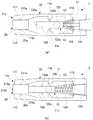
ついで、図7(a)に示すように、引出体123を摘んで後方に引くと、押圧体122がコイルばね124の付勢力に抗して後方へ移動し、押圧体122の係合突部122b,122cが保持部11b,11cを乗り越えて係止される。この後、穿刺ボタン125を下方に押圧すると、解除片125aが保持部11b,11cを押圧して係合突部122b,122cの係止状態が解除され、押圧体122は、コイルばね124の付勢力によって前方に発射される。これにより、押圧体122の駆動突部122aは、図2に示す穿刺針カートリッジ20の針本体21の後端に衝突する結果、図7(b)に示すように、針本体21は、穿刺部212aの先端212cがケーシング22の前方に突出し、穿刺を行うことができる。 Next, as shown in FIG. 7A, when the pulling
図8は、穿刺時における穿刺針カートリッジ20の内部を示す断面図である。針本体21は、両側から可撓片225a,225bによって挟持されると共に、ガイド突起213(図3参照)がガイド溝222に係合することにより、穿刺部212aの軸線方向に沿って正確に移動する。したがって、針本体21に対する駆動突部122aの衝突位置や衝突方向による穿刺方向のばらつきを防止することができ、穿刺作業を簡便且つ確実に行うことができる。また、このように、プランジャ12の駆動突部122aと針本体21とが分離されていることにより、穿刺後のコイルばね124の振動による2度突きも防止することができる。 FIG. 8 is a cross-sectional view showing the inside of the
台座部211に形成された係合部211a,211bは、前方から後方に向けて台座部211の幅が拡がるように形成されているので、針本体21の前方への移動により、係合部211a,211bと摺接する可撓片225a,225bのたわみ量が徐々に大きくなる結果、このたわみを元に戻そうとする弾性力も徐々に大きくなる。図8は、穿刺部212aの先端212cが、ケーシング22から外方に突出した最先位置にある状態(すなわち、針本体21が突出位置にある状態)を示しており、この状態から針本体21は、可撓片225a,225bに蓄積された弾性力の解放により後方への付勢力が作用し、図2に示す退避位置まで後退する。本実施形態のように係合部211a,211bの先端に段部211c,211dが形成されている場合には、針本体21の後方への移動により段部211c,211dが可撓片225a,225bの前面に接触して後方への付勢力が吸収されるため、針本体21を退避位置に確実に保持することができる。 Since the engaging
穿刺の終了後は、穿刺器具本体10の装着部11aから穿刺針カートリッジ20を取り外し、新たな穿刺針カートリッジ20を装着して、再び穿刺を行うことができる。 After the puncture is completed, the
本実施形態の穿刺器具1によれば、上記のように、穿刺針カートリッジ20の針本体21が、可撓片225a,225bによって、穿刺前は退避位置に保持される一方、穿刺後は突出位置から退避位置に付勢されるため、穿刺の前後において、穿刺部212aをケーシング22内に確実に保持することができる。したがって、穿刺部212aをキャップ等で覆う必要がなく、簡素な構成により作業性の向上や低コスト化を図ることができると共に、穿刺部212aが被験者に視認されにくくなり、被験者の恐怖感や不安感を抑制することができる。 According to the
針本体21における係合部211a,211bの傾斜角度は、針本体21に作用する押圧力が一定であれば、穿刺部212aの突出長さと相関を有しており、傾斜角度が大きいほど突出長さは小さく、傾斜角度が小さいほど突出長さは大きくなる。したがって、この傾斜角度を適宜設定することにより、穿刺部212aの突出長さを制御することができる。具体的には、図2に示すように、係合部211aの傾斜角度をθとしたときに、tanθが1/2から1/3の範囲にあることが好ましい。 The inclination angles of the engaging
また、本実施形態の係合部211a,211bを構成する傾斜面は、本実施形態のように必ずしも平面状(すなわち、平面視が直線状)である必要はなく、先細となるように傾斜する限り、平面視が円弧状、楕円弧状などの湾曲面であってもよく、或いは、平面と湾曲面との組み合わせから構成されていてもよい。更に、平面視が階段状となるように傾斜面を形成することも可能である。 Further, the inclined surfaces constituting the engaging
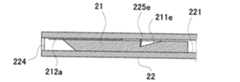
また、本発明において、ガイド溝222及びガイド突起213は必ずしも必須のものではなく、針本体21を両側から挟持する可撓片225a,225bによって、針本体21の前後方向の移動を案内することも可能である。また、可撓片225a,225bは、本実施形態では針本体21の両側にそれぞれ設けているが、針本体21の片側のみに可撓片を設け、反対側はケーシング22の内壁面と摺動させることによって、針本体21を所定の方向に案内することもできる。例えば、図9に断面図で示すように、針本体21の上面の一部に、傾斜面からなる係合部211eを窪み状に形成し、ケーシング22の上蓋内面から下方に突出する可撓片225eを係合部211eに係合させると共に、針本体21の下面はケーシング22の底面221と摺動させることにより、針本体21の左右方向のぶれを規制して、前後方向に移動を案内することができる。 In the present invention, the
但し、可撓片と係合する係合部の傾斜面は、本発明の効果を奏する上で必須のものではない。例えば、図10に示すように、台座部211の左右両側に形成したスリット状の切欠溝を係合部211f,211gとして、これらの係合部211f,211gに可撓片225f,225gの先端部を収容した構成にすることも可能であり、突出位置にある針本体21を退避位置に付勢する付勢手段として可撓片225f,225gを機能させることができる。 However, the inclined surface of the engaging portion that engages with the flexible piece is not indispensable for achieving the effects of the present invention. For example, as shown in FIG. 10, slit-shaped notch grooves formed on the left and right sides of the
また、本実施形態において、係合部211a,211bの先端に形成された段部211c,211dは、退避位置への針本体21の復帰及び保持を確実にすることを可能にしているが、この段部211c,211dの形状は、本実施形態のように、穿刺部212aの軸線に対して必ずしも垂直な面である必要はなく、例えば、図11に示すように、前方外側に向けて拡がるような傾斜面を段部211h,211iとすることもできる。 In the present embodiment, the
更に、図11の構成においては、針本体21とケーシング22とを一体成形する場合に、成形後における針本体21とケーシング22との連結箇所が可撓片225a,225bの先端のみであることから、両者を容易に分離することができ、製造コストの低減を図ることができる。 Further, in the configuration of FIG. 11, when the
針本体21及びケーシング22を一体成形する場合、両者は必ずしも分離する必要はなく、可撓片を介して両者が連結されたまま使用することもできる。例えば、図12に示すように、可撓片225j,211kを湾曲させて伸縮可能に形成し、この可撓片225j,211kを介して針本体21およびケーシング22が一体化された構成であってもよい。可撓片225j,211kの配置は、図12に示すように針本体21の側方とすることができるが、針本体21の後方とすることにより、突出位置から退避位置に向けた付勢力がより大きく作用するように構成することも可能である。 When the
また、可撓片と係合する係合部は、本実施形態においては台座部211の中央付近に切欠状に形成しているが、その位置は特に限定されるものではなく、例えば、支持部212に向けて先細になるように台座部211の先端付近に形成された傾斜部を、係合部とすることもできる。 Further, in the present embodiment, the engaging portion that engages with the flexible piece is formed in a notch shape near the center of the
また、本実施形態においては、穿刺部212aの軸線に垂直な面に沿って可撓片を形成しているが、図13(a)に示すように、穿刺部212aの軸線と同じ方向に延びるように可撓片225l,225mを形成し、針本体21の側面から外方に張り出すように形成された先細の係合部211l,211mに可撓片225l,225mの先端を係合させることも可能である。この構成においては、針本体21が突出位置まで前進すると、図13(b)に示すように、可撓片225l,225mが外方に撓んで針本体21を挟持した状態になり、退避位置に向けた付勢力を作用させることができる。この場合、図14に示すように、可撓片225n,225oを湾曲した形状にすることで、穿刺部212aの突出長さや付勢力を調整することができる。 In the present embodiment, the flexible piece is formed along a plane perpendicular to the axis of the
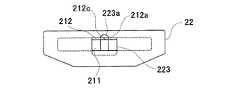
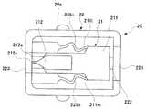
また、図15に示すように、可撓片225p,225qの突出方向先端に、平面視円弧状の当接部2251p,2251qを設け、この当接部2251p,2251qが平面視直線状の係合部211a,211bに当接するように構成してもよい。この構成によれば、針本体21が移動する際に、針本体21と可撓片225p,225qとが平面視でほぼ点接触となるため、両者の接触面積を低く抑えることができ、針本体21をスムーズに進退させることができる。当接部2251p,2251qの形状は、本実施形態においては円板状としているが、針本体21と接触する部分が平面視円弧状であればよく、例えば、半円板状、球状、半球状などとすることができる。 Further, as shown in FIG. 15,
また、図15に示すように、可撓片225p,225qは、ケーシング22の内壁面に固定された一端側と、当接部2251p,2251qが設けられた他端側との中心同士を結ぶ直線(図15に破線で示す)に対して、いずれも後方に凸となるように湾曲して形成されている。この構成によれば、突出位置にある針本体21に対して、退避位置に向けた十分な大きさの付勢力を容易に作用させることができ、針本体21を退避位置に確実に戻すことができる。 As shown in FIG. 15, the
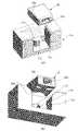
また、図15に示す穿刺針カートリッジ20は、ケーシング22の両側が先細となるように若干のテーパ形状を有すると共に、ケーシング22の後端面には半円状の窪み226が形成されている。この穿刺針カートリッジ20は、図16(a)及び(b)に斜視図で示すように、針本体が突出する開口223を前方に向けた状態で、穿刺器具本体の装着部11aに設けられた半円筒状のガイド体114の側壁に沿って窪み226の内壁面が摺動するように、穿刺針カートリッジ20を装着部11aに上方から装着することが可能である。穿刺針カートリッジ20のリブ20aが、装着部11aの係合凹部11bに係合することで、図17に示すように、装着部11aへの穿刺針カートリッジ20の装着が完了する。ガイド体114の中央には貫通孔115が形成されており、この貫通孔115を介して棒状の押圧体(図示せず)を真っ直ぐ進出させることができるので、穿刺針カートリッジ20の針本体の先端を開口223から確実に突出させることができる。 Further, the
穿刺針カートリッジの針本体に対して突出位置から退避位置に向けた付勢力を作用させる付勢手段としては、構成の簡素化と作動の確実性の観点から、上記の各種可撓片のように板ばね状のものが好ましいが、コイルばね、空気ばね、スポンジ、ゴムなどの種々の弾性体を使用することも可能である。これらの弾性体は、針本体21の両側にそれぞれ配置することで、穿刺部212aの軸線に沿って針本体21を進退させることが容易になり、簡便且つ確実な穿刺作業を可能にする。付勢手段としては、上記の他に、例えば、圧電素子等を利用したマイクロモータ等のマイクロアクチュエータを駆動して、ガイドワイヤーやギアー等を介して針本体21を付勢する構成であってもよい。 As the biasing means for applying a biasing force from the protruding position to the retracted position on the needle body of the puncture needle cartridge, from the viewpoint of simplification of the configuration and the certainty of operation, the above-mentioned various flexible pieces are used. A leaf spring is preferable, but various elastic bodies such as a coil spring, an air spring, a sponge, and rubber can also be used. By disposing these elastic bodies on both sides of the
上記の各実施形態に係る穿刺針カートリッジ20は、血液採取用として好適に用いることができるが、用途は特に限定されるものではなく、例えば、針本体21を介して生体組織の採取や薬剤の投与などを行うことも可能である。 The
また、上記の各実施形態においては、穿刺針カートリッジ20を、穿刺器具本体10に対して着脱可能な構成としているが、図2に示す穿刺針カートリッジ20において、例えば、針本体21の後端側に押圧部を設け、この押圧部を前方に向けて押圧することにより、穿刺器具本体を要することなく単独で穿刺が可能な穿刺装置とすることができる。 Further, in each of the embodiments described above, the
図18は、本発明の一実施形態に係る穿刺装置の断面図である。図18に示す穿刺装置30は、図2に示す穿刺針カートリッジ20と基本構成を同じくするものであり、図2と同様の構成部分には同一の符号を付して、詳細な説明を省略する。 FIG. 18 is a cross-sectional view of a puncture device according to an embodiment of the present invention. The
穿刺装置30は、ケーシング22の後端側にキャップ31を外嵌して構成されている。キャップ31の頂部(後部)内面には、蛇腹状のばね材32を介して連結されたプランジャ33と、ばね材32の両側に配置された解除突起34,35とが設けられている。ばね材32は、後部開口224を介してケーシング22内に延びている。プランジャ33は、先端が針本体21の後面に当接するように、ケーシング22の内部に配置されている。 The
また、ケーシング22内においてプランジャ33の両側には、一対のプランジャ受け36,37が設けられている。プランジャ受け36,37は、可撓性部材からなり、基部側がケーシング22の後部内面に固定され、先端側がプランジャ33の鍔部と係合して、プランジャ33の前方への移動を係止する。 A pair of
このような構成を有する穿刺装置30は、ケーシング22の先端を皮膚Sに押し付けた状態でキャップ31を矢示方向に押圧することにより、キャップ31が前方へ移動し、キャップ31とプランジャ33との間に介在するばね材32が縮んで、付勢力が蓄積される。そして、キャップ31を更に押圧すると、解除突起34,35の先端がプランジャ受け36,37と接触してこれを押し拡げることにより、プランジャ33の係止状態が解除される。この結果、ばね材32の付勢力によりプランジャ33が前方へ勢いよく移動し、針本体21と衝突することにより、皮膚Sに対する穿刺が行われる。穿刺後は、図2に示す穿刺針カートリッジ20と同様に、可撓片225a,225bの付勢力によって、針本体21が突出位置から退避位置に後退する。 In the
本実施形態の穿刺装置は、ケーシング22の後部開口224を介して針本体21を押圧可能に構成されており、針本体21による穿刺方向及び穿刺深さを正確に制御することができることから、セーフティランセットとして好適に使用することができ、更には、生体組織の採取やワクチンの摂取などを目的とする種々の医療用デバイスとして使用することができる。 The puncture device according to the present embodiment is configured to be able to press the
1 穿刺器具
10 穿刺器具本体
12 プランジャ
20 穿刺針カートリッジ
21 針本体
211a,211b 係合部
211c,211d 段部
212a 穿刺部
212c 先端
22 ケーシング
223,224 開口
225a,225b 可撓片DESCRIPTION OF
Claims (9)
Translated fromJapanese穿刺部を有する針本体と、
前記針本体を収容し、前記針本体の前方および後方にそれぞれ開口を有するケーシングとを備え、
前記針本体は、前記穿刺部の先端が前記ケーシング内に退避した退避位置と、前記穿刺器具本体から押圧力を受けて前記穿刺部の先端が前記ケーシングから外方に突出する突出位置との間で、進退可能に配置されており、
前記突出位置にある前記針本体を前記退避位置に付勢する付勢手段を備える穿刺針カートリッジにおいて、
前記付勢手段は、前記針本体の両側にそれぞれ配置された一対の可撓片を備え、
前記各可撓片は、一端側が前記ケーシング内に固定され、他端側が前記針本体と係合するように配置されており、
前記針本体は、先細となるように形成された傾斜面からなる一対の係合部を備え、
前記退避位置から前記突出位置に向けた前記針本体の移動により、前記各可撓片は、他端側が前記各係合部とそれぞれ摺接して、前記針本体の移動方向に沿ってたわみ変形することを特徴とする穿刺針カートリッジ。A puncture needle cartridge that is detachably attached to the puncture device body and constitutes the puncture device,
A needle body having a puncture portion;
A casing that houses the needle body, and has openings on the front and rear of the needle body, respectively.
The needle body is between a retracted position where the tip of the puncture part is retracted into the casing and a protruding position where the tip of the puncture part protrudes outward from the casing upon receiving a pressing force from the puncture device body. It is arranged so that it can move forward and backward,
In thepuncture needle cartridge comprising urging means for urging the needle body at the protruding position to the retracted position,
The biasing means includes a pair of flexible pieces disposed on both sides of the needle body,
Each of the flexible pieces is arranged such that one end side is fixed in the casing and the other end side is engaged with the needle body,
The needle body includes a pair of engaging portions formed of inclined surfaces formed to be tapered,
Due to the movement of the needle main body from the retracted position toward the protruding position, each flexible piece is slidably contacted with the respective engaging portion at the other end side and is deformed by bending along the moving direction of the needle main body. A puncture needle cartridge characterized by the above.
前記針本体を収容し、前記針本体の前方および後方にそれぞれ開口を有するケーシングとを備え、
前記針本体は、前記ケーシングの後部開口を介して押圧可能に構成され、前記穿刺部の先端が前記ケーシング内に退避した退避位置と、押圧により前記穿刺部の先端が前記ケーシングから外方に突出する突出位置との間で、進退可能に配置されており、
前記突出位置にある前記針本体を前記退避位置に付勢する付勢手段を備える穿刺装置において、
前記付勢手段は、前記針本体の両側にそれぞれ配置された一対の可撓片を備え、
前記各可撓片は、一端側が前記ケーシング内に固定され、他端側が前記針本体と係合するように配置されており、
前記針本体は、先細となるように形成された傾斜面からなる一対の係合部を備え、
前記退避位置から前記突出位置に向けた前記針本体の移動により、前記各可撓片は、他端側が前記各係合部とそれぞれ摺接して、前記針本体の移動方向に沿ってたわみ変形することを特徴とする穿刺装置。A needle body having a puncture portion;
A casing that houses the needle body, and has openings on the front and rear of the needle body, respectively.
The needle body is configured to be able to be pressed through a rear opening of the casing, and a retracted position in which the tip of the puncture portion is retracted into the casing, and the tip of the puncture portion protrudes outward from the casing by the press. It is arranged to be able to advance and retreat between the protruding position to
In thepuncture device comprising urging means for urging the needle body at the protruding position to the retracted position,
The biasing means includes a pair of flexible pieces disposed on both sides of the needle body,
Each of the flexible pieces is arranged such that one end side is fixed in the casing and the other end side is engaged with the needle body,
The needle body includes a pair of engaging portions formed of inclined surfaces formed to be tapered,
Due to the movement of the needle main body from the retracted position toward the protruding position, each flexible piece is slidably contacted with the respective engaging portion at the other end side and is deformed by bending along the moving direction of the needle main body. A puncture device characterized by that.
穿刺部を有する針本体と、 A needle body having a puncture portion;
前記針本体を収容し、前記針本体の前方および後方にそれぞれ開口を有するケーシングとを備え、 A casing that houses the needle body, and has openings on the front and rear of the needle body, respectively.
前記針本体は、前記穿刺部の先端が前記ケーシング内に退避した退避位置と、前記穿刺器具本体から押圧力を受けて前記穿刺部の先端が前記ケーシングから外方に突出する突出位置との間で、進退可能に配置されており、 The needle body is between a retracted position where the tip of the puncture part is retracted into the casing and a protruding position where the tip of the puncture part protrudes outward from the casing upon receiving a pressing force from the puncture device body. It is arranged so that it can move forward and backward,
前記突出位置にある前記針本体を前記退避位置に付勢する付勢手段を備える穿刺針カートリッジにおいて、 In the puncture needle cartridge comprising urging means for urging the needle body at the protruding position to the retracted position,
前記付勢手段は、前記針本体の両側にそれぞれ配置された一対の可撓片を備え、The biasing means includes a pair of flexible pieces disposed on both sides of the needle body,
前記各可撓片は、一端側が前記ケーシング内に固定され、他端側が前記針本体と係合するように配置されており、Each of the flexible pieces is arranged such that one end side is fixed in the casing and the other end side is engaged with the needle body,
前記針本体は、先細となるように形成された傾斜面からなる一対の係合部を備え、 The needle body includes a pair of engaging portions formed of inclined surfaces formed to be tapered,
一対の前記可撓片の先端に設けられた平面視円弧状の当接部が、平面視直線状の前記係合部にそれぞれ当接することを特徴とする穿刺針カートリッジ。A puncture needle cartridge, wherein a planar arcuate contact portion provided at the distal ends of the pair of flexible pieces abuts on the planarly engaging portion.
前記針本体を収容し、前記針本体の前方および後方にそれぞれ開口を有するケーシングとを備え、 A casing that houses the needle body, and has openings on the front and rear of the needle body, respectively.
前記針本体は、前記ケーシングの後部開口を介して押圧可能に構成され、前記穿刺部の先端が前記ケーシング内に退避した退避位置と、押圧により前記穿刺部の先端が前記ケーシングから外方に突出する突出位置との間で、進退可能に配置されており、 The needle body is configured to be able to be pressed through a rear opening of the casing, and a retracted position in which the tip of the puncture portion is retracted into the casing, and the tip of the puncture portion protrudes outward from the casing by the press. It is arranged to be able to advance and retreat between the protruding position to
前記突出位置にある前記針本体を前記退避位置に付勢する付勢手段を備える穿刺装置において、 In the puncture device comprising urging means for urging the needle body at the protruding position to the retracted position,
前記付勢手段は、前記針本体の両側にそれぞれ配置された一対の可撓片を備え、 The biasing means includes a pair of flexible pieces disposed on both sides of the needle body,
前記各可撓片は、一端側が前記ケーシング内に固定され、他端側が前記針本体と係合するように配置されており、 Each of the flexible pieces is arranged such that one end side is fixed in the casing and the other end side is engaged with the needle body,
前記針本体は、先細となるように形成された傾斜面からなる一対の係合部を備え、 The needle body includes a pair of engaging portions formed of inclined surfaces formed to be tapered,
一対の前記可撓片の先端に設けられた平面視円弧状の当接部が、平面視直線状の前記係合部にそれぞれ当接することを特徴とする穿刺装置。 2. A puncture device according to claim 1, wherein a planar arcuate contact portion provided at the distal ends of the pair of flexible pieces abuts on the engagement portion linearly viewed from above.
Priority Applications (1)
| Application Number | Priority Date | Filing Date | Title |
|---|---|---|---|
| JP2010515922AJP5386673B2 (en) | 2008-06-05 | 2009-06-04 | Puncture needle cartridge and puncture device |
Applications Claiming Priority (4)
| Application Number | Priority Date | Filing Date | Title |
|---|---|---|---|
| JP2008147629 | 2008-06-05 | ||
| JP2008147629 | 2008-06-05 | ||
| JP2010515922AJP5386673B2 (en) | 2008-06-05 | 2009-06-04 | Puncture needle cartridge and puncture device |
| PCT/JP2009/060284WO2009148133A1 (en) | 2008-06-05 | 2009-06-04 | Puncture needle cartridge and puncture device |
Publications (2)
| Publication Number | Publication Date |
|---|---|
| JPWO2009148133A1 JPWO2009148133A1 (en) | 2011-11-04 |
| JP5386673B2true JP5386673B2 (en) | 2014-01-15 |
Family
ID=41398206
Family Applications (1)
| Application Number | Title | Priority Date | Filing Date |
|---|---|---|---|
| JP2010515922AActiveJP5386673B2 (en) | 2008-06-05 | 2009-06-04 | Puncture needle cartridge and puncture device |
Country Status (4)
| Country | Link |
|---|---|
| US (1) | US8679144B2 (en) |
| EP (1) | EP2298173B1 (en) |
| JP (1) | JP5386673B2 (en) |
| WO (1) | WO2009148133A1 (en) |
Families Citing this family (13)
| Publication number | Priority date | Publication date | Assignee | Title |
|---|---|---|---|---|
| US20100256524A1 (en) | 2009-03-02 | 2010-10-07 | Seventh Sense Biosystems, Inc. | Techniques and devices associated with blood sampling |
| JP5668192B2 (en) | 2010-03-10 | 2015-02-12 | 株式会社ライトニックス | Medical needle and puncture device |
| US20130158482A1 (en)* | 2010-07-26 | 2013-06-20 | Seventh Sense Biosystems, Inc. | Rapid delivery and/or receiving of fluids |
| WO2012021801A2 (en) | 2010-08-13 | 2012-02-16 | Seventh Sense Biosystems, Inc. | Systems and techniques for monitoring subjects |
| WO2012064802A1 (en) | 2010-11-09 | 2012-05-18 | Seventh Sense Biosystems, Inc. | Systems and interfaces for blood sampling |
| CN103874461B (en) | 2011-04-29 | 2017-05-10 | 第七感生物系统有限公司 | Devices for collecting and/or manipulating blood spots or other bodily fluids |
| WO2012149155A1 (en) | 2011-04-29 | 2012-11-01 | Seventh Sense Biosystems, Inc. | Systems and methods for collecting fluid from a subject |
| KR102013466B1 (en) | 2011-04-29 | 2019-08-22 | 세븐쓰 센스 바이오시스템즈, 인크. | Delivering and/or receiving fluids |
| US20130158468A1 (en) | 2011-12-19 | 2013-06-20 | Seventh Sense Biosystems, Inc. | Delivering and/or receiving material with respect to a subject surface |
| USD732162S1 (en)* | 2013-03-14 | 2015-06-16 | Eli Lilly And Company | Automatic injection device |
| CN104856699B (en)* | 2014-05-21 | 2018-02-13 | 广州市恒诚空调设备维修有限公司 | A kind of bullet unloads formula blood collecting pen structure |
| CN112155563A (en)* | 2015-01-20 | 2021-01-01 | 广州市健之堂医疗器械有限公司 | Safe blood taking needle structure |
| CN113712646A (en)* | 2021-09-27 | 2021-11-30 | 刘旺 | Clinical B-type ultramicro-wound operation puncture positioner |
Family Cites Families (23)
| Publication number | Priority date | Publication date | Assignee | Title |
|---|---|---|---|---|
| US4535769A (en)* | 1981-03-23 | 1985-08-20 | Becton, Dickinson And Company | Automatic retractable lancet assembly |
| US4990154A (en) | 1989-06-19 | 1991-02-05 | Miles Inc. | Lancet assembly |
| SE468620B (en)* | 1991-05-07 | 1993-02-22 | Hans Enstroem | DEPOSITION OF SINGLE TYPE FOR PRESENTING SKIN |
| JPH0638910U (en)* | 1992-10-27 | 1994-05-24 | 株式会社メイテック | Blood collection needle |
| AUPQ089299A0 (en)* | 1999-06-10 | 1999-07-01 | N & V Curie Pty Ltd | Disposable lancet device |
| KR100788305B1 (en)* | 2001-01-12 | 2007-12-27 | 아크레이 인코퍼레이티드 | Puncture device, its manufacture method, pump mechanism and suction device |
| EP1396226B1 (en)* | 2001-06-11 | 2013-08-21 | ARKRAY, Inc. | Measuring apparatus comprising a puncturing element integration mounting body |
| DE10345663A1 (en)* | 2003-06-27 | 2005-01-20 | Senslab-Gesellschaft Zur Entwicklung Und Herstellung Bioelektrochemischer Sensoren Mbh | Diagnostic or analytical disposable with integrated lancet |
| PL207804B1 (en)* | 2003-07-29 | 2011-02-28 | Htl Strefa Społka Z Ograniczoną Odpowiedzialnością | Piercing apparatus |
| US9380975B2 (en) | 2004-05-07 | 2016-07-05 | Becton, Dickinson And Company | Contact activated lancet device |
| KR101121072B1 (en)* | 2004-05-07 | 2012-03-15 | 벡톤 디킨슨 앤드 컴퍼니 | Contact activated lancet device |
| ES2746309T3 (en) | 2004-05-07 | 2020-03-05 | Becton Dickinson Co | Cam Powered Medical Puncture Device |
| WO2006004664A1 (en)* | 2004-06-25 | 2006-01-12 | Facet Technologies, Llc | Low cost safety lancet |
| DE102005003789A1 (en)* | 2005-01-19 | 2006-07-27 | Roche Diagnostics Gmbh | Test unit for one-time examinations of a body fluid |
| PL2425776T3 (en) | 2005-04-07 | 2013-12-31 | Becton Dickinson Co | Lancet device |
| JP4536590B2 (en) | 2005-05-16 | 2010-09-01 | パナソニック株式会社 | Puncture tool |
| KR100904106B1 (en) | 2005-04-28 | 2009-06-24 | 파나소닉 주식회사 | Needle insertion instrument and insertion needle cartridge |
| EP1716808A1 (en)* | 2005-04-29 | 2006-11-02 | Eumed Biotechnology Co., Ltd. | Safety lancet device |
| US8469984B2 (en)* | 2005-10-25 | 2013-06-25 | Bayer Healthcare Llc | Single use lancing device |
| US20070162065A1 (en)* | 2006-01-12 | 2007-07-12 | Mu-Shen Chen | Disposable lancet device |
| JPWO2007088875A1 (en)* | 2006-02-01 | 2009-06-25 | アークレイ株式会社 | Lancet |
| US20090093832A1 (en) | 2006-03-10 | 2009-04-09 | Arkray, Inc. | Lancet device |
| PL216241B1 (en)* | 2007-01-10 | 2014-03-31 | Htl Strefa Społka Akcyjna | Device for puncture of patient's skin |
- 2009
- 2009-06-04JPJP2010515922Apatent/JP5386673B2/enactiveActive
- 2009-06-04EPEP09758400Apatent/EP2298173B1/ennot_activeNot-in-force
- 2009-06-04USUS12/737,041patent/US8679144B2/enactiveActive
- 2009-06-04WOPCT/JP2009/060284patent/WO2009148133A1/enactiveApplication Filing
Also Published As
| Publication number | Publication date |
|---|---|
| US8679144B2 (en) | 2014-03-25 |
| WO2009148133A1 (en) | 2009-12-10 |
| EP2298173A1 (en) | 2011-03-23 |
| EP2298173A4 (en) | 2011-09-07 |
| US20120089050A1 (en) | 2012-04-12 |
| JPWO2009148133A1 (en) | 2011-11-04 |
| EP2298173B1 (en) | 2012-10-24 |
Similar Documents
| Publication | Publication Date | Title |
|---|---|---|
| JP5386673B2 (en) | Puncture needle cartridge and puncture device | |
| JP5313923B2 (en) | Patient skin puncture device | |
| JP4573878B2 (en) | Puncture system for collecting body fluid | |
| TWI574669B (en) | Lancet device with lance retraction | |
| US5269800A (en) | Blood lancing device | |
| JP5668192B2 (en) | Medical needle and puncture device | |
| KR101205396B1 (en) | Squeeze-activated medical puncturing device | |
| EP2030579A3 (en) | Surgical instrument having a plastic surface | |
| CN101304697A (en) | Method and device for inserting a sensor | |
| JP2002143132A (en) | Lancet system | |
| KR101716529B1 (en) | Disposable blood collecting instrument | |
| JP2018191702A (en) | Applicator, tape cartridge unit, and array cartridge unit | |
| JP5291337B2 (en) | Cam-operated medical puncture device and method | |
| CN101677787A (en) | Pricking device for taking blood, comprising a leg spring | |
| JP5587721B2 (en) | Puncture device | |
| JP4491280B2 (en) | Puncture needle and puncture device | |
| JPWO2012133267A1 (en) | Puncture device | |
| CN111757989A (en) | Relieving pain at a medical treatment site | |
| JP5190066B2 (en) | Puncture device | |
| JP4544002B2 (en) | Lancet with needle protector | |
| JP2014200473A (en) | Puncture device and puncture system | |
| JP2009056163A (en) | Puncturing device | |
| JP2009039146A (en) | Puncture device and biosensor device | |
| JP2020162776A (en) | Mounting device | |
| JP6200754B2 (en) | Puncture tool |
Legal Events
| Date | Code | Title | Description |
|---|---|---|---|
| RD02 | Notification of acceptance of power of attorney | Free format text:JAPANESE INTERMEDIATE CODE: A7422 Effective date:20110728 | |
| RD04 | Notification of resignation of power of attorney | Free format text:JAPANESE INTERMEDIATE CODE: A7424 Effective date:20110728 | |
| A621 | Written request for application examination | Free format text:JAPANESE INTERMEDIATE CODE: A621 Effective date:20120417 | |
| A131 | Notification of reasons for refusal | Free format text:JAPANESE INTERMEDIATE CODE: A131 Effective date:20130329 | |
| A521 | Request for written amendment filed | Free format text:JAPANESE INTERMEDIATE CODE: A523 Effective date:20130523 | |
| TRDD | Decision of grant or rejection written | ||
| A01 | Written decision to grant a patent or to grant a registration (utility model) | Free format text:JAPANESE INTERMEDIATE CODE: A01 Effective date:20130726 | |
| A61 | First payment of annual fees (during grant procedure) | Free format text:JAPANESE INTERMEDIATE CODE: A61 Effective date:20130807 | |
| R150 | Certificate of patent or registration of utility model | Ref document number:5386673 Country of ref document:JP Free format text:JAPANESE INTERMEDIATE CODE: R150 Free format text:JAPANESE INTERMEDIATE CODE: R150 | |
| R250 | Receipt of annual fees | Free format text:JAPANESE INTERMEDIATE CODE: R250 | |
| R250 | Receipt of annual fees | Free format text:JAPANESE INTERMEDIATE CODE: R250 | |
| R250 | Receipt of annual fees | Free format text:JAPANESE INTERMEDIATE CODE: R250 | |
| R250 | Receipt of annual fees | Free format text:JAPANESE INTERMEDIATE CODE: R250 | |
| R250 | Receipt of annual fees | Free format text:JAPANESE INTERMEDIATE CODE: R250 | |
| R250 | Receipt of annual fees | Free format text:JAPANESE INTERMEDIATE CODE: R250 |