JP5386504B2 - Medical catheter with flexible pull ring and distal tip attachment device - Google Patents
Medical catheter with flexible pull ring and distal tip attachment deviceDownload PDFInfo
- Publication number
- JP5386504B2 JP5386504B2JP2010539565AJP2010539565AJP5386504B2JP 5386504 B2JP5386504 B2JP 5386504B2JP 2010539565 AJP2010539565 AJP 2010539565AJP 2010539565 AJP2010539565 AJP 2010539565AJP 5386504 B2JP5386504 B2JP 5386504B2
- Authority
- JP
- Japan
- Prior art keywords
- shaft
- catheter
- assembly according
- pull ring
- catheter assembly
- Prior art date
- Legal status (The legal status is an assumption and is not a legal conclusion. Google has not performed a legal analysis and makes no representation as to the accuracy of the status listed.)
- Expired - Fee Related
Links
- 239000012530fluidSubstances0.000claimsdescription30
- 238000002679ablationMethods0.000claimsdescription29
- 230000006835compressionEffects0.000claimsdescription27
- 238000007906compressionMethods0.000claimsdescription27
- 230000001070adhesive effectEffects0.000claimsdescription8
- 239000000853adhesiveSubstances0.000claimsdescription7
- 230000002262irrigationEffects0.000description5
- 238000003973irrigationMethods0.000description5
- BASFCYQUMIYNBI-UHFFFAOYSA-NplatinumChemical compound[Pt]BASFCYQUMIYNBI-UHFFFAOYSA-N0.000description2
- 238000005452bendingMethods0.000description1
- 230000000747cardiac effectEffects0.000description1
- 238000003745diagnosisMethods0.000description1
- 230000004064dysfunctionEffects0.000description1
- 230000000694effectsEffects0.000description1
- 239000000463materialSubstances0.000description1
- 230000004048modificationEffects0.000description1
- 238000012986modificationMethods0.000description1
- 229910052697platinumInorganic materials0.000description1
- 230000002787reinforcementEffects0.000description1
Images


Classifications
- A—HUMAN NECESSITIES
- A61—MEDICAL OR VETERINARY SCIENCE; HYGIENE
- A61M—DEVICES FOR INTRODUCING MEDIA INTO, OR ONTO, THE BODY; DEVICES FOR TRANSDUCING BODY MEDIA OR FOR TAKING MEDIA FROM THE BODY; DEVICES FOR PRODUCING OR ENDING SLEEP OR STUPOR
- A61M25/00—Catheters; Hollow probes
- A61M25/01—Introducing, guiding, advancing, emplacing or holding catheters
- A61M25/0105—Steering means as part of the catheter or advancing means; Markers for positioning
- A61M25/0133—Tip steering devices
- A61M25/0147—Tip steering devices with movable mechanical means, e.g. pull wires
- A—HUMAN NECESSITIES
- A61—MEDICAL OR VETERINARY SCIENCE; HYGIENE
- A61B—DIAGNOSIS; SURGERY; IDENTIFICATION
- A61B18/00—Surgical instruments, devices or methods for transferring non-mechanical forms of energy to or from the body
- A61B18/04—Surgical instruments, devices or methods for transferring non-mechanical forms of energy to or from the body by heating
- A61B18/12—Surgical instruments, devices or methods for transferring non-mechanical forms of energy to or from the body by heating by passing a current through the tissue to be heated, e.g. high-frequency current
- A61B18/14—Probes or electrodes therefor
- A61B18/1492—Probes or electrodes therefor having a flexible, catheter-like structure, e.g. for heart ablation
- A—HUMAN NECESSITIES
- A61—MEDICAL OR VETERINARY SCIENCE; HYGIENE
- A61B—DIAGNOSIS; SURGERY; IDENTIFICATION
- A61B17/00—Surgical instruments, devices or methods
- A61B17/00234—Surgical instruments, devices or methods for minimally invasive surgery
- A61B2017/00292—Surgical instruments, devices or methods for minimally invasive surgery mounted on or guided by flexible, e.g. catheter-like, means
- A61B2017/003—Steerable
- A—HUMAN NECESSITIES
- A61—MEDICAL OR VETERINARY SCIENCE; HYGIENE
- A61B—DIAGNOSIS; SURGERY; IDENTIFICATION
- A61B18/00—Surgical instruments, devices or methods for transferring non-mechanical forms of energy to or from the body
- A61B18/04—Surgical instruments, devices or methods for transferring non-mechanical forms of energy to or from the body by heating
- A61B18/12—Surgical instruments, devices or methods for transferring non-mechanical forms of energy to or from the body by heating by passing a current through the tissue to be heated, e.g. high-frequency current
- A61B18/14—Probes or electrodes therefor
- A61B2018/1472—Probes or electrodes therefor for use with liquid electrolyte, e.g. virtual electrodes
- A—HUMAN NECESSITIES
- A61—MEDICAL OR VETERINARY SCIENCE; HYGIENE
- A61M—DEVICES FOR INTRODUCING MEDIA INTO, OR ONTO, THE BODY; DEVICES FOR TRANSDUCING BODY MEDIA OR FOR TAKING MEDIA FROM THE BODY; DEVICES FOR PRODUCING OR ENDING SLEEP OR STUPOR
- A61M25/00—Catheters; Hollow probes
- A61M25/01—Introducing, guiding, advancing, emplacing or holding catheters
- A61M25/0105—Steering means as part of the catheter or advancing means; Markers for positioning
- A61M25/0133—Tip steering devices
- A61M25/0147—Tip steering devices with movable mechanical means, e.g. pull wires
- A61M2025/015—Details of the distal fixation of the movable mechanical means
Landscapes
- Health & Medical Sciences (AREA)
- Engineering & Computer Science (AREA)
- Life Sciences & Earth Sciences (AREA)
- Heart & Thoracic Surgery (AREA)
- Veterinary Medicine (AREA)
- Public Health (AREA)
- General Health & Medical Sciences (AREA)
- Animal Behavior & Ethology (AREA)
- Surgery (AREA)
- Biomedical Technology (AREA)
- Molecular Biology (AREA)
- Mechanical Engineering (AREA)
- Otolaryngology (AREA)
- Nuclear Medicine, Radiotherapy & Molecular Imaging (AREA)
- Plasma & Fusion (AREA)
- Physics & Mathematics (AREA)
- Cardiology (AREA)
- Medical Informatics (AREA)
- Biophysics (AREA)
- Pulmonology (AREA)
- Anesthesiology (AREA)
- Hematology (AREA)
- Surgical Instruments (AREA)
- Media Introduction/Drainage Providing Device (AREA)
Description
Translated fromJapanese(関連出願の相互参照)
本発明は、2007年12月21日に出願された米国特許出願第11/963,393号(393号出願)の優先権を主張する。393号出願は、その全文が本願に記載されるものとして、参照によりここに組み込まれる。
本発明は、医療用カテーテルに関し、特に、カテーテルシャフトおよびそれに取り付けられた遠位先端を所望の方向に曲げるために、撓み可能なカテーテルシャフトの遠位端近傍に撓みプルリングを使用するアブレーションカテーテルに関する。(Cross-reference of related applications)
The present invention claims the priority of US patent application Ser. No. 11 / 963,393 (No. 393) filed on Dec. 21, 2007. The 393 application is hereby incorporated by reference as if fully set forth herein.
The present invention relates to medical catheters, and more particularly to an ablation catheter that uses a flexible pull ring near the distal end of the deflectable catheter shaft to bend the catheter shaft and the distal tip attached thereto in a desired direction.
様々な病状の診断および治療に使用される医療用カテーテルは、世界中で広く使用されている。それは一般に、撓み変形可能なカテーテルシャフトと、カテーテルシャフトの近位端を支持するハンドルアクチュエータと、カテーテルシャフトの遠位端近傍に配置された撓みプルリングとプルリングからハンドルアクチュエータへ延伸するプルワイヤとを含むプルリングアセンブリと、カテーテルシャフトの遠位端に接続された専用の先端部を備えた遠位先端と、を含む。ハンドルアクチュエータを操作することによってプルワイヤを引くことにより、撓みプルリングを傾斜させ、あるいは揺動させ、カテーテルシャフトを所望の態様で曲げることができる。 Medical catheters used for the diagnosis and treatment of various medical conditions are widely used throughout the world. It generally includes a flexible deformable catheter shaft, a handle actuator that supports the proximal end of the catheter shaft, a flexible pull ring disposed near the distal end of the catheter shaft, and a pull wire that extends from the pull ring to the handle actuator. An assembly and a distal tip with a dedicated tip connected to the distal end of the catheter shaft. By pulling the pull wire by manipulating the handle actuator, the flexible pull ring can be tilted or swung to bend the catheter shaft in a desired manner.
アブレーションカテーテルは、例えば、心機能不全の治療等において、組織をアブレーションするために使用される、医療用カテーテルの1種である。それは、灌注式(アブレーションエネルギに加えて、アブレーション流体を排出する)または非灌注式(そこからアブレーション流体を排出しない)である。その遠位先端は、先端電極を含み、先端電極へエネルギを供給するために、エネルギ源がハンドルアクチュエータに接続される。灌注アブレーションカテーテルにおいて、流体マニホールドは、先端電極に取り付けられるか、あるいは、先端電極と一体化されている。アブレーション流体を供給するために、流体源がハンドルアクチュエータに取り付けられる。遠位先端は、隣接する撓み可能なカテーテルシャフトの遠位端と接続して協働する装着シャフトを含むことができる。 An ablation catheter is a type of medical catheter used to ablate tissue, for example, in the treatment of cardiac dysfunction. It is irrigated (which drains ablation fluid in addition to ablation energy) or non-irrigated (does not drain ablation fluid therefrom). The distal tip includes a tip electrode, and an energy source is connected to the handle actuator for supplying energy to the tip electrode. In irrigation ablation catheters, the fluid manifold is attached to or integrated with the tip electrode. A fluid source is attached to the handle actuator to supply ablation fluid. The distal tip can include a mounting shaft that cooperates with the distal end of an adjacent deflectable catheter shaft.
しかし、灌注式および非灌注式のアブレーションカテーテルを含む多くの医療用カテーテルにおいて、遠位先端は、接着剤を使用してカテーテルシャフトの遠位端に取り付けられる。時間の経過により、これらの接着剤はその接着特性を失い、遠位先端に緩みが生じる可能性があることがわかった。これは、避けなければならない危険な状況である。 However, in many medical catheters, including irrigated and non-irrigated ablation catheters, the distal tip is attached to the distal end of the catheter shaft using an adhesive. Over time, it has been found that these adhesives lose their adhesive properties and can loosen the distal tip. This is a dangerous situation that must be avoided.
また、ハンドルアクチュエータの操作によってプルリングの傾斜および揺動が繰り返されると、プルリングがカテーテルシャフトに沿ってハンドルアクチュエータの方向へ向けて、且つ、遠位端から離れて潜動する可能性があり、従って、結果として、カテーテルシャフトを所望の態様で撓ませる効果が減少する。 Also, if the pulling and tilting of the pull ring is repeated by manipulation of the handle actuator, the pull ring may dive along the catheter shaft in the direction of the handle actuator and away from the distal end, thus As a result, the effect of deflecting the catheter shaft in the desired manner is reduced.
本発明の目的は、遠位先端をカテーテルシャフトに確実に接続する、医療用カテーテルのカテーテルシャフトへ遠位先端を取り付けるための取付器具を提供することである。 It is an object of the present invention to provide an attachment device for attaching a distal tip to a catheter shaft of a medical catheter that securely connects the distal tip to the catheter shaft.
本発明の別の目的は、プルリングがカテーテルシャフトに沿って潜動するのを防止する、医療用カテーテルのカテーテルシャフトへ遠位先端を取り付けるための取付器具を提供することである。 Another object of the present invention is to provide an attachment device for attaching a distal tip to a catheter shaft of a medical catheter that prevents the pull ring from submerging along the catheter shaft.
本発明のさらなる目的は、灌注アブレーションカテーテルまたは非灌注アブレーションカテーテルのいずれにおいても前述の成果を達成する取付器具を提供することである。 It is a further object of the present invention to provide an attachment device that achieves the aforementioned results in either an irrigated ablation catheter or a non-irrigated ablation catheter.
前述の目的は、カテーテルシャフトおよび遠位先端を一緒に固定するために遠位先端の装着シャフトに対してカテーテルシャフトを圧迫する圧迫リングを含む取付器具によって、達成される。1つの実施形態において、圧迫リングは、装着シャフトの外側表面に対してカテーテルシャフトを内向きに圧縮する。別の実施形態において、圧迫リングは、装着シャフトの内側表面に対してカテーテルシャフトを外向きに押圧する。カテーテルシャフトの外側に且つプルリングとハンドルアクチュエータとの間に配置されるときに、圧迫リングは、使用中にプルリングがハンドルアクチュエータに向けて潜動するのを防止する当接を提供することができる。 The foregoing objects are achieved by an attachment device that includes a compression ring that compresses the catheter shaft against the distal tip mounting shaft to secure the catheter shaft and distal tip together. In one embodiment, the compression ring compresses the catheter shaft inward against the outer surface of the mounting shaft. In another embodiment, the compression ring presses the catheter shaft outward against the inner surface of the mounting shaft. When placed on the outside of the catheter shaft and between the pull ring and handle actuator, the compression ring can provide an abutment that prevents the pull ring from submerging toward the handle actuator during use.
取付器具は、装着シャフトが圧迫リングを超えて滑るのを防止するために、装着シャフト上に、例えば環状リップ等の、外向きに延出する特徴部を含むことができる。取付器具は、カテーテルシャフトの内部表面を把持するために、装着シャフトの外側表面に表面凹凸(例えば、鉤状部)等の特徴部を含むことができ、または、中に延伸する装着シャフトの外側表面を把持するために、装着シャフトの内部表面に表面凹凸(例えば、鉤状部)等の特徴部を含むことができる。さらに別の実施形態において、圧迫リングは、カテーテルシャフト内に挿入されるものであってもよい。これとは反対に、当該カテーテルシャフトは、遠位先端の装着シャフトによって、その外側表面を把持されていてもよい。 The mounting device can include an outwardly extending feature on the mounting shaft, such as an annular lip, to prevent the mounting shaft from sliding past the compression ring. The mounting device can include features such as surface irregularities (eg, ridges) on the outer surface of the mounting shaft to grip the inner surface of the catheter shaft, or the outer surface of the mounting shaft that extends into it. In order to grip the surface, the inner surface of the mounting shaft can include features such as surface irregularities (eg, ridges). In yet another embodiment, the compression ring may be inserted into the catheter shaft. Conversely, the catheter shaft may be gripped on its outer surface by a distal tip mounting shaft.
本発明のさらなる態様および利点は、下記の記載と併せて、添付の図面を参照することによって、より詳細にに理解される。 Further aspects and advantages of the present invention will be understood in more detail by reference to the accompanying drawings in conjunction with the following description.
図1は、本発明の実施形態に従った灌注アブレーションカテーテルシステム10を示す。これは、アブレーションカテーテル20と、取付器具40によってアブレーションカテーテルの遠位端部分に取り付けられた遠位先端30と、アブレーションカテーテル20の近位端を支持するハンドルアクチュエータ50と、を具備するアブレーションカテーテルアセンブリを含む。灌注アブレーションカテーテルシステム10の一部として、カテーテル20を経由して遠位先端30へエネルギおよび流体を供給するために、エネルギ源60および流体源70が、ハンドルアクチュエータ50に接続される。 FIG. 1 shows an irrigation
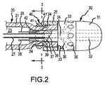
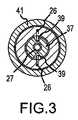
図2および図3は、カテーテル20の遠位端部分と、遠位先端30と、取付器具40と、を示す。カテーテル20は、遠位端22および中空内部23を画定する、湾曲可能且つ圧迫変形可能なカテーテルシャフト21を含む。ガイドチャネル24は、遠位端22近傍において互いに直径方向に対向する位置で、カテーテルシャフトの壁を通って延伸する。プルリングアセンブリは、遠位端22近傍でシャフト21のまわりに位置する撓みプルリング25と、ガイドチャネル24を通って中空内部23内に延伸しハンドルアクチュエータ50へ戻る、プルリング上に直径方向に互いに対向した位置で取り付けられたプルワイヤ26と、を含む。各プルワイヤ26は、プルリング25をカテーテルシャフトに対して傾斜させるか揺動させ、それによって、カテーテルシャフトの遠位端部分を第1の方向にまたは第2の反対方向に公知のやり方で曲げるために、ハンドルアクチュエータ50のトリガを手動で操作することによって、それぞれ牽引される。流体送出チューブ27は、ハンドルアクチュエータ50から中空内部23を通って遠位端22へ向けて延伸しており、このチューブには流体源70によって流体が供給される。 FIGS. 2 and 3 show the distal end portion of the
遠位先端30は、先端電極31と、流体マニホールド33と、装着シャフト37と、を含む。装着シャフト37は、流体マニホールド33と一体であり、カテーテルシャフトの中空内部23内に延伸する。装着シャフト37は、流体送出チューブ27がその中に気密的に延伸する中心軸方向通路38と、その外側表面上において直径方向に互いに対向して位置し、中にプルワイヤ26が延伸することができる軸方向チャネル39と、を含む。 The
流体マニホールド33は形状が円筒形であり、軸方向通路38の延長である中心軸方向通路34と、軸方向通路34から外周のまわりに間隔をおいて位置する開口部36へ延伸するチャネル35と、画定する。流体送出チューブ27から軸方向通路38へ供給された流体は、軸方向通路34へ流れ、次いで、チャネル35を通って、開口部36へ流れ、そこから排出される。別の実施形態において、流体マニホールドは、1つの開口部36へ導く1つのみのチャネル35を含んでもよい。 The
先端電極31は、軸方向通路34からその遠位端へ流体を送出するために複数のチャネル32(図2では、点線で示される)を含むことができる(別の実施形態においては、1つのチャネルのみが提供される)。先端電極31は、接着剤等の公知のやり方で流体マニホールドに接続され、プラチナ等のよく知られた材料で作ることができる。 The
取付器具40は、プルリングとハンドルアクチュエータ50との間であって、プルリング25に隣接したカテーテルシャフト21のまわりに配置される圧迫リング41を含む。圧迫リング41は、流体マニホールド33および先端電極31をカテーテルシャフトの遠位端部分に固定するために、装着シャフト37に対してカテーテルシャフト21を圧迫するような大きさとなっている。これはまた、プルワイヤ26によってプルリングが繰り返して傾斜することにより発生するハンドルアクチュエータ50に向かうプルリング25の移動に対する留め具をも提供する。圧迫リング41は、プルリング25に面する傾斜表面41’を有し、表面41’に対するプルリングの移動により、プルリングをして、装着シャフト37に対してカテーテルシャフト21をさらに圧迫させるようにする。 The
取付器具はまた、中空内部23内の装着シャフト37の自由端に環状リップ42の形態で外向きに突出する表面特徴部も含む。外向きに突出する環状リップ42は、装着シャフト37(および、全体として遠位先端も含む)がカテーテルシャフトから離れて外れるのを防止するのを助けるように、圧迫リング41よりもハンドルアクチュエータ50により近くに配置される。実際、外向きに突出する環状リップ42は、遠位先端をカテーテル20に装着している最中に、装着シャフト37(および、全体として遠位先端も含む)を、圧迫リング41を超えたところでスナップ嵌めさせる。 The mounting device also includes a surface feature that projects outwardly in the form of an annular lip 42 at the free end of the mounting
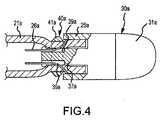
次に、図4のアブレーションカテーテルの実施形態に移るが、図1〜図3の実施形態に類似した要素には類似の参照番号が付されており、先端電極31aは、先端電極と一体である円筒形スカートの形態のプルリング25aを含むことがわかる(流体マニホールドは存在しない)。ハンドルアクチュエータ(図示せず)によってプルワイヤ26aを引くことで、遠位先端30aは第1の方向、またはその反対の第2の方向に、直接的に移動する。取付器具40aの圧迫リング41aは、装着シャフト37aに対して撓み及び圧迫変形可能なカテーテルシャフト21aを圧迫し、これらを共に固定する。 Turning now to the embodiment of the ablation catheter of FIG. 4, elements similar to those of the embodiment of FIGS. 1-3 are given like reference numerals and the
図5および図6に示されたアブレーションカテーテルの実施形態において、図1〜図3の実施形態に類似した要素には類似の参照符号が付されている。装着シャフト37bは、突出する環状リップは含まないが、代わりにその外側表面に、圧迫リング41bによって圧迫された撓み可能な伸縮性のカテーテルシャフト21bを把持する鉤状部43を含む。トリム接着剤44は、圧迫リング41bを覆い、電極プルリング25bと、カテーテルシャフト21bおよび流体マニホールド33bのそれぞれとの間を伸びている。トリム接着剤は、カテーテル20に、滑らかな外側表面を提供する。鉤状部43は、カテーテルシャフトを把持するために、他の特徴的構造または表面凹凸によって置き換えることができる。 In the embodiment of the ablation catheter shown in FIGS. 5 and 6, elements similar to those of the embodiment of FIGS. The mounting
撓み可能なアブレーションカテーテルの図7の実施形態において、図1〜図3の実施形態に類似した要素には類似の参照番号が付されており、装着シャフト37cは、その内側表面に、中に延伸するカテーテルシャフト21cの遠位端部分を把持する鉤状部45を含む。円筒形本体47、縁48およびそれを通る軸方向通路49を有するT字型補強部46は、カテーテルシャフトの中空内部23cに配置される。円筒形本体47は、鉤状部45に対してカテーテルシャフト21cを圧迫し、遠位先端30dをカテーテル20cにしっかりと取り付けるための、圧迫リングとして機能する。鉤状部45は、カテーテルシャフトを把持する他の特徴的構造または表面凹凸よって置き換えることができる。 In the embodiment of FIG. 7 of a deflectable ablation catheter, elements similar to those of the embodiment of FIGS. 1-3 are labeled with similar reference numbers and the mounting
本発明の多数の実施形態が示され記載されているが、それらに修正を加えたものも、依然として本願の特許請求の範囲内に含まれる。例えば、接続された2本のプルワイヤを有するプルリングの代わりに、3本、4本またはそれ以上のワイヤを外周のまわりに接続することができ、それらに対応するガイドチャネルをカテーテルシャフトに設け、対応する軸方向溝を装着シャフトに設けることができる。また、プルリングは電極として機能することができ、プルワイヤは、エネルギ源60からプルリングへエネルギを送出するようにエネルギを伝導する機能を持ち得る。取付器具は、互いに隣接して配置された複数の圧迫リングシステムを含むことができる。カテーテルシャフトへ滑らかな外側表面を提供するために、図2〜図3の実施形態で、トリム接着剤を使用することができる。
While a number of embodiments of the invention have been shown and described, modifications thereof are still within the scope of the claims. For example, instead of a pull ring with two connected pull wires, three, four or more wires can be connected around the outer circumference and corresponding guide channels are provided on the catheter shaft for An axial groove can be provided on the mounting shaft. The pull ring can also function as an electrode, and the pull wire can have the function of conducting energy to deliver energy from the
Claims (17)
Translated fromJapanese遠位端および中空内部を画定する撓み変形可能且つ圧迫変形可能なカテーテルシャフトと、
前記遠位端近傍で前記カテーテルシャフトのまわりに装着された撓みプルリングを備えるプルリングアセンブリと、
前記カテーテルシャフトの前記遠位端の遠位先端であって、先端部および装着シャフトを備える遠位先端と、
前記装着シャフトおよび前記カテーテルシャフトを一緒に圧迫する取付手段と
を備えており、
前記撓みプルリングは、前記取付手段と前記先端部の間の位置で前記カテーテルシャフトに装着されることを特徴とする医療用カテーテルアセンブリ。A medical catheter assembly comprising:
A deflectable and compression deformable catheter shaft defining a distal end and a hollow interior;
A pull ring assembly comprising a flexible pull ring mounted about the catheter shaft near the distal end;
A distal tip of the distal end of the catheter shaft, the distal tip comprising a tip and a mounting shaft;
Mounting means for compressing the mounting shaft and the catheter shaft together;
The medical catheter assemblyaccording to claim 1, wherein the flexible pull ring is attached to the catheter shaft at a position between the attachment means and the distal end portion .
請求項1に記載の医療用カテーテルアセンブリ。The medical catheter assembly according to claim 1, wherein the attachment means for compressing the mounting shaft and the catheter shaft together comprises a compression ring.
請求項2に記載の医療用カテーテルアセンブリ。The medical catheter assembly according to claim 2, wherein the compression ring is disposed about the catheter shaft to compress the catheter shaft against an outer surface of the mounting shaft.
請求項1〜3のいずれか一項に記載の医療用カテーテルアセンブリ。The medical catheter assembly according to any one of claims 1 to 3, wherein the pull ringassembly comprises a pull wire that extends through a channel in the catheter shaft into the hollow interior.
請求項1〜4のいずれか一項に記載の医療用カテーテルアセンブリ。The medical catheter assembly according to any one of claims 1 to 4, wherein the mounting shaft includes an axial groove on an outer surface thereof in which each pull wire extends.
前記装着シャフトは、その外側表面上に直径方向で互いに対向する位置に2本の軸方向溝を備える
請求項1〜5のいずれか一項に記載の医療用カテーテルアセンブリ。Two pull wires connected to the pull ring at positions facing each other in the diametrical direction;
The medical catheter assembly according to any one of claims 1 to 5, wherein the mounting shaft includes two axial grooves on the outer surface thereof at diametrically opposed positions.
前記取付手段は、前記装着シャフト上に外向きに突出する環状リップを備え、前記環状リップは前記圧迫リングを超えて前記遠位端へ向かう前記装着シャフトの動きを抑制する
請求項2〜6のいずれか一項に記載の医療用カテーテルアセンブリ。The mounting shaft has a free end within the hollow interior of the catheter shaft that is located further from the distal end than the compression ring;
The attachment means includes an annular lip projecting outwardly on the mounting shaft, and the annular lip suppresses movement of the mounting shaft toward the distal end beyond the compression ring. A medical catheter assembly according to any one of the preceding claims.
前記プルリングが前記圧縮リングに向かって動くことで、前記傾斜表面に圧迫を生じさせる
請求項2〜7のいずれか一項に記載の医療用カテーテルアセンブリ。The compression ring comprises an inclined surface facing the pull ring;
The medical catheter assembly according to any one of claims 2 to 7, wherein the pull ring moves toward the compression ring to cause compression on the inclined surface.
請求項1〜8のいずれか一項に記載の医療用カテーテルアセンブリ。The medical catheter assembly according to any one of claims 1 to 8, wherein the attachment means comprises means for extending outwardly on the mounting shaft to grip the catheter shaft.
請求項9に記載の医療用カテーテルアセンブリ。The medical catheter assembly according to claim 9, wherein the outwardly extending means comprises a surface protrusion.
請求項10に記載の医療用カテーテルアセンブリ。The medical catheter assembly according to claim 10, wherein the surface protrusion is a hook-shaped portion.
請求項2〜11のいずれか一項記載の医療用カテーテルアセンブリ。The medical catheter assembly according to any one of claims 2 to 11, comprising a trim adhesive covering the compression ring and extending between the pull ring and each of the catheter shaft and the distal tip.
請求項1〜12のいずれか一項に記載の医用療カテーテルアセンブリ。The medical care catheter assembly according to any one of claims 1 to 12, wherein the pull ring comprises an annular skirt that is integral with the distal tip.
請求項1〜13のいずれか一項に記載の医療用カテーテルアセンブリ。The medical tip assembly according to any one of claims 1 to 13, wherein the tip is a tip electrode.
遠位端および中空内部を画定する撓み変形可能且つ圧迫変形可能なカテーテルシャフトと、
前記遠位端近傍で前記カテーテルシャフトのまわりに装着された撓みプルリングおよびプルワイヤを備えるプルリングアセンブリと、
前記カテーテルシャフトの前記遠位端の遠位先端であって、先端電極および装着シャフトを備える遠位先端と、
前記装着シャフトおよび前記カテーテルシャフトを一緒に圧迫固定する圧迫リングを備える取付手段と
を備え、
前記撓みプルリングは、前記取付手段と前記先端電極の間の位置で前記カテーテルシャフトに装着されることを特徴とするアブレーションカテーテルアセンブリ。An ablation catheter assembly comprising:
A deflectable and compression deformable catheter shaft defining a distal end and a hollow interior;
A pull ring assembly comprising a flexible pull ring and a pull wire mounted about the catheter shaft near the distal end;
A distal tip of the distal end of the catheter shaft, the distal tip comprising a tip electrode and a mounting shaft;
Mounting meanscomprising a compression ring for compressing and fixing the mounting shaft and the catheter shaft together;
Wherein the deflection pull ring, said mounting means and said distal position by said ablation catheter assemblyyou, characterized in that it is mounted on the catheter shaft between the electrodes.
前記流体マニホールドおよび前記装着シャフトは一体であり、前記流体マニホールドは、前記流体マニホールドの外側表面の排出用開口部へ流体を送出するための送出チャネルを備える
請求項15に記載のアブレーションカテーテルアセンブリ。The distal tip further comprises a fluid manifold between the tip electrode and the mounting shaft;
16. The ablation catheter assembly according to claim 15, wherein the fluid manifold and the mounting shaft are integral, and the fluid manifold includes a delivery channel for delivering fluid to a discharge opening on an outer surface of the fluid manifold.
請求項16に記載のアブレーションカテーテルアセンブリ。The ablation catheter assembly of claim 16, wherein the fluid manifold comprises a plurality of delivery channels for delivering fluid to respective openings spaced around the outer surface of the fluid manifold.
Applications Claiming Priority (3)
| Application Number | Priority Date | Filing Date | Title |
|---|---|---|---|
| US11/963,393 | 2007-12-21 | ||
| US11/963,393US8226641B2 (en) | 2007-12-21 | 2007-12-21 | Medical catheter with deflection pull ring and distal tip attachment apparatus |
| PCT/US2008/083725WO2009082569A1 (en) | 2007-12-21 | 2008-11-17 | Medical catheter with deflection pull ring and distal tip attachment apparatus |
Publications (3)
| Publication Number | Publication Date |
|---|---|
| JP2011507605A JP2011507605A (en) | 2011-03-10 |
| JP2011507605A5 JP2011507605A5 (en) | 2011-10-13 |
| JP5386504B2true JP5386504B2 (en) | 2014-01-15 |
Family
ID=40789511
Family Applications (1)
| Application Number | Title | Priority Date | Filing Date |
|---|---|---|---|
| JP2010539565AExpired - Fee RelatedJP5386504B2 (en) | 2007-12-21 | 2008-11-17 | Medical catheter with flexible pull ring and distal tip attachment device |
Country Status (4)
| Country | Link |
|---|---|
| US (3) | US8226641B2 (en) |
| EP (1) | EP2190519B1 (en) |
| JP (1) | JP5386504B2 (en) |
| WO (1) | WO2009082569A1 (en) |
Families Citing this family (30)
| Publication number | Priority date | Publication date | Assignee | Title |
|---|---|---|---|---|
| CN102811669B (en)* | 2010-03-19 | 2016-01-06 | 山科精器株式会社 | Catheter for endoscope |
| ITMI20100341U1 (en)* | 2010-11-10 | 2012-05-11 | Finella Medical S P A | DEVICE WITH ELECTRO-CATHETER TO INDUCE A REVERSIBLE NEUROLESION |
| JP6441679B2 (en) | 2011-12-09 | 2018-12-19 | メタベンション インコーポレイテッド | Therapeutic neuromodulation of the liver system |
| US20140135745A1 (en) | 2011-12-15 | 2014-05-15 | Imricor Medical Systems, Inc. | Mri compatible handle and steerable sheath |
| US9757538B2 (en) | 2011-12-15 | 2017-09-12 | Imricor Medical Systems, Inc. | MRI compatible control handle for steerable sheath with audible, tactile and/or visual means |
| US9821143B2 (en) | 2011-12-15 | 2017-11-21 | Imricor Medical Systems, Inc. | Steerable sheath including elastomeric member |
| US8702647B2 (en) | 2012-04-19 | 2014-04-22 | Medtronic Ablation Frontiers Llc | Catheter deflection anchor |
| JP5348675B1 (en)* | 2012-05-30 | 2013-11-20 | 日本ライフライン株式会社 | Electrode catheter |
| DE112014001630T5 (en) | 2013-03-27 | 2015-12-24 | Semitec Corporation | Contact pressure sensor and manufacturing method therefor |
| AU2014274903B2 (en) | 2013-06-05 | 2019-03-07 | Medtronic Ireland Manufacturing Unlimited Company | Modulation of targeted nerve fibers |
| KR101374320B1 (en)* | 2013-10-15 | 2014-03-17 | 홍문기 | Steerable electrode catheter assembly |
| EP3417821B1 (en)* | 2013-10-28 | 2021-06-30 | St. Jude Medical, Cardiology Division, Inc. | Ablation catheter designs with enhanced diagnostic capabilities |
| JP2017504390A (en)* | 2013-12-24 | 2017-02-09 | セント・ジュード・メディカル,カーディオロジー・ディヴィジョン,インコーポレイテッド | A deflectable catheter body having a corrugated structure |
| WO2016071378A1 (en) | 2014-11-04 | 2016-05-12 | Koninklijke Philips N.V. | Steerable medical device, and use of a pull wire ring therein |
| CA2969129A1 (en) | 2014-12-03 | 2016-06-09 | Metavention, Inc. | Systems and methods for modulating nerves or other tissue |
| CN104825226A (en)* | 2015-05-04 | 2015-08-12 | 中国人民解放军总医院 | Large ablation head and ablation device |
| US10328250B2 (en) | 2015-07-02 | 2019-06-25 | Covellus Llc | Medical device adapter |
| US10814120B2 (en) | 2015-07-02 | 2020-10-27 | Covellus Llc | Modular medical device catheter system |
| US11660439B2 (en) | 2015-07-02 | 2023-05-30 | Covellus Llc | Modular medical device system |
| US10912922B2 (en) | 2015-07-02 | 2021-02-09 | Covellus Llc | Modular medical device catheter system |
| US10154905B2 (en) | 2015-08-07 | 2018-12-18 | Medtronic Vascular, Inc. | System and method for deflecting a delivery catheter |
| CA3015404A1 (en)* | 2016-02-26 | 2017-08-31 | Sunnybrook Research Institute | Imaging probe with rotatable core |
| US10524859B2 (en) | 2016-06-07 | 2020-01-07 | Metavention, Inc. | Therapeutic tissue modulation devices and methods |
| US20180242886A1 (en)* | 2017-02-28 | 2018-08-30 | St. Jude Medical International Holding S.À R.L. | Elastomeric moisture barrier for force sensor |
| EP3691732B1 (en)* | 2017-10-06 | 2025-05-21 | Boston Scientific Medical Device Limited | Reinforced sheath for a steerable sheath assembly |
| WO2020163678A1 (en)* | 2019-02-08 | 2020-08-13 | Covellus Llc | Modular medical device system |
| KR102385529B1 (en)* | 2019-08-02 | 2022-04-14 | 쥬베뉴 주식회사 | Epidural Catheter with RF generation function |
| US11723767B2 (en)* | 2019-08-15 | 2023-08-15 | Boston Scientific Scimed, Inc. | Medical device including attachable tip member |
| US20210093836A1 (en)* | 2019-09-30 | 2021-04-01 | Abiomed, Inc. | Collapsible catheter |
| US12232770B2 (en) | 2020-09-15 | 2025-02-25 | Medtronic, Inc. | Deflectable delivery system for implant delivery |
Family Cites Families (32)
| Publication number | Priority date | Publication date | Assignee | Title |
|---|---|---|---|---|
| LU77252A1 (en)* | 1976-05-06 | 1977-08-22 | ||
| US4471779A (en)* | 1976-08-25 | 1984-09-18 | Becton, Dickinson And Company | Miniature balloon catheter |
| US4778447A (en)* | 1983-05-20 | 1988-10-18 | Travenol European Research & Development Center | Connectors |
| US5114403A (en)* | 1989-09-15 | 1992-05-19 | Eclipse Surgical Technologies, Inc. | Catheter torque mechanism |
| US5273535A (en) | 1991-11-08 | 1993-12-28 | Ep Technologies, Inc. | Catheter with electrode tip having asymmetric left and right curve configurations |
| CA2109980A1 (en) | 1992-12-01 | 1994-06-02 | Mir A. Imran | Steerable catheter with adjustable bend location and/or radius and method |
| US5389073A (en) | 1992-12-01 | 1995-02-14 | Cardiac Pathways Corporation | Steerable catheter with adjustable bend location |
| US5391147A (en) | 1992-12-01 | 1995-02-21 | Cardiac Pathways Corporation | Steerable catheter with adjustable bend location and/or radius and method |
| US5462527A (en) | 1993-06-29 | 1995-10-31 | C.R. Bard, Inc. | Actuator for use with steerable catheter |
| US5715817A (en)* | 1993-06-29 | 1998-02-10 | C.R. Bard, Inc. | Bidirectional steering catheter |
| US5545200A (en) | 1993-07-20 | 1996-08-13 | Medtronic Cardiorhythm | Steerable electrophysiology catheter |
| US5431168A (en) | 1993-08-23 | 1995-07-11 | Cordis-Webster, Inc. | Steerable open-lumen catheter |
| US5882333A (en)* | 1994-05-13 | 1999-03-16 | Cardima, Inc. | Catheter with deflectable distal section |
| US5666970A (en) | 1995-05-02 | 1997-09-16 | Heart Rhythm Technologies, Inc. | Locking mechanism for catheters |
| US6113572A (en) | 1995-05-24 | 2000-09-05 | C. R. Bard, Inc. | Multiple-type catheter connection systems |
| US6090104A (en)* | 1995-06-07 | 2000-07-18 | Cordis Webster, Inc. | Catheter with a spirally wound flat ribbon electrode |
| US6840936B2 (en) | 1996-10-22 | 2005-01-11 | Epicor Medical, Inc. | Methods and devices for ablation |
| US5882233A (en) | 1997-02-26 | 1999-03-16 | Suntec & Co., Ltd. | Pin plug including conductive insert |
| JP3798928B2 (en)* | 1999-11-16 | 2006-07-19 | ペンタックス株式会社 | Connection structure of tube and base of endoscope treatment tool |
| US6926669B1 (en) | 2000-10-10 | 2005-08-09 | Medtronic, Inc. | Heart wall ablation/mapping catheter and method |
| US7258690B2 (en)* | 2003-03-28 | 2007-08-21 | Relievant Medsystems, Inc. | Windowed thermal ablation probe |
| WO2004086994A1 (en)* | 2003-03-28 | 2004-10-14 | C.R. Bard, Inc. | Method and apparatus for electrosurgical ablation |
| US7235070B2 (en) | 2003-07-02 | 2007-06-26 | St. Jude Medical, Atrial Fibrillation Division, Inc. | Ablation fluid manifold for ablation catheter |
| US7229437B2 (en) | 2003-09-22 | 2007-06-12 | St. Jude Medical, Atrial Fibrillation Division, Inc. | Medical device having integral traces and formed electrodes |
| NL1024658C2 (en)* | 2003-10-29 | 2005-05-02 | Univ Medisch Centrum Utrecht | Catheter and method, in particular for ablation and the like. |
| US7918851B2 (en) | 2005-02-14 | 2011-04-05 | Biosense Webster, Inc. | Irrigated tip catheter and method for manufacturing therefor |
| US7740616B2 (en) | 2005-03-29 | 2010-06-22 | Angiodynamics, Inc. | Implantable catheter and method of using same |
| US20070270679A1 (en) | 2006-05-17 | 2007-11-22 | Duy Nguyen | Deflectable variable radius catheters |
| US7662152B2 (en)* | 2006-06-13 | 2010-02-16 | Biosense Webster, Inc. | Catheter with multi port tip for optical lesion evaluation |
| US7988674B2 (en)* | 2006-10-30 | 2011-08-02 | Medtronic, Inc. | Externally releasable body portal anchors and systems |
| EP2381998B1 (en)* | 2008-12-31 | 2018-04-25 | St. Jude Medical, Atrial Fibrillation Division, Inc. | Optic-based contact sensing assembly and system |
| US8840583B2 (en)* | 2011-08-16 | 2014-09-23 | Syringex Medical, Inc. | Safety syringe |
- 2007
- 2007-12-21USUS11/963,393patent/US8226641B2/ennot_activeExpired - Fee Related
- 2008
- 2008-11-17EPEP08865469Apatent/EP2190519B1/ennot_activeNot-in-force
- 2008-11-17JPJP2010539565Apatent/JP5386504B2/ennot_activeExpired - Fee Related
- 2008-11-17WOPCT/US2008/083725patent/WO2009082569A1/enactiveApplication Filing
- 2012
- 2012-07-23USUS13/555,918patent/US9642985B2/ennot_activeExpired - Fee Related
- 2017
- 2017-05-03USUS15/585,195patent/US10478597B2/ennot_activeExpired - Fee Related
Also Published As
| Publication number | Publication date |
|---|---|
| EP2190519B1 (en) | 2013-01-16 |
| EP2190519A4 (en) | 2011-11-30 |
| US9642985B2 (en) | 2017-05-09 |
| US20170296787A1 (en) | 2017-10-19 |
| WO2009082569A1 (en) | 2009-07-02 |
| US10478597B2 (en) | 2019-11-19 |
| JP2011507605A (en) | 2011-03-10 |
| EP2190519A1 (en) | 2010-06-02 |
| US8226641B2 (en) | 2012-07-24 |
| US20090163915A1 (en) | 2009-06-25 |
| US20120330230A1 (en) | 2012-12-27 |
Similar Documents
| Publication | Publication Date | Title |
|---|---|---|
| JP5386504B2 (en) | Medical catheter with flexible pull ring and distal tip attachment device | |
| JP5449190B2 (en) | Medical catheter assembly with flexible pull ring and distal tip coupling mechanism | |
| EP1627598A3 (en) | Catheter having mapping assembly | |
| US20220160213A1 (en) | Endoscopic device with additional channel | |
| JP2011507605A5 (en) | ||
| WO2004060434A3 (en) | Deflecting catheter | |
| US20070232859A1 (en) | Endoscopic suction device | |
| EP1566141A4 (en) | Flexible tube of endoscope | |
| US6958050B1 (en) | Nasal/oral aspiration device | |
| JPH08131397A (en) | Hood for endoscope | |
| JP2016508405A (en) | Tracheostomy tube assembly and inner cannula | |
| JP2010213800A (en) | Catheter | |
| JP4648785B2 (en) | Endoscopic balloon catheter for endoscope | |
| WO2021100378A1 (en) | Endoscope clip system and method for producing same | |
| US20140358141A1 (en) | Electrosurgical pencil with a smoke evaporation tube | |
| JP3567600B2 (en) | Endoscope treatment instrument insertion channel | |
| US10092170B2 (en) | Insertion apparatus | |
| JP4611511B2 (en) | Endoscopic tube treatment device | |
| JP2001137180A (en) | Endoscope | |
| JP2003135379A (en) | Two-channel endoscope | |
| WO2022231921A3 (en) | Cannula assembly | |
| WO2021100379A1 (en) | Endoscope clip system | |
| JP5570379B2 (en) | Surgical endoscope device | |
| EP2758090A1 (en) | An electrosurgical pencil with a smoke evacuation tube |
Legal Events
| Date | Code | Title | Description |
|---|---|---|---|
| A521 | Request for written amendment filed | Free format text:JAPANESE INTERMEDIATE CODE: A523 Effective date:20110829 | |
| A621 | Written request for application examination | Free format text:JAPANESE INTERMEDIATE CODE: A621 Effective date:20110829 | |
| A131 | Notification of reasons for refusal | Free format text:JAPANESE INTERMEDIATE CODE: A131 Effective date:20121218 | |
| A977 | Report on retrieval | Free format text:JAPANESE INTERMEDIATE CODE: A971007 Effective date:20121220 | |
| A521 | Request for written amendment filed | Free format text:JAPANESE INTERMEDIATE CODE: A523 Effective date:20130318 | |
| TRDD | Decision of grant or rejection written | ||
| A01 | Written decision to grant a patent or to grant a registration (utility model) | Free format text:JAPANESE INTERMEDIATE CODE: A01 Effective date:20130924 | |
| A61 | First payment of annual fees (during grant procedure) | Free format text:JAPANESE INTERMEDIATE CODE: A61 Effective date:20131007 | |
| R150 | Certificate of patent or registration of utility model | Ref document number:5386504 Country of ref document:JP Free format text:JAPANESE INTERMEDIATE CODE: R150 Free format text:JAPANESE INTERMEDIATE CODE: R150 | |
| R250 | Receipt of annual fees | Free format text:JAPANESE INTERMEDIATE CODE: R250 | |
| R250 | Receipt of annual fees | Free format text:JAPANESE INTERMEDIATE CODE: R250 | |
| R250 | Receipt of annual fees | Free format text:JAPANESE INTERMEDIATE CODE: R250 | |
| LAPS | Cancellation because of no payment of annual fees |