JP5386372B2 - System and method for enhancing features of cardiac signals used for morphological identification - Google Patents
System and method for enhancing features of cardiac signals used for morphological identificationDownload PDFInfo
- Publication number
- JP5386372B2 JP5386372B2JP2009548345AJP2009548345AJP5386372B2JP 5386372 B2JP5386372 B2JP 5386372B2JP 2009548345 AJP2009548345 AJP 2009548345AJP 2009548345 AJP2009548345 AJP 2009548345AJP 5386372 B2JP5386372 B2JP 5386372B2
- Authority
- JP
- Japan
- Prior art keywords
- signal
- cardiac
- sensed
- component
- features
- Prior art date
- Legal status (The legal status is an assumption and is not a legal conclusion. Google has not performed a legal analysis and makes no representation as to the accuracy of the status listed.)
- Expired - Fee Related
Links
- 230000000747cardiac effectEffects0.000titleclaimsdescription192
- 238000000034methodMethods0.000titleclaimsdescription47
- 230000000877morphologic effectEffects0.000titledescription7
- 230000002708enhancing effectEffects0.000titledescription4
- 238000001514detection methodMethods0.000claimsdescription65
- 230000008859changeEffects0.000claimsdescription9
- 238000001914filtrationMethods0.000claimsdescription4
- 208000010125myocardial infarctionDiseases0.000claimsdescription4
- 230000004044responseEffects0.000description16
- 208000001871TachycardiaDiseases0.000description15
- 230000033764rhythmic processEffects0.000description14
- 206010049447TachyarrhythmiaDiseases0.000description13
- 230000008569processEffects0.000description11
- 230000002861ventricularEffects0.000description11
- 206010003119arrhythmiaDiseases0.000description10
- 238000007726management methodMethods0.000description9
- 230000004048modificationEffects0.000description9
- 238000012986modificationMethods0.000description9
- 210000005245right atriumAnatomy0.000description9
- 230000006793arrhythmiaEffects0.000description8
- 230000000694effectsEffects0.000description8
- 210000005240left ventricleAnatomy0.000description7
- 238000002560therapeutic procedureMethods0.000description7
- 230000001746atrial effectEffects0.000description6
- 230000008602contractionEffects0.000description6
- 230000000638stimulationEffects0.000description6
- 206010047302ventricular tachycardiaDiseases0.000description6
- 210000005241right ventricleAnatomy0.000description5
- 230000035939shockEffects0.000description5
- 238000011282treatmentMethods0.000description5
- 206010065342Supraventricular tachyarrhythmiaDiseases0.000description4
- 230000000875corresponding effectEffects0.000description4
- 239000002131composite materialSubstances0.000description3
- 210000003748coronary sinusAnatomy0.000description3
- 238000010586diagramMethods0.000description3
- 230000002169extracardiacEffects0.000description3
- 210000005246left atriumAnatomy0.000description3
- 230000001629suppressionEffects0.000description3
- 210000003462veinAnatomy0.000description3
- 230000004075alterationEffects0.000description2
- 230000015572biosynthetic processEffects0.000description2
- 210000005242cardiac chamberAnatomy0.000description2
- 238000005265energy consumptionMethods0.000description2
- 210000004165myocardiumAnatomy0.000description2
- 230000029058respiratory gaseous exchangeEffects0.000description2
- 230000005236sound signalEffects0.000description2
- 206010049765BradyarrhythmiaDiseases0.000description1
- 206010007558Cardiac failure chronicDiseases0.000description1
- 208000027418Wounds and injuryDiseases0.000description1
- 230000002159abnormal effectEffects0.000description1
- 230000004913activationEffects0.000description1
- 230000003044adaptive effectEffects0.000description1
- 238000007792additionMethods0.000description1
- 230000008901benefitEffects0.000description1
- 239000008280bloodSubstances0.000description1
- 210000004369bloodAnatomy0.000description1
- 208000006218bradycardiaDiseases0.000description1
- 206010061592cardiac fibrillationDiseases0.000description1
- 238000009125cardiac resynchronization therapyMethods0.000description1
- 238000013194cardioversionMethods0.000description1
- 230000015556catabolic processEffects0.000description1
- 238000004891communicationMethods0.000description1
- 230000002596correlated effectEffects0.000description1
- 230000006378damageEffects0.000description1
- 238000006731degradation reactionMethods0.000description1
- 201000010099diseaseDiseases0.000description1
- 208000037265diseases, disorders, signs and symptomsDiseases0.000description1
- 230000007613environmental effectEffects0.000description1
- 230000002600fibrillogenic effectEffects0.000description1
- 230000004927fusionEffects0.000description1
- 230000036541healthEffects0.000description1
- 210000002837heart atriumAnatomy0.000description1
- 210000005003heart tissueAnatomy0.000description1
- 238000002513implantationMethods0.000description1
- 230000006872improvementEffects0.000description1
- 208000014674injuryDiseases0.000description1
- 230000001788irregularEffects0.000description1
- 239000011159matrix materialSubstances0.000description1
- 230000003183myoelectrical effectEffects0.000description1
- 230000007170pathologyEffects0.000description1
- 230000007310pathophysiologyEffects0.000description1
- 230000000737periodic effectEffects0.000description1
- 230000004962physiological conditionEffects0.000description1
- 238000005086pumpingMethods0.000description1
- 238000010791quenchingMethods0.000description1
- 230000009467reductionEffects0.000description1
- 230000000241respiratory effectEffects0.000description1
- 230000001020rhythmical effectEffects0.000description1
- 238000010187selection methodMethods0.000description1
- 238000004088simulationMethods0.000description1
- 210000002027skeletal muscleAnatomy0.000description1
- 230000004936stimulating effectEffects0.000description1
- 210000001321subclavian veinAnatomy0.000description1
- 210000001519tissueAnatomy0.000description1
- 210000002620vena cava superiorAnatomy0.000description1
Images


Classifications
- A—HUMAN NECESSITIES
- A61—MEDICAL OR VETERINARY SCIENCE; HYGIENE
- A61B—DIAGNOSIS; SURGERY; IDENTIFICATION
- A61B5/00—Measuring for diagnostic purposes; Identification of persons
- A61B5/24—Detecting, measuring or recording bioelectric or biomagnetic signals of the body or parts thereof
- A61B5/316—Modalities, i.e. specific diagnostic methods
- A61B5/318—Heart-related electrical modalities, e.g. electrocardiography [ECG]
- A61B5/346—Analysis of electrocardiograms
- A61B5/349—Detecting specific parameters of the electrocardiograph cycle
- A61B5/35—Detecting specific parameters of the electrocardiograph cycle by template matching
- A—HUMAN NECESSITIES
- A61—MEDICAL OR VETERINARY SCIENCE; HYGIENE
- A61B—DIAGNOSIS; SURGERY; IDENTIFICATION
- A61B5/00—Measuring for diagnostic purposes; Identification of persons
- A61B5/72—Signal processing specially adapted for physiological signals or for diagnostic purposes
- A61B5/7203—Signal processing specially adapted for physiological signals or for diagnostic purposes for noise prevention, reduction or removal
- A—HUMAN NECESSITIES
- A61—MEDICAL OR VETERINARY SCIENCE; HYGIENE
- A61B—DIAGNOSIS; SURGERY; IDENTIFICATION
- A61B5/00—Measuring for diagnostic purposes; Identification of persons
- A61B5/72—Signal processing specially adapted for physiological signals or for diagnostic purposes
- A61B5/7235—Details of waveform analysis
- A61B5/7264—Classification of physiological signals or data, e.g. using neural networks, statistical classifiers, expert systems or fuzzy systems
- A—HUMAN NECESSITIES
- A61—MEDICAL OR VETERINARY SCIENCE; HYGIENE
- A61B—DIAGNOSIS; SURGERY; IDENTIFICATION
- A61B5/00—Measuring for diagnostic purposes; Identification of persons
- A61B5/24—Detecting, measuring or recording bioelectric or biomagnetic signals of the body or parts thereof
- A61B5/316—Modalities, i.e. specific diagnostic methods
- A61B5/318—Heart-related electrical modalities, e.g. electrocardiography [ECG]
- A61B5/346—Analysis of electrocardiograms
- A61B5/349—Detecting specific parameters of the electrocardiograph cycle
- A61B5/363—Detecting tachycardia or bradycardia
- A—HUMAN NECESSITIES
- A61—MEDICAL OR VETERINARY SCIENCE; HYGIENE
- A61N—ELECTROTHERAPY; MAGNETOTHERAPY; RADIATION THERAPY; ULTRASOUND THERAPY
- A61N1/00—Electrotherapy; Circuits therefor
- A61N1/18—Applying electric currents by contact electrodes
- A61N1/32—Applying electric currents by contact electrodes alternating or intermittent currents
- A61N1/36—Applying electric currents by contact electrodes alternating or intermittent currents for stimulation
- A61N1/362—Heart stimulators
- A61N1/37—Monitoring; Protecting
- A61N1/371—Capture, i.e. successful stimulation
- G—PHYSICS
- G16—INFORMATION AND COMMUNICATION TECHNOLOGY [ICT] SPECIALLY ADAPTED FOR SPECIFIC APPLICATION FIELDS
- G16H—HEALTHCARE INFORMATICS, i.e. INFORMATION AND COMMUNICATION TECHNOLOGY [ICT] SPECIALLY ADAPTED FOR THE HANDLING OR PROCESSING OF MEDICAL OR HEALTHCARE DATA
- G16H50/00—ICT specially adapted for medical diagnosis, medical simulation or medical data mining; ICT specially adapted for detecting, monitoring or modelling epidemics or pandemics
- G16H50/20—ICT specially adapted for medical diagnosis, medical simulation or medical data mining; ICT specially adapted for detecting, monitoring or modelling epidemics or pandemics for computer-aided diagnosis, e.g. based on medical expert systems
Landscapes
- Health & Medical Sciences (AREA)
- Life Sciences & Earth Sciences (AREA)
- Engineering & Computer Science (AREA)
- Physics & Mathematics (AREA)
- Biophysics (AREA)
- Heart & Thoracic Surgery (AREA)
- Cardiology (AREA)
- Veterinary Medicine (AREA)
- Public Health (AREA)
- General Health & Medical Sciences (AREA)
- Signal Processing (AREA)
- Animal Behavior & Ethology (AREA)
- Artificial Intelligence (AREA)
- Pathology (AREA)
- Biomedical Technology (AREA)
- Surgery (AREA)
- Medical Informatics (AREA)
- Molecular Biology (AREA)
- Psychiatry (AREA)
- Physiology (AREA)
- Computer Vision & Pattern Recognition (AREA)
- Mathematical Physics (AREA)
- Evolutionary Computation (AREA)
- Fuzzy Systems (AREA)
- Electrotherapy Devices (AREA)
- Measuring Pulse, Heart Rate, Blood Pressure Or Blood Flow (AREA)
Abstract
Description
Translated fromJapanese本発明は、一般に、医療装置に関し、より具体的には、心臓信号の形態学的分析に基づいて心臓事象を分類するために使用される心臓装置および方法に関する。 The present invention relates generally to medical devices, and more particularly to cardiac devices and methods used to classify cardiac events based on morphological analysis of cardiac signals.
正常に機能している心臓は、律動収縮を引き起こし、全身に血液をポンピングすることができる。しかし、疾病や負傷が原因で心拍が不規則になってポンプ効率が低下することがある。不整脈は、様々な生理的状態および疾患過程から生じる心拍の不規則性を表すために使用される一般用語である。植込み型ペースメーカーや細動除去器などの心調律管理システムは、重篤な不整脈を有する患者の有効な処置として採用されている。これらのシステムは、典型的に、心臓からの電気信号を感知する回路網と、心臓に電気刺激パルスを供給するパルス発生器とを含む。患者の心臓の中に延出するリードは、不整脈を処置する様々な治療法に従って、心臓の電気信号を感知して刺激パルスを心臓に供給する心筋に接している電極に接続される。 A normally functioning heart can cause rhythmic contractions and pump blood throughout the body. However, due to illness or injury, the heart rate may become irregular and pump efficiency may be reduced. Arrhythmia is a general term used to describe heart rate irregularities resulting from various physiological conditions and disease processes. Cardiac rhythm management systems such as implantable pacemakers and defibrillators have been adopted as an effective treatment for patients with severe arrhythmias. These systems typically include circuitry that senses electrical signals from the heart and a pulse generator that provides electrical stimulation pulses to the heart. Leads extending into the patient's heart are connected to electrodes in contact with the myocardium that sense the heart's electrical signals and deliver stimulation pulses to the heart in accordance with various therapies for treating arrhythmias.
心調律管理システムは、組織の収縮を引き起こす心臓組織を刺激することによって心臓をペーシングすることができる。ペースメーカーは、心臓のポンピング効率を維持する収縮調律の発生時に心臓を助けるべく、タイミングよく一連の低エネルギーペースパルスを供給する。ペーシングパルスが心臓を「捕捉」しているかどうか、および収縮を引き起こしているかどうかを検出することによって、心調律管理システムは、捕捉を確実に生じさせる最適エネルギー消費量に対応するように、ペースパルスのエネルギーレベルを調整することができる。ペースパルスは、収縮を引き起こすために、最小エネルギー値または捕捉閾値を上回らなければならない。ペースパルスは、捕捉閾値を大幅に上回る消費エネルギーなしで、心臓の捕捉を刺激するに十分なエネルギーを有することが望ましい。 A cardiac rhythm management system can pace the heart by stimulating the heart tissue causing tissue contraction. The pacemaker delivers a series of low energy pace pulses in a timely manner to assist the heart in the event of contraction rhythms that maintain the pumping efficiency of the heart. By detecting whether the pacing pulse is “capturing” the heart and causing a contraction, the cardiac rhythm management system allows the pace pulse to respond to the optimal energy consumption that will ensure capture. The energy level can be adjusted. The pace pulse must exceed the minimum energy value or capture threshold to cause contraction. Desirably, the pace pulse has sufficient energy to stimulate capture of the heart without energy consumption significantly exceeding the capture threshold.
また、心調律管理システムは、様々な段階的治療を用いて異常な頻脈性不整脈を検出し終了させることができる。これらの段階的治療は、反頻脈性不整脈ペーシング(ATP)から頻脈性不整脈または細動を終了させるための高エネルギーショックの供給にまで及んでいる。これらの処置を効果的に提供するためには、まずCRM装置が発生している不整脈のタイプを識別しなければならない。 Also, the cardiac rhythm management system can detect and terminate abnormal tachyarrhythmias using various staged treatments. These phased therapies range from anti-tachyarrhythmia pacing (ATP) to the delivery of high energy shocks to end tachyarrhythmia or fibrillation. In order to effectively provide these treatments, the type of arrhythmia that the CRM device is generating must first be identified.
捕捉や頻脈性不整脈事象などの様々な心臓事象の検出は、電気記録図(EGM)または心電図(ECG)などの心臓信号の形態を分析することによって実施することができる。形態学的分析は、心臓信号における心臓信号特徴の有無および位置のうちの少なくとも一つを判断することを含んでもよい。心臓事象の検出に使用される心臓信号特徴が比較的安定しており、かつ他の信号特徴およびノイズと区別することができるとき、この種の分析は簡素化される。 Detection of various cardiac events, such as capture and tachyarrhythmia events, can be performed by analyzing the morphology of cardiac signals such as electrograms (EGM) or electrocardiograms (ECG). Morphological analysis may include determining at least one of the presence and location of cardiac signal features in the cardiac signal. This type of analysis is simplified when the cardiac signal features used to detect cardiac events are relatively stable and can be distinguished from other signal features and noise.
様々な心臓事象の分類に使用される心臓信号特徴の検出を強調するシステムおよび方法が必要である。本発明は、これらおよび他の必要性を満たすものである。 What is needed is a system and method that enhances the detection of cardiac signal features that are used to classify various cardiac events. The present invention fulfills these and other needs.
本発明は、感知された信号の形態学的分析に基づいて心臓事象を分類するために使用される方法および装置を対象とする。本発明の一実施形態は、心臓事象を分類する方法にかかわる。方法は、心臓信号成分およびノイズ信号成分とを備える信号を感知することを含む。感知された信号は、心臓信号成分の形態を選択的に(preferentially)変更するために処理される。心臓信号成分の変更された形態は、心臓信号成分の一つ以上の特徴の検出を強調する。心臓信号成分の一つ以上の特徴が検出され、信号事象が検出された特徴を用いて分類される。 The present invention is directed to methods and apparatus used to classify cardiac events based on morphological analysis of sensed signals. One embodiment of the invention relates to a method for classifying cardiac events. The method includes sensing a signal comprising a cardiac signal component and a noise signal component. The sensed signal is processed to selectively change the form of the cardiac signal component. The modified form of the cardiac signal component emphasizes the detection of one or more features of the cardiac signal component. One or more features of the cardiac signal component are detected and a signal event is classified using the detected features.
ある実施において、感知された信号を処理することは、適応性のある信号処理パラメータを用いて感知された信号を処理することを含む。信号処理パラメータは、自動的に決定することも、医師によって手動で決定することもできる。たとえば、信号処理パラメータは、心臓信号成分の一つ以上の望ましい特徴を強調するように選択することも、心臓信号成分の一つ以上の望ましくない特徴を抑制するように選択することもできる。 In some implementations, processing the sensed signal includes processing the sensed signal using adaptive signal processing parameters. The signal processing parameters can be determined automatically or manually by a physician. For example, the signal processing parameters can be selected to emphasize one or more desirable features of the cardiac signal component, or can be selected to suppress one or more undesirable features of the cardiac signal component.
一態様によれば、信号処理パラメータは、心臓発作による心拍とテンプレートの心拍との間の相関係数を強調するように決定することができる。
本発明の別の態様は、心臓信号成分の一つ以上の望ましくない特徴を検出すること、心臓信号成分の望ましくない成分を抑制する信号処理パラメータを決定することを含む。たとえば、望ましくない特徴は、勾配解析または曲率解析を用いて検出することができる。According to one aspect, the signal processing parameters can be determined to emphasize the correlation coefficient between the heartbeat due to the heart attack and the heartbeat of the template.
Another aspect of the invention includes detecting one or more undesirable features of the cardiac signal component and determining signal processing parameters that suppress the undesirable component of the cardiac signal component. For example, undesired features can be detected using gradient analysis or curvature analysis.
望ましくない特徴は検出すること、ペーシングプロトコル(たとえば、頻脈性不整脈発作をシミュレートするためのAAIペーシング)を用いて発生される信号に基づいて信号処理パラメータを強調すること、および保存された心臓信号に基づいて信号処理パラメータを使用することのうちの少なくとも一つを行うことができる。 Undesirable features are detected, signal processing parameters are enhanced based on signals generated using a pacing protocol (eg, AAI pacing to simulate tachyarrhythmia attacks), and a stored heart At least one of using signal processing parameters based on the signal can be performed.
様々なアプリケーションによれば、変更された心臓信号成分を用いて分類される心臓事象は、心臓ペーシング応答および頻脈性不整脈発作のうちの少なくとも一つを含んでもよい。 According to various applications, cardiac events that are classified using the altered cardiac signal component may include at least one of a cardiac pacing response and a tachyarrhythmia episode.
本発明の別の実施形態は、心臓事象を分類するために使用される医療システムを対象とする。このシステムは、心臓信号成分およびノイズ成分を含む信号を感知するように構成された感知回路を含む。信号処理回路は、感知された信号を処理して感知された信号の心臓信号成分の形態を選択的に変更するように構成される。変更された心臓信号成分は、心臓信号成分の一つ以上の特徴の検出を強調する。特徴検出器が、心臓信号成分の一つ以上の特徴を検出するように構成される。心臓事象プロセッサが、検出された特徴を用いて心臓事象を分類するように構成される。 Another embodiment of the invention is directed to a medical system used to classify cardiac events. The system includes a sensing circuit configured to sense a signal that includes a cardiac signal component and a noise component. The signal processing circuit is configured to process the sensed signal to selectively change the form of the cardiac signal component of the sensed signal. The altered cardiac signal component enhances detection of one or more features of the cardiac signal component. A feature detector is configured to detect one or more features of the cardiac signal component. A cardiac event processor is configured to classify cardiac events using the detected features.
心臓信号成分を変更するためにフィルタを使用することができる。一例において、フィルタは、約3Hzのハイパスコーナー周波数と約100Hzのローパスコーナー周波数とを含む。システムは、感知された信号のノイズ成分を抑制するために、感知された信号をフィルタ処理するように構成されたノイズフィルタをさらに含んでもよい。 A filter can be used to alter the cardiac signal component. In one example, the filter includes a high pass corner frequency of about 3 Hz and a low pass corner frequency of about 100 Hz. The system may further include a noise filter configured to filter the sensed signal to suppress a noise component of the sensed signal.
信号処理回路のパラメータは、人口データに由来するものであってもよく、患者の個々の特性に基づくものであってもよい。信号処理回路のパラメータは、装置によって自動的に適合されてもよく、医師によってプログラムされてもよい。 The parameters of the signal processing circuit may be derived from population data or may be based on individual characteristics of the patient. The parameters of the signal processing circuit may be automatically adapted by the device or programmed by the physician.
一実施によれば、信号処理回路は、信号処理ユニットのバンクを備える。信号処理ユニットの各々は、関連する信号処理パラメータを有すること、および特定のタイプの心臓事象を認識または分類するように最適化されることのうちの少なくとも一つであってもよい。 According to one implementation, the signal processing circuit comprises a bank of signal processing units. Each of the signal processing units may be at least one of having an associated signal processing parameter and being optimized to recognize or classify a particular type of cardiac event.
本発明の上記の要約は、本発明の各実施形態やすべての実施を説明するものではない。本発明の長所および功績は、本発明をより完全に理解するとともに、添付図面を併用し以下の詳細説明および特許請求の範囲を参照することによって明らかになり評価されよう。 The above summary of the present invention is not intended to describe each embodiment or every implementation of the present invention. The advantages and merit of the present invention will become apparent and appreciated by a more complete understanding of the present invention and by reference to the following detailed description and claims in conjunction with the accompanying drawings.
本発明は様々な修正形態および変更形態が可能であり、その明細が図面に例として示されており、以下で詳しく説明されることになる。ただし、本発明は、本発明を記載された特定の実施形態に限定するものではないことを理解されるべきである。本発明は、添付の特許請求の範囲によって規定されるように、本発明の範囲に包含されるすべての修正形態、等効物、および代替形態を対象とするものである。 The invention is capable of various modifications and variations, the details of which are illustrated by way of example in the drawings and will be described in detail below. However, it should be understood that the invention is not limited to the specific embodiments described. The invention is intended to cover all modifications, equivalents, and alternatives falling within the scope of the invention as defined by the appended claims.
例示された実施形態についての以下の説明では、本明細書の一部を形成する添付図が参照され、添付図には本発明が実施されうる様々な実施形態が例として示される。本発明の範囲から逸脱することなく、他の実施形態が利用されてもよく、構造的よび機能的変更がなされてもよいことを理解されるべきである。 In the following description of the illustrated embodiments, reference is made to the accompanying drawings that form a part hereof, and in which are shown by way of illustration various embodiments in which the invention may be practiced. It should be understood that other embodiments may be utilized and structural and functional changes may be made without departing from the scope of the present invention.
心臓ペーシング応答事象および頻脈性不整脈事象のうちの少なくとも一つを含む、様々な心臓事象および心臓状態のうちの少なくとも一つの検出は、心臓が生成する心臓信号の形態学的分析によって達成することができる。心臓信号は、ペースメーカー、除細動器、またはその他のタイプの心調律管理システムに結合された植込み電極を介して得ることができる。様々なタイプの心臓事象は、心臓事象のタイプを分類するのに使用できる定在的な心臓信号特徴に関連する。 Detection of at least one of a variety of cardiac events and conditions, including at least one of a cardiac pacing response event and a tachyarrhythmia event, is achieved by morphological analysis of the cardiac signal generated by the heart Can do. The cardiac signal can be obtained via an implanted electrode coupled to a pacemaker, defibrillator, or other type of cardiac rhythm management system. Various types of cardiac events are associated with standing cardiac signal characteristics that can be used to classify the types of cardiac events.
心臓事象を分類するのに使用される心臓信号特徴の検出は、心臓信号の形態学的特性次第で比較的困難となり得る。たとえば、事象識別に使用される特徴に時間的に近接して現れる望ましくない心臓信号特徴は問題である。これらの望ましくない特徴は、事象識別に使用される特徴の識別に変動をもたらす。たとえば、心臓事象識別が心臓信号ピークの振幅およびタイミングに基づいて行なわれる場合、単一の鋭いピークを表わす心臓信号が望ましい。ダブルピークや扁平なピークの存在は、事象識別においてピーク座標および対応する誤差を決定する際に変動をもたらす可能性がある。 Detection of cardiac signal features used to classify cardiac events can be relatively difficult depending on the morphological characteristics of the cardiac signal. For example, undesirable cardiac signal features that appear in time proximity to features used for event identification are problematic. These undesirable features lead to variations in the identification of features used for event identification. For example, if cardiac event identification is based on the amplitude and timing of cardiac signal peaks, a cardiac signal that represents a single sharp peak is desirable. The presence of double peaks or flat peaks can cause variations in determining peak coordinates and corresponding errors in event identification.
図1のフローグラフは、一部の実施形態に従って特徴の検出を強調するために信号処理を用いた心臓事象識別を含む方法を示す。この方法は、心臓信号成分およびノイズ信号成分を含む信号を感知すること(110)を含む。感知された信号は、心臓電気活動などの電気信号源、あるいは圧力信号、呼吸信号、または心音信号などの非電気的信号源に由来してもよい。感知された信号は、心臓信号成分の形態を選択的に変更するように処理される(120)。心臓信号成分の選択的変更は、たとえば、心臓信号成分の一つ以上の特徴を強調すること、および心臓信号成分の一つ以上の望ましくない特徴を抑制することのうちの少なくとも一つのための信号処理を含んでもよい。心臓信号成分の選択的変更は、ノイズ成分を必ずしも修正しない。一部の実施において、ノイズ成分は、別の信号処理ステップでフィルタ処理される。心臓信号成分の変更後、心臓信号成分中の一つ以上の特徴が検出される(130)。心臓事象は、検出された特徴を用いて識別される(140)。 The flow graph of FIG. 1 illustrates a method that includes cardiac event identification using signal processing to enhance feature detection in accordance with some embodiments. The method includes sensing 110 a signal that includes a cardiac signal component and a noise signal component. The sensed signal may be derived from an electrical signal source, such as cardiac electrical activity, or a non-electrical signal source, such as a pressure signal, respiratory signal, or heart sound signal. The sensed signal is processed 120 to selectively change the morphology of the cardiac signal component. The selective alteration of the cardiac signal component is, for example, a signal for at least one of enhancing one or more features of the cardiac signal component and suppressing one or more undesirable features of the cardiac signal component. Processing may be included. Selective alteration of the cardiac signal component does not necessarily correct the noise component. In some implementations, the noise component is filtered in a separate signal processing step. After altering the cardiac signal component, one or more features in the cardiac signal component are detected (130). A cardiac event is identified 140 using the detected features.
心臓電極、圧力センサ、呼吸センサ、加速度計、または他のセンサなど、植込み型または患者外部のセンサを介して感知される信号は、一般に、心臓信号成分に重畳されたノイズ成分を含む。たとえば、感知された信号が心臓活動に関係している場合、結果として生じた複合信号にはノイズ信号成分も存在するので、複合信号は心臓活動を必ずしも正確に表わすものではない。この説明では、ノイズ信号は心臓の活動以外の信号源に由来する信号である。ノイズ源は、60Hzの電源ラインノイズ、骨格筋に由来する筋電位、運動アーチファクト、およびその他のノイズ源のうちの少なくとも一つなどの環境ノイズを含み得る。ノイズのない、あるいはノイズレベルの低い「純粋な」心臓信号成分を実現するために心臓信号からノイズを除去することに多くの努力が向けられてきた。ノイズの抑制は、心臓事象を分類するために感知された信号の形態学的分析を容易にするために採用される一手法である。たとえば、ノイズ成分をフィルタ処理することによって、感知された信号の信号対ノイズ比を改善することにより、特徴の検出を強調することができる。 A signal sensed via an implantable or patient-external sensor, such as a cardiac electrode, pressure sensor, respiration sensor, accelerometer, or other sensor, generally includes a noise component superimposed on the cardiac signal component. For example, if the sensed signal is related to cardiac activity, the composite signal does not necessarily accurately represent cardiac activity because the resulting composite signal also has a noise signal component. In this description, the noise signal is a signal derived from a signal source other than the heart activity. Noise sources may include environmental noise, such as at least one of 60 Hz power line noise, myoelectric potential from skeletal muscle, motor artifacts, and other noise sources. Much effort has been devoted to removing noise from the heart signal to achieve a “pure” heart signal component that is free of noise or has a low noise level. Noise suppression is one technique employed to facilitate morphological analysis of sensed signals to classify cardiac events. For example, feature detection can be enhanced by improving the signal-to-noise ratio of the sensed signal by filtering the noise component.
ノイズ抑制法は、心臓信号と不要な源からの信号成分とを結合する信号から心臓信号を明らかにしようとするものである。本発明の方法は、感知された信号におけるノイズを抑制するためよりもむしろ信号特徴の検出を強調するために感知された信号の心臓信号成分を選択的に修正することを目的としている。本明細書において様々な実施形態で示されるような心臓信号成分の修正は、ノイズ抑制過程の有無にかかわらず実施することができる。たとえば、本発明の信号処理技術は、感知された信号の心臓信号成分に存在する信号特徴の検出を強調するために、心臓信号成分の形状を変えるように適用することができる。 Noise suppression attempts to reveal the heart signal from a signal that combines the heart signal with signal components from unwanted sources. The method of the present invention aims to selectively modify the cardiac signal component of the sensed signal to enhance detection of signal features rather than to suppress noise in the sensed signal. Modification of the cardiac signal component as shown in various embodiments herein can be performed with or without a noise suppression process. For example, the signal processing techniques of the present invention can be applied to alter the shape of the cardiac signal component to enhance detection of signal features present in the cardiac signal component of the sensed signal.
本発明の実施形態に従って心臓信号の特徴を強調する信号処理は、一つ以上の信号プロセッサを用いて心臓電極を介して感知された信号を処理することによって実現することができる。図2Aおよび2Bのグラフは、特徴の検出を強調するための心臓信号成分の修正を示す。図2Aは、比較的鋭い負のピーク220と扁平な正のピーク230を表わす心臓信号210を示す。図2Bは、正のピーク250を鋭くするために信号処理後に修正された心臓信号240を示す。 Signal processing that enhances the characteristics of a cardiac signal in accordance with embodiments of the present invention can be accomplished by processing the signal sensed through the cardiac electrode using one or more signal processors. The graphs of FIGS. 2A and 2B show the modification of the cardiac signal component to enhance feature detection. FIG. 2A shows a
特徴の検出を強調するために信号を処理すると、心臓事象がより正確に識別される。図3A〜3Dは、心臓ペーシングに対する捕捉応答の正確な識別の改善を示す。図3Aおよび3Cは、ペーシングに続いて感知された多くの心臓信号305、306を示す。捕捉応答は、検出ウィンドウ310、320内で発生する正および負の信号ピークによって識別される。図3Bおよび3Dの円311、321は、様々な信号305、306の心臓信号ピーク位置を示す。図3Aから分かるように、未処理信号305は、初めは、やや扁平な形態またはダブルピーク形態を有する正のピークを表わす。この形態は、捕捉検出ウィンドウ310から外れた正のピーク312を有する信号群となる。捕捉検出ウィンドウ310から外れたピーク312を有する信号は、捕捉応答以外の応答として誤って識別されることになる。 Processing the signal to enhance feature detection identifies cardiac events more accurately. 3A-3D show improved accuracy identification of captured responses to cardiac pacing. 3A and 3C show a number of
処理後の心臓信号306は、図3Cおよび3Dに示されるように、正のピーク検出を強調する変更された形態を表わす。図3Cに示される信号306は、信号306の形態を変更するためにフィルタなどによって処理されている。図3Dは、正のピーク311の位置が捕捉検出ウィンドウ310内に現在含まれており、正確な捕捉検出が得られることを示す。 The processed
特徴の検出を強調するために信号を処理できるシステムは、植込み型細動除去器、ペースメーカー、または再同期装置などの心調律管理(CRM)装置で実現することができる。本システムはマイクロプロセッサベースのアーキテクチャを有する装置に関連して説明されているが、CRM装置は、必要に応じて、ロジックベースの集積回路アーキテクチャで実現することもできると理解されよう。さらに、本発明の方法は、患者外部の装置、または患者外部の部品と患者植込み型部品の両方を組み入れたシステムで実現することができる。 A system that can process a signal to enhance feature detection can be implemented with a cardiac rhythm management (CRM) device such as an implantable defibrillator, pacemaker, or resynchronizer. Although the system has been described with reference to a device having a microprocessor-based architecture, it will be understood that the CRM device can also be implemented with a logic-based integrated circuit architecture, if desired. Furthermore, the method of the present invention can be implemented in a patient-external device or system incorporating both patient-external and patient-implantable components.
ここで図面の図4を参照すると、本発明に従って特徴の検出を強調するために、信号処理を実行するのに使用できるCRM装置が示されている。図4の心調律管理システムは、リードシステム402に電気的および物理的に結合されたCRM装置400を含む。CRM装置400のハウジングおよびヘッダのうちの少なくとも一つには、心臓に電気刺激エネルギーを供給し心臓の電気的活動を感知するために使用される一つ以上の電極408、409を組み入れることができる。CRM装置400では、ハウジングの全部または一部を缶電極409として利用することができる。装置400は、たとえば、装置400のヘッダまたはハウジングの表面に配置された不関電極408を含んでいてもよい。装置400が缶電極409と不関電極408の両方を含む場合、電極408、409は、典型的に、互いに電気的に絶縁される。 Referring now to FIG. 4 of the drawings, there is shown a CRM device that can be used to perform signal processing to enhance feature detection in accordance with the present invention. The cardiac rhythm management system of FIG. 4 includes a
リードシステム402は、心臓不整脈を処置するために、ある所定の条件下で、心臓によって発生される電気心臓信号を検出し、かつ電気エネルギーを心臓に供給するために使用される植込み型電極を含む。リードシステム402は、ペーシング、感知、および除細動のうちの少なくとも一つに使用される一つ以上の電極を含んでもよい。図4に示される実施形態において、リードシステム402は、心臓内右心室(RV)リードシステム404、心臓内右心房(RA)リードシステム405、心臓内左心室(LV)リードシステム406、および心臓外左心房(LA)リードシステム410を含む。図4のリードシステム402は、本明細書に記載された信号特徴強調手法に関連して使用できる一実施形態を示す。他のリードおよび電極のうちの少なくとも一つが追加的または代替的に使用されてもよい。 The
リードシステム402は、患者の心臓に挿入されて心筋に電気的に結合される心臓内リード404、405、406を含んでもよい。心臓内リード404、405、406は、心臓の電気的活動を感知し、心臓の様々な不整脈を処置するためにペーシングパルスおよび除細動ショックのうちの少なくとも一つなどにより心臓に電気刺激エネルギーを供給する、心臓内に配置可能な様々な電極を含む。 The
図4に示されるように、リードシステム402は、一つ以上の心腔を感知してペーシングするために心臓の外側に位置する心外膜電極などの電極を有する一本以上の心臓外リード410を含んでもよい。 As shown in FIG. 4, the
図4に示される右心室リードシステム404は、SVCコイル416、RVコイル414、RVリング電極411、およびRV先端電極412を含む。右心室リードシステム404は、右心房420を通り、右心室419の中に延出する。具体的には、RV先端電極412、RVリング電極411、およびRVコイル電極414は、電気刺激パルスを感知し心臓に供給するために右心室内の適切な位置に配置される。SVCコイル416は、心臓の右心房内の適切な位置または心臓の右心房に通じる主葉脈に配置される。 The right
一構成において、缶電極409に関連付けられたRV先端電極412は、右心室419内で単極ペーシングおよび感知のうちの少なくとも一つを行なうために使用されてもよい。右心室内における双極ペーシングおよび感知のうちの少なくとも一つは、RV先端電極412およびRVリング電極411を用いて実施されてもよい。さらに別の構成において、RVリング電極411は、必要に応じて省略され、双極ペーシングおよび感知のうちの少なくとも一つは、たとえば、RV先端電極412およびRVコイル414を用いて実施されてもよい。RVコイル414およびSVCコイル416は、除細動電極である。 In one configuration, the RV tip electrode 412 associated with the
左心室リード406は、左心室内または近傍の適切な位置に配置され、左心室の電気信号のペーシングおよび感知のうちの少なくとも一つのための、LV遠位電極413およびLV近位電極417を含む。左心室リード406は、上大静脈を経由して心臓の右心房の中に導くことができる。左心室リード406は、右心房から冠状静脈洞450の開口部である冠静脈洞口内に展開してもよい。リード406は、冠状静脈洞450から左心室の冠状静脈に導くことができる。この静脈は、心臓の右側から直接アクセスすることができない左心室の表面にリードが届くようにするためのアクセス経路として使用される。左心室リード406のリード配置は、鎖骨下静脈にアクセスし、LV電極413、417を左心室に隣接して挿入するように予め形成された案内カテーテルによって実現可能になる。 The
たとえば、缶電極409に関連するLV遠位電極を用いて左心室内の単極ペーシングおよび感知のうちの少なくとも一つを実施することができる。LV遠位電極413およびLV近位電極417を左心室用の双極感知電極およびペーシング電極のうちの少なくとも一つとして併用することができる。心室をほぼ同時にまたは段階的に連続してペーシングし、慢性心不全を患う患者の心臓ポンプ効率を高めるように、左心室リード406および右心室リード404を介して心臓をペーシングすることによって心臓再同期治療を提供することができる。 For example, the LV distal electrode associated with the can electrode 409 can be used to perform at least one of unipolar pacing and sensing within the left ventricle. The LV
右心房リード405は、右心房の感知およびペーシングを行なうように右心房内の適切な位置に配置されたRA先端電極456およびRAリング電極454を含む。一構成において、たとえば、缶電極409に関連するRAチップ456を用いて右心房内の単極ペーシングおよび感知のうちの少なくとも一つを提供することができる。別の構成において、RA先端電極456およびRAリング電極454を用いて双極ペーシングおよび感知のうちの少なくとも一つを提供することができる。 The right
図4は、左心房リードシステム410の一実施形態を示す。この例において、左心房を感知してペーシングするために、左心房リード410が心臓外リードとして実現され、LA遠位電極418およびLA近位電極415が心臓外部の適切な位置に配置される。左心房の単極ページングおよび感知のうちの少なくとも一つは、たとえば、缶409ペーシングベクトルに対してLA遠位電極418を用いて実現されてもよい。LA近位電極415およびLA遠位電極418は、左心房の双極ペーシングおよび感知のうちの少なくとも一つを実施するために併用されてもよい。 FIG. 4 illustrates one embodiment of a left
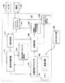
心臓事象を分類し治療の提供を制御するために使用される回路575は、装置400のハウジングに収納される。図5Aは、一実施形態に従うCRM回路575の機能ブロック図を示す。これらの機能ブロックを配置しうる構成として多くの可能な構成が存在することは当業者によって理解される。図5Aに描かれた例示的な装置は、実施可能な一つの機能構成である。他の構成も可能である。たとえば、さらに多くの機能ブロック、さらに少ない機能ブロック、あるいは異なる機能ブロックを用いて、本発明の手法を実現するのに適した装置を説明することができる。 Housed in the housing of the
CRM装置回路575は、典型的に、電気化学式電池(図示せず)によって給電される。メモリ545は、本発明の実施形態に従って心臓事象識別とともに治療提供などの他の操作を実施するために使用されるデータおよびプログラム命令を保存する。データおよびプログラム命令は、装置回路575と患者外部の装置555との間でテレメトリベースの通信回路550を経由して転送することができる。 The
回路575は、右心室、左心室、右心房および左心房のうちの少なくとも一つへのペーシングパルスおよび除細動ショックのうちの少なくとも一つの提供を制御できる治療制御プロセッサ565を含む。ペーシングパルス発生器530は、たとえば、徐脈性不整脈を処置するペーシングパルス、あるいは二心房および二心室のうちの少なくとも一つのペーシングを用いて対側心腔の収縮に同期するペーシングパルスを発生するように構成される。さらに、治療制御プロセッサ565の制御の下で、高エネルギーショックを発生させて頻脈性不整脈の発作を鎮めるために電気的除細動または除細動パルス発生器535を使用することができる。
ペーシングパルスおよび除細動ショックのうちの少なくとも一つは、心臓内、心臓表面、または心臓近傍の様々な位置に配置されて心臓に電気的に結合された複数の心臓電極505を経由して供給される。ある構成において、複数の電極は、単一心腔内に複数の感知および刺激部位のうちの少なくとも一つを提供することができる。電極505は、スイッチマトリクス回路525に結合され、スイッチマトリクス回路525は、電極505を感知回路510および治療パルス発生器530、535に選択的に結合するために使用される。 At least one of the pacing pulse and defibrillation shock is delivered via a plurality of
心臓の電気的活動は、患者の心臓の電極部位から、電極505および感知回路510を経由して感知することができる。他のタイプの信号、たとえば、心音信号、圧力信号、呼吸信号、およびその他のタイプの信号のうちの少なくとも一つは、感知回路510とともに様々なセンサ506を用いて感知することができる。センサ505、506および感知回路510を用いて得られる感知された信号は、信号処理回路515によって処理されて心臓事象検出に使用される心臓信号の特徴を強調する。信号処理回路515が適用される処理の種類は、識別の対象とされている心臓事象の種類に基づいていてもよい。たとえば、一状況において、感知された信号の心臓信号成分の形態は、心臓ペーシング応答の検出を容易にするために、第1の組の特徴を強化するように変更することができる。第2の状況において、感知された信号の心臓信号成分の形態は、頻脈性不整脈の検出を容易にするために、あるいは頻脈性不整脈の種類を識別するために第2の組の特徴を強調するように変更することができる。 Heart electrical activity can be sensed from the patient's heart electrode site via
感知された信号の心臓信号成分の形態の変更は、信号をフィルタ処理して一定の周波数成分を除去することによって実施することができる。たとえば、ハイパスフィルタ、ローパスフィルタ、またはバンドパスフィルタ処理を適用することができる。追加的または代替的に、心臓信号形態は、A/Dコンバータ分解能やサンプル周波数などのデータ収集パラメータを変えることによって変更することができる。電極505またはセンサ506および感知回路510を介して得られる信号は、感知された信号からノイズ成分を除去または低減するために、フィルタ処理することもできる。 Altering the form of the cardiac signal component of the sensed signal can be performed by filtering the signal to remove certain frequency components. For example, a high-pass filter, a low-pass filter, or a band-pass filter process can be applied. Additionally or alternatively, the cardiac signal morphology can be changed by changing data acquisition parameters such as A / D converter resolution and sample frequency. The signal obtained via
特徴の検出を強調するために修正された心臓信号は、心臓事象プロセッサ560によって分析される。この分析の間に、処理済みの信号に存在する心臓信号特徴は、様々な心臓事象を分類するために使用される。一状況において、心臓事象プロセッサ560は、処理済みの電気記録図(EGM)信号に存在する心臓信号特徴を使用して、ペーシングに対する心臓応答を分類する。たとえば、心臓応答検出ウィンドウ内の心臓信号ピークの有無によって、ペーシングパルスが捕捉、または他のペーシング応答(非捕捉、融合や偽融合、または内因性活性化を伴う非捕捉等)を生成したか否かを判断することができる。 The cardiac signal modified to enhance feature detection is analyzed by a
別の実施において、信号処理回路515によって修正された心臓信号は、心頻脈性不整脈発作のタイプを分類するために使用することができる。心臓発作時心拍の処理済み信号から抽出される特徴は、様々なタイプの頻脈性不整脈を代表するテンプレート特徴と比較することができる。発作時心拍の処理済み信号特徴の振幅、タイミング、およびその他の特性のうちの少なくとも一つは、対応するテンプレート特徴と比較される。発作心拍特徴とテンプレート特徴とが酷似している場合、心臓事象プロセッサ560は心臓発作をテンプレートによって表わされる頻脈性不整脈のタイプであると識別する。 In another implementation, the cardiac signal modified by the
一部の実施において、信号処理回路515のパラメータは、人口データに基づいて選択することができる。たとえば、一定のフィルタが総患者人口全体にわたる信号特徴の所望形態を提供する場合、信号を処理するために一定のフィルタ構成を選定することができる。一つの捕捉アプリケーションにおいて、約3Hzのハイパスコーナー周波数と約100Hzのローパスコーナー周波数とを有するフィルタは、所望の振幅およびタイミングで発生する負および正の信号ピークを生成する。心臓ペーシング応答の決定には、検出ウィンドウ内の正および負のうちの少なくとも一つのピークの有無の感知が伴う可能性がある。多くの患者で、これらの信号処理パラメータにより、心臓信号ピークの位置およびタイミングに基づいて正確な心臓ペーシング応答を決定する心臓信号が提供される。 In some implementations, the parameters of the
図5Bに示されるように、ある実施形態において、信号処理回路515は、信号処理ユニット581〜584のバンクとして実現することができ、この場合、各信号処理ユニット581〜584は独自のパラメータ集合を有する。たとえば、各信号処理ユニット581〜584では、特定タイプの心臓事象に対して特徴の検出を強調するために選択されたパラメータを使用することができる。感知回路510(図5A)からの心臓信号は、信号処理ユニット581〜584の各々によって処理することができる。信号処理ユニット581〜584の出力は、心臓事象の有無を検出するために心臓事象プロセッサ560によって分析される。 As shown in FIG. 5B, in one embodiment, the
たとえば、図5Bに示されるように、第1の信号処理ユニット581は、正常洞調律(NSR)に対する特徴の検出を強調するように構成することができる。第2の信号処理ユニット582は、上室性頻脈性不整脈(SVT)に対する特徴の検出を強調するように構成することができる。第3の信号処理ユニット583は、第1のタイプの心室頻脈(VTA)に対する特徴の検出を強調するように構成することができる。第4の信号処理ユニット584は、第2のタイプの心室頻脈(VTB)に対する特徴の検出を強調するように構成することができる。信号処理ユニット582〜584の出力は、場合によってはNSR591、SVT592、VTA593、およびVTB594を識別する回路を含む心臓事象プロセッサ560に加えられる。一実施において、心臓事象プロセッサ560は、信号処理ユニット581〜584によって処理された信号をNSR、SVT、VTA、およびVTBを表わすテンプレートと比較するために、回路591〜594を含んでもよい。信号事象の識別は、処理済みの心臓信号とテンプレートとの間の相関度に基づいていてもよい。 For example, as shown in FIG. 5B, the first
病状、患者の病態生理、センサの特性、およびリードの植込み特性のうちの少なくとも一つによっては、上記の均一なパラメータ設定値が一部の患者に対して準最適な特徴検出をもたらす場合がある。一部の実施形態において、信号処理パラメータの設定値は、外部のデバイスプログラマ、または他の遠隔装置管理システムによってプログラム可能である場合がある。たとえば、一状況において、医師などの医療提供者は、信号処理に関するパラメータを選択し、選択されたパラメータを用いて処理された心臓信号の変化を観察することができる。医師は、心臓信号の観察を通じて、特徴の検出を強調するために選択されたパラメータが心臓信号形態に所望の改善をもたらすかどうかを判断することができる。別の状況において、医師は、修正されたパラメータが所望の効果、たとえば、頻脈性不整脈発作のさらに正確な捕捉検出および識別のうちの少なくとも一つをもたらすかどうかを判断することができる。 Depending on the pathology, patient pathophysiology, sensor characteristics, and lead implantation characteristics, the above uniform parameter settings may result in sub-optimal feature detection for some patients. . In some embodiments, signal processing parameter settings may be programmable by an external device programmer or other remote device management system. For example, in one situation, a health care provider, such as a physician, can select parameters for signal processing and observe changes in the cardiac signal processed using the selected parameters. The physician can determine, through observation of the cardiac signal, whether the parameters selected to enhance feature detection provide the desired improvement in cardiac signal morphology. In another situation, the physician can determine whether the modified parameter provides at least one of the desired effects, eg, more accurate capture detection and identification of tachyarrhythmia attacks.
一部の実施形態において、個人に合わせたパラメータ設定値の選択は、装置によって自動的に行なうことができる。たとえば、装置は、パラメータ設定値が自動的に増分変化され、パラメータの各々を用いて生成される信号が分析される過程を実現する。この過程は、心臓信号における一つ以上の望ましくない特徴が抑制されて最後に望ましい特徴が際立つようになるまで、すなわち、最適なパラメータ設定値が決定されるまで続く可能性がある。たとえば、一実施において、装置は、信号における望ましくない特徴を識別し、その後、有効な信号処理パラメータ設定を自動的に行い、各設定値が望ましくない特徴を除去または十分に抑制しているかどうか、あるいはその程度を判断することができる。望ましくない信号特徴を心臓信号から排除することが可能でない場合、望ましくない特徴を最大限に抑制する最適なパラメータ設定値が選択される。他の実施において、望ましい特徴は、信号処理パラメータの自動修正を採用することによって強調することができる。たとえば、装置は、有効な信号処理パラメータ設定を行い、鋭い信号ピークを生じる最適なパラメータ設定値を決定することができる。 In some embodiments, personalized parameter setting values can be automatically selected by the device. For example, the device implements a process in which parameter settings are automatically incremented and the signal generated using each of the parameters is analyzed. This process may continue until one or more undesired features in the cardiac signal are suppressed and finally the desired features become noticeable, i.e., the optimal parameter settings are determined. For example, in one implementation, the apparatus identifies undesired features in the signal, then automatically performs valid signal processing parameter settings, and whether each setting removes or sufficiently suppresses undesired features; Alternatively, the degree can be determined. If it is not possible to eliminate unwanted signal features from the cardiac signal, the optimal parameter settings that will minimize the unwanted features are selected. In other implementations, desirable features can be emphasized by employing automatic modification of signal processing parameters. For example, the device can make effective signal processing parameter settings and determine optimal parameter settings that produce sharp signal peaks.
望ましくない特徴を抑制し、望ましい特徴を強調し、かつ信号を処理するための最適なパラメータ設定値を決定することのうちの少なくとも一つを行う方法は、ファームウェア、ソフトウェア、またはファームウェアとソフトウェアの両方の組合せで実施することができる。自動化パラメータ選択法は、要求に応じて、周期的および心臓事象識別の劣化が検出されたときのうちの少なくとも一つの時期に実施することができる。たとえば、捕捉検出が実現不可能であるか一時的に停止する場合、捕捉検出に使用される信号処理パラメータ設定値を試験して再調整することができる。 A method of suppressing at least one of undesired features, highlighting the desired features, and determining at least one of optimal parameter settings for processing the signal is firmware, software, or both firmware and software It can be implemented in combination. The automated parameter selection method can be performed on demand, at least one time period when periodic and cardiac event identification degradation is detected. For example, if capture detection is not feasible or temporarily stops, the signal processing parameter settings used for capture detection can be tested and readjusted.
図6のフローグラフは、本発明の実施形態に従って特徴を強調するための信号処理パラメータを自動的に決定する方法を示す。信号処理回路のパラメータ設定値が初期化される(610)。心臓信号が感知され初期パラメータ設定値を用いて処理される(620)。処理された心臓信号は、心臓事象の識別に干渉する可能性のある望ましくない特徴の有無について分析される(630)。試験対象となる別の信号処理パラメータ設定値があれば(640)、信号処理回路のパラメータが新たな設定値に修正される(660)。心臓信号が感知されて新たな設定値を用いて処理される(620)。処理された信号は、望ましくない特徴の有無について再び分析される(630)。この過程は、すべてのパラメータ設定値が試験されるまで続く。特徴を強調するための最適パラメータ設定値は、すべてのパラメータ設定値が試験された後で選択される(650)。 The flow graph of FIG. 6 illustrates a method for automatically determining signal processing parameters for enhancing features in accordance with an embodiment of the present invention. The parameter setting value of the signal processing circuit is initialized (610). A cardiac signal is sensed and processed using the initial parameter settings (620). The processed cardiac signal is analyzed for the presence of undesirable features that may interfere with the identification of cardiac events (630). If there is another signal processing parameter setting value to be tested (640), the parameter of the signal processing circuit is modified to a new setting value (660). A cardiac signal is sensed and processed using the new setpoint (620). The processed signal is analyzed again (630) for the presence of undesirable features. This process continues until all parameter settings have been tested. Optimal parameter settings for highlighting features are selected (650) after all parameter settings have been tested.
心臓信号における望ましくない特徴の有無は、様々な手法を用いて判断することができる。本明細書では複数の例示的な手法が説明されるが、望ましくない特徴の有無を検出する手法、あるいは望ましい特徴と望ましくない特徴の比較強度を分析する手法はいずれも採用することができる。 The presence or absence of undesirable features in the cardiac signal can be determined using various techniques. Although a plurality of exemplary methods are described in this specification, any of a method for detecting the presence or absence of an undesired feature or a method for analyzing a comparison strength between a desired feature and an undesired feature can be adopted.
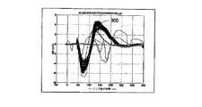
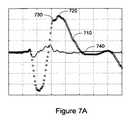
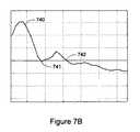
望ましくない特徴の有無を判断する勾配解析を用いる手法は、捕捉検出に使用される心臓信号と関連付けて説明される。図7Aは、2つの正のピーク720、730を表わす形態を有する心臓信号710を示す。前述の通り、捕捉検出は、所定の振幅およびタイミングの範囲を有する検出ウィンドウ内に現れる信号ピークに依存する場合がある。ダブルピークが存在すると、たとえば、一つのピークがウィンドウ内にあり、一つのピークがウィンドウ外にあるとき、捕捉検出が不確実になることがある。したがって、適切な信号処理によってダブルピークを排除することが望ましい。 Techniques using gradient analysis to determine the presence or absence of undesirable features are described in connection with cardiac signals used for capture detection. FIG. 7A shows a
一実施形態に従って、心臓信号における複数ピークの有無は勾配解析を用いて検出することができる。この過程において、心臓信号710の勾配740が決定される。心臓信号の勾配740は、図7Aおよび7Bにグラフを使って示される。心臓信号710のピークは、ゼロ交差の近くの勾配で示される。心臓信号710の主ピーク720は、ゼロ交差742の近くの勾配740で示される。主ピーク720の近くにある別のピーク730は、ゼロ交差741の近くの勾配740で示される。 According to one embodiment, the presence or absence of multiple peaks in the cardiac signal can be detected using gradient analysis. In this process, the
図7Aおよび7Bに示されるように、主ピークゼロ交差の位置に近い位置で心臓信号勾配740において一つ以上の新たなゼロ公差が検出される場合、この特定心臓信号形態に対する信号処理パラメータは最適でない。信号処理パラメータは、第2のピークの存在を排除または抑制するように変更することができる。 As shown in FIGS. 7A and 7B, if one or more new zero tolerances are detected in the
図7Cおよび7Dは、ダブルピークを抑制するように処理された後の心臓信号750を示す。処理済みの心臓信号750は、ゼロ交差771の近くの心臓信号勾配770で示される単一ピーク760を表わす。 Figures 7C and 7D show the
図7Aに示される複数ピークのような心臓信号の望ましくない特徴を検出するもう一つの方法では、曲率ベースの解析を採用する必要がある。曲率解析によって、心臓信号の特異点が、ピーク検出とともに心臓信号の曲率に基づいて決定される。主ピークの近くに振幅と位置とを有する第2のピークを示す新たな特異点がある場合、信号処理パラメータ設定値を修正して第2のピークを排除することができる。たとえば、ピークおよび変曲点のうちの少なくとも一つを含む心臓信号特徴を検出するための曲率解析の採用については、共同所有された米国特許第6,950,702号明細書にさらに記載されており、この特許は本明細書に参考として組み入れられる。 Another method of detecting undesired features of the heart signal, such as the multiple peaks shown in FIG. 7A, requires the use of curvature-based analysis. By curvature analysis, a singular point of the heart signal is determined based on the curvature of the heart signal along with peak detection. If there is a new singular point showing a second peak with amplitude and position near the main peak, the signal processing parameter set value can be modified to eliminate the second peak. For example, the use of curvature analysis to detect cardiac signal features including at least one of a peak and an inflection point is further described in co-owned US Pat. No. 6,950,702. And this patent is incorporated herein by reference.
本発明の実施形態に従って特徴の検出を強調するための心臓信号処理パラメータの修正は、頻脈性不整脈事象の識別を改善するように適用することができる。形態学に基づく不整脈検出において、心臓信号の特徴点が抽出され、テンプレート特徴との相関が計算される。相関係数が所定の閾値よりも高い場合、心拍はテンプレートによって表わされる心拍タイプに分類される。 Modification of cardiac signal processing parameters to enhance feature detection according to embodiments of the invention can be applied to improve identification of tachyarrhythmia events. In arrhythmia detection based on morphology, feature points of the heart signal are extracted and correlations with template features are calculated. If the correlation coefficient is higher than a predetermined threshold, the heartbeat is classified into the heartbeat type represented by the template.
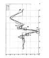
一実施において、検出された心拍信号は、上室性調律(SVR)を代表するテンプレートと比較される。心拍信号がSVRテンプレートと相関がある場合、心拍はSVRに分類されて治療は見合わされる。心拍信号がSVRテンプレートと相関がない場合、心拍は心室頻脈に分類されて治療が提供される可能性がある。この方法によると、特徴点1〜8は、図8に示されるように、心臓信号810から抽出される。8つの特徴点の採用は、2つの変曲点のみ(図8における特徴2と特徴4)がSVR心拍に対応するピーク特徴3の付近の領域820に存在するとの前提に基づいている。領域820にさらなる変曲点がある場合、特徴2、3、および4は、これらの特徴点を決定する際の変動に起因してテンプレートの形成中に正しく識別されないかもしれない。さらに、調律分析は、領域830内の曲率に有意な変動がないとの前提に基づいている。この前提が正しくなければ、形態の局所的変化が各心拍間の相関中およびテンプレートの形成中に特徴2、3、4、7、および8の決定に変動をもたらす可能性がある。形態の局所的変化がもたらす特徴点変動は、心調律のタイプを正確に分類する能力に影響を与える可能性がある。 In one implementation, the detected heartbeat signal is compared to a template representative of supraventricular rhythm (SVR). If the heart rate signal is correlated with the SVR template, the heart rate is classified as SVR and treatment is paid off. If the heartbeat signal is uncorrelated with the SVR template, the heartbeat may be classified as ventricular tachycardia to provide treatment. According to this method, feature points 1-8 are extracted from the
本発明の方法に従って、領域820および830に現れる望ましくない形態や曲率を排除する信号処理パラメータを決定することができる。前述の勾配または曲率ベースの方法は、望ましくない変曲点を検出するために採用することができる。たとえば、変曲点は、勾配がゼロの場合の点として勾配法を用いて検出することができる。 In accordance with the method of the present invention, signal processing parameters that eliminate undesirable features and curvatures appearing in
図9は、ウィンドウ領域内での曲率の著しい変化および複数の変曲点のうちの少なくとも一つを検出しやすくする働きをするQRS複合特徴点位置(特徴2、3、4、7、および8)を囲むように描かれたウィンドウを示す。その結果、信号処理パラメータは、ウィンドウ領域における望ましくない特徴を抑制または排除するように選択することができる。信号処理パラメータは、保存された発作の心拍とテンプレートの心拍との間に最良の相関が生じるように最適化することができる。調整が行なわれた後で信号処理パラメータが著しく異なる場合、新たなテンプレートの更新を開始することができ、その結果得られたテンプレートをメモリに保存された過去のテンプレートと比較することができる。両テンプレートが形態学的に異なる場合、新たなテンプレートをメモリに保存して古いテンプレートと置き換えることができる。 FIG. 9 shows QRS composite feature point positions (features 2, 3, 4, 7, and 8 that serve to facilitate detection of a significant change in curvature and at least one of a plurality of inflection points in the window region. ) Shows a window drawn around. As a result, signal processing parameters can be selected to suppress or eliminate unwanted features in the window region. The signal processing parameters can be optimized to produce the best correlation between the stored seizure heart rate and the template heart rate. If the signal processing parameters are significantly different after the adjustment has been made, a new template update can be initiated and the resulting template can be compared to a past template stored in memory. If both templates are morphologically different, a new template can be stored in memory to replace the old template.
信号のエネルギーまたは電力を使用するなどして、心臓信号成分における望ましくない特徴を検出し、望ましい特徴を強調する方法はほかにもある。たとえば、捕捉検出の例では、陽性波と陰性波と統合し、最適パラメータとして最小積分を生成する信号処理パラメータを選定することが可能であるかもしれない。 There are other ways to detect unwanted features in the cardiac signal component and emphasize the desired features, such as by using signal energy or power. For example, in the capture detection example, it may be possible to select a signal processing parameter that integrates positive and negative waves and produces a minimum integral as the optimal parameter.
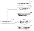
信号処理パラメータの決定は、患者人口データに基づいて実施することも特定患者に合わせて個々に実施することもできる。先述のように、信号処理パラメータは、自動的に決定することも手動で決定することもできる。一方法において、信号処理パラメータは、テンプレートの作成中および更新中のうちの少なくとも一つにおいて決定することができる。別の方法において、信号処理パラメータは、患者の保存された発作データに基づいて決定することができる。別の方法において、信号処理パラメータを医師が選択して装置にアップロードすることができる。さらに別の方法において、医師は、ペーシングを実行またはプロトコルを使用して頻発性不整脈をシミュレートすることができ、装置が頻発性不整脈のシミュレーションの間に信号処理パラメータを調整して頻発性不整脈の検出を強調することができる。 The determination of signal processing parameters can be performed based on patient population data or individually for a particular patient. As mentioned above, the signal processing parameters can be determined automatically or manually. In one method, the signal processing parameters can be determined during at least one of creating and updating the template. In another method, the signal processing parameters can be determined based on the patient's stored seizure data. In another method, signal processing parameters can be selected by the physician and uploaded to the device. In yet another method, a physician can perform pacing or use a protocol to simulate frequent arrhythmias, and the device can adjust signal processing parameters during frequent arrhythmia simulations to detect frequent arrhythmias. Detection can be emphasized.
前述の実施形態に対しては、本発明の範囲から逸脱することなく様々な修正および追加を行なうことができる。それゆえ、本発明の範囲は、前述の特定の実施形態によって限定されるべきでなく、以下に記述する特許請求の範囲およびその等効物によってのみ規定されるべきである。 Various modifications and additions may be made to the above-described embodiments without departing from the scope of the present invention. Therefore, the scope of the present invention should not be limited by the specific embodiments described above, but should be defined only by the claims set forth below and their equivalents.
Claims (9)
Translated fromJapanese前記一つ以上の電極における心臓信号成分およびノイズ信号成分を含む信号を前記感知回路により感知することであって、感知された前記心臓信号成分は、信号検出ウィンドウ内に含まれる第1のピークと、該信号検出ウィンドウから外れた第2のピークとを含む、感知すること、
前記信号処理回路を用いてフィルタリングにより前記感知された信号を処理して、前記感知された信号の前記心臓信号成分の形態を選択的に変更することであって、前記心臓信号成分の変更された形態は、前記心臓信号成分の一つ以上の特徴の検出を強調したものであり、処理後、前記心臓信号成分の形態は、前記心臓成分信号の前記第2のピークが前記信号検出ウィンドウ内で感知されることがないように変更される、前記信号を処理すること、
前記心臓信号成分の変更された形態を用いて前記一つ以上の特徴を検出すること、
前記心臓事象処理回路が検出された前記一つ以上の特徴を用いて、前記心臓事象を分類すること
を備える方法。A method of classifying a cardiac event using a CRM device that includes one or more electrodes, a sensing circuit, a signal processing circuit, and a cardiac event processing circuit, comprising:
Sensing a signal including a cardiac signal component and a noise signal component at the one or more electrodes by the sensing circuit, wherein the sensedcardiac signal component includes a first peak included in a signal detection window; Sensing a second peak outside the signal detection window ;
Processing the sensed signal by filtering using the signal processing circuit to selectively change a form of the cardiac signal component of the sensed signal, wherein the cardiac signal component is changed. The form emphasizes the detection of one or more features of the cardiac signal component, andafter processing, the form of the cardiac signal component is such that the second peak of the cardiac component signal is within the signal detection window. Processing the signal, changed so as not to be sensed ;
Detecting the one or more featuresusing a modified form of the cardiac signal component ;
How comprising that said cardiac event processing circuitis detected using one or moreof the feature, classifying the cardiac event.
心臓信号成分およびノイズ成分を含む信号を感知するように構成された感知回路であって、感知された前記心臓信号成分は、信号検出ウィンドウ内に含まれる第1のピークと、該信号検出ウィンドウから外れた第2のピークとを含む、前記感知回路と、
フィルタリングにより前記感知された心臓信号を処理して、前記感知された信号の前記感知された心臓信号成分の形態を変更するように構成されて、処理後、変更された前記心臓成分信号の前記第2のピークが前記信号検出ウィンドウ内で感知されることがなく、前記変更された心臓信号成分の一つ以上の特徴の検出を強調するようにする信号処理回路と、
変更された前記心臓信号成分の前記一つ以上の特徴を検出するように構成された特徴検出器と、
変更された前記心臓信号成分の前記一つ以上の検出された特徴を用いて心臓事象を分類するように構成された心臓事象プロセッサと、
を備える医療システム。A medical system,
A sensing circuit configured to sense a signal including a cardiac signal component and a noise component,wherein the sensed cardiac signalcomponent isderived from a first peak included inthe signal detection windowand the signal detection window. The sensing circuit including asecond peak that is off ;
The sensed cardiac signal is processed by filtering to change the shape of the sensed cardiac signal component of the sensed signal, andafter processing, the first of the altered cardiac component signal. A signal processing circuit that enhances the detection of one or more features of the altered cardiac signal component, whereinno two peaks are sensed within the signal detection window ;
A feature detector configured to detect the one or more features of thealtered cardiac signal component;
A cardiac event processor configured to classify cardiac events using the one or more detected features of themodified cardiac signal component ;
A medical system comprising:
Applications Claiming Priority (3)
| Application Number | Priority Date | Filing Date | Title |
|---|---|---|---|
| US11/717,482 | 2007-03-13 | ||
| US11/717,482US20080228093A1 (en) | 2007-03-13 | 2007-03-13 | Systems and methods for enhancing cardiac signal features used in morphology discrimination |
| PCT/US2008/001986WO2008112060A1 (en) | 2007-03-13 | 2008-02-14 | Systems and methods for enhancing cardiac signal features used in morphology discrimination |
Publications (2)
| Publication Number | Publication Date |
|---|---|
| JP2010516430A JP2010516430A (en) | 2010-05-20 |
| JP5386372B2true JP5386372B2 (en) | 2014-01-15 |
Family
ID=39537508
Family Applications (1)
| Application Number | Title | Priority Date | Filing Date |
|---|---|---|---|
| JP2009548345AExpired - Fee RelatedJP5386372B2 (en) | 2007-03-13 | 2008-02-14 | System and method for enhancing features of cardiac signals used for morphological identification |
Country Status (5)
| Country | Link |
|---|---|
| US (1) | US20080228093A1 (en) |
| EP (1) | EP2136703B1 (en) |
| JP (1) | JP5386372B2 (en) |
| AT (1) | ATE550985T1 (en) |
| WO (1) | WO2008112060A1 (en) |
Families Citing this family (23)
| Publication number | Priority date | Publication date | Assignee | Title |
|---|---|---|---|---|
| WO2009092055A1 (en) | 2008-01-18 | 2009-07-23 | Cameron Health, Inc. | Data manipulation following delivery of a cardiac stimulus in an implantable cardiac stimulus device |
| ES2605653T3 (en) | 2008-03-07 | 2017-03-15 | Cameron Health, Inc. | Devices to accurately classify cardiac activity |
| CA2717442C (en) | 2008-03-07 | 2017-11-07 | Cameron Health, Inc. | Accurate cardiac event detection in an implantable cardiac stimulus device |
| EP2446926B1 (en) | 2008-05-07 | 2013-06-26 | Cameron Health, Inc. | Devices for accurately classifying cardiac activity |
| WO2010068933A1 (en) | 2008-12-12 | 2010-06-17 | Cameron Health, Inc. | Electrode spacing in a subcutaneous implantable cardiac stimulus device |
| AU2010210840B2 (en)* | 2009-02-06 | 2013-03-07 | Cardiac Pacemakers, Inc. | Cross-channel noise detector in implantable devices |
| CA2766866A1 (en) | 2009-06-29 | 2011-01-20 | Cameron Health, Inc. | Adaptive confirmation of treatable arrhythmia in implantable cardiac stimulus devices |
| US8744555B2 (en) | 2009-10-27 | 2014-06-03 | Cameron Health, Inc. | Adaptive waveform appraisal in an implantable cardiac system |
| US8265737B2 (en) | 2009-10-27 | 2012-09-11 | Cameron Health, Inc. | Methods and devices for identifying overdetection of cardiac signals |
| US20110152698A1 (en)* | 2009-12-23 | 2011-06-23 | Greenhut Saul E | Method and apparatus for blood pressure waveform baseline estimation and removal |
| WO2011088043A1 (en)* | 2010-01-12 | 2011-07-21 | Cardiac Pacemakers, Inc. | Use of significant point methodology to prevent inappropriate therapy |
| US8548573B2 (en) | 2010-01-18 | 2013-10-01 | Cameron Health, Inc. | Dynamically filtered beat detection in an implantable cardiac device |
| US8744556B2 (en) | 2011-02-04 | 2014-06-03 | Cardiac Pacemakers, Inc. | Noise detection in implantable medical devices |
| US9020596B2 (en) | 2011-07-15 | 2015-04-28 | Cardiac Pacemakers, Inc. | Management of fusion beat detection during capture threshold determination |
| US8751499B1 (en) | 2013-01-22 | 2014-06-10 | Splunk Inc. | Variable representative sampling under resource constraints |
| US20140114200A1 (en)* | 2012-10-19 | 2014-04-24 | Hill-Rom Services, Inc. | Composite manual and automated fetal analysis systems and methods |
| CN104955387B (en)* | 2012-11-29 | 2018-03-30 | 心脏起搏器股份公司 | The method and system differentiated for arrhythmia cordis |
| WO2014164530A1 (en) | 2013-03-11 | 2014-10-09 | Cameron Health, Inc. | Methods and devices implementing dual criteria for arrhythmia detection |
| CN103278702B (en)* | 2013-06-19 | 2016-03-23 | 深圳市理邦精密仪器股份有限公司 | Extract intelligent detection unit, the method and system of PACE ripple |
| US9554714B2 (en) | 2014-08-14 | 2017-01-31 | Cameron Health Inc. | Use of detection profiles in an implantable medical device |
| JP2016140317A (en)* | 2015-02-03 | 2016-08-08 | ソニー株式会社 | Information processor, information processing method, program, and observation system |
| US10433749B2 (en)* | 2016-08-10 | 2019-10-08 | Biosense Webster (Israel) Ltd. | Identifying ECG signals having the same morphology |
| US12076574B2 (en) | 2020-10-08 | 2024-09-03 | Cardiac Pacemakers, Inc. | Cardiac beat classification to avoid delivering shock during ventricular repolarization |
Family Cites Families (101)
| Publication number | Priority date | Publication date | Assignee | Title |
|---|---|---|---|---|
| US4023564A (en)* | 1976-01-26 | 1977-05-17 | Spacelabs, Inc. | Arrhythmia detector |
| US4562841A (en)* | 1982-08-05 | 1986-01-07 | Cardiac Pacemakers, Inc. | Programmable multi-mode cardiac pacemaker |
| US4648407A (en)* | 1985-07-08 | 1987-03-10 | Respitrace Corporation | Method for detecting and differentiating central and obstructive apneas in newborns |
| US4827935A (en)* | 1986-04-24 | 1989-05-09 | Purdue Research Foundation | Demand electroventilator |
| US6375621B1 (en)* | 1987-03-06 | 2002-04-23 | Ocean Laboratories, Inc. | Passive apnea monitor |
| US4928688A (en)* | 1989-01-23 | 1990-05-29 | Mieczyslaw Mirowski | Method and apparatus for treating hemodynamic disfunction |
| US5105354A (en)* | 1989-01-23 | 1992-04-14 | Nippon Kayaku Kabushiki Kaisha | Method and apparatus for correlating respiration and heartbeat variability |
| JP2794196B2 (en)* | 1989-06-20 | 1998-09-03 | チェスト株式会社 | Apnea prevention stimulator |
| JPH0341926A (en)* | 1989-07-07 | 1991-02-22 | Matsushita Electric Works Ltd | Detector for change in sleeping state and sleeping state controller |
| US5000189A (en)* | 1989-11-15 | 1991-03-19 | Regents Of The University Of Michigan | Method and system for monitoring electrocardiographic signals and detecting a pathological cardiac arrhythmia such as ventricular tachycardia |
| US5284136A (en)* | 1990-04-04 | 1994-02-08 | Cardiac Pacemakers, Inc. | Dual indifferent electrode pacemaker |
| US5187657A (en)* | 1990-04-05 | 1993-02-16 | Hewlett-Packard Company | Cardiac analyzer with rem sleep detection |
| US5203348A (en)* | 1990-06-06 | 1993-04-20 | Cardiac Pacemakers, Inc. | Subcutaneous defibrillation electrodes |
| US5411529A (en)* | 1990-08-10 | 1995-05-02 | Medtronic, Inc. | Waveform discriminator for cardiac stimulation devices |
| US5222493A (en)* | 1990-10-01 | 1993-06-29 | Siemens Pacesetter, Inc. | Verification of capture using an indifferent electrode mounted on the pacemaker connector top |
| US5184615A (en)* | 1991-03-08 | 1993-02-09 | Telectronics Pacing Systems, Inc. | Apparatus and method for detecting abnormal cardiac rhythms using evoked potential measurements in an arrhythmia control system |
| US5217021A (en)* | 1991-07-30 | 1993-06-08 | Telectronics Pacing Systems, Inc. | Detection of cardiac arrhythmias using correlation of a cardiac electrical signals and temporal data compression |
| US5313953A (en)* | 1992-01-14 | 1994-05-24 | Incontrol, Inc. | Implantable cardiac patient monitor |
| US5301677A (en)* | 1992-02-06 | 1994-04-12 | Cardiac Pacemakers, Inc. | Arrhythmia detector using delta modulated turning point morphology of the ECG wave |
| EP0570895B1 (en)* | 1992-05-18 | 2003-12-03 | Cardiac Pacemakers, Inc. | System for event processing in biological applications |
| US5324310A (en)* | 1992-07-01 | 1994-06-28 | Medtronic, Inc. | Cardiac pacemaker with auto-capture function |
| DE69323374T2 (en)* | 1992-09-30 | 1999-06-10 | Cardiac Pacemakers, Inc., Saint Paul, Minn. | Foldable cushion electrode for cardiac defibrillation with an area without conductors, which serves as a hinge |
| US5517983A (en)* | 1992-12-09 | 1996-05-21 | Puritan Bennett Corporation | Compliance meter for respiratory therapy |
| US5397342A (en)* | 1993-06-07 | 1995-03-14 | Cardiac Pacemakers, Inc. | Resilient structurally coupled and electrically independent electrodes |
| US5411031A (en)* | 1993-11-24 | 1995-05-02 | Incontrol, Inc. | Implantable cardiac patient monitor |
| US5738102A (en)* | 1994-03-31 | 1998-04-14 | Lemelson; Jerome H. | Patient monitoring system |
| US7027868B2 (en)* | 2001-10-30 | 2006-04-11 | Medtronic, Inc. | Capture management improvements |
| US5485851A (en)* | 1994-09-21 | 1996-01-23 | Medtronic, Inc. | Method and apparatus for arousal detection |
| US5626620A (en)* | 1995-02-21 | 1997-05-06 | Medtronic, Inc. | Dual chamber pacing system and method with continual adjustment of the AV escape interval so as to maintain optimized ventricular pacing for treating cardiomyopathy |
| US5545186A (en)* | 1995-03-30 | 1996-08-13 | Medtronic, Inc. | Prioritized rule based method and apparatus for diagnosis and treatment of arrhythmias |
| AUPN236595A0 (en)* | 1995-04-11 | 1995-05-11 | Rescare Limited | Monitoring of apneic arousals |
| JPH09173310A (en)* | 1995-11-29 | 1997-07-08 | Hewlett Packard Co <Hp> | Method and device for classifying heartbeats from ecg waveform |
| DE69718523T2 (en)* | 1996-05-14 | 2003-11-20 | Medtronic, Inc. | Priority device for cardiac arrhythmia diagnosis and treatment |
| US5857977A (en)* | 1996-08-08 | 1999-01-12 | The Regents Of The University Of Michigan | Method and apparatus for separation of ventricular tachycardia from ventricular fibrillation for implantable cardioverter defibrillators |
| US6295470B1 (en)* | 1996-08-19 | 2001-09-25 | The Mower Family Chf Treatment Irrevocable Trust | Antitachycardial pacing |
| US5860918A (en)* | 1996-11-22 | 1999-01-19 | Hewlett-Packard Company | Representation of a review of a patent's physiological parameters |
| SE9604320D0 (en)* | 1996-11-25 | 1996-11-25 | Pacesetter Ab | Medical device |
| US5876353A (en)* | 1997-01-31 | 1999-03-02 | Medtronic, Inc. | Impedance monitor for discerning edema through evaluation of respiratory rate |
| SE9700396D0 (en)* | 1997-02-05 | 1997-02-05 | Pacesetter Ab | Heart stimulating device |
| US5861011A (en)* | 1997-02-14 | 1999-01-19 | Vitatron Medical, B.V. | Pacemaker with automatic lower rate limit drop |
| IL122875A0 (en)* | 1998-01-08 | 1998-08-16 | S L P Ltd | An integrated sleep apnea screening system |
| US6144880A (en)* | 1998-05-08 | 2000-11-07 | Cardiac Pacemakers, Inc. | Cardiac pacing using adjustable atrio-ventricular delays |
| US6045513A (en)* | 1998-05-13 | 2000-04-04 | Medtronic, Inc. | Implantable medical device for tracking patient functional status |
| US6026320A (en)* | 1998-06-08 | 2000-02-15 | Cardiac Pacemakers, Inc. | Heart rate variability as an indicator of exercise capacity |
| JP2000033922A (en)* | 1998-07-21 | 2000-02-02 | Kootex:Kk | Long-sized engaging piece group |
| US6055454A (en)* | 1998-07-27 | 2000-04-25 | Cardiac Pacemakers, Inc. | Cardiac pacemaker with automatic response optimization of a physiologic sensor based on a second sensor |
| US6345201B1 (en)* | 1998-07-29 | 2002-02-05 | Pacesetter, Inc. | System and method for ventricular capture using far-field evoked response |
| US6044298A (en)* | 1998-10-13 | 2000-03-28 | Cardiac Pacemakers, Inc. | Optimization of pacing parameters based on measurement of integrated acoustic noise |
| US6169921B1 (en)* | 1998-12-08 | 2001-01-02 | Cardiac Pacemakers, Inc. | Autocapture determination for an implantable cardioverter defibrillator |
| US6038474A (en)* | 1999-03-02 | 2000-03-14 | Cardiac Pacemakers, Inc. | Pseudo-fusion management during automatic capture verification |
| US6324421B1 (en)* | 1999-03-29 | 2001-11-27 | Medtronic, Inc. | Axis shift analysis of electrocardiogram signal parameters especially applicable for multivector analysis by implantable medical devices, and use of same |
| US6175766B1 (en)* | 1999-03-30 | 2001-01-16 | Pacesetter, Inc. | Cardiac pacemaker autothreshold arrangement and method with reliable capture |
| US6190326B1 (en)* | 1999-04-23 | 2001-02-20 | Medtrac Technologies, Inc. | Method and apparatus for obtaining patient respiratory data |
| US6169919B1 (en)* | 1999-05-06 | 2001-01-02 | Beth Israel Deaconess Medical Center, Inc. | System and method for quantifying alternation in an electrocardiogram signal |
| US6192275B1 (en)* | 1999-05-11 | 2001-02-20 | Cardiac Pacemakers, Inc. | Adaptive evoked response sensing for automatic capture verification |
| US6226551B1 (en)* | 1999-05-11 | 2001-05-01 | Cardiac Pacemakers, Inc. | Wide-band evoked response sensing for capture verification |
| DE60029776T2 (en)* | 1999-05-12 | 2007-08-02 | Medtronic, Inc., Minneapolis | MONITORING DEVICE USING WAVELET TRANSFORMATIONS FOR CARDIAC RATIO ANALYSIS |
| US6351669B1 (en)* | 1999-05-21 | 2002-02-26 | Cardiac Pacemakers, Inc. | Cardiac rhythm management system promoting atrial pacing |
| US6312378B1 (en)* | 1999-06-03 | 2001-11-06 | Cardiac Intelligence Corporation | System and method for automated collection and analysis of patient information retrieved from an implantable medical device for remote patient care |
| US6221011B1 (en)* | 1999-07-26 | 2001-04-24 | Cardiac Intelligence Corporation | System and method for determining a reference baseline of individual patient status for use in an automated collection and analysis patient care system |
| US6368284B1 (en)* | 1999-11-16 | 2002-04-09 | Cardiac Intelligence Corporation | Automated collection and analysis patient care system and method for diagnosing and monitoring myocardial ischemia and outcomes thereof |
| US6336903B1 (en)* | 1999-11-16 | 2002-01-08 | Cardiac Intelligence Corp. | Automated collection and analysis patient care system and method for diagnosing and monitoring congestive heart failure and outcomes thereof |
| US6505071B1 (en)* | 1999-12-15 | 2003-01-07 | Cardiac Pacemakers, Inc. | Cardiac management device with capability of noise detection in automatic capture verification |
| US6371922B1 (en)* | 2000-04-07 | 2002-04-16 | Cardiac Pacemakers, Inc. | Method for measuring baroreflex sensitivity and therapy optimization in heart failure patients |
| WO2001076459A2 (en)* | 2000-04-10 | 2001-10-18 | The Research Foundation Of State University Of New York | Method for detecting cheyne-stokes respiration in patients with congestive heart failure |
| US6512953B2 (en)* | 2000-05-11 | 2003-01-28 | Pacesetter, Inc. | System and method for automatically verifying capture during multi-chamber stimulation |
| US6684100B1 (en)* | 2000-10-31 | 2004-01-27 | Cardiac Pacemakers, Inc. | Curvature based method for selecting features from an electrophysiologic signals for purpose of complex identification and classification |
| US6567701B2 (en)* | 2000-12-21 | 2003-05-20 | Medtronic, Inc. | Method and system for discriminating captured beats from non-captured beats in a cardiac pacing system |
| DE10128982A1 (en)* | 2001-01-17 | 2002-07-18 | Biotronik Mess & Therapieg | Pacemaker for stimulating a heart has a stimulation unit emitting electric impulses to stimulate bodily tissue and an evaluatory unit to record electric signals with these impulses and assess success levels of stimulation. |
| US6731984B2 (en)* | 2001-06-07 | 2004-05-04 | Medtronic, Inc. | Method for providing a therapy to a patient involving modifying the therapy after detecting an onset of sleep in the patient, and implantable medical device embodying same |
| US6731973B2 (en)* | 2001-06-12 | 2004-05-04 | Ge Medical Systems Information Technologies, Inc. | Method and apparatus for processing physiological data |
| US7006869B2 (en)* | 2001-09-10 | 2006-02-28 | Pacesetter, Inc. | Method and device for enhanced capture tracking by discrimination of fusion beats |
| US7177689B2 (en)* | 2001-10-26 | 2007-02-13 | Cardiac Pacemakers, Inc. | Method and apparatus for capture verification and threshold determination |
| US6892092B2 (en)* | 2001-10-29 | 2005-05-10 | Cardiac Pacemakers, Inc. | Cardiac rhythm management system with noise detector utilizing a hysteresis providing threshold |
| US7215993B2 (en)* | 2002-08-06 | 2007-05-08 | Cardiac Pacemakers, Inc. | Cardiac rhythm management systems and methods for detecting or validating cardiac beats in the presence of noise |
| US6731983B2 (en)* | 2001-10-30 | 2004-05-04 | Medtronic, Inc. | Pacemaker having adaptive arrhythmia detection windows |
| FR2833496B1 (en)* | 2001-12-14 | 2004-02-13 | Ela Medical Sa | ACTIVE MEDICAL DEVICE COMPRISING IMPROVED MEANS OF DIAGNOSING SLEEP APNEA SYNDROME |
| US7062322B2 (en)* | 2001-12-18 | 2006-06-13 | Medtronic, Inc. | Rhythm-based transition to discriminatory arrhythmia classification |
| US6999817B2 (en)* | 2002-02-14 | 2006-02-14 | Packsetter, Inc. | Cardiac stimulation device including sleep apnea prevention and treatment |
| US6928324B2 (en)* | 2002-02-14 | 2005-08-09 | Pacesetter, Inc. | Stimulation device for sleep apnea prevention, detection and treatment |
| US6885893B1 (en)* | 2002-03-25 | 2005-04-26 | Pacesetter, Inc. | Implantable stimulation device and method for performing inter-chamber conduction search and conduction time measurement |
| US6881192B1 (en)* | 2002-06-12 | 2005-04-19 | Pacesetter, Inc. | Measurement of sleep apnea duration and evaluation of response therapies using duration metrics |
| US6950702B2 (en)* | 2002-07-15 | 2005-09-27 | Cardiac Pacemakers, Inc. | Use of curvature based features for beat detection |
| US7123954B2 (en)* | 2002-09-19 | 2006-10-17 | Sanjiv Mathur Narayan | Method for classifying and localizing heart arrhythmias |
| US7203543B2 (en)* | 2002-10-23 | 2007-04-10 | Cardiac Pacemakers, Inc. | Method and system for detecting capture using a coronary vein electrode |
| US7027871B2 (en)* | 2002-10-31 | 2006-04-11 | Medtronic, Inc. | Aggregation of data from external data sources within an implantable medical device |
| US6868346B2 (en)* | 2002-11-27 | 2005-03-15 | Cardiac Pacemakers, Inc. | Minute ventilation sensor with automatic high pass filter adjustment |
| US7191004B2 (en)* | 2002-12-31 | 2007-03-13 | Cardiac Pacemakers, Inc. | Capture verification using an evoked response reference |
| US7160252B2 (en)* | 2003-01-10 | 2007-01-09 | Medtronic, Inc. | Method and apparatus for detecting respiratory disturbances |
| US7025730B2 (en)* | 2003-01-10 | 2006-04-11 | Medtronic, Inc. | System and method for automatically monitoring and delivering therapy for sleep-related disordered breathing |
| SE0301201D0 (en)* | 2003-04-24 | 2003-04-24 | St Jude Medical | Apparatus for analyzing cardiac events |
| US20040215276A1 (en)* | 2003-04-25 | 2004-10-28 | Patrick Scholten | Form analysis to detect evoked response |
| US7477932B2 (en)* | 2003-05-28 | 2009-01-13 | Cardiac Pacemakers, Inc. | Cardiac waveform template creation, maintenance and use |
| US7792571B2 (en)* | 2003-06-27 | 2010-09-07 | Cardiac Pacemakers, Inc. | Tachyarrhythmia detection and discrimination based on curvature parameters |
| US7887493B2 (en)* | 2003-09-18 | 2011-02-15 | Cardiac Pacemakers, Inc. | Implantable device employing movement sensing for detecting sleep-related disorders |
| US8192376B2 (en)* | 2003-08-18 | 2012-06-05 | Cardiac Pacemakers, Inc. | Sleep state classification |
| DE10352731A1 (en)* | 2003-09-02 | 2005-03-24 | Biotronik Gmbh & Co. Kg | Electrostimulator e.g. pacemaker and cardioverters/defibrillators has high-pass filter having lower limit frequency of greater than 100 Hz arranged between electrode connections and capture detector |
| US8467876B2 (en)* | 2003-10-15 | 2013-06-18 | Rmx, Llc | Breathing disorder detection and therapy delivery device and method |
| US7319900B2 (en)* | 2003-12-11 | 2008-01-15 | Cardiac Pacemakers, Inc. | Cardiac response classification using multiple classification windows |
| US7225021B1 (en)* | 2004-01-30 | 2007-05-29 | Pacesetter, Inc. | Differentiation of central sleep apnea and obstructive sleep apnea using an implantable cardiac device |
| US7179229B1 (en)* | 2004-04-07 | 2007-02-20 | Pacesetter, Inc. | System and method for apnea detection using blood pressure detected via an implantable medical system |
- 2007
- 2007-03-13USUS11/717,482patent/US20080228093A1/ennot_activeAbandoned
- 2008
- 2008-02-14WOPCT/US2008/001986patent/WO2008112060A1/enactiveApplication Filing
- 2008-02-14ATAT08725598Tpatent/ATE550985T1/enactive
- 2008-02-14JPJP2009548345Apatent/JP5386372B2/ennot_activeExpired - Fee Related
- 2008-02-14EPEP08725598Apatent/EP2136703B1/ennot_activeNot-in-force
Also Published As
| Publication number | Publication date |
|---|---|
| EP2136703A1 (en) | 2009-12-30 |
| US20080228093A1 (en) | 2008-09-18 |
| JP2010516430A (en) | 2010-05-20 |
| ATE550985T1 (en) | 2012-04-15 |
| WO2008112060A1 (en) | 2008-09-18 |
| EP2136703B1 (en) | 2012-03-28 |
Similar Documents
| Publication | Publication Date | Title |
|---|---|---|
| JP5386372B2 (en) | System and method for enhancing features of cardiac signals used for morphological identification | |
| JP4436929B2 (en) | A system to discriminate between cardiac depolarization and noise | |
| JP4981789B2 (en) | A system for generating cardiac response templates using waveform clustering | |
| EP2448632B1 (en) | Heart sound sensing to reduce inappropriate tachyarrhythmia therapy | |
| US7813791B1 (en) | Systems and methods for employing an FFT to distinguish R-waves from T-waves using an implantable medical device | |
| JP5180828B2 (en) | A cardiac rhythm management device for automatic multistage treatment of arrhythmia based on morphological order | |
| US8876727B2 (en) | Phrenic nerve stimulation detection using heart sounds | |
| US9999359B2 (en) | System and methods for detecting atrial tachyarrhythmia using hemodynamic sensors | |
| JP4625813B2 (en) | Classification of cardiac responses using multiple classification windows | |
| US7447540B1 (en) | Systems and methods for detection of VT and VF from remote sensing electrodes | |
| US9364162B2 (en) | Rejecting oversensing due to noise | |
| US8788028B2 (en) | Parasympathetic stimulation to enhance tachyarrhythmia detection | |
| JP4977030B2 (en) | Arrhythmia classification system | |
| CN111225716A (en) | Impedance sensing | |
| CN105324076A (en) | Stage-based heart rhythm detection system and method | |
| US8359091B2 (en) | Apparatus and method for detecting and filtering artifacts by analysis of a cardiac vectogram | |
| US7403813B1 (en) | Systems and methods for detection of VT and VF from remote sensing electrodes | |
| US8265754B2 (en) | Cardiac rhythm pacing rate selection for automatic capture threshold testing | |
| US7697983B1 (en) | Implantable cardiac device and method of optimizing storage of electrophysiological data | |
| US9220434B2 (en) | Systems and methods for selectively updating cardiac morphology discrimination templates for use with implantable medical devices | |
| US7917194B1 (en) | Method and apparatus for detecting pulmonary edema | |
| US8694093B2 (en) | Method and apparatus for recognizing sensed cardiac events using different electrode configurations | |
| US20130060118A1 (en) | Implantable medical device and method comprising means for detecting and classifying an arrhythmia | |
| US20230158310A1 (en) | Method and device for ventricular tachycardia polymorphic\monomorphic discriminator |
Legal Events
| Date | Code | Title | Description |
|---|---|---|---|
| A131 | Notification of reasons for refusal | Free format text:JAPANESE INTERMEDIATE CODE: A131 Effective date:20111122 | |
| A521 | Request for written amendment filed | Free format text:JAPANESE INTERMEDIATE CODE: A523 Effective date:20120222 | |
| RD04 | Notification of resignation of power of attorney | Free format text:JAPANESE INTERMEDIATE CODE: A7424 Effective date:20120301 | |
| A131 | Notification of reasons for refusal | Free format text:JAPANESE INTERMEDIATE CODE: A131 Effective date:20120710 | |
| A521 | Request for written amendment filed | Free format text:JAPANESE INTERMEDIATE CODE: A523 Effective date:20121009 | |
| A02 | Decision of refusal | Free format text:JAPANESE INTERMEDIATE CODE: A02 Effective date:20130305 | |
| A521 | Request for written amendment filed | Free format text:JAPANESE INTERMEDIATE CODE: A523 Effective date:20130624 | |
| A911 | Transfer to examiner for re-examination before appeal (zenchi) | Free format text:JAPANESE INTERMEDIATE CODE: A911 Effective date:20130701 | |
| TRDD | Decision of grant or rejection written | ||
| A01 | Written decision to grant a patent or to grant a registration (utility model) | Free format text:JAPANESE INTERMEDIATE CODE: A01 Effective date:20130910 | |
| A61 | First payment of annual fees (during grant procedure) | Free format text:JAPANESE INTERMEDIATE CODE: A61 Effective date:20131007 | |
| R150 | Certificate of patent or registration of utility model | Ref document number:5386372 Country of ref document:JP Free format text:JAPANESE INTERMEDIATE CODE: R150 Free format text:JAPANESE INTERMEDIATE CODE: R150 | |
| R250 | Receipt of annual fees | Free format text:JAPANESE INTERMEDIATE CODE: R250 | |
| R250 | Receipt of annual fees | Free format text:JAPANESE INTERMEDIATE CODE: R250 | |
| R250 | Receipt of annual fees | Free format text:JAPANESE INTERMEDIATE CODE: R250 | |
| R250 | Receipt of annual fees | Free format text:JAPANESE INTERMEDIATE CODE: R250 | |
| LAPS | Cancellation because of no payment of annual fees |