JP5385206B2 - Photometric device - Google Patents
Photometric deviceDownload PDFInfo
- Publication number
- JP5385206B2 JP5385206B2JP2010096932AJP2010096932AJP5385206B2JP 5385206 B2JP5385206 B2JP 5385206B2JP 2010096932 AJP2010096932 AJP 2010096932AJP 2010096932 AJP2010096932 AJP 2010096932AJP 5385206 B2JP5385206 B2JP 5385206B2
- Authority
- JP
- Japan
- Prior art keywords
- light beam
- reflected light
- image
- photometric device
- alignment
- Prior art date
- Legal status (The legal status is an assumption and is not a legal conclusion. Google has not performed a legal analysis and makes no representation as to the accuracy of the status listed.)
- Expired - Fee Related
Links
Images


Landscapes
- Investigating Or Analysing Materials By Optical Means (AREA)
- Microscoopes, Condenser (AREA)
Description
Translated fromJapanese本発明は、測光装置、より詳しくは、被検物の測定面における反射率等を測定する顕微測光装置に関する。 The present invention relates to a photometric device, and more particularly, to a microphotometric device that measures a reflectance or the like on a measurement surface of a test object.
従来、光学素子等の被検物の測定面の反射率等を測定するために、顕微測光装置が用いられている(例えば、特許文献1参照)。
図8は、特許文献1に記載の測光装置の概略構成を示す図である。光源101から発した測定光束は、照明レンズ102を通過してピンホール103に入射する。ピンホール103を通過した測定光束は、コリメータレンズ104で平行光となり、ハーフミラー105で下方の対物レンズ106に入射後、被検物107に照射される。被検物107の測定面108では、測定光束が反射されて反射光束となり、再び対物レンズ106を通過して集光レンズ109へ入射する。Conventionally, a microphotometer has been used to measure the reflectance and the like of a measurement surface of an object such as an optical element (see, for example, Patent Document 1).
FIG. 8 is a diagram showing a schematic configuration of the photometric device described in
集光レンズ109の上部には、集光された反射光束の一部を取り出して像を観察するための接眼レンズ部110と、分光スペクトル強度を検出する分光部111が設けられている。分光部111には、反射光束を波長ごとの分光スペクトルに分解する回折格子112が設けられている。回折格子112により分光スペクトルに分解された光は、一次元固体撮像素子であるCCD113に結像する。CCD113からの光強度信号から電気信号に変換された信号をデータ処理部114で処理することにより、測定面108の分光反射率が測定算出される。 Above the
一般的に、光学素子等に施されるコーティングは角度依存性を持ち、光学素子への入射角が異なるとその反射率および透過率も変化する。また、特に曲率を有する光学素子等の場合、光学素子の全領域にわたってコーティングを均一に行うことは難しいため、面頂部と周縁部とでは反射率および透過率は異なることが多い。したがって、測光装置を用いた測定においては、被検物へ入射する測定光束の光軸が被検物の測定面に対して一定の角度に保持されること、および、被検物への測定光束が測定面に対して常に一定の領域に照射され、同一領域が測定対象となることが、高精度および再現性の高い測定を行うために重要である。 In general, a coating applied to an optical element or the like has an angle dependency, and the reflectance and transmittance change when the incident angle to the optical element is different. In particular, in the case of an optical element having a curvature, it is difficult to perform coating uniformly over the entire area of the optical element, and therefore the reflectance and transmittance are often different between the top surface and the peripheral edge. Therefore, in the measurement using the photometric device, the optical axis of the measurement light beam incident on the test object is held at a constant angle with respect to the measurement surface of the test object, and the measurement light beam to the test object In order to perform measurement with high accuracy and high reproducibility, it is important that the measurement surface is always irradiated to a certain region and the same region is a measurement target.
特許文献1に記載の測光装置では、測定光束の光軸に対して被検物107の測定面108が図8に破線で示すようにわずかに傾斜して配置された場合、測定面108からの反射光束が破線で示すようにシフトする。そのため、対物レンズ106の口径、若しくは絞りを設けている場合は当該絞りにより、反射光束の一部は集光レンズ109に入射しなくなり、接眼レンズ部110および分光部111に入射する反射光束の光量はわずかに変化する。 In the photometric device described in
しかしながら、反射光束がシフトしても、集光レンズ109による結像位置や、接眼レンズ部110で観察される像の位置は変化しないため、傾斜がわずかである等の場合、使用者は測定面が傾斜していることに気がつきにくい。その結果、測定面が傾斜したまま測定が行われ、測定の精度や再現性が充分でなくなることがあるという問題がある。 However, even if the reflected light beam is shifted, the image forming position by the
また、測定面が球面である場合、被検物の光軸と測定光束の光軸とが平行であっても、測定光束の光軸が面頂位置から外れると、上述の傾斜配置と同様の状態になる。この場合も、集光レンズによる結像位置や接眼レンズ部で観察される像の位置は変化しないため、やはり使用者はこのことに気づきにくく、被検物の姿勢修正が行われない結果、同様に測定の精度や再現性が充分でなくなることがある。 In addition, when the measurement surface is a spherical surface, even if the optical axis of the test object and the optical axis of the measurement light beam are parallel, if the measurement light beam deviates from the surface top position, it is the same as the above-described inclined arrangement. It becomes a state. Also in this case, since the image forming position by the condenser lens and the position of the image observed by the eyepiece lens portion do not change, the user is hardly aware of this, and the posture of the test object is not corrected. In addition, measurement accuracy and reproducibility may be insufficient.
本発明は上記事情に鑑みてなされたものであり、被検物の位置や姿勢を容易に確認および調節できる測光装置を提供することを目的とする。 The present invention has been made in view of the above circumstances, and an object thereof is to provide a photometric device capable of easily confirming and adjusting the position and posture of a test object.
本発明の測光装置は、光源と、前記光源から発せられた測定光束を被検物に導く対物光学系と、前記測定光束が前記被検物の測定面で反射された反射光束を測光する測光手段とを有する測光装置であって、前記反射光束の光路上に配置され、前記反射光束の焦点と異なる位置において前記反射光束の像を撮像する撮像手段を有するアライメント状態確認部と、前記撮像手段で撮像した前記反射光束の像により得られた情報を表示する表示部と、を備えることを特徴とする。 The photometric device of the present invention comprises a light source, an objective optical system that guides the measurement light beam emitted from the light source to the test object, and photometry for measuring the reflected light beam reflected by the measurement surface of the test object. An alignment state confirmation unit including an imaging unit that is disposed on an optical path of the reflected light beam and that captures an image of the reflected light beam at a position different from a focal point of the reflected light beam, and the imaging unit And a display unit for displaying information obtained from the image of the reflected light beam imaged in (1).
前記アライメント状態確認部は、コリメータレンズを有し、前記反射光束は平行光とされてから前記撮像手段により撮像されてもよい。 The alignment state confirmation unit may include a collimator lens, and the reflected light beam may be imaged by the imaging unit after being converted into parallel light.
前記アライメント状態確認部は、前記撮像手段で撮像した前記反射光束の像にもとづいて前記被検物のアライメント状態を示すアライメント量を算出する演算部を有してもよい。 The alignment state confirmation unit may include a calculation unit that calculates an alignment amount indicating an alignment state of the test object based on the image of the reflected light beam captured by the imaging unit.
前記対物光学系は、凹面鏡と凸面鏡とを、互いの鏡面を対向させて配置することにより構成されてもよい。 The objective optical system may be configured by disposing a concave mirror and a convex mirror with their mirror surfaces facing each other.
前記演算部は、輪帯形状を呈する前記反射光束の像の内部領域の重心位置を前記アライメント量として算出してもよい。
また、前記演算部は、前記反射光束の像の内部領域の面積を前記アライメント量として算出してもよいし、内部領域における面積と周囲長との比率を前記アライメント量として算出してもよい。The calculation unit may calculate the position of the center of gravity of the inner region of the reflected light flux image having an annular shape as the alignment amount.
The calculation unit may calculate the area of the inner region of the reflected light beam image as the alignment amount, or may calculate the ratio of the area in the inner region to the perimeter as the alignment amount.
本発明の測光装置によれば、被検物の位置や姿勢を容易に確認および調節することができる。 According to the photometric device of the present invention, the position and posture of the test object can be easily confirmed and adjusted.
本発明の第1実施形態について、図1から図2(b)を参照して説明する。図1は、本実施形態の測光装置50の概略構成を示す模式図である。測光装置50は、図1に示すように、被検物Sの測定面Sa、あるいは分光反射率が既知の基準試料SPの基準測定面SPaを落射照明することにより、測定面Saや基準測定面SPaの分光強度を測定し、得られたそれぞれの分光強度の測定値から基準測定面SPaに対する測定面Saの相対分光反射率を算出するものである。 A first embodiment of the present invention will be described with reference to FIGS. 1 to 2B. FIG. 1 is a schematic diagram showing a schematic configuration of a
測光装置50は、光源1を有する光源部10と、光源1から発せられた測定光束を被検物Sに導く対物光学系15と、測定光束が被検物Sの測定面Saで反射された反射光束を測光する分光器(測光手段)20と、反射光束を観察するための観察光学系30と、被検物Sや基準試料SP(以下、「被検物S等」と称することがある。)のアライメント状態を確認するためのアライメント状態確認部40とを備えている。 The
光源部10は、光源1と、照明レンズ2と、ピンホール絞り3と、コリメータレンズ4とを備える。
光源1は、測定面Saや基準測定面SPa(以下、「測定面Sa等」と称することがある。)を照明するための測定光束を発生するもので、例えばハロゲンランプや重水素ランプなどを採用することができる。測定目的によっては、発光ダイオードや半導体レーザなどの発光素子からなる光源が用いられてもよい。The
The
照明レンズ2は、光源1で発生された測定光束でピンホール絞り3を照明する光学素子である。
ピンホール絞り3は、照明レンズ2によって照明された測定光束の範囲を制限するピンホールを備える絞り部材であり、測定面Sa等の一部をスポット状に照明する。
コリメータレンズ4は、ピンホール絞り3から出射した測定光束を平行な光束とするために、焦点位置をピンホールに一致するように配置されたレンズまたはレンズ群である。コリメータレンズ4を透過した測定光束の一部は、ハーフミラー5により対物光学系15に導かれる。The
The
The
対物光学系15は、対物レンズ16と、絞り17とを備えている。
対物レンズ16は、ハーフミラー5から入射する測定光束を、測定光束の光軸X1に垂直に設置された被検物S等の測定面Sa等に集光するとともに、測定面Sa等で反射された反射光束を集光するレンズまたはレンズ群である。対物レンズ16の開口は、絞り17によって所定の径に規定されている。The objective
The
被検物Sおよび基準試料SPは、ステージ6に保持される。ステージ6は公知の構成を有し、測定面Saまたは基準測定面SPaを光軸X1に対して平行な方向、および垂直な方向に移動させることができる。また、光軸X1に対してなす角度を調節することができ、これによりステージ6に保持された被検物S等の光軸X1に対する傾きを調節することができる。 The test object S and the reference sample SP are held on the
対物光学系15を透過した反射光束は、ハーフミラー5を透過した後、結像レンズ7により分光器20の入射開口20aに結像される。
分光器20は、回折格子21と、一次元撮像素子22とを備える。回折格子21は、入射開口20aから入射された反射光束を波長ごとに分解して一次元撮像素子22の異なる画素位置に結像する。一次元撮像素子22は、画素ごとの受光量に応じた出力信号を出力する。The reflected light beam that has passed through the objective
The
結像レンズ7から分光器20に向かう反射光束の一部は、第1ビームスプリッタ8により観察光学系30およびアライメント状態確認部40に向かって分岐され、さらに第2ビームスプリッタ9により観察光学系30およびアライメント状態確認部40のそれぞれに向かって分岐される。 A part of the reflected light beam from the
観察光学系30は、第1撮像素子31を備える。第1撮像素子31は、結像レンズ7の集光点に配置され、測定面Sa等の像が投影される。
アライメント状態確認部40は、コリメータレンズ41と、第2撮像素子(撮像手段)42とを備える。コリメータレンズ41は、結像レンズ7の集光点に自身の焦点が一致するように配置されており、コリメータレンズ41によって平行光となった反射光束は、第2撮像素子42に投影される。すなわち、第2撮像素子42は、反射光束の光路上であって、反射光束の焦点となる結像レンズ7の集光点とは異なる位置に設置されている。The observation
The alignment
分光器20、第1撮像素子31、および第2撮像素子42は、表示部46および操作部47を備えるパソコン(制御部)45と電気的に接続されている。パソコン45は、分光器20から送出された出力信号に演算処理を施して、相対分光反射率を算出し、算出結果を表示部46に表示する。また、第1撮像素子31および第2撮像素子42で取得された画像は、パソコン45に送られ、表示部46に表示される。使用者は、操作部47を適宜操作することにより、表示される画像を切り替えることができる。 The
上記のように構成された、測光装置50の使用時の動作について説明する。測光装置50を用いた分光反射率の測定手順は基本的に従来の測光装置と同様であるが、簡潔に説明すると以下の通りである。
光源1から発せられた測定光束は、照明レンズ2、ピンホール絞り3、およびコリメータレンズ4を通り、ハーフミラー5で反射されて対物光学系15に入射する。測定光束は、ステージ6に保持された被検物Sの測定面Saに結像した後、測定面Saで反射されて反射光束となる。
反射光束は、ハーフミラー5を透過した後、結像レンズ7によって分光器20に入射し、回折格子21により波長ごとに分解されて一次元撮像素子22に結像される。一次元撮像素子22から出力された信号は、パソコン45に送られ、所定の演算がされると被検物Sの測定面Saの分光反射率が算出される。The operation at the time of using the
A measurement light beam emitted from the
The reflected light beam passes through the
次に、測光装置1を用いた相対分光反射率の測定における使用者の測定の流れについて説明する。
まず使用者は、基準試料SPをステージ6上に設置し、ステージ6を光軸X1に対して平行に移動させ、基準測定面SPaが対物レンズ16の結像位置と一致するように調節する。調節時は、観察光学系30の第1撮像素子31で取得された反射光束の像を含む画像Im1を表示部46に表示し、画像Im1を見ながら反射光束の像が合焦位置となるように調節する。Next, the measurement flow of the user in the measurement of the relative spectral reflectance using the
First, the user places the reference sample SP on the
次に、ステージ6を光軸X1に対して垂直方向に移動させ、基準測定面SPaが適切な測定位置に位置するように調節する。この調節は、例えば基準測定面SPa上に投影される測定光束を見ながら行う。 Next, the
最後に、使用者はステージ6を操作して、ステージ6の光軸X1に対する傾きを調節する。この調節において、使用者は、表示部46の表示をアライメント状態確認部40の第2撮像素子42で撮像されたで反射光束の像を含む画像Im2に切り替え、当該画像を見ながら調節を行う。 Finally, the user operates the
図2(a)および図2(b)は、被検物S等のアライメント状態と、第2撮像素子42の取得した画像Im2の例を示す図である。基準測定面SPaで反射された反射光束は、対物光学系15の絞り17を通って第2撮像素子42に投影される。基準測定面SPaが光軸X1に対して垂直に保持されていれば、反射光束は絞り17内を好適に通過し、画像Im2中の反射光束の像Im21は、図2(a)に示すように正円状となる。 FIGS. 2A and 2B are diagrams illustrating an example of an alignment state of the test object S and the like and an image Im2 acquired by the
一方、基準測定面SPaが光軸X1に対して傾きを有する場合、図2(b)に示すように、反射光側は所定の方向(本実施形態では図2(b)における右方向)にシフトし、一部は絞り17に遮られて第2撮像素子42に到達しなくなる。このとき、画像Im2中の反射光束の像Im22は、反射光束のシフト方向前方である右側半分の形状には半円形で変化がないが、シフト方向後方である左側半分の領域において半円より小さくなり、正円状態でなくなる。使用者は、表示部46に表示される像Im22を見ながら、像Im22を正円状態の像Im21に近づけるようにステージ6の傾きを調節することで、基準測定面SPaが光軸X1に対して垂直(略垂直を含む。)となるように基準試料SPのアライメント調節を行うことができる。 On the other hand, when the reference measurement surface SPa has an inclination with respect to the optical axis X1, as shown in FIG. 2B, the reflected light side is in a predetermined direction (in this embodiment, the right direction in FIG. 2B). It shifts, and part of it is blocked by the
基準試料SPのアライメント調節が終了したら、使用者は操作部47を介してパソコン45に測定開始の指令を入力する。上述の流れで取得された一次元撮像素子22の出力信号は、そのまま基準試料SPの分光強度データRa(λ)としてパソコン45の図示しない記憶領域に記憶される。
なお、既に分光強度データRa(λ)が前回の測定においてパソコン45に記憶されている等の場合は、必要に応じてここまでの手順を省略してもよい。When the alignment adjustment of the reference sample SP is completed, the user inputs a measurement start command to the
If the spectral intensity data Ra (λ) has already been stored in the
次に、使用者は、基準試料SPを被検物Sと交換し、被検物Sをステージ6に設置する。そして、基準試料SPに対して行ったのと同様の手順で、測定面Saが光軸X1に対して適切な角度をなすよう、被検物Sのアライメント調節を行う。測定面Saが曲率を有する場合は、ステージ6の傾き調節を行わず、光軸X1に対する平行および垂直方向の移動のみが行われてもよい。
被検物Sのアライメント調節終了後、使用者がパソコン45に測定開始の指令を入力すると、一次元撮像素子22の出力信号がパソコン45に送られ、被検物Sの分光強度データRb(λ)としてパソコン45の記憶領域に記憶される。
パソコン45は、分光強度データRa(λ)およびRb(λ)を用いて、下記数1の式に従い測定面Saの相対分光反射率Rresult(λ)を算出し、記憶領域に記憶する。なお、数1において、Rtheory(λ)とは、基準試料SPの分光反射率データを指す。Next, the user replaces the reference sample SP with the specimen S and installs the specimen S on the
When the user inputs a measurement start command to the
The

本実施形態の測光装置50は、反射光束の焦点と異なる位置で反射光束の像を撮像する第2撮像素子42を有するアライメント状態確認部40を備える。そのため、第2撮像素子42の撮像する反射光束の像は、観察光学系30の第1撮像素子41が撮像する反射光束の像と異なり、光軸X1に対する被検物S等の傾き等の変化に伴い、その形状が変化する。
したがって、使用者は、第2撮像素子42の撮像した反射光束の像を見ることにより、被検物S等のアライメント状態にわずかなずれがあっても、これを容易に確認することができるとともに、当該像を見ながらステージ6の調節を行うことにより、容易に被検物S等を好適なアライメント状態に調節することができる。その結果、より高精度で、より再現性の高い測定を行うことができる。The
Therefore, the user can easily confirm even if there is a slight shift in the alignment state of the test object S or the like by viewing the image of the reflected light beam captured by the
また、アライメント状態確認部40は、コリメータレンズ42を有するため、反射光束は平行光となって第2撮像素子42に入射する。したがって、第2撮像素子を反射光束の焦点から大きく離して配置しても、反射光束の径が大きくなりすぎることにより第2撮像素子の撮像範囲を逸脱することがなく、第2撮像素子で好適に反射光束の像を撮像することができる。 Further, since the alignment
次に、本発明の第2実施形態について図3(a)から図3(c)を参照して説明する。本実施形態の測光装置と上述の第1実施形態の測光装置50との異なるところは、アライメント状態確認部の取得した情報にもとづきアライメント量が算出される点である。なお、以降の説明において、既に説明したものと共通する構成については、同一の符号を付して重複する説明を省略する。 Next, a second embodiment of the present invention will be described with reference to FIGS. 3 (a) to 3 (c). The difference between the photometric device of the present embodiment and the
本実施形態では、アライメント量として、反射光束の像(以下、「反射光束像」と称する。)の重心位置を算出する。以下に、その算出方法を説明する。
第2撮像素子42は、複数の画素を有し、図3(a)に示す破線のように反射光束像Im20は画素ごとに区切られている。第2撮像素子42の水平方向(図3(a)における左右方向)の画素数をW、垂直方向(図3(a)における上下方向)の画素数をHとして、各画素の水平方向における位置をi(i=0、1、…、W−1)、垂直方向における位置をj(j=0、1、…、H−1)、水平方向の位置i、垂直方向の位置jの画素の輝度値をg[i][j]とすると、下記数2の式にしたがって、反射光束像の重心位置の座標(X、Y)を算出することができる。
反射光束像の重心位置は、被検物S等の測定面Sa等が光軸X1に垂直となっていれば、図3(b)に示す正円状の反射光束像Im21の中心(X1、Y1)となる。測定面が光軸X1に対して傾いていると、反射光束像は、例えば図3(c)に示す反射光束像Im22のように変形し、重心位置も反射光束像Im1の中心から乖離した位置(X2、Y2)に移動する。In this embodiment, the position of the center of gravity of the reflected light beam image (hereinafter referred to as “reflected light beam image”) is calculated as the alignment amount. The calculation method will be described below.
The
The center of gravity position of the reflected light beam image is the center (X1,...) Of the circular reflected light beam image Im21 shown in FIG. 3B if the measurement surface Sa or the like of the test object S is perpendicular to the optical axis X1. Y1). When the measurement surface is inclined with respect to the optical axis X1, the reflected light beam image is deformed, for example, as a reflected light beam image Im22 shown in FIG. 3C, and the position of the center of gravity is also deviated from the center of the reflected light beam image Im1. Move to (X2, Y2).
重心位置の算出は、パソコン45によって行われる。すなわち、本実施形態の測光装置においては、パソコン45がアライメント量を算出する演算部としても機能する。
パソコン45によって算出された重心位置は表示部46に表示されるが、その態様に特に制限はなく、数値表示でもよいし、ドットや十字等のカーソルとして反射光束像に重ねて表示してもよい。数値として表示する場合は、所望のアライメント状態(例えば、反射光束像がIm21のように正円状となる状態)における重心位置との乖離量として表示されてもよい。
使用者は、表示部46に表示されたアライメント量としての反射光束像の重心位置を見ながら、重心位置が所望の位置に移動し、被検物S等が好適なアライメント状態となるよう、ステージ6の調節を行う。The calculation of the center of gravity position is performed by the
The position of the center of gravity calculated by the
While viewing the barycentric position of the reflected light beam image as the alignment amount displayed on the
本実施形態の測光装置においても、第1実施形態と同様に、被検物S等のアライメント状態を容易に確認し、被検物S等のアライメント状態を好適に調節することができる。その結果、より高精度で、より再現性の高い測定を行うことができる。
また、パソコン45が第2撮像素子42で撮像された反射光束像にもとづいて、反射光束像の重心位置を被検物S等のアライメント量として算出し、表示部46に表示するため、使用者は、重心位置を参照しながらより容易に被検物S等のアライメント調節を行うことができる。Also in the photometric device of this embodiment, as in the first embodiment, the alignment state of the test object S or the like can be easily confirmed, and the alignment state of the test object S or the like can be suitably adjusted. As a result, measurement with higher accuracy and higher reproducibility can be performed.
Further, since the
次に、本発明の第3実施形態について図4(a)から図5(b)を参照して説明する。本実施形態の測光装置と上述の第1実施形態の測光装置50との異なるところは、対物光学系の構成、およびアライメント量の算出方法である。 Next, a third embodiment of the present invention will be described with reference to FIGS. 4 (a) to 5 (b). The difference between the photometric device of this embodiment and the
図4(a)および図4(b)は、本実施形態の測光装置における対物光学系60と、測定光束および反射光束の態様とを示す図である。対物光学系60は、穴あきの凹面鏡61と、凸面鏡62とを、互いの鏡面を対向させて配置することにより構成されている。対物光学系60には絞り17は設けられていないが、凹面鏡61と凸面鏡62とで決定される輪帯状の開口絞りにより測定光束の一部が遮られて被検物S等に到達する。 FIGS. 4A and 4B are diagrams showing the objective
凸面鏡62において、面頂付近の一部領域には測定面Sa等からの反射光束は到達しないため、アライメント状態確認部40の第2撮像素子42で取得される反射光束像は、測定面Sa等が光軸X1に対して垂直であれば、図4(a)に示す反射光束像Im23のように正円形の輪帯状となる。測定面Sa等が光軸X1に対して傾いていると、反射光束像の輪帯形状は、例えば図4(b)に示す反射光束像Im24のように変形し、正円状ではなくなる。 In the
本実施形態におけるアライメント量の算出方法について説明する。
まず、演算部としてのパソコン45は、第2撮像素子42で取得された反射光束像を含む画像Im2に対して、予め設定された閾値に従って2値化処理を行う。すると、図5(a)および図5(b)に示すように、画像Im2は、反射光束像Im23またはIm24と、反射光束像の外側の外部領域R1と、反射光束像に囲まれた内部領域R2との3つの領域に分けられる。パソコン45は、内部領域R2に相当する第2撮像素子42の画素を用いて、第2実施形態と同様の手順で内部領域R2の重心位置(図5(a)および図5(b)に、それぞれC1、C2として示す。)を算出する。算出された内部領域R2の重心位置は、被検物S等のアライメント量として、第2実施形態で説明したのと同様に被検物S等のアライメント状態の確認および調節に利用することができる。A method for calculating the alignment amount in the present embodiment will be described.
First, the
本実施形態の測光装置によっても、上述の各実施形態同様、被検物S等のアライメント状態を容易に確認し、好適なアライメント状態に調節することができる。その結果、より高精度で、より再現性の高い測定を行うことができる。 Also with the photometric device of the present embodiment, the alignment state of the test object S or the like can be easily confirmed and adjusted to a suitable alignment state, as in the above embodiments. As a result, measurement with higher accuracy and higher reproducibility can be performed.
また、対物光学系60は、凹面鏡61と凸面鏡62との組み合わせからなり、鏡面のみで構成されているため、色収差が小さく、ガラス材料による不透過波長の影響も受けない。したがって、より広い波長範囲に対応可能な測光装置とすることができる。 The objective
上述の第2実施形態および本実施形態では、反射光束像の各画素における輝度にもとづいて反射光束像の重心位置を算出する例を説明したが、重心位置の具体的な算出方法には特に制限はなく、公知の各種方法を適宜選択して使用することができる。 In the above-described second embodiment and the present embodiment, the example in which the center of gravity position of the reflected light beam image is calculated based on the luminance in each pixel of the reflected light beam image has been described. However, various known methods can be appropriately selected and used.
また、本実施形態のように、対物光学系が凹面鏡と凸面鏡との組み合わせからなる場合、アライメント量として重心位置以外のパラメータを用いることも可能である。以下では、このような変形例について説明する。 Further, when the objective optical system is a combination of a concave mirror and a convex mirror as in this embodiment, it is possible to use parameters other than the center of gravity position as the alignment amount. Below, such a modification is demonstrated.
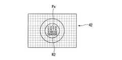
図6は、本実施形態の変形例1におけるアライメント量の算出方法を示す図である。本変形例では、パソコン45は、上述のように第2撮像素子で取得された反射光束像を含む画像の2値化処理を行った後、内部領域R2の内側に位置する画素Pxの総数Nをカウントし、これを内部領域R2の面積を示すアライメント量として表示部46に表示する。内部領域R2の面積は、測定面Sa等が平面であれば、測定面Sa等が光軸X1に対して垂直となるときに最小となり、総画素数Nも最小となる。したがって、使用者は、総画素数Nが最小となるようにステージ6を調節することにより、被検物S等のアライメント調節を容易に行うことができる。 FIG. 6 is a diagram illustrating an alignment amount calculation method according to the first modification of the present embodiment. In the present modification, the
なお、最適なアライメント状態を示す総画素数Nは、測定面の形状により変化するため、実際には個々の測定面等において想定される調節完了時の総画素数Nalgを算出し、現在の総画素数Nと並列表示等することにより、アライメント調節の指標とすればよい。表示形式としては、数値のほか、棒グラフ等のインジケータとして表示することも可能である。Note that the total number of pixels N indicating the optimum alignment state varies depending on the shape of the measurement surface. Therefore, in actuality, the total number of pixels Nalg upon completion of adjustment assumed on each measurement surface is calculated, By performing parallel display with the total number of pixels N, it may be used as an index for alignment adjustment. The display format can be displayed as an indicator such as a bar graph in addition to numerical values.
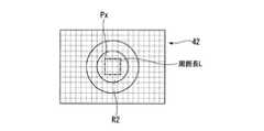
図7は、本実施形態の変形例2におけるアライメント量の算出方法を示す図である。本変形例では、上述のように反射光束像を含む画像の2値化処理を行った後、パソコン45は、内部領域R2の内側に位置する画素のうち、図7に示すように最外縁の画素を結んだ長さである周囲長Lを算出する。図7では、説明の便宜のために画素Pxが大きく表示されているため、周囲長Lを示す図形は、円形でなく正方形となっているが、実際には画素Pxは小さく、かつ多数存在するため、周囲長Lを示す図形は、内部領域R2とほぼ同一の形状となる。算出された周囲長Lは、パソコン45の記憶領域に格納される。
さらに、パソコン45は、変形例1と同様の手順で内部領域R2の総画素数Nをカウントし、周囲長Lと総画素数Nとを用いてアライメント量を算出する。算出のための式はいくつか挙げられるが、例えば、下記の数3の式を用いることができる。数3を用いる場合、測定面Sa等が平面であれば、測定面Sa等が光軸X1に対して垂直となるときにアライメント量が1となるため、使用者はアライメント量を1に近づけるようにしてアライメント調節を行えばよい。FIG. 7 is a diagram illustrating a method for calculating the alignment amount in the second modification of the present embodiment. In the present modification, after performing the binarization processing of the image including the reflected light beam image as described above, the
Further, the
このほか、アライメント量の算出には、下記数4、数5の式等も使用可能である。数4の場合、測定面Sa等が平面のとき、測定面Saが光軸X1に対して垂直になるとアライメント量は4π分の1となり、数5の場合は1となる。 In addition, the following
以上、本発明の各実施形態について説明したが、本発明の技術範囲は上記実施形態に限定されるものではなく、本発明の趣旨を逸脱しない範囲において各実施形態の構成要素の組み合わせを変えたり、各構成要素に種々の変更を加えたり、削除したりすることが可能である。 The embodiments of the present invention have been described above. However, the technical scope of the present invention is not limited to the above-described embodiments, and combinations of components in the embodiments may be changed without departing from the spirit of the present invention. Various changes can be added to or deleted from each component.
例えば、上述の各実施形態では、アライメント状態確認部が、反射光束の光路において焦点よりも遠い位置に配置される例を説明したが、アライメント状態を反映する反射光束像の変化は、反射光束の焦点と異なる位置で反射光束像を撮像すれば捉えることができる。したがって、反射光束の光路において焦点よりも近い位置にアライメント状態確認部が配置されてもよい。 For example, in each of the above-described embodiments, the example in which the alignment state confirmation unit is disposed at a position farther than the focal point in the optical path of the reflected light beam is described. However, the change in the reflected light beam image that reflects the alignment state is The reflected light beam image can be captured at a position different from the focal point. Therefore, the alignment state confirmation unit may be disposed at a position closer to the focal point in the optical path of the reflected light beam.
また、上述したアライメント量が、複数種類算出されて表示部に表示されてもよい。
さらに、アライメント状態確認部で取得された反射光束像を含む画像が表示部に表示されず、観察光学系で取得された画像と算出されたアライメント量だけが表示部に表示される構成としてもよい。Further, a plurality of types of alignment amounts described above may be calculated and displayed on the display unit.
Furthermore, an image including the reflected light beam image acquired by the alignment state confirmation unit may not be displayed on the display unit, and only the image acquired by the observation optical system and the calculated alignment amount may be displayed on the display unit. .
1 光源
15、60 対物光学系
20 分光器(測光手段)
40 アライメント状態確認部
42 第2撮像素子(撮像手段)
41 コリメータレンズ
45 パソコン(演算部)
46 表示部
50 測光装置
61 凹面鏡
62 凸面鏡
L 周囲長
R2 内部領域
S 被検物
Sa 測定面1
40 Alignment
41
46
Claims (7)
Translated fromJapanese前記反射光束の光路上に配置され、前記反射光束の焦点と異なる位置において前記反射光束の像を撮像する撮像手段を有するアライメント状態確認部と、
前記撮像手段で撮像した前記反射光束の像により得られた情報を表示する表示部と、
を備えることを特徴とする測光装置。A photometric device comprising: a light source; an objective optical system that guides a measurement light beam emitted from the light source to a test object; and a photometry unit that measures a reflected light beam reflected by the measurement surface of the test object. There,
An alignment state confirmation unit that is disposed on the optical path of the reflected light beam and has an imaging unit that captures an image of the reflected light beam at a position different from the focal point of the reflected light beam;
A display unit for displaying information obtained from the image of the reflected light beam imaged by the imaging unit;
A photometric device comprising:
Priority Applications (1)
| Application Number | Priority Date | Filing Date | Title |
|---|---|---|---|
| JP2010096932AJP5385206B2 (en) | 2010-04-20 | 2010-04-20 | Photometric device |
Applications Claiming Priority (1)
| Application Number | Priority Date | Filing Date | Title |
|---|---|---|---|
| JP2010096932AJP5385206B2 (en) | 2010-04-20 | 2010-04-20 | Photometric device |
Publications (2)
| Publication Number | Publication Date |
|---|---|
| JP2011226916A JP2011226916A (en) | 2011-11-10 |
| JP5385206B2true JP5385206B2 (en) | 2014-01-08 |
Family
ID=45042423
Family Applications (1)
| Application Number | Title | Priority Date | Filing Date |
|---|---|---|---|
| JP2010096932AExpired - Fee RelatedJP5385206B2 (en) | 2010-04-20 | 2010-04-20 | Photometric device |
Country Status (1)
| Country | Link |
|---|---|
| JP (1) | JP5385206B2 (en) |
Families Citing this family (1)
| Publication number | Priority date | Publication date | Assignee | Title |
|---|---|---|---|---|
| CN119064273A (en)* | 2024-09-18 | 2024-12-03 | 广东歌得智能装备有限公司 | A reflectivity and transmittance testing device for tiny objects and curved objects |
Family Cites Families (7)
| Publication number | Priority date | Publication date | Assignee | Title |
|---|---|---|---|---|
| JPH05332934A (en)* | 1992-06-03 | 1993-12-17 | Jasco Corp | Spectroscope |
| JP3667397B2 (en)* | 1995-09-04 | 2005-07-06 | 日本分光株式会社 | Raman spectrometer |
| JPH10122823A (en)* | 1996-08-27 | 1998-05-15 | Olympus Optical Co Ltd | Positioning method and height measuring device using the method |
| JP5172203B2 (en)* | 2007-05-16 | 2013-03-27 | 大塚電子株式会社 | Optical characteristic measuring apparatus and measuring method |
| JP5172204B2 (en)* | 2007-05-16 | 2013-03-27 | 大塚電子株式会社 | Optical characteristic measuring apparatus and focus adjustment method |
| JP2010019630A (en)* | 2008-07-09 | 2010-01-28 | Tokyo Institute Of Technology | Microscopic spectroscopic device |
| JP2010216864A (en)* | 2009-03-13 | 2010-09-30 | Olympus Corp | Photometric apparatus |
- 2010
- 2010-04-20JPJP2010096932Apatent/JP5385206B2/ennot_activeExpired - Fee Related
Also Published As
| Publication number | Publication date |
|---|---|
| JP2011226916A (en) | 2011-11-10 |
Similar Documents
| Publication | Publication Date | Title |
|---|---|---|
| JP5489392B2 (en) | Optical system evaluation apparatus, optical system evaluation method, and optical system evaluation program | |
| JP5172204B2 (en) | Optical characteristic measuring apparatus and focus adjustment method | |
| EP1785714B1 (en) | Lens evaluation device | |
| JP5172203B2 (en) | Optical characteristic measuring apparatus and measuring method | |
| JP4922823B2 (en) | 3D shape measuring device | |
| JP4937686B2 (en) | Lens evaluation device | |
| US11954766B2 (en) | Method for carrying out a shading correction and optical observation device system | |
| JP2018119907A (en) | Method for adjusting measurement surface, method for measuring film thickness, and film thickness measuring device | |
| JP2008039750A (en) | Device for height measuring | |
| JP2010216864A (en) | Photometric apparatus | |
| JP2009109315A (en) | Light measuring device and scanning optical system | |
| WO2017175303A1 (en) | Sample shape measurement method and sample shape measurement device | |
| JP2008116900A (en) | Interference objective lens, and interference microscope apparatus with interference objective lens | |
| JP5385206B2 (en) | Photometric device | |
| WO2012165549A1 (en) | Dimension measuring apparatus | |
| US20240065525A1 (en) | Method, computer program, and data processing unit for creating at least one correction value for correcting fluorescence intensities in a fluorescence image, and optical observation system | |
| JP2010091468A (en) | Aberration measurement apparatus | |
| JP2005017127A (en) | Interferometer and shape measuring device | |
| JPH11264800A (en) | Inspection device | |
| JP6255305B2 (en) | Optical microscope | |
| JPH11230829A (en) | Microspectroscope and method for measuring spectral data using the same | |
| JP2010139419A (en) | Shape measuring instrument | |
| JP2011095512A (en) | Confocal microscope | |
| JP2012122757A (en) | Photometric device | |
| JP2010085272A (en) | Optical evaluation device |
Legal Events
| Date | Code | Title | Description |
|---|---|---|---|
| A621 | Written request for application examination | Free format text:JAPANESE INTERMEDIATE CODE: A621 Effective date:20130207 | |
| A977 | Report on retrieval | Free format text:JAPANESE INTERMEDIATE CODE: A971007 Effective date:20130830 | |
| TRDD | Decision of grant or rejection written | ||
| A01 | Written decision to grant a patent or to grant a registration (utility model) | Free format text:JAPANESE INTERMEDIATE CODE: A01 Effective date:20130917 | |
| A61 | First payment of annual fees (during grant procedure) | Free format text:JAPANESE INTERMEDIATE CODE: A61 Effective date:20131003 | |
| R151 | Written notification of patent or utility model registration | Ref document number:5385206 Country of ref document:JP Free format text:JAPANESE INTERMEDIATE CODE: R151 | |
| S531 | Written request for registration of change of domicile | Free format text:JAPANESE INTERMEDIATE CODE: R313531 | |
| R350 | Written notification of registration of transfer | Free format text:JAPANESE INTERMEDIATE CODE: R350 | |
| R250 | Receipt of annual fees | Free format text:JAPANESE INTERMEDIATE CODE: R250 | |
| R250 | Receipt of annual fees | Free format text:JAPANESE INTERMEDIATE CODE: R250 | |
| R250 | Receipt of annual fees | Free format text:JAPANESE INTERMEDIATE CODE: R250 | |
| R250 | Receipt of annual fees | Free format text:JAPANESE INTERMEDIATE CODE: R250 | |
| R250 | Receipt of annual fees | Free format text:JAPANESE INTERMEDIATE CODE: R250 | |
| R250 | Receipt of annual fees | Free format text:JAPANESE INTERMEDIATE CODE: R250 | |
| LAPS | Cancellation because of no payment of annual fees |