JP5383798B2 - System and method for marking three-dimensional film - Google Patents
System and method for marking three-dimensional filmDownload PDFInfo
- Publication number
- JP5383798B2 JP5383798B2JP2011513465AJP2011513465AJP5383798B2JP 5383798 B2JP5383798 B2JP 5383798B2JP 2011513465 AJP2011513465 AJP 2011513465AJP 2011513465 AJP2011513465 AJP 2011513465AJP 5383798 B2JP5383798 B2JP 5383798B2
- Authority
- JP
- Japan
- Prior art keywords
- mark
- image
- color
- stereoscopic
- predetermined position
- Prior art date
- Legal status (The legal status is an assumption and is not a legal conclusion. Google has not performed a legal analysis and makes no representation as to the accuracy of the status listed.)
- Expired - Fee Related
Links
Images


Classifications
- G—PHYSICS
- G06—COMPUTING OR CALCULATING; COUNTING
- G06T—IMAGE DATA PROCESSING OR GENERATION, IN GENERAL
- G06T1/00—General purpose image data processing
- G06T1/0021—Image watermarking
- G06T1/0028—Adaptive watermarking, e.g. Human Visual System [HVS]-based watermarking
- G—PHYSICS
- G03—PHOTOGRAPHY; CINEMATOGRAPHY; ANALOGOUS TECHNIQUES USING WAVES OTHER THAN OPTICAL WAVES; ELECTROGRAPHY; HOLOGRAPHY
- G03B—APPARATUS OR ARRANGEMENTS FOR TAKING PHOTOGRAPHS OR FOR PROJECTING OR VIEWING THEM; APPARATUS OR ARRANGEMENTS EMPLOYING ANALOGOUS TECHNIQUES USING WAVES OTHER THAN OPTICAL WAVES; ACCESSORIES THEREFOR
- G03B35/00—Stereoscopic photography
- G03B35/18—Stereoscopic photography by simultaneous viewing
- H—ELECTRICITY
- H04—ELECTRIC COMMUNICATION TECHNIQUE
- H04N—PICTORIAL COMMUNICATION, e.g. TELEVISION
- H04N13/00—Stereoscopic video systems; Multi-view video systems; Details thereof
- H04N13/10—Processing, recording or transmission of stereoscopic or multi-view image signals
Landscapes
- Physics & Mathematics (AREA)
- General Physics & Mathematics (AREA)
- Engineering & Computer Science (AREA)
- Multimedia (AREA)
- Signal Processing (AREA)
- Theoretical Computer Science (AREA)
- Testing, Inspecting, Measuring Of Stereoscopic Televisions And Televisions (AREA)
Description
Translated fromJapanese本発明は、コンピュータグラフィック処理及びディスプレイシステムに関し、より詳細には、立体フィルムにマーク付けするシステム及び方法に関する。 The present invention relates to computer graphic processing and display systems, and more particularly to systems and methods for marking stereoscopic film.
立体フィルムの画像形成は、僅かに異なる視点から撮影された、あるシーンの少なくとも2つの画像を視覚的に結合して、3次元(3D)の奥行きの幻想を生成するプロセスである。この技術は、人間の目がある距離で離れて配置され、従って同じシーンを正確に見ない事実に依存する。それぞれの目に異なる視点からの画像を供給することで、見る人の目は、奥行きを知覚するようにトリックにかかる。典型的に、2つの異なる視点が提供された場合、コンポーネント画像は、参照画像及び相補画像としてもそれぞれ知られる、「左」画像及び「右」画像と呼ばれる。しかし、当業者であれば、立体画像を形成するため、2を超える視点が結合される場合があることを認識するであろう。 Stereo film imaging is the process of visually combining at least two images of a scene taken from slightly different viewpoints to create a three-dimensional (3D) depth illusion. This technique relies on the fact that the human eye is located at a distance and therefore does not see the same scene accurately. By supplying images from different viewpoints to each eye, the viewer's eyes take a trick to perceive depth. Typically, if two different viewpoints are provided, the component images are referred to as “left” and “right” images, also known as reference images and complementary images, respectively. However, those skilled in the art will recognize that more than two viewpoints may be combined to form a stereoscopic image.
映画からデジタルシネマへの遷移は、3D及びリアルタイム伝送のようなシネマの新たな機会を形成している。3Dコンテンツについて、立体コンテンツが予知できる将来にデジタルシネマを支配することが期待される。立体デジタルシネマは、単一のプロジェクタを使用して2つの画像を投影することを含む。以下に記載されるように、デジタルシネマにおいて立体コンテンツを投影する3つの技術が現在存在する。 The transition from cinema to digital cinema has created new opportunities for cinema, such as 3D and real-time transmission. As for 3D content, it is expected to dominate digital cinema in the future when stereoscopic content can be predicted. Stereoscopic digital cinema involves projecting two images using a single projector. As described below, there are currently three techniques for projecting stereoscopic content in a digital cinema.
光学的な変更をもたないアクティブグラスを使用する。この技術では、プロジェクタは、標準のスクリーンに左画像と右画像を交互にする。ユーザ又はビューアは、IRコントローラを使用してコンテンツに同期されるアクティブグラスを装着する。 Use active glasses without optical changes. In this technique, the projector alternates left and right images on a standard screen. The user or viewer wears an active glass that is synchronized to the content using the IR controller.
円偏光子をもつパッシブグラスを使用する。これは、現在最も広く配置されるシステムである。また、プロジェクタは、シルバースクリーンに左画像と右画像を交互にする。偏光ユニットは、プロジェクタの前に配置される。ユーザ又はビューアは、特別のパッシブグラスを装着することが要求される。 Use passive glass with circular polarizer. This is the most widely deployed system at present. The projector alternates the left image and the right image on the silver screen. The polarization unit is disposed in front of the projector. Users or viewers are required to wear special passive glasses.
ドルビー3D技術。この技術では、色が6つのバンドに分割され、それぞれの目に3つのバンドが割り当てられる。プロジェクタは、左画像と右画像とを交互にし、ユーザ又はビューアは、特別のカラーフィルタリンググラスを装着する。 Dolby 3D technology. In this technique, the color is divided into six bands, and three bands are assigned to each eye. The projector alternates between left and right images, and the user or viewer wears a special color filtering glass.
上述されたように、全ての技術は、コンテンツを見るためにメガネを装着することを要求する。メガネを装着しなければ、3Dコンテンツは歪んで見える。 As mentioned above, all technologies require wearing glasses to view content. If glasses are not worn, 3D content looks distorted.
シネマでは、たとえばムービープレビューといった商業広告は典型的に2次元(2D)であることが一般的である。次いで、3D効果を実現するため、何時特別のメガネをビューアに装着させるべきかを知らせることが必要である。ビューアに何時メガネを装着させるべきかを知らせるため、シネマは、上下に移動するカーテンを使用するか、アナウンスを行う必要がある。これは、番組又は映画の間に、3Dから2Dへ、2Dから3Dへの多くの遷移が潜在的に存在するので、困難になる。したがって、ビューアに不快感を与えない立体フィルムの視聴者に遷移のメッセージを提供する技術について必要が存在する。 In cinema, commercial advertisements, such as movie previews, are typically two-dimensional (2D). It is then necessary to inform the viewer when to wear special glasses to achieve the 3D effect. In order to let the viewer know when to wear glasses, the cinema needs to use a curtain that moves up and down or make an announcement. This is difficult because there are potentially many transitions from 3D to 2D, 2D to 3D during a program or movie. Therefore, there is a need for a technique for providing a transition message to a viewer of a stereoscopic film that does not cause discomfort to the viewer.
さらに、動画の劇場での上映に関連した海賊行為の懸念が知られている。ひとたび映画の配給業者が劇場での上映のために上映者に映画に関する印刷物を配給すると、その製品に対する所定の程度の制御が失われる。アナログであるかデジタルであるかに関わらず、ある劇場において映画を上映する過程で、劇場における顧客は、上映の間に、たとえばハンドヘルドカムコーダを使用して、映画をこっそりと記録する場合がある。結果として、比較的高品質の違法なコピーが行われる可能性がある。ある映画の係る違法な「海賊行為」による複製は、インターネットを通して配信されるか又はハードコピー(ビデオCD又はDVD)を使用することで流通され、これにより、合法的な映画配信の経済価値が低減する。インターネット及び手頃な価格の高品質の記録装置の出現により、この問題は、近年において益々深刻になっている。したがって、映画の合法的な視聴者には見えない、映画の違法な複製に対する警告メッセージを提供する技術が更に必要とされる。 In addition, there are known piracy concerns related to movie theater screenings. Once a movie distributor distributes prints related to a movie to a shower for theater screening, a certain degree of control over the product is lost. Regardless of whether it is analog or digital, in the process of showing a movie in a theater, a customer in the theater may secretly record the movie during the show, for example using a handheld camcorder. As a result, there may be a relatively high quality illegal copy. Such illegal “piracy” copies of a movie are distributed over the Internet or distributed using hardcopy (video CD or DVD), which reduces the economic value of legal movie distribution. To do. With the advent of the Internet and affordable high-quality recording devices, this problem has become more serious in recent years. Accordingly, there is a further need for a technique that provides a warning message for illegal duplication of a movie that is not visible to a legitimate viewer of the movie.
メタメリックな色で立体映画をマーク付けするシステム及び方法が提供される。本システム及び方法は、第一の色のマークを左画像に付加し、第二の異なる色(たとえば相補的な色)を有するマークを右画像に付加するものであり、視聴されたとき、マークは、所定の条件下で目で見る事ができない。3次元(3D)モードで視聴されたとき、左のマーク及び画像は、1つのマークに結合又は統合され、1つのマークの全ての画素は、同じ色からなる。 Systems and methods for marking stereoscopic movies with metameric colors are provided. The system and method adds a first color mark to the left image and a second different color (eg, a complementary color) to the right image, and when viewed, Is invisible under certain conditions. When viewed in three-dimensional (3D) mode, the left mark and image are combined or merged into one mark, and all pixels of one mark are of the same color.
本発明の開示の1態様によれば、ある映画にマーク付けする方法が提供される。本方法は、第一の画像と第二の画像とを含む立体画像を取得するステップ(202)、第一の色を有する第一のマークを第一の画像の予め決定された位置に付加するステップ(204)、及び第一のマークの第一の色とは異なる第二の色を有する第二のマークを、第二の画像の実質的に同じ予め決定された位置に付加するステップ(206)を含む。3次元モードで視聴されたとき、第一のマークと第二のマークは、1つの色からなる1つのマークに結合される。 According to one aspect of the present disclosure, a method for marking a movie is provided. The method obtains a stereoscopic image including a first image and a second image (202), and adds a first mark having a first color to a predetermined position of the first image. Step (204) and adding a second mark having a second color different from the first color of the first mark to substantially the same predetermined position of the second image (206). )including. When viewed in a three-dimensional mode, the first mark and the second mark are combined into one mark of one color.
本発明の更なる態様によれば、ある映画にマーク付けするシステムが提供される。本システムは、第一の画像と第二の画像とを含む立体画像を取得する手段、第一の色を有する第一のマークを第二の画像の予め決定された位置に付加し、第一のマークの第一の色とは異なる第二の色を有する第二のマークを、第二の画像において、第一の画像と実質的な同じ予め決定された位置に付加するマーキングモジュールを含み、3次元モードで視聴されたとき、第一のマークと第二のマークは、1つの色からなる1つのマークに結合される。 According to a further aspect of the invention, a system for marking a movie is provided. The system includes means for acquiring a stereoscopic image including a first image and a second image, adding a first mark having a first color to a predetermined position of the second image, A marking module for adding a second mark having a second color different from the first color of the mark at the second image at substantially the same predetermined position as the first image; When viewed in a three-dimensional mode, the first mark and the second mark are combined into one mark of one color.
この開示の別の態様によれば、本発明に従ってマーク付けされる立体画像が提供される。立体画像は、予め決定された位置において第一の色を有する第一のマークを有する第一の画像と、第一の画像における予め決定された位置と実質的に同じ位置において第二の色を有する第二のマークを有する第二の画像とを含み、立体画像が3次元画像として視聴されたとき、第一のマークと第二のマークは1つの色からなる1つのマークとして結合され、1つのマークは、3次元画像の視聴者により見る事ができない。 According to another aspect of this disclosure, a stereoscopic image marked according to the present invention is provided. The stereoscopic image has a first image having a first mark having a first color at a predetermined position, and a second color at a position substantially the same as the predetermined position in the first image. And when the stereoscopic image is viewed as a three-dimensional image, the first mark and the second mark are combined as one mark composed of one color. The two marks cannot be seen by the viewer of the 3D image.
本発明のこれらの態様、特徴及び利点並びに他の態様、特徴及び利点は、添付図面と共に読まれたとき、好適な実施の形態の以下の詳細な説明から明らかとなるであろう。図面において、同じ参照符号は、図面を通して同じエレメントを示す。
図面は、本発明の概念を説明するためのものであり、必ずしも、本発明を例示する唯一の可能なコンフィギュレーションではない。
The drawings are for purposes of illustrating the concepts of the invention and are not necessarily the only possible configuration for illustrating the invention.
図示されるエレメントはハードウェア、ソフトウェア又はその組み合わせの様々な形態で実現される場合があることを理解されたい。好ましくは、これらのエレメントは、プロセッサ、メモリ及び入力/出力インタフェースを含む1以上の適切にプログラムされた汎用装置でハードウェア及びソフトウェアの組み合わせで実現される。 It should be understood that the elements shown may be implemented in various forms of hardware, software or combinations thereof. Preferably, these elements are implemented in a combination of hardware and software on one or more appropriately programmed general purpose devices including a processor, memory and input / output interfaces.
本実施の形態は、本発明の原理を例示するものである。したがって、当業者であれば、本実施の形態で明示的に記載又は図示されていないが、本発明の原理を実施し、本発明の精神及び範囲に含まれる様々なアレンジメントを創作することができることを理解されたい。 This embodiment exemplifies the principle of the present invention. Accordingly, those skilled in the art can implement the principles of the present invention and create various arrangements that fall within the spirit and scope of the present invention, although not explicitly described or illustrated in the present embodiment. I want you to understand.
本明細書で引用される全ての例及び条件付き言語は、本発明の原理及び当該技術分野を促進するために本発明者により寄与される概念の理解において読者を支援するためのものであり、係る特に引用される例及び条件に限定されることがないとして解釈されるべきである。 All examples and conditional languages cited herein are intended to assist the reader in understanding the principles of the invention and the concepts contributed by the inventors to promote the art, It should be construed as not limited to such specifically cited examples and conditions.
さらに、本発明の原理、態様及び実施の形態、並びに本発明の特別の例を引用する全ての説明は、本発明の構造的及び機能的に等価なものを包含することが意図される。さらに、係る等価なものは、現在知られている等価なものと、将来に開発される等価なもの、すなわち構造に関わらず、同じ機能を実行する開発されたエレメントを含むことが意図される。 Moreover, all principles, aspects and embodiments of the invention, as well as all descriptions reciting particular examples of the invention are intended to encompass the structural and functional equivalents of the invention. Furthermore, such equivalents are intended to include elements that have been developed that perform the same function, regardless of what is currently known and equivalents that will be developed in the future, ie, structures.
従って、たとえば、本実施の形態で与えられるブロック図は、本発明の原理を実施する例示的な回路の概念図を表すことが当業者により理解されるであろう。同様に、フローチャート、フローダイアグラム、状態遷移図、擬似コード等は、コンピュータ読み取り可能な媒体で実質的に表され、コンピュータ又はプロセッサが明示的に示されているか否かに関わらず、係るコンピュータ又はプロセッサにより実行される様々なプロセスを表すことが理解される。 Thus, for example, it will be appreciated by those skilled in the art that the block diagram provided in the present embodiment represents a conceptual diagram of an exemplary circuit implementing the principles of the present invention. Similarly, flowcharts, flow diagrams, state transition diagrams, pseudocode, etc. are substantially represented by computer-readable media, whether or not such computer or processor is explicitly shown. It is understood that it represents various processes performed by.
図示される様々なエレメントの機能は、適切なソフトウェアに関連してソフトウェアを実行可能なハードウェアの使用と同様に、専用のハードウェアの使用により提供される場合がある。プロセッサにより提供されたとき、機能は、1つの専用プロセッサにより、1つの共有プロセッサにより、或いはそのうちの幾つかが共有される複数の個々のプロセッサにより提供される場合がある。さらに、用語「プロセッサ」又は「コントローラ」の明示的な使用は、ソフトウェアを実行可能なハードウェアを排他的に示すように解釈されるべきではなく、限定されることなしに、デジタルシグナルプロセッサ(DSP)ハードウェア、ソフトウェアを記憶するリードオンリメモリ(ROM)、ランダムアクセスメモリ(RAM)、及び不揮発性メモリを暗黙的に含む場合がある。 The functionality of the various elements shown may be provided through the use of dedicated hardware, as well as the use of hardware capable of executing software in conjunction with appropriate software. When provided by a processor, the functionality may be provided by one dedicated processor, by one shared processor, or by multiple individual processors, some of which are shared. Furthermore, the explicit use of the term “processor” or “controller” should not be construed to indicate exclusively hardware capable of executing software, but without limitation, digital signal processors (DSPs). ) Implicitly includes hardware, read only memory (ROM) for storing software, random access memory (RAM), and non-volatile memory.
コンベンショナル及び/又はカスタムな他のハードウェアが含まれる場合もある。同様に、図示される任意のスイッチは概念的なものである。それらの機能は、プログラムロジックの動作を通して、専用ロジックを通して、プログラム制御と専用ロジックのやり取りを通して、又は手動的に実行される場合があり、特定の技術は、文脈からより詳細に理解されるように実現者により選択可能である。 Other conventional and / or custom hardware may also be included. Similarly, any switches shown are conceptual. These functions may be performed through the operation of program logic, through dedicated logic, through the exchange of program control and dedicated logic, or manually, as certain techniques are understood in more detail from the context. It can be selected by the implementer.
本発明の請求項では、特定の機能を実行する手段として表現されるエレメントは、たとえばa)その機能を実行する回路エレメントの組み合わせ、又はb)その機能を実行するそのソフトウェアを実行する適切な回路と組み合わされる、ファームウェア、マイクロコード等を含む任意の形態でのソフトウェア、を含むその機能を実行する任意のやり方を包含することが意図される。係る請求項により定義される開示は、様々な引用される手段により提供される機能が請求項が求めるやり方で結合され、纏められる事実にある。従って、それらの機能を提供する任意の手段は本実施の形態で示されるものに等価であると見なされる。 In the claims of the present invention, an element expressed as a means for performing a specific function is, for example, a) a combination of circuit elements that perform that function, or b) a suitable circuit that executes that software that performs that function. It is intended to encompass any way of performing that function, including firmware, software in any form, including microcode, etc., in combination with. The disclosure defined by such claims lies in the fact that the functions provided by the various cited means are combined and grouped in the manner required by the claims. Accordingly, any means that provides these functions are considered equivalent to those shown in this embodiment.
立体3Dの機能は、過去2年間で多数の劇場に付加されている。2009年までに5000を超えてステレオ再生が利用可能になることが期待される。市場で利用可能な現在の立体システムは、3Dコンテンツを見るため、たとえば偏光メガネ又は色選択グラスといった特殊メガネをユーザが装着することが必要とされる。大部分の劇場は、2Dの商業広告と3D映画との間の遷移時間の間にアナウンス又は他のメカニズムを採用しない。本発明で提供される立体情報は、ダイレクトな視覚的効果を伝えるものであり、したがって視聴者は、特殊メガネを何時装着すべきかを認識することができる。同じプロジェクタ及びメガネが2Dコンテンツに採用されたと仮定すると、係る立体情報は警告メッセージとして採用される一方、特殊メガネにより視聴者に不快感を与えず、すなわちメッセージはユーザ又は視聴者に見えない。 The stereoscopic 3D function has been added to many theaters over the past two years. By 2009, it is expected that stereo playback will be available beyond 5000. Current stereoscopic systems available on the market require users to wear special glasses, such as polarized glasses or color selection glasses, for viewing 3D content. Most theaters do not employ announcements or other mechanisms during the transition time between 2D commercial advertisements and 3D movies. The three-dimensional information provided by the present invention conveys a direct visual effect, so that the viewer can recognize when to wear special glasses. Assuming that the same projector and glasses are employed for 2D content, such stereoscopic information is employed as a warning message, while the special glasses do not make the viewer uncomfortable, i.e., the message is not visible to the user or the viewer.
メタメリックな色で立体映画にマーク付けするシステム及び方法が提供され、本システム及び方法は、左の画像を第一のマークでマーク付けし、右の画像を異なる色を有する第二の同じマークでマーク付けするものであり、視聴されたとき、マークは、所定の条件下で見えない。本発明の技術は、たとえばある映画のコンテンツにおけるメッセージ、オブジェクトの配置により、コンテンツが3Dにあるか又は2Dにあるかをユーザ又は視聴者に通知することが可能となる。これは、ユーザがコンテンツを正しく見るために特殊なメガネを装着することが必要であるので重要である。このように、3Dモードにおいて、本発明に従ってマーク付けされた映画又はコンテンツは、視聴者が3D体験のために特殊メガネを何時装着すべきかのタイミングに関する情報を伝達し、2Dモードにおいて、同じ環境下で、係る情報は、違法な記録に対する警告メッセージとして作用する。たとえば、カムコーダの前の特殊フィルタを使用した2Dコンテンツへの3Dコンテンツの違法な記録の場合、係る立体情報は、目で見る事ができ、画質を低下したときに警告メッセーとして使用することができる。 A system and method for marking a stereoscopic movie with a metameric color is provided, the system and method marking a left image with a first mark and a right image with a second same mark having a different color. Marked and when viewed, the mark is not visible under certain conditions. The technology of the present invention can notify the user or viewer whether the content is in 3D or 2D, for example, by arrangement of messages and objects in the content of a movie. This is important because it is necessary for the user to wear special glasses to see the content correctly. Thus, in 3D mode, a movie or content marked according to the present invention conveys information regarding when the viewer should wear special glasses for a 3D experience, and in 2D mode, under the same environment Thus, such information acts as a warning message for illegal recording. For example, in the case of illegal recording of 3D content into 2D content using a special filter in front of the camcorder, such 3D information can be seen with the eyes and can be used as a warning message when the image quality is degraded. .
図面を参照して、本発明の実施の形態に係る例示的なシステム構成要素は、図1に示される。スキャニング装置103は、たとえばカメラのオリジナルのネガフィルムといったフィルムプリント104を、たとえばシネオンフォーマット又はSMPTE(Society of Motion Picture and Television Engineers)DPX(Digital Picture Exchange)ファイルといったデジタルフォーマットにスキャニングするために設けられる。スキャニング装置103は、たとえばテレシネ、又はビデオ出力でArri LocPro(登録商標)のような映画からビデオ出力を生成する任意の装置を有する。代替的に、(たとえば既にコンピュータ読み取り可能な形式にあるファイルといった)ポストプロダクションプロセス又はデジタルシネマ106からのファイルは、直接に使用することができる。コンピュータ読み取り可能なファイルの潜在的な源は、AVID(登録商標)エディタ、DPXファイル、D5テープ等である。 Referring to the drawings, exemplary system components according to an embodiment of the present invention are shown in FIG. The scanning device 103 is provided for scanning a
スキャニングされたフィルムプリントは、たとえばコンピュータといったポストプロセッシング装置102に入力される。コンピュータは、1以上の中央処理装置(CPU)、ランダムアクセスメモリ(RAM)及び/又はリードオンリメモリ(ROM)のようなメモリ、及び、キーボード、カーソル制御装置(たとえばマウス又はジョイスティック)のような入力/出力(I/O)ユーザインタフェース112、並びに表示装置のようなハードウェアを有する様々公知のコンピュータプラットフォームの何れかで実現される。また、コンピュータプラットフォームは、オペレーティングシステム及びマイクロ命令コードを含む。本実施の形態で記載される様々な処理及び機能は、オペレーティングシステムを介して実行されるマイクロ命令コードの一部又はソフトウェアアプリケーションプログラムの一部(或いはその組み合わせ)の何れかである場合がある。1実施の形態では、ソフトウェアアプリケーションプログラムは、ポストプロセッシング装置102のような適切なコンピュータにアップロードされて実行されるプログラム記憶装置で実施される。さらに、様々な他の周辺装置は、パラレルポート、シリアルポート又はユニバーサルシリアルバス(USB)のような様々なインタフェース及びバス構造によりコンピュータプラットフォームに接続される場合がある。他の周辺装置は、更なる記憶装置124及びプリンタ128を含む場合がある。プリンタ128は、たとえばあるシーン又は複数のシーンが以下に記載される技術を使用して変更され又はマークアップされるフィルムの立体のマークアップされたバージョンといった、フィルム126の改訂されたバージョンを印刷するために利用される。 The scanned film print is input to a post-processing device 102 such as a computer. The computer has one or more central processing units (CPU), memory such as random access memory (RAM) and / or read only memory (ROM), and input such as a keyboard, cursor control device (eg mouse or joystick) Implemented on any of a variety of known computer platforms having hardware such as an output / output (I / O)
代替的に、(たとえば外部のハードドライブ124に記憶されるデジタルシネマといった)コンピュータ読み取り可能な形式106に既にあるファイル/フィルムのプリントは、コンピュータ102に直接に入力される。なお、本実施の形態で使用される用語「フィルム」は、フィルムプリント又はデジタルシネマの何れかを示す場合がある。 Alternatively, file / film prints already in computer readable form 106 (eg, digital cinema stored on external hard drive 124) are input directly to computer 102. Note that the term “film” used in the present embodiment may indicate either film print or digital cinema.
ソフトウェアプログラムは、テキストメッセージ、オブジェクト、ロゴ等のようなマークで立体のペアのそれぞれの画像にマーク付けする、メモリ110に記憶されるマーキングモジュール114を含む。マーキングモジュール114は、少なくとも2つの色を有する第一のマークを立体のペアの第一又は左目の画像に付け、たとえば相補的な色である少なくとも2つの異なる色を有する同じ第二のマークを第二の又は右目の画像(すなわち相補的な画像)に付ける。第一のマーク及び第二のマークの色は、メタメリックな色であると考えられる。これは、特殊な3Dメガネによる再生の間に2つの画像を見たとき、第一及び第二のマークは1つの色に結合又は統合され、視聴者に見る事ができないからである。 The software program includes a marking module 114 stored in the
マーキングモジュール114は、第一のマークの少なくとも2つの色を選択し、第二のマークの少なくとも2つの異なる色を決定するカラーアナライザ116を含む。さらに、カラーアナライザ116は、第一又は第二の画像における少なくとも1つの色を決定し、少なくとも1つの色を少なくとも2つのメタメリックな色にスペクトル的に分割する。 The marking module 114 includes a
マーキングモジュール114は、同じシーン又はショットに属する立体のペアの多数の連続するフレームを決定又は選択するシーケンスアナライザ118を更に含む。シーケンスアナライザ118は、少なくとも2つの連続するフレーム内のある画像における位置について、少なくとも1つの条件が満足されるかを判定する。たとえば、あるマークが他のコンテンツを持つ画像において配置される場合、シーケンスアナライザ118は、そのマークについて選択される位置が変化したか、従ってマークが視聴者にとって目障りになっているかを判定する。 The marking module 114 further includes a
1実施の形態では、マーキングモジュール114は、ある画像からオブジェクトを分割するオブジェクトセグメンタ120を含む。オブジェクトセグメンタ120は、ある画像におけるオブジェクトを識別し、カラーアナライザ116と共に、オブジェクトの色を判定し、マーク付けのために適切なオブジェクトであるかを判定する。カラーアナライザ116は、そのマークのメタメリックな色を選択するために、決定された色をスペクトル的に分割する。 In one embodiment, the marking module 114 includes an
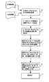
図2は、本発明の態様に係る、立体のペアの少なくとも2つの2次元(2D)画像のマーク付けの例示的な方法のフローダイアグラムである。はじめに、ステップ202で、後処理装置102は、たとえば左目の画像と右目の画像をもつ立体画像といった少なくとも2つの2次元(2D)画像を取得する。後処理装置102は、コンピュータ読み取り可能なフォーマットでデジタルマスタ画像ファイルを取得することで、少なくとも2つの2次元画像を取得する。デジタルビデオファイルは、デジタルカメラで動画像の時間系列を捕捉することで取得される場合がある。代替的に、ビデオ系列は、従来のフィルムタイプのカメラにより捕捉される。このシナリオでは、フィルムは、スキャニング装置103を介して走査される。 FIG. 2 is a flow diagram of an exemplary method for marking at least two two-dimensional (2D) images of a stereo pair in accordance with an aspect of the present invention. First, in
フィルムがスキャンされるか又は既にデジタルフォーマットにあるかに関わらず、フィルムのデジタルファイルは、たとえばフレーム番号、フィルムの開始からの時間等のフレームの位置に関する示唆又は情報を含むことが理解される。デジタル画像ファイルのそれぞれのフレームは、たとえばI1,I2,...,Inといった1つの画像を含む。 Regardless of whether the film is scanned or already in digital format, it is understood that the digital file of the film contains suggestions or information regarding the position of the frame, such as the frame number, time from the start of the film, and the like. Each frame of the digital image file is, for example, I1, I2,. . . , In, one image.
図3を参照して、左側の画像302及び右側の画像304が示される。図3で示される例では、ここでは、簡単さのために“No”のテキストメッセージである、テキストメッセージで画像がマーク付けされる。3D映画の遷移の環境では、メッセージは、「3次元映画開始“3D Movie Start”」、「メガネ装着“Put On Glasses”」等と読まれる。 With reference to FIG. 3, a
図2及び図3を参照して、ステップ204では、マークは第一又は左画像に付けられ、この場合、マークは、少なくとも2つの色を含む。左側画像302では、画像の背景306は、黒であるように選択され、テキスト308は、白であるように選択される。ステップ206では、第二の、同じマークは、第二の又は右側の画像304に付けられる。第二の又は右側の画像304では、画像の背景310は、たとえば画像302の背景の相補的な色である白であるように選択され、テキスト312は、たとえば画像302のテキストの相補的な色である黒であるように選択される。この例では、マークが画像全体であると理解される。相補的な色のマークは、ほんの1例であり、1つのマークとなる2以上の色の組み合わせであり、1つの色に結合されるマークの全ての画素は、本発明の教示に従う。マーク又はテキストは、幾つかの連続するフレームに付けられるか、たとえばある映画又は動画の開始といった予め決定された期間に付けられる場合がある。なお、上述されたように、第一の画像において少なくとも2つの色を有するマークを使用すること、及び第二の画像において少なくとも2つの相補的な色を有するマークを使用することは、マークがテキストであるときに好ましいが、第一の画像において唯一の色を有するマークを使用すること、及び第二の画像において相補的な色を有するマークを使用することは、当業者により理解されるように本発明の範囲にある。唯一の色を有するマーク(すなわち第一の色及び相補的な色)は、たとえば限定されるものではないが、マークがオブジェクト、ロゴ、幾何学的形状等であるときに使用される。 2 and 3, in
ステップ208では、マークアップされた立体映画は、視聴者に再生又は表示される。画像314は、特殊な3Dメガネを装着した視聴者が見たときの結果的な画像を例示し、画像316は、特殊な3Dメガネを装着していない視聴者が見たときの結果的な画像を例示する。画像316に示されるように、マーク又はメッセージは、左画像302と右画像304との間の奥行きのために、視聴者が3Dメガネを装着し始める前に視聴者に提示される。画像314では、画像302及び画像304の両者の色は、メタメリックであるように選択されており、且つ画像は、メガネの使用と協調するので、マークの色は、1つの色及びマーク、すなわちテキストメッセージを形成するように結合し、もはや視聴者に見えない。この例では、画像314はグレイに見える。 In
図3(a)に関して記載される例は単色、すなわち黒及び白の立体情報を採用しているが、図3(b)に示されるように、有色の立体情報が採用される場合がある。色が記載されるが、図3(b)の画像は、グレイスケール、黒及び白で表示され、色は、参照符号により図3(b)で記載及び表される。この例では、画像320、画像の背景324は、赤であるように選択され、テキスト326が緑であるように選択される。第二の又は右画像322では、画像の背景328は、緑、すなわち画像320の背景のメタメリックな色に選択され、テキスト330は、赤、すなわち画像320のテキストのメタメリックな色に選択される。画像334で示されるように、マーク又はテキストは、3Dメガネを使用することなしに見る事ができ、しかし、3Dメガネを使用すると、画像332は、無地であるように見えるか又はマークを有さない。この例では、画像332は、赤及び緑の色の結合のために、視聴者に黄色に見える。 The example described with respect to FIG. 3A employs monochromatic information, that is, black and white stereo information, but as shown in FIG. 3B, colored stereo information may be employed. Although the colors are described, the image of FIG. 3 (b) is displayed in gray scale, black and white, and the colors are described and represented in FIG. 3 (b) by reference numerals. In this example,
更なる実施の形態では、本発明のシステム及び方法は、反海賊行為の目的であるフィルムにマーク付けするものである。ある映画の海賊行為又は複製では、複製者は、3Dコンテンツが実行されている間、特別のフィルタをカムコーダの前に配置する。言い換えれば、カムコーダは、フィルムの2Dバージョンとして唯一の画像を捕捉している。この場合、カムコーダは1つのアパーチャのみを有するため、フィルムに付加されるマーク又はメッセージが画像に現れ、左画像と右画像の統合は、不可能である。 In a further embodiment, the system and method of the present invention marks a film that is the object of anti-piracy. In a movie piracy or duplication, the duplicator places a special filter in front of the camcorder while the 3D content is being executed. In other words, the camcorder captures a single image as a 2D version of the film. In this case, since the camcorder has only one aperture, a mark or message added to the film appears in the image, and integration of the left and right images is not possible.
反海賊行為のため、マーク又は幾つかのマークは、フィルムの開始のみでなく、複製されたバージョンの品質を低下させるためにフィルムを通して付加されるべきであることが理解されるべきである。マークは、警告メッセージの形式を取るか、又は適切な視聴の障害となるオブジェクトに関するマークであることを更に理解されたい。 It should be understood that because of anti-piracy, marks or some marks should be added through the film not only at the beginning of the film, but also to reduce the quality of the duplicated version. It should be further understood that the mark is in the form of a warning message or is related to an object that interferes with proper viewing.
図4及び図5を参照して、後処理装置102は、上述された左目の画像と右目の画像とをもつ立体画像のペアといった少なくとも2つの2次元(2D)画像502,504を取得する(ステップ402)。この実施の形態では、マークは、幾つかの他のコンテンツを有する画像に付加される可能性が最も高い。したがって、コンテンツを不明瞭にしないようにマークについて適切な位置が決定される必要がある。さらに、変化するシーン及びショットのため、マークは、フィルムを通して移動される必要がある可能性が高い。 4 and 5, the post-processing device 102 acquires at least two two-dimensional (2D)
ステップ406では、シーケンスアナライザ118は、マーク付けされるシーケンスの複数の連続するフレームを決定する。連続するフレームは、単一のショット又はシーン或いは共通のオブジェクトを有する複数のフレームからのフレームである場合がある。随意に、オブジェクトセグメンタ120は、立体のペアの少なくとも1つの画像からのオブジェクトを分割する。このオブジェクトは、シーンの連続するフレームの数を決定するため、シーケンスアナライザ118により使用される。次いで、オブジェクトは、特定のシーンのマークのための位置として選択される。このように、マークの色を選択するためにオブジェクトの色が使用され、従って再生の間に視聴されたとき、マークは視聴者に見えない。 In
ステップ408では、カラーアナライザ116は、マーク付けされる画像の位置の色又はマークされるオブジェクトの色を決定する。たとえば図5の画像502及び504では、空506は青であり、太陽508は黄色であり、草510は緑であることが決定される。この例では、マーク512は、画像の草の部分に配置されるように選択される。マーク512の位置の選択は手動的であるか、又は分割されているオブジェクトの色に基づいてポストプロセッシング装置102により自動的に決定される場合がある。 In
ステップ410で、結合されたときに、マークの位置の色を生成する少なくとも2つの色が選択される。記載される例では、マーク512は緑の上に位置されるので、選択される2つの色は、青及び黄色である。2を超える色を選択することができ、マークの位置の色を生成するために結合することができることを理解されたい。1実施の形態では、カラーアナライザ116は、マークの少なくとも2つの色を決定するため、マークの位置の色をスペクトル的に分割する。 At
つぎに、ステップ412において、マーク512は、第一の又は左画像514に付加される。マーク512は、任意の形式を取ることができ、それぞれ色を有する幾つかのコンポーネント又は部分を有する。簡単さのため、マーク512は、それぞれ色を有する2つの部分に分割される。ここで、マーク512は、青に着色される第一の部分518を含む。マーク512は、黄色に着色される第二の部分520を含む。ステップ414では、第二の同じマーク522は、マーク512が画像514に付加されたのと実質的に同じ位置において第二の又は右画像516に付加される。マーク522は、マーク512の第一及び第二の部分の色の異なる色(たとえば反対の色)で構築される。ここで、マーク522は、黄色である第一の部分524と青である第二の部分526とを含む。マークは、シーケンスのそれぞれのフレームに付加されるか、又はシーケンスの複数の連続するフレームの一部に付加される場合があることを理解されたい。 Next, in
マークアップされた画像は、たとえば記憶装置124に記憶され、3D再生のために読み出される場合がある(416)。さらに、動画像又はビデオクリップの全ての画像は、動画像又はクリップのマークアップされた立体のバージョンを表す1つのデジタルファイル130で記憶することができる。デジタルファイル130は、たとえばフィルムプリンタ128を介したオリジナルフィルム126の立体のバージョンを印刷するため、後の読み出しのために記憶装置124で記憶される場合がある。 The marked-up image may be stored, for example, in
3D再生の間、ステップ416において、3Dメガネを装着している視聴者は、画像514及び516の統合として3D画像528を見る。この統合において、第一のマーク512及び第二のマーク522はオーバラップし、それぞれの部分の色は、統合されたマークの全ての画素について、目に見える1つの色、ここでは緑を生成するために結合される。この例では、マーク512の第一の青の部分518は、マーク522の第一の黄色の部分524と結合し、マーク512の第二の黄色の部分520は、マーク522の第二の青の部分526と結合する。3Dメガネで視聴したとき、結果として得られる画像528は、マークを表示せず、すなわち3D画像528の視聴者は、結合又は統合されたマークを見る事ができない。しかし、あるフィルタをもつカムコーダを使用して映画が複製された場合、複製プロセスの間に、たとえば左画像である画像のうちの唯一の画像が記録され、したがって、再生の間に、マーク512は、目に見る事ができ、複製されたフィルムの品質を低下する。1を超えるマークは、任意の画像に付加することができ、したがって海賊行為となる複製において目に見える複数のマークを形成して、複製されるフィルムの品質を低下させることができることを理解されたい。マークは、フィルムのそれぞれのフレームに配置され、複製されたフィルムの見易さの品質を低下させることができる。 During 3D playback, at
本発明の教示を盛り込んだ実施の形態が本明細書において詳細に図示及び記載されたが、当業者であれば、これらの教示を盛り込んだ多数の他の変形された実施の形態を容易に創作することができる。(例示するものであって限定するものではない)色でフィルムにマーク付けするシステム及び方法の好適な実施の形態が記載されたが、変更及び変形は、先の教示に照らして当業者によりなされる。特許請求の範囲により概説される開示の範囲にある特定の実施の形態において、変形が行われる場合があることを理解されたい。 While embodiments that incorporate the teachings of the present invention have been shown and described in detail herein, those of ordinary skill in the art can easily create numerous other modified embodiments that incorporate these teachings. can do. While preferred embodiments of systems and methods for marking films with color (illustrated and not limiting) have been described, modifications and variations will occur to those skilled in the art in light of the foregoing teachings. The It should be understood that variations may be made in the specific embodiments that fall within the scope of the disclosure outlined by the claims.
Claims (16)
Translated fromJapanese前記第一の画像における予め決定された位置の色を決定するステップと、
第一の色を有する第一のマークを前記第一の画像における前記予め決定された位置に付加するステップと、
前記第一のマークの第一の色とは異なる第二の色を有する第二のマークを、前記第二の画像の、前記第一の画像における前記予め決定された位置と実質的に同じ位置に付加するステップと、
前記第一のマークの前記第一の色と前記第二のマークの前記第二の色とを、前記第一の画像における前記予め決定された位置の色のメタメリックな色として選択するステップとを含み、
3次元モードで見たときに、前記第一のマークと前記第二のマークは、1つの色からなる1つのマークに結合される、
ことを特徴とするマーキング方法。Obtaining a stereoscopic image including a first image and a second image;
Determining a color at a predetermined position in the first image;
Adding a first mark having a first color to thepredetermined position in the first image;
The second mark, said second image,said predetermined position and substantially the same location in the first image having a different second color and the first color of the first mark and the step of addingto,
Selecting the first color of the first mark and the second color of the second mark as a metameric color of the predetermined position in the first image; Including
Whenviewed in athree- dimensional mode, the first mark and the second mark are combined into one mark of one color.
A marking method characterized by that.
請求項1記載の方法。The first mark and the second mark are at least one of a text message, an object, and a logo.
The method of claim 1.
前記第一のマークを付加するステップ及び前記第二のマークを付加するステップは、前記第一のマーク及び前記第二のマークを前記系列のそれぞれのフレームに付加するステップを含む、
請求項1記載の方法。The stereoscopic image is a stereoscopic scene including a series of consecutive frames of the first image and the second image;
Adding the first mark and adding the second mark include adding the first mark and the second mark to each frame of the sequence;
The method of claim 1.
前記第一のマークを付加するステップ及び前記第二のマークを付加するステップは、前記系列の複数の連続するフレームの一部に前記第一のマーク及び前記第二のマークを付加するステップを含む、
請求項1記載の方法。The stereoscopic image is a stereoscopic scene including a series of consecutive frames of the first image and the second image;
The step of adding the first mark and the step of adding the second mark include adding the first mark and the second mark to a part of a plurality of consecutive frames of the series. ,
The method of claim 1.
請求項1記載の方法。The first image and the second image include a left-eye image and a right-eye image of the stereoscopic image,
The method of claim 1.
前記第一のマーク及び前記第二のマークを前記オブジェクトに付加するステップと、
を更に含む請求項1記載の方法。Dividing an object from the first image and the second image;
Adding the first mark and the second mark to the object;
The method of claim 1 further comprising:
請求項1記載の方法。The colors of the first mark and the second mark are monochromatic or colored,
The method of claim 1.
前記第一の画像における予め決定された位置の色を決定し、前記第一の画像における前記予め決定された位置に第一の色を有する第一のマークを付加し、前記第二の画像の、前記第一の画像における前記予め決定された位置と実質的に同じ位置に付加するマーキングモジュールとを含み、
前記第一のマークの前記第一の色と前記第二のマークの前記第二の色とは、前記第一の画像における前記予め決定された位置の色のメタメリックな色として選択され、
3次元モードで見たときに、前記第一のマークと前記第二のマークは、1つの色からなる1つのマークに結合される、
ことを特徴とするマーキングシステム。Means for obtaining a stereoscopic image including a first image and a second image;
Determining a color of a predetermined position in the first image, adding a first mark having a first color to thepredetermined position in the first image, and , and a marking module to be added tothe predetermined position and substantially the same location in the first image,
The first color of the first mark and the second color of the second mark are selected as a metameric color of the color at the predetermined position in the first image,
Whenviewed in a three-dimensional mode, the first mark and the second mark are combined into one mark of one color.
Marking system characterized by that.
請求項8記載のシステム。The first mark and the second mark are at least one of a text message, an object, and a logo.
The system of claim8 .
マークが付加される前記系列の複数の連続するフレームを選択するシーケンスアナライザを更に有する、
請求項8記載のシステム。The stereoscopic image is a stereoscopic scene including a series of consecutive frames of the first image and the second image;
A sequence analyzer for selecting a plurality of consecutive frames of the sequence to which a mark is added;
The system of claim8 .
請求項10記載のシステム。The marking module adds the first mark and the second mark to each frame of the selected sequence;
The system of claim10 .
請求項10記載のシステム。The marking module adds the first mark and the second mark to a part of a plurality of consecutive frames of the series;
The system of claim10 .
請求項8記載のシステム。The first image and the second image include a left-eye image and a right-eye image of the stereoscopic image,
The system of claim8 .
前記マーキングモジュールは、前記第一及び第二のマークを前記第一及び第二の画像に付加する、
請求項8記載のシステム。An object dividing means for dividing the object from the first image;
The marking module adds the first and second marks to the first and second images;
The system of claim8 .
請求項8記載のシステム。The colors of the first mark and the second mark are monochromatic or colored,
The system of claim8 .
Applications Claiming Priority (1)
| Application Number | Priority Date | Filing Date | Title |
|---|---|---|---|
| PCT/US2008/007508WO2009151424A1 (en) | 2008-06-13 | 2008-06-13 | System and method for marking a stereoscopic film |
Publications (2)
| Publication Number | Publication Date |
|---|---|
| JP2011525324A JP2011525324A (en) | 2011-09-15 |
| JP5383798B2true JP5383798B2 (en) | 2014-01-08 |
Family
ID=40344886
Family Applications (1)
| Application Number | Title | Priority Date | Filing Date |
|---|---|---|---|
| JP2011513465AExpired - Fee RelatedJP5383798B2 (en) | 2008-06-13 | 2008-06-13 | System and method for marking three-dimensional film |
Country Status (6)
| Country | Link |
|---|---|
| US (1) | US8520934B2 (en) |
| EP (1) | EP2292017A1 (en) |
| JP (1) | JP5383798B2 (en) |
| CN (1) | CN102067611B (en) |
| CA (1) | CA2727397C (en) |
| WO (1) | WO2009151424A1 (en) |
Families Citing this family (12)
| Publication number | Priority date | Publication date | Assignee | Title |
|---|---|---|---|---|
| US20110170069A1 (en)* | 2010-01-11 | 2011-07-14 | David Lee Lund | Stereoscopic film marking and method of use |
| CN102754122B (en)* | 2010-02-08 | 2015-07-08 | 汤姆森特许公司 | Method and system for forensic marking of stereoscopic 3d content media |
| KR20120020477A (en)* | 2010-08-30 | 2012-03-08 | 삼성전자주식회사 | Three dimensional image display apparatus and driving method thereof |
| CN103581639A (en)* | 2012-07-23 | 2014-02-12 | 信泰光学(深圳)有限公司 | Method and system for processing 3D images |
| US9251760B2 (en)* | 2013-07-02 | 2016-02-02 | Cisco Technology, Inc. | Copy protection from capture devices for photos and videos |
| US10303242B2 (en) | 2014-01-06 | 2019-05-28 | Avegant Corp. | Media chair apparatus, system, and method |
| US10409079B2 (en) | 2014-01-06 | 2019-09-10 | Avegant Corp. | Apparatus, system, and method for displaying an image using a plate |
| CN104702939B (en) | 2015-03-17 | 2017-09-15 | 京东方科技集团股份有限公司 | Image processing system, method, the method for determining position and display system |
| US9823474B2 (en) | 2015-04-02 | 2017-11-21 | Avegant Corp. | System, apparatus, and method for displaying an image with a wider field of view |
| US9995857B2 (en) | 2015-04-03 | 2018-06-12 | Avegant Corp. | System, apparatus, and method for displaying an image using focal modulation |
| US20150237327A1 (en)* | 2015-04-30 | 2015-08-20 | 3-D XRay Technologies, L.L.C. | Process for creating a three dimensional x-ray image using a single x-ray emitter |
| CN115601329A (en)* | 2022-10-19 | 2023-01-13 | 深圳华大智造云影医疗科技有限公司(Cn) | Image processing method and device, electronic device and storage medium |
Family Cites Families (17)
| Publication number | Priority date | Publication date | Assignee | Title |
|---|---|---|---|---|
| JPH08205198A (en)* | 1995-01-26 | 1996-08-09 | Sony Corp | Image pickup device |
| US6550949B1 (en)* | 1996-06-13 | 2003-04-22 | Gentex Corporation | Systems and components for enhancing rear vision from a vehicle |
| DE60014420T2 (en)* | 1999-11-26 | 2005-10-13 | Sanyo Electric Co., Ltd., Moriguchi | METHOD FOR 2D / 3D VIDEO CONVERSION |
| US20030123663A1 (en) | 2001-12-27 | 2003-07-03 | Epstein Michael A. | Method and apparatus for preventing unauthorized copying of screen images |
| JP3983573B2 (en)* | 2002-03-06 | 2007-09-26 | 富士重工業株式会社 | Stereo image characteristic inspection system |
| US7130488B2 (en)* | 2002-10-09 | 2006-10-31 | Xerox Corporation | Systems for spectral multiplexing of source images including a textured source image to provide a composite image, for rendering the composite image, and for spectral demultiplexing of the composite image |
| US7136522B2 (en)* | 2002-10-09 | 2006-11-14 | Xerox Corporation | Systems for spectral multiplexing of source images to provide a composite image, for rendering the composite image, and for spectral demultiplexing of the composite image to animate recovered source images |
| US7155068B2 (en)* | 2002-10-09 | 2006-12-26 | Xerox Corporation | Systems for spectral multiplexing of source images to provide a composite image, for rendering the composite image, and for spectral demultiplexing the composite image, which achieve increased dynamic range in a recovered source image |
| JP4490074B2 (en)* | 2003-04-17 | 2010-06-23 | ソニー株式会社 | Stereoscopic image processing apparatus, stereoscopic image display apparatus, stereoscopic image providing method, and stereoscopic image processing system |
| JP4532982B2 (en)* | 2004-05-14 | 2010-08-25 | キヤノン株式会社 | Arrangement information estimation method and information processing apparatus |
| JP4630150B2 (en)* | 2005-07-26 | 2011-02-09 | シャープ株式会社 | Stereoscopic image recording apparatus and program |
| JP4630149B2 (en) | 2005-07-26 | 2011-02-09 | シャープ株式会社 | Image processing device |
| JP5029608B2 (en)* | 2006-08-02 | 2012-09-19 | 日本電気株式会社 | Image processing apparatus, display apparatus, and image display system |
| CN101153961A (en)* | 2006-09-29 | 2008-04-02 | 精工爱普生株式会社 | Display device, image processing method, and electronic device |
| US20100060723A1 (en)* | 2006-11-08 | 2010-03-11 | Nec Corporation | Display system |
| WO2008152932A1 (en)* | 2007-06-13 | 2008-12-18 | Nec Corporation | Image display device, image display method and image display program |
| CN101358936B (en)* | 2007-08-02 | 2011-03-16 | 同方威视技术股份有限公司 | Method and system for discriminating material by double-perspective multi energy transmission image |
- 2008
- 2008-06-13CNCN200880129802.5Apatent/CN102067611B/ennot_activeExpired - Fee Related
- 2008-06-13USUS12/737,137patent/US8520934B2/ennot_activeExpired - Fee Related
- 2008-06-13CACA2727397Apatent/CA2727397C/ennot_activeExpired - Fee Related
- 2008-06-13JPJP2011513465Apatent/JP5383798B2/ennot_activeExpired - Fee Related
- 2008-06-13WOPCT/US2008/007508patent/WO2009151424A1/enactiveApplication Filing
- 2008-06-13EPEP08779654Apatent/EP2292017A1/ennot_activeWithdrawn
Also Published As
| Publication number | Publication date |
|---|---|
| CA2727397C (en) | 2016-02-16 |
| WO2009151424A1 (en) | 2009-12-17 |
| CN102067611B (en) | 2015-05-20 |
| US20110085727A1 (en) | 2011-04-14 |
| JP2011525324A (en) | 2011-09-15 |
| EP2292017A1 (en) | 2011-03-09 |
| CA2727397A1 (en) | 2009-12-17 |
| CN102067611A (en) | 2011-05-18 |
| US8520934B2 (en) | 2013-08-27 |
Similar Documents
| Publication | Publication Date | Title |
|---|---|---|
| JP5383798B2 (en) | System and method for marking three-dimensional film | |
| US8358332B2 (en) | Generation of three-dimensional movies with improved depth control | |
| US9167226B2 (en) | Selecting viewpoints for generating additional views in 3D video | |
| JP5132690B2 (en) | System and method for synthesizing text with 3D content | |
| RU2552137C2 (en) | Entry points for fast 3d trick play | |
| EP2432229A2 (en) | Object tracking and highlighting in stereoscopic images | |
| JP5851625B2 (en) | Stereoscopic video processing apparatus, stereoscopic video processing method, and stereoscopic video processing program | |
| CN102754122B (en) | Method and system for forensic marking of stereoscopic 3d content media | |
| JP2010531102A (en) | Method and apparatus for generating and displaying stereoscopic image with color filter | |
| CN110505471A (en) | A head-mounted display device and its screen acquisition method and device | |
| US7660472B2 (en) | System and method for managing stereoscopic viewing | |
| JP2011124941A (en) | Apparatus and method for producing three-dimensional video | |
| JP2009500963A (en) | System and method for capturing visual and non-visual data for multi-dimensional video display | |
| TW201249175A (en) | Method and system for utilizing depth information as an enhancement layer | |
| JP5861114B2 (en) | Image processing apparatus and image processing method | |
| KR101430985B1 (en) | System and Method on Providing Multi-Dimensional Content | |
| CN101268685B (en) | System, device and method for capturing and projecting picture images for multi-dimensional display | |
| CN101292516A (en) | Systems and methods for capturing picture data | |
| JP4712875B2 (en) | System, apparatus and method for capturing and projecting visual images for multi-dimensional displays | |
| KR100480007B1 (en) | System for producing and displaying three dimensional image and method for the same | |
| JP5604173B2 (en) | Playback device, display device, recording device, and storage medium | |
| JP2013090170A (en) | Stereoscopic image reproduction device | |
| JP2008259155A (en) | Z-value synthesis material creating apparatus using digital still camera |
Legal Events
| Date | Code | Title | Description |
|---|---|---|---|
| A131 | Notification of reasons for refusal | Free format text:JAPANESE INTERMEDIATE CODE: A131 Effective date:20121016 | |
| A521 | Request for written amendment filed | Free format text:JAPANESE INTERMEDIATE CODE: A523 Effective date:20130111 | |
| A131 | Notification of reasons for refusal | Free format text:JAPANESE INTERMEDIATE CODE: A131 Effective date:20130205 | |
| TRDD | Decision of grant or rejection written | ||
| A01 | Written decision to grant a patent or to grant a registration (utility model) | Free format text:JAPANESE INTERMEDIATE CODE: A01 Effective date:20130917 | |
| A61 | First payment of annual fees (during grant procedure) | Free format text:JAPANESE INTERMEDIATE CODE: A61 Effective date:20131001 | |
| R150 | Certificate of patent or registration of utility model | Free format text:JAPANESE INTERMEDIATE CODE: R150 | |
| LAPS | Cancellation because of no payment of annual fees |