JP5379497B2 - Rotation transmission equipment - Google Patents
Rotation transmission equipmentDownload PDFInfo
- Publication number
- JP5379497B2 JP5379497B2JP2009015945AJP2009015945AJP5379497B2JP 5379497 B2JP5379497 B2JP 5379497B2JP 2009015945 AJP2009015945 AJP 2009015945AJP 2009015945 AJP2009015945 AJP 2009015945AJP 5379497 B2JP5379497 B2JP 5379497B2
- Authority
- JP
- Japan
- Prior art keywords
- gear
- gear set
- output
- input
- carrier
- Prior art date
- Legal status (The legal status is an assumption and is not a legal conclusion. Google has not performed a legal analysis and makes no representation as to the accuracy of the status listed.)
- Active
Links
Images


Landscapes
- Structure Of Transmissions (AREA)
Abstract
Description
Translated fromJapanese本発明は、回転伝達機器、殊に駆動源からの回転駆動を変速して出力軸に出力する回転伝達機器に関するものである。 The present invention relates to a rotation transmission device, and more particularly to a rotation transmission device that shifts rotational drive from a drive source and outputs it to an output shaft.
従来からインパクト回転工具やドリルドライバー等の電動工具には減速機構を備えており、例えば、特許文献1や特許文献2のように、少なくとも二つの変速歯車組を有して、該変速歯車組の減速・非減速状態を切り替えることで3速に変速可能としたものがある。 Conventionally, an electric power tool such as an impact rotary tool or a drill driver has a reduction mechanism, and for example, as in
しかしながら、特許文献1や特許文献2では変速歯車組を回転軸に相対回転不能とすることで減速比を1として非減速状態としていた。そのため、変速歯車組の有する慣性モーメントが大きくなり、回転初期に必要なエネルギーが多くなっていた。 However, in
また、入力軸から出力軸までに回転駆動を伝達する部材が多いため、歯車の噛み合いによる伝達ロスが大きくなり、伝達効率の低下を生じていた。 Further, since there are many members that transmit the rotational drive from the input shaft to the output shaft, the transmission loss due to the meshing of the gears is increased, resulting in a decrease in transmission efficiency.
そこで、本発明は上記問題に鑑みて発明したものであり、非減速状態の変速歯車組を出力軸へ回転駆動を伝達する歯車組として使用するか否かの切替を行う切替手段を備えることで、減速比の小さいモードで使用する際に、回転駆動が伝達される歯車組を減らして、慣性モーメント及び伝達ロスを低減させて、伝達効率の向上した回転伝達機器を提供することを課題とした。 Accordingly, the present invention has been invented in view of the above problems, and includes a switching means for switching whether or not to use a non-decelerated transmission gear set as a gear set for transmitting rotational drive to an output shaft. It is an object of the present invention to provide a rotation transmission device with improved transmission efficiency by reducing the gear set to which rotation drive is transmitted and reducing the moment of inertia and transmission loss when used in a mode with a small reduction ratio. .
上記課題を解決するために、本発明の回転伝達機器は、駆動源から回転駆動が入力される入力軸71と、入力軸71に入力された回転駆動を変速する多段式変速機構部と、変速された回転駆動を出力する出力軸72と、からなる回転伝達機器であって、上記多段式変速機構部は、入力軸71から回転駆動を受ける入力歯車組と、出力軸72に回転駆動を出力する出力歯車組と、上記入力歯車組及び出力歯車組の間に少なくとも一つ以上配置された中間歯車組と、を有すると共に、上記歯車組の少なくとも一つに対して入力軸71から入力された回転駆動を変速する変速状態及び上記回転駆動を変速しない非変速状態を切り替える歯車切替手段と、上記多段式変速機構部内の入力軸71から上記出力軸72へ回転駆動が伝達される伝達経路から上記歯車組の少なくとも一つを外す非使用状態及び上記伝達経路に加える使用状態を切り替える経路切替手段と、を備えており、上記二つの切替手段の各状態の切替を組み合わせることで入力軸71から入力された回転駆動を少なくとも三つの異なる速度モードに変速して出力軸72に出力し、上記経路切替手段によって使用・非使用状態が切り替わる少なくとも一つの歯車組は、太陽歯車と、内歯歯車と、遊星歯車と、を有した遊星減速歯車組であり、上記経路切替手段の少なくとも一つが、上記遊星減速歯車組とこの遊星減速歯車組より入力側の歯車組との間に配置されこの入力側の歯車組から上記太陽歯車に回転駆動を伝達する伝達キャリアであり、該伝達キャリアが上記入力側の歯車組に対して上記太陽歯車を伴って軸方向に沿ってスライド移動自在であると共に、該スライド移動により上記太陽歯車が上記遊星歯車に係脱自在であり、上記伝達キャリア52は上記太陽歯車の離脱時に上記遊星減速歯車組を非使用状態にするものであることを特徴としている。
In order to solve the above problems, a rotation transmission device according to the present invention includes an
このような構成としたことで、上記三つの速度モードのうち、少なくとも一つが伝達経路から少なくとも一つの歯車組を外して回転駆動を伝達するものとなる。 With such a configuration, at least one of the three speed modes transmits the rotational drive by removing at least one gear set from the transmission path.
また、請求項2に係る発明は、多段式変速機構部は歯車切替手段によって変速・非変速状態が切り替わる歯車組を経路切替手段より入力軸71側に配置したものであり、上記変速・非変速状態の切り替わる歯車組が非使用状態にならない歯車組としたことを特徴としている。 According to a second aspect of the present invention, the multi-stage speed change mechanism is configured such that a gear set that is switched between a speed change state and a non-speed change state by the gear change means is arranged on the
また、請求項3に係る発明は、歯車切替手段によって変速・非変速状態が切り替わる歯車組を経路切替手段より出力軸72側に配置したものであり、上記変速・非変速状態の切り替わる歯車組は上記経路切替手段によって非使用状態になる歯車組の一つとしたことを特徴としている。 According to a third aspect of the present invention, a gear set that is switched between a speed change and a non-shift state by the gear switching means is arranged on the
また、請求項4に係る発明は、経路切替手段を少なくとも二つ以上備えており、上記経路切替手段の一つが歯車切替手段と連動しており、歯車切替手段が歯車組を非変速状態に切り換えると、該歯車組を非使用状態に切り換えるものとしたことを特徴としている。The invention according to
また、請求項5に係る発明は、出力軸72に所定のトルクが加わった際に上記出力軸72への回転駆動の伝達を遮断するクラッチ機構73を前記出力歯車組が備えており、上記出力歯車組が非使用状態にならない歯車組としたことを特徴としている。 According to a fifth aspect of the present invention, the output gear set includes a
また、請求項6に係る発明は、中間歯車組の少なくとも一つと、出力歯車組と、が、太陽歯車と、内歯歯車と、遊星歯車と、を夫々有した遊星減速歯車組であって、伝達キャリア52は上記中間歯車組の太陽歯車を伴って軸方向に沿ってスライド移動自在であると共に、該スライド移動により上記中間歯車組の太陽歯車は遊星歯車に係脱自在であり、該伝達キャリア52は該太陽歯車の離脱時に出力歯車組の太陽歯車に相対回転不能で係合する直結係合部を備えており、上記直結係合部が上記出力歯車組の太陽歯車に係合することで上記伝達キャリア52に入力された回転駆動を直接出力歯車組に伝達して上記遊星減速歯車組である中間歯車組及び上記遊星減速歯車組である中間歯車組と出力歯車組との間に配置された歯車組を全て非使用状態にするものとしたことを特徴としている。The invention according to claim 6 is a planetary reduction gear set in which at least one of the intermediate gear sets and the output gear set each have a sun gear, an internal gear, and a planetary gear, withtransfer our
また、請求項7に係る発明は、入力歯車組は出力軸72側に変速した回転駆動を出力する出力キャリアを備えたものであり、且つ出力歯車組は入力側に回転駆動が入力される入力キャリアを備えたものであって、経路切替手段の他の一つは、軸方向に沿ってスライド移動自在で且つ該スライド移動によって上記出力キャリア及び上記入力キャリアに同時に係合すると共に上記係合により上記二つのキャリアを一体回転可能に連結する連結部材61であり、上記二つのキャリアの連結により中間歯車組を全て非使用状態にするものとしたことを特徴としている。According to a seventh aspect of the present invention, the input gear set includes an output carrier that outputs a rotational drive shifted to the
また、請求項8に係る発明は、出力軸72に所定のトルクが加わった際に上記出力軸72への回転駆動の伝達を遮断するクラッチ機構73を出力歯車組が備えており、上記出力歯車組が前記経路切替手段によって非使用状態になる歯車組の一つとしたことを特徴としている。 According to an eighth aspect of the present invention, the output gear set includes a
また、請求項9に係る発明は、中間歯車組は、太陽歯車と、内歯歯車と、遊星歯車と、を有した遊星減速歯車組であって、伝達キャリア52は上記中間歯車組の太陽歯車を伴って軸方向に沿ってスライド移動自在であると共に、該スライド移動により上記中間歯車組の太陽歯車は遊星歯車に係脱自在であり、該伝達キャリア52は該太陽歯車の離脱時に出力軸72に相対回転不能で係合する直結係合部を備えており、上記直結係合部が上記出力軸72に係合することで上記伝達キャリア52に入力された回転駆動を直接出力軸72に伝達して上記遊星減速歯車組及び上記遊星減速歯車組から出力軸72までの間に配置された歯車組を全て非使用状態にするものとしたことを特徴としている。In the invention, the intermediate gear set includes a sun gear, and internal gear, a planetary reduction gear set having a planetary gear, the sunheat our
また、請求項10に係る発明は、経路切替手段が少なくとも二つ以上の中間歯車組を非使用状態にするものとしたことを特徴としている。 The invention according to claim 10 is characterized in that the path switching means makes at least two or more intermediate gear sets non-use.
また、請求項11に係る発明は、出力歯車組は、太陽歯車と、内歯歯車と、遊星歯車と、を有した遊星減速歯車組であって、伝達キャリア52は上記出力歯車組の太陽歯車を伴って軸方向に沿ってスライド移動自在であると共に、該スライド移動により上記中間歯車組の太陽歯車は遊星歯車に係脱自在であり、該伝達キャリア52は該太陽歯車の離脱時に出力軸72に相対回転不能で係合する直結係合部を備えており、上記直結係合部が上記出力軸72に係合することで上記伝達キャリア52に入力された回転駆動を直接上記出力軸72に伝達して上記出力歯車組を非使用状態にするものとしたことを特徴としている。In the invention, the output gear set includes a sun gear, and internal gear, a planetary reduction gear set having a planetary gear, the sunheat our
上記のように、本発明の請求項1に係る回転伝達機器は、少なくとも一つの速度モードにおいて、伝達経路内から歯車組を外すため、該速度モードで回転駆動を伝達する歯車の数が減り、歯車の噛み合いによる伝達ロスを低減することができる。 As described above, in the rotation transmission device according to
そして、伝達ロスが減ったことで、出力軸への回転駆動の伝達効率が向上するため、出力軸のトルクを増大でき、駆動源の小型・軽量化ならびに低コスト化を行うことができる。 Since the transmission loss is reduced, the transmission efficiency of the rotational drive to the output shaft is improved, the torque of the output shaft can be increased, and the drive source can be reduced in size, weight and cost.
更に、小さい変速比で回転駆動を伝達する際に、変速に使用しない歯車組を伝達経路から外すことができるため、歯車組を非変速状態で用いたものより慣性モーメントを小さく抑えられ、回転初期に必要なエネルギーを少なくできる。 In addition, when transmitting rotational drive at a small gear ratio, gear sets that are not used for gear shifting can be removed from the transmission path, so that the moment of inertia can be suppressed to a smaller value than when gear sets are used in a non-shifting state. Less energy is needed.
また、請求項2に係る発明の効果は、歯車切替手段と経路切替手段とが状態の切替を行う歯車組が異なるため、多段式変速機構部の構成が複雑化することを防止できる。 The effect of the invention according to
また、請求項3に係る発明の効果は、変速比を最も小さくした際に、回転駆動を伝達する歯車の数を最も少なくでき、伝達ロスをより小さくすることができる。 Further, according to the third aspect of the invention, when the speed ratio is minimized, the number of gears that transmit the rotational drive can be minimized, and the transmission loss can be further reduced.
また、請求項4に係る発明の効果は、変速・非変速状態となる歯車組が非変速状態となった際に、非使用状態にできるため、非変速状態の歯車組を全てのモードで無くすことができ、伝導効率を向上することができる。Further, the effect of the invention according to
また、請求項5に係る発明の効果は、各切替手段によって歯車組の状態を切り替えても、クラッチ機構によるトルククラッチを常に有効な状態に維持することができる。 Further, the effect of the invention according to claim 5 is that the torque clutch by the clutch mechanism can always be maintained in an effective state even when the state of the gear set is switched by each switching means.
また、請求項6に係る発明の効果は、中間歯車組の太陽歯車から直接出力歯車組に回転駆動を伝達できて、遊星減速歯車組である中間歯車組を非減速状態で回転駆動を伝達するものに比べて伝達ロスを低減することができる。 In addition, the effect of the invention according to claim 6 is that the rotation drive can be transmitted directly from the sun gear of the intermediate gear set to the output gear set, and the rotation drive is transmitted to the intermediate gear set which is a planetary reduction gear set in a non-decelerated state. The transmission loss can be reduced compared to that.
また、請求項7に係る発明の効果は、変速比を小さくする際に、中間歯車組を全て伝達経路から外せるため、中間歯車組を非減速状態で回転駆動を伝達するものに比べて、伝達ロスを低減することができる。 Further, the effect of the invention according to claim 7 is that when the transmission gear ratio is reduced, all the intermediate gear sets can be removed from the transmission path. Loss can be reduced.
また、請求項8に係る発明の効果は、クラッチ機構を備えた出力歯車組が使用・非使用状態に切り替わるため、クラッチ機構の有効・無効の切替手段を別途設けること無く、経路切替手段による切替に連動して行うことができる。 Further, the effect of the invention according to claim 8 is that the output gear set provided with the clutch mechanism is switched to the use / non-use state, so that the switching by the path switching means is not provided without separately providing the valid / invalid switching means of the clutch mechanism. Can be performed in conjunction with
また、請求項9に係る発明の効果は、クラッチ機構の有効・無効が経路切替手段による中間歯車組の太陽歯車のスライド移動で行われるため、単純な構成でクラッチ機構の切替を行え、構造の複雑化を防止することができる。 Further, the effect of the invention according to claim 9 is that the clutch mechanism is enabled / disabled by sliding movement of the sun gear of the intermediate gear set by the path switching means, so that the clutch mechanism can be switched with a simple configuration, Complexity can be prevented.
また、請求項10に係る発明の効果は、より多くの歯車組を伝達経路から外せて、伝達ロスをより低減できるため、速い速度で回転した際に伝達効率をより向上することができる。 The effect of the invention according to claim 10 is that more gear sets can be removed from the transmission path and the transmission loss can be further reduced, so that the transmission efficiency can be further improved when rotating at a high speed.
また、請求項11に係る発明の効果は、変速の切替と、クラッチ機構の有効・無効と、を経路切替手段による出力歯車の太陽歯車のスライド移動で行え、構造の複雑化を抑制でき、簡易な構造にすることができる。 Further, according to the eleventh aspect of the present invention, it is possible to perform shift switching and valid / invalid of the clutch mechanism by sliding movement of the sun gear of the output gear by the path switching means, thereby suppressing the complexity of the structure and simplifying. Structure.
以下、図面に基づいて本発明の実施形態について説明する。 Hereinafter, embodiments of the present invention will be described with reference to the drawings.
本発明の回転伝達機器は、駆動源からの回転駆動が入力される入力軸71と、入力軸71からの回転駆動を変速する多段式変速機構部と、変速した回転駆動を出力する出力軸72と、を備えたものである。 The rotation transmission device according to the present invention includes an
そして、上記多段式変速機後部は、ケース81内に複数の変速段を備えており、各変速段を切替手段により変速・非変速状態に切り替えることで、入力軸71からの回転を複数の異なる速度に変速して出力軸72へ出力するものである。 The rear portion of the multi-stage transmission is provided with a plurality of shift stages in the
更に、回転伝達機器は回転工具に内蔵されて出力軸72がインパクト機構やドリルピット等に繋がったものであれば、駆動源からの回転駆動を減速して出力する減速手段として機能するものである。 Furthermore, if the rotation transmission device is built in the rotary tool and the
また、回転伝達機器を発電機等に内蔵すれば、駆動源からの回転駆動を加速して出力する加速手段として機能するが、以下の実施形態では回転伝達機器を減速手段として用いた例の説明のみを行う。なお、入力軸71及び出力軸72と、多段式変速機構部の各歯車の回転軸方向は同一となっており、回転軸に沿った方向を軸方向とすると共に、軸方向の入力軸71側を後方、出力軸72側を前方として説明する。 In addition, if the rotation transmission device is built in a generator or the like, it functions as an acceleration means for accelerating and outputting the rotation drive from the drive source. However, in the following embodiments, an example of using the rotation transmission device as the deceleration means Only do. In addition, the
実施形態1では、図1に示すように、上記多段式変速機構部が、入力軸71に繋がった入力段と、出力軸72に繋がった出力段と、入力段及び出力段の間に位置する中間段と、を備えたものであり、各段は夫々歯車組からなる減速機構となっている。詳しくは、各段は夫々、回転駆動が入力される太陽歯車と、太陽歯車より外周に位置したリング状の内歯歯車と、太陽歯車及び内歯歯車に噛み合う遊星歯車と、回転駆動を出力する遊星キャリアと、遊星キャリアに遊星歯車からの回転駆動を伝達する伝達軸と、からなる遊星減速機構である。なお、後方側から前方に向かって順に、入力段を第1歯車組1、中間段を第2歯車組2、出力段を第3歯車組3として、各組の歯車を、第1太陽歯車11、第2太陽歯車21、第3太陽歯車31等と記載することで夫々区別して説明する。 In the first embodiment, as shown in FIG. 1, the multi-stage transmission mechanism is located between an input stage connected to the
上記第1歯車組1は、入力軸71に固着された第1太陽歯車11と、ケース81の内壁に固定された第1内歯歯車12と、上記第1太陽歯車11及び第1内歯歯車12に噛み合う第1遊星歯車13と、からなるものである。そして、上記第1内歯歯車12がケース81に固定されているため、第1歯車組1は常に入力軸71からの回転を減速する減速段となっている。 The first gear set 1 includes a
また、第1遊星歯車13には第1伝達軸14が回転自在で挿通されており、第1伝達軸14により第1遊星キャリア15に減速された回転が伝達されている。そして、上記第1遊星キャリア15の前方側には第2歯車組2の第2太陽歯車21が形成されている。 A
上記第2歯車組2は、上記第2太陽歯車21と、軸方向に沿ってスライド移動可能な第2内歯歯車22と、上記第2太陽歯車21及び第2内歯歯車22に噛み合う第2遊星歯車23と、からなる減速状態と非減速状態とを切替可能な可変段である。そして、第2遊星歯車23には第2遊星キャリア25に回転駆動を伝達する第2伝達軸24が回転自在で挿通されている。 The second gear set 2 is engaged with the
また、第2内歯歯車22は軸方向に沿ってスライド移動することで、後方位置と、前方位置との二つの位置に切替可能となっている。そして、上記位置の切り替えは、ケース81外部に突出した切替操作部83を軸方向に沿って前方あるいは後方にスライド操作することにより第2内歯歯車22が前方あるいは後方にスライド移動するものである。 Moreover, the 2nd
詳しくは、図1(c)に示すように、第2内歯歯車22が前方位置にあると、第2遊星キャリア25に形成された外歯251に第2内歯歯車22が相対回転不能に噛み合っている。このとき、第2遊星歯車23と第2遊星キャリア25を第2内歯歯車22が同時に押さえて回転軸に相対回転不能で減速比を1にするため、第2歯車組2が非減速状態となっている。 Specifically, as shown in FIG. 1C, when the second
そして、図1(b)に示すように、切替操作部83を後方にスライドさせることで第2内歯歯車22が後方位置に移動して、第2内歯歯車22は第2遊星歯車23と噛み合ったまま、第2遊星キャリア25の外歯251との噛み合いを解く。 Then, as shown in FIG. 1B, the second
このとき、第2内歯歯車22の後方に延設された保持用係合部222がケース81の内壁に設けた保持部82に係合して、第2内歯歯車22がケース81に回転不能で保持される。 At this time, the
そして、第2内歯歯車22が回転不能となるため、中間段は減速段として機能する減速状態となる。更に、上記切替操作部83を前方にスライドさせることで、ケース81による保持が解かれ、図1(c)に示す非減速状態に戻る。 And since the 2nd
また、第2遊星キャリア25には前方に向けて駆動伝達ピン51が軸方向に沿って複数突設されており、該駆動伝達ピン51には伝達キャリア52が駆動伝達ピン51の軸に沿ってスライド移動可能で配置されている。 The
上記伝達キャリア52はスライド移動することで、後方位置と、前方位置と、の二つの位置に切替可能となっており、且つ上記いずれの位置にあっても第2遊星キャリア25からの回転駆動が駆動伝達ピン51を介して伝達されるものである。 The
そして、上記伝達キャリア52のスライド移動は、ケース81外部に突出したキャリア操作部84を前後にスライド操作することで、前方位置と後方位置との切替が行われるものとなっている。 The sliding movement of the
また、上記伝達キャリア52の前面には、経路切替手段である連結手段及び第3歯車組3の第3太陽歯車31を備えており、前述のスライド移動によって第3歯車組を使用・非使用状態に切替可能としたものとなっている。 Further, on the front surface of the
そして、上記第3歯車組3は、上記伝達キャリア52に一体で固着された第3太陽歯車31と、第3遊星歯車33と、ケース81の内壁に固定された第3内歯歯車32と、第3遊星歯車33に回転自在で挿通された第3伝達軸34と、第3伝達軸34から回転駆動が伝達される第3遊星キャリア35と、からなっている。 The third gear set 3 includes a
そして、第3遊星キャリア35の内周には出力軸72の後端が固着されており、一体で回転するものとなっている。 The rear end of the
更に、上記第3太陽歯車31は伝達キャリア52が前方位置にある状態で第3遊星歯車33に噛み合い、出力軸72への回転駆動を減速して伝達する使用状態となるものである。 Further, the
また、伝達キャリア52が前方位置から後方位置にスライド移動すると、第3太陽歯車31と第3遊星歯車33との噛み合いが解かれると共に、上記連結手段により伝達キャリア52と出力軸72が直結される。 When the
このとき、入力軸71からの回転駆動は第3歯車組3を経由しないで出力軸72へ伝達されるため、出力段である第3歯車組3は入力軸71から出力軸72への回転駆動の伝達経路から外れた非使用状態となっている。 At this time, since the rotational drive from the
そして、上記連結手段は、伝達キャリア52の回転中心に軸心を同じくし且つ伝達キャリア52に相対回転不能で後端を圧入された連結軸53と、上記連結軸53の前端に一体で形成された直結用係合部54と、出力軸72の内周面に設け直結用係合部54に係脱自在の被係合部55と、からなっている。 The connecting means is integrally formed at the front end of the connecting
更に、上記直結用係合部54と被係合部55との係脱は伝達キャリア52の前後のスライド移動によって行われるものである。 Further, the engagement / disengagement between the direct
詳しくは、図1(a)に示すように、伝達キャリア52が後方位置にあると、上記直結用係合部54と被係合部55とが係合して、伝達キャリア52と出力軸72とが一体で回転するものになり、第3歯車組3を介さずに回転駆動を伝達する第3歯車組3を非使用状態としたものになる。 Specifically, as shown in FIG. 1A, when the
そして、図1(b)に示すように、伝達キャリア52が前方位置に移動すると、上記直結用係合部54と被係合部55との係合が解かれると共に、第3太陽歯車31が第3遊星歯車33に噛み合い、第3歯車組3を使用状態に切り替える。 As shown in FIG. 1B, when the
また、第3歯車組3は前方側にクラッチ機構73を備えており、第3歯車組3が使用状態の際には回転伝達機器にトルククラッチがかかるものとなっている。詳しくは、第3内歯歯車32の出力側に設けたクラッチ山731と、上記クラッチ山731の間に配置された鋼球732と、上記鋼球732を後方へ付勢するクラッチばね733と、を有する従来と同様のクラッチ機構73である。 The third gear set 3 is provided with a
このように、第2歯車組2の減速・非減速状態の切替と、第3歯車組3の使用・非使用状態の切替を組み合わせることにより、図1(a)に示すような第1歯車組1及び第2歯車組2で回転を減速するモードと、図1(b)に示すような三つの歯車組全てで回転を減速するモードと、図1(c)に示すような第2歯車組2を非減速状態にして第1歯車組1及び第3歯車組3で回転を減速するモードと、特に図示しないが第2歯車組2を非減速状態にすると共に第3歯車組3を非使用状態にして第1歯車組1のみで回転を減速するモードと、の四つのモードに変速可能となっている。 As described above, the first gear set as shown in FIG. 1A is obtained by combining the switching between the deceleration / non-deceleration state of the second gear set 2 and the switching between the use / non-use state of the third gear set 3. A mode in which rotation is reduced by the first and second gear sets 2, a mode in which rotation is reduced by all three gear sets as shown in FIG. 1B, and a second gear set as shown in FIG. 2 is set to the non-decelerated state, and the first gear set 1 and the third gear set 3 are used to decelerate the rotation. Although not specifically shown, the second gear set 2 is set to the non-decelerated state and the third gear set 3 is not used It is possible to shift to four modes, that is, a mode in which the rotation is decelerated only by the
また、入力段である第1歯車組1が可変段でなく歯車組の減速・非減速状態及び使用・非使用状態の切替の際にスライド移動しないため、常に入力軸71からの回転駆動が変速された状態で可変段に伝達することができる。 Further, since the first gear set 1 as the input stage is not a variable stage and does not slide when the gear set is switched between the deceleration / non-deceleration state and the use / non-use state, the rotational drive from the
そして、入力軸71からの回転駆動を可変段が直接受けないため、可変段の歯車に損傷を与え難いものとなっており、歯車の損傷による伝達効率の低下を抑制している。 Since the variable stage is not directly subjected to the rotational drive from the
また、第3歯車組3を非使用状態にしたことで、第3歯車組3が回転駆動の出力軸72への伝達経路から外れるため、第3歯車組3を非減速状態で伝達経路に残す場合に比べて、回転駆動を伝達する歯車の数を減らすことができる。 Also, since the third gear set 3 is not used, the third gear set 3 is removed from the transmission path to the rotational
そして、回転駆動を伝達する歯車の数を減らしたことで、慣性モーメントが低減するため、回転初期に必要なエネルギーを低減できると共に、歯車の噛み合いによる伝達ロスを低減できて、回転伝達機器の回転の伝達効率を向上することができる。 And, by reducing the number of gears that transmit rotational drive, the moment of inertia is reduced, so that energy required at the beginning of rotation can be reduced and transmission loss due to gear meshing can be reduced. The transmission efficiency can be improved.
更に、多段式変速機構部の慣性モーメント及び伝達ロスを低減して回転伝達機器の伝達効率を向上したことで、該回転伝達機器を内蔵した装置等では、その駆動源の出力を小さくでき、装置の小型化を行うことができる。 Furthermore, by reducing the moment of inertia and transmission loss of the multi-stage transmission mechanism and improving the transmission efficiency of the rotation transmission device, the output of the drive source can be reduced in a device incorporating the rotation transmission device. Can be reduced in size.
また、出力段にクラッチ機構73を備えると共に、出力段を使用・非使用状態の切替を可能としたことで、出力段の使用・非使用状態の切替に連動してクラッチ機構73の有効・無効が切り替わるものになっている。 In addition, the
そのため、トルククラッチが必要なドリルドライバーと、トルククラッチが不要なインパクトドライバーとの両方の機能を備えたマルチインパクト回転工具等の変速手段として、本発明を用いることができる。 Therefore, the present invention can be used as a transmission means such as a multi-impact rotary tool having both functions of a drill driver that requires a torque clutch and an impact driver that does not require a torque clutch.
そして、クラッチ機構73の有効・無効と連動した減速比の切替と、クラッチ機構73の有効・無効の切替とは別に減速比の切替が可能であるため、上記ドリルドライバーモードと、インパクトモードとが夫々2速に変速可能になる。 Since the reduction ratio can be switched separately from the switching of the reduction ratio linked with the validity / invalidity of the
なお、出力軸72と、出力段の遊星キャリアを別部材としているが、出力軸72と、出力段の遊星キャリアと、を一体で形成してもよい。 Although the
また、実施形態2として、図2に示すように、入力段と、中間段との間に伝達キャリア52を設けた例を説明する。なお、前述の実施形態1と重複する構成の説明は省略して差異点のみを述べる。 Further, as
第1歯車組1の第1遊星キャリア15に駆動伝達ピン51が前方に向けて複数突設されており、伝達キャリア52が駆動伝達ピン51の軸に沿ってスライド移動可能で配置されると共に、伝達キャリア52の前面に第2歯車組2の第2太陽歯車21が一体で形成されている。 The first
そして、伝達キャリア52の前面側に連結軸53の後端が相対回転不能で且つ軸心を同じくして圧入されており、他端には直結用係合部54が一体で形成されていると共に、該直結用係合部54に係脱自在の被係合部55が出力軸72の内周に設けてある。 The rear end of the
更に、第2遊星キャリア25の前面に第3太陽が一体で形成されており、第2遊星キャリア25と第3太陽歯車31の内周に軸心を同じくして連結軸53が回転自在で且つスライド移動可能で貫通しており、直結用係合部54が常に第3太陽歯車31より前方側に位置している。 Further, the third sun is integrally formed on the front surface of the
そのため、図2(a)に示すように、伝達キャリア52が後方位置にあると、直結用係合部54は出力軸72に設けた被係合部55に係合して、伝達キャリア52と出力軸72とが一体で回転するものになる。 Therefore, as shown in FIG. 2A, when the
このとき、第2歯車組2及び第3歯車組3が非使用状態になるため、出力段に備えたクラッチ機構73が無効になると共に、第2歯車組2及び第3歯車組3を伝達経路から外して入力軸71からの回転駆動を出力軸72へ伝達するものになっている。 At this time, since the second gear set 2 and the third gear set 3 are not used, the
また、図2(b)に示すように、伝達キャリア52が前方位置に移動するようにキャリア操作部84が操作されると、直結用係合部54と被係合部55との係合が解かれて、伝達キャリア52と出力軸72とが相対回転可能となる。 Further, as shown in FIG. 2B, when the
このとき、第2太陽歯車21が第2遊星歯車23に噛み合い、第2歯車組2及び第3歯車組3が回転駆動の伝達される使用状態に切り替わると共に、出力段に備えたクラッチ機構73が有効になる。 At this time, the
また、図2(b)、図2(c)に示すように、第2内歯歯車22が切替操作部83を操作することで前後にスライド移動可能となっており、中間段は減速・非減速状態を切替可能な可変段となっている。 Further, as shown in FIGS. 2B and 2C, the second
このように、二つの歯車組を使用・非使用状態に切替可能とすると共に、上記二つの歯車組の一方を可変段としたことで、図2(a)に示すような第2歯車組2である中間段及び第3歯車組3である出力段を非使用状態にして第1歯車組1である入力段のみで回転を減速するモードと、図2(b)に示すような三つ全ての歯車組で回転を減速するモードと、図2(c)に示すような第2歯車組2を非減速状態にして第1歯車組1及び第3歯車組3で回転を減速するモードと、の三つのモードに変速可能となっている。As described above, the two gear sets can be switched between the use state and the non-use state, and one of the two gear sets has a variable stage, so that the second gear set 2 as shown in FIG. The intermediate stage and the output stage which is the third gear set 3 are not used, and the rotation speed is reduced only by the input stage which is the first gear set 1, and all three as shown in FIG. A mode for decelerating the rotation with the gear set, and a mode for decelerating the rotation with the first gear set 1 and thethird gear set3 with the second gear set 2 as shown in FIG. The three modes can be changed.
そして、回転伝達機器の減速比を最小にした際に、非減速状態の可変段を出力軸72への回転駆動の伝達経路から外すことができる。 When the reduction ratio of the rotation transmission device is minimized, the variable stage in the non-deceleration state can be removed from the transmission path of the rotation drive to the
そのため、減速比が最小での使用時に多段式変速機構部の慣性モーメントの増加を抑制できて、回転初期に必要なエネルギーを低減すると共に、伝達ロスが軽減されて、出力軸72への伝達効率を向上することができる。 For this reason, an increase in the moment of inertia of the multi-stage transmission mechanism can be suppressed during use with a minimum reduction ratio, reducing energy required at the initial stage of rotation, reducing transmission loss, and transmitting efficiency to the
また、出力段にクラッチ機構73を備えると共に、出力段を使用・非使用状態の切替を可能としたことで、出力段の使用・非使用状態の切替に連動してクラッチ機構73の有効・無効が切り替わるものになっている。 In addition, the
そのため、トルククラッチが必要なドリルドライバーと、トルククラッチが不要なインパクトドライバーとの両方の機能を備えた回転工具の切替手段として、本発明を用いることができる。 Therefore, the present invention can be used as a rotating tool switching means having both functions of a drill driver that requires a torque clutch and an impact driver that does not require a torque clutch.
そして、ドリルドライバーモードでは更に二つの速度に変速可能であるため、ドリルドライバーモードをより特化した減速比に設定できると共に、インパクトモードで非減速状態の歯車組を伝達経路から外せるため、回転工具の使い勝手を向上することができる。 Since the drill driver mode can be further shifted to two speeds, the drill driver mode can be set to a more specific reduction ratio, and the non-decelerated gear set in the impact mode can be removed from the transmission path. Usability can be improved.
また、実施形態3として、図3に示すように、中間段と出力段の間に伝達キャリア52を設けると共に、中間段を伝達経路から外して回転駆動を伝達する連結部材61を設けた例を説明する。なお、前述の実施形態1、実施形態2と重複する構成の説明は省略して差異点のみを述べる。 Further, as the third embodiment, as shown in FIG. 3, an example in which a
伝達キャリア52は実施形態1と同様に第2遊星キャリア25に延設された駆動伝達ピン51に沿ってスライド移動可能であると共に、伝達キャリア52の前面に第3太陽歯車31及び連結軸53を備えたものである。そのため、図3(a)に示すように、伝達キャリア52が後方位置にあると、第3歯車組3が出力軸72への回転駆動の伝達経路から外れるものとなっている。 Similarly to the first embodiment, the
また、第1内歯歯車12は後面側からケース81の内壁に回転不能に固定されており、第1歯車組1が常に減速状態となっている。 Moreover, the 1st
そして、第1内歯歯車12と、第1遊星キャリア15と、第2内歯歯車22と、の外周は略同じ径であり、且つ外周面に切替用係合部を備えている。 And the outer periphery of the 1st
そして、上記三つの切替用係合部の外周のケース81との間の空間には、多段式変速機構部の回転軸と同心で回転可能な円筒形状の連結部材61が軸方向にスライド移動可能で配置されている。更に、連結部材61は、切替操作部83を操作することで、軸方向に沿ってスライド移動して前方位置と後方位置とを切替可能になっている。 A cylindrical connecting
また、上記連結部材61の内周面には、第1内歯歯車12の第1切替用係合部121及び第1遊星キャリア15の経路切替用係合部151に係脱自在な第1係合部611と、第2内歯歯車22の第2切替用係合部221に係脱自在な第2係合部612と、が形成されている。ただし、上記第1係合部611は第1内歯歯車12の第1切替用係合部121と第1遊星キャリア15の経路切替用係合部151とのいずれか一方にのみ係合するものであり、且つ連結部材61のスライド移動により係合相手を切り替えるものとなっている。 Further, on the inner peripheral surface of the connecting
そして、図3(b)に示すように連結部材61が後方位置にあると、第1係合部611が第1遊星キャリア15の経路切替用係合部151に係合せずに第1内歯歯車12の第1切替用係合部121と回転不能で係合すると共に、第2係合部612が第2内歯歯車22の第2切替用係合部221に係合する。 When the connecting
このとき、連結部材61によって第2内歯歯車22が第1内歯歯車12に回転不能で保持されて、第2歯車組2が減速状態になり、減速された回転駆動が駆動伝達ピン51を介して伝達キャリア52に伝達される。 At this time, the second
また、図3(c)に示すように連結部材61を前方位置に切り替えると、第1係合部611が第1内歯歯車12との係合を解き、第1遊星キャリア15の経路切替用係合部151に相対回転不能で係合すると共に、第2係合部612が第2内歯歯車22の第2切替用係合部221との係合を解くものとなっている。そして、第2係合部612の係合が解かれたことで、第2内歯歯車22が回転可能になるため、中間段が非減速状態となる。 When the connecting
このとき、連結部材61の前端に備えた係合凹部613が伝達キャリア52の後面の外周側に設けた係合突部521に係合するため、連結部材61と伝達キャリア52とが相対回転不能になり、第1遊星キャリア15と伝達キャリア52とが連結部材61を介して一体で回転するものとなる。 At this time, since the
これは、第2歯車組2の減速状態から非減速状態への切替と同時に、第2歯車組2の使用状態から非使用状態への切替が行われるものとなっており、詳しくは、第2歯車組2が非減速状態となった際に、第2歯車組2を伝達経路から外すことで、非減速状態の歯車組に伝達動作を行わせないものである。 This is because the second gear set 2 is switched from the use state to the non-use state at the same time as the second gear set 2 is switched from the deceleration state to the non-deceleration state. When the gear set 2 is in the non-decelerated state, the second gear set 2 is removed from the transmission path so that the transmission operation is not performed on the non-decelerated gear set.
また、第2歯車組2の使用・非使用状態の切替手段と、第3歯車組3の使用・非使用状態の切替手段と、は夫々別の経路切替手段となっている。 The switching means for using / not using the second gear set 2 and the switching means for using / not using the third gear set 3 are different path switching means.
しかしながら、連結部材61のスライド移動は、伝達キャリア52が後方位置にある状態では、伝達キャリア52により規制されてスライド移動ができない状態になっており、伝達キャリア52が前方位置にある状態でのみ連結部材61がスライド移動可能となっている。 However, the sliding movement of the connecting
同様に、連結部材61が前方位置にある状態では、伝達キャリア52が後方位置にスライド移動できないものとなっている。 Similarly, when the connecting
詳しくは、連結部材61が前方位置にある際に第2係合部612が位置する場所が、伝達キャリア52の後方位置に重なっており、該場所に連結部材61と伝達キャリア52とのいずれか一方しか配置できないため、互いスライド移動を規制したものとなっている。 Specifically, when the connecting
このように、第2歯車組及び第3歯車組を夫々使用・非使用状態に切替可能としたことで、図3(a)に示すような第2歯車組2を減速状態である使用状態にすると共に第3歯車組3を非使用状態にして第1歯車組1及び第2歯車組2で回転を減速するモードと、図3(b)に示すような三つ全ての歯車組で回転を減速するモードと、図3(c)に示すような第2歯車組2を非使用状態にして第1歯車組1及び第3歯車組3で回転を減速するモードと、の三つのモードに変速可能となっている。 In this way, the second gear set and the third gear set can be switched between the use and non-use states, so that the second gear set 2 as shown in FIG. And a mode in which the third gear set 3 is not used and the first gear set 1 and the second gear set 2 decelerate the rotation, and all three gear sets as shown in FIG. The speed is changed to three modes: a mode for decelerating and a mode for decelerating rotation by the first gear set 1 and the third gear set 3 while the second gear set 2 is not used as shown in FIG. It is possible.
そのため、上記三つのモードはいずれも非減速状態の歯車組を伝達経路内に有しておらず、全てのモードで多段式変速機構部の慣性モーメントの無駄な増加を抑制できて、駆動初期に必要なエネルギーを低減すると共に、伝達ロスが軽減されて、出力軸72への伝達効率をより向上したものとなっている。 For this reason, none of the above three modes has a non-decelerated gear set in the transmission path, and in all modes, it is possible to suppress a useless increase in the moment of inertia of the multi-stage transmission mechanism, and at the initial stage of driving. The required energy is reduced, the transmission loss is reduced, and the transmission efficiency to the
更に、連結部材61と伝達キャリア52とがスライド移動可能な領域が一部重なっているため、互いに相手のスライド移動を規制するものとなり、切替操作部83とキャリア操作部84とを同時に操作できないものとなっている。 Further, since the areas where the connecting
そのため、同時に複数の歯車組の状態が切り替わることを防止できて、モードの切替により歯車組に不具合を生じることが抑制されて、歯車組の不具合による伝達ロスの発生を防止することができる。 Therefore, it is possible to prevent the state of a plurality of gear sets from being switched at the same time, and it is possible to suppress the occurrence of a malfunction in the gear set due to the mode switching, and it is possible to prevent the occurrence of a transmission loss due to the malfunction of the gear set.
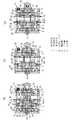
また、実施形態4として、図4に示すように、入力段と中間段との間に伝達キャリア52を設けると共に、中間段を二つの歯車組とした例を説明する。なお、前述の三つの実施形態と重複する構成の説明は省略して差異点のみを述べる。 Further, as a fourth embodiment, an example in which a
中間段が二つの歯車組となったことで、多段式変速機構部は第1歯車組1、第2歯車組2、第3歯車組3、に加えて、第4太陽歯車41と、第4遊星歯車43と、第4内歯歯車42と、第4伝達軸44と、第4遊星キャリア45と、からなる第4歯車組4を備えたものとなっている。 Since the intermediate stage has two gear sets, the multi-stage speed change mechanism unit includes the
詳しくは、入力段が第1歯車組1のままであり、中間段が第2歯車組2に加えて第3歯車組3を有するものとなり、出力段が一つずれて第4歯車組4になっている。 Specifically, the input stage remains the first gear set 1, the intermediate stage has the third gear set 3 in addition to the second gear set 2, and the output stage shifts by one to the fourth gear set 4. It has become.
そのため、第3遊星キャリア35に第4太陽歯車41が前面に一体で形成されて、出力軸72が第4遊星キャリア45の内周に一体で回転するよう固着されている。そして、第3内歯歯車32ではなく、第4内歯歯車42にクラッチ機構73が配設されたものとなっている。 Therefore, the
また、伝達キャリア52に圧入された連結軸53は、第2遊星キャリア25、第3太陽歯車31、第3遊星キャリア35、に加えて、第4太陽歯車41及び第4遊星キャリア45に軸心を同じくして回転自在で貫通している。 Further, the connecting
そして、連結軸53の前端に設けた直結用係合部54は、出力軸72の内周に設けた被係合部55に係脱自在となっており、直結用係合部54と被係合部55が係合すると、第2歯車組2、第3歯車組3、第4歯車組4の三つの歯車組を伝達経路から外すものとなっている。 Further, the direct
また、第2内歯歯車22はスライド移動可能であり、切替操作部83を操作することにより、第2内歯歯車22が回転可能の非減速状態となる前方位置と、第2内歯歯車22が回転不能にケース81に保持される減速状態となる後方位置と、を切替可能となっている。 The second
このように、減速・非減速状態に切り替わる可変段を中間段に備えると共に、中間段及び出力段を纏めて使用・非使用状態に切替可能としたことで、図4(a)に示すような中間段及び出力段を非使用状態にして入力段である第1歯車組1のみで回転を減速するモードと、図4(b)に示すような四つ全ての歯車組で回転を減速するモードと、図4(c)に示すような中間段の第2歯車組2を非減速状態にして第1歯車組1、第3歯車組3、第4歯車組4で回転を減速するモードと、の三つのモードに変速可能となっている。 As shown in FIG. 4A, the variable stage for switching between the deceleration and non-deceleration states is provided in the intermediate stage and the intermediate stage and the output stage can be switched to the use / non-use state collectively. A mode in which rotation is reduced only by the first gear set 1 as the input stage with the intermediate stage and the output stage being not used, and a mode in which rotation is reduced by all four gear sets as shown in FIG. A mode in which the second gear set 2 in the intermediate stage as shown in FIG. 4 (c) is brought into a non-decelerated state and the rotation is decelerated by the first gear set 1, the third gear set 3, and the fourth gear set 4. The three modes can be changed.
そして、回転伝達機器の減速比を最小とした際に、非減速状態の歯車組を出力軸72への回転駆動の伝達経路から外すことができる。 When the reduction ratio of the rotation transmission device is minimized, the non-decelerated gear set can be removed from the rotation drive transmission path to the
そのため、多段式変速機構部の慣性モーメントの増加を抑制できて、駆動初期に必要なエネルギーを低減すると共に、歯車の噛み合いによる伝達ロスが低減されて、回転伝達機器の回転駆動の伝達効率を向上することができる。 Therefore, the increase in the moment of inertia of the multi-stage transmission mechanism can be suppressed, reducing the energy required in the initial stage of driving and reducing the transmission loss due to the meshing of the gears, improving the transmission efficiency of the rotation drive of the rotation transmission device can do.
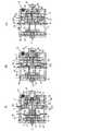
また、実施形態5として、図5に示すように、中間段を二つの歯車組にすると共に、伝達キャリア52を中間段の二つの歯車組の間に設けた例を説明する。なお、入力段を第1歯車組1、中間段を第2歯車組2及び第3歯車組3、出力段を第4歯車組4として、前述の実施形態4と重複する構成の説明は省略して差異点のみを述べる。 Further, as the fifth embodiment, as shown in FIG. 5, an example in which the intermediate stage has two gear sets and the
第1歯車組1は第1遊星キャリア15を備えておらず、第1太陽歯車11と第2太陽歯車21とが相対回転不能の段付歯車として一体で形成されたものとなっている。 The first gear set 1 does not include the first
そして、第1伝達軸14と第2伝達軸24とを一体とした二連伝達軸16が第1遊星歯車13と第2遊星歯車23とに回転自在で挿通されており、第1遊星歯車13と第2遊星歯車23とが互いに自転可能となっている。 A
更に、第1内歯歯車12及び第2内歯歯車22の外周面には切替用係合部が夫々設けてあり、該切替用係合部の外周側とケース81との間には内歯保持部材62が軸方向に沿ってスライド移動可能で配設されている。 Furthermore, a switching engagement portion is provided on each of the outer peripheral surfaces of the first
上記内歯保持部材62は切替操作部83を操作することでスライド移動して、前方位置と、後方位置と、に切替可能となっており、後方位置では第1内歯歯車12の第1切替用係合部121に係合し、前方位置では第2内歯歯車22の第2切替用係合部221に係合するものである。 The internal
そして、図5(b)に示すように、内歯保持部材62が後方位置にあり第1切替用係合部121に係合していると、第1内歯歯車12が回転不能に保持されるため、第1太陽歯車11によって第1遊星歯車13が公転して、二連伝達軸16を介して第2遊星キャリア25に回転駆動が伝達される。 As shown in FIG. 5B, when the internal
このとき、第2内歯歯車22は内歯保持部材62に保持されてないため、第2歯車組2は空転して非減速状態となっている。 At this time, since the second
また、図5(c)に示すように、内歯保持部材62が前方位置にあり第2切替用係合部221に係合していると、第2内歯歯車22が回転不能に保持されると共に、第1内歯歯車12が回転可能となり、第1歯車組1が非減速状態となる。 Further, as shown in FIG. 5C, when the internal
そのため、入力軸71からの回転駆動は第1太陽歯車11と一体である第2太陽歯車21に直接伝達されるものとなり、第2歯車組2が第2遊星キャリア25に入力軸71からの回転駆動を減速して伝達するものとなっている。 Therefore, the rotational drive from the
このように、内歯保持部材62のスライド移動により第1歯車組1と第2歯車組2との減速・非減速状態を交互に切り替えるものとなっている。 As described above, the first gear set 1 and the second gear set 2 are alternately switched between the deceleration state and the non-deceleration state by the sliding movement of the internal
また、第2遊星キャリア25に固着された駆動伝達ピン51にスライド移動可能な伝達キャリア52は、前方位置と、後方位置と、に切替可能であり、且つ前面に、第3太陽歯車31と、連結軸53とを備えている。 Further, the
そして、連結軸53の前端には第4太陽歯車41が固着されており、該第4太陽歯車41は伝達キャリア52のスライド移動によって第4遊星歯車43と係脱自在になっている。 A
また、第3太陽歯車31と第4太陽歯車41との間には連結軸53に回転自在で且つ共にスライド移動する連結歯車56が配置されており、連結歯車56は第3遊星キャリア35の内周に設けた連結係合部57に相対回転不能で且つスライド移動可能に係合している。 A connecting
なお、符号58は、伝達キャリア52をスライド移動した際に連結歯車56の後面が第3太陽歯車31の前面に接触して回転駆動時に一体で回転することを防止する接触防止部材である。
そして、連結軸53に固着された第4太陽歯車41が第4遊星歯車43に噛み合っていない際には、連結歯車56は上記第4太陽歯車41の代わりに第4歯車組4の太陽歯車として第4遊星歯車43に回転駆動を伝達するものとなっている。 When the
詳しくは、図5(a)に示すように、後方位置に伝達キャリア52がある状態では、第4太陽歯車41が第4遊星歯車43に噛み合っており、第4歯車組4を減速状態とすると共に、連結歯車56は第3遊星キャリア35の係合部にのみ係合するものとなっている。 Specifically, as shown in FIG. 5 (a), in a state where the
このとき、第3太陽歯車31と第3遊星歯車33とが噛み合わず、且つ連結歯車56が連結軸53に回転自在であり、連結歯車56に回転駆動が伝達されないため、第3歯車組3は出力軸72への回転駆動の伝達経路から外された非使用状態となる。 At this time, the
また、図5(b)に示すように、前方位置に伝達キャリア52がある状態では、第4太陽歯車41と第4遊星歯車43とが噛み合わずに、連結歯車56が第4遊星歯車43に噛み合い、第3遊星キャリア35からの回転駆動が第4歯車組4に伝達される状態となる。 Further, as shown in FIG. 5B, in the state where the
このとき、第3歯車組3及び第4歯車組4の両方が減速状態となり、伝達キャリア52に伝えられた入力軸71からの回転駆動は、第3歯車組3、第4歯車組4、出力軸72へと順に伝達される。 At this time, both the third gear set 3 and the fourth gear set 4 are decelerated, and the rotational drive from the
このように、切替操作部83により減速・非減速状態に切り替わる歯車組と、キャリア操作部84により使用・非使用状態に切り替わる歯車組と、を夫々独立して切替可能としたことで、図5(a)に示すような第2歯車組2を非減速状態にすると共に第3歯車組3を非使用状態にして第1歯車組1及び第4歯車組4で回転を減速するモードと、図5(b)に示すような第2歯車組2を非減速状態にして第1歯車組1、第3歯車組3、第4歯車組4で回転を減速するモードと、図5(c)に示すような第1歯車組1を非減速状態にして第2歯車組2、第3歯車組3、第4歯車組4で回転を減速するモードと、特に図示しないが第1歯車組1を非減速状態にすると共に第3歯車組3を非使用状態にして第2歯車組2及び第4歯車組4で回転を減速するモードと、の四つのモードに変速可能となっている。 As described above, the gear set that is switched to the deceleration / non-deceleration state by the switching
そして、上記四つのモードのいずれも出力段である第4歯車組4を回転駆動の伝達経路に有しており、常にクラッチ機構73を有効にしたものとなっており、常にトルククラッチが必要なドリルドライバー単機能の回転工具に適したものになっている。 Each of the above four modes has the fourth gear set 4 as the output stage in the rotational drive transmission path, and the
また、第3歯車組3を使用・非使用状態に切替可能としたことで、第3歯車組3を減速に用いない際に、第3歯車組3を回転駆動の伝達経路から外せるため、伝達ロスを低減できて、回転伝達機器の回転駆動の伝達効率が向上する。 Further, since the third gear set 3 can be switched between the use state and the non-use state, the third gear set 3 can be removed from the rotational drive transmission path when the third gear set 3 is not used for deceleration. Loss can be reduced and the transmission efficiency of the rotation drive of the rotation transmission device is improved.
なお、中間段の歯車組を三つ以上設けると共に、上記実施形態の切替手段を組み合わせたものにして、出力軸72への回転駆動をより複数速に変速可能としてもよい。もちろん、本発明の回転伝達機器は回転工具のみに用いるのではなく、本発明を変速手段として用いることが可能なものであれば、適宜採用可能である。 Note that three or more intermediate gear sets may be provided and the switching means of the above embodiment may be combined so that the rotational drive to the
1 第1歯車組
11 第1太陽歯車
12 第1内歯歯車
13 第1遊星歯車
14 第1伝達軸
15 第1キャリア
16 二連伝達軸
2 第2歯車組
21 第2太陽歯車
22 第2内歯歯車
23 第2遊星歯車
24 第2伝達軸
25 第2キャリア
3 第3歯車組
31 第3太陽歯車
32 第3遊星歯車
33 第3内歯歯車
34 第3伝達軸
35 第3キャリア
51 伝達ピン
52 伝達キャリア
53 連結軸
54 直結用係合部
55 被係合部
71 入力軸
72 出力軸
73 クラッチ機構
81 ケースDESCRIPTION OF
Claims (11)
Translated fromJapanese上記多段式変速機構部は、入力軸から回転駆動を受ける入力歯車組と、出力軸に回転駆動を出力する出力歯車組と、上記入力歯車組及び出力歯車組の間に少なくとも一つ以上配置された中間歯車組と、を有すると共に、上記歯車組の少なくとも一つに対して入力軸から入力された回転駆動を変速する変速状態及び上記回転駆動を変速しない非変速状態を切り替える歯車切替手段と、上記多段式変速機構部内の入力軸から上記出力軸へ回転駆動が伝達される伝達経路から上記歯車組の少なくとも一つを外す非使用状態及び上記伝達経路に加える使用状態を切り替える経路切替手段と、を備えており、
上記二つの切替手段の各状態の切替を組み合わせることで入力軸から入力された回転駆動を少なくとも三つの異なる速度モードに変速して出力軸に出力し、上記経路切替手段によって使用・非使用状態が切り替わる少なくとも一つの歯車組は、太陽歯車と、内歯歯車と、遊星歯車と、を有した遊星減速歯車組であり、
上記経路切替手段の少なくとも一つが、上記遊星減速歯車組とこの遊星減速歯車組より入力側の歯車組との間に配置されこの入力側の歯車組から上記太陽歯車に回転駆動を伝達する伝達キャリアであり、
該伝達キャリアが上記入力側の歯車組に対して上記太陽歯車を伴って軸方向に沿ってスライド移動自在であると共に、該スライド移動により上記太陽歯車が上記遊星歯車に係脱自在であり、
上記伝達キャリアは上記太陽歯車の離脱時に上記遊星減速歯車組を非使用状態にするものであることを特徴とする回転伝達機器。The rotation transmission device includes an input shaft to which rotational drive is input from a drive source, a multi-stage transmission mechanism that shifts the rotational drive input to the input shaft, and an output shaft that outputs the rotational drive that has been shifted. And
At least one or more of the multi-stage transmission mechanism is disposed between the input gear set that receives the rotational drive from the input shaft, the output gear set that outputs the rotational drive to the output shaft, and the input gear set and the output gear set. An intermediate gear set, and a gear switching means for switching between a shift state for shifting the rotational drive input from the input shaft to at least one of the gear sets and a non-shift state for not shifting the rotational drive; Path switching means for switching between a non-use state in which at least one of the gear sets is removed from a transmission path through which rotational drive is transmitted from the input shaft to the output shaft in the multi-stage transmission mechanism, and a use state applied to the transmission path; With
By combining the switching of each state of the two switching means, the rotational drive input from the input shaft is shifted to at least three different speed modes and output to the output shaft, and the use / non-use state is determined by the path switching means. The at least one gear set to be switched is a planetary reduction gear set having a sun gear, an internal gear, and a planetary gear,
A transmission carrier in which at least one of the path switching meansis disposed between the planetary reduction gear set and the input-side gear set from the planetary reduction gear set and transmits rotational drivefrom the input-side gear set to the sun gear. And
The transmission carrier is slidable along the axial direction with the sun gear withrespect to the gear set on the input side , and the sun gear is freely detachable from the planetary gear by the sliding movement,
The rotation transmission device according to claim 1, wherein the transmission carrier is configured to put the planetary reduction gear set in a non-use state when the sun gear is detached.
Priority Applications (1)
| Application Number | Priority Date | Filing Date | Title |
|---|---|---|---|
| JP2009015945AJP5379497B2 (en) | 2009-01-27 | 2009-01-27 | Rotation transmission equipment |
Applications Claiming Priority (1)
| Application Number | Priority Date | Filing Date | Title |
|---|---|---|---|
| JP2009015945AJP5379497B2 (en) | 2009-01-27 | 2009-01-27 | Rotation transmission equipment |
Publications (2)
| Publication Number | Publication Date |
|---|---|
| JP2010174936A JP2010174936A (en) | 2010-08-12 |
| JP5379497B2true JP5379497B2 (en) | 2013-12-25 |
Family
ID=42706111
Family Applications (1)
| Application Number | Title | Priority Date | Filing Date |
|---|---|---|---|
| JP2009015945AActiveJP5379497B2 (en) | 2009-01-27 | 2009-01-27 | Rotation transmission equipment |
Country Status (1)
| Country | Link |
|---|---|
| JP (1) | JP5379497B2 (en) |
Families Citing this family (2)
| Publication number | Priority date | Publication date | Assignee | Title |
|---|---|---|---|---|
| JP5750591B2 (en)* | 2011-01-21 | 2015-07-22 | パナソニックIpマネジメント株式会社 | Multi-speed tool |
| CN113108036A (en)* | 2021-03-11 | 2021-07-13 | 重庆大学 | Modular heavy load big velocity ratio transmission system modular mechanism |
Family Cites Families (6)
| Publication number | Priority date | Publication date | Assignee | Title |
|---|---|---|---|---|
| JPS62242163A (en)* | 1986-04-14 | 1987-10-22 | Matsushita Electric Works Ltd | Planetary change gear |
| JPH10151577A (en)* | 1996-11-26 | 1998-06-09 | Matsushita Electric Works Ltd | Rotary tool with transmission |
| JP3696493B2 (en)* | 2000-09-29 | 2005-09-21 | 株式会社マキタ | Planetary gear type transmission |
| JP4968494B2 (en)* | 2001-03-05 | 2012-07-04 | アイシン・エィ・ダブリュ株式会社 | Vehicle transmission |
| JP4063641B2 (en)* | 2002-11-07 | 2008-03-19 | 株式会社マキタ | Electric tool |
| WO2006102906A2 (en)* | 2005-04-01 | 2006-10-05 | Tomactech A/S | A planet gear |
- 2009
- 2009-01-27JPJP2009015945Apatent/JP5379497B2/enactiveActive
Also Published As
| Publication number | Publication date |
|---|---|
| JP2010174936A (en) | 2010-08-12 |
Similar Documents
| Publication | Publication Date | Title |
|---|---|---|
| JP5287576B2 (en) | Vehicle drive device | |
| JP6286460B2 (en) | Planetary gear mechanism and transmission | |
| EP2616712B1 (en) | Multi-speed drive unit | |
| JP4973487B2 (en) | Multiple clutch transmission | |
| JP5860140B2 (en) | Automatic transmission device | |
| KR101262980B1 (en) | Automated manual transmission | |
| JP2008075665A (en) | Automatic transmission | |
| JP2009072903A (en) | Electric tool and transmission mechanism | |
| JP2013072464A (en) | Automatic transmission | |
| JP6546300B1 (en) | Transmission for motor | |
| JP6078401B2 (en) | Vehicle drive device | |
| JP5276272B2 (en) | Industrial vehicle transmission | |
| JP5379497B2 (en) | Rotation transmission equipment | |
| JP5329477B2 (en) | transmission | |
| KR20210047734A (en) | Driving apparatus for electric vehicle | |
| JP2013203260A (en) | Hybrid system | |
| JP2010203542A (en) | Double clutch automatic transmission | |
| KR101836508B1 (en) | Automated manual transmission | |
| JPH07198005A (en) | Transmission | |
| CN218817914U (en) | Power system and vehicle | |
| JP2011144853A (en) | Multistage switching transmission | |
| JP4425208B2 (en) | Automatic transmission | |
| JP4458017B2 (en) | Hybrid drive unit | |
| JP6265014B2 (en) | Automatic transmission for vehicle | |
| JP2002106651A (en) | Planetary gear transmission |
Legal Events
| Date | Code | Title | Description |
|---|---|---|---|
| RD04 | Notification of resignation of power of attorney | Free format text:JAPANESE INTERMEDIATE CODE: A7424 Effective date:20100715 | |
| A621 | Written request for application examination | Free format text:JAPANESE INTERMEDIATE CODE: A621 Effective date:20110322 | |
| A711 | Notification of change in applicant | Free format text:JAPANESE INTERMEDIATE CODE: A712 Effective date:20120113 | |
| A977 | Report on retrieval | Free format text:JAPANESE INTERMEDIATE CODE: A971007 Effective date:20120605 | |
| A131 | Notification of reasons for refusal | Free format text:JAPANESE INTERMEDIATE CODE: A131 Effective date:20120815 | |
| A521 | Written amendment | Free format text:JAPANESE INTERMEDIATE CODE: A523 Effective date:20121015 | |
| A131 | Notification of reasons for refusal | Free format text:JAPANESE INTERMEDIATE CODE: A131 Effective date:20130409 | |
| A521 | Written amendment | Free format text:JAPANESE INTERMEDIATE CODE: A523 Effective date:20130610 | |
| TRDD | Decision of grant or rejection written | ||
| A01 | Written decision to grant a patent or to grant a registration (utility model) | Free format text:JAPANESE INTERMEDIATE CODE: A01 Effective date:20130903 | |
| A61 | First payment of annual fees (during grant procedure) | Free format text:JAPANESE INTERMEDIATE CODE: A61 Effective date:20130927 | |
| R150 | Certificate of patent or registration of utility model | Ref document number:5379497 Country of ref document:JP Free format text:JAPANESE INTERMEDIATE CODE: R150 Free format text:JAPANESE INTERMEDIATE CODE: R150 |