JP5379151B2 - Intraocular graft delivery system - Google Patents
Intraocular graft delivery systemDownload PDFInfo
- Publication number
- JP5379151B2 JP5379151B2JP2010534142AJP2010534142AJP5379151B2JP 5379151 B2JP5379151 B2JP 5379151B2JP 2010534142 AJP2010534142 AJP 2010534142AJP 2010534142 AJP2010534142 AJP 2010534142AJP 5379151 B2JP5379151 B2JP 5379151B2
- Authority
- JP
- Japan
- Prior art keywords
- cannula
- implant
- distal
- graft
- carrier
- Prior art date
- Legal status (The legal status is an assumption and is not a legal conclusion. Google has not performed a legal analysis and makes no representation as to the accuracy of the status listed.)
- Active
Links
- 239000007943implantSubstances0.000claimsdescription87
- 230000007246mechanismEffects0.000claimsdescription11
- 238000003780insertionMethods0.000claimsdescription2
- 230000037431insertionEffects0.000claimsdescription2
- 210000001508eyeAnatomy0.000description39
- 238000000034methodMethods0.000description18
- 210000002159anterior chamberAnatomy0.000description17
- 208000010412GlaucomaDiseases0.000description12
- 210000001742aqueous humorAnatomy0.000description12
- 239000011162core materialSubstances0.000description11
- 210000004087corneaAnatomy0.000description10
- 230000004410intraocular pressureEffects0.000description10
- 210000000695crystalline lenAnatomy0.000description8
- 210000001585trabecular meshworkAnatomy0.000description7
- 238000011282treatmentMethods0.000description7
- 239000000126substanceSubstances0.000description6
- 239000007788liquidSubstances0.000description5
- 238000004891communicationMethods0.000description4
- 210000000554irisAnatomy0.000description4
- 230000002093peripheral effectEffects0.000description4
- 230000000284resting effectEffects0.000description4
- 210000001519tissueAnatomy0.000description4
- 206010030348Open-Angle GlaucomaDiseases0.000description3
- 230000013011matingEffects0.000description3
- 238000001356surgical procedureMethods0.000description3
- 201000004569BlindnessDiseases0.000description2
- 210000004240ciliary bodyAnatomy0.000description2
- 230000000916dilatatory effectEffects0.000description2
- 239000003814drugSubstances0.000description2
- 229940079593drugDrugs0.000description2
- 210000002919epithelial cellAnatomy0.000description2
- 235000015097nutrientsNutrition0.000description2
- 210000001328optic nerveAnatomy0.000description2
- 210000001747pupilAnatomy0.000description2
- 239000002699waste materialSubstances0.000description2
- 206010036346Posterior capsule opacificationDiseases0.000description1
- 230000005540biological transmissionEffects0.000description1
- 239000008280bloodSubstances0.000description1
- 210000004369bloodAnatomy0.000description1
- 230000017531blood circulationEffects0.000description1
- 210000004204blood vesselAnatomy0.000description1
- 238000007664blowingMethods0.000description1
- 210000004556brainAnatomy0.000description1
- 239000002775capsuleSubstances0.000description1
- 230000001886ciliary effectEffects0.000description1
- 239000002872contrast mediaSubstances0.000description1
- 201000010099diseaseDiseases0.000description1
- 208000037265diseases, disorders, signs and symptomsDiseases0.000description1
- 239000000975dyeSubstances0.000description1
- 239000012530fluidSubstances0.000description1
- 239000006260foamSubstances0.000description1
- 239000011521glassSubstances0.000description1
- 230000036541healthEffects0.000description1
- 230000007774longtermEffects0.000description1
- 238000007726management methodMethods0.000description1
- 238000004519manufacturing processMethods0.000description1
- 239000000463materialSubstances0.000description1
- 210000000056organAnatomy0.000description1
- 230000001991pathophysiological effectEffects0.000description1
- 230000005043peripheral visionEffects0.000description1
- 229920000515polycarbonatePolymers0.000description1
- 239000004417polycarbonateSubstances0.000description1
- 201000006366primary open angle glaucomaDiseases0.000description1
- 230000008569processEffects0.000description1
- 230000004044responseEffects0.000description1
- 230000001953sensory effectEffects0.000description1
- 210000003462veinAnatomy0.000description1
- 230000008320venous blood flowEffects0.000description1
- 230000000007visual effectEffects0.000description1
- 210000004127vitreous bodyAnatomy0.000description1
Images


Classifications
- A—HUMAN NECESSITIES
- A61—MEDICAL OR VETERINARY SCIENCE; HYGIENE
- A61F—FILTERS IMPLANTABLE INTO BLOOD VESSELS; PROSTHESES; DEVICES PROVIDING PATENCY TO, OR PREVENTING COLLAPSING OF, TUBULAR STRUCTURES OF THE BODY, e.g. STENTS; ORTHOPAEDIC, NURSING OR CONTRACEPTIVE DEVICES; FOMENTATION; TREATMENT OR PROTECTION OF EYES OR EARS; BANDAGES, DRESSINGS OR ABSORBENT PADS; FIRST-AID KITS
- A61F9/00—Methods or devices for treatment of the eyes; Devices for putting in contact-lenses; Devices to correct squinting; Apparatus to guide the blind; Protective devices for the eyes, carried on the body or in the hand
- A61F9/007—Methods or devices for eye surgery
- A61F9/00781—Apparatus for modifying intraocular pressure, e.g. for glaucoma treatment
Landscapes
- Health & Medical Sciences (AREA)
- Ophthalmology & Optometry (AREA)
- Heart & Thoracic Surgery (AREA)
- Surgery (AREA)
- Engineering & Computer Science (AREA)
- Biomedical Technology (AREA)
- Nuclear Medicine, Radiotherapy & Molecular Imaging (AREA)
- Vascular Medicine (AREA)
- Life Sciences & Earth Sciences (AREA)
- Animal Behavior & Ethology (AREA)
- General Health & Medical Sciences (AREA)
- Public Health (AREA)
- Veterinary Medicine (AREA)
- Prostheses (AREA)
Description
Translated fromJapanese本明細書で引例に挙げられている刊行物および特許出願はいずれも、個々の刊行物および特許出願が特定して尚且つ個別にその存在を指摘した結果として参照することで本件の一部を構成するようになる限りにおいて、まさにその程度に参考文献としてここに援用されている。 All publications and patent applications cited in this specification are incorporated herein by reference in their entirety as a result of identifying individual publications and patent applications and individually pointing to their existence. To the extent that it is configured, it is incorporated herein by reference to that extent.
本発明は、広義には、眼内に移植される装置および斯かる装置の搬送システムに関するものである。より狭義には、本発明は眼の或る領域内から眼の別な領域への流体伝達を容易にする装置の搬送システムに関連している。 The present invention broadly relates to devices implanted in the eye and transport systems for such devices. More specifically, the present invention relates to a delivery system for a device that facilitates fluid transmission from one region of the eye to another region of the eye.
合衆国国立衛生研究所(NIHすなわちUnited States National Institutes of Health)の国立眼科研究所(NEIすなわちNational Eye Institute)の起草報告書によると、緑内障は目下のところ世界中の回復不能な盲目の主因であり、更にまた、世界中の失明については白内障に次いで2番目の原因となっている。従って、国立眼科研究所起草報告書は、「この種の疾患の病態生理学的特性および管理方法の決定に引続き相応の傾注と手立てを講じることに専心することが重要である」と結論づけている。緑内障研究者は、高い眼圧と緑内障との間に強い相関関係があると見ている。このため、眼科治療の専門家らは緑内障の兆候が無いか患者の調査を定常的に行うにあたり、眼圧計として周知の装置を利用して眼圧を測定する手段を取っている。既存の眼圧計の大半が、眼の外表面に突風を一吹き吹付けることにより測定を行うものである。 According to a drafting report by the National Eye Institute of the United States National Institutes of Health (NIH), glaucoma is currently the leading cause of unrecoverable blindness worldwide. Furthermore, blindness worldwide is the second leading cause after cataract. Therefore, the National Ophthalmology Drafting Report concludes that "it is important to focus on appropriate devotion and measures following the determination of the pathophysiological characteristics and management of this type of disease." Glaucoma researchers see a strong correlation between high intraocular pressure and glaucoma. For this reason, specialists in ophthalmic treatment use a means for measuring intraocular pressure using a well-known device as a tonometer in order to constantly investigate a patient for signs of glaucoma. Most existing tonometers measure by blowing a gust of wind on the outer surface of the eye.
眼の概念は、液体の満ちた球体と定めることができる。眼内には2種類の液体が存在する。水晶体の背後の空洞には硝子液として周知の粘性液が充ちている。水晶体の前部の各空洞は眼房水として周知の液体が充ちている。物体を目視する場合は常に、人は硝子液と眼房水の両方を通して物体を視認している。 The concept of an eye can be defined as a sphere filled with liquid. There are two types of liquid in the eye. The cavity behind the crystalline lens is filled with a viscous liquid known as a glass liquid. Each cavity at the front of the lens is filled with a liquid known as aqueous humor. Whenever an object is viewed, a person views the object through both vitreous humor and aqueous humor.
また、物体を目視する場合は常に、人は眼の角膜と水晶体を通して物体を視認している。角膜および水晶体は、透明であるためには、血管が皆無である。従って、角膜および水晶体を血液が流れることは全く無いため、これらの組織に栄養分を供給することもこれらの組織から老廃物を除去することもない。その代わり、これら諸機能は眼房水によって行われる。眼房水が眼内を絶えず流動することで、血管が形成されていない眼の各部(例えば、角膜や水晶体など)に栄養分を供給している。眼房水がこのように流動することで、これら組織から老廃物をも除去している。 In addition, whenever the object is visually observed, the person visually recognizes the object through the cornea of the eye and the crystalline lens. The cornea and the lens are transparent because they are transparent. Therefore, no blood flows through the cornea and the lens, so no nutrients are supplied to these tissues and no waste products are removed from these tissues. Instead, these functions are performed by aqueous humor. As the aqueous humor constantly flows in the eye, nutrients are supplied to each part of the eye where the blood vessels are not formed (for example, the cornea and the lens). This flow of aqueous humor removes waste products from these tissues.
眼房水は毛様体として周知の器官により生産される。毛様体は継続的に眼房水を分泌する上皮細胞を含んでいる。健康な眼では、新たな房水が毛様体の上皮細胞によって分泌されると、房水流は前眼房から流出して小柱網を通りシュレム管に流入する。このような過剰な房水はシュレム管から静脈血流に入り、眼から出てゆく静脈血と一緒に搬出される。Aqueous humor is produced by an organ known as the ciliary body. The ciliary body contains epithelial cells that continuously secrete aqueous humor. In healthy eyes, when new aqueous humor is secreted by the ciliary epithelial cells, the aqueous humor flows out of the anterior chamber and into the Schlemm's canal through the trabecular meshwork. Such excess aqueous humor enters the venous blood flow from Schlemm's canal and is carried along with the venous blood leaving the eye.
眼の自然な排液メカニズムが適切な機能を停止してしまうと、眼圧が上昇し始める。研究者らは、長期に亘り高い眼圧を被ったことが原因で、眼から脳に知覚情報を送っている視神経が損傷を受けるという学説を立てている。このような視神経の損傷の結果として周辺視力の喪失を生じる。緑内障が進行するにつれて、患者が完全に失明するまでに視野狭窄がどんどん進む。When the natural drainage mechanism of the eye stops functioning properly, the intraocular pressure begins to rise. Researchers have theorized that the optic nerve, which sends sensory information from the eye to the brain, is damaged due to long-term high intraocular pressure. This loss of optic nerve results in a loss of peripheral vision. As glaucoma progresses, narrowing of the visual field continues until the patient is completely blind.
薬物治療のほかにも、緑内障について多様な外科治療が既に実施されている。例えば、かつては、房水の流れを前眼房から外眼静脈に方向付けるようにシャントが移植されていた(リー(Lee)・シェッペンス(Scheppens)共著、「房水路・静脈シャントおよび眼圧(Aqueous-Venous Shunt and Intraocular Pressure)」、研究眼科学(Investigative Ophthalmology)1996年2月刊)。それ以外の早期の緑内障治療用移植片は、前眼房から下位結膜泡状突起へ導通させていた(例えば、米国特許第4,968,296号および米国特許第5,180,362号)。もっと他には、前眼房からシュレム管の丁度内側の点まで通じているシャントがあった(シュピーゲル(Spiegel)ほか著、「シュレム管移植 − 原発開放隅角緑内障に罹った患者の眼圧を低下させる新規な方法(Schlemm’s Canal Implant: A New Method to Lower Intraocular Pressure in Patients with POAG)」、眼科外科手術とレーザー(Ophthalmic Surgery and Lasers)1999年6月刊、米国特許第6,450,984号)。米国国際特許出願第2007/0191863号および米国国際特許出願第2007/0010827号などには、緑内障移植片の搬送・配備システムが記載されている。米国国際特許出願第2007/0073275号および米国国際特許出願第2006/0149194号などには、シュレム管に接近するための外科手術装置が記載されている。 In addition to drug treatment, various surgical treatments for glaucoma have already been performed. For example, once a shunt was implanted to direct the flow of aqueous humor from the anterior chamber to the external ocular vein (Lee, Scheppens, “Aqueduct / venous shunt and intraocular pressure ( Aqueous-Venous Shunt and Intraocular Pressure ”, Investigative Ophthalmology, February 1996). Other early glaucoma treatment grafts were conducted from the anterior chamber to the lower conjunctival foam process (eg, US Pat. No. 4,968,296 and US Pat. No. 5,180,362). In addition, there was a shunt leading from the anterior chamber to a point just inside the Schlemm's canal (Spiegel et al., “Schlemm's canal transplantation-reducing intraocular pressure in patients with primary open angle glaucoma. A new method to reduce (Schlemm's Canal Implant: A New Method to Lower Intraocular Pressure in Patients with POAG), Ophthalmic Surgery and Lasers, June 1999, US Pat. No. 6,450,984). US International Patent Application No. 2007/0191863 and US International Patent Application No. 2007/0010827 describe glaucoma graft delivery and deployment systems. US Patent Application No. 2007/0073275 and US International Patent Application No. 2006/0149194 describe surgical devices for accessing Schlemm's canal.
本発明は、広義には、眼内移植片(例えば、緑内障治療に使用されるもの等)およびその搬送システムの開示を目的としている。特に、本発明は緑内障治療に有用な眼内移植片およびその搬送システムを目的としている。 The present invention is broadly directed to the disclosure of intraocular implants (eg, those used for the treatment of glaucoma) and their delivery systems. In particular, the present invention is directed to an intraocular implant useful for the treatment of glaucoma and its delivery system.
新規な緑内障治療用移植片が、本件と同一譲受人に譲渡された2007年9月24日出願の「眼内移植片(Ocular Implants)」という発明名称の米国特許出願連続番号第11/860,318号に記載されているが、斯かる発明の開示内容は本件の一部を構成している。先行技術の眼内移植片搬送システムは、本件記載の移植片を搬送および配備するのに効果的に利用することができない。更に、先行技術の緑内障治療用の移植片を搬送および配備するのに利用される搬送システムは、或る種の搬送システムの要件に対処し損なっている。 US Patent Application Serial No. 11 / 860,318 entitled “Ocular Implants” filed September 24, 2007, in which a new glaucoma treatment graft was assigned to the same assignee. However, the disclosure of such invention constitutes part of this case. Prior art intraocular graft delivery systems cannot be effectively used to deliver and deploy the implants described herein. Moreover, the delivery systems utilized to deliver and deploy prior art glaucoma treatment implants fail to address the requirements of certain delivery systems.
本発明の一局面は、眼内移植片を担体に取付けられた状態で患者の眼内に挿入する方法を提案するものであり、斯かる方法は、カニューレを前眼房に挿入する工程と、カニューレの遠位出口ポートを移動させてシュレム管と導通状態にする工程と、眼内移植片とその担体をカニューレの出口ポートを通り抜けてシュレム管内に前進させる工程とを含んでいる。眼内移植片に複数の開口が設けられている実施例においては、本発明の方法は、眼内移植片およびその担体をシュレム管内に前進させるにあたり、担体に移植片の複数の開口を封鎖させた状態で実施する工程を更に含んでいる。 One aspect of the present invention proposes a method of inserting an intraocular implant into a patient's eye while attached to a carrier, the method comprising inserting a cannula into the anterior chamber; Moving the cannula's distal outlet port into electrical communication with the Schlemm's canal, and advancing the intraocular implant and its carrier through the cannula's exit port and into the Schlemm's canal. In embodiments where the ocular implant is provided with multiple openings, the method of the present invention allows the carrier to seal the multiple openings of the implant as the ocular implant and its carrier are advanced into Schlemm's canal. The method further includes a step of performing in the state.
或る実施例においては、前記挿入する工程は眼の角膜を通してカニューレを挿入する工程を含んでいる。或る実施例においては、前記前進させる工程は眼内移植片を前進させるにあたり、片手操作式作動装置を眼の外に配した状態で実施する工程を含んでいる。 In some embodiments, the inserting step includes inserting a cannula through the cornea of the eye. In one embodiment, the advancing step includes the step of carrying out the one-handed operation device outside the eye for advancing the intraocular implant.
或る実施例においては、前記前進させる工程は、遠位鈍端面をシュレム管内に移動させる工程を含んでいる。前記前進させる工程はまた、眼内移植片をシュレム管の周囲60度から180度に亘って拡張させる工程を含んでいる。 In some embodiments, the advancing step includes moving the distal blunt end surface into Schlemm's canal. The advancing step also includes dilating the intraocular graft from 60 degrees to 180 degrees around Schlemm's canal.
或る実施例においては、本発明の方法はシュレム管内で移植片を回転させる工程を含んでいる。斯かる方法の或る実施例は、眼内移植片を担体から切離すにあたり、例えば、眼内移植片に遠位方向の力を加えると同時に担体に近位方向の力を加えるといった方法により担体と眼内移植片のうち少なくとも一方を互いに相関的に移動させることにより実施する工程を含んでいる。遠位方向の力を加える前記工程は、眼内移植片に遠位方向の力を加えるにあたり、押込み部材をカニューレ内に配備させた状態で実施する工程を含んでいる。 In certain embodiments, the methods of the present invention include the step of rotating the implant within Schlemm's canal. One embodiment of such a method is to detach the intraocular implant from the carrier, for example, by applying a distal force to the intraocular implant and simultaneously applying a proximal force to the carrier. And at least one of the intraocular implants is moved relative to each other. The step of applying a distal force includes the step of applying a distal force to the intraocular implant with the pusher member deployed within the cannula.
担体の一部の直径が残余の部分よりも小さくされた実施例においては、前記切離す工程は担体の小さい方の直径部分に相関的に眼内移植片を配向する工程を含んでいるようにしてもよい。前記前進させる工程はまた、移植片嵌合機構が設けられた押込み部材を使って眼内移植片を前進させる工程を含んでおり、このような事例では、前記切離す工程は担体の小さい方の直径部分に相関的に眼内移植片および移植片嵌合機構を配向する工程を含んでいる。 In an embodiment in which the diameter of a portion of the carrier is made smaller than the remaining portion, the cutting step includes the step of orienting the intraocular graft relative to the smaller diameter portion of the carrier. May be. The step of advancing also includes the step of advancing the intraocular implant using a pusher member provided with a graft engagement mechanism, and in such cases, the step of detaching comprises the smaller of the carrier. Orienting the intraocular graft and graft fitting mechanism relative to the diameter portion.
或る実施例は、担体を眼から取出す工程を含んでいる。本発明の方法はまた、移植片の近位部が前眼房に残存しており尚且つ移植片の遠位部がシュレム管内に存在しているようになった場合には移植片をシュレム管内へ前進させるのを止める工程を含んでいるようにしてもよい。本発明の方法はまた、担体を通してシュレム管内に物質を搬入する工程を含んでいることもある。 Some embodiments include removing the carrier from the eye. The method of the present invention also allows the graft to be placed in the Schlemm's canal when the proximal portion of the graft remains in the anterior chamber and the distal portion of the graft is present in the Schlemm's canal. The method may include a step of stopping the advancement. The method of the present invention may also include the step of carrying the substance through the carrier into Schlemm's canal.
本発明のもう1つの別な局面は、眼内移植片およびその搬送システムを提案しており、斯かる搬送システムは眼のシュレム管部分に挿入するのに適した構成の遠位出口ポートが設けられたカニューレと、眼内移植片と、移植片の内側に配備されてカニューレの内部を移植片と一緒に移動自在である担体と、カニューレの遠位出口ポートが眼の中に位置している場合に担体と移植片のうち少なくとも一方を移動させるように眼の外側から操作するのに適した構成の近位制御部とを備えている。 Another aspect of the present invention proposes an intraocular implant and its delivery system, which is provided with a distal outlet port configured to be suitable for insertion into the Schlemm's canal portion of the eye. A cannula, an intraocular implant, a carrier that is deployed inside the implant and is movable with the implant inside the cannula, and a distal outlet port of the cannula is located in the eye A proximal control configured to be manipulated from the outside of the eye to move at least one of the carrier and the implant in some cases.
或る実施例においては、眼内移植片には複数の開口が設けられており、担体はこれら開口を閉鎖するように配向される。眼内移植片およびその担体が一緒に遠位鈍端を形成しているようにしてもよい。或る実施例においては、カニューレは、例えば、約0.1インチよりも小さい曲率半径を有している円弧の形状を呈しており、直径が約0.03インチよりも小さくなるようにするとよい。 In some embodiments, the intraocular implant is provided with a plurality of openings and the carrier is oriented to close the openings. The intraocular implant and its carrier may together form a distal blunt end. In some embodiments, the cannula may have, for example, an arc shape having a radius of curvature that is less than about 0.1 inches and a diameter that is less than about 0.03 inches.
或る実施例においては、担体は残余よりも直径が大きい部分とそこよりも直径が小さい部分から構成されており、眼内移植片は担体の大きい方の直径部分と嵌合する。或る実施例はまた、カニューレの内側に配備されて眼内移植片と係合する押込み部材を備えており、斯かる押込み部材が近位制御部に作動可能に接続されているようにしてもよい。押込み部材は、カニューレの出口ポートを通り抜けて進入中に眼内移植片を保持したままにするのに適した構成の移植片嵌合機構を備えているようにしてもよい。眼内移植片は、担体の大きい方の直径部分と移植片嵌合機構との間に配備されると移植片嵌合機構と係合状態になることができ、眼内移植片は、担体の小さい方の直径部分と移植片嵌合機構との間に配備されると移植片嵌合機構から切離すことができる。 In some embodiments, the carrier is composed of a portion with a larger diameter than the rest and a portion with a smaller diameter, and the intraocular implant fits into the larger diameter portion of the carrier. Some embodiments also include a pusher member that is deployed inside the cannula and engages the intraocular implant, such that the pusher member is operatively connected to the proximal control. Good. The pusher member may include a graft fitting mechanism configured to be suitable for holding the intraocular graft through the cannula's outlet port and during entry. The intraocular implant can be engaged with the graft engagement mechanism when deployed between the larger diameter portion of the carrier and the graft engagement mechanism, When deployed between the smaller diameter portion and the graft mating mechanism, it can be disconnected from the graft mating mechanism.
或る実施例においては、担体には、近位制御部内の物質入口と導通している物質搬送管腔が設けられている。 In some embodiments, the carrier is provided with a substance delivery lumen in communication with a substance inlet in the proximal control.
或る実施例においては、近位制御部はカニューレと接続されている遠位操作部と担体移動用作動装置が設けられた近位操作部とを備えており、近位操作部および遠位操作部は互いに相関的に運動自在である。近位操作部にはまた、移植片移動用作動装置も設けられている。 In one embodiment, the proximal control unit includes a distal operation unit connected to the cannula and a proximal operation unit provided with an actuator for moving the carrier. The parts can move relative to each other. The proximal operating part is also provided with an actuator for moving the graft.
本発明のもう1つ別な局面は眼内移植片を患者の眼に挿入する方法を対案しており、斯かる方法は、カニューレを眼の前眼房に挿入する工程と、カニューレ係止部材が小柱網に係止するまでカニューレの遠位カッター部を小柱網に通してシュレム管の中に移動させる工程と、係止部材を小柱網に係止させた後で眼内移植片をカニューレの出口ポートを通り抜けてシュレム管内に進入させる工程とを含んでいる。 Another aspect of the present invention contemplates a method for inserting an intraocular implant into a patient's eye, the method comprising inserting a cannula into the anterior chamber of the eye, and a cannula locking member. Moving the distal cutter portion of the cannula through the trabecular mesh into the Schlemm's canal until the locking member is locked to the trabecular mesh, and the intraocular implant Through the outlet port of the cannula and into the Schlemm's canal.
或る実施例においては、前記挿入する工程は、眼の角膜に通してカニューレを挿入する工程を含んでいる。或る実施例においては、前記進入させる工程は、眼内移植片を前進させるにあたり、片手操作式作動装置を眼の外に配備した状態で実施する工程を含んでいる。 In some embodiments, the inserting step includes inserting a cannula through the cornea of the eye. In one embodiment, the advancing step includes the step of performing the one-handed operation device deployed outside the eye to advance the intraocular implant.
或る実施例においては、前記進入させる工程はまた、眼内移植片をシュレム管の周囲60度から180度に亘って拡張させる工程を含んでいるようにしてもよい。 In some embodiments, the advancing step may also include the step of dilating the intraocular graft from 60 degrees to 180 degrees around Schlemm's canal.
本発明の方法はまた、シュレム管の内部で移植片を回転させる工程と、前記進入させる工程の最中にカニューレに前方に向かう圧力を加え続けながらカニューレの少なくとも一部を変形させる工程と、眼内移植片を搬送装置から切離す工程のうち一工程以上を含んでいるようにするとよい。搬送装置が押込み部材を備えている実施例においては、前記進入させる工程は、押込み部材を使って眼内移植片の遠位端にカニューレの出口ポートの中を前進させる工程を含んでいる。 The method also includes rotating the implant within Schlemm's canal, deforming at least a portion of the cannula while continuing to apply forward pressure to the cannula during the step of entering, It is preferable to include one or more steps among the steps of separating the internal graft from the transport device. In embodiments where the delivery device comprises a pusher member, the advancing step includes advancing the cannula outlet port with the pusher member to the distal end of the intraocular graft.
前記進入させる工程の或る実施例は、移植片が担体の上を伝ってシュレム管の中へ前進する工程を含んでいる。斯かる方法はまた、例えば、眼内移植片を担体から切離すことにより、担体を眼から取出す工程を含んでいるようにしてもよい。或る実施例においては、物質が担体の中に通してシュレム管の内部に搬入される。本発明の実施例はまた、移植片の近位部が前眼房に残存しており尚且つ移植片の遠位部がシュレム管内に存在しているようになった場合には移植片をシュレム管内へ前進させるのを止める工程を含んでいる。 One embodiment of the advancing step includes advancing the implant over the carrier and into Schlemm's canal. Such a method may also include the step of removing the carrier from the eye, for example, by severing the intraocular implant from the carrier. In some embodiments, the substance is passed through the carrier and into the Schlemm's canal. Embodiments of the present invention also provide for implanting the graft when the proximal portion of the graft remains in the anterior chamber and the distal portion of the graft is present in the Schlemm's canal. Stopping the advancement into the tube.
本発明のまた別な局面はカニューレおよび近位制御部を備えている眼内移植片システムを提案しており、該カニューレは移植片管腔と、遠位出口ポートと、出口ポートの輪郭の少なくとも一部を画定している遠位カッター部と、解剖学的肉体管腔の内部において出口ポートが目下位置している一点で遠位カッター部が該肉体管腔の中へ進入するのを抑制する係止部材とを有しており、該近位制御部は、カニューレの遠位出口ポートが眼の中に在る時に眼の外部から操作されるのに適した構成である。 Another aspect of the present invention proposes an intraocular graft system comprising a cannula and a proximal control, the cannula comprising at least a graft lumen, a distal outlet port, and an outlet port profile. A distal cutter part defining a part and a point where the exit port is currently located inside the anatomical body lumen prevent the distal cutter part from entering the body lumen And the proximal control is configured to be manipulated from outside the eye when the cannula's distal outlet port is in the eye.
或る実施例においては、カニューレは、例えば、曲率半径が0.1インチよりも小さく、直径が約0.03インチよりも小さく、または、その両方の条件を満たしているような円弧の形状を呈している。カッター部の切開刃はカニューレの中心軸線に対して角度付けされており、或る実施例においては、切開刃は中心軸線に対して約10度から約80度の角度を成しているようにするとよい。或る実施例はまた、係止部材が切開刃の近位側の部分に配置されていてもよい。 In some embodiments, the cannula has an arcuate shape such that, for example, the radius of curvature is less than 0.1 inches, the diameter is less than about 0.03 inches, or both. The cutting blade of the cutter section is angled with respect to the central axis of the cannula, and in one embodiment, the cutting blade is at an angle of about 10 degrees to about 80 degrees with respect to the central axis. Good. Some embodiments may also include a locking member disposed on a proximal portion of the cutting blade.
或る実施例は担体を更に備えており、斯かる担体はカニューレの内部に配備されているとともに移植片を担荷支持するのに適した構成であり、尚且つ、出口ポートを通り抜ける寸法に設定されている。更にまた、斯かる実施例は眼内移植片を備えており、斯かる眼内移植片は担体と嵌合状態になるようにしてもよい。担体が残余より直径が大きい部分およびそこより直径が小さい部分から構成されている実施例では、眼内移植片は担体の大きい方の直径部分と嵌合するようになっていてもよい。担体に物質搬送管腔が設けられているようにしてもよい。 Some embodiments further comprise a carrier that is disposed within the cannula and is suitable for carrying the graft and is dimensioned to pass through the outlet port. Has been. Furthermore, such embodiments may include an intraocular implant, which may be in engagement with the carrier. In embodiments where the carrier is composed of a larger diameter portion than the remainder and a smaller diameter portion, the intraocular implant may be adapted to mate with the larger diameter portion of the carrier. The carrier may be provided with a substance conveyance lumen.
本発明の或る実施例はまた、カニューレの内部に配備されて眼内移植片と嵌合状態になる押込み部材を備えており、斯かる押込み部材は近位制御部に作動可能に接続されている。斯かる実施例はまた、カニューレの出口ポートを通り抜けて前進している最中は眼内移植片を保持したままであるのに適した構成の移植片嵌合機構を備えているようにしてもよい。 Certain embodiments of the present invention also include a pusher member that is deployed within the cannula to mate with the intraocular implant, such pusher member operably connected to the proximal control. Yes. Such an embodiment may also include a graft fitting mechanism configured to be suitable for retaining the intraocular graft during advancement through the outlet port of the cannula. Good.
或る実施例においては、近位制御部はカニューレに接続されている遠位操作部と、担体移動用作動装置が設けられた近位操作部とを有しているが、近位操作部と遠位操作部は互いに相関的に移動自在である。近位操作部は移植片移動用作動装置を備えているようにしてもよい。 In one embodiment, the proximal control unit includes a distal operation unit connected to the cannula and a proximal operation unit provided with a carrier moving actuator, The distal operation parts are movable relative to each other. The proximal operation unit may be provided with an implant moving actuator.
後段の詳細な説明は添付の図面を参照しながら読むべきものであり、添付の図面では複数の相互に異なる図において同一部材は同一参照番号が付されている。図面は、必ずしも等尺ではないが、本発明の具体的な実施例を描画したものであり、本発明の範囲を制限するものと解釈するべきではない。構成、素材、寸法、製造プロセスの各種具体例は選ばれた一部部材について提示されたものである。それ以外の部材は全て、本発明の技術分野の当業者には周知のものを採用している。提案されている具体例の大半の代わりに好適な代替例を採用してもよいことを、当業者は認識するであろう。 The following detailed description should be read with reference to the accompanying drawings, in which like reference numerals refer to like parts throughout the several views. The drawings are not necessarily to scale, but depict specific embodiments of the invention and should not be construed as limiting the scope of the invention. Various specific examples of the structure, material, dimensions, and manufacturing process are presented for some selected members. All other members are well known to those skilled in the art of the present invention. Those skilled in the art will recognize that suitable alternatives may be employed instead of most of the proposed examples.
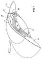
図1は人の眼10を様式化して描いたものであり、角膜12が瞳14および虹彩16を覆っているとともに、虹彩を越えた直ぐ外側の鞏膜18をも覆っているのを例示している。前眼房20は角膜の背後にあって、尚且つ、瞳、虹彩、および、水晶体の前面側に存している。上述のように、健康な眼においては、眼房水は前眼房20から流出してから、虹彩16の外側端縁に位置している小柱網22を通ってシュレム管24に流入する。 FIG. 1 is a stylized depiction of a
図2から図8は、眼内移植片100がカニューレ102によりシュレム管104に搬入されているのを例示している。(これら図面では図示を容易にするために、シュレム管は湾曲させずに直状であるものと例示されている。)図示の眼内移植片は、2007年9月24日出願の「眼内移植片(Ocular Implants)」という名称の米国特許出願連続番号11/860,318号により詳細に記載されている。それ以外の眼内移植片も本発明の搬送システムによって搬送および配備することができるものと理解するべきである。 FIGS. 2-8 illustrate the
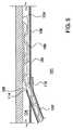
図2に例示されているように、カニューレ102の遠位部は角膜を貫いて前眼房101の内部に位置しているとともに小柱網106を刺通した結果、カニューレ102の遠位出口ポート108がシュレム管104と導通可能となっている。この実施例においては、図3および図4により詳細に例示されているように、カニューレ102は剛性の湾曲した管であり、カッター部110が出口ポート108に設けられている。或る実施例においては、カニューレ102はシュレム管への正接入射を達成するような湾曲状態を成しており、そのために例えば、約0.1インチよりも小さい曲率半径の円弧の形状を取らせる方法を採用している。それ以外の実施例では、他の形状および他の湾曲状態を呈するようにしてもよい。 As illustrated in FIG. 2, the distal portion of the
この実施例においては、カッター部110は尖点114で合流している2辺の凸状刃112から形成されている。他の実施例においては、カッターの刃は凹状でも直状でもよい。図示のように、刃112は尖点114から2辺の刃112の交点に形成されている1対の任意の係止部材116まで延在していると同時に、任意のカニューレ張出し部118が設けられている。図2に例示されているように、カニューレ102の遠位端は前眼房101の内側を前進して小柱網106に向かわせられる。カニューレ102の遠位端が小柱網に合流すると、カッター部110の尖点114および刃112を前進させて小柱網を貫いてシュレム管の中に伸び入るが、張出し部118は折れ戻って前眼房101の内部に残存する。係止部材116が小柱網に係止すると、カニューレ102の遠位方向移動が止まる。 In this embodiment, the
或る実施例においては、カニューレ102は、直径が約0.030インチよりも小さい透明なポリカーボネート管材から形成されており、この直径は例えば、外径が0.028インチで内径が0.014インチであるとよい。カッター刃が係止部材までつながっている実施例においては、カッター刃はカニューレの中心軸線に対して約10度から80度の間の角度を成しており、係止部材は尖点114の内側で直径の中点付近に位置しているようにするとよい。カニューレ張出し部が設けられている実施例においては、張出し部118は尖点114を約1.5 mm越えた先まで延びているようにするとよい。それ以外の諸機能のうちで、カニューレに前方向への圧力が加えられつづけている状態で(例えば、図2に例示されているように)、張出し部118を屈曲させることで、操作者は小柱網に係止させてカニューレの遠位端を正確に位置決めした確かな手応えを得ることができる。 In some embodiments, the
搬送中、眼内移植片100は、カニューレ102の内部に移植片を保持したままで移動自在である担体120に取付けられている。それ以外の諸機能のうち、担体120の1つの特殊機能は、移植片100に設けられている複数の開口122を閉鎖して、移植片を前進させている時に移植片とシュレム管104の内側の組織との干渉を最小限に抑えるようにしている。この実施例においては、眼内移植片100には遠位鈍端124が設けられており、眼の組織を損傷するのを回避するよう図っている。他の実施例においては、遠位鈍端の少なくとも一部は担体に設けられているようにしてもよい。 During delivery, the
この実施例においては、図6に例示されているように、押込み部材126は眼内移植片100の近位端128と嵌合状態になっており、カニューレ102の出口ポート108を通り抜けてシュレム管内に移植片を前進させる。担体120は近位方向に押込み部材126の中に張出し、例えば、眼の外部にある片手操作式作動装置(図示せず)に向かって延びている。 In this embodiment, as illustrated in FIG. 6,
移植片100の近位端128のみが前眼房101の中に残存している状態になると、移植片をシュレム管内に前進させるのを停止する。眼内移植片の設計次第では、移植片はこの時点でシュレム管の周囲60度から180度に亘って拡張している。また、この時点で、または、それ以前に、適切な配向を達成するためにシュレム管内で移植片を回転させることができるようにしてもよい。次に、図7に例示されているように、担体120に近位方向の力が加えられて(例えば、体外の作動装置または制御装置によって)移植片100から近位方向に担体を引き離しながら、押込み部材126が遠位方向に向かう力を加えて(ここでもまた、体外の作動装置または制御装置によって)移植片100を適所に維持することができる。続いて、担体120、押込み部材126、および、カニューレ102が眼から引き抜かれて、移植片の近位入口端128を前眼房101の内部に置いてシュレム管内に移植片を放置することができる。 When only the
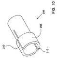
図9から図11は、眼内移植片(図2から図8に例示されている移植片100)とその搬送システムとの嵌合機構の一実施例の詳細を示している。この実施例においては、担体200には、遠位側の直径が減じられた部分202と近位側の直径が増大した部分204が設けられている。押込み部材206の遠位端には、移植片の近位端128と係合する内側リップ部材207と移植片の近位端128を包囲している輪部材208が設けられている。図10に例示されているように、1本以上の長軸線方向のスリット210を輪部材208に形成することで、輪部材208が放射方向に拡張するのを許容している。更に、本実施例の移植片100には、図8に例示されているように、開放路近位端128が設けられており、この近位端も放射方向に拡張することができる。図9に例示されている嵌合配置にある時には、担体の直径が増大している部分204は移植片100の近位端の内側に位置しており、延いては、押込み部材206の輪部材208の内側に配置されている。担体の直径が増大している部分204の直径は輪部材208の静止時直径および移植片128の静止時直径よりも大きせいで、輪部材208および移植片128がそれぞれの静止時の形状から放射方向に張出す。よって、このような配置では、押込み部材、移植片、および、担体は摩擦嵌め状態を呈し、一緒に単一部材として移動することができるようになる。 9 to 11 show details of an embodiment of the fitting mechanism between the intraocular implant (
移植片を搬送システムから切離すために、図11に例示されているように直径が減じられた部分202が移植片の近位部128および輪部材208の内側に位置するようになるまで、担体200が近位方向に引き抜かれる(代替例として、移植片が遠位方向に前進移動させられてもよい)。直径が減じられた部分202の直径が移植片の近位部128の静止時内径よりも小さいため、移植片は搬送システムの担体から放出される。ここで、押込み部材を近位方向に引き抜くだけで、押込み部材を移植片から切離すことができる。 To detach the graft from the delivery system, the carrier until the reduced-
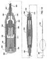
図12および図13は、本発明の移植片および搬送システムの片手操作式作動装置の実施例を示している。この実施例においては、作動装置の諸機能は2個の作動装置、すなわち、近位操作部300および遠位操作部302の間で分与されている。図示を簡易にするために、図12および図13ではカニューレおよび移植片を省いている。眼内移植片の担体304は押込み部材306の中を近位方向に通って遠位操作部302の中まで延びている。この実施例では、押込み部材306は近位押込み管308と、近位押込み管308の内面に接着されている、遠位側の直径が減じられた押込み管310とから構成されている。担体304は遠位スリーブ312を通り、更にまた、近位芯材管314の遠位部を通り抜けて近位方向に延びている。(近位芯材管314は図12の平面図および図13の断面図に例示されている。)担体304の拡大近位端316は、近位芯材管314の内側では遠位スリーブ312の近位端と遠位係止部材318の間に置かれている。担体304の拡大近位端316はスリーブ312の内径および係止部材318の内径よりも大きい。従って、担体304は近位芯材管314に相関的に限られた量だけ長軸線方向に移動させることができるにすぎない。 12 and 13 show an embodiment of the one-hand operated actuator of the implant and delivery system of the present invention. In this embodiment, the functions of the actuating device are distributed between two actuating devices, namely the
上述のカニューレなどのようなカニューレ(図示せず)の近位端と係合するように、遠位操作部302の遠位端にルアー取付け部材320(または、それ以外の好適な連結具)が設けられている。よって、カニューレおよび移植片を前進させて眼の中に入れる際の制御は、眼と相関的に遠位操作部302を移動させることによって行われる。或る実施例においては、近位押込み管308の外側面には少なくとも1つの平坦面(例えば、6角形面)が設けられており、この平坦面が遠位操作部302の内側面でこれに対応する形状の部位と嵌合し、カニューレと相関的に操作部302を回転させることで、押込み部材および移植片を回転させるようにしている。 There is a luer attachment member 320 (or other suitable connector) at the distal end of the
編組管322は遠位操作部302の近位端から近位操作部300の遠位端まで遠位応力逃がし部326および近位応力逃がし部324を介して近位方向に延在している。編組管322により操作部300、302は互いに相関的に回転させることができ、それにより、操作部300の意図せぬ回転により操作部302を回転させてしまうことがないようにしている。 The
近位押込み管308は遠位操作部302および編組管322を通って近位操作部300の内部の押込み管係止部材328に向けて近位方向に延びており、近位操作部300に接着されている。係止部材328は栓330により押込み管作動装置332の内部の適所に保持される。この実施例においては、係止部材328および近位押込み管308は、押込み管作動装置332に対して自由に回転することができる。押込み管作動装置332はその外周ネジが静止操作部333の内周ネジと螺合している。近位芯材管314は近位押込み管308を越えて芯材管係止部材334まで更に近位方向に延びており、この係止部材に接着されている。係止部材334は丸天井型栓338により芯材管作動装置336の内部の適所に保持されている。この実施例においては、係止部材334および近位芯材管314は芯材管作動装置336に対して自由に回転することができる。芯材管作動装置336はその外周ネジが押込み管作動装置332の内周ネジと螺合している。 The
この実施例の2操作部式の設計により、眼内移植片およびその搬送システムを2名の操作者により同時操作することができるようになる。使用時には、眼内移植片(例えば、上述の移植片など)は担体304に取付けられて、遠位操作部302のルアー取付け部材320に付着されたカニューレ(上述のカニューレなど)の内部に配備される。前房隅角レンズを利用して目視で観察しながら、医者は遠位操作部302を前進させることによりカニューレの遠位端を患者の角膜に設けられた開口に通して前眼房に進入させる。カニューレが小柱網を通り抜けてカニューレ遠位出口ポートがシュレム管と導通状態になると、近位操作部300を握っている助手は、作動装置332のネジと操作部333のネジとが螺合しているおかげで押込み管308および担体304を操作部333、遠位操作部302、および、カニューレと相関的に遠位方向に移動させる作動装置332、336を同時に回転させることにより、担体および移植片をカニューレの遠位出口ポートから外へ出してシュレム管に進入させる。 The two-operator design of this embodiment allows the intraocular implant and its delivery system to be operated simultaneously by two operators. In use, an intraocular implant (eg, the implant described above) is attached to the
移植片をシュレム管の中で十分な距離だけ進入させてから、作動装置332に対して作動装置336を回転させて担体304を押込み管308に対して近位方向に移動させることにより、移植片は搬送システムから切離され、それにより、担体が引き抜かれている間も移植片は静止状態に維持される。移植片の配備が完了して搬送システムから切離されてしまった後、押込み部材、担体、および、カニューレが患者の眼から取出される。 The implant is allowed to enter the Schlemm's canal by a sufficient distance and then the
図14は本発明による眼内移植片およびその搬送システムのもう1つ別な実施例を示している。(先に説明した各実施例のものに類似している各部材は同一参照番号が付与されている。)この実施例は、担体と相互作用する近位芯材管を省いている。その代わりに、担体304は丸天井型栓338を通って近位取付け部材400(例えば、ルアー取付け部材など)に向けて近位方向に延びており、斯かる近位取付け部材400はその入口401が担体304の中央管腔と導通している。本発明の眼内移植片は、担体304の中央管腔と一線に並んでいる遠位出口ポート402を備えている。物質(例えば、染料、造影剤、薬など)は近位取付け部材400を通って担体304に注入されてから移植片100の遠位出口ポート402を通り抜けて、必要に応じて患者の眼に入る。先に説明した実施例と同様に、移植片がシュレム管の中で十分な距離だけ進入完了すると、作動装置332と相関的に作動装置336を回転させて担体304を押込み管308に対して近位方向に移動させることにより、移植片は搬送システムから切離され、それにより、担体を引き抜いている最中も移植片は静止状態に保たれる。移植片の配備が完了して搬送システムから切離されてしまった後で、押込み部材、担体、および、カニューレは患者の眼から取出される。或る実施例においては、近位取付け部材400および担体304を回転させることにより、移植片100を回転させることができる。 FIG. 14 shows another embodiment of an intraocular implant and its delivery system according to the present invention. (Each member similar to that of the previously described embodiments has been given the same reference number.) This embodiment omits the proximal core tube that interacts with the carrier. Instead, the
Claims (6)
Translated fromJapanese眼のシュレム管に挿入するのに適した構成の遠位カッター部と遠位出口ポートが設けられた湾曲したカニューレと、
前記カニューレ内に配置されて複数の開口を有する眼内移植片と、
前記カニューレ内に配置されて前記眼内移植片と係合する押込み部材と、
前記押込み部材と作動的に連結され、眼の外部から操作するのに適した構成であり、カニューレの前記遠位出口ポートが眼の中に位置するようになると、移植片を移動させる近位制御部とを備えている、システム。An intraocular graft delivery system,
Acurved cannula provided with adistal cutter portion and a distal outlet port configured for insertion into the Schlemm's canal of the eye;
An intraocular implant disposed within the cannula and having a plurality of openings;
A pusher member disposed within the cannula and engaged with the intraocular implant;
Proximal control that isoperatively connected to the pusher member and adapted to be manipulated from outsidethe eye and that moves the implant when the distal outlet port of the cannula is positioned in the eye A system comprising a part.
Applications Claiming Priority (3)
| Application Number | Priority Date | Filing Date | Title |
|---|---|---|---|
| US11/943,289US8512404B2 (en) | 2007-11-20 | 2007-11-20 | Ocular implant delivery system and method |
| US11/943,289 | 2007-11-20 | ||
| PCT/US2008/083223WO2009067369A1 (en) | 2007-11-20 | 2008-11-12 | Ocular implant delivery system and method |
Publications (3)
| Publication Number | Publication Date |
|---|---|
| JP2011502710A JP2011502710A (en) | 2011-01-27 |
| JP2011502710A5 JP2011502710A5 (en) | 2012-01-12 |
| JP5379151B2true JP5379151B2 (en) | 2013-12-25 |
Family
ID=40642799
Family Applications (1)
| Application Number | Title | Priority Date | Filing Date |
|---|---|---|---|
| JP2010534142AActiveJP5379151B2 (en) | 2007-11-20 | 2008-11-12 | Intraocular graft delivery system |
Country Status (7)
| Country | Link |
|---|---|
| US (1) | US8512404B2 (en) |
| EP (2) | EP2636391B1 (en) |
| JP (1) | JP5379151B2 (en) |
| CN (2) | CN103054667B (en) |
| AU (1) | AU2008326619B2 (en) |
| CA (1) | CA2703280C (en) |
| WO (1) | WO2009067369A1 (en) |
Families Citing this family (82)
| Publication number | Priority date | Publication date | Assignee | Title |
|---|---|---|---|---|
| KR20020035476A (en) | 1999-04-26 | 2002-05-11 | 지엠피 비젼 솔루션즈 인코포레이티드 | Shunt device and method for treating glaucoma |
| US7867186B2 (en) | 2002-04-08 | 2011-01-11 | Glaukos Corporation | Devices and methods for treatment of ocular disorders |
| US6638239B1 (en) | 2000-04-14 | 2003-10-28 | Glaukos Corporation | Apparatus and method for treating glaucoma |
| US9603741B2 (en) | 2000-05-19 | 2017-03-28 | Michael S. Berlin | Delivery system and method of use for the eye |
| AU2002258754B2 (en) | 2001-04-07 | 2006-08-17 | Glaukos Corporation | Glaucoma stent and methods thereof for glaucoma treatment |
| US7431710B2 (en) | 2002-04-08 | 2008-10-07 | Glaukos Corporation | Ocular implants with anchors and methods thereof |
| US7331984B2 (en) | 2001-08-28 | 2008-02-19 | Glaukos Corporation | Glaucoma stent for treating glaucoma and methods of use |
| US7909789B2 (en) | 2006-06-26 | 2011-03-22 | Sight Sciences, Inc. | Intraocular implants and methods and kits therefor |
| US8308701B2 (en) | 2010-11-15 | 2012-11-13 | Aquesys, Inc. | Methods for deploying intraocular shunts |
| US20120123316A1 (en) | 2010-11-15 | 2012-05-17 | Aquesys, Inc. | Intraocular shunts for placement in the intra-tenon's space |
| US8852256B2 (en) | 2010-11-15 | 2014-10-07 | Aquesys, Inc. | Methods for intraocular shunt placement |
| US10085884B2 (en) | 2006-06-30 | 2018-10-02 | Aquesys, Inc. | Intraocular devices |
| US8974511B2 (en) | 2010-11-15 | 2015-03-10 | Aquesys, Inc. | Methods for treating closed angle glaucoma |
| US8828070B2 (en) | 2010-11-15 | 2014-09-09 | Aquesys, Inc. | Devices for deploying intraocular shunts |
| US8758290B2 (en)* | 2010-11-15 | 2014-06-24 | Aquesys, Inc. | Devices and methods for implanting a shunt in the suprachoroidal space |
| US8852137B2 (en) | 2010-11-15 | 2014-10-07 | Aquesys, Inc. | Methods for implanting a soft gel shunt in the suprachoroidal space |
| US8801766B2 (en) | 2010-11-15 | 2014-08-12 | Aquesys, Inc. | Devices for deploying intraocular shunts |
| US8721702B2 (en) | 2010-11-15 | 2014-05-13 | Aquesys, Inc. | Intraocular shunt deployment devices |
| US8663303B2 (en) | 2010-11-15 | 2014-03-04 | Aquesys, Inc. | Methods for deploying an intraocular shunt from a deployment device and into an eye |
| EP2088976B1 (en) | 2006-11-10 | 2019-07-03 | Glaukos Corporation | Uveoscleral shunt |
| US8734377B2 (en) | 2007-09-24 | 2014-05-27 | Ivantis, Inc. | Ocular implants with asymmetric flexibility |
| US20170360609A9 (en) | 2007-09-24 | 2017-12-21 | Ivantis, Inc. | Methods and devices for increasing aqueous humor outflow |
| US8425449B2 (en) | 2009-07-09 | 2013-04-23 | Ivantis, Inc. | Ocular implants and methods for delivering ocular implants into the eye |
| US20090082862A1 (en) | 2007-09-24 | 2009-03-26 | Schieber Andrew T | Ocular Implant Architectures |
| US7740604B2 (en)* | 2007-09-24 | 2010-06-22 | Ivantis, Inc. | Ocular implants for placement in schlemm's canal |
| US8808222B2 (en) | 2007-11-20 | 2014-08-19 | Ivantis, Inc. | Methods and apparatus for delivering ocular implants into the eye |
| JP2011513002A (en) | 2008-03-05 | 2011-04-28 | イバンティス インコーポレイテッド | Method and apparatus for treating glaucoma |
| AU2015218475B2 (en)* | 2008-12-05 | 2017-11-02 | Alcon Inc. | Methods and apparatus for delivering ocular implants into the eye |
| CN102238926B (en)* | 2008-12-05 | 2015-09-16 | 伊万提斯公司 | Methods and devices for delivering ocular implants into the eye |
| WO2012071476A2 (en) | 2010-11-24 | 2012-05-31 | David Haffner | Drug eluting ocular implant |
| AU2010271274B2 (en)* | 2009-07-09 | 2015-05-21 | Alcon Inc. | Single operator device for delivering an ocular implant |
| WO2011046949A2 (en)* | 2009-10-12 | 2011-04-21 | The Regents Of The University Of Colorado, A Body Corporate | Implants for reducing intraocular pressure |
| CN102647960A (en)* | 2009-10-23 | 2012-08-22 | 伊万提斯公司 | Ocular implant system and method |
| JP5990103B2 (en) | 2009-12-23 | 2016-09-07 | アルコン リサーチ, リミテッド | Ophthalmic valved trocar cannula |
| US8343106B2 (en) | 2009-12-23 | 2013-01-01 | Alcon Research, Ltd. | Ophthalmic valved trocar vent |
| US8529622B2 (en) | 2010-02-05 | 2013-09-10 | Sight Sciences, Inc. | Intraocular implants and related kits and methods |
| US8545430B2 (en) | 2010-06-09 | 2013-10-01 | Transcend Medical, Inc. | Expandable ocular devices |
| US9510973B2 (en) | 2010-06-23 | 2016-12-06 | Ivantis, Inc. | Ocular implants deployed in schlemm's canal of the eye |
| US20160256320A1 (en) | 2010-11-15 | 2016-09-08 | Aquesys, Inc. | Intraocular shunt placement in the suprachoroidal space |
| US8585629B2 (en) | 2010-11-15 | 2013-11-19 | Aquesys, Inc. | Systems for deploying intraocular shunts |
| US8657776B2 (en) | 2011-06-14 | 2014-02-25 | Ivantis, Inc. | Ocular implants for delivery into the eye |
| US8765210B2 (en) | 2011-12-08 | 2014-07-01 | Aquesys, Inc. | Systems and methods for making gelatin shunts |
| US8852136B2 (en) | 2011-12-08 | 2014-10-07 | Aquesys, Inc. | Methods for placing a shunt into the intra-scleral space |
| US9808373B2 (en) | 2013-06-28 | 2017-11-07 | Aquesys, Inc. | Intraocular shunt implantation |
| US10080682B2 (en) | 2011-12-08 | 2018-09-25 | Aquesys, Inc. | Intrascleral shunt placement |
| US9610195B2 (en) | 2013-02-27 | 2017-04-04 | Aquesys, Inc. | Intraocular shunt implantation methods and devices |
| US8663150B2 (en) | 2011-12-19 | 2014-03-04 | Ivantis, Inc. | Delivering ocular implants into the eye |
| US8945214B2 (en) | 2011-12-19 | 2015-02-03 | Allergan, Inc. | Intravitreal applicator |
| WO2013095790A2 (en)* | 2011-12-23 | 2013-06-27 | Aquesys, Inc. | Devices and methods for implanting a shunt in the suprachoroidal space |
| ES2842454T3 (en) | 2012-03-20 | 2021-07-14 | Sight Sciences Inc | Eye delivery systems |
| CA2868341C (en) | 2012-03-26 | 2021-01-12 | Glaukos Corporation | System and method for delivering multiple ocular implants |
| US9358156B2 (en)* | 2012-04-18 | 2016-06-07 | Invantis, Inc. | Ocular implants for delivery into an anterior chamber of the eye |
| AU2013249153B2 (en)* | 2012-04-19 | 2017-02-02 | Alcon Inc. | Delivery system for ocular implant |
| US10617558B2 (en) | 2012-11-28 | 2020-04-14 | Ivantis, Inc. | Apparatus for delivering ocular implants into an anterior chamber of the eye |
| US10159600B2 (en) | 2013-02-19 | 2018-12-25 | Aquesys, Inc. | Adjustable intraocular flow regulation |
| US9125723B2 (en) | 2013-02-19 | 2015-09-08 | Aquesys, Inc. | Adjustable glaucoma implant |
| US10517759B2 (en) | 2013-03-15 | 2019-12-31 | Glaukos Corporation | Glaucoma stent and methods thereof for glaucoma treatment |
| US9592151B2 (en) | 2013-03-15 | 2017-03-14 | Glaukos Corporation | Systems and methods for delivering an ocular implant to the suprachoroidal space within an eye |
| EP3068354B1 (en) | 2013-11-14 | 2023-06-28 | Aquesys, Inc. | Intraocular shunt inserter |
| EP3677229A1 (en) | 2014-05-29 | 2020-07-08 | Glaukos Corporation | Implants with controlled drug delivery features |
| WO2016011056A1 (en) | 2014-07-14 | 2016-01-21 | Ivantis, Inc. | Ocular implant delivery system and method |
| CA3209383A1 (en)* | 2015-03-31 | 2016-10-06 | Sight Sciences, Inc. | Ocular delivery systems and methods |
| US10299958B2 (en) | 2015-03-31 | 2019-05-28 | Sight Sciences, Inc. | Ocular delivery systems and methods |
| MA42406A (en) | 2015-06-03 | 2018-05-16 | Aquesys Inc | IMPLEMENTATION OF INTRAOCULAR AB EXTERNO SHUNT |
| AU2016307951B2 (en) | 2015-08-14 | 2021-04-01 | Alcon Inc. | Ocular implant with pressure sensor and delivery system |
| US11925578B2 (en) | 2015-09-02 | 2024-03-12 | Glaukos Corporation | Drug delivery implants with bi-directional delivery capacity |
| JP6854282B2 (en)* | 2015-09-18 | 2021-04-07 | テルモ株式会社 | Pressable implant delivery system |
| WO2017106517A1 (en) | 2015-12-15 | 2017-06-22 | Ivantis, Inc. | Ocular implant and delivery system |
| MX2018014763A (en) | 2016-06-02 | 2019-04-29 | Aquesys Inc | Intraocular drug delivery. |
| CN106691682A (en)* | 2016-09-23 | 2017-05-24 | 天津优视眼科技术有限公司 | Schlemm tube stand with indication and push function |
| CN106691683A (en)* | 2016-09-23 | 2017-05-24 | 天津优视眼科技术有限公司 | Schlemm's canal support with traction and pushing functions |
| US11116625B2 (en) | 2017-09-28 | 2021-09-14 | Glaukos Corporation | Apparatus and method for controlling placement of intraocular implants |
| CN110573117B (en) | 2017-10-06 | 2021-10-26 | 格劳科斯公司 | Systems and methods for delivering multiple ocular implants |
| USD846738S1 (en) | 2017-10-27 | 2019-04-23 | Glaukos Corporation | Implant delivery apparatus |
| US11246753B2 (en) | 2017-11-08 | 2022-02-15 | Aquesys, Inc. | Manually adjustable intraocular flow regulation |
| CA3207829A1 (en) | 2018-02-22 | 2019-08-29 | Alcon Inc. | Ocular implant and delivery system |
| US10952898B2 (en) | 2018-03-09 | 2021-03-23 | Aquesys, Inc. | Intraocular shunt inserter |
| US11135089B2 (en) | 2018-03-09 | 2021-10-05 | Aquesys, Inc. | Intraocular shunt inserter |
| EP3996626A4 (en) | 2019-07-10 | 2023-08-16 | Aquea Health, Inc. | Eye stents and delivery systems |
| US11504270B1 (en) | 2019-09-27 | 2022-11-22 | Sight Sciences, Inc. | Ocular delivery systems and methods |
| US11540940B2 (en) | 2021-01-11 | 2023-01-03 | Alcon Inc. | Systems and methods for viscoelastic delivery |
| AU2023205383A1 (en) | 2022-01-06 | 2024-05-09 | Alcon Inc. | Schlemm's canal drug eluting device and method |
Family Cites Families (177)
| Publication number | Priority date | Publication date | Assignee | Title |
|---|---|---|---|---|
| US3788327A (en)* | 1971-03-30 | 1974-01-29 | H Donowitz | Surgical implant device |
| US3948271A (en)* | 1972-11-07 | 1976-04-06 | Taichiro Akiyama | Drain for the eardrum and apparatus for introducing the same |
| US4037604A (en) | 1976-01-05 | 1977-07-26 | Newkirk John B | Artifical biological drainage device |
| US4457757A (en) | 1981-07-20 | 1984-07-03 | Molteno Anthony C B | Device for draining aqueous humour |
| US4428746A (en)* | 1981-07-29 | 1984-01-31 | Antonio Mendez | Glaucoma treatment device |
| US4733665C2 (en)* | 1985-11-07 | 2002-01-29 | Expandable Grafts Partnership | Expandable intraluminal graft and method and apparatus for implanting an expandable intraluminal graft |
| NZ215409A (en) | 1986-03-07 | 1989-02-24 | Anthony Christopher Be Molteno | Implant for drainage of aqueous humour in glaucoma |
| US4722724A (en)* | 1986-06-23 | 1988-02-02 | Stanley Schocket | Anterior chamber tube shunt to an encircling band, and related surgical procedure |
| US4826478A (en)* | 1986-06-23 | 1989-05-02 | Stanley Schocket | Anterior chamber tube shunt to an encircling band, and related surgical procedure |
| US4886488A (en) | 1987-08-06 | 1989-12-12 | White Thomas C | Glaucoma drainage the lacrimal system and method |
| US4936825A (en) | 1988-04-11 | 1990-06-26 | Ungerleider Bruce A | Method for reducing intraocular pressure caused by glaucoma |
| US4934809A (en) | 1988-06-24 | 1990-06-19 | Volk Donald A | Lens positioning device for indirect biomicroscopy of the eye |
| US4946436A (en) | 1989-11-17 | 1990-08-07 | Smith Stewart G | Pressure-relieving device and process for implanting |
| US4968296A (en) | 1989-12-20 | 1990-11-06 | Robert Ritch | Transscleral drainage implant device for the treatment of glaucoma |
| US5092837A (en)* | 1989-12-20 | 1992-03-03 | Robert Ritch | Method for the treatment of glaucoma |
| US5180362A (en)* | 1990-04-03 | 1993-01-19 | Worst J G F | Gonio seton |
| US5127901A (en) | 1990-05-18 | 1992-07-07 | Odrich Ronald B | Implant with subconjunctival arch |
| US5178604A (en)* | 1990-05-31 | 1993-01-12 | Iovision, Inc. | Glaucoma implant |
| US5454796A (en) | 1991-04-09 | 1995-10-03 | Hood Laboratories | Device and method for controlling intraocular fluid pressure |
| US6007511A (en) | 1991-05-08 | 1999-12-28 | Prywes; Arnold S. | Shunt valve and therapeutic delivery system for treatment of glaucoma and methods and apparatus for its installation |
| US5360399A (en) | 1992-01-10 | 1994-11-01 | Robert Stegmann | Method and apparatus for maintaining the normal intraocular pressure |
| US5213569A (en)* | 1992-03-31 | 1993-05-25 | Davis Peter L | Tip for a tissue phacoemulsification device |
| US5246452A (en) | 1992-04-13 | 1993-09-21 | Impra, Inc. | Vascular graft with removable sheath |
| US5383926A (en)* | 1992-11-23 | 1995-01-24 | Children's Medical Center Corporation | Re-expandable endoprosthesis |
| US5458615A (en)* | 1993-07-06 | 1995-10-17 | Advanced Cardiovascular Systems, Inc. | Stent delivery system |
| DE69330132T2 (en) | 1993-07-23 | 2001-11-15 | Cook Inc., Bloomington | FLEXIBLE STENT WITH A CONFIGURATION MOLDED FROM A MATERIAL SHEET |
| FR2721499B1 (en)* | 1994-06-22 | 1997-01-03 | Opsia | Trabeculectomy implant. |
| US6102045A (en) | 1994-07-22 | 2000-08-15 | Premier Laser Systems, Inc. | Method and apparatus for lowering the intraocular pressure of an eye |
| US5814062A (en)* | 1994-12-22 | 1998-09-29 | Target Therapeutics, Inc. | Implant delivery assembly with expandable coupling/decoupling mechanism |
| US5792099A (en) | 1995-02-14 | 1998-08-11 | Decamp; Dennis | Syringe and cannula for insertion of viscoelastic material into an eye and method of using same |
| US5626558A (en)* | 1995-05-05 | 1997-05-06 | Suson; John | Adjustable flow rate glaucoma shunt and method of using same |
| IL113723A (en)* | 1995-05-14 | 2002-11-10 | Optonol Ltd | Intraocular implant |
| US5968058A (en) | 1996-03-27 | 1999-10-19 | Optonol Ltd. | Device for and method of implanting an intraocular implant |
| US5807302A (en) | 1996-04-01 | 1998-09-15 | Wandel; Thaddeus | Treatment of glaucoma |
| US5865831A (en)* | 1996-04-17 | 1999-02-02 | Premier Laser Systems, Inc. | Laser surgical procedures for treatment of glaucoma |
| US5948427A (en) | 1996-04-25 | 1999-09-07 | Point Medical Corporation | Microparticulate surgical adhesive |
| AUPO394496A0 (en)* | 1996-11-29 | 1997-01-02 | Lions Eye Institute | Biological microfistula tube and implantation method and apparatus |
| GB9700390D0 (en)* | 1997-01-10 | 1997-02-26 | Biocompatibles Ltd | Device for use in the eye |
| US5893837A (en)* | 1997-02-28 | 1999-04-13 | Staar Surgical Company, Inc. | Glaucoma drain implanting device and method |
| US5911732A (en)* | 1997-03-10 | 1999-06-15 | Johnson & Johnson Interventional Systems, Co. | Articulated expandable intraluminal stent |
| US6050970A (en)* | 1997-05-08 | 2000-04-18 | Pharmacia & Upjohn Company | Method and apparatus for inserting a glaucoma implant in an anterior and posterior segment of the eye |
| EP0898947A3 (en)* | 1997-08-15 | 1999-09-08 | GRIESHABER & CO. AG SCHAFFHAUSEN | Method and apparatus to improve the outflow of the aqueous humor of an eye |
| AU5339099A (en) | 1998-08-05 | 2000-02-28 | Keravision, Inc. | Corneal implant with migration preventer |
| DE19840047B4 (en) | 1998-09-02 | 2004-07-08 | Neuhann, Thomas, Prof.Dr.med. | Device for the targeted improvement and / or permanent guarantee of the permeability for eye chamber water through the trabecular mechanism in the Schlemm's Canal |
| US6371904B1 (en) | 1998-12-24 | 2002-04-16 | Vivant Medical, Inc. | Subcutaneous cavity marking device and method |
| US7578828B2 (en)* | 1999-01-15 | 2009-08-25 | Medtronic, Inc. | Methods and devices for placing a conduit in fluid communication with a target vessel |
| US20050119601A9 (en)* | 1999-04-26 | 2005-06-02 | Lynch Mary G. | Shunt device and method for treating glaucoma |
| KR20020035476A (en) | 1999-04-26 | 2002-05-11 | 지엠피 비젼 솔루션즈 인코포레이티드 | Shunt device and method for treating glaucoma |
| US6699210B2 (en)* | 1999-04-27 | 2004-03-02 | The Arizona Board Of Regents | Glaucoma shunt and a method of making and surgically implanting the same |
| US6858034B1 (en) | 1999-05-20 | 2005-02-22 | Scimed Life Systems, Inc. | Stent delivery system for prevention of kinking, and method of loading and using same |
| US6221078B1 (en)* | 1999-06-25 | 2001-04-24 | Stephen S. Bylsma | Surgical implantation apparatus |
| US20090028953A1 (en)* | 1999-12-10 | 2009-01-29 | Yamamoto Ronald K | Method of treatment using microparticulate biomaterial composition |
| DK1239774T3 (en)* | 1999-12-10 | 2006-01-16 | Iscience Corp | Apparatus for the treatment of eye diseases |
| US6726676B2 (en)* | 2000-01-05 | 2004-04-27 | Grieshaber & Co. Ag Schaffhausen | Method of and device for improving the flow of aqueous humor within the eye |
| US6375642B1 (en)* | 2000-02-15 | 2002-04-23 | Grieshaber & Co. Ag Schaffhausen | Method of and device for improving a drainage of aqueous humor within the eye |
| US6471666B1 (en) | 2000-02-24 | 2002-10-29 | Steven A. Odrich | Injectable glaucoma device |
| US20050049578A1 (en)* | 2000-04-14 | 2005-03-03 | Hosheng Tu | Implantable ocular pump to reduce intraocular pressure |
| US20030060752A1 (en)* | 2000-04-14 | 2003-03-27 | Olav Bergheim | Glaucoma device and methods thereof |
| US7708711B2 (en) | 2000-04-14 | 2010-05-04 | Glaukos Corporation | Ocular implant with therapeutic agents and methods thereof |
| US20040111050A1 (en) | 2000-04-14 | 2004-06-10 | Gregory Smedley | Implantable ocular pump to reduce intraocular pressure |
| US6638239B1 (en) | 2000-04-14 | 2003-10-28 | Glaukos Corporation | Apparatus and method for treating glaucoma |
| US6533768B1 (en)* | 2000-04-14 | 2003-03-18 | The Regents Of The University Of California | Device for glaucoma treatment and methods thereof |
| US7867186B2 (en) | 2002-04-08 | 2011-01-11 | Glaukos Corporation | Devices and methods for treatment of ocular disorders |
| US20050277864A1 (en) | 2000-04-14 | 2005-12-15 | David Haffner | Injectable gel implant for glaucoma treatment |
| US20020143284A1 (en) | 2001-04-03 | 2002-10-03 | Hosheng Tu | Drug-releasing trabecular implant for glaucoma treatment |
| DE60131273T2 (en)* | 2000-05-19 | 2008-08-28 | Michael S. Beverly Hills Berlin | LASER APPLICATION SYSTEM AND METHOD FOR EYE-USE |
| JP3364654B2 (en)* | 2000-05-31 | 2003-01-08 | 独立行政法人産業技術総合研究所 | Virtual form generation apparatus and generation method |
| CA2407953A1 (en) | 2000-06-19 | 2001-12-27 | Glaukos Corporation | Stented trabecular shunt and methods thereof |
| USD444874S1 (en) | 2000-07-31 | 2001-07-10 | Allergan Sales, Inc. | Self instill twist housing eye drop dispenser |
| US6699211B2 (en)* | 2000-08-22 | 2004-03-02 | James A. Savage | Method and apparatus for treatment of glaucoma |
| US6730056B1 (en)* | 2000-09-21 | 2004-05-04 | Motorola, Inc. | Eye implant for treating glaucoma and method for manufacturing same |
| US6962573B1 (en) | 2000-10-18 | 2005-11-08 | Wilcox Michael J | C-shaped cross section tubular ophthalmic implant for reduction of intraocular pressure in glaucomatous eyes and method of use |
| WO2002036052A1 (en) | 2000-11-01 | 2002-05-10 | Glaukos Corporation | Glaucoma treatment device |
| US6533764B1 (en)* | 2000-11-06 | 2003-03-18 | Allergan, Inc. | Twist housing apparatus for instilling a medication into an eye |
| US6544208B2 (en)* | 2000-12-29 | 2003-04-08 | C. Ross Ethier | Implantable shunt device |
| US6881198B2 (en)* | 2001-01-09 | 2005-04-19 | J. David Brown | Glaucoma treatment device and method |
| EP2335660B1 (en)* | 2001-01-18 | 2018-03-28 | The Regents of The University of California | Minimally invasive glaucoma surgical instrument |
| US6692524B2 (en)* | 2001-01-19 | 2004-02-17 | Georges Baikoff | Techniques and implants for correcting presbyopia |
| US6989007B2 (en)* | 2001-02-21 | 2006-01-24 | Solx, Inc. | Devices and techniques for treating glaucoma |
| WO2002074052A2 (en) | 2001-03-16 | 2002-09-26 | Glaukos Corporation | Applicator and methods for placing a trabecular shunt for glaucoma treatment |
| US20040106975A1 (en) | 2001-03-20 | 2004-06-03 | Gmp/Cardiac Care, Inc. | Rail stent |
| US6666841B2 (en) | 2001-05-02 | 2003-12-23 | Glaukos Corporation | Bifurcatable trabecular shunt for glaucoma treatment |
| US7431710B2 (en) | 2002-04-08 | 2008-10-07 | Glaukos Corporation | Ocular implants with anchors and methods thereof |
| US6981958B1 (en) | 2001-05-02 | 2006-01-03 | Glaukos Corporation | Implant with pressure sensor for glaucoma treatment |
| AU2002258754B2 (en)* | 2001-04-07 | 2006-08-17 | Glaukos Corporation | Glaucoma stent and methods thereof for glaucoma treatment |
| AT409586B (en) | 2001-04-26 | 2002-09-25 | Clemens Dr Vass | Implant draining aqueous humor from anterior chamber of eye into Schlemm's channel, includes fixation plate for stabilization on sclera |
| US7678065B2 (en) | 2001-05-02 | 2010-03-16 | Glaukos Corporation | Implant with intraocular pressure sensor for glaucoma treatment |
| WO2002089699A2 (en) | 2001-05-03 | 2002-11-14 | Glaukos Corporation | Medical device and methods of use for glaucoma treatment |
| US6802827B2 (en)* | 2001-06-26 | 2004-10-12 | Stig O. Andersson | Hypodermic implant device |
| US8267995B2 (en)* | 2001-08-03 | 2012-09-18 | David Castillejos | Method and intra sclera implant for treatment of glaucoma and presbyopia |
| KR20040036912A (en) | 2001-08-16 | 2004-05-03 | 지엠피 비젼 솔루션즈 인코포레이티드 | Improved shunt device and method for treating glaucoma |
| US7331984B2 (en)* | 2001-08-28 | 2008-02-19 | Glaukos Corporation | Glaucoma stent for treating glaucoma and methods of use |
| US20030097151A1 (en)* | 2001-10-25 | 2003-05-22 | Smedley Gregory T. | Apparatus and mitochondrial treatment for glaucoma |
| WO2003039355A1 (en)* | 2001-11-07 | 2003-05-15 | Darren Rich | Gonioscopy assembly |
| US7163543B2 (en)* | 2001-11-08 | 2007-01-16 | Glaukos Corporation | Combined treatment for cataract and glaucoma treatment |
| US20030093084A1 (en) | 2001-11-13 | 2003-05-15 | Optonol Ltd. | Delivery devices for flow regulating implants |
| US20030093804A1 (en)* | 2001-11-13 | 2003-05-15 | Chang Matthew S. | Seamless integration of multiple data/internet connections |
| EP1455698A1 (en) | 2001-11-21 | 2004-09-15 | Iscience Corporation | Ophthalmic microsurgical system |
| US6770093B2 (en) | 2002-01-23 | 2004-08-03 | Ophtec B.V. | Fixation of an intraocular implant to the iris |
| AU2003219932A1 (en) | 2002-02-28 | 2003-09-16 | Gmp Vision Solutions, Inc. | Device and method for monitoring aqueous flow within the eye |
| US7186232B1 (en) | 2002-03-07 | 2007-03-06 | Glaukoa Corporation | Fluid infusion methods for glaucoma treatment |
| US20060200113A1 (en) | 2002-03-07 | 2006-09-07 | David Haffner | Liquid jet for glaucoma treatment |
| US7951155B2 (en)* | 2002-03-15 | 2011-05-31 | Glaukos Corporation | Combined treatment for cataract and glaucoma treatment |
| US20030229303A1 (en) | 2002-03-22 | 2003-12-11 | Haffner David S. | Expandable glaucoma implant and methods of use |
| US20040147870A1 (en) | 2002-04-08 | 2004-07-29 | Burns Thomas W. | Glaucoma treatment kit |
| US9301875B2 (en) | 2002-04-08 | 2016-04-05 | Glaukos Corporation | Ocular disorder treatment implants with multiple opening |
| US20040024345A1 (en)* | 2002-04-19 | 2004-02-05 | Morteza Gharib | Glaucoma implant with valveless flow bias |
| CA2487733C (en) | 2002-05-29 | 2011-07-05 | University Of Saskatchewan Technologies Inc. | A shunt and method treatment of glaucoma |
| US20070265582A1 (en) | 2002-06-12 | 2007-11-15 | University Of Southern California | Injection Devices for Unimpeded Target Location Testing |
| US20030236483A1 (en) | 2002-06-25 | 2003-12-25 | Ren David H | Dual drainage ocular shunt for glaucoma |
| CA2492140A1 (en)* | 2002-07-12 | 2004-01-22 | Iscience Surgical Corporation | Ultrasound interfacing device for tissue imaging |
| EP2286773B1 (en) | 2002-07-19 | 2012-10-17 | Yale University | Uveoscleral drainage device |
| US7192412B1 (en)* | 2002-09-14 | 2007-03-20 | Glaukos Corporation | Targeted stent placement and multi-stent therapy |
| US7699882B2 (en)* | 2002-09-17 | 2010-04-20 | Iscience Interventional Corporation | Apparatus and method for surgical bypass of aqueous humor |
| US20050203542A1 (en) | 2002-09-18 | 2005-09-15 | Allergan, Inc. | Apparatus for delivery of ocular implants with reduced incidence of ocular adverse events |
| PL223153B1 (en)* | 2002-09-18 | 2016-10-31 | Allergan Inc | Methods and apparatus for delivery of ocular implants |
| US20040087886A1 (en)* | 2002-10-30 | 2004-05-06 | Scimed Life Systems, Inc. | Linearly expandable ureteral stent |
| US8070743B2 (en)* | 2002-11-01 | 2011-12-06 | Valentx, Inc. | Devices and methods for attaching an endolumenal gastrointestinal implant |
| US20040098124A1 (en)* | 2002-11-19 | 2004-05-20 | Freeman Jerre M. | Elongate scleral implants for the treatment of eye disorders such as presbyopia and glaucoma |
| AT413332B (en) | 2003-01-23 | 2006-02-15 | Clemens Dr Vass | DRAINAGE IMPLANT FOR THE DISPOSAL OF CHAMBER WATER FROM THE FRONT EYE CHAMBER IN THE EPISCLERAL VEINS |
| US20040216749A1 (en) | 2003-01-23 | 2004-11-04 | Hosheng Tu | Vasomodulation during glaucoma surgery |
| US8012115B2 (en) | 2003-02-18 | 2011-09-06 | S.K. Pharmaceuticals, Inc. | Optic nerve implants |
| USD490152S1 (en)* | 2003-02-28 | 2004-05-18 | Glaukos Corporation | Surgical handpiece |
| US7871607B2 (en) | 2003-03-05 | 2011-01-18 | Halozyme, Inc. | Soluble glycosaminoglycanases and methods of preparing and using soluble glycosaminoglycanases |
| US20040193262A1 (en) | 2003-03-29 | 2004-09-30 | Shadduck John H. | Implants for treating ocular hypertension, methods of use and methods of fabrication |
| US20040193095A1 (en) | 2003-03-29 | 2004-09-30 | Shadduck John H. | Implants for treating ocular hypertension, methods of use and methods of fabrication |
| DE602004022526D1 (en)* | 2003-04-16 | 2009-09-24 | Iscience Interventional Corp | MICRO-SURGICAL INSTRUMENTS FOR OPHTHALMOLOGY |
| ES2523454T3 (en)* | 2003-06-16 | 2014-11-26 | Solx, Inc. | Referral for the treatment of glaucoma |
| US20060069340A1 (en)* | 2003-06-16 | 2006-03-30 | Solx, Inc. | Shunt for the treatment of glaucoma |
| US7147650B2 (en) | 2003-10-30 | 2006-12-12 | Woojin Lee | Surgical instrument |
| US7291125B2 (en)* | 2003-11-14 | 2007-11-06 | Transcend Medical, Inc. | Ocular pressure regulation |
| US7431709B2 (en) | 2003-12-05 | 2008-10-07 | Innfocus, Llc | Glaucoma implant device |
| US6929664B2 (en)* | 2003-12-05 | 2005-08-16 | Fossa Medical, Inc. | Open lumen stents |
| US9254213B2 (en) | 2004-01-09 | 2016-02-09 | Rubicon Medical, Inc. | Stent delivery device |
| WO2005069831A2 (en) | 2004-01-12 | 2005-08-04 | Iscience Surgical Corporation | Injector for viscous materials |
| AU2005208820A1 (en) | 2004-01-22 | 2005-08-11 | Solx, Inc. | Glaucoma treatment method |
| DK1715827T3 (en)* | 2004-01-23 | 2011-04-18 | Iscience Interventional Corp | Compound ophthalmic micro cannula |
| US20050250788A1 (en) | 2004-01-30 | 2005-11-10 | Hosheng Tu | Aqueous outflow enhancement with vasodilated aqueous cavity |
| US7468051B2 (en) | 2004-03-02 | 2008-12-23 | Boston Scientific Scimed, Inc. | Occlusion balloon catheter with external inflation lumen |
| CA2563364A1 (en) | 2004-04-23 | 2005-11-10 | Gmp Vision Solutions, Inc. | Indwelling shunt device and methods for treating glaucoma |
| US20100173866A1 (en) | 2004-04-29 | 2010-07-08 | Iscience Interventional Corporation | Apparatus and method for ocular treatment |
| US20080058704A1 (en)* | 2004-04-29 | 2008-03-06 | Michael Hee | Apparatus and Method for Ocular Treatment |
| EP2193821A1 (en) | 2004-04-29 | 2010-06-09 | iScience Interventional Corporation | Apparatus for ocular treatment |
| WO2005107664A2 (en) | 2004-04-29 | 2005-11-17 | Iscience Interventional Corporation | Apparatus and method for surgical enhancement of aqueous humor drainage |
| US7799336B2 (en) | 2004-04-30 | 2010-09-21 | Allergan, Inc. | Hypotensive lipid-containing biodegradable intraocular implants and related methods |
| WO2006005038A2 (en) | 2004-06-28 | 2006-01-12 | Optimedica Corporation | Method and device for optical ophthalmic therapy |
| US20060032507A1 (en)* | 2004-08-11 | 2006-02-16 | Hosheng Tu | Contrast-enhanced ocular imaging |
| US20060173397A1 (en) | 2004-11-23 | 2006-08-03 | Hosheng Tu | Ophthalmology implants and methods of manufacture |
| US8034105B2 (en) | 2004-12-16 | 2011-10-11 | Iscience Interventional Corporation | Ophthalmic implant for treatment of glaucoma |
| US20120010702A1 (en)* | 2004-12-16 | 2012-01-12 | Iscience Interventional Corporation | Ophthalmic implant for treatment of glaucoma |
| US20060154981A1 (en) | 2005-01-12 | 2006-07-13 | Alcon, Inc. | Method of reducing intraocular pressure and treating glaucoma |
| AR054647A1 (en) | 2005-02-21 | 2007-07-11 | Maldonado Bas Arturo | DEVICE FOR WATER HUMOR DRAINAGE IN GLAUCOMA CASES |
| US7641627B2 (en) | 2005-02-23 | 2010-01-05 | Camras Carl B | Method and apparatus for reducing intraocular pressure |
| EP1924306A2 (en) | 2005-09-16 | 2008-05-28 | BG Implant, Inc. | Glaucoma treatment devices and methods |
| KR20080059280A (en) | 2005-10-14 | 2008-06-26 | 알콘, 인코퍼레이티드 | Methods of treating primary and secondary forms of glaucoma |
| US20070106200A1 (en)* | 2005-11-08 | 2007-05-10 | Brian Levy | Intraocular shunt device and method |
| WO2007087061A2 (en) | 2006-01-17 | 2007-08-02 | Transcend Medical, Inc. | Glaucoma treatment device |
| US7942894B2 (en) | 2006-01-31 | 2011-05-17 | Codman & Shurtleff, Inc. | Embolic device delivery system |
| US20070202186A1 (en) | 2006-02-22 | 2007-08-30 | Iscience Interventional Corporation | Apparatus and formulations for suprachoroidal drug delivery |
| US20070293807A1 (en) | 2006-05-01 | 2007-12-20 | Lynch Mary G | Dual drainage pathway shunt device and method for treating glaucoma |
| EP2123239B1 (en)* | 2006-05-18 | 2012-03-21 | STAAR Japan Inc. | Insertion device for intraocular lens |
| US7909789B2 (en) | 2006-06-26 | 2011-03-22 | Sight Sciences, Inc. | Intraocular implants and methods and kits therefor |
| EP2088976B1 (en) | 2006-11-10 | 2019-07-03 | Glaukos Corporation | Uveoscleral shunt |
| WO2009012406A1 (en) | 2007-07-17 | 2009-01-22 | Transcend Medical, Inc. | Ocular implant with hydrogel expansion capabilities reference to priority document |
| US20090030381A1 (en)* | 2007-07-23 | 2009-01-29 | Lind Casey J | Arced Hypodermic Needle |
| EP2205191B1 (en)* | 2007-09-07 | 2014-11-12 | Mati Therapeutics Inc. | Lacrimal implant |
| US20090082862A1 (en) | 2007-09-24 | 2009-03-26 | Schieber Andrew T | Ocular Implant Architectures |
| US7740604B2 (en) | 2007-09-24 | 2010-06-22 | Ivantis, Inc. | Ocular implants for placement in schlemm's canal |
| US8425449B2 (en)* | 2009-07-09 | 2013-04-23 | Ivantis, Inc. | Ocular implants and methods for delivering ocular implants into the eye |
| EP2203139A4 (en)* | 2007-10-12 | 2010-12-01 | Medical Res Products B Inc | Medical apparatus and method for facilitating the management of long term tunneled conduits |
| JP5330401B2 (en) | 2007-11-08 | 2013-10-30 | アリメラ・サイエンシーズ,インコーポレーテッド | Implant device for the eye and kit comprising the device |
| JP2011513002A (en)* | 2008-03-05 | 2011-04-28 | イバンティス インコーポレイテッド | Method and apparatus for treating glaucoma |
| WO2010028059A1 (en)* | 2008-09-02 | 2010-03-11 | Medtronic Ablation Frontiers Llc | Irrigated ablation catheter system and methods |
| CN102238926B (en) | 2008-12-05 | 2015-09-16 | 伊万提斯公司 | Methods and devices for delivering ocular implants into the eye |
| AU2010271274B2 (en)* | 2009-07-09 | 2015-05-21 | Alcon Inc. | Single operator device for delivering an ocular implant |
| US9510973B2 (en) | 2010-06-23 | 2016-12-06 | Ivantis, Inc. | Ocular implants deployed in schlemm's canal of the eye |
| US8657776B2 (en) | 2011-06-14 | 2014-02-25 | Ivantis, Inc. | Ocular implants for delivery into the eye |
- 2007
- 2007-11-20USUS11/943,289patent/US8512404B2/enactiveActive
- 2008
- 2008-11-12JPJP2010534142Apatent/JP5379151B2/enactiveActive
- 2008-11-12CACA2703280Apatent/CA2703280C/enactiveActive
- 2008-11-12CNCN201210499607.XApatent/CN103054667B/enactiveActive
- 2008-11-12EPEP13167193.5Apatent/EP2636391B1/enactiveActive
- 2008-11-12AUAU2008326619Apatent/AU2008326619B2/enactiveActive
- 2008-11-12EPEP08851890.7Apatent/EP2219570B1/enactiveActive
- 2008-11-12WOPCT/US2008/083223patent/WO2009067369A1/enactiveApplication Filing
- 2008-11-12CNCN2008801168106Apatent/CN101868202B/enactiveActive
Also Published As
| Publication number | Publication date |
|---|---|
| CN101868202A (en) | 2010-10-20 |
| JP2011502710A (en) | 2011-01-27 |
| CN103054667B (en) | 2016-01-06 |
| EP2219570B1 (en) | 2013-06-26 |
| AU2008326619A1 (en) | 2009-05-28 |
| EP2636391B1 (en) | 2020-10-14 |
| CA2703280C (en) | 2016-06-07 |
| EP2219570A4 (en) | 2012-03-07 |
| US8512404B2 (en) | 2013-08-20 |
| US20090132040A1 (en) | 2009-05-21 |
| CN103054667A (en) | 2013-04-24 |
| EP2636391A1 (en) | 2013-09-11 |
| CA2703280A1 (en) | 2009-05-28 |
| EP2219570A1 (en) | 2010-08-25 |
| AU2008326619B2 (en) | 2014-06-12 |
| CN101868202B (en) | 2013-01-16 |
| WO2009067369A1 (en) | 2009-05-28 |
Similar Documents
| Publication | Publication Date | Title |
|---|---|---|
| JP5379151B2 (en) | Intraocular graft delivery system | |
| US12343287B2 (en) | Methods and apparatus for treating glaucoma | |
| JP5524983B2 (en) | Implant system | |
| CN102481171B (en) | One-man operator device for delivering ocular implants | |
| EP3141227B1 (en) | An ophthalmic surgical device | |
| CN104203153A (en) | Delivering ocular implants into the eye | |
| AU2014221283B2 (en) | Ocular implant delivery system and method | |
| AU2013207600B2 (en) | Methods and apparatus for treating glaucoma |
Legal Events
| Date | Code | Title | Description |
|---|---|---|---|
| A521 | Request for written amendment filed | Free format text:JAPANESE INTERMEDIATE CODE: A523 Effective date:20111114 | |
| A621 | Written request for application examination | Free format text:JAPANESE INTERMEDIATE CODE: A621 Effective date:20111114 | |
| A131 | Notification of reasons for refusal | Free format text:JAPANESE INTERMEDIATE CODE: A131 Effective date:20130314 | |
| A977 | Report on retrieval | Free format text:JAPANESE INTERMEDIATE CODE: A971007 Effective date:20130314 | |
| A521 | Request for written amendment filed | Free format text:JAPANESE INTERMEDIATE CODE: A523 Effective date:20130614 | |
| TRDD | Decision of grant or rejection written | ||
| A01 | Written decision to grant a patent or to grant a registration (utility model) | Free format text:JAPANESE INTERMEDIATE CODE: A01 Effective date:20130902 | |
| A61 | First payment of annual fees (during grant procedure) | Free format text:JAPANESE INTERMEDIATE CODE: A61 Effective date:20130926 | |
| R150 | Certificate of patent or registration of utility model | Ref document number:5379151 Country of ref document:JP Free format text:JAPANESE INTERMEDIATE CODE: R150 Free format text:JAPANESE INTERMEDIATE CODE: R150 | |
| RD03 | Notification of appointment of power of attorney | Free format text:JAPANESE INTERMEDIATE CODE: R3D03 | |
| R250 | Receipt of annual fees | Free format text:JAPANESE INTERMEDIATE CODE: R250 | |
| R250 | Receipt of annual fees | Free format text:JAPANESE INTERMEDIATE CODE: R250 | |
| R250 | Receipt of annual fees | Free format text:JAPANESE INTERMEDIATE CODE: R250 | |
| R250 | Receipt of annual fees | Free format text:JAPANESE INTERMEDIATE CODE: R250 | |
| R250 | Receipt of annual fees | Free format text:JAPANESE INTERMEDIATE CODE: R250 | |
| R250 | Receipt of annual fees | Free format text:JAPANESE INTERMEDIATE CODE: R250 | |
| RD02 | Notification of acceptance of power of attorney | Free format text:JAPANESE INTERMEDIATE CODE: R3D02 | |
| R250 | Receipt of annual fees | Free format text:JAPANESE INTERMEDIATE CODE: R250 | |
| S111 | Request for change of ownership or part of ownership | Free format text:JAPANESE INTERMEDIATE CODE: R313113 | |
| S531 | Written request for registration of change of domicile | Free format text:JAPANESE INTERMEDIATE CODE: R313531 | |
| S633 | Written request for registration of reclamation of name | Free format text:JAPANESE INTERMEDIATE CODE: R313633 | |
| S531 | Written request for registration of change of domicile | Free format text:JAPANESE INTERMEDIATE CODE: R313531 | |
| S633 | Written request for registration of reclamation of name | Free format text:JAPANESE INTERMEDIATE CODE: R313633 | |
| R350 | Written notification of registration of transfer | Free format text:JAPANESE INTERMEDIATE CODE: R350 | |
| R250 | Receipt of annual fees | Free format text:JAPANESE INTERMEDIATE CODE: R250 | |
| R250 | Receipt of annual fees | Free format text:JAPANESE INTERMEDIATE CODE: R250 |