JP5379122B2 - Multiprocessor - Google Patents
MultiprocessorDownload PDFInfo
- Publication number
- JP5379122B2 JP5379122B2JP2010503153AJP2010503153AJP5379122B2JP 5379122 B2JP5379122 B2JP 5379122B2JP 2010503153 AJP2010503153 AJP 2010503153AJP 2010503153 AJP2010503153 AJP 2010503153AJP 5379122 B2JP5379122 B2JP 5379122B2
- Authority
- JP
- Japan
- Prior art keywords
- thread
- processor
- processing
- instruction
- register
- Prior art date
- Legal status (The legal status is an assumption and is not a legal conclusion. Google has not performed a legal analysis and makes no representation as to the accuracy of the status listed.)
- Expired - Fee Related
Links
Images


Classifications
- G—PHYSICS
- G06—COMPUTING OR CALCULATING; COUNTING
- G06F—ELECTRIC DIGITAL DATA PROCESSING
- G06F9/00—Arrangements for program control, e.g. control units
- G06F9/06—Arrangements for program control, e.g. control units using stored programs, i.e. using an internal store of processing equipment to receive or retain programs
- G06F9/46—Multiprogramming arrangements
- G06F9/54—Interprogram communication
- G06F9/544—Buffers; Shared memory; Pipes
- G—PHYSICS
- G06—COMPUTING OR CALCULATING; COUNTING
- G06F—ELECTRIC DIGITAL DATA PROCESSING
- G06F9/00—Arrangements for program control, e.g. control units
- G06F9/06—Arrangements for program control, e.g. control units using stored programs, i.e. using an internal store of processing equipment to receive or retain programs
- G06F9/30—Arrangements for executing machine instructions, e.g. instruction decode
- G06F9/30003—Arrangements for executing specific machine instructions
- G06F9/30076—Arrangements for executing specific machine instructions to perform miscellaneous control operations, e.g. NOP
- G06F9/3009—Thread control instructions
- G—PHYSICS
- G06—COMPUTING OR CALCULATING; COUNTING
- G06F—ELECTRIC DIGITAL DATA PROCESSING
- G06F9/00—Arrangements for program control, e.g. control units
- G06F9/06—Arrangements for program control, e.g. control units using stored programs, i.e. using an internal store of processing equipment to receive or retain programs
- G06F9/30—Arrangements for executing machine instructions, e.g. instruction decode
- G06F9/30098—Register arrangements
- G06F9/3012—Organisation of register space, e.g. banked or distributed register file
- G06F9/30123—Organisation of register space, e.g. banked or distributed register file according to context, e.g. thread buffers
- G—PHYSICS
- G06—COMPUTING OR CALCULATING; COUNTING
- G06F—ELECTRIC DIGITAL DATA PROCESSING
- G06F9/00—Arrangements for program control, e.g. control units
- G06F9/06—Arrangements for program control, e.g. control units using stored programs, i.e. using an internal store of processing equipment to receive or retain programs
- G06F9/30—Arrangements for executing machine instructions, e.g. instruction decode
- G06F9/38—Concurrent instruction execution, e.g. pipeline or look ahead
- G06F9/3836—Instruction issuing, e.g. dynamic instruction scheduling or out of order instruction execution
- G06F9/3851—Instruction issuing, e.g. dynamic instruction scheduling or out of order instruction execution from multiple instruction streams, e.g. multistreaming
- G—PHYSICS
- G06—COMPUTING OR CALCULATING; COUNTING
- G06F—ELECTRIC DIGITAL DATA PROCESSING
- G06F9/00—Arrangements for program control, e.g. control units
- G06F9/06—Arrangements for program control, e.g. control units using stored programs, i.e. using an internal store of processing equipment to receive or retain programs
- G06F9/30—Arrangements for executing machine instructions, e.g. instruction decode
- G06F9/38—Concurrent instruction execution, e.g. pipeline or look ahead
- G06F9/3854—Instruction completion, e.g. retiring, committing or graduating
- G06F9/3858—Result writeback, i.e. updating the architectural state or memory
- G—PHYSICS
- G06—COMPUTING OR CALCULATING; COUNTING
- G06F—ELECTRIC DIGITAL DATA PROCESSING
- G06F9/00—Arrangements for program control, e.g. control units
- G06F9/06—Arrangements for program control, e.g. control units using stored programs, i.e. using an internal store of processing equipment to receive or retain programs
- G06F9/30—Arrangements for executing machine instructions, e.g. instruction decode
- G06F9/38—Concurrent instruction execution, e.g. pipeline or look ahead
- G06F9/3877—Concurrent instruction execution, e.g. pipeline or look ahead using a slave processor, e.g. coprocessor
- G—PHYSICS
- G06—COMPUTING OR CALCULATING; COUNTING
- G06F—ELECTRIC DIGITAL DATA PROCESSING
- G06F9/00—Arrangements for program control, e.g. control units
- G06F9/06—Arrangements for program control, e.g. control units using stored programs, i.e. using an internal store of processing equipment to receive or retain programs
- G06F9/30—Arrangements for executing machine instructions, e.g. instruction decode
- G06F9/38—Concurrent instruction execution, e.g. pipeline or look ahead
- G06F9/3885—Concurrent instruction execution, e.g. pipeline or look ahead using a plurality of independent parallel functional units
Landscapes
- Engineering & Computer Science (AREA)
- Software Systems (AREA)
- Theoretical Computer Science (AREA)
- Physics & Mathematics (AREA)
- General Engineering & Computer Science (AREA)
- General Physics & Mathematics (AREA)
- Multimedia (AREA)
- Advance Control (AREA)
Abstract
Description
Translated fromJapanese本発明は、複数のスレッドを同時に実行することができる一のプロセッサと、前記一のプロセッサの処理要求に応じた処理を行う他のプロセッサとにおいて、これらプロセッサ間のデータの受け渡しを効率的に行う技術に関する。 The present invention efficiently exchanges data between a processor capable of executing a plurality of threads simultaneously and another processor performing processing according to the processing request of the one processor. Regarding technology.
デジタル化された映像データや、音声データなどの圧縮、伸張等を行うメディア処理を行うために、専用ハードウェアや、高性能なDSP(Digital Signal Processor)などが用いられている。
近年、メディア処理の複雑度は上昇しており、画像サイズ、音声のチャネル数等も増加する傾向にあり、当該メディア処理の演算量は増大の一歩をたどっている。そのため、処理効率の向上が求められている。Dedicated hardware, a high-performance DSP (Digital Signal Processor), and the like are used to perform media processing that compresses and decompresses digitized video data and audio data.
In recent years, the complexity of media processing has increased, and the image size, the number of audio channels, and the like have tended to increase, and the amount of computation for the media processing has continued to increase. Therefore, improvement in processing efficiency is demanded.
そこで、例えば、非特許文献1において、複数のプログラムを同時に実行することにより演算効率を大幅に向上させた、高性能なマルチスレッドプロセッサが開示されている。このマルチスレッドプロセッサを用いることにで、メディア処理の性能向上を図ることができる。 Thus, for example, Non-Patent
しかしながら、非特許文献1に開示されているマルチスレッドプロセッサを用いてメディア処理を実現する方法では、プロセッサ間でのデータの受け渡し時において問題が存在する。
具体的には、あるアプリケーションを実現するために複数のスレッドをマルチスレッドプロセッサにて実行し、マルチスレッドプロセッサにて実行されている一のスレッドからの処理要求に応じて他のプロセッサが処理を行っている場合、これらプロセッサ間でデータの受け渡しを行う必要性が生じる。この受け渡し動作を行う際、データを受け取る側のスレッド(処理を要求したスレッド)がアクティブでない場合、相手側がアクティブになるのを待つ、あるいは、相手側をアクティブにするための処理が必要となる。その間、データを渡す側の前記他のプロセッサはリソースを使用した状態となり、プロセッサの演算効率を低下させてしまう。However, the method for realizing media processing using the multi-thread processor disclosed in Non-Patent
Specifically, to implement an application, multiple threads are executed by a multi-thread processor, and another processor performs processing in response to a processing request from one thread being executed by the multi-thread processor. In this case, it becomes necessary to exchange data between these processors. When performing this transfer operation, if the thread that receives data (the thread that requested processing) is not active, it is necessary to wait for the other party to become active or to make the other party active. In the meantime, the other processor on the data passing side is in a state of using resources, and the calculation efficiency of the processor is lowered.
具体例を図13にて示す。なお、ここでは、2つの論理プロセッサ上において、異なるスレッドが実行され、拡張演算プロセッサは論理プロセッサ上のスレッドの処理依頼により処理を実行し、実行結果を依頼元のスレッドへ返すものとする。
時間t0時点において、第1論理プロセッサではスレッド2が、第2論理プロセッサではスレッド1が、それぞれ実行されている(ステップS500、S501)。A specific example is shown in FIG. Here, it is assumed that different threads are executed on the two logical processors, the extended arithmetic processor executes processing in response to a processing request for a thread on the logical processor, and returns the execution result to the requesting thread.
At time t0, thread 2 is executed in the first logical processor, and
時間t1において、スレッド1は拡張演算プロセッサへ処理依頼を行い、処理依頼を受けた拡張演算プロセッサは、スレッド1に対する処理を行う(ステップS502)。
時間t2において、スレッド1が非アクティブとなり、スレッド3が第2論理プロセッサ上で実行され(ステップS503)、スレッド3の実行中の時間t3において拡張演算プロセッサの処理が終了する。この場合、スレッド3が実行されているので、拡張演算プロセッサは処理結果をスレッド1へ反映できないため、第2プロセッサ上の処理対象がスレッド3からスレッド1へと切り替わるまで、待ち状態となる。そのため、時間t4において、スレッド2にて処理依頼が発行されても拡張演算プロセッサは処理依頼を受け付けることができない。At time t1,
At time t2,
その後、第2論理プロセッサ上で処理対象がスレッド3からスレッド1へと切り替わると(時間t5)、拡張演算プロセッサはステップS502における処理結果をスレッド1へ反映し、スレッド1の処理から解放される(時間t6)。
時間t6以降において、第2論理プロセッサでは処理結果が反映されたスレッド1が実行される(ステップS504)。Thereafter, when the processing target is switched from the thread 3 to the
After time t6, the second logical processor executes
そして、時間t7において、拡張演算プロセッサは、スレッド2からの処理依頼を受け付け、スレッド2に対する処理を行う。
このように、時間t3からt5までの間、スレッド1に対する処理が終了しているにも関わらず、スレッド1が処理対象となっていない、つまり処理結果を反映できる状態になっていないため、拡張演算プロセッサは、スレッド1による占有から解放されないままの状態となっているので、演算効率が低下する。At time t7, the extended arithmetic processor receives a processing request from the thread 2 and performs processing for the thread 2.
As described above, since the processing for the
そこで、本発明は、処理効率を低下させることなく複数のスレッドを処理できるマルチプロセッサ、及び処理方法を提供することを目的とする。 SUMMARY An advantage of some aspects of the invention is that it provides a multiprocessor and a processing method capable of processing a plurality of threads without reducing processing efficiency.
上記にて示す目的を達成するために、本発明は、複数のスレッドのうち実行対象となる所定個のスレッドそれぞれに異なるレジスタファイルを割り付けて、割り付けられた各スレッドの処理を並列に行う第1プロセッサと、前記第1プロセッサの指示に応じた処理を行う第2プロセッサとからなるマルチプロセッサであって、前記第2プロセッサは、前記第1プロセッサから処理依頼がなされると、前記第1プロセッサの指示に応じた処理を行い、当該処理結果の値の書き込み要求を前記第1プロセッサへ通知し、前記第1プロセッサは、前記複数のスレッド毎に割り当てられた領域を有する記憶手段と、実行対象である各スレッドについて、当該スレッドが実行対象から非実行対象となる場合に当該スレッドに割り付けられたレジスタファイル内の値を前記記憶手段において割り当てられた領域に保存する第1の制御手段と、実行対象の一のスレッドに含まれる命令に応じて前記第2プロセッサに処理依頼をし、前記第2プロセッサから当該スレッドに対する処理結果の値の書き込み要求を受け付けると、現時点で当該スレッドが実行対象であるか否かを判断し、実行対象でないと判断する場合には前記記憶手段において当該スレッドに割り当てられた領域の一部に前記処理結果の値を書き込むよう制御する第2の制御手段と、スレッドが非実行対象から再度実行対象となる場合に、当該スレッドに割り当てられた領域内の値を再度割り付けられたレジスタファイルへ復元する第3の制御手段とを備えることを特徴とする。 In order to achieve the object described above, the present invention assigns a different register file to each of a predetermined number of threads to be executed among a plurality of threads, and performs processing of the assigned threads in parallel. A multiprocessor comprising a processor and a second processor that performs processing in accordance with an instruction of the first processor, wherein the second processor receives a processing request from the first processor, and The processing according to the instruction is performed, and a write request for the value of the processing result is notified to the first processor. The first processor includes a storage unit having an area allocated for each of the plurality of threads, and an execution target. For each thread, the register file assigned to the thread when the thread is changed from the execution target to the non-execution target. A first control unit that stores a value in a storage area in an area allocated in the storage unit, and requests processing to the second processor in accordance with an instruction included in one thread to be executed, and the second processor When a write request for the value of the processing result for the thread is accepted, it is determined whether or not the thread is currently an execution target. If it is determined that the thread is not the execution target, the storage means is assigned to the thread. Second control means for controlling to write the value of the processing result in a part of the area, and when a thread is to be reexecuted from a non-execution target, a value in the area allocated to the thread can be reassigned And a third control means for restoring to a register file.
この構成によると、マルチプロセッサの第1プロセッサは、第2プロセッサからの書き込み要求を受け付けた時点で第2プロセッサへ処理を依頼したスレッドが実行対象外である場合には、処理結果の値を記憶手段に書き込むので、処理を依頼したスレッドに対する第2プロセッサの処理を終了させることができる。これにより、第1プロセッサは、次なる処理依頼を第2プロセッサへ依頼することができるので、マルチプロセッサは処理効率を低下させることなく複数のスレッドを処理することができる。 According to this configuration, the first processor of the multiprocessor stores the value of the processing result when the thread that has requested processing to the second processor at the time when the write request from the second processor is received is not subject to execution. Since the data is written in the means, the processing of the second processor for the thread that requested the processing can be terminated. As a result, the first processor can request the second processor for the next processing request, so that the multiprocessor can process a plurality of threads without reducing the processing efficiency.
ここで、前記第2の制御手段は、前記第2プロセッサへの処理依頼時において、前記一のスレッドを識別するスレッド識別子を前記第2プロセッサへ出力し、前記第2プロセッサは、前記スレッド識別子を、前記第1プロセッサから受け取って記憶し、前記第2の制御手段は、前記書き込み要求を受け付けると、前記第2プロセッサにて記憶されている前記スレッド識別子を取得し、取得したスレッド識別子に基づいて前記判断の対象となるスレッドを特定するとしてもよい。 Here, the second control means outputs a thread identifier for identifying the one thread to the second processor at the time of processing request to the second processor, and the second processor outputs the thread identifier. The second control means receives the write request and acquires the thread identifier stored in the second processor based on the acquired thread identifier. The thread to be determined may be specified.
この構成によると、マルチプロセッサの第1プロセッサは、前記書き込み要求を受け付けると、第2プロセッサから処理依頼したスレッドを識別するスレッド識別子を取得するので、判断対象のスレッドを確実に特定できる。
ここで、前記第2の制御手段は、前記記憶手段において各スレッドに割り当てられた領域それぞれの先頭アドレスを記憶しており、前記第2プロセッサは、前記処理結果の値を転送する旨を指示するオペコードと、前記処理結果の値が格納されている第2プロセッサ内のレジスタファイル内のレジスタを指定する第1のオペランドと、転送先のレジスタファイル内のレジスタを指定する第2のオペランドとを含む命令を実行すると、前記書き込み要求を前記第1プロセッサへ通知し、前記第2の制御手段は、前記判断により前記スレッド識別子にて示されるスレッドが非実行対象であると判断する場合には、前記スレッド識別子にて示されるスレッドに割り当てられた領域の先頭アドレスと前記第2プロセッサにて実行された命令に含まれる前記第2のオペランドにて示されるレジスタとから前記記憶手段における書き込み位置を特定し、特定した位置に前記第2プロセッサにて実行された命令に含まれる前記第1のオペランドにて示されるレジスタに格納されている前記処理結果の値を書き込むよう制御し、前記判断により前記スレッド識別子にて示されるスレッドが実行対象であると判断する場合には、対応するレジスタ識別子が示すレジスタファイルにおいて前記第2のオペランドにて示されるレジスタへ、前記第2プロセッサにて実行された命令に含まれる前記第1のオペランドにて示されるレジスタに格納されている前記処理結果の値を書き込むよう制御するとしてもよい。According to this configuration, when the first processor of the multiprocessor receives the write request, the first processor acquires the thread identifier for identifying the thread requested for processing from the second processor, so that the determination target thread can be reliably specified.
Here, the second control means stores the start address of each area allocated to each thread in the storage means, and the second processor instructs to transfer the value of the processing result An opcode; a first operand that designates a register in a register file in the second processor in which the value of the processing result is stored; and a second operand that designates a register in a transfer destination register file When the instruction is executed, the write request is notified to the first processor, and when the second control means determines that the thread indicated by the thread identifier is a non-execution target by the determination, Included in the start address of the area allocated to the thread indicated by the thread identifier and the instruction executed by the second processor The write position in the storage means is specified from the register indicated by the second operand, and the register indicated by the first operand included in the instruction executed by the second processor at the specified position. When control is performed to write the value of the stored processing result, and the determination indicates that the thread indicated by the thread identifier is an execution target, the second value is stored in the register file indicated by the corresponding register identifier. The processing result value stored in the register indicated by the first operand included in the instruction executed by the second processor may be controlled to be written to the register indicated by the operand of .
この構成によると、第2プロセッサが前記命令を実行することで、第2プロセッサ内における処理結果の値の格納位置、及び処理依頼したスレッドに対する書き込み位置が確実に特定される。
ここで、前記第2の制御手段は、前記複数のスレッドそれぞれに対して、当該スレッドが実行対象であるか非実行対象であるかを示すフラグと、当該スレッドが実行対象となる場合において割り付けられるレジスタファイルを識別するレジスタ識別子とを対応付けて記憶し、前記判断により前記スレッド識別子にて示されるスレッドに対応するフラグを用いて前記判断を行うとしてもよい。According to this configuration, when the second processor executes the instruction, the storage position of the value of the processing result in the second processor and the writing position for the thread that has requested processing are reliably specified.
Here, the second control means is assigned to each of the plurality of threads when a flag indicating whether the thread is an execution target or a non-execution target and when the thread is an execution target. A register identifier for identifying the register file may be stored in association with each other, and the determination may be performed using a flag corresponding to the thread indicated by the thread identifier.
この構成によると、第1プロセッサは、前記フラグを用いることで、判断対象のスレッドが実行対象であるか否かを確実に判断することができる。
ここで、前記第2の制御手段は、前記第2プロセッサへの処理依頼時において、前記一のスレッドを識別するスレッド識別子を前記第2プロセッサへ出力し、前記第2プロセッサは、前記第1プロセッサから受け取って記憶し、前記書き込み要求を通知する際に、前記スレッド識別子を前記書き込み要求に含めて前記第1プロセッサへ通知し、前記第2の制御手段は、前記書き込み要求を受け付けると、受け取った前記書き込み要求に含まれるスレッド識別子に基づいて前記判断の対象となるスレッドを特定するとしてもよい。According to this configuration, the first processor can reliably determine whether or not the determination target thread is an execution target by using the flag.
Here, the second control means outputs a thread identifier for identifying the one thread to the second processor at the time of processing request to the second processor, and the second processor When the write request is notified, the thread identifier is included in the write request and notified to the first processor, and the second control means receives the write request and receives the write request. The thread to be determined may be specified based on a thread identifier included in the write request.
この構成によると、マルチプロセッサの第1プロセッサは、処理依頼したスレッドを識別するスレッド識別子を含む前記書き込み要求を受け付けるので、判断対象のスレッドを確実に特定できる。
ここで、前記第2の制御手段は、前記記憶手段において各スレッドに割り当てられた領域それぞれの先頭アドレスを記憶しており、前記第2プロセッサは、前記処理結果の値を転送する旨を指示するオペコードと、前記処理結果の値が格納されている第2プロセッサ内のレジスタファイル内のレジスタを指定する第1のオペランドと、転送先のレジスタファイル内のレジスタを指定する第2のオペランドと、処理を要求したスレッドを識別するスレッド識別子とを含む命令を実行すると、前記スレッド識別子を含む前記書き込み要求を前記第1プロセッサへ通知し、前記第2の制御手段は、前記判断により前記スレッド識別子にて示されるスレッドが非実行対象であると判断する場合には、前記スレッド識別子にて示されるスレッドに割り当てられた領域の先頭アドレスと前記第2プロセッサにて実行された命令に含まれる前記第2のオペランドにて示されるレジスタとから前記記憶手段における書き込み位置を特定し、特定した位置に前記第2プロセッサにて実行された命令に含まれる前記第1のオペランドにて示されるレジスタに格納されている前記処理結果の値を書き込むよう制御するとしてもよい。According to this configuration, the first processor of the multiprocessor accepts the write request including the thread identifier for identifying the thread for which processing has been requested, so that it is possible to reliably identify the determination target thread.
Here, the second control means stores the start address of each area allocated to each thread in the storage means, and the second processor instructs to transfer the value of the processing result A first operand that specifies a register in a register file in the second processor in which the value of the processing result is stored; a second operand that specifies a register in the transfer destination register file; When the instruction including a thread identifier for identifying the thread that requested the thread is executed, the write request including the thread identifier is notified to the first processor, and the second control unit uses the thread identifier based on the determination. When it is determined that the indicated thread is a non-execution target, it is assigned to the thread indicated by the thread identifier. A write position in the storage means is specified from the start address of the specified area and the register indicated by the second operand included in the instruction executed by the second processor, and the second processor is specified at the specified position. The processing result value stored in the register indicated by the first operand included in the instruction executed in
この構成によると、第2プロセッサが前記命令を実行することで、第2プロセッサ内における処理結果の値の格納位置、処理依頼したスレッドに対する書き込み位置、及び処理依頼したスレッドが確実に特定される。
ここで、前記マルチプロセッサは、映像のデコード処理を実行する処理システムであって、前記第1プロセッサにて処理される各スレッドは、前記デコード処理のうち可変長符号化された信号のデコードを行い、前記第2プロセッサにて行われる前記指示に応じた処理は、前記デコード処理のうち逆量子化、逆周波数変換、動き補償及び画像データの加算に係る処理であるとしてもよい。According to this configuration, when the second processor executes the instruction, the storage position of the value of the processing result in the second processor, the writing position for the thread that has requested processing, and the thread that has requested processing are reliably specified.
Here, the multiprocessor is a processing system that executes video decoding processing, and each thread processed by the first processor decodes a variable-length encoded signal in the decoding processing. The processing according to the instruction performed by the second processor may be processing related to inverse quantization, inverse frequency conversion, motion compensation, and addition of image data in the decoding processing.
この構成によると、マルチプロセッサによるデコード処理は、処理効率を低下させることなく複数のスレッドを処理することができる。
ここで、前記マルチプロセッサは、映像のエンコード処理を実行する処理システムであって、前記第1プロセッサにて処理される各スレッドは、前記エンコード処理のうち画像データに対する可変長符号化に係る処理を行い、前記第2プロセッサにて行われる前記指示に応じた処理は、前記エンコード処理のうち符号化対象の画像データに対する予測誤差、量子化、周波数変換、動き補償、動き検索、逆量子化、逆周波数変換及び画像データの加算に係る処理であるとしてもよい。According to this configuration, the decoding process by the multiprocessor can process a plurality of threads without reducing the processing efficiency.
Here, the multiprocessor is a processing system that executes video encoding processing, and each thread processed by the first processor performs processing related to variable length encoding for image data in the encoding processing. And processing according to the instruction performed by the second processor includes prediction error, quantization, frequency conversion, motion compensation, motion search, inverse quantization, and inverse for the encoding target image data in the encoding process. The processing may be related to frequency conversion and image data addition.
この構成によると、マルチプロセッサによるエンコード処理は、処理効率を低下させることなく複数のスレッドを処理することができる。 According to this configuration, the encoding process by the multiprocessor can process a plurality of threads without reducing the processing efficiency.
1.実施の形態1
以下、本発明の実施の形態1について、図面を参照しながら説明する。
1.1 構成
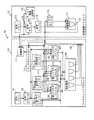
図1は、本発明の実施の形態1におけるマルチプロセッサシステム10の構成を示す。
マルチプロセッサシステム10は、マルチスレッドプロセッサ11と、拡張演算プロセッサ12とから構成されている。1.
1.1 Configuration FIG. 1 shows a configuration of a
The
マルチスレッドプロセッサ11は、最大N(Nは2以上の整数)個の命令流(N個のスレッド)を同時に独立して実行するプロセッサである。
拡張演算プロセッサ12は、マルチスレッドプロセッサ11からの制御により起動され、マルチスレッドプロセッサ11において実行中である1つのスレッドの指示による処理を実行するプロセッサである。The
The extended
以下、これらプロセッサの構成について説明する。
(1)マルチスレッドプロセッサ11の構成
マルチスレッドプロセッサ11は、図1にて示すように、命令メモリ101、命令デコーダ102、N個の命令バッファ(第1命令バッファ103、第2命令バッファ104、…、第N命令バッファ105)、N個のレジスタファイル(第1レジスタファイル106、第2レジスタファイル107、…、第Nレジスタファイル108)、演算器群109、ライトバックバス110、制御部111、及びコンテキストメモリ112から構成されている。The configuration of these processors will be described below.
(1) Configuration of
ここで、各命令バッファと各レジスタファイルは1対1に対応付けられ、N個の論理プロセッサを構成する。本実施の形態1においては、第1命令バッファ103と第1レジスタファイル106とから第1論理プロセッサ151が、第2命令バッファ104と第2レジスタファイル107とから第2論理プロセッサ152が、・・・、第N命令バッファ105と第Nレジスタファイル108とから第N論理プロセッサ153が、それぞれ構成されているものとする。 Here, each instruction buffer and each register file are associated with each other one to one, and constitute N logical processors. In the first embodiment, the first
マルチスレッドプロセッサ11は、複数のスレッドのうち最大N個のスレッドそれぞれを、異なる論理プロセッサへ割り付けることで、最大N個のスレッドが並列に実行すること実現する。
(1−1)命令メモリ101
命令メモリ101は、N個の論理プロセッサの何れかにより実行される複数の命令流(スレッド)を保持している。The
(1-1)
The
(1−2)命令デコーダ102
命令デコーダ102は、命令メモリ101から、実行対象である1以上のスレッドに属する命令を読み出し、デコードを行い、当該命令が属するスレッドが割り付けられた論理プロセッサの命令バッファに書き込む。
(1−3)第1命令バッファ103〜第N命令バッファ105
第i命令バッファ(iは1以上N以下の整数、以下同じ。)は、第i論理プロセッサに属し、当該第i論理プロセッサに割り付けられたスレッドに属する命令を受け取り、保持するものである。(1-2)
The
(1-3)
The i-th instruction buffer (i is an integer greater than or equal to 1 and less than or equal to N, and so on) receives and holds an instruction belonging to the i-th logical processor and belonging to a thread allocated to the i-th logical processor.
(1−4)第1レジスタファイル106〜第Nレジスタファイル108
第iレジスタファイルは、第i論理プロセッサに属し、第i命令バッファに保持された命令が実行される際に、読み出し及び書き込みの対象とされるデータを保持するレジスタ群である。
なお、レジスタファイルそれぞれの先頭アドレスは、0番から始まるものとする。(1-4)
The i-th register file is a register group that belongs to the i-th logical processor and holds data to be read and written when an instruction held in the i-th instruction buffer is executed.
It is assumed that the start address of each register file starts from 0.
(1−5)演算器群109
演算器群109は、加算器や乗算器などの複数の演算器を含む処理部であり、各論理プロセッサの処理を並列に行う。
(1−6)ライトバックバス110
ライトバックバス110は、演算器群109からの出力を第1レジスタファイル106〜第Nレジスタファイル108に書き戻すためのバスである。(1-5)
The
(1-6) Write-
The write back
(1−7)制御部111
制御部111は、図2にて示すように、スレッド制御部160と、スレッド情報記憶部161と、プロセッサ制御部162とから構成されている。
(1−7−1)スレッド制御部160
スレッド制御部160は、各スレッドのアクティブ化と非アクティブ化を管理するものである。ここで、アクティブなスレッドとは、第i論理プロセッサ、つまり第i命令バッファと第iレジスタファイルとを占有するリソースとして確保され、当該第i論理プロセッサ上で即座に実行できる状態にあるスレッドのことを指す。非アクティブなスレッドとは、どの論理プロセッサのいずれも占有するリソースとして確保されていないスレッドのことを指す。(1-7)
As shown in FIG. 2, the
(1-7-1)
The
スレッド制御部160は、スレッド切り替えの要因に基づいて、スレッドの非アクティブ化とアクティブ化を行う。ここで、スレッド切り替えの要因としては、アクティブなスレッドの実行時間が一定値に達したことを示す信号の受け取りや、他のハードウェアから入力されるイベント発生信号の受け取りや、特定の命令の実行が挙げられる。
スレッド制御部160は、図2にて示すように、退避部165及び復元部166を有しており、退避部165にてスレッドの非アクティブ化を行い、復元部166にてスレッドのアクティブ化を行う。The
As shown in FIG. 2, the
スレッド制御部160は、例えば、アクティブなスレッドの実行時間が一定値に達したことを示す信号を受け取ると、当該スレッドを非アクティブ化にする。具体的には、退避部165が、非アクティブ化対象と定められたスレッド(例えば、第2論理プロセッサ上で実行されていたスレッドとする)の命令メモリ101からの命令読み出しと、第2命令バッファ104からの命令発行を停止する。そして、退避部165は、第2レジスタファイル107の内容を、コンテキストメモリ112の定められた領域に退避する。 For example, when the
スレッド制御部160は、非アクティブ状態であるスレッドが再度実行対象となる場合、当該スレッドのアクティブ化を行う。具体的には、復元部166が、アクティブ化対象と定められたスレッド(ここでは第2論理プロセッサに割り付けられたスレッドとする)が使用するデータ(値)をコンテキストメモリ112から読み出し、第2レジスタファイル107に復帰する。その後、命令メモリ101からの対応する命令を読み出し、及び実行が開始される。コンテキストメモリ112上のデータの管理方法については後述する。 The
スレッド制御部160は、スレッドをアクティブ化及び非アクティブ化する際に、後述するスレッド情報テーブルT100の更新を行う。
(1−7−2)スレッド情報記憶部161
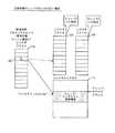
スレッド情報記憶部161は、個々のスレッドそれぞれの状態を管理するものであり、図3にて示すように、スレッド情報テーブルT100を有している。The
(1-7-2) Thread
The thread
スレッド情報テーブルT100は、スレッドID201、バリッド(Valid)フラグ202、論理プロセッサID203、スレッド状態フラグ204、及びベースアドレス205とからなる組(エントリ)を複数個(スレッドの個数分)記憶するための領域を有している。
スレッドID201は、各エントリに保持されるスレッドの情報が、どのスレッドに対応するものかを示すID番号である。The thread information table T100 is an area for storing a plurality (for the number of threads) of sets (entries) including a
The
バリッドフラグ202は、各エントリに保持されるスレッドの情報が有効なものであるかどうかを示すバリッドビットであり、"0"が無効な情報、"1"が有効な情報であることを示す。
論理プロセッサID203は、各エントリに保持されるスレッドの情報が、いずれの論理プロセッサ上で実行されているかを示すID番号である。例えば、論理プロセッサIDの値「00」は第1論理プロセッサ151を示し、「01」は第2論理プロセッサ152を示している。The
The
スレッド状態フラグ204は、各エントリに保持されるスレッド状態を示す情報である。"00"が非アクティブ状態、"01"がアクティブ状態、"10"または"11"が、アクティブ化または非アクティブ化のプロセス途中であることを示す。なお、スレッド状態フラグ204は、スレッド制御部160においてスレッドのアクティブから非アクティブへの状態変更、又は非アクティブからアクティブへの状態変更が行われる際に、スレッド制御部160にて更新される。例えば、スレッドのアクティブから非アクティブへの状態変更は退避部165が行い、非アクティブからアクティブへの状態変更は復元部166が行う。 The
ベースアドレス205は、コンテキストメモリ112内のアドレスを示し、当該アドレスを先頭位置として、エントリに保持されているスレッドIDに対応するスレッドに対するレジスタ値が格納されている
エントリ206は、スレッドIDが「00001」であるスレッド1が、有効なものであり、現在論理プロセッサID「00」とスレッド状態フラグにより第1論理プロセッサ151上で実行されていることを示している。The
また、エントリ208は、スレッドIDが「00011」であるスレッド3が、有効なものであり、現在非アクティブな状態にあることを示している。
なお、上述したように、スレッド情報テーブルT100は、スレッド制御部160により更新される。例えば、スレッド1がアクティブから非アクティブへと切り替わる場合、退避部165が、スレッド1、つまりスレッドID「00001」に対応するスレッド状態フラグが「00」からスレッド状態の切替中である旨を示す値「10」へ更新し、切替が完了するとスレッド状態フラグが「10」から非アクティブ状態である旨を示す値「01」へと更新される。また、逆に、非アクティブからアクティブへと切り替わる場合、復元部166が、スレッド1のスレッド状態フラグを「01」からスレッド状態の切替中である旨を示す値「11」へと更新し、スレッド状態の切替中である旨を示し、切替が完了するとスレッド状態フラグを「11」から「00」へと更新する。An
As described above, the thread information table T100 is updated by the
さらには、例えば、スレッド3が初めて論理プロセッサに割り当てられたとき(ここでは、第1論理プロセッサとする)、スレッド制御部160は、スレッド3に対応するエントリを追加する。この場合、エントリには、スレッドID「00011」、バリッドフラグ「1」、論理プロセッサID「00」、スレッド状態フラグ「01」、及びベースアドレス「0x4000000」が含まれる。 Further, for example, when the thread 3 is assigned to the logical processor for the first time (here, the first logical processor), the
(1−7−3)プロセッサ制御部162
プロセッサ制御部162は、実行対象である一のスレッドの命令により、拡張演算プロセッサ12へ処理依頼する。具体的には、プロセッサ制御部162は、演算器群109のうち、1の論理プロセッサに割り付けられたスレッドの命令を実行している演算器により実行された命令に従って、拡張演算プロセッサ12へ処理依頼する。また、プロセッサ制御部162は、処理を要求した当該一のスレッドを識別するスレッドIDをスレッド情報テーブルT100より取得して、取得したスレッドIDを拡張演算プロセッサへ出力する。(1-7-3)
The
その後、プロセッサ制御部162は、拡張演算プロセッサ12へ処理を要求したスレッドへの書き込みに係る書込要求を拡張演算プロセッサ12から受け取ると、拡張演算プロセッサ12から処理の依頼元であるスレッドのスレッドIDを取得する。ここで、書込要求とは、拡張演算プロセッサ12にて演算終了制御命令T110が実行されると、プロセッサ制御部162へ通知されるものである。なお、演算終了制御命令T110の詳細は後述する。 Thereafter, when the
プロセッサ制御部162は、スレッド情報テーブルT100を用いて、取得したスレッドIDを含むエントリ内のスレッド状態フラグを参照して、当該スレッドIDに対応するスレッドが実行対象として論理プロセッサが割り付けられているか否かを、つまりアクティブ状態であるか、非アクティブ状態であるかを判断する。
非アクティブ状態であると判断する場合には、プロセッサ制御部162は、拡張演算プロセッサ12から出力された書き込み対象のデータを、当該エントリ内のベースアドレスと拡張演算プロセッサ12にて指定されたレジスタとから特定されるコンテキストメモリ112内のアドレスへ書き込むよう制御する。なお、コンテキストメモリ112内への書き込みは、現時点でアクティブなスレッドの実行に影響を与えることなく、並列してハードウェアの処理により実現するものとする。このような動作により、アクティブなスレッドの実行の実行時間をうばって処理効率を低下させることを防ぐことができる。The
When determining that it is in an inactive state, the
アクティブ状態であると判断する場合には、プロセッサ制御部162は、当該スレッドIDに対応するスレッドが割り付けられた論理プロセッサのレジスタファイルに、拡張演算プロセッサ12から出力された書き込み対象のデータを、拡張演算プロセッサ12にて指定されたアドレスへ書き込むよう制御する。
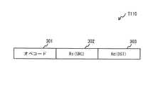
ここで、拡張演算プロセッサ12にて実行される演算終了制御命令T110のデータ構造について説明する。When determining that the state is the active state, the
Here, the data structure of the operation end control instruction T110 executed by the
図4は、本実施の形態1における演算終了制御命令T110のフォーマットであり、オペコード301、第1のオペランド302、第2のオペランド303とから構成されている。
オペコード301は、実行中の自スレッド(拡張演算プロセッサ12)を完了させるとともに、自スレッド(拡張演算プロセッサ12)のレジスタファイル内のデータを他スレッド(要求元のスレッド)のレジスタファイル内へ転送するようプロセッサに指示するコードである。FIG. 4 shows a format of the operation end control instruction T110 according to the first embodiment, which is composed of an
The
第1のオペランド302は、自スレッド(拡張演算プロセッサ)が使用するレジスタファイルのレジスタをデータ転送ソースとして指定するものである。
第2のオペランド303は、他スレッド(要求元のスレッド)が使用するレジスタファイルのレジスタをデータ転送デスティネーションとして指定するものである。なお、ここでは、第2のオペランド303は、レジスタをレジスタ番号で示すものとしている。The
The
要求元のスレッドがアクティブ状態である場合には、プロセッサ制御部162の制御により、第1のオペランド302にて示されるレジスタに記憶されているデータ(値)が、第2のオペランド303にて示される、論理プロセッサ内のレジスタファイルのレジスタへ書き込まれる。
要求元のスレッドがアクティブ状態である場合には、プロセッサ制御部162の制御により、先ず、スレッド情報テーブルT100を用いて、取得したスレッドIDが含まれるエントリから要求元のスレッドに対応付けられたベースアドレスが特定される。特定されたベースアドレスと第2のオペランド303にて示される値(Rd)とから、コンテキストメモリ112内において書き込むべきアドレスが特定される。例えば、ベースアドレスが4バイトで記憶されており、レジスタのサイズが各4バイトであった場合、数式"ベースアドレス+(第2のオペランド×4)"で特定される。第1のオペランド302にて示されるレジスタに記憶されているデータ(値)は、特定されたコンテキストメモリ112上のアドレスにて示されるレジスタへ書き込まれる。When the requesting thread is in the active state, the data (value) stored in the register indicated by the
When the request source thread is in the active state, first, the
図5及び図6は、本実施の形態1における演算終了制御命令T110が実行(発行)された場合の動作である。なお、ここでは、説明の都合上、マルチスレッドプロセッサ11は、レジスタファイル106、107の2つのみ有しており、スレッド1が拡張演算プロセッサ12へ処理依頼を行い、処理依頼時点では、スレッド1及びスレッド2それぞれが、レジスタファイル106、107それぞれに割り付けられているものとする。 FIG. 5 and FIG. 6 are operations when the operation end control instruction T110 in the first embodiment is executed (issued). Here, for convenience of explanation, the
拡張演算プロセッサ12においてスレッド完了命令が発行されると 結果を反映すべきスレッド(ここでは、スレッド1)、つまり拡張演算プロセッサ12に処理依頼を行ったスレッド1がアクティブであった場合、図5にて示すように、第1のオペランド302で指定された、レジスタファイル116内のレジスタRs402に記憶された値は、プロセッサ制御部162の制御により、処理依頼を行ったスレッド1が占有するレジスタファイル106内の、第2のオペランド303で指定されたレジスタRd404へ転送される(書き込まれる)。 When a thread completion instruction is issued in the extended
また、結果を反映すべきスレッド(ここでは、スレッド1)が、マルチスレッドプロセッサ11上で非アクティブである場合、例えば、レジスタファイル106はスレッド3に、レジスタファイル107はスレッド2に、それぞれ占有されている場合、図6にて示すように、プロセッサ制御部162の制御により、処理依頼を行ったスレッド1に対応付けられたコンテキストメモリ112内のベースアドレスと、第2のオペランド303で指定されたレジスタRd404とから上述した数式によりコンテキストメモリ112上の格納先のアドレスが特定され、第1のオペランド302で指定された、レジスタファイル116内のレジスタRs402に記憶された値は特定されたアドレスへ転送される(書き込まれる)。 Further, when the thread to reflect the result (here, thread 1) is inactive on the
(1−8)コンテキストメモリ112
コンテキストメモリ112は、非アクティブな状態にあるスレッドのレジスタセットの内容を退避するメモリであり、各スレッドそれぞれに対して異なる領域が割り当てられている。
ここでは、各スレッドそれぞれに対して、異なるアドレスをベースアドレスとして対応付けることで、領域の割り当てを実現している。(1-8)
The
Here, the area allocation is realized by associating each thread with a different address as a base address.
(2)拡張演算プロセッサ12の構成
拡張演算プロセッサ12は、図1にて示すように、命令メモリ113と、命令デコーダ114と、命令バッファ115と、レジスタファイル116と、演算器群117と、ライトバックバス118と、スレッド情報記憶部119を備えている。
(2−1)命令メモリ113
命令メモリ113は、拡張演算プロセッサ12において実行される命令を保持するメモリである。(2) Configuration of Extended
(2-1)
The
(2−2)命令デコーダ114
命令デコーダ114は、命令メモリ113から命令を読み出し、デコードを行い、命令バッファ115に書き込む処理部である。
命令デコーダ114は、デコードにより、演算終了制御命令T110を発行(実行)すると、発行した演算終了制御命令T110を命令バッファ115に書き込むとともに、マルチスレッドプロセッサ11のプロセッサ制御部162へ書込要求を通知する。(2-2)
The
When the
(2−3)命令バッファ115
命令バッファ115は、命令デコーダ114から命令を受け取り、保持する記憶部である。
レジスタファイル116は、命令バッファ115に保持された命令が実行される際に、読み出し及び書き込みの対象とされるデータを保持するレジスタ群である。(2-3)
The
The
なお、レジスタファイル116の先頭アドレスは0番から始まるものとする。
(2−4)演算器群117
演算器群117は、加算器や乗算器などの複数の演算器を含む処理部であり、命令バッファ115に保持されている命令を実行する。
演算器群117は、演算終了制御命令T110を命令バッファ115から読み出すと、読み出した演算終了制御命令T110に含まれる第1オペランド302にて示されるレジスタRsの値を読み出し、読み出した値と、当該値を第2オペランド302にて示されるレジスタRdへ書き込む旨の指示とをマルチスレッドプロセッサ11へライトバックバス118を介して出力する。なお、ライトバックバス118については後述する。It is assumed that the top address of the
(2-4)
The
When the operation end control instruction T110 is read from the
このとき、マルチスレッドプロセッサ11のプロセッサ制御部162は、拡張演算プロセッサ12からこれら情報が出力されると、先に行っている判断結果に基づいて書込先のアドレスを用いて特定された書き込み先へ、出力された値を書き込むよう制御する。
(2−5)ライトバックバス118
ライトバックバス118は、演算器群117からの出力をレジスタファイル116、第1レジスタファイル106〜第Nレジスタファイル108に書き戻すため、及びレジスタファイル116の内容を第1レジスタファイル106〜第Nレジスタファイル108若しくはコンテキストメモリ112へ書き込むためのバスである。At this time, when these pieces of information are output from the extended
(2-5) Write-
The write back
(2−6)スレッド情報記憶部119
スレッド情報記憶部119は、処理依頼の要求のあったスレッドを識別するスレッドIDを格納する領域を有している。
当該スレッド情報記憶部119への書き込みは、マルチスレッドプロセッサ11のプロセッサ制御部162にて行われる。(2-6) Thread
The thread
Writing to the thread
1.2 動作
ここでは、演算終了制御命令T110が実行された際のマルチプロセッサシステム10の動作について、図7にて示す流れ図を用いて説明する。
拡張演算プロセッサ12にて演算終了制御命令T110が発行されると、マルチスレッドプロセッサ11のプロセッサ制御部162は、反映すべきスレッドのID、つまり処理要求元のスレッドIDを、スレッド情報記憶部119から取得する(ステップS105)。1.2 Operation Here, the operation of the
When the operation end control instruction T110 is issued by the extended
プロセッサ制御部162は、スレッド情報テーブルT100の反映すべきスレッドIDの情報が記録されたエントリを読み出す(ステップS110)。
プロセッサ制御部162は、読み出したエントリに含まれるバリッドフラグ202の内容が1かどうかを判定する(ステップS115)。
1でないと判断する場合(ステップS115における「NO」、マルチプロセッサシステム10はエラー処理を行い(ステップS140)、処理を終了する。ここで、エラー処理は、例えば、レジスタファイル116に格納されている内容、命令バッファに保持されている命令、及び現在拡張演算プロセッサにて実行中の命令を破棄するものである。The
The
When determining that it is not 1 (“NO” in step S115, the
1であると判断する場合(ステップS115における「YES」)、プロセッサ制御部162は、読み出したエントリに含まれるスレッド状態フラグ204の内容が01かどうかを判定する(ステップS120)。
01であると判定する場合(ステップS120における「YES」)、プロセッサ制御部162は、読み出したエントリに含まれる論理プロセッサID203の内容が示す論理プロセッサが有するレジスタファイル中の、第2のオペランド303で示されたレジスタRdに、拡張演算プロセッサのレジスタファイル116中の、第1のオペランド302で示されたレジスタRsの内容を書き込むよう制御する(ステップS125)。When determining that the number is 1 (“YES” in step S115), the
When it is determined that it is 01 (“YES” in step S120), the
スレッド状態フラグ204の内容が01でないと判定する場合(ステップS125における「NO」)、プロセッサ制御部162は、スレッド状態フラグ204の内容が00かどうかを判定する(ステップS130)。
00であると判定する場合(ステップS130における「YES」)、プロセッサ制御部162は、読み出したエントリに含まれるベースアドレス205と、第2のオペランド303にて示されるレジスタRdとに基づいて算出されるコンテキストメモリ112上のアドレスに、拡張演算プロセッサのレジスタファイル116中の、第1のオペランド302で示されたレジスタRsの内容を転送し、スレッド完了命令の実行を完了する。When determining that the content of the
When it is determined that it is 00 (“YES” in step S130), the
スレッド状態フラグ204の内容が00でないと判定する場合(ステップS130における「NO」)、処理は、ステップS120に戻り、スレッドの状態が更新されるのを待つ。
1.3 実施の形態1のまとめ
図8は、本発明の実施の形態1における、複数のスレッド動作の様子である。なお、ここでは、論理プロセッサの個数を2つとしている。If it is determined that the content of the
1.3 Summary of
時間t0時点において、第1論理プロセッサ151ではスレッド2が、第2論理プロセッサ152ではスレッド1が、それぞれ実行されている(ステップS201、S202)。
時間t1において、スレッド1は拡張演算プロセッサ12へ処理依頼を行い、処理依頼を受けた拡張演算プロセッサ12は、スレッド1に対する処理を行う(ステップS203)。At time t0, thread 2 is executed in the first
At time t1, the
時間t2において、スレッド1が非アクティブとなり、スレッド3が第2論理プロセッサ151上で実行され(ステップS204)、スレッド3の実行中の時間t3において拡張演算プロセッサ12の処理が終了すると、スレッド1は非アクティブの状態であるので処理結果はコンテキストメモリへ書き込まれる。
その後、スレッド3の実行中の時間t4において、スレッド2にて拡張演算プロセッサ12へ処理依頼が行われると、拡張演算プロセッサ12は、スレッド1の処理から解放されている、つまりスレッド1に占有されていないので、拡張演算プロセッサ12はスレッド2に対する処理を行う(ステップS205)。At time t2, the
Thereafter, when a processing request is made to the extended
スレッド3の終了後の時間t5において、再度、スレッド1がアクティブになると、コンテキストメモリ112に拡張演算プロセッサ12による処理結果が反映されているので、スレッド1はコンテキストメモリ112内の保持されたデータを用いることで、処理を続行する(ステップS206)。
このように、本実施の形態1におけるマルチプロセッサシステム10は、スレッド1からの処理要求による拡張演算プロセッサ12での処理が終了した際、データの反映先となるスレッド1がアクティブでない場合でも、前述の演算終了制御命令T110によりコンテキストメモリ112上のスレッド1に対応付けられた領域に処理結果(データ)を反映し、即座に処理を完了させることができる。そのため、不要な待ち時間を発生させることなく、演算リソースを有効に使用することができる。When the
As described above, the
本実施の形態のマルチプロセッサによると、拡張演算プロセッサ12によるスレッドを終了させるとともに処理結果であるデータを他スレッド(依頼元のスレッド)に転送する際、当該他スレッドの状態に応じて、つまりデータ受け取り側のスレッドがアクティブであるか否かに応じて、データ転送先を適切に選択するので、スレッド間のデータの受け渡しを効率的に行うことができる。 According to the multiprocessor of the present embodiment, when the thread by the extended
2.実施の形態2
実施の形態2は、演算終了制御命令フィールドのデータ構造が実施の形態1のものとは異なる。
以下で命令フィールドの構成及び、動作フローチャートにおいて異なる点を説明する。なお、実施の形態1と同一の構成要素については、同一の符号を用いる。2. Embodiment 2
The second embodiment is different from the first embodiment in the data structure of the operation end control instruction field.
The difference in the structure of the instruction field and the operation flowchart will be described below. In addition, the same code | symbol is used about the component same as
2.1 演算終了制御命令T120について
図9は、本発明の実施の形態2における演算終了制御命令T120のフォーマットであり、オペコード901、第1のオペランド902、第2のオペランド903及び第3のオペランド904から構成されている。
オペコード901、第1のオペランド902、第2のオペランド903は、実施の形態1のオペコード301、第1のオペランド302、第2のオペランド303と同様であるので、ここでの説明は省略する。2.1 Regarding Operation Completion Control Instruction T120 FIG. 9 shows the format of the operation end control instruction T120 according to the second embodiment of the present invention. The
The
第3のオペランド904は、第2オペランド903で指定されるレジスタを持つスレッドID、つまり処理要求を行ったスレッドのスレッドIDを指定するものである。
2.2 構成
実施の形態2におけるマルチプロセッサシステム1000について説明する。
マルチプロセッサシステム1000は、図10にて示すように、マルチスレッドプロセッサ11aと拡張演算プロセッサ12aとから構成されている。The
2.2 Configuration
As shown in FIG. 10, the
実施の形態2では、命令デコーダ及びプロセッサ制御部が実施の形態1のものとは異なる。以下、図10にて示す実施の形態2における命令デコーダ114a及びプロセッサ制御部162aについて説明する。実施の形態1と同様の符号が付された構成要素については、実施の形態1にて説明しているので、ここでの説明は省略する。なお、図10にて示す第1論理プロセッサ151は、図示していないが実施の形態1と同様に、第1命令バッファ103及び第1レジスタファイル106を有している。また、第2論理プロセッサ152及び第N論理プロセッサ153も同様に、実施の形態1にて示す命令バッファ及びレジスタファイルを有している。スレッド制御部160についても、図示していないが実施の形態1と同様に、退避部165及び復元部166を有している。 In the second embodiment, the instruction decoder and the processor control unit are different from those in the first embodiment. Hereinafter, the
(1)命令デコーダ114a
命令デコーダ114aは、デコードにより、演算終了制御命令T120を発行すると、第3のオペランドからスレッドIDを取得する。命令デコーダ114aは、発行した演算終了制御命令T120を命令バッファ115に書き込むとともに、マルチスレッドプロセッサ11のプロセッサ制御部162aへ取得したスレッドIDを含む書込要求を通知する。(1)
When the
(2)プロセッサ制御部162a
プロセッサ制御部162aは、実施の形態1と同様に、実行対象である一のスレッドの命令により、拡張演算プロセッサ12へ処理依頼、及び処理依頼したスレッドのスレッドIDを拡張演算プロセッサ12へ通知する。このとき、スレッドIDは、スレッド情報記憶部119に書き込まれる。(2)
As in the first embodiment, the
その後、プロセッサ制御部162aは、拡張演算プロセッサ12からスレッドIDを含む書込要求を拡張演算プロセッサ12から受け取ると、受け取った書込要求に含まれるスレッドIDを含むエントリ内のスレッド状態フラグを参照して、当該スレッドIDに対応するスレッドが実行対象として論理プロセッサが割り付けられているか否かを、つまりアクティブ状態であるか、非アクティブ状態であるかを判断する。以降の動作については、実施の形態1と同様であるので、ここでの説明は省略する。 Thereafter, when receiving a write request including the thread ID from the extended
2.3 動作
以下、演算終了制御命令T120が実行された場合のマルチプロセッサシステム10の動作について、図7の変更点のみ説明する。
変更点は、ステップS105の動作を以下のように変更する。
拡張演算プロセッサ12にて演算終了制御命令T120が実行されると、演算終了制御命令T120に含まれるスレッドIDを取得するの取得は、第3のオペランド904から取得する。2.3 Operation Hereinafter, only the changes in FIG. 7 will be described regarding the operation of the
The change is that the operation in step S105 is changed as follows.
When the operation end control instruction T120 is executed by the extended
以降の動作は、図7にて示すステップS110からS140までの動作と同様であるので、ここでの説明は省略する。
2.4 実施の形態2のまとめ
実施の形態2では、アクティブであるか否かの判断対象となるスレッドを示すスレッドIDの取得方法が、実施の形態1とは異なるものであり、得られる効果は同様である。The subsequent operations are the same as the operations from step S110 to S140 shown in FIG. 7, and thus the description thereof is omitted here.
2.4 Summary of Second Embodiment In the second embodiment, the thread ID acquisition method indicating the thread to be determined whether or not it is active is different from that in the first embodiment, and the obtained effect Is the same.
3.実施の形態3
ここでは、実施の形態1にて示すマルチプロセッサシステム10を適用したシステムの具体例として、映像のデコード、エンコード処理に適用した場合について説明する。
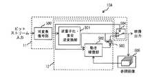
図11は、マルチプロセッサシステム10をデコード処理を行うデコーダ10Aに適用した場合を示すものである。3. Embodiment 3
Here, a case where the present invention is applied to video decoding and encoding processing will be described as a specific example of a system to which the
FIG. 11 shows a case where the
図12は、マルチプロセッサシステム10をエンコード処理を行うエンコーダ10Bに適用した場合を示すものである。
3.1 デコード処理に適用した場合
デコーダ10Aは、図11に示すように、可変長復号部500、逆量子化・直交逆変換部501、動き補償部502、加算部503、スイッチ504及び参照画像バッファ505から構成されている。FIG. 12 shows a case where the
3.1 When Applied to Decoding Processing As shown in FIG. 11, the
これら構成要素は、既知のものであるので、ここでの詳細な説明は省略し、これらの概略のみ説明する。
可変長復号部500は、可変長符号化された信号を復号(デコード)するものである。
逆量子化・直交逆変換部501は、可変長復号部500にて得られた量子化DCT係数に対して逆量子化及び逆周波数変換を行うものである。Since these components are already known, a detailed description thereof will be omitted, and only an outline thereof will be described.
The variable
The inverse quantization / orthogonal
動き補償部502は、動きベクトルを用いた画像データの生成を行うものである。
加算部503は、動き補償部502で得られた画像データと、逆量子化・直交逆変換部501で得られた画像のデータとを加算して、出力すべき画像データを生成するものである。
スイッチ504は、可変長復号部500にて得られた復号対象のピクチャの種別(P、I、Bピクチャ)に応じて、逆量子化・直交逆変換部501との接続、若しくは加算部503とのs接続を切り替えるものである。The
The adding
The
参照画像バッファ505は、参照画像を保持するためのものである。
ここで、図11にて示すように、実施の形態1にて示すマルチスレッドプロセッサ11が可変長復号部500とスイッチに係る処理を行い、拡張演算プロセッサ12が逆量子化・直交逆変換部501、動き補償部502及び加算部503に係る処理を行うように適用することで、デコード処理を行うデコーダに、実施の形態1にて示すマルチプロセッサシステム10を適用することができる。The
Here, as shown in FIG. 11, the
3.2 エンコード処理に適用した場合
エンコーダ10Bは、図12に示すように、減算部600、直交変換・量子化部601、可変長符号化部602、逆量子化・直交逆変換部603、加算部604、動き補償部605、動き検索部606及び参照画像バッファ607から構成されている。
これら構成要素は、既知のものであるので、ここでの詳細な説明は省略し、これらの概略のみ説明する。3.2 When Applying to Encoding Process As shown in FIG. 12, the
Since these components are already known, a detailed description thereof will be omitted, and only an outline thereof will be described.
減算部600は、符号化対象の画像データに対する予測誤差を算出するものである。
直交変換・量子化部601は、予測誤差に対して周波数変換及び量子化を行うものである。
可変長符号化部602は、量子化DCT係数及び動きベクトルを可変長符号化するものである。The
The orthogonal transform /
The variable
逆量子化・直交逆変換部603は、動き補償予測に用いるために量子化DCT係数に対して逆量子化及び逆周波数変換を行うものである。
加算部604は、動き補償部502で得られた画像データと、逆量子化・直交逆変換部501とから得られた画像のデータとの加算、及び加算結果の画像データに対してでブロッキングフィルタによりデブロッキングフィルタ処理を施して、参照画像として参照画像バッファ607で保持するための画像データを生成するものである。The inverse quantization / orthogonal
The
動き補償部605は、動きベクトルを用いた画像データの生成を行うものである。
動き検索部606は、動き補償予測を行い動きベクトルを検出するものである。
参照画像バッファ607は、参照画像を保持するためのものである。
ここで、図12にて示すように、実施の形態1にて示すマルチスレッドプロセッサ11が可変長符号化部602に係る処理を行い、拡張演算プロセッサ12が減算部600、直交変換・量子化部601、逆量子化・直交逆変換部603、加算部604、動き補償部605及び動き検索部606に係る処理を行うように適用することで、エンコーダ10Bに、実施の形態1にて示すマルチプロセッサシステム10を適用することができる。The
The
The
Here, as shown in FIG. 12, the
3.3 実施の形態3のまとめ
H.264等の規格を用いて圧縮された映像信号をデコードするには、上述したように、ビットストリームの解析、可変長符号化された信号のデコード処理、逆量子化、逆周波数変換、動き補償、デブロックフィルタ処理が必要となる。
これらの処理のうち、ビットストリームの解析、可変長符号化された信号のデコード処理といった逐次系処理は一般的なプロセッサ(マルチスレッドプロセッサ)において、現実的な動作周波数での処理が可能である。一方、画素系処理である逆量子化、逆周波数変換、動き補償、デブロックフィルタ処理に関しては、複数の画素に対して同時に演算を行うデータ並列型のプロセッサ(拡張演算プロセッサ)が適している。3.3 Summary of Embodiment 3 In order to decode a video signal compressed using a standard such as H.264, as described above, analysis of a bit stream, decoding processing of a variable-length encoded signal, inverse quantization, inverse frequency conversion, motion compensation, Deblock filtering is required.
Among these processes, sequential processing such as analysis of a bit stream and decoding of a variable-length encoded signal can be performed at a practical operating frequency in a general processor (multi-thread processor). On the other hand, with respect to inverse quantization, inverse frequency conversion, motion compensation, and deblocking filter processing, which are pixel processing, a data parallel type processor (extended arithmetic processor) that performs operations on a plurality of pixels simultaneously is suitable.
データ並列型のプロセッサは、レジスタセットや演算器により幅広いデータ幅を必要とするので、独立した拡張演算プロセッサとすることで、逐次系処理を行うプロセッサのリソースを増加させずに効率的なプロセッサを実装することができる。
本実施例では、逐次系処理をマルチスレッドプロセッサ、画素系処理を前記拡張演算プロセッサとすることで、回路規模の増加を抑えつつ、拡張演算プロセッサの使用効率を向上させたリアルタイム映像処理システムを構築することができる。Since a data parallel type processor requires a wide data width depending on a register set and an arithmetic unit, an efficient processor can be obtained without increasing the resources of a processor that performs sequential processing by using an independent extended arithmetic processor. Can be implemented.
In the present embodiment, a real-time video processing system is constructed in which the use efficiency of the extended arithmetic processor is improved while suppressing the increase in circuit scale by using a multi-thread processor for sequential processing and the extended arithmetic processor for pixel processing. can do.
4.変形例
上記に説明した各実施の形態は、本発明の実施の一例であり、本発明はこの実施の形態に何ら限定されるものではなく、その旨を逸脱しない範囲において種々なる態様で実施し得るものである。例えば、以下のような場合も本発明に含まれる。
(1)上記実施の形態において、拡張演算プロセッサ12の各構成要素113〜117は、マルチスレッドプロセッサ11の構成要素と共有しても良い。4). Each embodiment described above is an example of the implementation of the present invention, and the present invention is not limited to this embodiment at all, and can be implemented in various modes without departing from the scope of the present invention. To get. For example, the present invention includes the following cases.
(1) In the above embodiment, each of the
(2)上記実施の形態において、拡張演算プロセッサ12は、マルチスレッドプロセッサ11とは独立して命令を保持しているとしたが、これに限定されない。
拡張演算プロセッサ12は、供給元のスレッド、つまり論理プロセッサによる指示にて動作するようにしても良い。
(3)上記実施の形態において、書込要求を、命令デコーダ114がプロセッサ制御部162へ通知するものとしたが、これに限定されない。(2) In the above embodiment, the extended
The extended
(3) In the above embodiment, the
演算器群117が、演算終了制御命令T110に基づく処理を行った後、マルチスレッドプロセッサ11へデータを出力する際に、書込要求をプロセッサ制御部162へ通知するとしてもよい。
また、演算器群117が、演算終了制御命令T120に基づく処理を行った場合も同様に、マルチスレッドプロセッサ11へデータを出力する際に、スレッドIDを含む書込要求をプロセッサ制御部162へ通知することで実現できる。When the
Similarly, when the
(4)上記実施の形態において、演算終了制御命令T110は、第1のオペランドRSと第2のオペランドRdとからなる組を1組含むとしたが、これに限定されない。演算終了制御命令T110内に、この組を複数個含むとしてもよい。
また、演算終了制御命令T120においても同様に、第1のオペランドRSと第2のオペランドRdとからなる組を複数個含むとしてもよい。(4) In the above embodiment, the calculation end control instruction T110 includes one set including the first operand RS and the second operand Rd. However, the present invention is not limited to this. A plurality of sets may be included in the operation end control instruction T110.
Similarly, the operation end control instruction T120 may include a plurality of sets of the first operand RS and the second operand Rd.
(5)上記実施の形態において、演算終了制御命令T110が実行された際に、演算器群117は、演算終了制御命令T110に含まれる第1オペランドにて示されるレジスタRsに格納された値(処理結果)と、当該値を第2オペランドにて示されるレジスタRdへ書き込む旨の指示とをマルチスレッドプロセッサ11へ出力したが、これに限定されない。 (5) In the above embodiment, when the operation end control instruction T110 is executed, the
演算器群117は、演算終了制御命令T110に含まれる第1オペランドにて示されるレジスタRsと、当該値を第2オペランドにて示されるレジスタRdへ書き込む旨の指示とをマルチスレッドプロセッサ11へ出力してもよい。
このとき、プロセッサ制御部162は、受け取った指示に含まれるレジスタRsにて示されるアドレスに基づいて、レジスタファイル116から処理結果を読み出し、読み出した処理結果を、レジスタRdを用いて要求元のスレッドの状態に応じた書き込み先を特定する。The
At this time, the
また、実施の形態2においては、上記の指示にさらに、第3のオペランドにて示される要求元のスレッドIDを含めることで、実現できる。
(6)上記実施の形態において、スレッドが初めて論理プロセッサに割り当てられたときに、スレッド制御部160が当該スレッドに対応するエントリを追加するとしたが、これに限定されない。Further, in the second embodiment, this can be realized by including the thread ID of the request source indicated by the third operand in the above instruction.
(6) In the above embodiment, when a thread is first assigned to a logical processor, the
例えば、各スレッドに割り当てられる論理プロセッサを予め対応付けておいてもよい。この場合、スレッド情報テーブルT100には、スレッド毎のエントリが予め登録されており、エントリに含まれるバリッドフラグ及びスレッド状態フラグそれぞれの初期値を「0」及び「00」とし、対応するスレッドの状態に応じて、スレッド制御部160がこれらフラグの値を更新する。 For example, a logical processor assigned to each thread may be associated in advance. In this case, an entry for each thread is registered in the thread information table T100 in advance, and the initial values of the valid flag and thread state flag included in the entry are set to “0” and “00”, and the state of the corresponding thread is set. Accordingly, the
(8)上記実施の形態において、マルチスレッドプロセッサ11は、1つのプロセッサであり、当該プロセッサ内において複数の論理プロセッサが構成しているとしたが、これに限定されない。
マルチスレッドプロセッサ11内において複数のプロセッサエレメントが構成されているとしてもよい。(8) In the above embodiment, the
A plurality of processor elements may be configured in the
(9)上記実施の形態において、拡張演算プロセッサ12は、処理要求元のスレッドに対する処理が完了した時点で、書き込みに係る要求をマルチスレッドプロセッサ11へ通知したが、これに限定されない。
処理途中において、書き込みに係る要求をマルチスレッドプロセッサ11へ通知してもよい。(9) In the above embodiment, the extended
In the middle of processing, a request for writing may be notified to the
(10)上記実施の形態において、レジスタのサイズを4バイトとしたが、これに限定されない。
レジスタのサイズは他の値であってもよい。例えば、16バイトである。この場合、上記にて示した数式は、"ベースアドレス+(第2のオペランド×16)"と変更される。
(11)上記実施の形態において、各論理プロセッサは、並列に実行されるものとしたが、これに限定されない。(10) In the above embodiment, the register size is 4 bytes. However, the present invention is not limited to this.
The register size may be other values. For example, 16 bytes. In this case, the mathematical formula shown above is changed to “base address + (second operand × 16)”.
(11) In the above embodiment, each logical processor is executed in parallel. However, the present invention is not limited to this.
例えば、各論理プロセッサのうち一の論理プロセッサのみに演算器群109が割り当てられ、タイムスライスにより、この割り当てを変更するという擬似的な並列による処理であってもよい。
なお、このような擬似的な並列処理も、本発明における並列処理の概念に含めるものとする。For example, the
Such pseudo parallel processing is also included in the concept of parallel processing in the present invention.
(12)本発明は、上記に示す方法であるとしてもよい。また、これらの方法をコンピュータにより実現するコンピュータプログラムであるとしてもよいし、前記コンピュータプログラムからなるデジタル信号であるとしてもよい。
また、本発明は、前記コンピュータプログラムまたは前記デジタル信号をコンピュータ読み取り可能な記録媒体、例えば、フレキシブルディスク、ハードディスク、CD−ROM、MO、DVD、DVD−ROM、DVD−RAM、BD(Blu−ray Disc)、半導体メモリなどに記録したものとしてもよい。また、これらの記録媒体に記録されている前記デジタル信号であるとしてもよい。(12) The present invention may be the method described above. Further, the present invention may be a computer program that realizes these methods by a computer, or may be a digital signal composed of the computer program.
The present invention also provides a computer-readable recording medium such as a flexible disk, hard disk, CD-ROM, MO, DVD, DVD-ROM, DVD-RAM, BD (Blu-ray Disc). ), Recorded in a semiconductor memory or the like. The digital signal may be recorded on these recording media.
(13)上記実施の形態及び上記変形例をそれぞれ組み合わせるとしてもよい。 (13) The above embodiment and the above modifications may be combined.
本発明に係るマルチプロセッサシステムは、柔軟で高性能な演算処理を実現する機能を有するので、DVDレコーダやデジタルTV等の映像や音声のメディア処理を行うマルチプロセッサシステムに適用できる。
本発明に係るマルチプロセッサシステムを製造、販売する産業において、経営的、つまり反復的かつ継続的に利用されうる。Since the multiprocessor system according to the present invention has a function for realizing flexible and high-performance arithmetic processing, it can be applied to a multiprocessor system that performs media processing of video and audio such as a DVD recorder and a digital TV.
In the industry for manufacturing and selling the multiprocessor system according to the present invention, it can be used for management, that is, repetitively and continuously.
10 マルチプロセッサシステム
11 マルチスレッドプロセッサ
12 拡張演算プロセッサ
101 命令メモリ
102 命令デコーダ
103 第1命令バッファ
104 第2命令バッファ
105 第N命令バッファ
106 第1レジスタファイル
107 第2レジスタファイル
108 第Nレジスタファイル
109 演算器群
110 ライトバックバス
111 制御部
112 コンテキストメモリ
113 命令メモリ
114 命令デコーダ
115 命令バッファ
116 レジスタファイル
117 演算器群
118 ライトバックバス
119 スレッド情報記憶部
160 スレッド制御部
161 スレッド情報記憶部
162 プロセッサ制御部
165 退避部
166 復元部DESCRIPTION OF
Claims (9)
Translated fromJapanese前記第2プロセッサは、前記第1プロセッサから処理依頼がなされると、前記第1プロセッサの指示に応じた処理を行い、当該処理結果の値の書き込み要求を前記第1プロセッサへ通知し、
前記第1プロセッサは、
前記複数のスレッド毎に割り当てられた領域を有する記憶手段と、
実行対象である各スレッドについて、当該スレッドが実行対象から非実行対象となる場合に当該スレッドに割り付けられたレジスタファイル内の値を前記記憶手段において割り当てられた領域に保存する第1の制御手段と、
実行対象の一のスレッドに含まれる命令に応じて前記第2プロセッサに処理依頼をし、前記第2プロセッサから当該スレッドに対する処理結果の値の書き込み要求を受け付けると、現時点で当該スレッドが実行対象であるか否かを判断し、実行対象でないと判断する場合には前記記憶手段において当該スレッドに割り当てられた領域の一部に前記処理結果の値を書き込むよう制御する第2の制御手段と、
スレッドが非実行対象から再度実行対象となる場合に、当該スレッドに割り当てられた領域内の値を再度割り付けられたレジスタファイルへ復元する第3の制御手段とを備える
ことを特徴とするマルチプロセッサ。A different register file is allocated to each of a predetermined number of threads to be executed among a plurality of threads, and a process according to an instruction from the first processor is performed in parallel with the processes of the allocated threads. A multiprocessor comprising a second processor,
When a processing request is made from the first processor, the second processor performs processing according to an instruction from the first processor, notifies the first processor of a write request for a value of the processing result,
The first processor is
Storage means having an area allocated for each of the plurality of threads;
A first control unit that stores, for each thread that is an execution target, a value in a register file that is allocated to the thread when the thread is changed from an execution target to a non-execution target in an area allocated in the storage unit; ,
When a processing request is made to the second processor in response to an instruction included in one thread to be executed, and a write request for a processing result value for the thread is received from the second processor, the thread is currently the execution target. A second control means for controlling whether or not to write the value of the processing result in a part of an area allocated to the thread in the storage means when determining whether or not the target is not an execution target;
A multiprocessor comprising: a third control unit that restores a value in an area allocated to a thread to a reassigned register file when the thread is changed from a non-execution target to an execution target.
前記第2プロセッサは、前記スレッド識別子を、前記第1プロセッサから受け取って記憶し、
前記第2の制御手段は、前記書き込み要求を受け付けると、前記第2プロセッサにて記憶されている前記スレッド識別子を取得し、取得したスレッド識別子に基づいて前記判断の対象となるスレッドを特定する
ことを特徴とする請求項1に記載のマルチプロセッサ。The second control means outputs a thread identifier for identifying the one thread to the second processor at the time of processing request to the second processor,
The second processor receives and stores the thread identifier from the first processor;
When the second control unit receives the write request, the second control unit acquires the thread identifier stored in the second processor, and specifies the thread to be determined based on the acquired thread identifier. The multiprocessor according to claim 1.
前記第2プロセッサは、
前記処理結果の値を転送する旨を指示するオペコードと、前記処理結果の値が格納されている第2プロセッサ内のレジスタファイル内のレジスタを指定する第1のオペランドと、転送先のレジスタファイル内のレジスタを指定する第2のオペランドとを含む命令を実行すると、前記書き込み要求を前記第1プロセッサへ通知し、
前記第2の制御手段は、
前記判断により前記スレッド識別子にて示されるスレッドが非実行対象であると判断する場合には、前記スレッド識別子にて示されるスレッドに割り当てられた領域の先頭アドレスと前記第2プロセッサにて実行された命令に含まれる前記第2のオペランドにて示されるレジスタとから前記記憶手段における書き込み位置を特定し、特定した位置に前記第2プロセッサにて実行された命令に含まれる前記第1のオペランドにて示されるレジスタに格納されている前記処理結果の値を書き込むよう制御し、
前記判断により前記スレッド識別子にて示されるスレッドが実行対象であると判断する場合には、対応するレジスタ識別子が示すレジスタファイルにおいて前記第2のオペランドにて示されるレジスタへ、前記第2プロセッサにて実行された命令に含まれる前記第1のオペランドにて示されるレジスタに格納されている前記処理結果の値を書き込むよう制御する
ことを特徴とする請求項2に記載のマルチプロセッサ。The second control means stores a head address of each area allocated to each thread in the storage means,
The second processor is
An opcode for instructing transfer of the processing result value, a first operand designating a register in a register file in the second processor in which the processing result value is stored, and a transfer destination register file When the instruction including the second operand designating the register of is executed, the write request is notified to the first processor,
The second control means includes
When it is determined by the determination that the thread indicated by the thread identifier is a non-execution target, the start address of the area allocated to the thread indicated by the thread identifier and the second processor executed The write position in the storage means is specified from the register indicated by the second operand included in the instruction, and the first operand included in the instruction executed by the second processor at the specified position Control to write the value of the processing result stored in the indicated register;
If it is determined by the determination that the thread indicated by the thread identifier is an execution target, the second processor moves to the register indicated by the second operand in the register file indicated by the corresponding register identifier. The multiprocessor according to claim 2, wherein control is performed to write a value of the processing result stored in a register indicated by the first operand included in the executed instruction.
前記複数のスレッドそれぞれに対して、当該スレッドが実行対象であるか非実行対象であるかを示すフラグと、当該スレッドが実行対象となる場合において割り付けられるレジスタファイルを識別するレジスタ識別子とを対応付けて記憶し、
前記判断により前記スレッド識別子にて示されるスレッドに対応するフラグを用いて前記判断を行う
ことを特徴とする請求項3に記載のマルチプロセッサ。The second control means includes
For each of the plurality of threads, a flag indicating whether the thread is an execution target or a non-execution target is associated with a register identifier for identifying a register file to be allocated when the thread is an execution target. Remember,
The multiprocessor according to claim 3, wherein the determination is performed using a flag corresponding to the thread indicated by the thread identifier.
前記第2プロセッサは、前記第1プロセッサから前記スレッド識別子を受け取って記憶し、前記書き込み要求を通知する際に、前記スレッド識別子を前記書き込み要求に含めて前記第1プロセッサへ通知し、
前記第2の制御手段は、前記書き込み要求を受け付けると、受け取った前記書き込み要求に含まれるスレッド識別子に基づいて前記判断の対象となるスレッドを特定する
ことを特徴とする請求項1に記載のマルチプロセッサ。The second control means outputs a thread identifier for identifying the one thread to the second processor at the time of processing request to the second processor,
The second processor receivesand storesthe thread identifier from the first processor, when notifying the write request, and notifies including the thread identifier to the write request to the first processor,
2. The multi control unit according to claim 1, wherein, when the second control unit receives the write request, the second control unit identifies a thread to be determined based on a thread identifier included in the received write request. Processor.
前記第2プロセッサは、前記処理結果の値を転送する旨を指示するオペコードと、前記処理結果の値が格納されている第2プロセッサ内のレジスタファイル内のレジスタを指定する第1のオペランドと、転送先のレジスタファイル内のレジスタを指定する第2のオペランドと、処理を要求したスレッドを識別するスレッド識別子とを含む命令を実行すると、前記スレッド識別子を含む前記書き込み要求を前記第1プロセッサへ通知し、
前記第2の制御手段は、
前記判断により前記スレッド識別子にて示されるスレッドが非実行対象であると判断する場合には、前記スレッド識別子にて示されるスレッドに割り当てられた領域の先頭アドレスと前記第2プロセッサにて実行された命令に含まれる前記第2のオペランドにて示されるレジスタとから前記記憶手段における書き込み位置を特定し、特定した位置に前記第2プロセッサにて実行された命令に含まれる前記第1のオペランドにて示されるレジスタに格納されている前記処理結果の値を書き込むよう制御する
ことを特徴とする請求項5に記載のマルチプロセッサ。The second control means stores a head address of each area allocated to each thread in the storage means,
The second processor, an opcode for instructing to transfer the value of the processing result; a first operand for designating a register in a register file in the second processor in which the value of the processing result is stored; When an instruction including a second operand designating a register in a transfer destination register file and a thread identifier for identifying a thread that has requested processing is executed, the write request including the thread identifier is notified to the first processor. And
The second control means includes
When it is determined by the determination that the thread indicated by the thread identifier is a non-execution target, the start address of the area allocated to the thread indicated by the thread identifier and the second processor executed The write position in the storage means is specified from the register indicated by the second operand included in the instruction, and the first operand included in the instruction executed by the second processor at the specified position The multiprocessor according to claim 5, wherein control is performed to write a value of the processing result stored in the indicated register.
前記第1プロセッサにて処理される各スレッドは、前記デコード処理のうち可変長符号化された信号のデコードを行い、
前記第2プロセッサにて行われる前記指示に応じた処理は、前記デコード処理のうち逆量子化、逆周波数変換、動き補償及び画像データの加算に係る処理である
ことを特徴とする請求項1に記載のマルチプロセッサ。The multiprocessor is a processing system for performing video decoding processing,
Each thread processed by the first processor decodes a variable-length encoded signal in the decoding process,
The process according to the instruction performed by the second processor is a process related to dequantization, inverse frequency conversion, motion compensation, and addition of image data in the decoding process. The described multiprocessor.
前記第1プロセッサにて処理される各スレッドは、前記エンコード処理のうち画像データに対する可変長符号化に係る処理を行い、
前記第2プロセッサにて行われる前記指示に応じた処理は、前記エンコード処理のうち符号化対象の画像データに対する予測誤差、量子化、周波数変換、動き補償、動き検索、逆量子化、逆周波数変換及び画像データの加算に係る処理である
ことを特徴とする請求項1に記載のマルチプロセッサ。The multiprocessor is a processing system for performing video encoding processing,
Each thread processed by the first processor performs processing related to variable-length encoding for image data in the encoding processing,
The processing according to the instruction performed by the second processor includes prediction error, quantization, frequency conversion, motion compensation, motion search, inverse quantization, and inverse frequency conversion for the image data to be encoded in the encoding process. The multiprocessor according to claim 1, wherein the processing is related to addition of image data.
前記第2プロセッサは、前記第1プロセッサから処理依頼がなされると、前記第1プロセッサの指示に応じた処理を行い、当該処理結果の値の書き込み要求を前記第1プロセッサへ通知し、
前記第1プロセッサは、前記複数のスレッド毎に割り当てられた領域を有する記憶手段を備え、
前記処理方法は、
実行対象である各スレッドについて、当該スレッドが実行対象から非実行対象となる場合に当該スレッドに割り付けられたレジスタファイル内の値を前記記憶手段において割り当てられた領域に保存する第1の制御ステップと、
実行対象の一のスレッドに含まれる命令に応じて前記第2プロセッサに処理依頼をし、前記第2プロセッサから当該スレッドに対する処理結果の値の書き込み要求を受け付けると、現時点で当該スレッドが実行対象であるか否かを判断し、実行対象でないと判断する場合には前記記憶手段において当該スレッドに割り当てられた領域の一部に前記処理結果の値を書き込むよう制御する第2の制御ステップと、
スレッドが非実行対象から再度実行対象となる場合に、当該スレッドに割り当てられた領域内の値を再度割り付けられたレジスタファイルへ復元する第3の制御ステップとを含む
ことを特徴とする処理方法。A different register file is allocated to each of a predetermined number of threads to be executed among a plurality of threads, and a process according to an instruction from the first processor is performed in parallel with the processes of the allocated threads. A processing method used in a multiprocessor comprising a second processor,
When a processing request is made from the first processor, the second processor performs processing according to an instruction from the first processor, notifies the first processor of a write request for a value of the processing result,
The first processor includes storage means having an area allocated for each of the plurality of threads.
The processing method is as follows:
A first control step that stores, for each thread to be executed, a value in a register file assigned to the thread when the thread is changed from an execution target to a non-execution target in an area allocated in the storage unit; ,
When a processing request is made to the second processor in response to an instruction included in one thread to be executed, and a write request for a processing result value for the thread is received from the second processor, the thread is currently the execution target. A second control step for controlling whether to write the value of the processing result in a part of the area allocated to the thread in the storage means when determining whether or not it is not an execution target;
And a third control step of restoring a value in an area assigned to the thread to a reassigned register file when the thread is changed from a non-execution target to an execution target.
Priority Applications (1)
| Application Number | Priority Date | Filing Date | Title |
|---|---|---|---|
| JP2010503153AJP5379122B2 (en) | 2008-06-19 | 2009-06-16 | Multiprocessor |
Applications Claiming Priority (4)
| Application Number | Priority Date | Filing Date | Title |
|---|---|---|---|
| JP2008159964 | 2008-06-19 | ||
| JP2008159964 | 2008-06-19 | ||
| PCT/JP2009/002735WO2009153977A1 (en) | 2008-06-19 | 2009-06-16 | Multiprocessor |
| JP2010503153AJP5379122B2 (en) | 2008-06-19 | 2009-06-16 | Multiprocessor |
Publications (2)
| Publication Number | Publication Date |
|---|---|
| JPWO2009153977A1 JPWO2009153977A1 (en) | 2011-11-24 |
| JP5379122B2true JP5379122B2 (en) | 2013-12-25 |
Family
ID=41433895
Family Applications (1)
| Application Number | Title | Priority Date | Filing Date |
|---|---|---|---|
| JP2010503153AExpired - Fee RelatedJP5379122B2 (en) | 2008-06-19 | 2009-06-16 | Multiprocessor |
Country Status (4)
| Country | Link |
|---|---|
| US (1) | US8433884B2 (en) |
| JP (1) | JP5379122B2 (en) |
| CN (1) | CN102067088A (en) |
| WO (1) | WO2009153977A1 (en) |
Cited By (1)
| Publication number | Priority date | Publication date | Assignee | Title |
|---|---|---|---|---|
| KR20190044569A (en)* | 2017-10-20 | 2019-04-30 | 그래프코어 리미티드 | Combining states of multiple threads in a multi-threaded processor |
Families Citing this family (15)
| Publication number | Priority date | Publication date | Assignee | Title |
|---|---|---|---|---|
| JP5336423B2 (en)* | 2010-05-14 | 2013-11-06 | パナソニック株式会社 | Computer system |
| GB2481819B (en)* | 2010-07-07 | 2018-03-07 | Advanced Risc Mach Ltd | Switching between dedicated function hardware and use of a software routine to generate result data |
| TWI439925B (en)* | 2011-12-01 | 2014-06-01 | Inst Information Industry | Embedded systems and methods for threads and buffer management thereof |
| US9021237B2 (en)* | 2011-12-20 | 2015-04-28 | International Business Machines Corporation | Low latency variable transfer network communicating variable written to source processing core variable register allocated to destination thread to destination processing core variable register allocated to source thread |
| US9069598B2 (en)* | 2012-01-06 | 2015-06-30 | International Business Machines Corporation | Providing logical partions with hardware-thread specific information reflective of exclusive use of a processor core |
| US20130339681A1 (en)* | 2012-06-18 | 2013-12-19 | Freescale Semiconductor, Inc. | Temporal Multithreading |
| US9582287B2 (en)* | 2012-09-27 | 2017-02-28 | Intel Corporation | Processor having multiple cores, shared core extension logic, and shared core extension utilization instructions |
| US9430411B2 (en) | 2013-11-13 | 2016-08-30 | Sandisk Technologies Llc | Method and system for communicating with non-volatile memory |
| US9390033B2 (en) | 2013-11-13 | 2016-07-12 | Sandisk Technologies Llc | Method and system for communicating with non-volatile memory via multiple data paths |
| US9377968B2 (en) | 2013-11-13 | 2016-06-28 | Sandisk Technologies Llc | Method and system for using templates to communicate with non-volatile memory |
| JP6232127B2 (en)* | 2014-04-22 | 2017-11-15 | 株式会社日立製作所 | Shared resource update device and shared resource update method |
| US10990445B2 (en)* | 2017-08-04 | 2021-04-27 | Apple Inc. | Hardware resource allocation system for allocating resources to threads |
| US11269396B2 (en)* | 2018-09-28 | 2022-03-08 | Intel Corporation | Per-core operating voltage and/or operating frequency determination based on effective core utilization |
| WO2022016481A1 (en) | 2020-07-24 | 2022-01-27 | Citrix Systems, Inc. | Auto termination of applications based on application and user activity |
| US11861403B2 (en)* | 2020-10-15 | 2024-01-02 | Nxp Usa, Inc. | Method and system for accelerator thread management |
Citations (3)
| Publication number | Priority date | Publication date | Assignee | Title |
|---|---|---|---|---|
| JPH04195664A (en)* | 1990-11-28 | 1992-07-15 | Hitachi Ltd | multiprocessor system |
| JP2002163121A (en)* | 2000-11-22 | 2002-06-07 | Toshiba Corp | Virtual multi-thread processor and thread execution method |
| JP2006350531A (en)* | 2005-06-14 | 2006-12-28 | Sony Computer Entertainment Inc | Information processor, process control method and computer program |
Family Cites Families (22)
| Publication number | Priority date | Publication date | Assignee | Title |
|---|---|---|---|---|
| US6223208B1 (en)* | 1997-10-03 | 2001-04-24 | International Business Machines Corporation | Moving data in and out of processor units using idle register/storage functional units |
| US20030225816A1 (en)* | 2002-06-03 | 2003-12-04 | Morrow Michael W. | Architecture to support multiple concurrent threads of execution on an arm-compatible processor |
| US7376954B2 (en) | 2003-08-28 | 2008-05-20 | Mips Technologies, Inc. | Mechanisms for assuring quality of service for programs executing on a multithreaded processor |
| US7849297B2 (en) | 2003-08-28 | 2010-12-07 | Mips Technologies, Inc. | Software emulation of directed exceptions in a multithreading processor |
| EP1660993B1 (en) | 2003-08-28 | 2008-11-19 | MIPS Technologies, Inc. | Integrated mechanism for suspension and deallocation of computational threads of execution in a processor |
| US20050050305A1 (en) | 2003-08-28 | 2005-03-03 | Kissell Kevin D. | Integrated mechanism for suspension and deallocation of computational threads of execution in a processor |
| US7711931B2 (en) | 2003-08-28 | 2010-05-04 | Mips Technologies, Inc. | Synchronized storage providing multiple synchronization semantics |
| US7418585B2 (en) | 2003-08-28 | 2008-08-26 | Mips Technologies, Inc. | Symmetric multiprocessor operating system for execution on non-independent lightweight thread contexts |
| US7836450B2 (en) | 2003-08-28 | 2010-11-16 | Mips Technologies, Inc. | Symmetric multiprocessor operating system for execution on non-independent lightweight thread contexts |
| US9032404B2 (en) | 2003-08-28 | 2015-05-12 | Mips Technologies, Inc. | Preemptive multitasking employing software emulation of directed exceptions in a multithreading processor |
| US7870553B2 (en) | 2003-08-28 | 2011-01-11 | Mips Technologies, Inc. | Symmetric multiprocessor operating system for execution on non-independent lightweight thread contexts |
| US7594089B2 (en) | 2003-08-28 | 2009-09-22 | Mips Technologies, Inc. | Smart memory based synchronization controller for a multi-threaded multiprocessor SoC |
| JP4195664B2 (en) | 2004-01-22 | 2008-12-10 | 日立建機株式会社 | Replacement method of buried pipe and pipe inner peripheral wall processing device for buried pipe replacement |
| JP2006099332A (en) | 2004-09-29 | 2006-04-13 | Sony Corp | Information processor, process control method and computer program |
| JP5175517B2 (en) | 2005-04-12 | 2013-04-03 | パナソニック株式会社 | Processor |
| US7926055B2 (en) | 2005-04-12 | 2011-04-12 | Panasonic Corporation | Processor capable of reconfiguring a logical circuit |
| US7281118B2 (en)* | 2005-08-05 | 2007-10-09 | International Business Machines Corporation | Sending thread message generated using DCR command pointed message control block storing message and response memory address in multiprocessor |
| US7555593B1 (en)* | 2006-01-31 | 2009-06-30 | Netlogic Microsystems, Inc. | Simultaneous multi-threading in a content addressable memory |
| US8032734B2 (en)* | 2006-09-06 | 2011-10-04 | Mips Technologies, Inc. | Coprocessor load data queue for interfacing an out-of-order execution unit with an in-order coprocessor |
| US7647475B2 (en)* | 2006-09-06 | 2010-01-12 | Mips Technologies, Inc. | System for synchronizing an in-order co-processor with an out-of-order processor using a co-processor interface store data queue |
| JP2008123045A (en) | 2006-11-08 | 2008-05-29 | Matsushita Electric Ind Co Ltd | Processor |
| US20090063881A1 (en)* | 2007-08-31 | 2009-03-05 | Mips Technologies, Inc. | Low-overhead/power-saving processor synchronization mechanism, and applications thereof |
- 2009
- 2009-06-16WOPCT/JP2009/002735patent/WO2009153977A1/enactiveApplication Filing
- 2009-06-16JPJP2010503153Apatent/JP5379122B2/ennot_activeExpired - Fee Related
- 2009-06-16USUS12/674,052patent/US8433884B2/ennot_activeExpired - Fee Related
- 2009-06-16CNCN2009801228436Apatent/CN102067088A/enactivePending
Patent Citations (3)
| Publication number | Priority date | Publication date | Assignee | Title |
|---|---|---|---|---|
| JPH04195664A (en)* | 1990-11-28 | 1992-07-15 | Hitachi Ltd | multiprocessor system |
| JP2002163121A (en)* | 2000-11-22 | 2002-06-07 | Toshiba Corp | Virtual multi-thread processor and thread execution method |
| JP2006350531A (en)* | 2005-06-14 | 2006-12-28 | Sony Computer Entertainment Inc | Information processor, process control method and computer program |
Cited By (3)
| Publication number | Priority date | Publication date | Assignee | Title |
|---|---|---|---|---|
| KR20190044569A (en)* | 2017-10-20 | 2019-04-30 | 그래프코어 리미티드 | Combining states of multiple threads in a multi-threaded processor |
| KR102253628B1 (en) | 2017-10-20 | 2021-05-18 | 그래프코어 리미티드 | Combining states of multiple threads in a multi-threaded processor |
| US11113060B2 (en) | 2017-10-20 | 2021-09-07 | Graphcore Limited | Combining states of multiple threads in a multi threaded processor |
Also Published As
| Publication number | Publication date |
|---|---|
| US20110113220A1 (en) | 2011-05-12 |
| JPWO2009153977A1 (en) | 2011-11-24 |
| US8433884B2 (en) | 2013-04-30 |
| WO2009153977A1 (en) | 2009-12-23 |
| CN102067088A (en) | 2011-05-18 |
Similar Documents
| Publication | Publication Date | Title |
|---|---|---|
| JP5379122B2 (en) | Multiprocessor | |
| JP7191240B2 (en) | Video stream decoding method, device, terminal equipment and program | |
| US8532196B2 (en) | Decoding device, recording medium, and decoding method for coded data | |
| JP5545288B2 (en) | Task allocation device, task allocation method, and task allocation program | |
| WO2017166777A1 (en) | Task scheduling method and device | |
| CN112527494A (en) | Information processing apparatus and method, and non-transitory computer-readable recording medium | |
| US20100246665A1 (en) | Parallelization of high-performance video encoding on a single-chip multiprocessor | |
| JP2007295423A (en) | Processing apparatus and method of image data, program for processing method of image data, and recording medium with program for processing method of image data recorded thereon | |
| US20110317763A1 (en) | Information processing apparatus and information processing method | |
| US20110107344A1 (en) | Multi-core apparatus and load balancing method thereof | |
| US20130036426A1 (en) | Information processing device and task switching method | |
| US10289306B1 (en) | Data storage system with core-affined thread processing of data movement requests | |
| CN106375767A (en) | Hybrid video decoder and related hybrid video decoding method | |
| WO2012004990A1 (en) | Processor | |
| CN108733585B (en) | Cache system and related method | |
| CN112714319A (en) | Computer readable storage medium, video encoding and decoding method and apparatus using multiple execution units | |
| JP2001069512A (en) | Data processing system and image data decoding method | |
| CN116132719B (en) | Video processing method, device, electronic device and readable storage medium | |
| US20130173880A1 (en) | Dedicated large page memory pools | |
| KR20090020460A (en) | Video decoding method and apparatus | |
| JP5236386B2 (en) | Image decoding apparatus and image decoding method | |
| JP2009130599A (en) | Video decoding device | |
| JP5100561B2 (en) | Image processing apparatus and image processing method | |
| JP5120324B2 (en) | Image decoding apparatus and image decoding method | |
| JP4727480B2 (en) | Information processing method, information processing system, information processing apparatus, multiprocessor, information processing program, and computer-readable storage medium storing information processing program |
Legal Events
| Date | Code | Title | Description |
|---|---|---|---|
| A621 | Written request for application examination | Free format text:JAPANESE INTERMEDIATE CODE: A621 Effective date:20120315 | |
| A131 | Notification of reasons for refusal | Free format text:JAPANESE INTERMEDIATE CODE: A131 Effective date:20130611 | |
| A521 | Request for written amendment filed | Free format text:JAPANESE INTERMEDIATE CODE: A523 Effective date:20130625 | |
| TRDD | Decision of grant or rejection written | ||
| A01 | Written decision to grant a patent or to grant a registration (utility model) | Free format text:JAPANESE INTERMEDIATE CODE: A01 Effective date:20130903 | |
| A61 | First payment of annual fees (during grant procedure) | Free format text:JAPANESE INTERMEDIATE CODE: A61 Effective date:20130926 | |
| R150 | Certificate of patent or registration of utility model | Free format text:JAPANESE INTERMEDIATE CODE: R150 | |
| LAPS | Cancellation because of no payment of annual fees |