JP5378347B2 - Cable winding crime prevention device - Google Patents
Cable winding crime prevention deviceDownload PDFInfo
- Publication number
- JP5378347B2 JP5378347B2JP2010500922AJP2010500922AJP5378347B2JP 5378347 B2JP5378347 B2JP 5378347B2JP 2010500922 AJP2010500922 AJP 2010500922AJP 2010500922 AJP2010500922 AJP 2010500922AJP 5378347 B2JP5378347 B2JP 5378347B2
- Authority
- JP
- Japan
- Prior art keywords
- cable
- locking
- housing
- spool
- clip
- Prior art date
- Legal status (The legal status is an assumption and is not a legal conclusion. Google has not performed a legal analysis and makes no representation as to the accuracy of the status listed.)
- Active
Links
- 238000004804windingMethods0.000titleclaimsdescription46
- 230000002265preventionEffects0.000titleclaimsdescription20
- 230000007246mechanismEffects0.000claimsabstractdescription86
- 210000000078clawAnatomy0.000claimsdescription11
- 238000003860storageMethods0.000claimsdescription6
- 238000001514detection methodMethods0.000claimsdescription5
- 230000000007visual effectEffects0.000claims1
- 230000009471actionEffects0.000abstractdescription2
- 238000003780insertionMethods0.000abstractdescription2
- 230000037431insertionEffects0.000abstractdescription2
- 230000036961partial effectEffects0.000description7
- 239000002184metalSubstances0.000description3
- 230000008901benefitEffects0.000description2
- 239000011521glassSubstances0.000description2
- 238000004519manufacturing processMethods0.000description2
- 238000000034methodMethods0.000description2
- 230000002093peripheral effectEffects0.000description2
- 230000001681protective effectEffects0.000description2
- 239000000853adhesiveSubstances0.000description1
- 230000001070adhesive effectEffects0.000description1
- 230000005540biological transmissionEffects0.000description1
- 230000008859changeEffects0.000description1
- 230000000295complement effectEffects0.000description1
- 230000001010compromised effectEffects0.000description1
- 239000004020conductorSubstances0.000description1
- 230000000994depressogenic effectEffects0.000description1
- 230000006872improvementEffects0.000description1
- 238000009434installationMethods0.000description1
- 239000000463materialSubstances0.000description1
- 230000004048modificationEffects0.000description1
- 238000012986modificationMethods0.000description1
- 230000002829reductive effectEffects0.000description1
- 230000000717retained effectEffects0.000description1
- 230000002441reversible effectEffects0.000description1
- 230000011664signalingEffects0.000description1
- 238000003466weldingMethods0.000description1
Images


Classifications
- E—FIXED CONSTRUCTIONS
- E05—LOCKS; KEYS; WINDOW OR DOOR FITTINGS; SAFES
- E05B—LOCKS; ACCESSORIES THEREFOR; HANDCUFFS
- E05B73/00—Devices for locking portable objects against unauthorised removal; Miscellaneous locking devices
- E05B73/0017—Anti-theft devices, e.g. tags or monitors, fixed to articles, e.g. clothes, and to be removed at the check-out of shops
- E—FIXED CONSTRUCTIONS
- E05—LOCKS; KEYS; WINDOW OR DOOR FITTINGS; SAFES
- E05B—LOCKS; ACCESSORIES THEREFOR; HANDCUFFS
- E05B45/00—Alarm locks
- E05B45/005—Chain-locks, cable-locks or padlocks with alarms
- E—FIXED CONSTRUCTIONS
- E05—LOCKS; KEYS; WINDOW OR DOOR FITTINGS; SAFES
- E05B—LOCKS; ACCESSORIES THEREFOR; HANDCUFFS
- E05B73/00—Devices for locking portable objects against unauthorised removal; Miscellaneous locking devices
- E05B73/0017—Anti-theft devices, e.g. tags or monitors, fixed to articles, e.g. clothes, and to be removed at the check-out of shops
- E05B73/0029—Tags wrapped around the protected product using cables, wires or the like, e.g. with cable retraction for tensioning
- E—FIXED CONSTRUCTIONS
- E05—LOCKS; KEYS; WINDOW OR DOOR FITTINGS; SAFES
- E05B—LOCKS; ACCESSORIES THEREFOR; HANDCUFFS
- E05B73/00—Devices for locking portable objects against unauthorised removal; Miscellaneous locking devices
- E05B73/0017—Anti-theft devices, e.g. tags or monitors, fixed to articles, e.g. clothes, and to be removed at the check-out of shops
- E05B73/0047—Unlocking tools; Decouplers
- E05B73/0052—Unlocking tools; Decouplers of the magnetic type
- G—PHYSICS
- G08—SIGNALLING
- G08B—SIGNALLING OR CALLING SYSTEMS; ORDER TELEGRAPHS; ALARM SYSTEMS
- G08B13/00—Burglar, theft or intruder alarms
- G08B13/02—Mechanical actuation
- G08B13/14—Mechanical actuation by lifting or attempted removal of hand-portable articles
- G08B13/1445—Mechanical actuation by lifting or attempted removal of hand-portable articles with detection of interference with a cable tethering an article, e.g. alarm activated by detecting detachment of article, breaking or stretching of cable
- G08B13/1463—Physical arrangements, e.g. housings
- G—PHYSICS
- G08—SIGNALLING
- G08B—SIGNALLING OR CALLING SYSTEMS; ORDER TELEGRAPHS; ALARM SYSTEMS
- G08B13/00—Burglar, theft or intruder alarms
- G08B13/22—Electrical actuation
- G08B13/24—Electrical actuation by interference with electromagnetic field distribution
- G08B13/2402—Electronic Article Surveillance [EAS], i.e. systems using tags for detecting removal of a tagged item from a secure area, e.g. tags for detecting shoplifting
- G08B13/2428—Tag details
- G08B13/2434—Tag housing and attachment details
- Y—GENERAL TAGGING OF NEW TECHNOLOGICAL DEVELOPMENTS; GENERAL TAGGING OF CROSS-SECTIONAL TECHNOLOGIES SPANNING OVER SEVERAL SECTIONS OF THE IPC; TECHNICAL SUBJECTS COVERED BY FORMER USPC CROSS-REFERENCE ART COLLECTIONS [XRACs] AND DIGESTS
- Y10—TECHNICAL SUBJECTS COVERED BY FORMER USPC
- Y10T—TECHNICAL SUBJECTS COVERED BY FORMER US CLASSIFICATION
- Y10T70/00—Locks
- Y10T70/40—Portable
- Y10T70/402—Fetters
- Y10T70/409—Shackles
- Y—GENERAL TAGGING OF NEW TECHNOLOGICAL DEVELOPMENTS; GENERAL TAGGING OF CROSS-SECTIONAL TECHNOLOGIES SPANNING OVER SEVERAL SECTIONS OF THE IPC; TECHNICAL SUBJECTS COVERED BY FORMER USPC CROSS-REFERENCE ART COLLECTIONS [XRACs] AND DIGESTS
- Y10—TECHNICAL SUBJECTS COVERED BY FORMER USPC
- Y10T—TECHNICAL SUBJECTS COVERED BY FORMER US CLASSIFICATION
- Y10T70/00—Locks
- Y10T70/40—Portable
- Y10T70/413—Padlocks
- Y10T70/437—Key-controlled
- Y10T70/483—Flexible shackle
- Y—GENERAL TAGGING OF NEW TECHNOLOGICAL DEVELOPMENTS; GENERAL TAGGING OF CROSS-SECTIONAL TECHNOLOGIES SPANNING OVER SEVERAL SECTIONS OF THE IPC; TECHNICAL SUBJECTS COVERED BY FORMER USPC CROSS-REFERENCE ART COLLECTIONS [XRACs] AND DIGESTS
- Y10—TECHNICAL SUBJECTS COVERED BY FORMER USPC
- Y10T—TECHNICAL SUBJECTS COVERED BY FORMER US CLASSIFICATION
- Y10T70/00—Locks
- Y10T70/50—Special application
- Y10T70/5004—For antitheft signaling device on protected article
- Y—GENERAL TAGGING OF NEW TECHNOLOGICAL DEVELOPMENTS; GENERAL TAGGING OF CROSS-SECTIONAL TECHNOLOGIES SPANNING OVER SEVERAL SECTIONS OF THE IPC; TECHNICAL SUBJECTS COVERED BY FORMER USPC CROSS-REFERENCE ART COLLECTIONS [XRACs] AND DIGESTS
- Y10—TECHNICAL SUBJECTS COVERED BY FORMER USPC
- Y10T—TECHNICAL SUBJECTS COVERED BY FORMER US CLASSIFICATION
- Y10T70/00—Locks
- Y10T70/50—Special application
- Y10T70/5009—For portable articles
- Y10T70/5031—Receptacle
- Y—GENERAL TAGGING OF NEW TECHNOLOGICAL DEVELOPMENTS; GENERAL TAGGING OF CROSS-SECTIONAL TECHNOLOGIES SPANNING OVER SEVERAL SECTIONS OF THE IPC; TECHNICAL SUBJECTS COVERED BY FORMER USPC CROSS-REFERENCE ART COLLECTIONS [XRACs] AND DIGESTS
- Y10—TECHNICAL SUBJECTS COVERED BY FORMER USPC
- Y10T—TECHNICAL SUBJECTS COVERED BY FORMER US CLASSIFICATION
- Y10T70/00—Locks
- Y10T70/70—Operating mechanism
- Y10T70/7051—Using a powered device [e.g., motor]
- Y10T70/7057—Permanent magnet
- Y—GENERAL TAGGING OF NEW TECHNOLOGICAL DEVELOPMENTS; GENERAL TAGGING OF CROSS-SECTIONAL TECHNOLOGIES SPANNING OVER SEVERAL SECTIONS OF THE IPC; TECHNICAL SUBJECTS COVERED BY FORMER USPC CROSS-REFERENCE ART COLLECTIONS [XRACs] AND DIGESTS
- Y10—TECHNICAL SUBJECTS COVERED BY FORMER USPC
- Y10T—TECHNICAL SUBJECTS COVERED BY FORMER US CLASSIFICATION
- Y10T70/00—Locks
- Y10T70/70—Operating mechanism
- Y10T70/7441—Key
- Y10T70/778—Operating elements
- Y10T70/7791—Keys
- Y10T70/7904—Magnetic features
Landscapes
- Physics & Mathematics (AREA)
- General Physics & Mathematics (AREA)
- Engineering & Computer Science (AREA)
- Automation & Control Theory (AREA)
- Computer Security & Cryptography (AREA)
- Electromagnetism (AREA)
- Burglar Alarm Systems (AREA)
Abstract
Description
Translated fromJapanese 発明の背景
1.技術分野
この発明は防犯装置に関し、より特定的には、箱状の構造の周りに巻かれかつこれを安全なロック位置にしっかりと固定する調節可能な防犯装置に関する。さらに特定的には、この発明は、保護対象の物品の周りに巻かれる複数のケーブルを含み、物品の周りに配置された後にケーブルを装置にロックし、また鍵を用いて装置からケーブルをロック解除するための独自の機構と、装置内のスプール上にケーブルを自動的に引込む機構とを有するケーブル巻付防犯装置に関する。BACKGROUND OF THE INVENTION TECHNICAL FIELD The present invention relates to a security device, and more particularly to an adjustable security device that is wrapped around a box-like structure and securely fastens it in a secure locking position. More specifically, the present invention includes a plurality of cables wound around an article to be protected, locking the cable to the device after being placed around the article, and locking the cable from the device using a key. The present invention relates to a cable winding crime prevention device having a unique mechanism for releasing and a mechanism for automatically drawing a cable onto a spool in the device.
2.背景情報
小売店は、さまざまな高価な商品、書籍および他の類似の構造のパッケージを含む箱を保護したり、またはそのような入れ物が開封されたり、ディスプレイされている間にその中身が店員の許可なく取り出されたり損傷されたりすることから保護したりするのに苦慮している。消費者は、物品の購入を決める前に、包装された高価な物品を目で確かめたいと望むことが多い。店舗側は、販売用に物品をディスプレイしつつ、これらの高価な物品を盗難からいかに守るかという問題に直面している。2. Background information Retailers can protect boxes containing a variety of expensive items, books and other similarly structured packages, or the contents of the store clerk while such containers are opened or displayed. They are struggling to protect them from being removed or damaged without permission. Consumers often want to see the packaged expensive items visually before deciding to purchase the items. Stores are faced with the problem of how to protect these expensive items from theft while displaying the items for sale.
これらのパッケージおよびその中に含まれる物品を保護するのに用いられる1つの方法は、権限のある店員のみがアクセス可能な透明なガラスディスプレイケース内に物品を封入することである。消費者はガラス越しに物品を見ることができるが、店員にケースから物品を取り出してもらわなければ、物品を手に取ったり、箱の上に印刷され得る物品についての情報を何も読んだりすることができない。しかしながら、大規模小売店では、顧客が選んだ商品を購入することを希望した後に、商品を盗難の危険に晒さずに当該商品を顧客に渡すという問題が発生する。1つの態様は、高価な物品または商品が入っている箱の在庫を手近に維持しておいて、レジの店員の所に後で持っていくために顧客に引渡したり、引取ってもらったりすることである。しかしながら、このようにすると箱が盗難に遭いやすくなってしまい、販売店員がさらに必要となる。 One method used to protect these packages and the items contained therein is to enclose the items in a clear glass display case accessible only to authorized store personnel. The consumer can see the item through the glass, but if the store clerk doesn't take the item out of the case, he picks up the item or reads anything about the item that can be printed on the box I can't. However, in a large-scale retail store, after a customer desires to purchase a product selected by the customer, there arises a problem that the product is delivered to the customer without exposing the product to the risk of theft. One aspect is keeping inventory of boxes with expensive goods or merchandise close at hand and handing it over to the customer for pick-up at a cashier clerk later. That is. However, this makes the box more likely to be stolen and further requires a sales clerk.
小売店が用いる別の方法は、物品をカタログに載せて、顧客がカタログから注文しなければならないようにすることである。物品は裏の倉庫エリアから配送され、消費者は、店舗からの無許可の持ち出し防止のため、同じ場所で商品を引取るとともに同時に支払いをしなければならない。消費者は、購入前に物品を調べることができず、気に入らなかった場合は消費者は返品して返金してもらうという不便を被らなくてはならない。 Another method used by retail stores is to place items in a catalog so that customers must order from the catalog. Goods are delivered from the back warehouse area and consumers must pick up goods at the same place and pay at the same time to prevent unauthorized removal from the store. The consumer cannot inspect the goods prior to purchase and must suffer the inconvenience of returning the item for refund if it does not like it.
箱および箱状の構造はまた、宅配業者によって輸送されている間も無許可開封の可能性に晒される。これらの物品は、受取人または発送人がそのような不法行為を知らないうちに、従来の態様で包装されるまたはテープで封をする際に容易に開封されたり封をし直されたりする可能性がある。出荷されたパッケージはロッキング機構を備える防犯容器に厳重保管され得るが、これらの容器の購入は高価であり、パッケージのサイズおよび重量が増大し、輸送がさらに高価になってしまう。また、泥棒予備軍がロッキング機構を「ピッキング」することにより、または場合によってはダイヤル式の錠の組合せを推測することにより、これらの容器の中身に不正にアクセスする可能性がある。 Boxes and box-like structures are also exposed to the possibility of unauthorized opening while being transported by a courier. These items can be easily opened or resealed when packaged in a conventional manner or sealed with tape without the recipient or shipper knowing such tort. There is sex. Shipped packages can be stored securely in security containers with a locking mechanism, but the purchase of these containers is expensive, increasing the size and weight of the package and making shipping more expensive. Also, the thief reserve may gain unauthorized access to the contents of these containers by “picking” the locking mechanism or possibly inferring a combination of dial locks.
いくつかの先行技術のロッキング装置は、小売店でディスプレイされている間にまたはある場所から別の場所に輸送されている間に閉鎖状態でパッケージまたは対象物を守ると
いうこの課題を十分に解決してきた。これらの先行技術の防犯装置のいくつかは、物品の周りに巻かれ、何らかのタイプのロッキング機構によってしっかり固定されるワイヤを含む。たとえば、米国特許第3,611,760号、第4,418,551号、第4,756,171号、第4,896,517号、第4,930,324号、第5,156,028号、第5,722,266号、第5,794,464号、第6,092,401号、および第7,162,899号を参照のこと。Some prior art locking devices have satisfactorily solved this challenge of protecting a package or object in a closed state while being displayed at a retail store or being transported from one location to another. It was. Some of these prior art security devices include a wire that is wrapped around an article and secured by some type of locking mechanism. For example, U.S. Pat. Nos. 3,611,760, 4,418,551, 4,756,171, 4,896,517, 4,930,324, 5,156,028 No. 5,722,266, 5,794,464, 6,092,401, and 7,162,899.
これらの先行技術のケーブル巻付防犯装置の多くは満足なものであることがわかっているが、それらは、保護対象物の周りでケーブルを締め、防犯装置がパッケージから取外された後に防犯用ケーブルを装置の中へ引込むためのラッチ機構を動作させる特別な道具を必要とすることがある。また、別のパッケージの周りに配置するためにより大きなサイズに合わせてケーブルを外に引張れるようにするために、ケーブルが巻取られる内部スプールが空回りできるような機構を必要とするものもある。 Many of these prior art cable wrap security devices have been found satisfactory, but they are used for security purposes after the cable is tightened around the object to be protected and the security device is removed from the package. Special tools may be required to operate a latch mechanism to pull the cable into the device. Others require a mechanism that allows the internal spool around which the cable is wound to idle so that the cable can be pulled out to fit larger sizes for placement around another package.
また、これらの先行技術の装置は、通常、防犯装置が一旦パッケージから取外されると、収納のためにケーブルを手作業でスプールに再び巻取ることを必要とする。これは、小売店の店員にさらなる作業を要求し、ケーブルがきちんと巻直されなければ、ケーブルが他のケーブルと絡み合って、収納の問題が生じ、パッケージの再利用および取替えについてさらなる作業が必要となってしまう。 Also, these prior art devices typically require that the cable be manually wound on a spool for storage once the security device is removed from the package. This requires further work from the retail clerk, and if the cable is not properly rewound, the cable can become entangled with other cables, creating storage problems and requiring further work on package reuse and replacement. turn into.
したがって、ラチェット機構およびロッキング部材を含み、パッケージの周りでケーブルを締めるのにいかなる特別な道具も必要としない、ケーブルの一方端に装着されるクリップがハウジングに挿入されるとロック機構がケーブルを対象物の周りの定位置にロックし、ほぼ同時にケーブルスプールを固定位置にロックして、ケーブルを手作業で巻取って対象物の周りでケーブルをさらに締めるまでスプールが以後動かないようにする、ケーブル巻付防犯装置の必要性が存在する。 Thus, including a ratchet mechanism and a locking member and does not require any special tools to tighten the cable around the package, the locking mechanism is targeted to the cable when a clip attached to one end of the cable is inserted into the housing. A cable that locks in place around the object and locks the cable spool in a fixed position almost simultaneously, so that the spool does not move until the cable is manually wound and the cable is further tightened around the object. There is a need for a wrapping security device.
本発明の防犯装置は、箱、パッケージ、書籍またはその他の同様の構造の6つの側面すべてを取囲みロックすることが意図される複数のワイヤまたはケーブルを含む。ケーブルは、複数の歯を有する歯車を含むラチェット部材と、歯に係合する一方向爪と、ケーブルを収納しかつラチェット部材によって制御されるスプールと、ケーブルを装置にロックするためにケーブルの自由端に装着されるクリップと、ケーブルクリップを装置にロックし、ケーブルスプールを固定位置にしっかり固定するとともに、一旦対象物の周りにしっかり固定されるとケーブルをロック解除するのに特殊鍵を含みかつこれを必要とするロッキング機構との間を延びる。 The security device of the present invention includes a plurality of wires or cables that are intended to surround and lock all six sides of a box, package, book or other similar structure. The cable includes a ratchet member that includes a gear having a plurality of teeth, a one-way claw that engages the teeth, a spool that houses the cable and is controlled by the ratchet member, and the freedom of the cable to lock the cable to the device. Includes a clip that is attached to the end, locks the cable clip to the device, securely secures the cable spool in a fixed position, and includes a special key to unlock the cable once secured around the object and It extends between locking mechanisms that require it.
本発明の別の特徴は、ケーブルを保護された物品から取外せるようにするには、特別な磁気式鍵が内部保護されたロッキング部材をロック解除することが必要な、そのような防犯装置を提供することである。 Another feature of the present invention is to provide such a security device in which a special magnetic key is required to unlock the internally protected locking member to allow the cable to be removed from the protected article. Is to provide.
本発明のさらなる特徴は、防犯ケーブルの検知ループの完全性が脅かされたり危険に晒されたりした場合に作動する音響アラームを防犯装置に備えることであり、防犯装置は、潜在的な泥棒が防犯装置を保護された物品から取外す前に敷地を離れようとした場合に防犯ゲートでアラームを作動させるEASタグを含んでもよい。 A further feature of the present invention is that the security device is equipped with an audible alarm that activates when the integrity of the security cable detection loop is threatened or compromised. An EAS tag may be included that activates an alarm at the security gate if the site is to be removed before the device is removed from the protected article.
この発明のより一層の特徴は、特殊鍵を用いてロック機構からケーブル装着クリップをロック解除するとすぐに自動解除される一方向ラチェットを含む、そのような防犯装置を提供することである。 A further feature of the present invention is to provide such a security device including a one-way ratchet that is automatically released as soon as the cable attachment clip is unlocked from the locking mechanism using a special key.
この発明の別の特徴は、ロッキング機構が磁気式解放機構によって開かれる、そのような防犯装置を提供することである。 Another feature of the present invention is to provide such a security device in which the locking mechanism is opened by a magnetic release mechanism.
この発明のまた別の局面は、ラチェット機構を回して保護される物品の周りでケーブルを締めるための特殊鍵を必要としない、ラチェット機構を手動で動作してラチェット機構のハンドルによって物品の周りでケーブルを締める、そのような防犯装置を提供することである。 Yet another aspect of the invention is that the ratchet mechanism is manually operated and the ratchet mechanism handle around the article without the need for a special key to tighten the cable around the article to be protected by turning the ratchet mechanism. It is to provide such a security device that tightens the cable.
別の特徴は、ケーブル収納スプールを内部ばねによって巻取り方向に付勢し、これにより、スプールおよびケーブル装着クリップがロック解除機構から解放されると、スプールが自動的にケーブルをスプール上に巻戻して、ぶらぶらした状態でケーブルが露出するのを回避することである。これにより防犯装置がコンパクトな状態になってその後の使用の準備が整った状態になり、他の対象物と絡まる恐れがある露出状態のケーブルをなくし、ケーブルが物品から取外された後にケーブルをスプール上に手動で巻戻す必要性を回避する。 Another feature is that the cable storage spool is biased in the winding direction by an internal spring so that when the spool and cable attachment clip are released from the unlocking mechanism, the spool automatically rewinds the cable onto the spool. It is to avoid exposing the cable in a hanging state. This makes the security device compact and ready for subsequent use, eliminating exposed cables that could get tangled with other objects and removing the cable after it has been removed from the article. Avoid the need to manually rewind onto the spool.
この発明のさらなる目的は、防犯装置の筐体またはロッキングクリップに形成される1対のアパーチャの中にキーを配置した後に、ロック解除鍵によって、ロック機構がロック位置からロック解除位置に動かされ得るようにすることである。 A further object of the present invention is that the lock mechanism can be moved from the locked position to the unlocked position by the unlocking key after placing the key in a pair of apertures formed in the housing or locking clip of the security device. Is to do so.
別の特徴は、防犯装置が、スプールに装着されかつ筐体から延在するケーブルまたはケーブル区間を2つしか有しないことであり、これにより、より便利に動作される機構が提供され、ケーブルにより大きな巻上げ張力がかかるようになる。 Another feature is that the security device has only two cables or cable sections that are attached to the spool and extend from the housing, thereby providing a more convenient operated mechanism, A large winding tension is applied.
この発明のさらに別の局面は、ケーブルが物品の周りに配置された後にケーブルの弛みを自動的に巻上げて、その後ケーブルが第1の所望の張力まで手動で締められる、ばねで付勢されるスプールである。 Yet another aspect of the present invention is a spring biased device that automatically winds up the slack in the cable after the cable is placed around the article and then manually tightens the cable to a first desired tension. It is a spool.
さらなる特徴は、しっかり固定された物品の隣に配置され、泥棒による当該物品へのアクセスを防止し、底部壁と物品との間にわずかな空間を設けて音響アラームの音の伝導を向上させる、筐体の底部壁に隣接した音響アラームの搭載である。 Further features are located next to the firmly secured article, preventing access to the article by thieves and providing a small space between the bottom wall and the article to improve the sound conduction of the acoustic alarm, An acoustic alarm is mounted adjacent to the bottom wall of the housing.
この発明の別の局面は、押下されるとスプール上にケーブルを自動的に巻取って、店員がケーブルの動きを容易に制御できるようにするスプール解放ボタンを設けることである。 Another aspect of the present invention is to provide a spool release button that, when pressed, automatically winds the cable onto the spool so that the store clerk can easily control the movement of the cable.
またさらなる特徴は、解放レバーによって係合される周囲歯をスプールの両方のフランジに設けて、ケーブルに加わるより大きな張力にスプールが必ず耐えられるようにすることである。 A further feature is that peripheral flanges engaged by the release lever are provided on both flanges of the spool to ensure that the spool can withstand greater tension on the cable.
別の特徴は、内部アラームシステムの電子回路構成上のスイッチを制御して、防犯装置の主筐体からクリップが取外されると音響アラームを非活性化する手段をケーブル装着クリップに設けることである。 Another feature is that the cable attachment clip has a means to control the switch on the electronic circuitry of the internal alarm system to deactivate the acoustic alarm when the clip is removed from the main housing of the security device. is there.
これらの特徴は本発明の防犯装置によって得られ、その一般的な性質は、筐体と、対象物の周りに配置されるケーブルと、筐体の中に回転可能に搭載され、ケーブルの第1の端に動作するように装着されるスプールと、筐体に挿入されるようにケーブルの第2の端に装着されて対象物の周りにケーブルをしっかり固定するクリップと、クリップを筐体にロックするためのロック機構と、動作するようにスプールと係合可能であってケーブルを対
象物の周りで締め付けられた状態に維持するラチェット機構と、クリップを筐体からロック解除するための鍵と、ケーブル巻上げ方向にスプールを自動的に回転させてケーブルをスプール上に巻取る引込機構とを備えるものとして述べられ得る。These characteristics are obtained by the crime prevention device of the present invention, and the general property thereof is that the casing, the cable arranged around the object, the rotatably mounted in the casing, and the first of the cables. A spool that is mounted to operate on the end of the cable, a clip that is mounted on the second end of the cable to be inserted into the housing and secures the cable around the object, and locks the clip to the housing A locking mechanism for engaging, a ratchet mechanism that is engagable with the spool to operate and maintains the cable clamped around the object, and a key for unlocking the clip from the housing; And a retracting mechanism that automatically rotates the spool in the cable winding direction and winds the cable onto the spool.
出願人が原則を適用することを企図する最良モードを図示するこの発明の好ましい実施例が以下の説明中で述べられ、図面に示され、添付の請求項に特におよび区別されるようにして指摘されかつ述べられる。 Preferred embodiments of this invention illustrating the best mode in which the applicant intends to apply the principles are set forth in the following description, indicated in the drawings, and pointed out with particularity and distinction to the appended claims. And stated.
図面を通じて同じ番号は同じ部分を参照する。
図面のいくつかの図の簡単な説明Like numbers refer to like parts throughout the drawings.
Brief description of some of the drawings
発明の詳細な説明
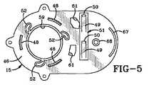
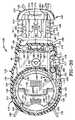
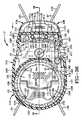
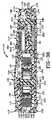
本発明の防犯装置は一般的に1で示され、図1から図3ではパッケージ3の周りにしっかり固定されて示される。防犯装置1は、一般的に5で示される主筐体(図4)と、内部スプール8上に収納される複数の、好ましくは2本のケーブル7とを含む。筐体5(図4B)は、好ましくは楕円形の側壁10によって形成される主筐体本体9を含み、内部スプール区画11およびロック区画13を有する。筐体5はさらに、複数の締結具17によって筐体本体9の頂部周縁上にしっかり固定される頂部カバープレート15(図4Aおよび図5)を含む。二重ケーブル7の一方端は内部スプール8に接続され、その他方端は装着クリップ19に接続される。DETAILED DESCRIPTION OF THE INVENTION The security device of the present invention is generally designated 1 and is shown securely around
ケーブル7は、楕円形の側壁10および湾曲壁57によって形成されるスプール区画11内に取込まれ、回転可能に含まれるスプール8上に収納され、頂部プレート15によってその中に保持される。巻取柱21(図9)は、スプール8中に形成された円形の孔22を通って延在し、好ましくは製造時に時計ばね23に予め張力をかけるのに用いられ、これによりスプール8に付勢を与えてこれを巻取り方向に回転させて、図9に示されかつ以下にさらに論じられるようにケーブルをスプール上の収納位置に引込む。スプール8は、間隔をあけられたフランジ25および26と介在壁31とを有し、これらの間にケーブル収納区域が形成される。一方向歯車の歯28の環状リング27は上側スプール26上に搭載され、筐体5内でのスプールの回転運動を制御するためのラチェット機構の一部を形成する。時計ばね23は張力付与部材29(図4A)の環状の内側部分の中に位置し、張力付与部材は、部材29を手動で回転させてパッケージ3の周りに配置された後にケーブルに張力を与えるためのクロスバー30を含む。時計ばね23の一方端93は巻取柱21に接続され、別の端がスプール8に接続される。1つの種類の接続は、部材29の円筒形の
側壁に形成されたスロット34を通って、スプール壁31中に形成されたスロット付き開口96の中へ延在するばね23に装着される突起33(図4B)によるものであり得る。張力付与部材29は、スプール8中に形成されたスロット32の中に延在する複数のスナップ式突起24によってスプール8に接続される。ケーブル7は、図2に示されるような筐体本体9の側壁10に形成された1対の孔36を通って出て行き、1対の位置決め玉状止め具38がそれに装着される。The
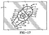
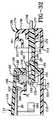
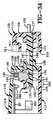
ラチェット機構は、一般的に35で示されるロッキングディスク(図4A)を含み、ロッキングディスクは、一方端にほぼ円形の構成を有し、当該一方端には中央部円形開口37が形成され、その中に複数の可撓性ロッキング爪39がアーチ状片持ち梁の態様で延在している。各々のロッキング爪は、一連の歯車の歯43に隣接して遠端に形成されるカム(camming)突起または柱41を有する。ロッキングディスク35は、以下にさらに論じられるように、ロッキングディスク反対端35の端部にほぼ矩形のセグメント45を有し、このセグメントは、1対のロッキングタイン(tine)49を受けてロッキングディスク35をロック位置にしっかり固定するための1対の先細凹部47を有するように形成される。タイン49は好ましくは金属ロッキングストリップ51から一体に形成され、それから外向きに付勢されると、図7、図9および図10に特に示されるように回転不可能なロック位置にロッキングディスク35をしっかり固定する。 The ratchet mechanism includes a locking disk, generally indicated at 35 (FIG. 4A), which has a generally circular configuration at one end with a central
矩形の1対の鍵受け凹部53はロッキングディスク35の矩形の端45に形成され、その目的を以下にさらに論じる。ロッキングディスク35は、ロッキングディスク(図9)の円形開口37の内周をスナップ式に係合する、カバープレート15上に形成される3つの湾曲突起48によって筐体カバープレート15の内側面46に装着される。スプール8の環状リング27は、ロッキングディスク35の円形開口37を通って上向きに延びて、ロッキング爪39の歯車の歯43が、ロッキング爪39の可撓性片持ち梁構成により、図7に示されるようにリング27の歯車の歯28と係合可能である。ロッキングディスク35はまた、ロッキング爪39の柱41がその中に向かって延びる、プレート15の表面46から突出しその上に形成される3つの湾曲したボス52に対して静止している。 A pair of rectangular
筐体頂部カバープレート15(図5)には、クロス部材30にアクセスできるようにし、張力付与部材29をその中で回転可能に受けるための円形開口59が形成される。カバープレート15も1対の鍵受けスロット61を含み、このスロットは、細長い構成を有し、ロッキングディスク35の鍵凹部53と整列している。鍵位置決め桟63がカバープレート15の外面上に形成されて、図11および図13に示されるように配置されると、磁気式鍵66(図19)の1対の鍵突起65を整列させ位置決めするのを助けるようにして、以下にさらに論じられるようにロッキングディスク35の凹部47内でのロッキング係合からロッキングタイン49をロック解除する。 A
本発明の独自のロッキング機構は、一般的に69で示される、回動するように搭載されたロックアーム(図4B)を含み、ロックアームは、湾曲端71と、対向端72と、介在ピボット73とを含む。端72はアーチ状のラチェット歯74の部分を有するように形成され、端71はそこから下向きに延在する1対のボス75を有するように形成される。ロックアーム69は、ピボット73を形成する開口の中に延びかつロック区画13の中に位置する柱77の上方端上に回動するように装着され、これにより、組立てられると、ラチェットの歯74が、図6に示されるようなロッキングディスク35の端45の底面上に形成されたラチェット歯78のアーチ状セグメントと嵌め合い係合する。ロックアーム69はピボット柱77上に形成された環状の肩70上で静止しかつこれによって支持され、アーチ状突起67と、プレート15の内側面上から延在する環状ボス68(図5および図9)とによって定位置に保持される。ピボット柱77の延在端はボス68内で受けられる。アーム69は壁57(図4B)に沿って形成された1対のリブ62によっても支持される
。ボス75は、装着クリップ19(図4B)の端に形成された1対の角度付きスロット80との解放可能な係合のため、側壁9の端に隣接して形成された桟76に形成された1対の湾曲開口79を通って延在する。装着クリップ19は、パッケージ3の周りにケーブルをしっかり固定するために係合ロック位置にある場合に、筐体壁10の端に形成されるアーチ状開口83に挿入されるように適合される。The unique locking mechanism of the present invention includes a pivotally mounted lock arm (FIG. 4B), generally indicated at 69, which includes a
図7に示されるように、ロック区画13に圧電アラーム85が搭載され、圧電アラーム85は、図8に示されるような筐体本体9の底部に形成された電池カバー88を通してアクセス可能な電池(図示せず)によって電力供給される、同様に区画13に搭載されるプリント回路基板87と動作するように係合される。EASタグ90は好ましくはロック区画13中に位置し、動作するように接続され、かつプリント回路基板87によって制御される。 As shown in FIG. 7, a
プリント回路基板87およびアラーム85によって提供されるアラームシステムは、この発明の概念の範囲内の、音響磁気(AM)、電磁(EM)および無線周波数(RF)などの異なるタイプのEASタグ90を実現し得る。さらに、電気検知ループがケーブル7によって提供されるため、ケーブルのうち1本が切断されたり防犯装置から切り離されたりすると、アラームシステムが音響圧電アラーム85を作動させる。また、EASタグ90は、もし泥棒が、保護された防犯ゲートの出口を通って、防犯装置が装着された保護物品を不正な態様で持ち出そうとしたならば、音響アラームまたは他の信号装置を防犯ゲートで作動させることが意図される。アラームシステムおよびその構成要素は防犯技術分野では周知であるので、さらに詳細には説明しない。 The alarm system provided by printed
組立てられた位置では、スプール8は筐体5内に巻取柱21上に回転可能に搭載され、ケーブル7は、ケーブルのうち2本が孔36(図2)を通って外向きに延びてクリップ19で終端した状態で、スプール上に収納される。スプール8は、筐体5の底部壁の中およびスプールの孔22を通って形成される相補形状の孔91を通って延在する巻取柱21上に回転可能に搭載される。1対のアーチ状突起92(図4B)が孔91を囲み、1対のスロット99を形成する。好ましくは張力付与装置1の製造後であって顧客への出荷前に、巻取柱21が時計ばね23に予め張力を付与する。時計ばね23の一方端93は、巻取柱21の中に形成されたスロット95に挿入され、時計ばねの別の端は、以上で論じられたようにスプール8の壁31に形成されたスロットを有する開口96の中へ張力付与部材29のスロット34を通って延在する突起33によってスプール8に固定される。巻取柱21は孔91およびスプール孔22に部分的に挿入され、次に予め定められた回転数だけ回転されて、時計ばね23を所望の張力まで張力付与する。次に柱21は孔91に完全に挿入され、その中で、柱21の底部に形成された1対の翼98がノッチ99に挿入されて柱21をその最終設置位置にロックし、ばね23に所望の張力が与えられて予め定められた回転力をスプール8に与える。一旦柱21を用いてばね23に張力を与えて筐体本体9に挿入すると、柱21は、複数の一方向スナップ式突起101によってその中に永久的に保持される。また、装置1が完全に組立てられると、ロッキング爪39の端の上に搭載されるカム突起41(図4A)は、カバープレート15の内側面上に形成された湾曲ボス52の内部に形成される湾曲凹部52Aの中に延在する。さらに、ロックアーム69の端にあるラチェット歯74は、図7Aに示されるように、ロッキングディスク35のラチェット歯78のアーチ状セグメントと係合する。ロッキング爪39の一方向歯車の歯43は、装置1が図7に示されるようなロック位置にある場合は、スプールリング27の歯車の歯28とロッキング係合し、以下にさらに記載されるような図15のロック解除位置にある場合はそれから係合解除される。 In the assembled position, the
本発明の改良されたケーブル巻付防犯装置の動作の態様は図7から図18に最もよく示される。図17に示されるようなロック解除された未装着位置では、スプール8はほどき
方向に空転する。店員は、矢印Aで示されるように、クリップ19を外向きに引張り、これによりスプール8の周りからケーブル7をほどく。ケーブルは、端スロット開口83の入口にクリップが存在する、図18に示されるような位置にクリップ19が達するまで、パッケージの角の付近に配置される。店員は、クリップ19を矢印Bに示されるように開口83に挿入し、これにより、クリップ19の角度付きスロット80への入口と整列したロックアーム69のボス75が、角度付きスロット80に沿って角度付けられた態様で移動する。この移動によりロックアーム69がピボット73の周りで回動し、これによりアーチ状ラチェット歯78(図7A)と係合しているラチェット歯74がロッキングディスク35を十分に回転させて、湾曲ボス52内での柱41の移動により歯車の歯43をスプールの歯28と係合するように移動させる。この結果、クリップ19、ボス75およびラチェット歯43は、図7に示されるようなロック位置をとるようになる。ロッキングタイン49は自動的に図16のロック解除位置から図10のロック位置に移動して、遠端50は凹部47の中および凹部47の端にある肩54と当接係合する。図7のこのロック位置では、クリップ19は、ロッキングアームボス75および角度付きスロット80の角度付き位置により、筐体5から係合解除されないようになっている。アーム75は、ラチェット歯74とロッキングディスク35のラチェット歯78との係合によりそれ以上移動することがないようにされている。なぜなら、ディスク35は、凹部47と係合するロッキングタイン49およびスプール26の一方向歯車の歯28とロッキング爪歯車の歯との係合によりそれ以上移動しないようにされているからである。ロッキングアーム69は、一方端でクリップ19によってしっかりと固定され、他方端でラチェット歯74によってしっかり固定されているので、移動しないようになっている。このように、ロッキングディスク39の爪の歯43がスプールの歯28としっかりと係合する。スプールの歯28と爪の歯43との係合により、ケーブルをほどく方向または放す方向へのスプールのいかなるさらなる回転も防止される。The mode of operation of the improved cable wrap security system of the present invention is best illustrated in FIGS. In the unlocked unmounted position as shown in FIG. 17, the
次に店員は、クロス部材30を掴んで回して張力付与部材29を手動で回転させることにより、張力付与方向にディスクスプール8を回転させる。通常は、部材30をわずかに回すだけで、防犯装置中へスプール8の周りにケーブルを引込むことによるパッケージの周りでのケーブルのさらなる締付には十分である。このしっかり固定された位置で、ケーブル7を通して設けられる内部アラームおよび検知ループは、ケーブルの不正な切断を防止し、EASタグ90の存在により、防犯ゲートを通って保護パッケージが不正に持ち出されないようにする。 Next, the store clerk rotates the
パッケージ3から防犯装置1を取外すためには、店員は、鍵位置決め桟63に対して鍵66を配置して、細長いスロット61を通るようにおよびロッキングディスク35の凹部53の中に突起65を配置して、ロッキングタイン49の各々と1対の内部磁石103とを整列させる(図11および図13を参照)。ロッキングタインは、磁石103に引寄せられ、図10のロック位置から図13のロック解除位置まで、凹部47内での係合から外れる。次にオペレータは、図14の矢印Dに示されるようにカバープレート15に沿ってごくわずかに鍵を動かすだけで、鍵の突起65がスロットを有する開口61に沿ってわずかに移動する。凹部53への鍵突起65の係合によりロッキングディスク35が回転し、爪の歯43をスプールのラチェット歯28から係合解除する。なぜなら、カム突起41は、湾曲ボス52を通って移動して、ロッキングディスク35が図12の位置から図15の位置まで反時計回りにわずかに回転するとスプールの歯28から爪の歯を完全に係合解除するからである。この動きにより、ラチェット歯78とラチェット歯74との係合によりロックアーム69が時計回り方向に回動し、これにより、ボス75がクリップスロット80内のロック位置から図15のロック解除位置まで移動する。この移動はまた、図13のロック解除位置から、ロッキングタインが凹部47の中へ付勢されて戻らないようにされている図16の位置へ、ロッキングストリップ51およびロッキングタイン49を移動させる。なぜなら、それらは、凹部との整列から外れてしまっているからである。図12お
よび図14に示されるようなロック解除位置に達すると、時計ばね23によって与えられている付勢がケーブル引込みまたはケーブル巻上げ方向にスプール8を回転させて、これによりケーブルが図14に示されるような矢印Dの方向に内向きに移動して、これにより図12の位置から図15の位置へ自動的にスプール8を回転させる。このように、ばね23によってケーブル7に与えられる引込み張力は自動的に、タイン49が凹部47内から持上げられた際に矢印Eの方向(図14)に筐体5内からクリップ19を引張り、ロッキングディスク35は、クリップを筐体内から係合解除する鍵突起65によってわずかに移動される。ばねによって与えられる引込み張力は継続してスプール8を引込み方向に回転させるため、以前に延ばされたケーブルは、図17に示されるものなどのように、スプール8上のその収納位置に自動的に引込まれるようになる。In order to remove the
クリップ19が図18の矢印Bに示されるようなアーチ状開口83を通って筐体本体9に再挿入されると、これらの工程と逆のことが起こる。これは、上述のように、クリップスロット80中のボス75の作用によってロッキングアーム69を回動させる。ここでも、この動きが、図7Aに示されるようなロッキングディスク上の歯車の歯78と歯車の歯74との係合によりロッキングディスク35をわずかに回転させ、これにより、爪の歯43が筐体頂部カバープレート15上に形成されたボス52のアーチ状凹部中のロッキング爪ボス41の移動によってスプールの歯28を係合する。このロッキングディスク35の移動は次に、ロッキングストリップ51および特にロッキングタイン49を図16の位置から図13の位置に移動させ、ここで、ロッキングタインに対する自然なばねの付勢により、ロッキングタイン49は自動的に凹部47の中に移動し、遠端50が凹部肩54と係合して、ロッキングタインが再び図10の位置から図16の位置まで鍵66の使用によって凹部から再び外れるまで、しっかり固定されロックされた位置にさまざまな部材を配置する。 When the
このように、本発明のロッキング装置は、装置内の引込み位置からケーブルを引張り出して時計ばね23が付与する付勢力に打ち勝つことにより、パッケージの周りでのしっかり固定されロックされた位置に容易に配置されるケーブル巻付防犯装置を提供する。ロッキング装置は、筐体5にクリップ19を挿入することによって自動的にロックされ、ラチェット機構を自動的に作動させて、繰出し方向またはほどく方向へのスプールの回転と結果的に装着されたケーブルの回転とを防止する。さらに、張力付与部材29の露出端をわずかに手動で回転させることにより、装置が磁気式鍵66などの特殊鍵によってロック解除されるまで、パッケージの周りのケーブルに対する所望の張力が達成されて、パッケージの周りからケーブルが外れないようになるまでさらなるケーブル巻上げ方向にスプール8に巻取ることによってケーブルをさらに引込む。また、ケーブルによって提供されるアラームシステムおよび検知ループにより、防犯装置内にしっかり固定され隠されたEASタグとともに、音響アラーム85の使用によってまたEASタグの使用によって防犯装置1に対するいたずらが防止されて、防犯対策を施された出口を通してパッケージ全体および装着された装置が持ち出されるのを防止する。 Thus, the locking device of the present invention can be easily fixed and locked around the package by pulling the cable from the retracted position in the device and overcoming the biasing force applied by the
図20はクリップ19とケーブル7との接続の代替的な実施例を示す。第1の実施例は特に図15に示されている。図15に示されるように、ケーブル7はクリップ19を通る連続ループを単に形成するに過ぎず、ケーブルとクリップとの間で強い機械的接続が与えられているものの、これは図20に示されかつ後述されるようなクリップ19へのケーブル7の代替的な接続によって与えられるような付加的なセキュリティを与えるものではない。図20に示されるように、ケーブル7は2本の別個のケーブルであり、その各々はわずかに拡大したコネクタ105の中で終端する。コネクタ105は、クリップ19の両側に形成されるスロット107内で受けられかつ保持されるケーブルの端上に圧力嵌めされ得る。ケーブルコネクタ105は各々、プリント回路基板87上に形成される適切な回路構成との接続によって電気的端子となるばねクリップ109と係合可能である。このよう
に、クリップ19が筐体9の端開口83を通ってまたはその中に挿入されると、ケーブル端子コネクタ105はばねクリップ109を機械的に係合して、プリント回路基板87を通る電気回路を完成させる。このように、クリップ19が筐体9から無理やり引抜かれると、プリント回路基板87を通して確立される電気的連続性を途絶させることになってアラーム85を鳴らすことになり、不正な出来事の発生が店員に知らされる。FIG. 20 shows an alternative embodiment of the connection between the
ある種類の圧力スイッチ、磁気スイッチなど(今回図示)を防犯装置1に組入れ、プリント回路基板のアラーム回路構成は、ロック機構の正当な開封および本体9からのクリップ19の取外しの際にはアラームを非活性化してアラームが鳴らないようにすることが容易に理解される。 A certain type of pressure switch, magnetic switch, etc. (shown here) is incorporated in the
所望により、この発明の概念に影響を及ぼすことなく、磁気吸引ロッキングタインの代わりに他の種類の防犯鍵を利用可能であることが容易に理解される。また、以上で示され説明されたような特定の時計ばね23および張力付与部材29以外にさまざまな種類の手動で作動される巻取装置およびばね機構も利用可能である。 It will be readily appreciated that other types of security keys can be used in place of the magnetic attraction locking tine, if desired, without affecting the inventive concept. In addition to the
本発明の変形された防犯装置が一般的に110で示され、特に図21から図40に示される。変形された防犯装置110は、一般的に113で示される主筐体を含み、主筐体は上部筐体部材114と、接着剤、音波溶接などによってともに接合されてケーブルスプール117が回転可能に搭載されるスプール区画116およびロック区画118を有する内部チャンバを形成可能な底部筐体部材115とを含む。上部筐体部材114は特に図22Aに示され、巻取機構121が回転可能に搭載される主円形開口119を有する細長い構成を有する。巻取機構121は、環状フランジ125の周に形成されるノッチ123の中に延在しかつスプール117上に形成される複数の突起122により、ケーブルスプール117に動作するように接続される。巻取機構121は、筐体開口119(図38)を取囲んで筐体113のスプール区画116内に巻取機構121を保持する、下向きに延在する環状突起127の下に位置する実質的に環状の外側フランジ125を含む。巻取機構121は、巻取機構の主ディスク状本体部分131上に1対のピボットピン130によって回動するように搭載される跳ね上げ式ハンドル129を含む。巻取機構121は、ケーブルスプール117とともに回転可能であるように、突起122によってケーブルスプール117にしっかり固定される。 A modified security device of the present invention is generally indicated at 110, and particularly shown in FIGS. The deformed
単一のループまたは1対のケーブルであり得るケーブル133はスプール117に接続され、他方のケーブル端は一般的に135で示される装着クリップに接続される。ケーブル133は、底部筐体部材115に形成される円形孔138に搭載される、円形プレート137(図22B、図24および図38)から上向きに延在する柱139上に、スプール区画116内に回転可能に搭載されるスプール117上に収納される。柱139はスロット141を有するように形成され、その中にコイルばね143の端142がしっかり固定され、これによりスプール117に付勢力が与えられて巻取り方向にスプールを回転させ、図38および図39に示されかつ以下にさらに論じられるようにスプール上にケーブルを収納位置に引込む。スプール117は間隔をあけられたフランジ145および146(図22Bおよび図25)と介在壁147とを有し、これによりその間にケーブル収納区域が形成される。スプール117に装着され筐体113を出て行くケーブル2本のみまたはケーブルループの使用は、筐体を出て行く4本のケーブルループまたは区間を有する米国特許第5,722,266号に示されるものなどのような先行技術のケーブル防犯装置に勝る改良である。これによりケーブルの絡まりが低減され、対象物の周りにケーブルを配置した後に手動でスプールを回転させた場合に4つのケーブルループに対して可能であるよりも大きな巻上げ張力が2つのケーブルループに対して加えられるようになる。 A
ケーブル133をスプールにしっかり固定するための複数のノッチ144を壁147に
形成してもよい。複数の歯車の歯149は、好ましくはスプールフランジ145および146の両方の外周上に形成され、スプール区画116内でのスプール117の回転運動を制御するためのラチェット機構の一部を形成する。コイルばね143は、図38に示されるように、スプール柱139がその中を通って延在する底部壁153に形成される中央孔152を有する円筒形ばね保持具151(図29)内に着座する。保持具151は、スプールフランジ145によって筐体底部部材115に対して挟持される。ばね143の第2の端155は、ばね保持具側壁157(図22B)の中に形成されてばね143をばね保持具151にしっかりと固定するスロット156に挿入される。以上で論じたような巻取機構121はスプール117に固定され、跳ね上げ式ハンドル129を用いて、以下にさらに論じられるように手動で回転されて、図33の矢印Aで示されるように時計回り方向にスプール117を回転させて、ばね143の付勢力によってケーブルを筐体113内に引込んだ後に製品の周りでケーブル133を締める。ケーブル133は、上部筐体部材114の細長い側壁160の一方端に形成された1対の孔159を通って筐体113を出て行く。A plurality of
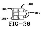
スプールの歯149と係合してほどく方向にスプールが動かないようにするラチェット機構は、ばねによって付勢されるスプールロッキングレバー162(図22Bおよび図28)を含み、これは、U字状ばね163によって付勢されて、スプールフランジ145および146上に形成されたスプールの歯車の歯と係合する。ロッキングレバー162は、図39に示されるようにピボットピン165によってスプール区画116内に回動するように搭載され、スプールの歯と係合する向きに付勢される。図28に示されるように、間隔をあけられた1対の突起166がロッキングレバー162の一方端上に形成され、この突起は、図30に示されるようなフランジ145および146上の間隔をあけられた1対の歯車の歯と係合する。1対の歯車の歯および1対の突起166を用いることにより、泥棒による不正行為に対する耐性が増大するとともに、防犯装置110に対する防犯突起(security projections)が増大する。なぜなら、そうすることにより、装着されたケーブルに対するより大きな張力に耐えることができるからである。 The ratchet mechanism that prevents the spool from moving in the unwinding direction in engagement with the
この発明の特徴のうち1つに従うと、解除ボタン169(図22Bおよび図30)は、スプール区画116にピボットピン165によって回動するように搭載される。解除ボタン169はピボットから反対側の端に外向きに突出する爪171を含み、その機能を以下にさらに論じる。この発明の別の特徴に従うと、装着クリップ135(図22A)は、一般的に173で示されるロッキングクリップと、クリップハウジング174とを含む。ケーブル133は、1対の金属フェルール(ferrule)175によってロッキングクリップ173中にしっかり固定された2つのケーブル区間として示される。フェルール175はケーブル133の端に装着され、クリップ173の中に形成されてケーブルをロッキングクリップ173の一方端にしっかり固定する区画167の中に着座する。ケーブル133は、クリップハウジング174の端壁178に形成された細長いスロット177(図27)を通して外向きに延在する。ロッキングクリップ173は一般的に矩形の平面構成を有し、スロット170によって1対の脚部168に分割される。各々の脚部は間隔をあけられた第1の対の凹部179(図22Aおよび図31)を有するように形成され、その各々は直角の肩184と反対側の上向きに延在する先細の後部壁180の中で終端し、また各々の脚部は凹部179から後方に間隔をあけられた第2の対の凹部181を有する。ロッキングクリップ脚部168の前方周縁は、第1の対の凹部179に隣接する先細面183を有する。これらの凹部および角度付き面の機能を、ロック区画118内の装着クリップ135の配置およびロッキングに関して以下にさらに論じる。 According to one of the features of the present invention, the release button 169 (FIGS. 22B and 30) is mounted on the
一般的に185で示されるロッキング機構は、筐体113の装着クリップ入口端186に搭載される。入口端186は、以下にさらに論じるように、摺動可能にロッキングクリップ173を受けるための外向きに延在する矩形のフレーム188(図31)によって形
成されたスロットを有する開口187を備えるように形成される。ロッキング機構185は、金属などの磁気的に吸引可能な材料から好ましくは形成される、間隔をあけられた1対のロッキングプランジャ190を有するロッキングシャトル189を含む。ロッキングシャトルは、ロッキングクリップ173の凹部179および181の中に係合可能で、装着クリップ135を筐体113にドッキングする端ロッキング突起191を有する。シャトル189は窪んだ凹部188を有し、これは、ロック位置にある際は電池199からの隙間を設ける。上部筐体部材114(図23および図35)の内側面上に一体に形成されかつロッキングシャトル189(図22Aおよび図35)の中に形成される整列孔197の中に延在する1対の柱195の周りに1対のコイルばね193が搭載される。ばね193は、ロッキングシャトル189および特にロッキングプランジャの端191を、ロッキングクリップ173の凹部179および181とロッキング係合するように付勢する。A locking mechanism, generally designated 185, is mounted on the mounting
変形された防犯装置110は、ロック区画118内に位置し、電池199(図38)によって電力供給されるプリント回路基板87と動作するように係合する圧電アラーム85を含む。光導体200(図38)は、回路基板87上に搭載されるLED201に隣接して、上部筐体部材114中に形成される孔202の中に搭載され得る。LEDは、プリント回路基板87上に形成されたアラーム回路構成が、装着クリップ135および特にロッキングクリップ173が図21、図35、図36、図37および図38に示されるような最終的なそのロッキング位置にあるときに活性化されると点灯する。この最終ロック位置において、ケーブル133の端上に搭載されるフェルール175は、プリント回路基板87から下向きに延在する電気コンタクト203と係合し、これに電気的に接続して、コンタクト203とフェルール175との間の電気的接続によってケーブル133を通してプリント回路基板87のアラーム回路を完成させる。これにより、ケーブル133を通って延びる検知ループが提供される。EASタグは、所望によりロック区画118内または装置110内の他の場所に搭載されて、装置により一層のセキュリティを付加することができる。 The modified
ケーブルクロスオーバーパッド205(図21)をケーブル133上に搭載してもよく、これは一般的に防犯装置110の側とは反対側のパッケージ上に位置する。パッド205は保護されるパッケージまたは他の品目の周りでケーブルを維持するのを助け、ケーブルがパッケージの周縁から滑り落ちにくくする。パッド205はまた、206で示される、筐体113に含まれるアラーム回路構成のうちの一部を含むことも可能である。クロスオーバーパッド205の中にアラーム回路構成の電子部品の一部を配置することにより、防犯装置110のサイズおよび複雑さを減じることができる。所望によりクロスオーバーパッド205の中またはその上にEASタグも容易に配置することができる。 A cable crossover pad 205 (FIG. 21) may be mounted on the
変形された防犯装置110の動作の態様が図30から図40に最もよく示される。図30に示されるようなロック解除位置では、店員は、図33に示されるものなどのボタン169を押下して、ロッキングレバー163を反時計回り方向に回動させる。なぜなら、ボタン169の表面216はロックレバー162(図22B)の表面217と当接するように係合しているからである。ロッキングレバー162のこの回動運動は、歯車の歯149から突起166を係合解放し、ほどく方向にスプール117を空転状態にする。店員は装着クリップ135上を外向きに引張り、これによりスプール117に対するばね143のいかなる付勢にも打ち勝って、スプール117の付近から十分な量のケーブル133をほどいて、装着クリップ135が入口スロット開口187にある図30に示すような位置にクリップ135が達するまで、ケーブルをパッケージの角の周りに配置する。スプール117からこのケーブル133をほどくと、ケーブル133をスプール上に巻取ろうとする張力がスプールばね143にさらに付与される。しかしながら、これは、店員がボタン169に対する圧力を解放することによって防止される。なぜなら、Uばね163は、ロッキングレバー162およびその突起166を、歯車の歯149とのロッキング係合に戻す
ように付勢するからである。次に店員は、図30、図31の非ラッチおよび非ロック位置から図32および図33の部分的ロック位置へ、クリップ135をスロット開口187に挿入する。ロッキングクリップ173がスロット開口187(図32)を通して挿入されると、ロッキングクリップ173の先細のまたは傾斜した端183は、図31のそれらの下向きに付勢された位置から矢印Bで示されるような図32の持上げられる位置にロッキングプランジャ190を移動させる。ロッキングクリップ173が図32の位置から図33および図34の第1のロック位置まで筐体113の開口187にさらに挿入されると、ロッキングプランジャ190は、第1の対の凹部179の中へばね193によって下向きに付勢される。図37のこの第1のロック位置にあると、ロッキングクリップ173は筐体113から外れないようにされる。The mode of operation of the modified
スプール117がばね143によって巻取り方向に付勢されていても、スプールの歯149を係合するレバー突起166をロックすることにより、スプール117がケーブルを引込まないようにされる。次に店員はパッケージの周りにケーブルを位置決めして、次に図33の矢印Fで示されるようにボタン169を押下する。ばね143は巻取り方向にスプール117を回転させ、これによりケーブルの弛みがスプール117の付勢された回転によって自動的に巻上げられることにより、パッケージの周りのケーブルに自動的に張力が付与される。次に店員は、矢印Dの方向に図33の第1のロック位置から図36の完全ロック位置へ装着クリップ135を移動させる。この移動の間に、ロッキングクリップ173は、図34の第1のロック位置から図37の完全ロック位置へ移動し、ロッキング突起190はそれらが上向きに先細になった面180に沿って移動するにつれてまず上向きに持ち上がり、その後自動的にロッキング凹部181の中に落ちて、縦の壁または肩184によって後方へ移動しないようにされる。この完全ロック位置に達すると、フェルール175はプリント回路基板87の電気コンタクト203と係合し、ケーブル133の導体およびアラーム回路を通る電気経路を設け、ケーブルを通る検知ループを設けるので、ケーブル133が潜在的な泥棒によって切断された場合は、圧電アラーム85が鳴る。図36および図37のこの完全ロック位置に移動する前に、ボタン169の押下が取除かれると、その結果、Uばね163はロッキングレバー162を内向きに付勢し、これによりロッキング突起166は図30に示されるような隣接する歯車の歯149の中に入る。このロック位置にある場合、ボタン169の爪171は、ロッキングクリップ173(図36)の側面端縁207に隣接して位置する。これは、ボタン169が内向きに押下されることを防止し、ロッキング突起166が歯車の歯49内から外れるのを防止する。このように、ロッキングクリップ173が図35、図36および図37の完全ロック位置に達すると、ケーブルは、コイルばね143によってケーブル133に加えられる力によりパッケージ付近で張力を付与される。しかしながら、店員は、巻取機構121の跳ね上げ式ハンドル129を単に持上げて、スプール117に装着された巻取機構を図39の矢印Aで示されるような時計回り方向に手動で回転させて、所望の張力までパッケージの周りでケーブルをさらに締める。ケーブルは締付または巻取り方向に移動する。なぜなら、ロッキングレバー162は、ボタン面216とロッキングレバー面217との当接によりスプールの歯149と係合していると、図39に示されるように反時計回り方向に回動することはできるが、時計回り方向に回動することができないからである。ボタン169は、ロッキングクリップ173の側面端縁207と爪171との係合により、内側へ動かないようにされている。フェルール175とプリント回路基板コンタクト203との間の接触はアラーム回路構成を活性化させ、LED201を点灯させる。LEDは、光導体200を通して店員および潜在的な泥棒に認識される。 Even if the
ロックされた機構をロック解除するため、磁気式鍵66(図19)は、クリップハウジング174中に形成された整列孔211の中に突起65を挿入しかつ位置付けることによって、クリップハウジング174の頂面上に適切に配置される。この整列により、図40に示されるように、磁石103がロッキングプランジャ190と適切に整列されることが
確実になる。磁石103は、図35のそれらのロック位置から矢印Eで示されるような図40のロック解除位置へロッキングプランジャ190を移動させる。図40のロック解除位置に達すると、クリップ173は、スロット開口187を通してロッキングクリップを摺動させて外に出すことにより、筐体113から容易に取外される。To unlock the locked mechanism, the magnetic key 66 (FIG. 19) is inserted into the
この発明の別の特徴に従うと、磁石103に向けた吸引によりプランジャ190およびシャトル189が上向きに移動すると、シャトル189は、プリント回路基板87(図32および図37)上に搭載されたスイッチ210を係合しこれを押下する。これによりアラーム回路構成が非活性化されて、筐体113からクリップ135が取外された際にアラームが鳴らなくなる。 According to another feature of the invention, when
装着クリップ135が筐体113から取外されて図30の位置に戻された後、爪171はロッキングクリップ173の側面端縁207から係合解除され、この結果、ボタン169を押下することができるようになり、スプールの歯149からロッキング突起166を係合解除し、これによりばね143によって加えられている付勢力により筐体の中へおよびスプール117の周りにケーブルが自動的に引込まれる。このように、店員は、鍵66を筐体の中に配置した後、筐体113の中から装着クリップ135を単に取外して解除ボタン169を押下することにより、クリップ135が入口端186の位置から筐体113の反対側端の非常に隣接した位置に達するまで、またはクロスオーバーパッド205が防犯装置110と共に用いられている場合はパッド205が筐体113の端と係合するまで、ケーブルが筐体の中に戻ってスプールの周りに巻取られるのを制御する。この筐体の中へのケーブルの自動引込みにより、これまでは隣接する製品または他の防犯装置およびケーブルと絡まっていた余ったケーブルが筐体113からぶらぶらしたままにならなくなる。 After the mounting
上述の防犯装置1と同様に、アラームシステムは所望のセキュリティを与え、内部アラームを鳴らさずにケーブル133が切断されるのを防止し、さらに跳ね上げ式ハンドル129を容易に手動で回転させることにより所望の張力まで製品の周りでケーブルを締めることができるようになる。クロスオーバーパッド205を変形された防犯装置110と共に用いても用いなくてもよく、これはアラーム回路構成の一部を含んだり、または以上で論じられたようなEASタグをその中に内蔵してもしていなくてもよいことが容易に理解される。 Similar to the
図37および図39に示されるような完全ロック位置にある場合、クリップハウジング174の内側端縁214との間に僅かなギャップ213が形成され得る。これにより、装着クリップ135は、店員が防犯装置110をロック解除して筐体から装着クリップ135を取外し始めると、図37に示されるように矢印Fの方向に僅かに内向きに手動で移動され得る。この僅かな内向きの移動により、これまでは筐体113内からの係合から装着クリップ135を引抜こうとするコイルばねの張力によって共に固く挟持されていた、凹部肩184を備えるロッキングプランジャ端191の端縁との間に生じる摩擦力をなくすことにより、ロッキングプランジャ190の上向きの移動が容易になる。このように、図40に示されるような位置に磁気式鍵66を配置することにより、店員は、装着クリップ135を僅かに内向きに押して、ロッキングプランジャが引込まれて筐体内からの装着クリップのロック解除および取外しが容易になるまで、ロッキングプランジャとロッキングクリップとの間の圧力を低減させる。さらに、スプール117の周りでのケーブル2本のみまたは1つの連続ケーブルループの使用により、スプール上にケーブルがよりきつく巻取られるようになり、かつロッキングレバーに対する力がより小さくてすみ、その結果、先行技術のケーブル巻付防犯装置におけるような4本の別個のケーブルが用いられる場合に発生するよりもケーブルの絡まりがかなり少なくなる。 A
さらに、図21に示されるような筐体113の細長くやや楕円形の形状は、防犯装置が円形である場合よりも、店員による把持がより容易な装置を提供する。なぜなら、これは、店員の手の中で常に把持された位置に留まるので、ボタン169の押下の際のスプールからのケーブルのほどきおよび巻取りがさらに容易になるからである。 Furthermore, the elongated and slightly elliptical shape of the
防犯装置110の別の利点は、圧電アラーム85が、図38に示されるような底部筐体部材115および複数のスピーカ孔215(図22B)に非常に隣接して位置して、孔が防犯装置の頂部に露出している場合にスピーカ孔を通してスピーカおよび電子部品にアクセスしようとし得る潜在的泥棒からの保護を与えることである。この結果、防犯装置110が対象物にしっかり固定されている場合にスピーカ孔およびアラームが下を向くことになり、スピーカ孔が露出している場合に起こり得る、スピーカ孔を通した尖った物体の挿入による泥棒によるアラーム不能化ができなくなる。筐体内にアラームが内蔵されているかもしれないことを泥棒に示す、擬似スピーカ孔220をディスク131に形成してもよい。さらに、小さな孤立した足部または突起222が好ましくは底部筐体部材115の底面から延在して、スピーカ孔としっかり固定された対象物との間のギャップまたは間隔を設けることによって、作動した場合にアラーム85からの音の伝達がよりよくなる。 Another advantage of the
本発明に従うと、2つの別個のクリップとして装着クリップ135を形成することも可能である。その場合、その各々は、1対のケーブルのうち一方に装着され、筐体の端開口を通して個別に挿入され、上述のものと同様のロッキング機構によってロックされる。これにより、ケーブルのうち少なくとも1つがそれによって保護される製品の小さな開口を通して挿入可能になり、製品が箱または同様の直方体構成を有する必要なく、その製品に対する保護を与える。同様に、装着クリップ135を、筐体113にラッチされる前に製品の開口を通して挿入することができ、これにより製品を支持構造などにしっかり固定し得る、アラームを有する防犯装置を提供することができることが理解される。 According to the present invention, it is also possible to form the mounting
防犯装置110の別の利点は、ケーブル133に対して大きな力が加えられると、ケーブルがフェルール125(図30)から離れるように引張られ得、さもなければフェルールとコンタクト203(図37)との電気コンタクトが破壊され、アラーム85を作動させることである。 Another advantage of the
ここでも、ロック解除位置にある場合に筐体から取外される装着クリップへのケーブルループまたはケーブル区間2つのみの装着は、必要とされるまでの筐体内へのケーブル引込みを可能にし、先行技術のケーブル巻付防犯装置で発生するような絡まりやすい露出ケーブルをなくす。同様に、引込みばね機構は、手動でケーブルを締める前であって対象物の周りにケーブルを配置した後およびケーブルが保護対象物から取外された後に、容易にケーブルの弛みを巻上げることができるようにする。 Again, the attachment of only two cable loops or cable sections to the mounting clip that is removed from the housing when in the unlocked position allows the cable to be pulled into the housing until it is needed. Eliminate exposed cables that tend to get tangled, such as those found in technical cable wrap security equipment. Similarly, the retraction spring mechanism can easily wind up the slack in the cable before manually tightening the cable, after placing the cable around the object and after the cable is removed from the protected object. It can be so.
本明細書中で使用されるような「ロック」または「ロックされた」という用語は、要素を元通りにするのに鍵を必要としない2つの要素間の接続を表わす「ラッチされた」という用語からの区別のため、ロック状態からロック解除状態へ変化させるには何らかの種類の鍵が必要であることを意味する。 The term “locked” or “locked” as used herein refers to “latched” which represents a connection between two elements that does not require a key to restore the element. For distinction from the terminology, it means that some kind of key is required to change from the locked state to the unlocked state.
以上の説明では、簡潔さ、明確さ、および理解のためにある用語が使用された。先行技術の要件を超えて不要な限定がそれらから暗示されるべきではない。なぜなら、そのような用語は記述の目的のために用いられるものであり、広く解釈されることが意図されるからである。 In the foregoing description, certain terminology has been used for the sake of brevity, clarity and understanding. No unnecessary limitations should be implied from them beyond the requirements of the prior art. This is because such terms are used for descriptive purposes and are intended to be interpreted broadly.
さらに、この発明の説明および図示は例示的なものであり、この発明は示されたまたは説明された正確な詳細に限定されるものではない。 Furthermore, the description and illustration of the invention is exemplary and the invention is not limited to the exact details shown or described.
Claims (26)
Translated fromJapanese筐体と、
前記対象物の周りに配置するためのケーブルと、
前記筐体の中に回転可能に搭載され、前記ケーブルの第1の端に動作するように装着されるスプールと、
前記ケーブルの第2の端に装着され、前記筐体に挿入されて前記対象物の周りに前記ケーブルをしっかり固定するためのクリップとを備え、このクリップは前記筐体内へ第1のロック位置まで挿入可能でありかつ前記筐体内で前記第1のロック位置から第2のロック位置へ移動可能であり、
前記筐体に前記クリップをロックするためのロック機構をさらに備え、前記スプールは前記クリップが前記第1のロック位置にあるときに空転しかつ前記クリップが前記第2のロック位置にあるときに空転できず、
前記ケーブルが前記対象物の周りで締め付けられた状態で維持されるように、前記スプールと動作するように係合可能なラチェット機構と、
前記筐体から前記クリップをロック解除するための鍵と、
前記ケーブルの巻上げ方向に前記スプールを自動的に回転させて前記ケーブルを前記スプールに巻取るための引込み機構とをさらに備える、防犯装置。A security device for placement around an object,
A housing,
A cable for placement around the object;
A spool rotatably mounted in the housing and mounted to operate on the first end of the cable;
A clip attached to a second end of the cable and inserted into the housing for securely securing the cable around the object, the clipinto the housing to a first locked position Is insertable and movable from the first locked position to the second locked position within the housing ;
A locking mechanism for locking the clip to the housing; thespool idles when the clip is in the first locking position and idles when the clip is in the second locking position; I ca n’t
A ratchet mechanism operably engageable with the spool such that the cable is maintained clamped around the object;
A key for unlocking the clip from the housing;
A security device,further comprising: a retracting mechanism for automatically rotating the spool in the winding direction of the cable and winding the cable onto the spool.
筐体と、
前記筐体から延在して前記対象物の周りに配置されるためのケーブル区間を2つのみ有するケーブルと、
スプールが前記ケーブル区間の第1の端に接続されて、前記ケーブル区間を前記対象物の周りで締めるためのラチェット機構と、
前記ケーブル区間の第2の端に接続され、前記筐体と取外し可能に係合されるロッキングクリップとを備え、このロッキングクリップは前記筐体内へ第1のロック位置まで挿入可能であってこれによって前記スプールが空転し、かつ前記ロッキングクリップは前記第1のロック位置から第2のロック位置へ移動可能であってこれによって前記スプールが空転できず、
前記ケーブルを前記対象物の周りにしっかり固定するように、前記筐体とのロック位置に前記クリップをロックするためのロック機構をさらに備える、防犯装置。A security device adapted to be placed around an object,
A housing,
A cable having only two cable sections extending from the housing and arranged around the object;
A ratchet mechanism, wherein a spool is connected to the first end of the cable section to tighten the cable section around the object;
A locking clip connected to a second end of the cable section and removably engaged with thehousing, the locking clip being insertable into the housing to a first locking position, thereby The spool is idle, and the locking clip is movable from the first locked position to the second locked position, whereby the spool cannot idle ,
A security device, further comprising a lock mechanism for locking the clip in a locked position with the housing so as to firmly fix the cable around the object.
内部スプールを有する筐体と、
前記スプールに動作するように接続され、前記筐体から延在して前記対象物の周りに配置されるためのケーブルと、
前記ケーブルに装着され、前記筐体と取外し可能に係合されるクリップと、
前記クリップを前記筐体にロックするための磁気的に作動されるロック機構とをそなえ、このロック機構は前記クリップを前記筐体へ第1のロック位置でロックしてそこでは前記スプールが空転しかつ前記クリップを前記筐体へ第2のロック位置でロックしてそこでは前記スプールが空転できず、
前記クリップを前記筐体からロック解除するように前記ロック機構を作動させるように前記クリップ上に位置決め可能な1対の磁石を有する鍵をさらに備える、防犯装置。A security device adapted to be placed around an object,
A housing having an internal spool;
A cable operatively connected to the spool, extending from the housing and arranged around the object;
A clip attached to thecable and removably engaged with the housing;
A magnetically actuated locking mechanism for locking theclip to the housing, the locking mechanism locking the clip to the housing in a first locked position where the spool is idled. And the clip is locked to the housing at a second locking position, where the spool cannot idle ,
A security devicefurther comprising a key having a pair of magnets positionable on the clip to actuate the locking mechanism to unlock the clip from the housing.
Applications Claiming Priority (5)
| Application Number | Priority Date | Filing Date | Title |
|---|---|---|---|
| US92054607P | 2007-03-28 | 2007-03-28 | |
| US60/920,546 | 2007-03-28 | ||
| US12/027,296 | 2008-02-07 | ||
| US12/027,296US8122744B2 (en) | 2007-03-28 | 2008-02-07 | Cable wrap security device |
| PCT/US2008/003512WO2008118301A1 (en) | 2007-03-28 | 2008-03-18 | Cable wrap security device |
Publications (2)
| Publication Number | Publication Date |
|---|---|
| JP2010522930A JP2010522930A (en) | 2010-07-08 |
| JP5378347B2true JP5378347B2 (en) | 2013-12-25 |
Family
ID=39788810
Family Applications (1)
| Application Number | Title | Priority Date | Filing Date |
|---|---|---|---|
| JP2010500922AActiveJP5378347B2 (en) | 2007-03-28 | 2008-03-18 | Cable winding crime prevention device |
Country Status (7)
| Country | Link |
|---|---|
| US (4) | US8122744B2 (en) |
| JP (1) | JP5378347B2 (en) |
| CN (1) | CN101663450B (en) |
| AU (1) | AU2008230097B2 (en) |
| CA (1) | CA2719521C (en) |
| MX (1) | MX2009010341A (en) |
| WO (1) | WO2008118301A1 (en) |
Families Citing this family (79)
| Publication number | Priority date | Publication date | Assignee | Title |
|---|---|---|---|---|
| US7428833B2 (en)* | 2004-12-22 | 2008-09-30 | Peak Recreational Products, Llc | Vehicle mountable personal property lock assembly |
| US7168275B2 (en)* | 2004-12-28 | 2007-01-30 | Alpha Security Products, Inc. | Cable wrap security device |
| US7659817B2 (en)* | 2005-11-29 | 2010-02-09 | Checkpoint Systems, Inc. | Security device with perimeter alarm |
| US9404291B1 (en)* | 2015-03-04 | 2016-08-02 | Checkpoint Systems, Inc. | Device and method for an alarming strap tag |
| US9487970B2 (en)* | 2007-03-28 | 2016-11-08 | Checkpoint Systems, Inc. | Cable wrap security device |
| US8122744B2 (en)* | 2007-03-28 | 2012-02-28 | Checkpoint Systems, Inc. | Cable wrap security device |
| US7715679B2 (en) | 2007-05-07 | 2010-05-11 | Adc Telecommunications, Inc. | Fiber optic enclosure with external cable spool |
| US7756379B2 (en) | 2007-08-06 | 2010-07-13 | Adc Telecommunications, Inc. | Fiber optic enclosure with internal cable spool |
| US8087269B2 (en)* | 2008-02-07 | 2012-01-03 | Checkpoint Systems, Inc. | Cable wrap security device |
| US8228192B2 (en)* | 2008-05-30 | 2012-07-24 | Checkpoint Systems, Inc. | Cable lock closure with defeat prevention |
| SE533099C2 (en)* | 2008-07-22 | 2010-06-29 | Mw Security Ab | Security device with gripping means for enclosing an object to be protected |
| US8453937B2 (en)* | 2008-08-13 | 2013-06-04 | B&G International Inc. | Security hang tag with swivel head |
| USD599693S1 (en)* | 2008-08-27 | 2009-09-08 | Sayegh Adel O | Theft deterrent tag having crossing lanyard for use with articles |
| US8542119B2 (en)* | 2009-01-13 | 2013-09-24 | Invue Security Products Inc. | Combination non-programmable and programmable key for security device |
| CN102439642A (en)* | 2009-03-12 | 2012-05-02 | 关卡系统公司 | Disposable cable lock and detachable alarm module |
| US8833115B2 (en)* | 2009-06-22 | 2014-09-16 | Kabushiki Kaisha San-Ei | Antitheft device for a product display case |
| EP2496781A2 (en)* | 2009-11-02 | 2012-09-12 | Checkpoint Systems, Inc. | Adjustable dual loop cable security device |
| US10232150B2 (en) | 2010-03-11 | 2019-03-19 | Merit Medical Systems, Inc. | Body cavity drainage devices and related methods |
| US8837940B2 (en) | 2010-04-14 | 2014-09-16 | Adc Telecommunications, Inc. | Methods and systems for distributing fiber optic telecommunication services to local areas and for supporting distributed antenna systems |
| US8640509B2 (en) | 2010-04-30 | 2014-02-04 | Checkpoint Systems, Inc. | Security assembly for attachment to an object |
| WO2011143529A1 (en)* | 2010-05-13 | 2011-11-17 | Checkpoint Systems, Inc. | Cable ratchet security device |
| CH703299A1 (en)* | 2010-06-07 | 2011-12-15 | Pataco Ag Ind Und Unterhaltungselektronik | Safety device for objects. |
| AU2010355632B2 (en) | 2010-06-18 | 2014-09-18 | Adc Communications (Shanghai) Co., Ltd. | Fiber optic distribution terminal and method of deploying fiber distribution cable |
| CN110174737A (en) | 2010-06-23 | 2019-08-27 | Adc电信公司 | Telecommunication assembly |
| US8730046B2 (en)* | 2010-10-01 | 2014-05-20 | B&G Plastics, Inc. | EAS integrated faucet tag assembly |
| WO2012047884A1 (en)* | 2010-10-04 | 2012-04-12 | Checkpoint Systems, Inc. | Adjustable cable securty device |
| US8810437B2 (en) | 2011-02-02 | 2014-08-19 | Mapquest, Inc. | Systems and methods for generating electronic map displays with points-of-interest information based on reference locations |
| US9105168B2 (en)* | 2011-03-09 | 2015-08-11 | Checkpoint Systems, Inc. | Method and apparatus for securing related products |
| US9328536B2 (en)* | 2011-06-20 | 2016-05-03 | Checkpoint Systems, Inc. | Multipurpose security device and associated methods |
| CA2877896C (en) | 2011-06-24 | 2020-07-21 | Adc Telecommunications, Inc. | Fiber termination enclosure with modular plate assemblies |
| CN102956085A (en)* | 2011-08-17 | 2013-03-06 | 上海维恩佳得数码科技有限公司 | Anti-theft security device for binding strap |
| US8813528B2 (en)* | 2011-09-20 | 2014-08-26 | Jordan A. Olear | Theft prevention apparatus for a personal electronic device |
| WO2013049481A1 (en)* | 2011-09-29 | 2013-04-04 | Invue Security Products Inc. | Cabinet lock for use with programmable electronic key |
| US20130098122A1 (en)* | 2011-10-19 | 2013-04-25 | Checkpoint Systems, Inc. | Cable lock with integral connected metal sheath |
| USD693257S1 (en) | 2011-12-08 | 2013-11-12 | Xiao Hui Yang | Electronic security apparatus with tether |
| US9188760B2 (en) | 2011-12-22 | 2015-11-17 | Adc Telecommunications, Inc. | Mini rapid delivery spool |
| US8938997B2 (en) | 2012-01-05 | 2015-01-27 | Checkpoint Systems, Inc. | Security surround device with cord lock |
| TWM436305U (en)* | 2012-03-27 | 2012-08-21 | Hon Hai Prec Ind Co Ltd | Cable holder |
| WO2013173278A1 (en)* | 2012-05-15 | 2013-11-21 | Checkpoint Systems, Inc. | Cable wrap security device |
| US9070265B2 (en) | 2012-08-21 | 2015-06-30 | Tyco Fire & Security Gmbh | Security tag for application to footwear |
| US20140077954A1 (en) | 2012-09-20 | 2014-03-20 | Tyco Fire & Security Gmbh | Security tag for application to footwear |
| ES1141660Y (en) | 2012-12-19 | 2015-10-14 | Tyco Electronics Raychem Bvba | Distribution device with incrementally added dividers |
| DE102013003312A1 (en) | 2013-02-28 | 2014-08-28 | Deutsche Telekom Ag | alarm device |
| WO2015054192A1 (en) | 2013-10-08 | 2015-04-16 | Invue Security Products, Inc. | Quick release sensor for merchandise display |
| EP3071769B1 (en)* | 2013-11-18 | 2019-04-10 | InVue Security Products, Inc. | Wrap for an item of merchandise |
| USD729740S1 (en)* | 2013-11-26 | 2015-05-19 | Kui-Hsien Huang | Positioning device for wire retractors |
| US9792792B2 (en)* | 2014-02-14 | 2017-10-17 | B&G Plastics, Inc. | Security tag for wire handle |
| US10029036B2 (en) | 2014-06-27 | 2018-07-24 | Merit Medical Systems, Inc. | Placement tools for body cavity drainage devices and related methods |
| US9649415B2 (en) | 2014-06-27 | 2017-05-16 | Harrison M. Lazarus | Surgical kits for body cavity drainage and related methods |
| US9821097B2 (en) | 2014-06-27 | 2017-11-21 | Merit Medical Systems, Inc. | Body cavity drainage devices including drainage tubes having inline portions and related methods |
| US9604033B2 (en)* | 2014-06-27 | 2017-03-28 | Harrison M. Lazarus | Body cavity drainage devices with locking devices and related methods |
| CN105375197B (en)* | 2014-08-22 | 2017-12-26 | 鸿富锦精密工业(深圳)有限公司 | Electronic product |
| TWI513381B (en) | 2014-08-22 | 2015-12-11 | Hon Hai Prec Ind Co Ltd | Electronic device |
| EP3183708A1 (en)* | 2015-11-09 | 2017-06-28 | Ascent Solutions Pte Ltd. | Location tracking system |
| JP7074666B2 (en) | 2015-11-25 | 2022-05-24 | メリット・メディカル・システムズ・インコーポレイテッド | Maneuverable sheath catheter and how to use |
| US9805563B2 (en) | 2015-12-03 | 2017-10-31 | Checkpoint Systems, Inc. | Security device |
| US9816297B2 (en)* | 2015-12-14 | 2017-11-14 | Checkpoint Systems, Inc. | Security device with multiple control states |
| WO2018102403A1 (en)* | 2016-11-30 | 2018-06-07 | Invue Security Products | Recoiling cable wrap |
| US10352068B2 (en) | 2017-02-07 | 2019-07-16 | Master Lock Company Llc | Cable locking device |
| DE102017107705A1 (en)* | 2017-04-10 | 2018-10-11 | Gemü Gebr. Müller Apparatebau Gmbh & Co. Kommanditgesellschaft | Device for arranging an electronic data carrier on a component of a fluid power system |
| US9963915B1 (en) | 2017-05-03 | 2018-05-08 | John R. Earle | Switch cable lock and method of use |
| US20180340357A1 (en) | 2017-05-25 | 2018-11-29 | Invue Security Products Inc. | Package wrap |
| USD890618S1 (en) | 2018-02-27 | 2020-07-21 | Invue Security Products Inc. | Cable wrap |
| CN112512905A (en)* | 2018-03-23 | 2021-03-16 | 柠创控股有限公司·贸易名称青柠 | Lock assembly for securing wheeled vehicles |
| US11559662B2 (en) | 2018-04-13 | 2023-01-24 | Merit Medical Systems, Inc. | Steerable drainage devices |
| EP3785243A4 (en)* | 2018-04-27 | 2021-12-08 | Lin Wang | ANTI-THEFT DEVICE WITH ALARM |
| GB2579033B (en)* | 2018-11-15 | 2022-10-12 | Graph X Ltd | Vape tool and vape tool kit for making vaping coils |
| USD880281S1 (en) | 2018-12-21 | 2020-04-07 | John Harris Sud | Retractable cable locking device |
| US10844638B2 (en) | 2018-12-21 | 2020-11-24 | John Harris Sud | Retractable cable locking device |
| US10529207B1 (en) | 2019-01-08 | 2020-01-07 | Xiao Hui Yang | EAS device with elastic band |
| CN110700695B (en)* | 2019-11-12 | 2020-09-25 | 三门县瑶帆自动化科技有限公司 | Intelligent anti-theft safety lock |
| CN111022579B (en)* | 2019-12-09 | 2021-11-12 | 山东产研博迈得科技有限公司 | Connector convenient for clamping and connecting for wharf cable |
| US11610462B2 (en)* | 2020-10-23 | 2023-03-21 | Sensormatic Electronics, LLC | Boot wire wrap EAS tag |
| CN112581708A (en) | 2020-12-07 | 2021-03-30 | 杭州申迪电子科技有限公司 | Boot theftproof smart label |
| CN213814903U (en) | 2020-12-25 | 2021-07-27 | 杭州申迪电子科技有限公司 | Novel intelligent anti-theft label with quadruple alarm function |
| US12116807B2 (en)* | 2021-10-21 | 2024-10-15 | Rapitag Gmbh | Anti-theft device, in particular for cardboard boxes |
| US20230329469A1 (en)* | 2022-04-14 | 2023-10-19 | Samuel ALVAREZ GARCIA | Package Security Assembly |
| WO2024182904A1 (en)* | 2023-03-08 | 2024-09-12 | Crane Ryan | Parcel securement system |
| US20240426143A1 (en)* | 2023-06-23 | 2024-12-26 | Industrial Security Solutions, Corp. | Slide shoe tag |
Family Cites Families (93)
| Publication number | Priority date | Publication date | Assignee | Title |
|---|---|---|---|---|
| US199468A (en)* | 1878-01-22 | Improvement in chain-locks for valises | ||
| US437548A (en)* | 1890-09-30 | Package-tie | ||
| US596237A (en)* | 1897-12-28 | Bicycle or tourist lock | ||
| US343849A (en)* | 1886-06-15 | Metallic seal | ||
| US394739A (en)* | 1888-12-18 | Fastening for mail-matter and other packages | ||
| US639196A (en)* | 1899-11-07 | 1899-12-12 | Paul Fehling | Bicycle-lock. |
| US673612A (en)* | 1900-02-13 | 1901-05-07 | Ernest L Appleby | Lock. |
| US886905A (en)* | 1907-04-20 | 1908-05-05 | Henry B Ward | Bundle or package tie. |
| US895403A (en)* | 1907-10-03 | 1908-08-04 | Henry C Wagner | Packet-tying device. |
| US1083612A (en)* | 1913-06-17 | 1914-01-06 | L A Prater | Bag-lock. |
| US1124130A (en)* | 1914-02-04 | 1915-01-05 | Arthur M Grant | Package and mail tying device. |
| US1141245A (en)* | 1914-07-07 | 1915-06-01 | Charles W Gillespie | Reeling device. |
| US1165320A (en)* | 1914-11-17 | 1915-12-21 | Irvin W Clary | Tier. |
| US1165816A (en)* | 1915-01-25 | 1915-12-28 | H C Otte | Cord-holder. |
| US1657190A (en)* | 1926-02-09 | 1928-01-24 | George C Ballou | Binding device |
| US1992868A (en)* | 1934-03-03 | 1935-02-26 | Krause Richard Paul | Automatic locking car seal |
| US2002946A (en)* | 1934-03-28 | 1935-05-28 | A J Donahue Corp | Buckle and process of making same |
| US3397849A (en)* | 1966-02-01 | 1968-08-20 | Melvin O. Hansen | Inertia and kinetic energy controlled seat belt retracting and locking mechanism |
| US3466668A (en)* | 1966-10-13 | 1969-09-16 | Yoriyasu Ochiai | Belt and buckle |
| US3395555A (en)* | 1967-06-07 | 1968-08-06 | Hickman Henry | Magnetic padlock |
| US3568902A (en)* | 1968-07-11 | 1971-03-09 | Samuel M Highberger | Device for carrying and securing ski equipment |
| US3611760A (en)* | 1970-01-12 | 1971-10-12 | Muther Enterprises Inc | Locking device |
| US3657907A (en)* | 1970-03-06 | 1972-04-25 | Sievers Fa Carl | Lock, in particular padlock, with tumblers controlled by a magnetic key |
| US3741528A (en)* | 1972-01-03 | 1973-06-26 | A Profet | Cable guard for ratchet lever drum puller |
| US3742739A (en)* | 1972-07-31 | 1973-07-03 | Orsi E | Magnetic lock |
| US3831407A (en)* | 1972-12-26 | 1974-08-27 | L Coleman | Helmet guard |
| SE387243B (en)* | 1973-11-12 | 1976-09-06 | Instrument Verken Ab | DEVICE FOR LOADING A SHAFT AT A COIL FOR WINDING UP A ROLLER TYPE SEAT BELT |
| US3906758A (en)* | 1974-07-29 | 1975-09-23 | Ronald Hurwitt | Combination cable lock |
| US4086795A (en)* | 1976-02-26 | 1978-05-02 | The Firestone Tire & Rubber Company | Cable lock storage structure |
| US4004440A (en)* | 1976-03-19 | 1977-01-25 | William Emil Dreyer | Cable lock for small appliances |
| US4085795A (en)* | 1976-05-10 | 1978-04-25 | George Herbert Gill | Method for using geothermal energy |
| DE2725580A1 (en) | 1976-06-09 | 1977-12-22 | Lowe & Fletcher Ltd | Lock for holding suitcase |
| US4071023A (en)* | 1976-09-13 | 1978-01-31 | Gregory Peter J | Restraining device |
| US4418551A (en)* | 1981-07-06 | 1983-12-06 | Kochackis Donald G | Vending machine security cage |
| US4543806A (en)* | 1983-07-18 | 1985-10-01 | James J. Papandrea | Retractable cable lock |
| US4686513A (en) | 1985-09-30 | 1987-08-11 | Sensormatic Electronics Corporation | Electronic surveillance using self-powered article attached tags |
| US4756171A (en)* | 1987-03-02 | 1988-07-12 | Homar Paul F | Luggage lock system |
| DE3733808A1 (en) | 1987-10-07 | 1989-05-11 | T E C Computer Gmbh | DEVICE FOR MONITORING PROPERTIES AND / OR PERSONS |
| US4949679A (en)* | 1988-11-14 | 1990-08-21 | Wolfer Joseph A | Apparatus for securing an individual's hands adjacent his waist |
| US4896517A (en)* | 1989-07-14 | 1990-01-30 | Ling Chong Kuan | Wire lock having self-retractable wire |
| US4930324A (en)* | 1989-10-30 | 1990-06-05 | Illinois Tool Works, Inc. | Center-release, lockable buckle |
| US5144821A (en)* | 1991-03-28 | 1992-09-08 | Ernesti Robert M | Portable lid lock |
| US5156028A (en)* | 1991-04-08 | 1992-10-20 | Jiang Jy Chang | Padlock having a cable shackle and a locking means based on combination of numerals |
| CN2134464Y (en)* | 1992-06-06 | 1993-05-26 | 武汉市新华制锁厂 | Portable steel cable lock for travelling |
| US5193368A (en)* | 1992-06-10 | 1993-03-16 | Ling Chong Kuan | Combination lock of strap buckle |
| JP3152269B2 (en) | 1993-04-16 | 2001-04-03 | ワイケイケイ株式会社 | Lanyard |
| GB9311099D0 (en)* | 1993-05-28 | 1993-07-14 | White Peter A | Improvements in locks for bicycles and the like |
| US5345947A (en)* | 1993-07-26 | 1994-09-13 | Fisher David P | Wrist and ankle secured restraining device |
| US5379496A (en)* | 1993-07-27 | 1995-01-10 | American Cord & Webbing Co., Inc. | Cord release buckle |
| KR100193462B1 (en) | 1993-08-31 | 1999-06-15 | 미쯔이 고오헤이 | Anti-theft detector |
| US5610587A (en)* | 1993-08-31 | 1997-03-11 | Kubota Corporation | Theft preventive apparatus having an alarm output device |
| SE502161C2 (en)* | 1993-12-10 | 1995-09-04 | Aba Sweden Ab | clamp |
| US5581853A (en)* | 1994-07-11 | 1996-12-10 | Miller; J. Daniel | Device for restraining prisoners in the compartment of an automobile |
| US5768920A (en)* | 1994-07-18 | 1998-06-23 | Debevoise; Bruce D. | Cargo locking device |
| WO1996004622A1 (en) | 1994-07-29 | 1996-02-15 | Kubota Corporation | Burglar alarm apparatus and radio receiver |
| US5551447A (en)* | 1994-12-02 | 1996-09-03 | Hoffman; Andrew T. | Restraint belt |
| JP3011634B2 (en) | 1995-04-06 | 2000-02-21 | 三洋電機株式会社 | Warning sound generator |
| JPH08279083A (en) | 1995-04-07 | 1996-10-22 | Alps Electric Co Ltd | Robbery monitor device with alarm |
| US5517836A (en)* | 1995-05-12 | 1996-05-21 | Hong; Chih-Cheng | Fastening device provided with a combination lock |
| US5836002A (en) | 1995-06-01 | 1998-11-10 | Morstein; Jason | Anti-theft device |
| US5722266A (en)* | 1995-11-21 | 1998-03-03 | Alpha Enterprises, Inc. | Universal wrap security device |
| US5687455A (en)* | 1996-01-18 | 1997-11-18 | Alexander; Gary E. | Releasable circular fastener |
| SE506469C2 (en)* | 1996-02-12 | 1997-12-22 | Anders Soederbergh | Wire Locking |
| JP3432672B2 (en)* | 1996-03-29 | 2003-08-04 | アルプス電気株式会社 | Portable theft monitor |
| DE29613832U1 (en)* | 1996-08-09 | 1996-10-02 | Chang, Kun-Sheng, Taipeh/T'ai-pei | Binding device |
| US5722270A (en)* | 1997-03-26 | 1998-03-03 | Yu; Chien-Ho | Steering wheel lock with alarm |
| US5786759A (en)* | 1997-05-15 | 1998-07-28 | Ling; Chong-Kuan | Alarming wire lock |
| IT1296683B1 (en)* | 1997-11-06 | 1999-07-14 | Mainetti Tecnologie Spa | ANTI-SHOPPING SEAL |
| US6092401A (en)* | 1999-02-18 | 2000-07-25 | Alpha Enterprises, Inc. | Electronic article surveillance security device |
| US6237375B1 (en)* | 1999-12-10 | 2001-05-29 | William E. Wymer | Lap top lock |
| US6755055B2 (en)* | 2002-02-26 | 2004-06-29 | Alpha Security Products, Inc. | Theft deterrent device |
| US7124475B2 (en)* | 2002-03-28 | 2006-10-24 | Austin Hardware & Supply, Inc. | D-ring handle |
| US7002467B2 (en) | 2002-05-02 | 2006-02-21 | Protex International Corporation | Alarm interface system |
| US6550293B1 (en)* | 2002-06-06 | 2003-04-22 | David A. Delegato | Garment lock |
| CN2885757Y (en)* | 2005-08-09 | 2007-04-04 | 杭州中瑞思创科技有限公司 | Multifunctional binding device |
| US7239238B2 (en) | 2004-03-30 | 2007-07-03 | E. J. Brooks Company | Electronic security seal |
| TWM255888U (en)* | 2004-04-09 | 2005-01-21 | Sinox Co Ltd | Wind-up cable lock |
| US20050242962A1 (en) | 2004-04-29 | 2005-11-03 | Lind Michael A | Tag device, luggage tag, and method of manufacturing a tag device |
| US20060185357A1 (en)* | 2004-05-07 | 2006-08-24 | Kovacevich Ian D | Independently drawing and tensioning lines with bi-directional rotary device having two spools |
| US7162899B2 (en)* | 2004-12-28 | 2007-01-16 | Alpha Security Products, Inc. | Cable wrap security device |
| US7168275B2 (en)* | 2004-12-28 | 2007-01-30 | Alpha Security Products, Inc. | Cable wrap security device |
| US7474209B2 (en)* | 2005-01-14 | 2009-01-06 | Checkpoint Systems, Inc. | Cable alarm security device |
| US7659817B2 (en)* | 2005-11-29 | 2010-02-09 | Checkpoint Systems, Inc. | Security device with perimeter alarm |
| US7403118B2 (en) | 2005-11-29 | 2008-07-22 | Checkpoint Systems, Inc. | Security device with perimeter alarm |
| US20070131005A1 (en) | 2005-12-14 | 2007-06-14 | Checkpoint Systems, Inc. | Systems and methods for providing universal security for items |
| US7737843B2 (en) | 2005-12-23 | 2010-06-15 | Invue Security Products Inc. | Programmable alarm module and system for protecting merchandise |
| US7667601B2 (en) | 2006-02-23 | 2010-02-23 | Vira Manufacturing, Inc. | Apparatus for secure display, interactive delivery of product information and charging of battery-operated hand held electronic devices |
| ATE461337T1 (en)* | 2006-06-21 | 2010-04-15 | Mw Security Ab | SAFETY PACKAGING |
| US8122744B2 (en)* | 2007-03-28 | 2012-02-28 | Checkpoint Systems, Inc. | Cable wrap security device |
| US7992259B2 (en)* | 2007-04-13 | 2011-08-09 | Checkpoint Systems, Inc. | Tension reducer for cable wrap security device |
| US8087269B2 (en)* | 2008-02-07 | 2012-01-03 | Checkpoint Systems, Inc. | Cable wrap security device |
| SE533099C2 (en)* | 2008-07-22 | 2010-06-29 | Mw Security Ab | Security device with gripping means for enclosing an object to be protected |
| EP2496781A2 (en)* | 2009-11-02 | 2012-09-12 | Checkpoint Systems, Inc. | Adjustable dual loop cable security device |
- 2008
- 2008-02-07USUS12/027,296patent/US8122744B2/enactiveActive
- 2008-03-18WOPCT/US2008/003512patent/WO2008118301A1/enactiveApplication Filing
- 2008-03-18AUAU2008230097Apatent/AU2008230097B2/ennot_activeCeased
- 2008-03-18MXMX2009010341Apatent/MX2009010341A/enactiveIP Right Grant
- 2008-03-18CACA2719521Apatent/CA2719521C/ennot_activeExpired - Fee Related
- 2008-03-18CNCN2008800100125Apatent/CN101663450B/ennot_activeExpired - Fee Related
- 2008-03-18JPJP2010500922Apatent/JP5378347B2/enactiveActive
- 2009
- 2009-12-10USUS12/634,875patent/US8599022B2/enactiveActive
- 2011
- 2011-01-03USUS12/983,564patent/US9447611B2/enactiveActive
- 2011-11-17USUS13/298,385patent/US8281626B2/enactiveActive
Also Published As
| Publication number | Publication date |
|---|---|
| CN101663450A (en) | 2010-03-03 |
| US20110094274A1 (en) | 2011-04-28 |
| CA2719521C (en) | 2016-05-24 |
| JP2010522930A (en) | 2010-07-08 |
| CN101663450B (en) | 2013-04-24 |
| AU2008230097A1 (en) | 2008-10-02 |
| AU2008230097B2 (en) | 2014-08-14 |
| US8281626B2 (en) | 2012-10-09 |
| CA2719521A1 (en) | 2008-10-02 |
| US9447611B2 (en) | 2016-09-20 |
| US8122744B2 (en) | 2012-02-28 |
| US8599022B2 (en) | 2013-12-03 |
| WO2008118301A1 (en) | 2008-10-02 |
| US20120055209A1 (en) | 2012-03-08 |
| MX2009010341A (en) | 2009-10-19 |
| US20080236209A1 (en) | 2008-10-02 |
| US20100090830A1 (en) | 2010-04-15 |
Similar Documents
| Publication | Publication Date | Title |
|---|---|---|
| JP5378347B2 (en) | Cable winding crime prevention device | |
| US9487970B2 (en) | Cable wrap security device | |
| US7481086B2 (en) | Cable wrap security device | |
| US9328536B2 (en) | Multipurpose security device and associated methods | |
| US7168275B2 (en) | Cable wrap security device | |
| AU727286B2 (en) | Universal wrap security device | |
| HK1141569A (en) | Cable wrap security device | |
| WO2013173278A1 (en) | Cable wrap security device | |
| GB2635316A (en) | Security device |
Legal Events
| Date | Code | Title | Description |
|---|---|---|---|
| A621 | Written request for application examination | Free format text:JAPANESE INTERMEDIATE CODE: A621 Effective date:20110310 | |
| A131 | Notification of reasons for refusal | Free format text:JAPANESE INTERMEDIATE CODE: A131 Effective date:20130507 | |
| A521 | Request for written amendment filed | Free format text:JAPANESE INTERMEDIATE CODE: A523 Effective date:20130805 | |
| TRDD | Decision of grant or rejection written | ||
| A01 | Written decision to grant a patent or to grant a registration (utility model) | Free format text:JAPANESE INTERMEDIATE CODE: A01 Effective date:20130827 | |
| A61 | First payment of annual fees (during grant procedure) | Free format text:JAPANESE INTERMEDIATE CODE: A61 Effective date:20130925 | |
| R150 | Certificate of patent or registration of utility model | Ref document number:5378347 Country of ref document:JP Free format text:JAPANESE INTERMEDIATE CODE: R150 Free format text:JAPANESE INTERMEDIATE CODE: R150 | |
| R250 | Receipt of annual fees | Free format text:JAPANESE INTERMEDIATE CODE: R250 | |
| R250 | Receipt of annual fees | Free format text:JAPANESE INTERMEDIATE CODE: R250 | |
| R250 | Receipt of annual fees | Free format text:JAPANESE INTERMEDIATE CODE: R250 | |
| R250 | Receipt of annual fees | Free format text:JAPANESE INTERMEDIATE CODE: R250 | |
| R250 | Receipt of annual fees | Free format text:JAPANESE INTERMEDIATE CODE: R250 | |
| R250 | Receipt of annual fees | Free format text:JAPANESE INTERMEDIATE CODE: R250 | |
| R250 | Receipt of annual fees | Free format text:JAPANESE INTERMEDIATE CODE: R250 | |
| R250 | Receipt of annual fees | Free format text:JAPANESE INTERMEDIATE CODE: R250 | |
| R250 | Receipt of annual fees | Free format text:JAPANESE INTERMEDIATE CODE: R250 |