JP5375057B2 - Stage apparatus, exposure apparatus, and device manufacturing method - Google Patents
Stage apparatus, exposure apparatus, and device manufacturing methodDownload PDFInfo
- Publication number
- JP5375057B2 JP5375057B2JP2008310742AJP2008310742AJP5375057B2JP 5375057 B2JP5375057 B2JP 5375057B2JP 2008310742 AJP2008310742 AJP 2008310742AJP 2008310742 AJP2008310742 AJP 2008310742AJP 5375057 B2JP5375057 B2JP 5375057B2
- Authority
- JP
- Japan
- Prior art keywords
- mask
- substrate
- exposure
- stage
- moving member
- Prior art date
- Legal status (The legal status is an assumption and is not a legal conclusion. Google has not performed a legal analysis and makes no representation as to the accuracy of the status listed.)
- Active
Links
Images


Landscapes
- Exposure And Positioning Against Photoresist Photosensitive Materials (AREA)
- Container, Conveyance, Adherence, Positioning, Of Wafer (AREA)
- Exposure Of Semiconductors, Excluding Electron Or Ion Beam Exposure (AREA)
Abstract
Description
Translated fromJapanese本発明は、ステージ装置、露光装置及びデバイス製造方法に関する。 The present invention relates to a stage apparatus, an exposure apparatus, and a device manufacturing method.
液晶表示デバイスや半導体デバイス等のマイクロデバイスは、成膜処理、露光処理及びエッチング処理等の所定のプロセス処理を複数回繰り返し、基板上に複数のパターンを積層することで製造される。露光処理においては、マスクに形成されているパターンを感光性の基板上に転写する露光装置が用いられる。 A micro device such as a liquid crystal display device or a semiconductor device is manufactured by repeating a predetermined process such as a film forming process, an exposure process, and an etching process a plurality of times and laminating a plurality of patterns on a substrate. In the exposure process, an exposure apparatus that transfers a pattern formed on a mask onto a photosensitive substrate is used.
露光装置としては、基板上にマスクのパターン全体を同時に転写する一括型露光装置と、マスクステージと基板ステージとを同期走査しつつマスクのパターンを連続的に基板上に転写する走査型露光装置との2種類が主に知られている。このうち、液晶表示デバイスを製造する際には、表示領域の大型化の要求から走査型露光装置が主に用いられている。 The exposure apparatus includes a batch exposure apparatus that simultaneously transfers the entire mask pattern onto the substrate, and a scanning exposure apparatus that continuously transfers the mask pattern onto the substrate while synchronously scanning the mask stage and the substrate stage. The two types are mainly known. Among these, when manufacturing a liquid crystal display device, a scanning exposure apparatus is mainly used because of a demand for a large display area.
走査型露光装置の1つとして、所謂マルチレンズ方式の走査型露光装置(マルチレンズスキャン型露光装置)が知られている。マルチレンズスキャン型露光装置は、複数の投影光学系を有する走査型露光装置である。この複数の投影光学系は、隣り合う投影領域が走査方向で所定量変位するように、かつ、隣り合う投影領域の端部どうしが走査方向と直交する方向に重複するように配置されている。マルチレンズスキャン型露光装置は、良好な結像特性を維持しつつ、露光領域を得ることができる。 As one type of scanning exposure apparatus, a so-called multi-lens scanning exposure apparatus (multi-lens scanning exposure apparatus) is known. The multi-lens scanning exposure apparatus is a scanning exposure apparatus having a plurality of projection optical systems. The plurality of projection optical systems are arranged so that adjacent projection areas are displaced by a predetermined amount in the scanning direction, and ends of adjacent projection areas overlap in a direction orthogonal to the scanning direction. The multi-lens scanning exposure apparatus can obtain an exposure region while maintaining good imaging characteristics.
このようなマルチレンズスキャン型露光装置を含む露光装置は、マスクを支持するマスクステージと基板を支持する基板ステージとを有し、マスクステージ及び基板ステージを逐次移動しながらマスクのパターンに露光光を照射し、投影光学系を介してパターンの像を基板に転写する構成になっている。マスクステージには、マスクの所望の箇所以外に照射される露光光を遮光する遮光部材が設けられている。遮光部材は、ステージに固定されたガイド部材を介してマスクステージ(マスクホルダ)上に設けられており、遮光する領域に応じてガイド部材上を移動可能になっている。
しかしながら、遮光部材がガイド部材上を移動すると、これに伴ってガイド部材上に加わる遮光部材の荷重の位置が移動するため、ガイド部材が変形する。ガイド部材はステージに固定されているため、変形のモーメントはマスクステージにも作用する。この結果、マスクステージが変形し、当該マスクステージに保持されている物体(マスク、レーザ干渉計用の移動鏡等)が変形する場合がある。 However, when the light shielding member moves on the guide member, the position of the load of the light shielding member applied on the guide member is moved accordingly, so that the guide member is deformed. Since the guide member is fixed to the stage, the moment of deformation also acts on the mask stage. As a result, the mask stage may be deformed, and an object (mask, movable mirror for laser interferometer, etc.) held on the mask stage may be deformed.
以上のような事情に鑑み、本発明の目的は、可動部材とともにステージ上に保持される物体の変形を防ぐことができるステージ装置、露光装置及びデバイス製造方法を提供することにある。 In view of the circumstances as described above, an object of the present invention is to provide a stage apparatus, an exposure apparatus, and a device manufacturing method capable of preventing deformation of an object held on a stage together with a movable member.
本発明の第1の態様に係るステージ装置は、物体を保持する第1ベース部と、前記第1ベース部に対して移動可能な可動部を保持する第2ベース部と、前記第1ベース部上に設けられ、前記第2ベース部の荷重方向に対向する対向方向に関して非拘束状態で該第2ベース部を支持するベース支持部と、を備えることを特徴とする。
この第1の態様によれば、第2ベース部と第1ベース部との間が第2ベース部の荷重方向の対向方向に関して非拘束状態になっているため、両者が拘束状態になっている場合に比べて、第2ベース部の変形によるモーメントが第1ベース部に伝わりにくくなる。このため、可動部の移動によって第2ベース部が変形する場合であっても、当該第2ベース部の変形に伴う第1ベース部の変形が抑えられる。A stage apparatus according to a first aspect of the present invention includes a first base portion that holds an object, a second base portion that holds a movable portion that is movable with respect to the first base portion, and the first base portion. And a base support portion that supports the second base portion in an unconstrained state with respect to a facing direction opposite to the load direction of the second base portion.
According to the first aspect, since the space between the second base portion and the first base portion is in an unrestrained state with respect to the opposing direction of the load direction of the second base portion, both are in a restrained state. Compared to the case, the moment due to the deformation of the second base portion is less likely to be transmitted to the first base portion. For this reason, even if it is a case where a 2nd base part deform | transforms by the movement of a movable part, a deformation | transformation of the 1st base part accompanying a deformation | transformation of the said 2nd base part is suppressed.
本発明の第2の態様に係る露光装置は、パターンが設けられた物体を保持する第1の態様に係るステージ装置と、感光剤が設けられた基板を保持する基板ステージと、前記パターンを介して前記基板に露光光を照射する照射系と、を備えることを特徴とする。
この第2の態様によれば、第1ベース部に保持される物体の変形が抑えられることになるため、露光精度を向上できる。An exposure apparatus according to a second aspect of the present invention includes a stage apparatus according to the first aspect that holds an object provided with a pattern, a substrate stage that holds a substrate provided with a photosensitive agent, and the pattern. And an irradiation system for irradiating the substrate with exposure light.
According to the second aspect, since the deformation of the object held by the first base portion is suppressed, the exposure accuracy can be improved.
本発明の第3の態様に係るデバイス製造方法は、第2の態様に係る露光装置を用いて、感光剤が設けられた基板の露光をすることと、前記基板の露光によって露光された前記感光剤を現像して、前記パターンに対応する露光パーン層を形成することと、前記露光パターン層を介して前記基板を加工することと、を含む。
この第3の態様によれば、基板に設けられた感光剤が高精度に露光されるので、露光パターン層が高精度に形成されることとなる。The device manufacturing method according to the third aspect of the present invention includes exposing the substrate provided with a photosensitive agent using the exposure apparatus according to the second aspect, and exposing the photosensitive material exposed by the exposure of the substrate. Developing an agent to form an exposed pan layer corresponding to the pattern, and processing the substrate through the exposed pattern layer.
According to the third aspect, since the photosensitive agent provided on the substrate is exposed with high accuracy, the exposure pattern layer is formed with high accuracy.
本発明の態様によれば、可動部材とともにステージ上に保持される物体の変形を防ぐことができるステージ装置、露光装置及びデバイス製造方法が提供される。 According to the aspects of the present invention, a stage apparatus, an exposure apparatus, and a device manufacturing method that can prevent deformation of an object held on a stage together with a movable member are provided.
以下、本発明の実施形態について図面を参照しながら説明する。以下の説明においては、XYZ直交座標系を設定し、このXYZ直交座標系を参照しつつ各部材の位置関係について説明する。水平面内の所定方向をX軸方向、水平面内においてX軸方向と直交する方向をY軸方向、X軸方向及びY軸方向のそれぞれと直交する方向(すなわち鉛直方向)をZ軸方向とする。また、X軸、Y軸、及びZ軸まわりの回転(傾斜)方向をそれぞれ、θX、θY、及びθZ方向とする。 Hereinafter, embodiments of the present invention will be described with reference to the drawings. In the following description, an XYZ orthogonal coordinate system is set, and the positional relationship of each member will be described with reference to this XYZ orthogonal coordinate system. A predetermined direction in the horizontal plane is defined as an X-axis direction, a direction orthogonal to the X-axis direction in the horizontal plane is defined as a Y-axis direction, and a direction orthogonal to each of the X-axis direction and the Y-axis direction (that is, a vertical direction) is defined as a Z-axis direction. Further, the rotation (inclination) directions around the X axis, Y axis, and Z axis are the θX, θY, and θZ directions, respectively.
図1は、本発明の実施形態に係る露光装置EXの構成を示す図である。この図に示すように、露光装置EXは、マスクMを露光光ELで照明する照明システムISと、マスクMを保持して移動させるマスクステージ装置MSTと、露光光ELで照明されたマスクMのマスクパターンMPの像を感光剤が表面に設けられた基板Pに投影する投影システムPSと、基板Pを保持して移動させる基板ステージ装置PSTと、マスクステージ装置MST及び基板ステージ装置PSTの位置情報を計測するレーザ干渉計13A、13Bを含む干渉計システム13と、これら各部を統括的に制御する制御装置CONTとを備えている。 FIG. 1 is a view showing the arrangement of an exposure apparatus EX according to the embodiment of the present invention. As shown in this figure, the exposure apparatus EX includes an illumination system IS that illuminates the mask M with the exposure light EL, a mask stage apparatus MST that holds and moves the mask M, and a mask M that is illuminated with the exposure light EL. Projection system PS that projects an image of the mask pattern MP onto a substrate P provided with a photosensitive agent, a substrate stage device PST that holds and moves the substrate P, and positional information of the mask stage device MST and the substrate stage device PST Are provided with an
本実施形態において、基板Pは、大型のガラスプレートを含み、その基板Pの一辺のサイズは、例えば500mm以上である。本実施形態においては、基板Pの基材として、一辺が約3000mmの矩形のガラスプレートを用いる。本実施形態においては、基板Pに基づいて、フラットパネルディスプレイが製造される。基板Pは、露光領域PAを有している。露光領域PAは、例えば第1領域〜第6領域(不図示)の6つの領域を含んでいる。 In the present embodiment, the substrate P includes a large glass plate, and the size of one side of the substrate P is, for example, 500 mm or more. In the present embodiment, a rectangular glass plate having a side of about 3000 mm is used as the base material of the substrate P. In the present embodiment, a flat panel display is manufactured based on the substrate P. The substrate P has an exposure area PA. The exposure area PA includes six areas, for example, a first area to a sixth area (not shown).
本実施形態において、投影システムPSは、複数の投影光学系PL1〜PL7を有する。照明システムISは、複数の投影光学系PL1〜PL7に対応する複数の照明モジュールを有する。本実施形態の露光装置EXは、マスクMと基板Pとを所定の走査方向に同期移動しつつ、マスクMのマスクパターンMPの像を基板Pに投影する。すなわち、本実施形態の露光装置EXは、所謂、マルチレンズ型スキャン露光装置である。 In the present embodiment, the projection system PS has a plurality of projection optical systems PL1 to PL7. The illumination system IS has a plurality of illumination modules corresponding to the plurality of projection optical systems PL1 to PL7. The exposure apparatus EX of the present embodiment projects an image of the mask pattern MP of the mask M onto the substrate P while moving the mask M and the substrate P synchronously in a predetermined scanning direction. That is, the exposure apparatus EX of the present embodiment is a so-called multi-lens scan exposure apparatus.
本実施形態において、投影システムPSは、投影光学系PL1〜PL7を7つ有し、照明システムLSは、照明モジュールを7つ有する。投影システムPSが投影光学系を11個有し、照明システムISが照明モジュールを11個有していてもよい。基板Pの露光時、マスクステージ装置MST及び基板ステージ装置PSTは、マスクM及び基板Pを、XY平面内の所定の走査方向に移動する。本実施形態においては、基板Pの走査方向(同期移動方向)をX軸方向とし、マスクMの走査方向(同期移動方向)もX軸方向とする。基板Pが投影システムPSの投影領域PR1〜PR7に対してX軸方向に移動するとともに、その基板PのX軸方向への移動と同期して、照明システムISの照明領域IR1〜IR7に対してマスクMがX軸方向に移動しつつ、投影システムPSを介してマスクMからの露光光ELが基板Pに照射される。これにより、マスクMのマスクパターンMPの像が基板Pに投影され、基板Pは露光光ELで露光される。 In the present embodiment, the projection system PS has seven projection optical systems PL1 to PL7, and the illumination system LS has seven illumination modules. The projection system PS may have 11 projection optical systems, and the illumination system IS may have 11 illumination modules. When the substrate P is exposed, the mask stage device MST and the substrate stage device PST move the mask M and the substrate P in a predetermined scanning direction in the XY plane. In the present embodiment, the scanning direction (synchronous movement direction) of the substrate P is the X-axis direction, and the scanning direction (synchronous movement direction) of the mask M is also the X-axis direction. The substrate P moves in the X-axis direction with respect to the projection regions PR1 to PR7 of the projection system PS and is synchronized with the illumination regions IR1 to IR7 of the illumination system IS in synchronization with the movement of the substrate P in the X-axis direction. While the mask M moves in the X-axis direction, the substrate P is irradiated with the exposure light EL from the mask M via the projection system PS. Thereby, the image of the mask pattern MP of the mask M is projected onto the substrate P, and the substrate P is exposed with the exposure light EL.
照明システムISは、照明領域IR1〜IR7に配置されたマスクMの少なくとも一部を均一な照度分布の露光光ELで照明する。本実施形態において、照明システムISは、異なる7つの照明領域IR1〜IR7のそれぞれを露光光ELで照明する。本実施形態においては、照明システムISから射出される露光光ELとして、水銀ランプから射出される輝線のうち、i線(波長365nm)を用いる。なお、露光光ELとして、水銀ランプから射出される輝線のうち、g線、h線等を用いてもよい。 The illumination system IS illuminates at least a part of the mask M arranged in the illumination areas IR1 to IR7 with the exposure light EL having a uniform illuminance distribution. In the present embodiment, the illumination system IS illuminates each of the seven different illumination areas IR1 to IR7 with the exposure light EL. In the present embodiment, i-ray (wavelength 365 nm) is used as the exposure light EL emitted from the illumination system IS among the bright lines emitted from the mercury lamp. In addition, you may use g line, h line, etc. among the bright lines inject | emitted from a mercury lamp as exposure light EL.
マスクステージ装置MSTは、物体としてのマスクMを保持した状態で、照明領域IR1〜IR7に対して移動可能に設けられている。マスクステージ装置MSTは、マスクMを保持するマスクホルダ21を有している。マスクホルダ21は、平面視中央部にマスク保持部(不図示)を有している。マスク保持部は、マスクMを真空吸着可能なチャック機構(不図示)を有している。このチャック機構は、マスクMをリリース可能に保持する。本実施形態において、マスクホルダ21は、マスクMの下面(パターン形成面)とXY平面とがほぼ平行となるように、マスクMを保持する。 Mask stage apparatus MST is provided so as to be movable with respect to illumination regions IR1 to IR7 while holding mask M as an object. The mask stage apparatus MST has a
マスクステージ装置MSTは、マスクホルダ21を移動させる駆動システム(不図示)を有している。駆動システムは、例えばリニアモータを含み、XY平面に平行にマスクホルダ21を移動可能になっている。マスクステージ装置MSTは、駆動システムの作動により、マスクホルダ21でマスクMを保持した状態で、X軸、Y軸、及びθZ方向の3つの方向に移動可能になっている。マスクホルダ21上には、移動鏡14が保持されている。干渉計13Aがその移動鏡14の位置を計測することでマスクステージ(マスクホルダ21)のY方向の位置が検出されるようになっている。なお、マスクホルダ21のX方向の端部には図示しないレトロリフレクタが保持されており、干渉計13Aがこのレトロリフレクタの位置を計測することでマスクステージのX方向の位置が検出される。 Mask stage apparatus MST has a drive system (not shown) for moving
投影システムPSは、所定の投影領域PR1〜PR7に露光光ELを照射する。投影システムPSは、投影領域PR1〜PR7に配置された基板Pの少なくとも一部に、マスクMのマスクパターンMPの像を所定の投影倍率で投影する。本実施形態において、投影システムPSは、異なる7つの投影領域PR1〜PR7のそれぞれにパターンの像を投影する。 Projection system PS irradiates predetermined projection areas PR1-PR7 with exposure light EL. The projection system PS projects an image of the mask pattern MP of the mask M at a predetermined projection magnification onto at least a part of the substrate P arranged in the projection regions PR1 to PR7. In the present embodiment, the projection system PS projects a pattern image on each of seven different projection regions PR1 to PR7.
基板ステージ装置PSTは、基板Pを保持した状態で、投影領域PR1〜PR7に対して移動可能に設けられている。本実施形態において、基板ステージ装置PSTは、基板Pを保持した状態で、X軸、Y軸、Z軸、θX、θY、及びθZ方向の6つの方向に移動可能になっている。 The substrate stage apparatus PST is provided so as to be movable with respect to the projection regions PR1 to PR7 while holding the substrate P. In the present embodiment, the substrate stage apparatus PST is movable in six directions including the X-axis, Y-axis, Z-axis, θX, θY, and θZ directions while holding the substrate P.
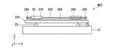
図2は、マスクステージ装置MSTの構成を示す平面図である。図3は、マスクステージ装置MSTの構成を示す側面図である。
図2及び図3に示すように、マスクステージ装置MSTは、上記のマスクホルダ21に加えて、ブラインドベース部材22と、支持部材23とを有している。FIG. 2 is a plan view showing the configuration of the mask stage apparatus MST. FIG. 3 is a side view showing the configuration of the mask stage apparatus MST.
As shown in FIGS. 2 and 3, the mask stage apparatus MST includes a
ブラインドベース部材22は、平面視矩形に形成された板状部材である。ブラインドベース部材22は、X方向に長手となるように形成されている。ブラインドベース部材22は、Y方向に4つ並ぶように配置されている。4つのブラインドベース部材22のうち2つは、マスク保持部の−Y側に配置されている(ブラインドベース部材22A、22C)。残りの2つは、マスク保持部の+Y側に配置されている(ブラインドベース部材22B、22D)。なお、図3では、4つのブラインドベース部材22のうちブラインドベース部材22Aのみ示している。 The
支持部材23は、マスクホルダ21上のうち平面視で上記ブラインドベース部材22A〜22Dに含まれる位置に2つずつ、合計8つ設けられている。各支持部材23は、例えば三角柱状に形成されている。各支持部材23の3つの側面のうち一面がマスクホルダ21に当接している。支持部材23のうち当該一面に対向する辺には、上記4つのブラインドベース部材22が載置されている。当該辺がY方向に平行になるように各支持部材23が配置されている。 A total of eight
ブラインドベース部材22が支持部材23に載置されることにより、当該ブラインドベース部材22は支持部材23に対して+Z方向に拘束されていない状態(非拘束状態)となっている。また、ブラインドベース部材22が三角柱の側辺によって線で支持されていることで、より確実に非拘束状態を維持することができるようになっている。また、支持部材23が1つのブラインドベース部材22について2つずつ設けられているため、各ブラインドベース部材22は、2つの支持部材23上によって2箇所で載置された状態で支持されている。 By placing the
各ブラインドベース部材22(22A〜22D)上には、それぞれプーリ部24と、ガイドレール36とが設けられている。以下の説明において、4つのブラインドベース部材22A〜22Dに設けられる構成要素をブラインドベース部材22A〜22Dごとに識別する場合には、各構成要素の符号にブラインドベース部材22A〜22Dに付されたA〜Dを付記して対応させるものとする。 A
プーリ部24は、各ブラインドベース部材22のX方向上の両端部に一対取り付けられており、θZ方向に回転するようになっている。一対のプーリ部24A、24Cのうちそれぞれの一方(例えば図中左側のプーリ部24A及び24C)は不図示の回転駆動源を有しており、この回転駆動源によりプーリ部自身がθZ方向に回転するようになっている。一対のプーリ部24A、24Cのうちそれぞれの他方(例えば図中右側のプーリ部24A及び24C)及びプーリ部24B、24Dは、このような回転駆動源を有しておらず、外部から回転力が付加されることによってθZ方向に回転するようになっている。 A pair of
各ブラインドベース部材22のプーリ部24には、ワイヤ機構25が掛け渡されている。ワイヤ機構25は、環状に形成されたワイヤ部材26に第1移動部材27及び第2移動部材28が固定された構成になっている。プーリ部24とワイヤ機構25との間は、互いの回転力を伝達し合うようになっている。例えばプーリ部24が回転することでワイヤ機構25が回転するようになっており、ワイヤ機構25が回転することでプーリ部24が回転するようにもなっている。第1移動部材27及び第2移動部材28は、ワイヤ機構25が回転することによって移動するようになっている。 A
ガイドレール36は、ワイヤ機構25の+Y側及び−Y側にそれぞれ1本ずつ設けられている。各ガイドレール36は、第1移動部材27及び第2移動部材28の移動方向(X方向)に沿って平行に形成されている。各ガイドレール36上には、第1移動部材27又は第2移動部材28が載置されている。第1移動部材27及び第2移動部材28は、ワイヤ機構25の回転により、ガイドレール36に沿ってX方向に移動するようになっている。 One
ブラインドベース部材22Aに設けられる第1移動部材27Aと、ブラインドベース部材22Bに設けられる第1移動部材27Bとの間には、遮光部材29が架け渡されている。遮光部材29は、平面視矩形に形成された板状部材であり、Y方向に長手となるように形成されている。遮光部材29は、一方の端部が第1移動部材27Aに固定されており、他方の端部が第1移動部材27Bに固定されている。これら遮光部材29、第1移動部材27A及び第1移動部材27Bは一体的に形成されている。 A
一対のプーリ部24Aのうち回転駆動源を有するプーリ部24Aが回転すると、ワイヤ機構25Aが回転し、第1移動部材27A、第1移動部材27B及び遮光部材29が一体的に移動するようになっている。この場合、第1移動部材27Bの移動によってワイヤ機構25Bが回転し、この回転によってプーリ部24Bが回転するようになっている。 When the
このように、ブラインドベース部材22A側では回転駆動源が設けられているため、ブラインドベース部材22A側の第1移動部材27Aの移動は当該回転駆動源によって主動的な移動となる。また、ブラインドベース部材22B側では回転駆動源が設けられていないため、ブラインドベース部材22B側の第1移動部材27Bの移動は、第1移動部材27A及び遮光部材29の移動に伴った従動的な移動となる。 As described above, since the rotational drive source is provided on the
ブラインドベース部材22Cに設けられる第1移動部材27Cと、ブラインドベース部材22Dに設けられる第1移動部材27Dとの間には、遮光部材30が架け渡されている。遮光部材30は、遮光部材29と同様、平面視矩形に形成された板状部材であり、Y方向が長手に形成されている。遮光部材30は、一方の端部が第1移動部材27Cに固定されており、他方の端部が第1移動部材27Dに固定されている。これら遮光部材30、第1移動部材27C及び第1移動部材27Dは一体的に形成されている。 The
一対のプーリ部24Cのうち回転駆動源を有するプーリ部24Cが回転すると、ワイヤ機構25Cが回転し、第1移動部材27C、第1移動部材27D及び遮光部材30が一体的に移動するようになっている。この場合、第1移動部材27Dの移動によってワイヤ機構25Dが回転し、この回転によってプーリ部24Dが回転するようになっている。 When the
このように、ブラインドベース部材22C側では回転駆動源が設けられているため、ブラインドベース部材22C側の第1移動部材27Cの移動は当該回転駆動源によって主動的な移動となる。また、ブラインドベース部材22D側では回転駆動源が設けられていないため、ブラインドベース部材22D側の第1移動部材27Dの移動は、第1移動部材27C及び遮光部材30の移動に伴った従動的な移動となる。 Thus, since the rotational drive source is provided on the blind base member 22C side, the movement of the first moving
上記の遮光部材29及び遮光部材30は、マスクMに形成されている複数のパターンのうち基板Pに転写しないパターンに露光光が照射されないように遮光する。遮光部材29は、平面視でマスクMの+X側半分の領域上を移動可能になっている。遮光部材30は、平面視でマスクMの−X側半分の領域上を移動可能になっている。これら2つの遮光部材29及び遮光部材30によって、マスクM上の全領域に亘って遮光部材をアクセスさせることができるようになっている。 The
第1移動部材27及び第2移動部材28は、ワイヤ部材26を介して一体的に設けられているため、ワイヤ機構25の回転によりX方向に連動して移動するようになっている。具体的には、第1移動部材27と第2移動部材28とでは、X方向上の逆方向に連動して移動するようになっている。例えば、第1移動部材27が+X方向へ移動すると、第2移動部材28は−X方向へ移動するようになっている。逆に、第1移動部材27が−X方向へ移動すると、第2移動部材28は+X方向へ移動するようになっている。このように、第1移動部材27に連動して当該第1移動部材27とは反対の方向へ移動することにより、第2移動部材28は各ブラインドベース部材22の重心移動を抑制する重心移動抑制部材として機能する。この場合、重心位置はブラインドベース部材22の平面視中央部から移動しないように抑制されるようになっている。 Since the first moving
次に、本実施形態に係る、基板Pの露光時における露光装置EXの動作の一例について説明する。
本実施形態において、露光装置EXの動作の少なくとも一部は、予め定められている露光に関する制御情報(露光制御情報)に基づいて実行される。露光制御情報は、露光装置EXの動作を規定する制御命令群を含み、露光レシピとも呼ばれる。以下の説明において、露光に関する制御情報を適宜「露光レシピ」と表記する。Next, an example of the operation of the exposure apparatus EX during exposure of the substrate P according to the present embodiment will be described.
In the present embodiment, at least a part of the operation of the exposure apparatus EX is executed based on predetermined control information (exposure control information) related to exposure. The exposure control information includes a control command group that defines the operation of the exposure apparatus EX, and is also called an exposure recipe. In the following description, control information related to exposure is referred to as “exposure recipe” as appropriate.
露光レシピは、制御装置CONTに予め記憶されている。少なくとも基板Pの露光時(マスクM及び基板Pに対する露光光ELの照射動作時)における露光装置EXの動作条件は、露光レシピによって予め決定されている。制御装置CONTは、露光レシピに基づいて、露光装置EXの動作を制御する。 The exposure recipe is stored in advance in the control device CONT. The operating conditions of the exposure apparatus EX at least during exposure of the substrate P (during the irradiation operation of the exposure light EL on the mask M and the substrate P) are determined in advance by the exposure recipe. The control device CONT controls the operation of the exposure device EX based on the exposure recipe.
露光レシピは、基板Pの露光時におけるマスクステージ装置MST及び基板ステージ装置PSTの移動条件を含む。基板Pの露光時、制御装置CONTは、露光レシピに基づいて、マスクステージ装置MST及び基板ステージ装置PSTを移動させる。具体的には、基板Pの露光領域PAに含まれる例えば第1領域〜第6領域(不図示)の露光時において、制御装置CONTは、マスクM及び基板PをXY平面内の所定の走査方向に移動させる。制御装置CONTは、露光レシピに基づいて、マスクMと基板Pとを走査方向に同期移動させながらマスクMの下面のマスクパターンMPに露光光ELを照射させる。露光光ELは、マスクパターンMPを介して基板Pの表面の第1領域〜第6領域に照射され、当該第1領域〜第6領域が露光される。 The exposure recipe includes the movement conditions of the mask stage apparatus MST and the substrate stage apparatus PST when the substrate P is exposed. When the substrate P is exposed, the control device CONT moves the mask stage device MST and the substrate stage device PST based on the exposure recipe. Specifically, at the time of exposure of, for example, a first area to a sixth area (not shown) included in the exposure area PA of the substrate P, the control device CONT moves the mask M and the substrate P in a predetermined scanning direction in the XY plane. Move to. Based on the exposure recipe, the control device CONT irradiates the mask pattern MP on the lower surface of the mask M with the exposure light EL while moving the mask M and the substrate P synchronously in the scanning direction. The exposure light EL is irradiated to the first region to the sixth region on the surface of the substrate P through the mask pattern MP, and the first region to the sixth region are exposed.
これら第1領域〜第6領域に対する露光処理を行う際、制御装置CONTは、第1領域〜第6領域を投影領域PR1〜PR7に対して基板Pの表面(XY平面)に沿って走査方向に移動させるとともに、マスクMのマスクパターンMPを照明領域IR1〜IR7に対してマスクMの下面(XY平面)に沿って走査方向に移動させる。本実施形態では、基板Pの走査方向(同期移動方向)を例えばX軸方向とし、マスクMの走査方向(同期移動方向)も例えばX軸方向とする。 When performing the exposure process on the first area to the sixth area, the control device CONT performs the first area to the sixth area in the scanning direction along the surface (XY plane) of the substrate P with respect to the projection areas PR1 to PR7. While moving, the mask pattern MP of the mask M is moved in the scanning direction along the lower surface (XY plane) of the mask M with respect to the illumination regions IR1 to IR7. In the present embodiment, the scanning direction (synchronous movement direction) of the substrate P is, for example, the X-axis direction, and the scanning direction (synchronous movement direction) of the mask M is also, for example, the X-axis direction.
例えば基板Pの第1領域を露光する場合、制御装置CONTは、投影領域PR1〜PR7に対して基板Pの第1領域をX軸方向に移動させると共に、照明領域IR1〜IR7に対してマスクMのマスクパターンMPをX軸方向に移動させる。このとき制御装置CONTは、第1領域のX軸方向への移動とマスクパターンMPのX方向への移動とを同期させる。これに加えて、制御装置CONTは、第1領域及びマスクパターンMPの移動を同期させながら、照明領域IR1〜IR7に露光光ELを照射させる。照射された露光光ELは、マスクMを透過し、投影光学系PLを介して投影領域PR1〜PR7に照射される。基板Pの第1領域は当該露光光ELによって露光され、当該第1領域にはマスクパターンMPのパターンの像が投影される。 For example, when exposing the first region of the substrate P, the control device CONT moves the first region of the substrate P in the X-axis direction with respect to the projection regions PR1 to PR7 and also applies the mask M to the illumination regions IR1 to IR7. The mask pattern MP is moved in the X-axis direction. At this time, the control device CONT synchronizes the movement of the first region in the X-axis direction and the movement of the mask pattern MP in the X direction. In addition to this, the control apparatus CONT irradiates the exposure areas EL1 to IR7 with the exposure light EL while synchronizing the movement of the first area and the mask pattern MP. The irradiated exposure light EL passes through the mask M and is irradiated onto the projection regions PR1 to PR7 through the projection optical system PL. The first area of the substrate P is exposed by the exposure light EL, and a pattern image of the mask pattern MP is projected onto the first area.
制御装置CONTは、第1領域の露光が終了した後、次の露光領域(例えば第2領域)を露光する。このとき制御装置CONTは、投影領域PR1〜PR7が第2領域の露光開始位置に配置されるように基板ステージ装置PSTを移動させる。また、制御装置CONTは、照明領域IR1〜IR7がマスクパターンMPの露光開始位置に配置されるようにマスクステージ装置MSTを移動させる。投影領域PR1〜PR7が第2領域の露光開始位置に配置され、照明領域IR1〜IR7がマスクパターンMPの露光開始位置に配置された後、制御装置CONTは、第2領域の露光を開始する。 After the exposure of the first area is completed, the control device CONT exposes the next exposure area (for example, the second area). At this time, the control device CONT moves the substrate stage device PST so that the projection regions PR1 to PR7 are arranged at the exposure start position of the second region. Further, the control device CONT moves the mask stage device MST so that the illumination regions IR1 to IR7 are arranged at the exposure start position of the mask pattern MP. After the projection areas PR1 to PR7 are arranged at the exposure start position of the second area and the illumination areas IR1 to IR7 are arranged at the exposure start position of the mask pattern MP, the control device CONT starts the exposure of the second area.
このように制御装置CONTは、マスクステージ装置MSTに保持されるマスクMと基板ステージ装置PSTに保持される基板PとをX軸方向に同期移動させながら基板Pに露光光ELを照射させる。加えて、制御装置CONTは、複数の露光領域を露光するため、基板PをXY平面内の所定方向(例えばX軸方向)にステッピング移動させる。制御装置CONTは、これらの露光光照射動作及びステッピング動作を露光領域ごとに繰り返させながら、マスクMに設けられたマスクパターンMP及び投影光学系PLを介して、基板P上の第1領域〜第6領域を順次露光させる。 In this way, the control device CONT irradiates the substrate P with the exposure light EL while synchronously moving the mask M held by the mask stage device MST and the substrate P held by the substrate stage device PST in the X-axis direction. In addition, the control device CONT moves the substrate P in a predetermined direction (for example, the X-axis direction) in the XY plane in order to expose a plurality of exposure regions. The control device CONT repeats the exposure light irradiation operation and the stepping operation for each exposure region, and the first to second regions on the substrate P through the mask pattern MP and the projection optical system PL provided on the mask M. Six areas are sequentially exposed.
制御装置CONTは、一連の露光動作を行わせる際、マスクMに設けられたマスクパターンMPのうち基板Pの所定の露光領域(第1領域〜第6領域)に転写しない部分を適宜遮光させるようにする。制御装置CONTは、遮光部材29及び遮光部材30を用いて当該遮光動作を行わせる。 When performing a series of exposure operations, the control device CONT appropriately shields a portion of the mask pattern MP provided on the mask M that is not transferred to a predetermined exposure region (first region to sixth region) of the substrate P. To. The control device CONT uses the
遮光動作を行わせる際、制御装置CONTは、マスクパターンMPのうち遮光する部分の+Z方向上に遮光部材29又は遮光部材30を配置させる。制御装置CONTは、例えば当該遮光部分がマスクMの−X側半分の領域内に設けられている場合には遮光部材29を移動させ、遮光部分がマスクMの+X側半分の領域内に設けられている場合には遮光部材30を移動させる。 When performing the light shielding operation, the control device CONT arranges the
遮光部材29又は遮光部材30を移動させる際、制御装置CONTは、マスクパターンMPのうち遮光する部分のX座標を例えば露光レシピに基づいて確認し、当該X座標に対応する遮光部材29又は遮光部材30を選択する。ここでは、例えば遮光部材29を選択するものとする。 When the
遮光部材29を選択した後、制御装置CONTは、ブラインドベース部材22Aに設けられる回転駆動源を駆動させ、プーリ部24Aを回転させる。プーリ部24Aの回転により、当該プーリ部24Aに掛け回されたワイヤ機構25Aが回転する。ワイヤ機構25Aの回転によって第1移動部材27Aが移動し、第1移動部材27Aの移動に伴って第1移動部材27B及び遮光部材29が移動する。 After selecting the
図4及び図5は、第1移動部材27A、第2移動部材27B及び遮光部材29が移動したときの様子を示す図である。図4は図2に対応する平面図であり、図5は図3に対応する側面図である。例えば遮光部材29が図4及び図5に示す位置まで移動した場合、遮光部材29、第1移動部材27A及び第2移動部材28Aがブラインドベース部材22A上のX方向中央部に集まることになる。図5に示す状態においてはブラインドベース部材22AのX方向中央部に荷重が集中して作用する。このため、例えば遮光部材29がブラインドベース部材22の状態に比べてブラインドベース部材22AはX方向中央部が−Z方向に撓むように変形する。 4 and 5 are diagrams illustrating a state when the first moving
ブラインドベース部材22Aがマスクホルダ21に対して固定されている場合、ブラインドベース部材22Aの変形のモーメントは両者の固定位置を介してマスクホルダ21に伝達され、マスクホルダ21が変形する。マスクホルダ21が変形すると、マスクホルダ21のマスク保持部に保持されるマスクM及び移動鏡14も変形してしまう場合がある。マスクMが変形すると、当該マスクMを介して転写されるパターンの像が歪んでしまい、露光精度に悪影響を及ぼすこととなる。また、移動鏡14が変形すると、パターンの像が基板P上の所望の位置に転写されず、露光精度が悪化することとなる。 When the
一方、本実施形態では、ブラインドベース部材22Aがマスクホルダ21に対して固定されてはおらず、ブラインドベース部材22Aが支持部材23に載置されているだけの構成となっている。このため、ブラインドベース部材22Aの変形のモーメントはマスクホルダ21にはほとんど伝達されず、ブラインドベース部材22Aのみが変形する。マスクホルダ21の変形が抑制されることになるため、マスクホルダ21に保持されるマスクM及び移動鏡14の変形も抑制される。 On the other hand, in the present embodiment, the
ここで、ブラインドベース部材22Aの変形により、例えば遮光部材29のX座標が変化する場合も考えられる。これに対しては、例えばブラインドベース部材22Aの変形の前後における遮光部材29のX座標の変化量を求めておき、制御装置CONTが当該変化量を考慮したX座標位置に遮光部材29を移動させるよう制御すれば良い。 Here, for example, the X coordinate of the
なお、露光動作において制御装置CONTが遮光部材30を選択して移動させる場合であっても、上記のように遮光部材29を選択して移動させる場合と同様の説明が可能である。 Even when the control device CONT selects and moves the
以上のように、本実施形態によれば、ブラインドベース部材22とマスクホルダ21との間がブラインドベース部材22の荷重方向の対向方向に関して非拘束状態になっているため、両者が拘束状態になっている場合に比べて、ブラインドベース部材22の変形によるモーメントがマスクホルダ21に伝わりにくくなる。このため、第1移動部材27、第2移動部材28、遮光部材29及び遮光部材30の移動によってブラインドベース部材22が変形する場合であっても、当該ブラインドベース部材22の変形に伴うマスクホルダ21の変形が抑えられる。これにより、マスクM及び移動鏡14の変形を抑えることができる。 As described above, according to the present embodiment, the space between the
また、本実施形態によれば、第2移動部材28が、ブラインドベース部材22上の構成要素(第1移動部材27、第2移動部材28、遮光部材29及び30)の重心移動を抑制するようになっているため、ブラインドベース部材22の重心を安定させることができる。本実施形態では、ブラインドベース部材22のうち上記各構成要素の移動方向であるX方向上の2箇所でブラインドベース部材22を支持する構成となっているため、2箇所の支持部材23への負荷が変化するのを抑制することができる。 Further, according to the present embodiment, the second moving
本発明の技術範囲は上記実施形態に限定されるものではなく、本発明の趣旨を逸脱しない範囲で適宜変更を加えることができる。
例えば、上記実施形態の構成に加えて、ブラインドベース部材22のX方向及びY方向の移動を規制する規制部材を配置した構成であっても構わない。図6(a)はブラインドベース部材22の構成を示す平面図であり、図6(b)はブラインドベース部材22の構成を示す断面図である。図6(a)及び図6(b)に示すように、上記の規制部材としてはX方向の移動を弾性的に規制する板バネ部材31や、Y方向及びθZ方向の移動を弾性的に規制するピン部材32などが挙げられる。The technical scope of the present invention is not limited to the above-described embodiment, and appropriate modifications can be made without departing from the spirit of the present invention.
For example, in addition to the configuration of the above-described embodiment, a configuration in which a regulating member that regulates the movement of the
板バネ部材31は、ブラインドベース部材22の−X方向の端面及び+X方向の端面にそれぞれの一端が取り付けられている。板バネ部材31の他端はマスクホルダ21のX方向の両端部に支柱部材33を介してそれぞれ固定されている。支柱部材33は、例えばビスなどの固定部材によってマスクホルダ21に固定されている。 The
ピン部材32は、例えばブラインドベース部材22のうちプーリ部24に対して端部側の位置に1つずつ設けられている。ブラインドベース部材22のうちピン部材32の設けられる部分には貫通孔34が形成されている。2つの貫通孔34のうち例えば−X側に設けられる貫通孔34は、平面視でX方向に広がるように形成されている。この構成により、ブラインドベース部材22が変形したときのマージンを確保することができるようになっている。この貫通孔34については、例えばブラインドベース部材22の−Z側から+Z側にかけて徐々に孔径が大きくなるようにテーパー状に形成しても構わない。 For example, one
また、上記実施形態においては、ブラインドベース部材22上の可動部(第1移動部材27、第2移動部材28、遮光部材29及び遮光部材30)を移動させる構成として、プーリ部24及びワイヤ機構25を例に挙げて説明したが、これに限られることは無く、例えばモータ及びボールネジを用いた構成、リニアモータやエアベアリングなど、他のアクチュエータを用いる構成としても構わない。 Moreover, in the said embodiment, the
また、上記実施形態においては、ブラインドベース部材22の2箇所を支持するように各ブラインドベース部材22について支持部材23を2つずつ配置する構成としたが、これに限られることは無く、例えば3つ以上配置する構成とすることもできる。ただし、ブラインドベース部材22の変形に起因するマスクホルダ21の変形を抑制する観点では、各ブラインドベース部材22(22A〜22D)を2箇所で支持することが好ましい。 Moreover, in the said embodiment, although it was set as the structure which arrange | positions two
また、支持部材23の形状としては、上記実施形態のように三角柱形状には限られず、例えば他の多角柱形状に構成して線若しくは面で支持する構成であっても構わないし、例えば円錐形状又は角錐形状に形成して点で支持する構成としても構わない。 Further, the shape of the
なお、上述の実施形態の基板Pとしては、半導体デバイス製造用の半導体ウエハのみならず、ディスプレイデバイス用のガラス基板、薄膜磁気ヘッド用のセラミックウエハ、あるいは露光装置で用いられるマスクまたはレチクルの原版(合成石英、シリコンウエハ)等が適用される。 As the substrate P in the above-described embodiment, not only a semiconductor wafer for manufacturing a semiconductor device but also a glass substrate for a display device, a ceramic wafer for a thin film magnetic head, or an original mask (reticle) used in an exposure apparatus ( Synthetic quartz, silicon wafer) or the like is applied.
なお、上述の実施形態においては、露光装置EXが、マスクMと基板Pとを同期移動してマスクMのマスクパターンMPの像を基板Pに投影するステップ・アンド・スキャン方式の走査型露光装置(スキャニングステッパ)である場合を例にして説明したが、マスクMと基板Pとを静止した状態でマスクMのマスクパターンMPの像を一括投影し、基板Pを順次ステップ移動させるステップ・アンド・リピート方式の投影露光装置(ステッパ)にも適用することができる。 In the above-described embodiment, the exposure apparatus EX is a step-and-scan type scanning exposure apparatus that projects the mask pattern MP image of the mask M onto the substrate P by moving the mask M and the substrate P synchronously. (Scanning stepper) has been described by way of example, but the mask pattern MP image of the mask M is collectively projected while the mask M and the substrate P are stationary, and the substrate P is sequentially moved step by step. The present invention can also be applied to a repeat type projection exposure apparatus (stepper).
露光装置EXの種類としては、液晶表示素子製造用又はフラットパネルディスプレイ製造用の露光装置に限られず、感光基板に半導体素子パターンを露光する半導体素子製造用の露光装置や、薄膜磁気ヘッド、撮像素子(CCD)、マイクロマシン、MEMS、DNAチップ、あるいはレチクル又はマスクなどを製造するための露光装置などにも広く適用できる。 The type of the exposure apparatus EX is not limited to an exposure apparatus for manufacturing a liquid crystal display element or a flat panel display. An exposure apparatus for manufacturing a semiconductor element that exposes a semiconductor element pattern on a photosensitive substrate, a thin film magnetic head, and an image sensor (CCD), micromachine, MEMS, DNA chip, or an exposure apparatus for manufacturing a reticle or mask can be widely applied.
上述の実施形態の露光装置EXは、本願請求の範囲に挙げられた各構成要素を含む各種サブシステムを、所定の機械的精度、電気的精度、光学的精度を保つように、組み立てることで製造される。これら各種精度を確保するために、この組み立ての前後には、各種光学系については光学的精度を達成するための調整、各種機械系については機械的精度を達成するための調整、各種電気系については電気的精度を達成するための調整が行われる。
各種サブシステムから露光装置への組み立て工程は、各種サブシステム相互の、機械的接続、電気回路の配線接続、気圧回路の配管接続等が含まれる。この各種サブシステムから露光装置への組み立て工程の前に、各サブシステム個々の組み立て工程があることはいうまでもない。各種サブシステムの露光装置への組み立て工程が終了したら、総合調整が行われ、露光装置全体としての各種精度が確保される。なお、露光装置の製造は温度およびクリーン度等が管理されたクリーンルームで行うことが望ましい。The exposure apparatus EX of the above-described embodiment is manufactured by assembling various subsystems including the respective constituent elements recited in the claims of the present application so as to maintain predetermined mechanical accuracy, electrical accuracy, and optical accuracy. Is done. In order to ensure these various accuracies, before and after assembly, various optical systems are adjusted to achieve optical accuracy, various mechanical systems are adjusted to achieve mechanical accuracy, and various electrical systems are Adjustments are made to achieve electrical accuracy.
The assembly process from the various subsystems to the exposure apparatus includes mechanical connection, electrical circuit wiring connection, pneumatic circuit piping connection and the like between the various subsystems. Needless to say, there is an assembly process for each subsystem before the assembly process from the various subsystems to the exposure apparatus. When the assembly process of the various subsystems to the exposure apparatus is completed, comprehensive adjustment is performed to ensure various accuracies as the entire exposure apparatus. The exposure apparatus is preferably manufactured in a clean room where the temperature, cleanliness, etc. are controlled.
半導体デバイス等のマイクロデバイスは、図7に示すように、マイクロデバイスの機能・性能設計を行うステップ201、この設計ステップに基づいたマスク(レチクル)を製作するステップ202、デバイスの基材である基板を製造するステップ203、上述の実施形態に従って、マスクのパターンを用いて露光光で基板を露光すること、及び露光された基板を現像することを含む基板処理(露光処理)を含む基板処理ステップ204、デバイス組み立てステップ(ダイシング工程、ボンディング工程、パッケージ工程などの加工プロセスを含む)205、検査ステップ206等を経て製造される。 As shown in FIG. 7, a microdevice such as a semiconductor device includes a
EX…露光装置 M…マスク MST…マスクステージ装置 PST…基板ステージ装置 CONT…制御装置 14…移動鏡 21…マスクホルダ 22(22A〜22D)…ブラインドベース部材 23…支持部材 24…プーリ部 25(25A〜25D)…ワイヤ機構 27(27A〜27D)…移動部材 28(28A〜28D)…移動部材 29、30…遮光部材 31…板バネ部材 32…ピン部材 EX ... Exposure apparatus M ... Mask MST ... Mask stage apparatus PST ... Substrate stage apparatus CONT ...
Claims (12)
Translated fromJapanese前記第1ベース部に対して移動可能な可動部を保持する第2ベース部と、
前記第1ベース部上に設けられ、前記第2ベース部の荷重方向に対向する対向方向に関して非拘束状態で該第2ベース部を支持するベース支持部と、
を備え、
前記可動部は、前記荷重方向と直交する所定方向に移動可能な第1移動部材と、該第1移動部材の前記所定方向の一方側への移動に連動して前記所定方向の他方側へ移動する第2移動部材と、を含み、
前記ベース支持部は、前記所定方向の2箇所で前記第2ベース部を支持することを特徴とするステージ装置。A first base for holding an object;
A second base part holding a movable part movable relative to the first base part;
A base support portion provided on the first base portion and supporting the second base portion in an unconstrained state with respect to a facing direction opposite to a load direction of the second base portion;
Equipped witha,
The movable portion moves to the other side of the predetermined direction in conjunction with a first moving member movable in a predetermined direction orthogonal to the load direction and the movement of the first moving member to one side of the predetermined direction. A second moving member that includes:
The stagesupport device, wherein the base support part supports the second base part at two locations in the predetermined direction .
前記可動部は、前記第1移動部材に接続され前記所定方向に移動可能に設けられた前記照明光を遮光する遮光部材を有することを特徴とする請求項1から請求項4のうちいずれか一項に記載のステージ装置。The object has a plurality of pattern areas and the pattern areas are illuminated by illumination light.
The said movable part has a light-shielding member which shieldsthe said illumination lightprovided so that it could move to the said predetermined direction connected to the said 1st moving member, The any one of Claims1-4 characterizedby the above-mentioned. The stage apparatus according to item.
感光剤が設けられた基板を保持する基板ステージと、
前記パターンを介して前記基板に露光光を照射する照射系と、
を備えることを特徴とする露光装置。The stage apparatus according to any one of claims 1 to 9, which holds an object provided with a pattern;
A substrate stage for holding a substrate provided with a photosensitive agent;
An irradiation system for irradiating the substrate with exposure light through the pattern;
An exposure apparatus comprising:
前記パターンが転写された前記感光剤を現像して、前記パターンに対応する露光パターン層を形成することと、
前記露光パターン層を介して前記基板を加工することと、
を含むデバイス製造方法。Using the exposure apparatus according toclaim 10or 11 ,transferring apattern to the substrate;
Developing the photosensitive agent having thepattern transferred thereon to form an exposure pattern layer corresponding to the pattern;
Processing the substrate through the exposed pattern layer;
A device manufacturing method including:
Priority Applications (1)
| Application Number | Priority Date | Filing Date | Title |
|---|---|---|---|
| JP2008310742AJP5375057B2 (en) | 2008-12-05 | 2008-12-05 | Stage apparatus, exposure apparatus, and device manufacturing method |
Applications Claiming Priority (1)
| Application Number | Priority Date | Filing Date | Title |
|---|---|---|---|
| JP2008310742AJP5375057B2 (en) | 2008-12-05 | 2008-12-05 | Stage apparatus, exposure apparatus, and device manufacturing method |
Publications (2)
| Publication Number | Publication Date |
|---|---|
| JP2010135596A JP2010135596A (en) | 2010-06-17 |
| JP5375057B2true JP5375057B2 (en) | 2013-12-25 |
Family
ID=42346581
Family Applications (1)
| Application Number | Title | Priority Date | Filing Date |
|---|---|---|---|
| JP2008310742AActiveJP5375057B2 (en) | 2008-12-05 | 2008-12-05 | Stage apparatus, exposure apparatus, and device manufacturing method |
Country Status (1)
| Country | Link |
|---|---|
| JP (1) | JP5375057B2 (en) |
Family Cites Families (6)
| Publication number | Priority date | Publication date | Assignee | Title |
|---|---|---|---|---|
| JP3209294B2 (en)* | 1993-02-01 | 2001-09-17 | 株式会社ニコン | Exposure equipment |
| TWI338323B (en)* | 2003-02-17 | 2011-03-01 | Nikon Corp | Stage device, exposure device and manufacguring method of devices |
| JP2004273666A (en)* | 2003-03-07 | 2004-09-30 | Nikon Corp | Exposure equipment |
| TW200507066A (en)* | 2003-07-25 | 2005-02-16 | Nikon Corp | Exposure apparatus |
| JP2006120798A (en)* | 2004-10-20 | 2006-05-11 | Canon Inc | Exposure equipment |
| JP2007123332A (en)* | 2005-10-25 | 2007-05-17 | Nikon Corp | Stage apparatus, exposure apparatus, and device manufacturing method |
- 2008
- 2008-12-05JPJP2008310742Apatent/JP5375057B2/enactiveActive
Also Published As
| Publication number | Publication date |
|---|---|
| JP2010135596A (en) | 2010-06-17 |
Similar Documents
| Publication | Publication Date | Title |
|---|---|---|
| TWI628518B (en) | Exposure apparatus and exposure method, and component manufacturing method | |
| US11126094B2 (en) | Exposure apparatus, manufacturing method of flat-panel display, device manufacturing method, and exposure method | |
| US20180239264A1 (en) | Movable body apparatus, exposure apparatus and device manufacturing method | |
| US20120064461A1 (en) | Movable body apparatus, exposure apparatus, device manufacturing method, flat-panel display manufacturing method, and object exchange method | |
| TWI728425B (en) | Movable body apparatus, exposure apparatus, manufacturing method of flat panel display, and device manufacturing method | |
| TWI784440B (en) | Exposure apparatus, manufacturing method of flat panel display, device manufacturing method, and exposure method | |
| TW201643556A (en) | Exposure apparatus, manufacturing method of flat panel display, device manufacturing method, and exposure method | |
| US10935894B2 (en) | Movable body apparatus, exposure apparatus, manufacturing method of flat-panel display and device manufacturing method, and movement method of object | |
| JPWO2017057587A1 (en) | Exposure apparatus, flat panel display manufacturing method, and device manufacturing method | |
| TWI772329B (en) | Movable body apparatus, moving method, exposure apparatus, exposure method, manufacturing method of flat panel display, and device manufacturing method | |
| CN108139689A (en) | Exposure apparatus, exposure method, and flat-panel display manufacturing method | |
| TWI841764B (en) | Movable body apparatus, exposure apparatus, manufacturing method of flat panel display and device manufacturing method, and measurement method | |
| KR102320293B1 (en) | A moving body apparatus, a moving method, an exposure apparatus, an exposure method, a manufacturing method of a flat panel display, and a device manufacturing method | |
| JP6855008B2 (en) | Exposure equipment, flat panel display manufacturing method, device manufacturing method, and exposure method | |
| TW201723680A (en) | Movable body apparatus, exposure apparatus, flat-panel display manufacturing method, and device manufacturing method | |
| JP5375057B2 (en) | Stage apparatus, exposure apparatus, and device manufacturing method | |
| KR102318643B1 (en) | A movable body apparatus, a moving method, an exposure apparatus, an exposure method, a manufacturing method of a flat panel display, and a device manufacturing method | |
| JP2010267806A (en) | Stage apparatus, cable holding apparatus, exposure apparatus, and device manufacturing method | |
| WO2010113525A1 (en) | Exposure apparatus, exposure method and device manufacturing method | |
| JP2010200452A (en) | Motor device, stage device, and aligner | |
| JP2010217389A (en) | Exposure apparatus, exposure method, and method for manufacturing device | |
| JP2010026398A (en) | Mask substrate, mask blank, exposure method, and method for manufacturing device | |
| JP2010016111A (en) | Exposure apparatus and device manufacturing method | |
| WO2010082475A1 (en) | Stage equipment, exposure equipment, exposure method and device manufacturing method | |
| JP2010197958A (en) | Exposing method, and device manufacturing method |
Legal Events
| Date | Code | Title | Description |
|---|---|---|---|
| A621 | Written request for application examination | Free format text:JAPANESE INTERMEDIATE CODE: A621 Effective date:20111205 | |
| A521 | Request for written amendment filed | Free format text:JAPANESE INTERMEDIATE CODE: A523 Effective date:20120627 | |
| A977 | Report on retrieval | Free format text:JAPANESE INTERMEDIATE CODE: A971007 Effective date:20121128 | |
| A131 | Notification of reasons for refusal | Free format text:JAPANESE INTERMEDIATE CODE: A131 Effective date:20130108 | |
| A521 | Request for written amendment filed | Free format text:JAPANESE INTERMEDIATE CODE: A523 Effective date:20130311 | |
| TRDD | Decision of grant or rejection written | ||
| A01 | Written decision to grant a patent or to grant a registration (utility model) | Free format text:JAPANESE INTERMEDIATE CODE: A01 Effective date:20130827 | |
| A61 | First payment of annual fees (during grant procedure) | Free format text:JAPANESE INTERMEDIATE CODE: A61 Effective date:20130909 | |
| R150 | Certificate of patent or registration of utility model | Ref document number:5375057 Country of ref document:JP Free format text:JAPANESE INTERMEDIATE CODE: R150 Free format text:JAPANESE INTERMEDIATE CODE: R150 | |
| R250 | Receipt of annual fees | Free format text:JAPANESE INTERMEDIATE CODE: R250 | |
| R250 | Receipt of annual fees | Free format text:JAPANESE INTERMEDIATE CODE: R250 | |
| R250 | Receipt of annual fees | Free format text:JAPANESE INTERMEDIATE CODE: R250 | |
| R250 | Receipt of annual fees | Free format text:JAPANESE INTERMEDIATE CODE: R250 | |
| R250 | Receipt of annual fees | Free format text:JAPANESE INTERMEDIATE CODE: R250 | |
| R250 | Receipt of annual fees | Free format text:JAPANESE INTERMEDIATE CODE: R250 | |
| R250 | Receipt of annual fees | Free format text:JAPANESE INTERMEDIATE CODE: R250 | |
| R250 | Receipt of annual fees | Free format text:JAPANESE INTERMEDIATE CODE: R250 | |
| R250 | Receipt of annual fees | Free format text:JAPANESE INTERMEDIATE CODE: R250 | |
| R250 | Receipt of annual fees | Free format text:JAPANESE INTERMEDIATE CODE: R250 |