JP5375032B2 - Non-contact power transmission device and design method of non-contact power transmission device - Google Patents
Non-contact power transmission device and design method of non-contact power transmission deviceDownload PDFInfo
- Publication number
- JP5375032B2 JP5375032B2JP2008283563AJP2008283563AJP5375032B2JP 5375032 B2JP5375032 B2JP 5375032B2JP 2008283563 AJP2008283563 AJP 2008283563AJP 2008283563 AJP2008283563 AJP 2008283563AJP 5375032 B2JP5375032 B2JP 5375032B2
- Authority
- JP
- Japan
- Prior art keywords
- coil
- frequency
- resonance
- impedance
- primary coil
- Prior art date
- Legal status (The legal status is an assumption and is not a legal conclusion. Google has not performed a legal analysis and makes no representation as to the accuracy of the status listed.)
- Expired - Fee Related
Links
Images


Classifications
- H—ELECTRICITY
- H02—GENERATION; CONVERSION OR DISTRIBUTION OF ELECTRIC POWER
- H02J—CIRCUIT ARRANGEMENTS OR SYSTEMS FOR SUPPLYING OR DISTRIBUTING ELECTRIC POWER; SYSTEMS FOR STORING ELECTRIC ENERGY
- H02J50/00—Circuit arrangements or systems for wireless supply or distribution of electric power
- H02J50/40—Circuit arrangements or systems for wireless supply or distribution of electric power using two or more transmitting or receiving devices
- H02J50/402—Circuit arrangements or systems for wireless supply or distribution of electric power using two or more transmitting or receiving devices the two or more transmitting or the two or more receiving devices being integrated in the same unit, e.g. power mats with several coils or antennas with several sub-antennas
- G—PHYSICS
- G06—COMPUTING OR CALCULATING; COUNTING
- G06F—ELECTRIC DIGITAL DATA PROCESSING
- G06F30/00—Computer-aided design [CAD]
- G06F30/30—Circuit design
- G06F30/36—Circuit design at the analogue level
- H—ELECTRICITY
- H02—GENERATION; CONVERSION OR DISTRIBUTION OF ELECTRIC POWER
- H02J—CIRCUIT ARRANGEMENTS OR SYSTEMS FOR SUPPLYING OR DISTRIBUTING ELECTRIC POWER; SYSTEMS FOR STORING ELECTRIC ENERGY
- H02J50/00—Circuit arrangements or systems for wireless supply or distribution of electric power
- H02J50/10—Circuit arrangements or systems for wireless supply or distribution of electric power using inductive coupling
- H02J50/12—Circuit arrangements or systems for wireless supply or distribution of electric power using inductive coupling of the resonant type
- H—ELECTRICITY
- H04—ELECTRIC COMMUNICATION TECHNIQUE
- H04B—TRANSMISSION
- H04B5/00—Near-field transmission systems, e.g. inductive or capacitive transmission systems
- H04B5/20—Near-field transmission systems, e.g. inductive or capacitive transmission systems characterised by the transmission technique; characterised by the transmission medium
- H04B5/24—Inductive coupling
- H04B5/26—Inductive coupling using coils
- H04B5/266—One coil at each side, e.g. with primary and secondary coils
- H—ELECTRICITY
- H04—ELECTRIC COMMUNICATION TECHNIQUE
- H04B—TRANSMISSION
- H04B5/00—Near-field transmission systems, e.g. inductive or capacitive transmission systems
- H04B5/70—Near-field transmission systems, e.g. inductive or capacitive transmission systems specially adapted for specific purposes
- H04B5/79—Near-field transmission systems, e.g. inductive or capacitive transmission systems specially adapted for specific purposes for data transfer in combination with power transfer
- H—ELECTRICITY
- H01—ELECTRIC ELEMENTS
- H01F—MAGNETS; INDUCTANCES; TRANSFORMERS; SELECTION OF MATERIALS FOR THEIR MAGNETIC PROPERTIES
- H01F38/00—Adaptations of transformers or inductances for specific applications or functions
- H01F38/14—Inductive couplings
Landscapes
- Engineering & Computer Science (AREA)
- Computer Networks & Wireless Communication (AREA)
- Computer Hardware Design (AREA)
- Theoretical Computer Science (AREA)
- Physics & Mathematics (AREA)
- Signal Processing (AREA)
- Power Engineering (AREA)
- Evolutionary Computation (AREA)
- General Physics & Mathematics (AREA)
- General Engineering & Computer Science (AREA)
- Geometry (AREA)
- Charge And Discharge Circuits For Batteries Or The Like (AREA)
- Current-Collector Devices For Electrically Propelled Vehicles (AREA)
Description
Translated fromJapanese本発明は、非接触電力伝送装置及び非接触電力伝送装置の設計方法に関する。 The present invention relates to a contactless power transmission device and a method for designing a contactless power transmission device.
図6に示すように、二つの銅線コイル51,52を離れた状態で配置し、一方の銅線コイル51から他方の銅線コイル52に電磁場の共鳴によって電力を伝送することが紹介されている(例えば、非特許文献1及び特許文献1参照)。具体的には、交流電源53に接続された1次コイル54で発生した磁場を銅線コイル51,52による磁場共鳴により増強し、2次コイル55により増強された銅線コイル52付近の磁場から電磁誘導を利用して電力を取り出し負荷56に供給する。そして、半径30cmの銅線コイル51,52を2m離して配置した場合に、負荷56としての60Wの電灯を点灯できることが確認されている。
この非接触電力伝送装置において交流電源の電力を負荷に効率良く供給するには、交流電源から電力を効率良く共鳴系に供給することが必要になる。しかし、従来技術には非接触電力伝送装置の概要が記載されているだけで、具体的にどのようにすればそのような条件を満足できる非接触電力伝送装置を得ることができるのかに付いては記載されていない。 In this contactless power transmission device, in order to efficiently supply the power of the AC power source to the load, it is necessary to efficiently supply the power from the AC power source to the resonance system. However, only the outline of the non-contact power transmission device is described in the prior art, and how the non-contact power transmission device that can satisfy such conditions can be obtained specifically. Is not listed.
本発明は、前記従来の問題に鑑みてなされたものであって、その目的は、交流電源から電力を効率良く共鳴系に供給することができる非接触電力伝送装置及びその設計方法を提供することにある。 The present invention has been made in view of the above-described conventional problems, and an object thereof is to provide a non-contact power transmission apparatus that can efficiently supply power from an AC power source to a resonance system and a design method thereof. It is in.
前記の目的を達成するため、請求項1及び2に記載の発明は、交流電源から交流電圧が印加される1次コイルと、1次側共鳴コイルと、2次側共鳴コイルと、負荷が接続される2次コイルとを有する共鳴系を備える非接触電力伝送装置である。そして、前記1次コイルのインピーダンスが、前記交流電源の出力インピーダンスと前記共鳴系の入力インピーダンスとが整合するように設定されている。ここで、「交流電源」とは、交流電圧を出力する電源を意味し、直流電源から入力された直流を交流に変換して出力するものも含む。また、「共鳴系の入力インピーダンス」とは、1次コイルの両端で測定した共鳴系全体のインピーダンスを指す。このとき、2次コイルに接続される負荷の有無は問わない。さらに、「交流電源の出力インピーダンスと共鳴系の入力インピーダンスとが整合する」とは、両インピーダンスが完全に一致することだけでなく、非接触電力伝送装置として所望の性能(電力伝送効率等)を達成する範囲内で、例えば、共鳴系の入力インピーダンスと交流電源の出力インピーダンスとの差が、交流電源の出力インピーダンスに対して±10%の範囲内、好ましくは±5%の範囲内であることも意味する。In order to achieve the above object, according to thefirst and second aspects of the present invention, a primary coil to which an AC voltage is applied from an AC power source, a primary side resonance coil, a secondary side resonance coil, and a load are connected. It is a non-contact electric power transmission apparatus provided with the resonance system which has a secondary coil. The impedance of the primary coil is set so that the output impedance of the AC power supply matches the input impedance of the resonance system. Here, the “AC power supply” means a power supply that outputs an AC voltage, and includes an output that converts a DC input from a DC power supply into an AC. The “resonance system input impedance” refers to the impedance of the entire resonance system measured at both ends of the primary coil. At this time, it does not matter whether there is a load connected to the secondary coil. Furthermore, “the output impedance of the AC power supply and the input impedance of the resonance system are matched” not only means that both impedances completely match, but also the desired performance (power transmission efficiency, etc.) as a non-contact power transmission device. Within the range to be achieved, for example, the difference between the input impedance of the resonance system and the output impedance of the AC power supply is within ± 10%, preferably ± 5% of the output impedance of the AC power supply. Also means.
これらの発明では、交流電源の出力インピーダンスと共鳴系の入力インピーダンスとが整合されているため、交流電源から効率良く電力を共鳴系に供給することができる。
特に、請求項1に記載の発明は、前記交流電源は、前記共鳴系の入力インピーダンスと周波数との関係をグラフにした場合の極大点と極小点との間に存在するインピーダンスに対応する周波数の交流電圧を前記1次コイルに印加する。この発明では、1次コイルに供給された電力を効率良く負荷に伝送できる。In these inventions, since the output impedance of the AC power supply and the input impedance of the resonance system are matched, power can be efficiently supplied from the AC power supply to the resonance system.
In particular, the invention according to
特に、請求項2に記載の発明は、前記交流電源は、前記共鳴系の入力インピーダンスが周波数の増加に伴い減少する範囲内の周波数の交流電圧を前記1次コイルに印加する。この発明では、1次コイルに供給された電力を効率良く負荷に伝送できる。In particular, the invention described inclaim2,prior Symbol AC power supply applies an alternating voltage of a frequency in the range where the input impedance of the resonant system is decreased with increasing frequency to the primary coil. In this invention, the electric power supplied to the primary coil can be efficiently transmitted to the load.
請求項3及び4に記載の発明は、交流電源から交流電圧が印加される1次コイルと、1次側共鳴コイルと、2次側共鳴コイルと、負荷が接続される2次コイルとを有する共鳴系を備える非接触電力伝送装置の設計方法である。そして、前記交流電源から前記1次コイルへ印加する交流電圧の周波数を設定した後、当該周波数で前記交流電源の出力インピーダンスと前記共鳴系の入力インピーダンスとが整合するように前記1次コイルのインピーダンスを設定する。The invention described inclaims 3 and 4 includes a primary coil to which an AC voltage is applied from an AC power source, a primary side resonance coil, a secondary side resonance coil, and a secondary coil to which a load is connected. It is a design method of a non-contact power transmission device including a resonance system. Then, after setting the frequency of the AC voltage applied from the AC power source to the primary coil, the impedance of the primary coil is set so that the output impedance of the AC power source matches the input impedance of the resonance system at the frequency. Set.
これらの発明は、実験を通して発明者らが得た「1次コイルのインピーダンスを変えても共鳴系全体の電力伝送特性に影響を及ぼさない」との知見に基づく。すなわち、非接触電力伝送装置を設計する際に、先ず共鳴系の電力伝送特性(例えば、電力伝送効率が最大となる周波数)に基づき、交流電源から1次コイルに印加される交流電圧の周波数が設定される。次にその周波数で交流電源の出力インピーダンスと共鳴系の入力インピーダンスとが整合(マッチング)するように1次コイルのインピーダンスが設定される。このとき、1次コイルのインピーダンスを変えても共鳴系の電力伝送特性には影響を及ぼさないので、整合後に再度共鳴系や交流電源の交流周波数等を調整する必要がない。したがって、交流電源から効率良く共鳴系に電力を供給できる非接触電力伝送装置を提供できる。また、交流電源の出力インピーダンスと共鳴系の入力インピーダンスとの整合も容易になる。These inventions are based on the knowledge that the inventors obtained through experiments that "changing the impedance of the primary coil does not affect the power transmission characteristics of the entire resonance system". That is, when designing a non-contact power transmission device, first, the frequency of the AC voltage applied from the AC power source to the primary coil is determined based on the resonance power transmission characteristics (for example, the frequency at which the power transmission efficiency is maximized). Is set. Next, the impedance of the primary coil is set so that the output impedance of the AC power supply matches the input impedance of the resonance system at that frequency. At this time, even if the impedance of the primary coil is changed, it does not affect the power transmission characteristics of the resonance system, so that it is not necessary to adjust the resonance frequency or the AC frequency of the AC power source again after the matching. Therefore, it is possible to provide a non-contact power transmission device that can efficiently supply power from the AC power source to the resonance system. In addition, matching between the output impedance of the AC power supply and the input impedance of the resonance system is facilitated.
特に、請求項3に記載の発明は、前記交流電源から前記1次コイルに印加する交流電圧の周波数として、前記共鳴系の入力インピーダンスと周波数との関係を調べて入力インピーダンスと周波数との関係をグラフにした場合の極大点と極小点との間の周波数を採用する。この発明では、1次コイルに供給された電力を効率良く負荷に伝送できる。In particular, the invention described inclaim3,prior SL as the frequency of the AC voltage applied to the primary coil from the AC power source, the relationship between the input impedance and frequency by examining the relationship between the input impedance and the frequency of the resonant system The frequency between the maximum point and the minimum point in the case of a graph is adopted. In this invention, the electric power supplied to the primary coil can be efficiently transmitted to the load.
特に、請求項4に記載の発明は、前記交流電源から前記1次コイルに印加する交流電圧の周波数として、前記共鳴系の入力インピーダンスが周波数の増加に伴い減少する範囲内の周波数を採用する。この発明では、1次コイルに供給された電力を効率良く負荷に伝送できる。In particular, the invention described inclaim4, as the frequency of the AC voltage applied from theprevious SL AC power to the primary coil, the input impedance of the resonant system adopts a frequency within the range decreases with increasing frequency . In this invention, the electric power supplied to the primary coil can be efficiently transmitted to the load.
本発明によれば、交流電源から電力を効率良く共鳴系に供給することができる。 ADVANTAGE OF THE INVENTION According to this invention, electric power can be efficiently supplied to a resonance system from AC power supply.
以下、本発明を具体化した一実施形態を図1〜図4にしたがって説明する。
図1に示すように、非接触電力伝送装置10は、交流電源11から供給される電力を非接触で伝送する共鳴系12を備える。共鳴系12は、交流電源11に接続される1次コイル13と、1次側共鳴コイル14と、2次側共鳴コイル15と、2次コイル16とを有する。2次コイル16は負荷17に接続されている。Hereinafter, an embodiment embodying the present invention will be described with reference to FIGS.
As shown in FIG. 1, the contactless
交流電源11から1次コイル13に交流電圧を印加することにより1次コイル13に磁場を発生させる。この磁場を1次側共鳴コイル14と2次側共鳴コイル15とによる磁場共鳴により増強し、増強された2次側共鳴コイル15付近の磁場から2次コイル16で電磁誘導を利用して電力を取り出し負荷17に供給する。 A magnetic field is generated in the
1次コイル13、1次側共鳴コイル14、2次側共鳴コイル15及び2次コイル16は電線により形成されている。コイルの径や巻数は、伝送しようとする電力の大きさ等に対応して適宜設定される。この実施形態では1次コイル13、1次側共鳴コイル14、2次側共鳴コイル15及び2次コイル16は、同じ径に形成されている。 The
交流電源11は、交流電圧を出力する電源である。交流電源11の出力交流電圧の周波数、即ち、交流電源11の交流周波数は自由に変えられるようになっている。したがって、共鳴系12に印加される交流電圧の周波数は自由に変えることができる。 The AC power supply 11 is a power supply that outputs an AC voltage. The frequency of the output AC voltage of the AC power supply 11, that is, the AC frequency of the AC power supply 11 can be freely changed. Therefore, the frequency of the AC voltage applied to the
次に前記のように構成された非接触電力伝送装置10の設計方法を説明する。
この設計方法は、先ず、共鳴系12を構成する1次側共鳴コイル14及び2次側共鳴コイル15の仕様を設定する。仕様としては、例えば、1次側共鳴コイル14及び2次側共鳴コイル15を構成する電線の材質の他に電線の太さ、コイルの径、巻数、両共鳴コイル間距離等の両共鳴コイルを製作、設置するのに必要な値がある。次に、1次コイル13及び2次コイル16の仕様を設定する。仕様としては、両コイル13,16を構成する電線の材質の他に電線の太さ、コイルの径、巻数がある。通常は電線として銅線が使用される。Next, a design method for the non-contact
In this design method, first, the specifications of the primary
次に設定された仕様で1次コイル13、1次側共鳴コイル14、2次側共鳴コイル15及び2次コイル16を形成するとともに、共鳴系12を組み立てる。そして、交流電源11から1次コイル13に印加する交流電圧の周波数を変更しながら、その共鳴系12の入力インピーダンス(1次コイル13の両端で測定した共鳴系12全体のインピーダンス)を測定する。また、負荷17を2次コイル16に接続した状態で交流電源11の交流周波数を変えながら、例えば、交流周波数に対する電力伝送効率、伝送電力等必要な共鳴系12の電力伝送特性を測定する。そして、所望の電力伝送特性が得られる交流周波数を駆動周波数として設定する。 Next, the
次にその駆動周波数で交流電源11の出力インピーダンスと共鳴系12の入力インピーダンスとが整合するように1次コイル13のインピーダンスを調整する。具体的には、1次コイル13のコイル径、巻数、巻線間隔等を調整する。 Next, the impedance of the
交流電源11の出力インピーダンスと共鳴系12の入力インピーダンスとを整合させるとき、両インピーダンスが完全に一致することが最も望ましいが、例えば、非接触電力伝送装置10の電力伝送効率80%以上、または、1次コイル13から交流電源11への反射電力が5%以下等、所望の性能を達成する範囲内での差異は許容される。例えば、共鳴系12の入力インピーダンスと交流電源11の出力インピーダンスとの差が、交流電源11の出力インピーダンスに対して±10%の範囲内、好ましくは±5%の範囲内であっても、両インピーダンスが「整合した」とする。 When the output impedance of the AC power supply 11 and the input impedance of the
この設計方法は、実験を通して発明者らが得た「1次コイルのインピーダンスを変えても共鳴系全体の電力伝送特性には影響を及ぼさない」との知見に基づく。したがって、共鳴系12の電力伝送特性の設計と、交流電源11の出力インピーダンス及び共鳴系12の入力インピーダンスの整合とを独立に行うことができる。 This design method is based on the knowledge obtained by the inventors through experiments that “changing the impedance of the primary coil does not affect the power transmission characteristics of the entire resonance system”. Therefore, the design of the power transmission characteristics of the
共鳴系12を構成する各コイルの電線としてサイズが0.5sq(平方mm)の自動車用薄肉ビニル絶縁低圧電線(AVS線)を使用して、1次コイル13、1次側共鳴コイル14、2次側共鳴コイル15及び2次コイル16を次の仕様で形成した。 A thin vinyl insulated low-voltage electric wire (AVS wire) for automobiles having a size of 0.5 sq (square mm) is used as an electric wire of each coil constituting the
1次コイル13及び2次コイル16:巻数…2巻、径…直径150mm、密巻
両共鳴コイル14,15:巻数…45巻、径…直径150mm、密巻、両端開放
共鳴コイル間距離:200mm
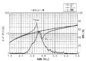
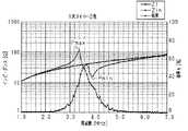
そして、負荷17として50Ωの抵抗を接続して、入力電圧として10Vpp(振幅5V)の正弦波1MHz〜7MHzを1次コイル13に供給して、1次コイル13のインピーダンス及び共鳴系12の入力インピーダンス並びに電力伝送効率ηを測定した。また、1次コイル13のインピーダンスの影響を調べるため、1次コイル13以外のコイルの仕様は変更せずに、1次コイル13の巻数を1巻及び4巻に変更した共鳴系12に対しても同じ条件で同じ測定を行った。測定結果を、横軸が周波数、縦軸がインピーダンス又は電力伝送効率ηを表すグラフにしたものを図2、図3及び図4に示す。図2〜図4では電力伝送効率ηを単に効率ηとして示している。なお、電力伝送効率ηは負荷での消費電力の1次コイルへの入力電力に対する割合を表し、%で示す場合は、次のようにして求められる。
Then, a 50 Ω resistor is connected as the
電力伝送効率η=(負荷での消費電力/1次コイルへの入力電力)×100[%]
図2〜図4の結果から次のことが言える。
1.1次コイル13のインピーダンスZ1は、巻数に拘わらず周波数が1MHzから7MHzまで増加するに伴って単調増加し、増加率は周波数の低い方が大きいことを確認することができる。Power transmission efficiency η = (power consumption at load / input power to primary coil) × 100 [%]
The following can be said from the results of FIGS.
1. The impedance Z1 of the
2.共鳴系12の入力インピーダンスZinは、2MHz以下及び6MHz以上では1次コイル13のインピーダンスとほぼ一致するように変化し、共鳴周波数付近においては並列共振、直列共振が順に生じて、極大点Pmax及び極小点Pminが生じるように変化する。 2. The input impedance Zin of the
3.電力伝送効率ηは、1次コイル13の巻数に拘わらずほぼ同じ周波数で最大になる。ここで、電力伝送効率ηが最大になる周波数をその共鳴系12における共鳴周波数と定義する。 3. The power transmission efficiency η is maximized at substantially the same frequency regardless of the number of turns of the
4.共鳴系12の入力インピーダンスZinの極大点Pmax及び極小点Pminが生じる周波数の値は1次コイル13の巻数に拘わらずほぼ一定になる。
5.共鳴系12の入力インピーダンスZinが極大点Pmaxとなる周波数と極小点Pminとなる周波数の間の周波数で、電力伝送効率ηが高くなる。特に、この周波数範囲内であって、共鳴系12の入力インピーダンスZinと1次コイル13のインピーダンスZ1とが等しくなる周波数付近で電力伝送効率ηが最大となる。4). The frequency value at which the maximum point Pmax and the minimum point Pmin of the input impedance Zin of the
5. The power transmission efficiency η increases at a frequency between the frequency at which the input impedance Zin of the
6.共鳴系12の入力インピーダンスZinが周波数の増加に伴い減少する周波数の範囲内で、電力伝送効率が高くなる。特に、この周波数範囲内であって、共鳴系の入力インピーダンスZinと1次コイル13のインピーダンスZ1とが等しくなる周波数付近で電力伝送効率ηが最大となる。 6). The power transmission efficiency becomes high within the frequency range where the input impedance Zin of the
この実施形態によれば、以下に示す効果を得ることができる。
(1)非接触電力伝送装置10は、交流電源11から交流電圧を印加される1次コイル13と、1次側共鳴コイル14と、2次側共鳴コイル15と、負荷17が接続される2次コイル16とを有する共鳴系12を備えている。そして、交流電源11の出力インピーダンスと共鳴系12の入力インピーダンスZinとが整合されている。したがって、交流電源11から効率良く電力を共鳴系12に供給することができる。また、共鳴系12の入力インピーダンスZinと交流電源11の出力インピーダンスとを整合させる際に、共鳴系12の入力インピーダンスZinに代えて1次コイル13のインピーダンスZ1のみを測定すればよい。したがって、容易に両インピーダンスを整合させることができる。According to this embodiment, the following effects can be obtained.
(1) The non-contact
(2)交流電源11は、共鳴系12における入力インピーダンスZinが極大点Pmaxとなる周波数と極小点Pminとなる周波数との間の周波数の交流電圧を1次コイル13に印加する。したがって、共鳴系12の電力伝送効率ηが高くなる。特に、このような周波数の範囲内であって、共鳴系12の入力インピーダンスZinと1次コイル13のインピーダンスZ1とが等しくなる周波数の交流電圧を1次コイルに印加した場合、共鳴系12の電力伝送効率ηは最大となる。 (2) The AC power supply 11 applies to the
(3)交流電源11は、共鳴系12における入力インピーダンスZinが周波数の増加に伴い減少する範囲内の周波数の交流電圧を1次コイル13に印加する。したがって、共鳴系12の電力伝送効率ηが高くなる。特に、このような周波数の範囲内であって、共鳴系12の入力インピーダンスZinと1次コイル13のインピーダンスZ1とが等しくなる周波数の交流電圧を1次コイル13に印加した場合、共鳴系12の電力伝送効率ηは最大となる。 (3) The AC power supply 11 applies an AC voltage having a frequency within a range in which the input impedance Zin in the
(4)1次コイル13のインピーダンスZ1を変更しても共鳴系12の共鳴周波数は変化しない。したがって、1次コイル13のインピーダンスZ1を調整するだけで、共鳴周波数を変化させずに、交流電源11の出力インピーダンスと共鳴系12の入力インピーダンスZinとを整合することができ、非接触電力伝送装置10の設計、調整が容易となる。 (4) Even if the impedance Z1 of the
(5)1次コイル13、1次側共鳴コイル14、2次側共鳴コイル15及び2次コイル16は同じ径に形成されている。したがって、1次コイル13及び1次側共鳴コイル14を一つの筒に巻くことで入力側の両コイルを容易に製作することができ、2次側共鳴コイル15及び2次コイル16を一つの筒に巻くことで出力側の両コイルを容易に製作することができる。 (5) The
(6)前記非接触電力伝送装置10の設計方法は、交流電源11から1次コイル13へ印加する交流電圧の周波数を設定した後、当該周波数で交流電源11の出力インピーダンスと共鳴系12の入力インピーダンスとが整合するように1次コイル13のインピーダンスを設定する。このとき、1次コイル13のインピーダンスを変えても共鳴系12の電力伝送特性には影響を及ぼさないので、整合後に再度共鳴系12や交流電源11の交流周波数等を調整する必要がない。したがって、交流電源11から効率良く共鳴系12に電力を供給できる非接触電力伝送装置10を提供できる。また、交流電源11の出力インピーダンスと共鳴系12の入力インピーダンスとの整合も容易になる。 (6) The design method of the non-contact
実施形態は前記に限定されるものではなく、例えば、次のように具体化してもよい。
○ 1次コイル13のインピーダンスZ1を調整する場合、1次コイル13の巻数を変更したり、径を変更したり、電線の太さを変更したり、電線の材質を変更したりすることで対応することができる。しかし、コイルの巻数及び径を変更するのが簡単である。The embodiment is not limited to the above, and may be embodied as follows, for example.
○ When adjusting the impedance Z1 of the
○ 電線を巻回してコイルを形成する場合、コイルは円筒状に限らない。例えば、三角筒状、四角筒状、六角筒状等の多角筒状や楕円筒状等の単純な形状の筒状としたり、対称図形ではなく他の異形断面の筒状としたりしてもよい。 ○ When a coil is formed by winding an electric wire, the coil is not limited to a cylindrical shape. For example, it may be a simple cylindrical shape such as a triangular cylindrical shape, a rectangular cylindrical shape, a hexagonal cylindrical shape, or an elliptical cylindrical shape, or a cylindrical shape other than a symmetrical figure. .
○ 1次側共鳴コイル14及び2次側共鳴コイル15は、電線が筒状に巻回されたコイルに限らず、例えば、図5に示すように、電線が一平面上で周回するように巻回された形状としてもよい。 The
○ コイルは、電線が密巻されて隣接する巻回部が接触する構成でも、巻回部が接触しないように巻回部の間隔を空けて電線が巻回された構成であってもよい。
○ 1次コイル13、1次側共鳴コイル14、2次側共鳴コイル15及び2次コイル16が全て同じ径に形成されている必要はない。例えば、1次側共鳴コイル14及び2次側共鳴コイル15は同じ径で、1次コイル13及び2次コイル16は異なる径としてもよい。The coil may have a configuration in which an electric wire is tightly wound and an adjacent winding portion comes into contact, or a configuration in which an electric wire is wound with a space between winding portions so that the winding portion does not come into contact.
The
○ 非接触電力伝送装置10の設計方法は、共鳴系12を構成する1次側共鳴コイル14及び2次側共鳴コイル15の仕様を設定した後、交流電源11の仕様を設定し、その交流電源11の出力インピーダンスと共鳴系12の入力インピーダンスが整合するように1次コイル13のインピーダンスを設定する方法に限らない。例えば、先ず、交流電源11の仕様を設定し、その仕様に合わせて共鳴系12を構成する1次側共鳴コイル14及び2次側共鳴コイル15の仕様及び1次コイル13のインピーダンスを設定してもよい。交流電源11の仕様を共鳴系12の仕様より先に設定するということは、共鳴系12の仕様を設定する際に、共鳴周波数が決められた状態で1次側共鳴コイル14及び2次側共鳴コイル15を構成する電線の材質、電線の太さ、コイルの径、巻数、両共鳴コイル間距離等の値を設定することになる。 The design method of the non-contact
Pmax…極大点、Pmin…極小点、10…非接触電力伝送装置、11…交流電源、12…共鳴系、13…1次コイル、14…1次側共鳴コイル、15…2次側共鳴コイル、16…2次コイル、17…負荷。 Pmax ... maximum point, Pmin ... minimum point, 10 ... non-contact power transmission device, 11 ... AC power supply, 12 ... resonance system, 13 ... primary coil, 14 ... primary resonance coil, 15 ... secondary resonance coil, 16 ... secondary coil, 17 ... load.
Claims (4)
Translated fromJapanese前記1次コイルのインピーダンスが、前記交流電源の出力インピーダンスと前記共鳴系の入力インピーダンスとが整合するように設定されており、
前記交流電源は、前記共鳴系の入力インピーダンスと周波数との関係をグラフにした場合の極大点と極小点との間に存在するインピーダンスに対応する周波数の交流電圧を前記1次コイルに印加することを特徴とする非接触電力伝送装置。A non-contact power transmission device including a resonance system having a primary coil to which an AC voltage is applied from an AC power source, a primary side resonance coil, a secondary side resonance coil, and a secondary coil to which a load is connected. And
The impedance of the primary coil is set so that the output impedance of the AC power supply matches the input impedance of the resonance system,
The AC power supply applies to the primary coil an AC voltage having a frequency corresponding to an impedance existing between a maximum point and a minimum point when the relationship between the input impedance and the frequency of the resonance system is graphed. A non-contact power transmission device characterized by the above.
前記1次コイルのインピーダンスが、前記交流電源の出力インピーダンスと前記共鳴系の入力インピーダンスとが整合するように設定されており、
前記交流電源は、前記共鳴系の入力インピーダンスが周波数の増加に伴い減少する範囲内の周波数の交流電圧を前記1次コイルに印加することを特徴とする非接触電力伝送装置。A non-contact power transmission device including a resonance system having a primary coil to which an AC voltage is applied from an AC power source, a primary side resonance coil, a secondary side resonance coil, and a secondary coil to which a load is connected. And
The impedance of the primary coil is set so that the output impedance of the AC power supply matches the input impedance of the resonance system,
The AC power supply, non-contact power transmissionapparatus characterized by applying an alternating voltage of a frequency in the range where the input impedance of the resonant system is decreased with increasing frequency to the primary coil.
前記交流電源から前記1次コイルに印加する交流電圧の周波数を設定した後、当該周波数で前記交流電源の出力インピーダンスと前記共鳴系の入力インピーダンスとが整合するように前記1次コイルのインピーダンスを設定し、
前記交流電源から前記1次コイルに印加する交流電圧の周波数として、前記共鳴系の入力インピーダンスと周波数との関係を調べて入力インピーダンスと周波数との関係をグラフにした場合の極大点と極小点との間の周波数を採用することを特徴とする非接触電力伝送装置の設計方法。Design of a contactless power transmission device including a resonance system having a primary coil to which an AC voltage is applied from an AC power source, a primary resonance coil, a secondary resonance coil, and a secondary coil to which a load is connected A method,
After setting the frequency of the AC voltage applied from the AC power source to the primary coil, the impedance of the primary coil is set so that the output impedance of the AC power source matches the input impedance of the resonance system at the frequency.And
As the frequency of the AC voltage applied from the AC power source to the primary coil, the relationship between the input impedance and the frequency of the resonance system and the relationship between the input impedance and the frequency are graphed. The design method of the non-contact electric power transmission apparatus characterizedby employ | adopting the frequency between .
前記交流電源から前記1次コイルに印加する交流電圧の周波数を設定した後、当該周波数で前記交流電源の出力インピーダンスと前記共鳴系の入力インピーダンスとが整合するように前記1次コイルのインピーダンスを設定し、
前記交流電源から前記1次コイルに印加する交流電圧の周波数として、前記共鳴系の入力インピーダンスが周波数の増加に伴い減少する範囲内の周波数を採用することを特徴とする非接触電力伝送装置の設計方法。Design of a contactless power transmission device including a resonance system having a primary coil to which an AC voltage is applied from an AC power source, a primary resonance coil, a secondary resonance coil, and a secondary coil to which a load is connected A method,
After setting the frequency of the AC voltage applied from the AC power source to the primary coil, the impedance of the primary coil is set so that the output impedance of the AC power source matches the input impedance of the resonance system at the frequency. And
A design ofa non-contact power transmission device, wherein a frequency within a range in which the input impedance of the resonance system decreases with an increase in frequency is adopted as the frequency of the AC voltage applied from the AC power source to the primary coil. Method.
Priority Applications (2)
| Application Number | Priority Date | Filing Date | Title |
|---|---|---|---|
| JP2008283563AJP5375032B2 (en) | 2008-11-04 | 2008-11-04 | Non-contact power transmission device and design method of non-contact power transmission device |
| US12/611,508US8432066B2 (en) | 2008-11-04 | 2009-11-03 | Non-contact power transmission apparatus and method for designing non-contact power transmission apparatus |
Applications Claiming Priority (1)
| Application Number | Priority Date | Filing Date | Title |
|---|---|---|---|
| JP2008283563AJP5375032B2 (en) | 2008-11-04 | 2008-11-04 | Non-contact power transmission device and design method of non-contact power transmission device |
Publications (2)
| Publication Number | Publication Date |
|---|---|
| JP2010114965A JP2010114965A (en) | 2010-05-20 |
| JP5375032B2true JP5375032B2 (en) | 2013-12-25 |
Family
ID=42133029
Family Applications (1)
| Application Number | Title | Priority Date | Filing Date |
|---|---|---|---|
| JP2008283563AExpired - Fee RelatedJP5375032B2 (en) | 2008-11-04 | 2008-11-04 | Non-contact power transmission device and design method of non-contact power transmission device |
Country Status (2)
| Country | Link |
|---|---|
| US (1) | US8432066B2 (en) |
| JP (1) | JP5375032B2 (en) |
Families Citing this family (122)
| Publication number | Priority date | Publication date | Assignee | Title |
|---|---|---|---|---|
| US7825543B2 (en) | 2005-07-12 | 2010-11-02 | Massachusetts Institute Of Technology | Wireless energy transfer |
| US9421388B2 (en) | 2007-06-01 | 2016-08-23 | Witricity Corporation | Power generation for implantable devices |
| US8115448B2 (en) | 2007-06-01 | 2012-02-14 | Michael Sasha John | Systems and methods for wireless power |
| CN102099958B (en)* | 2008-05-14 | 2013-12-25 | 麻省理工学院 | Wireless power transfer including interference enhancement |
| US8912687B2 (en) | 2008-09-27 | 2014-12-16 | Witricity Corporation | Secure wireless energy transfer for vehicle applications |
| US8901779B2 (en) | 2008-09-27 | 2014-12-02 | Witricity Corporation | Wireless energy transfer with resonator arrays for medical applications |
| US8466583B2 (en) | 2008-09-27 | 2013-06-18 | Witricity Corporation | Tunable wireless energy transfer for outdoor lighting applications |
| US8587153B2 (en) | 2008-09-27 | 2013-11-19 | Witricity Corporation | Wireless energy transfer using high Q resonators for lighting applications |
| US8461720B2 (en)* | 2008-09-27 | 2013-06-11 | Witricity Corporation | Wireless energy transfer using conducting surfaces to shape fields and reduce loss |
| US8692412B2 (en) | 2008-09-27 | 2014-04-08 | Witricity Corporation | Temperature compensation in a wireless transfer system |
| US9544683B2 (en) | 2008-09-27 | 2017-01-10 | Witricity Corporation | Wirelessly powered audio devices |
| US9106203B2 (en) | 2008-09-27 | 2015-08-11 | Witricity Corporation | Secure wireless energy transfer in medical applications |
| US9093853B2 (en) | 2008-09-27 | 2015-07-28 | Witricity Corporation | Flexible resonator attachment |
| US8686598B2 (en) | 2008-09-27 | 2014-04-01 | Witricity Corporation | Wireless energy transfer for supplying power and heat to a device |
| US9184595B2 (en) | 2008-09-27 | 2015-11-10 | Witricity Corporation | Wireless energy transfer in lossy environments |
| US8922066B2 (en) | 2008-09-27 | 2014-12-30 | Witricity Corporation | Wireless energy transfer with multi resonator arrays for vehicle applications |
| US8497601B2 (en) | 2008-09-27 | 2013-07-30 | Witricity Corporation | Wireless energy transfer converters |
| US8569914B2 (en) | 2008-09-27 | 2013-10-29 | Witricity Corporation | Wireless energy transfer using object positioning for improved k |
| US8410636B2 (en) | 2008-09-27 | 2013-04-02 | Witricity Corporation | Low AC resistance conductor designs |
| US8957549B2 (en) | 2008-09-27 | 2015-02-17 | Witricity Corporation | Tunable wireless energy transfer for in-vehicle applications |
| US9744858B2 (en) | 2008-09-27 | 2017-08-29 | Witricity Corporation | System for wireless energy distribution in a vehicle |
| US8552592B2 (en)* | 2008-09-27 | 2013-10-08 | Witricity Corporation | Wireless energy transfer with feedback control for lighting applications |
| US9105959B2 (en) | 2008-09-27 | 2015-08-11 | Witricity Corporation | Resonator enclosure |
| US8772973B2 (en) | 2008-09-27 | 2014-07-08 | Witricity Corporation | Integrated resonator-shield structures |
| US8643326B2 (en) | 2008-09-27 | 2014-02-04 | Witricity Corporation | Tunable wireless energy transfer systems |
| US9318922B2 (en) | 2008-09-27 | 2016-04-19 | Witricity Corporation | Mechanically removable wireless power vehicle seat assembly |
| US8324759B2 (en)* | 2008-09-27 | 2012-12-04 | Witricity Corporation | Wireless energy transfer using magnetic materials to shape field and reduce loss |
| US8947186B2 (en) | 2008-09-27 | 2015-02-03 | Witricity Corporation | Wireless energy transfer resonator thermal management |
| US8937408B2 (en) | 2008-09-27 | 2015-01-20 | Witricity Corporation | Wireless energy transfer for medical applications |
| US8304935B2 (en)* | 2008-09-27 | 2012-11-06 | Witricity Corporation | Wireless energy transfer using field shaping to reduce loss |
| US8629578B2 (en) | 2008-09-27 | 2014-01-14 | Witricity Corporation | Wireless energy transfer systems |
| US8461722B2 (en) | 2008-09-27 | 2013-06-11 | Witricity Corporation | Wireless energy transfer using conducting surfaces to shape field and improve K |
| US9515494B2 (en) | 2008-09-27 | 2016-12-06 | Witricity Corporation | Wireless power system including impedance matching network |
| US8723366B2 (en) | 2008-09-27 | 2014-05-13 | Witricity Corporation | Wireless energy transfer resonator enclosures |
| US8598743B2 (en) | 2008-09-27 | 2013-12-03 | Witricity Corporation | Resonator arrays for wireless energy transfer |
| US9601266B2 (en) | 2008-09-27 | 2017-03-21 | Witricity Corporation | Multiple connected resonators with a single electronic circuit |
| US8400017B2 (en) | 2008-09-27 | 2013-03-19 | Witricity Corporation | Wireless energy transfer for computer peripheral applications |
| US8901778B2 (en) | 2008-09-27 | 2014-12-02 | Witricity Corporation | Wireless energy transfer with variable size resonators for implanted medical devices |
| US9601261B2 (en) | 2008-09-27 | 2017-03-21 | Witricity Corporation | Wireless energy transfer using repeater resonators |
| US8471410B2 (en) | 2008-09-27 | 2013-06-25 | Witricity Corporation | Wireless energy transfer over distance using field shaping to improve the coupling factor |
| EP3179640A1 (en)* | 2008-09-27 | 2017-06-14 | WiTricity Corporation | Wireless energy transfer systems |
| US9065423B2 (en) | 2008-09-27 | 2015-06-23 | Witricity Corporation | Wireless energy distribution system |
| US8907531B2 (en) | 2008-09-27 | 2014-12-09 | Witricity Corporation | Wireless energy transfer with variable size resonators for medical applications |
| US8692410B2 (en)* | 2008-09-27 | 2014-04-08 | Witricity Corporation | Wireless energy transfer with frequency hopping |
| US8928276B2 (en) | 2008-09-27 | 2015-01-06 | Witricity Corporation | Integrated repeaters for cell phone applications |
| US9160203B2 (en) | 2008-09-27 | 2015-10-13 | Witricity Corporation | Wireless powered television |
| US20100259110A1 (en)* | 2008-09-27 | 2010-10-14 | Kurs Andre B | Resonator optimizations for wireless energy transfer |
| US8461721B2 (en) | 2008-09-27 | 2013-06-11 | Witricity Corporation | Wireless energy transfer using object positioning for low loss |
| US8946938B2 (en) | 2008-09-27 | 2015-02-03 | Witricity Corporation | Safety systems for wireless energy transfer in vehicle applications |
| US8482158B2 (en) | 2008-09-27 | 2013-07-09 | Witricity Corporation | Wireless energy transfer using variable size resonators and system monitoring |
| US9396867B2 (en) | 2008-09-27 | 2016-07-19 | Witricity Corporation | Integrated resonator-shield structures |
| US9601270B2 (en) | 2008-09-27 | 2017-03-21 | Witricity Corporation | Low AC resistance conductor designs |
| US8441154B2 (en) | 2008-09-27 | 2013-05-14 | Witricity Corporation | Multi-resonator wireless energy transfer for exterior lighting |
| US8587155B2 (en)* | 2008-09-27 | 2013-11-19 | Witricity Corporation | Wireless energy transfer using repeater resonators |
| US8487480B1 (en) | 2008-09-27 | 2013-07-16 | Witricity Corporation | Wireless energy transfer resonator kit |
| US9577436B2 (en) | 2008-09-27 | 2017-02-21 | Witricity Corporation | Wireless energy transfer for implantable devices |
| US9035499B2 (en) | 2008-09-27 | 2015-05-19 | Witricity Corporation | Wireless energy transfer for photovoltaic panels |
| US8669676B2 (en) | 2008-09-27 | 2014-03-11 | Witricity Corporation | Wireless energy transfer across variable distances using field shaping with magnetic materials to improve the coupling factor |
| US9246336B2 (en) | 2008-09-27 | 2016-01-26 | Witricity Corporation | Resonator optimizations for wireless energy transfer |
| US8933594B2 (en) | 2008-09-27 | 2015-01-13 | Witricity Corporation | Wireless energy transfer for vehicles |
| US8963488B2 (en) | 2008-09-27 | 2015-02-24 | Witricity Corporation | Position insensitive wireless charging |
| US8476788B2 (en) | 2008-09-27 | 2013-07-02 | Witricity Corporation | Wireless energy transfer with high-Q resonators using field shaping to improve K |
| US8362651B2 (en)* | 2008-10-01 | 2013-01-29 | Massachusetts Institute Of Technology | Efficient near-field wireless energy transfer using adiabatic system variations |
| DE102009006970A1 (en)* | 2009-02-02 | 2010-08-05 | Siemens Aktiengesellschaft | Potential-separated functional test for components |
| JP5625263B2 (en)* | 2009-05-18 | 2014-11-19 | トヨタ自動車株式会社 | Coil unit, non-contact power transmission device, non-contact power supply system, and electric vehicle |
| JP2011142559A (en)* | 2010-01-08 | 2011-07-21 | Sony Corp | Power feeding device, power receiving device, and wireless feeding system |
| JP5146488B2 (en)* | 2010-05-26 | 2013-02-20 | トヨタ自動車株式会社 | Power feeding system and vehicle |
| JP5177187B2 (en) | 2010-08-10 | 2013-04-03 | 株式会社村田製作所 | Power transmission system |
| US9602168B2 (en) | 2010-08-31 | 2017-03-21 | Witricity Corporation | Communication in wireless energy transfer systems |
| JP5126324B2 (en)* | 2010-09-10 | 2013-01-23 | トヨタ自動車株式会社 | Power supply apparatus and control method of power supply system |
| DE102011050342A1 (en)* | 2011-05-13 | 2012-11-15 | Dr. Hahn Gmbh & Co. Kg | Method and device for contactless transmission of electrical energy between a wall and a wing attached to this wall |
| RU2538762C1 (en)* | 2010-11-12 | 2015-01-10 | Ниссан Мотор Ко., Лтд. | Device of non-contact power supply |
| JP5648694B2 (en)* | 2010-12-24 | 2015-01-07 | トヨタ自動車株式会社 | Non-contact power supply system and power supply equipment |
| JP2012143117A (en)* | 2011-01-06 | 2012-07-26 | Toyota Industries Corp | Non-contact power transmission device |
| CN103443883B (en)* | 2011-01-14 | 2016-10-12 | 香港城市大学 | Apparatus and method for wireless power transfer |
| CN103370849B (en)* | 2011-02-15 | 2017-03-22 | 丰田自动车株式会社 | Non-contact power receiving apparatus, vehicle having the non-contact power receiving apparatus mounted therein, non-contact power supply equipment, method for controlling non-contact power receiving apparatus, and method for controlling non-contact |
| US9027236B2 (en)* | 2011-05-31 | 2015-05-12 | General Electric Company | Resonator structures and method of making |
| JP5590237B2 (en)* | 2011-06-13 | 2014-09-17 | 株式会社村田製作所 | Power transmission system and power receiving device |
| NZ593764A (en)* | 2011-06-27 | 2013-12-20 | Auckland Uniservices Ltd | Load control for bi-directional inductive power transfer systems |
| US9893566B2 (en) | 2011-06-30 | 2018-02-13 | Yazaki Corporation | Power supply system |
| EP2728711A1 (en)* | 2011-06-30 | 2014-05-07 | Yazaki Corporation | Power feeding system design method and power feeding system |
| WO2013002241A1 (en)* | 2011-06-30 | 2013-01-03 | 矢崎総業株式会社 | Electrical supply system |
| US9948145B2 (en) | 2011-07-08 | 2018-04-17 | Witricity Corporation | Wireless power transfer for a seat-vest-helmet system |
| CN108110907B (en) | 2011-08-04 | 2022-08-02 | 韦特里西提公司 | Tunable wireless power supply architecture |
| EP2754222B1 (en) | 2011-09-09 | 2015-11-18 | Witricity Corporation | Foreign object detection in wireless energy transfer systems |
| US20130062966A1 (en) | 2011-09-12 | 2013-03-14 | Witricity Corporation | Reconfigurable control architectures and algorithms for electric vehicle wireless energy transfer systems |
| JP5927826B2 (en)* | 2011-09-28 | 2016-06-01 | 日産自動車株式会社 | Contactless power supply |
| JP5781882B2 (en)* | 2011-09-29 | 2015-09-24 | トヨタ自動車株式会社 | Power transmission device, vehicle, and power transmission system |
| US9318257B2 (en) | 2011-10-18 | 2016-04-19 | Witricity Corporation | Wireless energy transfer for packaging |
| CA2853824A1 (en) | 2011-11-04 | 2013-05-10 | Witricity Corporation | Wireless energy transfer modeling tool |
| JP2015508987A (en) | 2012-01-26 | 2015-03-23 | ワイトリシティ コーポレーションWitricity Corporation | Wireless energy transmission with reduced field |
| JP5405694B1 (en)* | 2012-03-30 | 2014-02-05 | パナソニック株式会社 | Power transmission device, electronic device and wireless power transmission system |
| US9343922B2 (en) | 2012-06-27 | 2016-05-17 | Witricity Corporation | Wireless energy transfer for rechargeable batteries |
| JP5867607B2 (en)* | 2012-07-30 | 2016-02-24 | 日産自動車株式会社 | Non-contact power feeding device |
| US9287607B2 (en) | 2012-07-31 | 2016-03-15 | Witricity Corporation | Resonator fine tuning |
| US9697951B2 (en)* | 2012-08-29 | 2017-07-04 | General Electric Company | Contactless power transfer system |
| US9595378B2 (en) | 2012-09-19 | 2017-03-14 | Witricity Corporation | Resonator enclosure |
| EP2909912B1 (en) | 2012-10-19 | 2022-08-10 | WiTricity Corporation | Foreign object detection in wireless energy transfer systems |
| US9842684B2 (en) | 2012-11-16 | 2017-12-12 | Witricity Corporation | Systems and methods for wireless power system with improved performance and/or ease of use |
| US9857821B2 (en) | 2013-08-14 | 2018-01-02 | Witricity Corporation | Wireless power transfer frequency adjustment |
| FR3010252B1 (en)* | 2013-08-30 | 2015-08-21 | Continental Automotive France | BI-MODE MAGNETIC COUPLING CHARGE DEVICE AND METHOD FOR MOTOR VEHICLE |
| US9780573B2 (en) | 2014-02-03 | 2017-10-03 | Witricity Corporation | Wirelessly charged battery system |
| US9952266B2 (en) | 2014-02-14 | 2018-04-24 | Witricity Corporation | Object detection for wireless energy transfer systems |
| US9892849B2 (en) | 2014-04-17 | 2018-02-13 | Witricity Corporation | Wireless power transfer systems with shield openings |
| US9842687B2 (en) | 2014-04-17 | 2017-12-12 | Witricity Corporation | Wireless power transfer systems with shaped magnetic components |
| US9837860B2 (en) | 2014-05-05 | 2017-12-05 | Witricity Corporation | Wireless power transmission systems for elevators |
| JP2017518018A (en) | 2014-05-07 | 2017-06-29 | ワイトリシティ コーポレーションWitricity Corporation | Foreign object detection in wireless energy transmission systems |
| US9954375B2 (en) | 2014-06-20 | 2018-04-24 | Witricity Corporation | Wireless power transfer systems for surfaces |
| US10574091B2 (en) | 2014-07-08 | 2020-02-25 | Witricity Corporation | Enclosures for high power wireless power transfer systems |
| CN107258046B (en) | 2014-07-08 | 2020-07-17 | 无线电力公司 | Resonator equalization in wireless power transfer systems |
| US9843217B2 (en) | 2015-01-05 | 2017-12-12 | Witricity Corporation | Wireless energy transfer for wearables |
| JP6512600B2 (en)* | 2015-04-13 | 2019-05-15 | 一般財団法人電力中央研究所 | Contactless power transmission circuit and contactless power supply system |
| US10224752B2 (en) | 2015-08-28 | 2019-03-05 | Qualcomm Incorporated | Method and apparatus for computer aided designing, tuning and matching of wireless power transfer systems |
| US10248899B2 (en) | 2015-10-06 | 2019-04-02 | Witricity Corporation | RFID tag and transponder detection in wireless energy transfer systems |
| US9929721B2 (en) | 2015-10-14 | 2018-03-27 | Witricity Corporation | Phase and amplitude detection in wireless energy transfer systems |
| WO2017070227A1 (en) | 2015-10-19 | 2017-04-27 | Witricity Corporation | Foreign object detection in wireless energy transfer systems |
| WO2017070009A1 (en) | 2015-10-22 | 2017-04-27 | Witricity Corporation | Dynamic tuning in wireless energy transfer systems |
| US10075019B2 (en) | 2015-11-20 | 2018-09-11 | Witricity Corporation | Voltage source isolation in wireless power transfer systems |
| WO2017136491A1 (en) | 2016-02-02 | 2017-08-10 | Witricity Corporation | Controlling wireless power transfer systems |
| CN114123540B (en) | 2016-02-08 | 2024-08-20 | 韦特里西提公司 | Variable capacitance device and high-power wireless energy transmission system |
| US11211820B2 (en)* | 2017-05-15 | 2021-12-28 | The Board Of Trustees Of The University Of Illinois | Wireless power transfer at chip scale |
| WO2019006376A1 (en) | 2017-06-29 | 2019-01-03 | Witricity Corporation | Protection and control of wireless power systems |
Family Cites Families (7)
| Publication number | Priority date | Publication date | Assignee | Title |
|---|---|---|---|---|
| CN101860089B (en) | 2005-07-12 | 2013-02-06 | 麻省理工学院 | wireless non-radiative energy transfer |
| US7825543B2 (en) | 2005-07-12 | 2010-11-02 | Massachusetts Institute Of Technology | Wireless energy transfer |
| JP2008125198A (en)* | 2006-11-09 | 2008-05-29 | Ishida Co Ltd | Non-contact feeder system |
| KR20110117732A (en) | 2007-03-27 | 2011-10-27 | 메사추세츠 인스티튜트 오브 테크놀로지 | Wireless energy transfer |
| US8610312B2 (en)* | 2007-09-17 | 2013-12-17 | Hideo Kikuchi | Induced power transmission circuit |
| JP4453741B2 (en) | 2007-10-25 | 2010-04-21 | トヨタ自動車株式会社 | Electric vehicle and vehicle power supply device |
| WO2010035321A1 (en)* | 2008-09-25 | 2010-04-01 | トヨタ自動車株式会社 | Power supply system and electric vehicle |
- 2008
- 2008-11-04JPJP2008283563Apatent/JP5375032B2/ennot_activeExpired - Fee Related
- 2009
- 2009-11-03USUS12/611,508patent/US8432066B2/ennot_activeExpired - Fee Related
Also Published As
| Publication number | Publication date |
|---|---|
| US8432066B2 (en) | 2013-04-30 |
| US20100115474A1 (en) | 2010-05-06 |
| JP2010114965A (en) | 2010-05-20 |
Similar Documents
| Publication | Publication Date | Title |
|---|---|---|
| JP5375032B2 (en) | Non-contact power transmission device and design method of non-contact power transmission device | |
| JP5114364B2 (en) | Non-contact power transmission device and design method thereof | |
| JP4759610B2 (en) | Non-contact power transmission device | |
| JP5114372B2 (en) | Power transmission method and non-contact power transmission apparatus in non-contact power transmission apparatus | |
| JP5114371B2 (en) | Non-contact power transmission device | |
| JP5515659B2 (en) | Non-contact power transmission device | |
| JP5730587B2 (en) | Magnetic resonance type non-contact power feeding device | |
| JP5262785B2 (en) | Non-contact power transmission device | |
| EP2475073A1 (en) | Non-contact power transmission apparatus and power transmission method therefor | |
| WO2010067763A1 (en) | Non-contact power transmission apparatus and power transmission method using a non-contact power transmission apparatus | |
| CA2675498C (en) | Power supply apparatus for a capacitive load | |
| WO2010090323A1 (en) | Non-contact power transmission device | |
| KR101369415B1 (en) | Transmitter used in wireless power transfer and wireless power transfer system having the same | |
| JP5612956B2 (en) | Non-contact power transmission device | |
| CN107294216A (en) | A kind of transformer station's energization from magnetic field device | |
| CN103795155A (en) | Constant magnetic field fractional-turn switch power transformation device | |
| JP2012043966A (en) | Non-contact power supply coil | |
| HK1235556A1 (en) | Power supply apparatus for a capacitive load |
Legal Events
| Date | Code | Title | Description |
|---|---|---|---|
| A621 | Written request for application examination | Free format text:JAPANESE INTERMEDIATE CODE: A621 Effective date:20110107 | |
| A977 | Report on retrieval | Free format text:JAPANESE INTERMEDIATE CODE: A971007 Effective date:20120903 | |
| A131 | Notification of reasons for refusal | Free format text:JAPANESE INTERMEDIATE CODE: A131 Effective date:20120911 | |
| A131 | Notification of reasons for refusal | Free format text:JAPANESE INTERMEDIATE CODE: A131 Effective date:20130618 | |
| A521 | Request for written amendment filed | Free format text:JAPANESE INTERMEDIATE CODE: A523 Effective date:20130812 | |
| TRDD | Decision of grant or rejection written | ||
| A01 | Written decision to grant a patent or to grant a registration (utility model) | Free format text:JAPANESE INTERMEDIATE CODE: A01 Effective date:20130827 | |
| A61 | First payment of annual fees (during grant procedure) | Free format text:JAPANESE INTERMEDIATE CODE: A61 Effective date:20130909 | |
| LAPS | Cancellation because of no payment of annual fees |