JP5372314B2 - An inflexible catheter that bends in-plane - Google Patents
An inflexible catheter that bends in-planeDownload PDFInfo
- Publication number
- JP5372314B2 JP5372314B2JP2006035418AJP2006035418AJP5372314B2JP 5372314 B2JP5372314 B2JP 5372314B2JP 2006035418 AJP2006035418 AJP 2006035418AJP 2006035418 AJP2006035418 AJP 2006035418AJP 5372314 B2JP5372314 B2JP 5372314B2
- Authority
- JP
- Japan
- Prior art keywords
- catheter
- tip portion
- flexible
- distal end
- cross
- Prior art date
- Legal status (The legal status is an assumption and is not a legal conclusion. Google has not performed a legal analysis and makes no representation as to the accuracy of the status listed.)
- Active
Links
Images


Classifications
- A—HUMAN NECESSITIES
- A61—MEDICAL OR VETERINARY SCIENCE; HYGIENE
- A61M—DEVICES FOR INTRODUCING MEDIA INTO, OR ONTO, THE BODY; DEVICES FOR TRANSDUCING BODY MEDIA OR FOR TAKING MEDIA FROM THE BODY; DEVICES FOR PRODUCING OR ENDING SLEEP OR STUPOR
- A61M25/00—Catheters; Hollow probes
- A61M25/01—Introducing, guiding, advancing, emplacing or holding catheters
- A61M25/0105—Steering means as part of the catheter or advancing means; Markers for positioning
- A61M25/0133—Tip steering devices
- A61M25/0144—Tip steering devices having flexible regions as a result of inner reinforcement means, e.g. struts or rods
- A—HUMAN NECESSITIES
- A61—MEDICAL OR VETERINARY SCIENCE; HYGIENE
- A61B—DIAGNOSIS; SURGERY; IDENTIFICATION
- A61B18/00—Surgical instruments, devices or methods for transferring non-mechanical forms of energy to or from the body
- A61B18/04—Surgical instruments, devices or methods for transferring non-mechanical forms of energy to or from the body by heating
- A61B18/12—Surgical instruments, devices or methods for transferring non-mechanical forms of energy to or from the body by heating by passing a current through the tissue to be heated, e.g. high-frequency current
- A61B18/14—Probes or electrodes therefor
- A61B18/1492—Probes or electrodes therefor having a flexible, catheter-like structure, e.g. for heart ablation
- A—HUMAN NECESSITIES
- A61—MEDICAL OR VETERINARY SCIENCE; HYGIENE
- A61B—DIAGNOSIS; SURGERY; IDENTIFICATION
- A61B17/00—Surgical instruments, devices or methods
- A61B17/00234—Surgical instruments, devices or methods for minimally invasive surgery
- A61B2017/00292—Surgical instruments, devices or methods for minimally invasive surgery mounted on or guided by flexible, e.g. catheter-like, means
- A61B2017/003—Steerable
- A—HUMAN NECESSITIES
- A61—MEDICAL OR VETERINARY SCIENCE; HYGIENE
- A61M—DEVICES FOR INTRODUCING MEDIA INTO, OR ONTO, THE BODY; DEVICES FOR TRANSDUCING BODY MEDIA OR FOR TAKING MEDIA FROM THE BODY; DEVICES FOR PRODUCING OR ENDING SLEEP OR STUPOR
- A61M25/00—Catheters; Hollow probes
- A61M25/01—Introducing, guiding, advancing, emplacing or holding catheters
- A61M25/0105—Steering means as part of the catheter or advancing means; Markers for positioning
- A61M25/0133—Tip steering devices
- A61M25/0147—Tip steering devices with movable mechanical means, e.g. pull wires
Landscapes
- Health & Medical Sciences (AREA)
- Life Sciences & Earth Sciences (AREA)
- Engineering & Computer Science (AREA)
- Veterinary Medicine (AREA)
- General Health & Medical Sciences (AREA)
- Surgery (AREA)
- Biomedical Technology (AREA)
- Heart & Thoracic Surgery (AREA)
- Public Health (AREA)
- Animal Behavior & Ethology (AREA)
- Physics & Mathematics (AREA)
- Otolaryngology (AREA)
- Biophysics (AREA)
- Cardiology (AREA)
- Pulmonology (AREA)
- Plasma & Fusion (AREA)
- Nuclear Medicine, Radiotherapy & Molecular Imaging (AREA)
- Hematology (AREA)
- Anesthesiology (AREA)
- Medical Informatics (AREA)
- Molecular Biology (AREA)
- Media Introduction/Drainage Providing Device (AREA)
- Surgical Instruments (AREA)
- Electrotherapy Devices (AREA)
- Materials For Medical Uses (AREA)
Abstract
Description
Translated fromJapanese〔発明の分野〕
本発明は、湾曲操作可能なカテーテルの改良に関し、特に、面内でたわむ二方向カテーテルに関するものである。(Field of the Invention)
The present invention relates to an improved catheter capable of bending operation, and more particularly to a bi-directional catheter that bends in-plane.
〔発明の背景〕
電極カテーテルは、長年にわたり医療業務で広く使われている。電極カテーテルは、心臓の電気活動を刺激し、マッピングすること、及び、電気活動が異常である場所を焼灼することに使われている。BACKGROUND OF THE INVENTION
Electrode catheters have been widely used in medical practice for many years. Electrode catheters are used to stimulate and map cardiac electrical activity and to cauterize where electrical activity is abnormal.
使用時には、電極カテーテルを大きな静脈や、たとえば大腿動脈のような大きな動脈に挿入し、問題となっている心室に誘導する。心臓内部では、カテーテル先端部の位置および向きを正確に調整できることが重要であり、また、このことがそのカテーテルの有用性を主に決める。 In use, the electrode catheter is inserted into a large vein or large artery such as the femoral artery and guided to the ventricle in question. Within the heart, it is important that the position and orientation of the catheter tip can be accurately adjusted, and this mainly determines the usefulness of the catheter.
操作可能な(すなわち、たわませることができる)カテーテルは、一般に公知である。例えば、米国特許第RE34,502号には、操作ハンドルを有するカテーテルが記載されている。この操作ハンドルは、遠位端にピストン室があるハウジングを備えている。ピストンがそのピストン室に配置されていて、縦方向に動くことができる。カテーテル本体の近位端は、このピストンに取り付けられている。プラーワイヤ(puller wire)がハウジングに取り付けられていて、ピストンを通って、かつ、カテーテル本体を通って延びている。プラーワイヤの遠位端は、カテーテルの先端部分内に固定されている。このような構成では、ピストンがハウジングに対して縦方向に動くと、カテーテルの先端部分がたわむ。 Manipulatable (ie, deflectable) catheters are generally known. For example, US Pat. No. RE34,502 describes a catheter having an operating handle. The operating handle comprises a housing with a piston chamber at the distal end. A piston is located in the piston chamber and can move longitudinally. The proximal end of the catheter body is attached to this piston. A puller wire is attached to the housing and extends through the piston and through the catheter body. The distal end of the puller wire is secured within the tip portion of the catheter. In such a configuration, the distal end portion of the catheter bends as the piston moves longitudinally relative to the housing.
多くの場合、二方向操作可能カテーテル、つまり、通常は逆方向である2つの方向にたわませることができるカテーテルが望まれている。例えば、米国特許第6,210,407号には、カテーテルを通って延びる2つのプラーワイヤを有する二方向操作可能カテーテルが開示されている。プラーワイヤの遠位端は、カテーテルの先端部分の両側に固定されている。適当な二方向操作ハンドルが設けられており、このハンドルにより、各プラーワイヤを縦方向に動かすことができ、これにより、カテーテルを2つの逆向きの方向にたわませることができる。 In many cases, a bi-directional steerable catheter is desired, that is, a catheter that can be deflected in two directions that are normally opposite. For example, US Pat. No. 6,210,407 discloses a bi-directionally steerable catheter having two puller wires extending through the catheter. The distal end of the puller wire is secured to both sides of the catheter tip. Appropriate two-way operating handles are provided which allow each puller wire to be moved longitudinally, thereby allowing the catheter to be deflected in two opposite directions.
カテーテルが一方向性であるか、二方向性であるかに関わらず、通常、先端部分をカテーテルの面内でたわませることができ、これにより、カテーテルを心臓の中でより正確に制御できることが好ましい。しかし、一般に先端部分が柔軟な材料から作られていることから、面外(off-plane)のたわみを制限することが、ときとして困難である。したがって、常にカテーテルの面内でたわむ先端部分を有するカテーテルに対するニーズがある。 Regardless of whether the catheter is unidirectional or bidirectional, the tip can usually bend in the plane of the catheter so that the catheter can be controlled more precisely in the heart. Is preferred. However, it is sometimes difficult to limit off-plane deflection because the tip is generally made of a flexible material. Therefore, there is a need for a catheter that has a tip portion that always bends in the plane of the catheter.
〔発明の概要〕
本発明は、先端部分を面内でたわませるためにたわみ構造体を有する改良型操作可能カテーテルに向けられたものである。たわみ構造体は、先端部分に沿って長手方向に延びるように細長くしてあり、第1の図心軸(centroidal axis)回りの断面二次モーメントがより小さく、第1の図心軸にほぼ直交する第2の図心軸回りの断面二次モーメントがより大きい断面を有している。このような場合、たわみ構造体が先端部分にバイアスをかけ、断面二次モーメントがより大きい第2の図心軸の方に延びている面内でたわませ、断面二次モーメントがより小さい第1の図心軸の方に延びる面内でのたわみを妨げる。[Summary of the Invention]
The present invention is directed to an improved steerable catheter having a flexure structure for deflecting the tip portion in-plane. The flexure structure is elongated to extend longitudinally along the tip, has a smaller cross-sectional momentabout the first centroidal axis, and is approximately perpendicular to the first centroid axis. The second moment of section about the secondcentroid axis has a larger section. In such a case, the flexible structure biases the tip portion and bends in the plane extending toward the secondcentroid with a larger sectional secondary moment, and the sectional moment is smaller. 1 to prevent deflection in a plane extending toward thecentroid axis .
たわみ構造体は、ほぼ直交し、断面二次モーメントが等しくない、2つの図心軸があることを条件として、どのような形状の断面であってもよい。このような場合、たわみ構造体が先端部分にバイアスをかけ、断面二次モーメントがより大きい図心軸に平行な面内でたわませ、断面二次モーメントがより小さい図心軸に平行な面内での湾曲を妨げる。The flexure structure may be any cross-section, provided that there are twocentroid axes that are approximately orthogonal and have equal cross-sectional secondary moments. In such a case, the flexure structure biases the tip, deflects in a plane parallel to thecentroid axis with a larger section moment, and a plane parallel to thecentroid axis with a smaller section moment. Hinder internal curvature.
ある実施形態では、たわみ構造体が1つのたわみ部材を備えており、このたわみ部材は、x軸に沿った幅がWで、y軸に沿った薄さがTであるほぼ長方形の断面を有し、x軸に沿った断面二次モーメントIxと、y軸に沿った断面二次モーメントIyとは、以下のように定義される:
ここで、W=nTであり、nの範囲は約2および20の間であり、好ましくは、約10および15の間であり、より好ましくは、nが約12である。したがって、たわみ構造体は、先端部分にバイアスをかけてy軸に平行な面内でたわませ、x軸に平行な面内のたわみを妨げる。In some embodiments, the flexure structure comprises a flexure member having a generally rectangular cross section with a width W along the x axis and a thickness T along the y axis. and, a second moment Ix along the x-axis, the moment of inertia of Iy along the y-axis, is defined as follows:
Where W = nT and the range of n is between about 2 and 20, preferably between about 10 and 15, and more preferably n is about 12. Therefore, the deflection structure biases the tip portion in a plane parallel to the y axis and prevents deflection in the plane parallel to the x axis.
他の実施形態では、たわみ構造体が複数のたわみ部材を備えている。各たわみ部材は、x軸に沿った有効または組み合わせ断面二次モーメントと、y軸に沿った有効または組み合わせ断面二次モーメントに寄与している。このたわみ構造体は、先端部分にバイアスをかけ、有効断面二次モーメントがより大きい図心軸に平行な面内でたわませ、有効断面二次モーメントがより小さい図心軸に平行な面内のたわみを妨げる。In another embodiment, the flexure structure comprises a plurality of flexure members. Each flexure member contributes to an effective or combined cross-sectional second moment along the x-axis and an effective or combined cross-sectional second moment along the y-axis. This flexible structure biases the tip and deflects in a plane parallel to thecentroid axis with a larger effective cross-section moment, and in a plane parallel to thecentroid axis with a smaller effective cross-section moment. Hinders the deflection.
詳細な実施形態では、面内でたわむカテーテルが、近位端、遠位端、および中を通って延びるルーメンを有するカテーテル本体と、そのカテーテル本体の遠位端にある先端部分とを備えている。先端部分は、柔軟なプラースチック製の管部を備えており、正反対に対置された一対のルーメンがこの管部を通って延びている。カテーテルには、さらにプラーワイヤが2つ設けられていて、これらのプラーワイヤは、カテーテル本体の近位端にある操作ハンドルを使って操作される。たわみ構造体は、第1の図心軸回りの断面二次モーメントがより小さく、第1の図心軸にほぼ直交する第2の図心軸回りの断面二次モーメントがより大きくなるように構成してあり、先端部分のたわみを、断面二次モーメントがより大きい第2の図心軸に平行な面内に偏らせ、断面二次モーメントがより小さい第1の図心軸に平行な面内のたわみを妨げるようにしている。In a detailed embodiment, an in-plane flexible catheter comprises a catheter body having a proximal end, a distal end, and a lumen extending therethrough, and a tip portion at the distal end of the catheter body. . The tip portion includes a flexible plastic tube, and a pair of diametrically opposed lumens extend through the tube. The catheter is further provided with two puller wires, which are manipulated using an operating handle at the proximal end of the catheter body. The flexure structure is configured such that the cross-sectional secondary momentabout the firstcentroid axis is smaller and the cross-sectional secondary moment about the secondcentroid axis substantially orthogonal to the firstcentroid axis is larger. The deflection of the tip portion is biased in a plane parallel to the secondcentroid axis having a larger sectional secondary moment, and in a plane parallel to the firstcentroid axis having a smaller sectional secondary moment. I try to prevent the deflection.
より詳細な実施形態では、面内でたわむカテーテルがたわみ構造体を有し、このたわみ構造体が、プラーワイヤの間に配置された細長いたわみ部材を1つ備えている。たわみ部材は、より厚い寸法と、より薄い寸法とがある断面を有し、先端部分にバイアスをかけ、より薄い寸法に平行な面内でたわませ、より厚い寸法に平行な面内でのたわみを妨げるようにしている。 In a more detailed embodiment, an in-plane flexible catheter has a flexible structure that includes a single elongated flexible member disposed between the puller wires. The flexure member has a cross section with a thicker dimension and a thinner dimension, biases the tip, deflects in a plane parallel to the thinner dimension, and in a plane parallel to the thicker dimension. It prevents the deflection.
別のより詳細な実施形態では、面内でたわむカテーテルがたわみ構造体を有し、このたわみ構造体が、複数の細長いたわみ部材を備えており、これら複数の細長いたわみ部材は、第1の図心軸回りの有効または組み合わせ断面二次モーメントがより小さく、第2の図心軸回りの有効または組み合わせ断面二次モーメントがより大きくなるように構成されている。たわみ部材は、いっしょになってカテーテルの先端部分にバイアスをかけ、第2の図心軸に平行な面内でたわませ、第1の図心軸に平行な面内でのたわみを妨げる。In another more detailed embodiment, a catheter that flexes in-plane has a flexure structure, the flexure structure comprising a plurality of elongate flexure members, wherein the plurality of elongate flexure members are defined in the firstview. The effective or combined cross-sectional secondary moment around thecentral axis is smaller, and the effective or combined cross-sectional secondary moment around the secondcentroid is configured to be larger. The flexure members together bias the tip of the catheter, deflect in a plane parallel to the secondcentroid , and prevent deflection in a plane parallel to the firstcentroid .
〔発明の詳細な説明〕
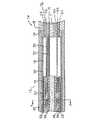
本発明のある実施形態では、二方向に操作可能な電極カテーテルが提供される。図1に示すように、カテーテル10は、近位端および遠位端を有する細長いカテーテル本体12と、カテーテル本体12の遠位端にある先端部分14と、カテーテル本体12の近位端にある操作ハンドル16とを有している。Detailed Description of the Invention
In one embodiment of the present invention, an electrode catheter operable in two directions is provided. As shown in FIG. 1, the
図2および図3に示されているように、カテーテル本体12は、軸上ルーメン、すなわち中央ルーメン18を1つだけ有する細長い管状の構造体を備えている。カテーテル本体12には可撓性があり、つまり、曲げることができるが、長手方向には実質的に圧縮することができない。カテーテル本体12は、適するどのような構造をしていてもよく、適するどのような材料から作ることもできる。現在のところ好ましい構造は、ポリウレタンまたはペバックス(PEBAX)から作られた外壁20を備えている。外壁20は、好ましくは、ステンレススチール等からなる編組メッシュが埋め込まれていて、カテーテル本体12のねじり剛性が高めてあり、これにより、操作ハンドル16を回転させたときに、先端部分14が対応して回転するようになっている。 As shown in FIGS. 2 and 3, the
カテーテル10の全長および径は、用途により変えることができる。現在のところ好ましいカテーテル10は、全長が約48インチ(122cm)である。カテーテル本体12の外径は重要ではないが、約8フレンチ(2.7mm)以下であることが好ましい。外壁20の内側の面は、補強チューブ22で裏張りがされていることが好ましい。補強チューブ22は、適するどのような材料でも作ることができ、好ましくは、ナイロンまたはポリイミド製である。補強チューブ22は、編組式外壁20とともに、曲げおよびねじりの安定性を改善し、同時に、カテーテル本体12の壁厚を最小にし、これにより、中央ルーメン18の直径を最大にする。補強チューブ22の外径は、外壁20の内径とほぼ等しいか、若干小さい。特に好ましいカテーテル10は、外径が約0.092インチ(2.34mm)であり、ルーメン18の直径が約0.052インチ(1.32mm)である。必要であれば、補強チューブを省くこともできる。 The overall length and diameter of the
先端部分14は、柔軟な管部19からなる短い部分を備えており、柔軟な管部19は、面内でたわませるために先端部分にバイアスをかけるたわみ構造体17を有している。図3aに図示したように、たわみ構造体は、y図心軸(centroidal axis)に沿って方向AおよびBに曲がり、x図心軸に沿った方向CおよびDへの曲げを妨げる、という性向を示す。たわみ構造体は、(例えば、z軸に沿って)細長くしてあり、より薄い寸法Tがy図心軸に沿って延び、より厚い寸法Wがx図心軸に沿って延びる断面21を有している。したがって、たわみ構造体は、以下の式で定義するように、x図心軸回りの断面二次モーメントIxがより小さく、y図心軸回りの断面二次モーメントIyがより大きい。
ここで、W=nTであり、nの範囲は約2から20の間であり、好ましくは約10から15の間であり、より好ましくは、nが約12である。このような場合、たわみ構造体17は、y図心軸に平行な方向または面(つまり、YZ面)内で曲がり、x図心軸に平行な方向または面(つまり、XZ面)内での曲げを妨げる傾向がある。このように、たわみ構造体は、「面内(in-plane)」での二方向にたわませる、つまり、断面二次モーメントがより大きい図心軸に平行、すなわち一直線にそろっている面内で二方向にたわませ、断面二次モーメントがより小さい図心軸に平行、すなわち一直線にそろっている面内での「面外(off-plane)」二方向たわみを妨げる。The
Here, W = nT and the range of n is between about 2 and 20, preferably between about 10 and 15, and more preferably n is about 12. In such a case, the
図示の実施形態では、細長いたわみ構造体17がほぼ長方形の断面を有し、大きい方の表面領域がXZ面内に広がっていて、一方、小さい方の表面領域がYZ面内に広がっている。したがって、構造体17のこの実施形態における面内たわみは、たわみ構造体の大きい方の表面領域(つまり、図3aのXZ面)に対してほぼ直交する面(つまり、図3aのYZ面)におけるたわみとも説明できる。 In the illustrated embodiment, the
当業者にとっては当然のことであるが、断面が長方形である必要はなく、楕円形にしてもよく、より正確に言えば、より厚い有効または組み合わせ寸法と、より薄い有効または組み合わせ寸法とがあり、このために2つの図心軸回りの断面二次モーメントが等しくなく、特に、一方の図心軸回りの有効または組み合わせ断面二次モーメントが、その第1の図心軸に対してほぼ直交する他の図心軸回りの有効または組み合わせ断面二次モーメントよりも小さい限り、どのような形状であってもよい。It will be appreciated by those skilled in the art that the cross-section need not be rectangular, but may be oval, more precisely, there are thicker effective or combined dimensions and thinner effective or combined dimensions. for this reason the unequal twoZukokorojiku around the second moment, in particular, effective or combined moment of inertia of the oneZukokorojiku around is substantially perpendicular to the firstZukokorojiku Any shape may be used as long as it is smaller than the effective or combined sectional moment of inertiaabout the othercentroid axis .
図4,5及び6に図示した実施形態では、たわみ構造体17が平坦帯状体を備えており、この平坦帯状体は、管部19の曲げ中立軸、すなわち中心線15に沿って長手方向に延び、最大平坦安定性(maximum planar stability)を高めている。帯状体は、形状記憶および/または超弾性特性による可撓性がある金属、プラースチック、セラミックまたはガラスから作られた細長いフラットワイヤ、すなわちシート状ワイヤであることがある。好ましくは、この材料は、降伏する前に非常に高い割合で歪む。たわみ構造体に適するいくつかの材料としては、ステンレススチール、ニチノール、および準安定相のチタンモリブデン合金(metastable titanium-molybdenum)をベースとする合金がある。好ましい実施形態では、帯状体が、長手方向にほぼ一様な長方形断面(図6)を有する。適するワイヤでは、Wが約0.070インチ(1.778mm)、Tが約0.005インチ(0.127mm)であり、nが約14であることがある。帯状体は、面内で曲がる、つまり、より薄い寸法に沿って曲がりやすく、より厚い寸法に沿った曲がりを妨げる傾向を自然と示す。 In the embodiment illustrated in FIGS. 4, 5 and 6, the
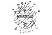
管部19には、複数の軸外(off-axis)ルーメンがあり、これらルーメンには、たわみ構造体17を挟んで互いに正反対に対置されたルーメン23および25が含まれる。各ルーメン23および25には、後述するように先端部分の向きを変えるためのプラーワイヤ(puller wire)32が通されている。管部には、先端部分14の電極用リードワイヤ30を通すために第3の軸外ルーメン26もある。ルーメンの正確なサイズは重要ではなく、ルーメンに通す部品のサイズに依存する。当業者には分かるように、さらに別の軸外ルーメンを必要に応じて設けることもできる。例えば、図6に示すように、先端部分の遠位端から出す流体を注入するために、チューブセグメント29を通すルーメン27を設けることもでき、および/または、先端部分に設けられた温度センサおよび/またはナビゲーションセンサなどのためのさらに別のワイヤおよびケーブルを通すためのルーメン28および31を設けることもできる。 The
柔軟な管部19は、当該技術分野で公知のように、プラースチック単一片を1つだけ備えていることもあるし、一組の層を備えていることもある。例えば、柔軟な管部19は、プラースチック製のコアと、コアを取り囲むプラースチック製の内層と、内層を取り囲むステンレススチール製の編組式メッシュと、編組式メッシュを取り囲むプラースチック製外層とを備えていることもある。コアは、たわみ構造体17およびマンドレルに被せるようにプラースチックを射出成形することで作ることが好ましい。マンドレルは、軸外ルーメンを形成するために、後で取り外す。当業者なら分かることであるが、射出成形によっても、および/または押し出し成形および型成形した一群の部品を融合させることによっても、たわみ構造体17を管部19に組み込むことができ、これにより、管部19およびたわみ構造体17がぴったりと接着、融合、成形、融解、および/または機械的に取り付けられ、管部19およびたわみ構造体17が概して、バイアス機能を内蔵した単一のユニットとして振る舞い、予め定められた仕方でたわむことができる。 The
コアの上には、任意の適当な手法、例えば押し出し成形などにより内層を形成する。このことは、コアの押し出し成形と同時に行うことができる。その後、編組式メッシュを内層の上に形成する。編組式メッシュは、編み込み螺旋部材を、通常は12、16、または24個備えており、その半分は、一方の方向に延びており、他の半分は反対方向に延びている。締まり具合、すなわち、カテーテルの軸に平行な線に対する螺旋部材の編組角度および螺旋部材と交差する角度は、重要ではないが、約45度であることが好ましい。螺旋部材は、高弾性係数を有する導電性材料から作られていることが好ましい。好ましい螺旋部材は、ステンレススチール製ワイヤから作られている。公知である、編組式メッシュを形成するための他の方法を使うこともできる。最後に、外層を編組式メッシュの上に、適当な任意の手法、好ましくは押し出し成形により形成する。 On the core, an inner layer is formed by any appropriate method such as extrusion. This can be done simultaneously with the extrusion of the core. Thereafter, a braided mesh is formed on the inner layer. Braided meshes typically have 12, 16, or 24 braided spiral members, half of which extend in one direction and the other half in the opposite direction. The degree of tightening, i.e., the braid angle of the helical member relative to a line parallel to the axis of the catheter and the angle intersecting the helical member is not critical, but is preferably about 45 degrees. The helical member is preferably made of a conductive material having a high elastic modulus. A preferred helical member is made of stainless steel wire. Other methods known in the art for forming braided meshes can also be used. Finally, the outer layer is formed on the braided mesh by any suitable technique, preferably extrusion.
当業者には分かるであろうが、先端部分14における層の具体的な数および構成は、重要ではない。例えば、内層は、特に比較的小さな径の先端部分が望まれている場合には、省くことができる。編組式メッシュも省くことができる。この場合、先端部分14は、オプションとして、プラースチック層を加えずに形成した単一コアを備えることがある。 As will be appreciated by those skilled in the art, the specific number and configuration of layers in the
先端部分14は、普通、カテーテル本体12よりも柔軟である。先端部分14の外径は、カテーテル本体12の外径と同様に、約8フレンチ(約2.7mm)以下であることが好ましく、より好ましくは約6.5フレンチ(約2.2mm)以下であるが、カテーテルを利用しようとする特定の用途により変わることがある。 The
カテーテル本体12を先端部分14に取り付けるための好ましい手段が図2に図示されている。先端部分14の近位端は、外周段部(outer circumferential notch)34を備えており、この外周段部34が、カテーテル本体12の外壁20の内側の面を受ける。先端部分14と、カテーテル本体12とは、接着剤などでくっつける。もっとも、先端部分14とカテーテル本体12とをくっつける前に、補強チューブ22をカテーテル本体12に挿入する。補強チューブ22の遠位端は、カテーテル本体12の遠位端近くに、ポリウレタン接着剤などを用いた接着接合部を形成することにより、動かないようにくっつける。好ましくは、カテーテル本体12の遠位端と、補強チューブ22の遠位端との間に、例えば約3mmの小さな間隔を設け、先端部分14の段部34を入れるための空間がカテーテル本体12にできるようにする。補強チューブ22の近位端に力を加え、補強チューブ22が圧縮されている間に、補強チューブ22および外壁20の間に、速乾性の接着剤、例えばスーパーグリューRTM(Super Glue.RTM)によって、第1の仮留用の接着剤接合部(不図示)を作る。その後、補強チューブ22および外壁20の近位端の間に、もっとゆっくりと乾くが、より恒久的である接着剤、例えばポリウレタンを使って第2の接着剤接合部を形成する。本発明によれば、カテーテル本体12および先端部分14をくっつけるための他の適当な手法もまた利用することができる。 A preferred means for attaching the
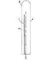
図4は、先端部分14の概略縦断面図である。先端部分14の遠位端は、先端電極38を保持している。先端部分14の長手方向に沿って3つのリング電極40が取り付けられている。各リング電極40の長さは重要でないが、約1mmから約3mmの範囲にあることが好ましい。リング電極40の間隔は、リング電極40のエッジが接触しない限り、重要ではない。必要であれば、リング電極40をより多く設けることも、より少なく設けることもできる。 FIG. 4 is a schematic longitudinal sectional view of the
先端電極38およびリング電極40は、それぞれ、別個の電極用リードワイヤ30に接続されている。リードワイヤ30は、先端部分14のルーメン26、カテーテル本体12の中央ルーメン18、および操作ハンドル16を通って延びている。各リードワイヤ30の近位端は、操作ハンドル16の近位端から延び出していて、適切なコネクターに接続されている。このコネクターは、適当なモニター、電源、その他に差し込む、または別の方法で接続することができる。 The
リードワイヤ30は、先端電極38およびリング電極40に、従来の任意の手法で接続されている。リードワイヤ30の先端電極38への接続は、図4に示すように、半田などで行うことが好ましい。リードワイヤ30のリング電極38への接続は、好ましくは、図4に示すように、最初に、先端部分14の壁部を通ってルーメン26に達し、リードワイヤが通る小さな孔を作ることにより行う。このような孔は、例えば、先端部分14の壁部に針を刺し通し、その針を十分に加熱して、恒久的な孔を形成することにより作ることができる。次にマイクロフックなどを使ってリードワイヤ30をその孔に引き通す。次に、リードワイヤ30の端部の全てのコーティングを剥がし、リング電極40の下面に溶接し、次に、リング電極40を孔をふさぐ位置へとスライドさせ、ポリウレタン接着剤などを使って所定位置に固定する。先端電極38のリードワイヤの遠位端は、先端電極38の止まり穴37に入れる。この遠位端は、止まり穴の中で先端電極に半田付けするか、溶接する。 The
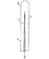
2つのプラーワイヤ32は、カテーテルを通って延びている。各プラーワイヤ32は、操作ハンドル16から延びて、カテーテル本体12の中央ルーメン18を通って、図5に示すように、先端部分14の、軸外ルーメン23および25の一方に入っている。より詳細に後述するように、各プラーワイヤ32の近位端は、操作ハンドル16内で固定されており、各プラーワイヤ32の遠位端は、先端部分14内で固定されている。 Two
各プラーワイヤ32は、ステンレススチールまたはニチノールなど、適する任意の材料から作る。各プラーワイヤ32は、テフロン(登録商標).RTM(Teflon.RTM)などからなるコーティングのようなの被覆がしてあることが好ましい。各プラーワイヤ32の直径は、好ましくは、約0.006インチ(0.152mm)から約0.0010インチ(0.0254mm)の範囲である。好ましくは、両プラーワイヤ32の直径が等しい。 Each
各プラーワイヤ32は、先端部分14の遠位端、またはその近くに固定されている。図5に描いた実施形態では、プラーワイヤ32が両方とも先端電極38の止まり穴37に溶接などで固定されている。あるいは、プラーワイヤ32の一方または両方を、2000年11月10日出願の米国特許出願第09/710,210号に記載のように、先端部分14の側壁に固定することもできる。米国特許出願第09/710,210号の全開示内容は、この言及により本明細書に組み込まれる。プラーワイヤ32を先端部分14に固定するための他の手段は、当業者には分かるであろうし、本発明の範囲内に含まれる。 Each
描いた実施形態では、プラーワイヤ32の遠位端が先端部分14の両側につけられている。このような構造により、先端部分14を両方向にたわませることができる(図3aおよび図6における矢印BおよびAを参照のこと)。 In the depicted embodiment, the distal end of the
カテーテルは、2つの圧縮コイル46をさらに備えている。各圧縮コイル46は、図2および図3に示すように、カテーテル本体12の中の対応するプラーワイヤ32を囲んでいる。各圧縮コイル46は、適する任意の金属、例えばステンレススチールなどから作られている。各圧縮コイル46は、柔軟であるが、つまり、曲がるが、圧縮しにくいように、それ自体にきつく巻かれている。各圧縮コイル46の内径は、それに対応づけられているプラーワイヤ32の直径よりもわずかに大きい。例えば、プラーワイヤ32の直径が約0.007インチ(約0.178mm)である場合、対応する圧縮コイル46は、内径が約0.008インチ(約0.203mm)であることが好ましい。プラーワイヤ32に施されているコーティングにより、プラーワイヤ32は、圧縮コイル46内を自由にスライドできる。中央ルーメン18の中で圧縮コイル46とリードワイヤ30とが接触しないように、各圧縮コイル46の外側の面が、ほぼ全長にわたって、柔軟な非導電性シース48で覆われている。壁部が薄いポリイミド製の管部から作られた非導電性シース48が現在のところ好ましい。 The catheter further includes two compression coils 46. Each
カテーテル本体12の遠位端またはその近くにおいて、2つの圧縮コイル46は、補強チューブ22の内部で正反対の位置に配置されており、これにより、先端部分14の、プラーワイヤ32が通されている2つの軸外ルーメン23および25に、2つの圧縮コイル46の位置を合わせることができる。圧縮コイル46および補強チューブ22は、圧縮コイル46が、補強チューブ22の中で、密に、かつ、スライド可能に詰め込まれる大きさになっている。このような構造により、リードワイヤ30が2つの圧縮コイル46のあたりに分布し、コイルの取り付け位置不良が起こらない。 At or near the distal end of the
圧縮コイル46は、カテーテル本体12内でポリウレタン接着などを用いて固定されている。各圧縮コイル46は、近位端において、カテーテル本体12内の補強チューブ22の近位端に接着剤接合部(不図示)によって固定されている。補強チューブ22を使用していない場合には、各圧縮コイルをカテーテル本体12の外壁20に直接固定する。 The
各圧縮コイル46の遠位端は、カテーテル本体12内の補強チューブ22の遠位端に接着剤接合部52によって固定されているか、補強チューブ22を使用していない場合には、カテーテル本体12の外壁20の遠位端に直接固定されている。あるいは、圧縮コイル46の遠位端は、先端部分14の、軸外ルーメン23および25の中へと延びていて、圧縮コイル46の遠位端において、先端部分14の近位端に接着剤接合部によって固定されていてもよい。描いた実施形態では、圧縮コイル46の各々が、シース48で覆われているので、シースが圧縮コイルに確実に接着されたことが保証されるように注意しなければならない。リードワイヤ30もまた、接着剤接合部に固定することができる。もっとも、必要であれば、プラースチック管部などの形態のトンネルを接着剤接合部においてリードワイヤの周りに設けることにより、リードワイヤを接着剤接合部でスライド可能にすることもできる。 The distal end of each
接着剤接合部は、ポリウレタン接着剤などを含むことが好ましい。接着剤は、注射器などを使って、カテーテル本体の外側表面20および中央ルーメン18の間に作られた穴を通して塗布してもよい。このような穴は、例えば、針などを外壁20および補強チューブ22に刺し、恒久的な穴が形成されるように十分に加熱することによって形成してもよい。次に接着剤がその穴を通して圧縮コイル46の外側の面まで入れられ、外周面の周りに毛管作用で広がり、各圧縮コイル46を囲んでいるシース48の周囲全体に接着剤接合部を形成する。接着剤が、コイルの端部を覆うように毛管作用で広がり、プラーワイヤがコイル内でスライドできなくなることにならないことが保証されるように気を付けなければならない。 The adhesive joint preferably includes a polyurethane adhesive or the like. The adhesive may be applied through a hole made between the
図5に示されるように、軸外ルーメン23および25の中では、各プラーワイヤ32が、好ましくはテフロン(登録商標)RTMで作られたプラースチック製シース42で取り囲まれている。このプラースチック製シース42により、先端部分14がたわんだときに、プラーワイヤ32が先端部分14の壁部に食い込むことが防止される。各シース42は、各プラーワイヤ32の遠位端近くで終端している。あるいは、各プラーワイヤ32が圧縮コイルで囲まれていることもある。この圧縮コイルは、カテーテル本体を通って延びている圧縮コイルに比べて、巻きが長手方向に伸びていて、このため、囲んでいるこの圧縮コイルは、曲げることも、圧縮することも可能である。 As shown in FIG. 5, within the off-
カテーテル本体12に対してプラーワイヤ32を長手方向に動かすと、先端部分14が、そのプラーワイヤを固定した先端部分の側面の方向へたわむが、このようなプラーワイヤ32の動きは、操作ハンドル16を適当に操作することにより行う。本発明での使用に適した二方向操作ハンドルは、2001年3月30日に出願され、発明の名称が「プーリー構造を有する操作ハンドルを備えた操作可能カテーテル」である米国特許出願第09/822,087号に記載されている。米国特許出願第09/822,087号の全開示内容は、この言及により本明細書に組み込まれる。適する他の二方向操作ハンドルは、米国特許第6,123,699号、第6,1,277号、第6,183,463号、および第6,198,974号に記載されており、これらの全開示内容は、この言及により本明細書に組み込まれる。 When the
図4および5の実施形態では、先端部分14の柔軟な管部19の遠位端に、先端電極の段部付き近位端の心棒部(stem)43が入っている。ポリウレタン製接着剤または他の接着剤を使って先端部分14および先端電極38の間の接触面を固定してもよい。先端部分14と先端電極38とをさらにしっかりと取り付けるために、先端電極の近位端に(図5に破線で示した)ポケット部47を形成して、たわみ構造体17の遠位端を入れることもできる。ポリウレタン製接着剤または他の接着剤を使って、たわみ構造体の遠位端をポケットに接着してもよい。 4 and 5, the distal end of the
図6の実施形態に示したように、プラーワイヤ32が通されているルーメン23および25は、たわみ構造体17の平面にほぼ垂直な直径に沿って、互いから約180度離れたところにある。このような場合、プラーワイヤは、たわみ構造体と協働しながら作用して、先端部分を面内でたわませる。このような配置により、先端部分がたわんでいるときのねじれが減り、都合がよい。 As shown in the embodiment of FIG. 6, the
たわみ構造体17は、先端部の横方向安定性を増大させるようにも作用し、これにより、ユーザは、心臓組織に接触させる力をより大きくすることができる。発明の構造により、心臓組織が先端部分14の近位部分に力を加えた場合、先端部分14の遠位部分がその心臓組織と反対の方へたわむことはなく、むしろ、帯状体17により、その心臓組織に向けて押し戻される。 The
図7aは、先端部分14の特に好ましい実施形態を図示している。管部19は、わずかに楕円形の断面を有し(例えば、2つの半楕円部を接合することで作られる)、寸法は約0.092インチ(約2.337mm)であり、直交する寸法が約0.087インチ(約2.210mm)である。たわみ構造体17は、幅が約0.072インチ(1.829mm)であり、薄さが約0.006インチ(約0.152mm)である。ほとんどの場合、たわみ構造体のより厚い寸法側を管部19のより厚い寸法側に合わせ、より薄い寸法側を管部19のより薄い寸法側に合わせ、これにより、管部19が、たわみ構造体の面内たわみバイアス(in-plane deflection bias)と協働するようにする。プラーワイヤ用ルーメン23および25は、より薄い寸法を挟んでたわみ部材17の反対側にあり、付加的なルーメン26,27,28および31は、正反対に対置した構成になるように2つずつ対になっている。 FIG. 7 a illustrates a particularly preferred embodiment of the
当業者には分かるように、たわみ構造体17の構成は、後述するように、図1から図6に示したものに限定されない。図7に示すように、付加的なルーメン26および27は、たわみ構造体17と同一の直径に沿って配置することができる。さらに、依然として面内たわみであるが、異なるたわみ方が必要であれば、例えば、遠くのプラーワイヤ32bよりも近くのプラーワイヤ32aで先端部分14をより簡単にたわませること(図8参照)が必要であれば、図8および図9に示すように、構造体17を中心線15から外れたところに配置することもできる。この場合、付加的なルーメン26および27は、適切に、または必要に応じて再配置される。 As will be appreciated by those skilled in the art, the configuration of the
構造体17の断面21の大きさは、構造体17の長手方向に一定でなくてもよい。図10および図11に示した実施形態では、たわみ構造体がその長手方向にテーパーが付けられている。つまり、構造体17の近位端におけるたわみ構造体の長方形断面が遠位端よりも大きい。さらに、先端部分14のたわみ特性をさらに変えるために、増大は断面の半分だけ、例えば、図10に示すように中心線15の上側だけであってもよいし、断面の全体、例えば、図11に示すように中心線15の上側および下側であってもよい。 The size of the
別の代替実施形態では、たわみ構造体17が複数の部材または部分17iを備えており、各部材17iが、長方形、正方形、または円形断面を有している。図12から図14に示すように、2つ以上のたわみ部材17iがあってもよく、これらのたわみ部材17iは、N行M列からなるN×M配列構造にほぼ配置されている。ここで、厚さ寸法に広がっているNの範囲は、1と3の間であり、幅寸法に広がっているMの範囲は、2と50の間である。 In another alternative embodiment, the
図12の実施形態では、2つのたわみ部材17iがあり、これらのたわみ部材17iは、N=1かつM=2のように1行2列に広がっており、各たわみ部材17iは、長方形断面(正方形断面が含まれることがある)を有する。図13の実施形態では、6つのたわみ部材17iがあり、これらのたわみ部材17iは、N=1かつM=6のように1行6列に広がっており、各たわみ部材17iは、(普通の針金を用いた場合のごとく)円形断面を有する。図14の実施形態では、10のたわみ部材17iがあり、これらのたわみ部材17iは、N=2かつM=5のように2行5列に広がっており、列は、互いに中心がずれている。 In the embodiment of FIG. 12, there are two flexible members 17i, which are spread in one row and two columns such that N = 1 and M = 2, and each flexible member 17i has a rectangular cross section ( Square cross section may be included). In the embodiment of FIG. 13, there are six flexible members 17i, which are spread in one row and six columns such that N = 1 and M = 6, and each flexible member 17i is It has a circular cross-section (as with a wire). In the embodiment of FIG. 14, there are ten flexible members 17i, which are spread in 2 rows and 5 columns, such as N = 2 and M = 5, and the columns are offset from each other. .
上述した変形例のいずれの場合も、有効または組み合わせ断面二次モーメントIxおよびIyが等しくない限り、先端部分は、面内でたわむように依然としてバイアスをかけられる。したがって、複数のたわみ部材を備えるたわみ構造体は、面内で曲がるという性向、つまり、たわみ構造体のより薄い寸法に平行で、断面二次モーメントがより大きい面内で曲がり、たわみ構造体のより厚い寸法に平行で、断面二次モーメントがより小さい面内での曲がりを妨げるという傾向を依然として自然と示すのである。また、これも当然のことながら、先端部分の湾曲特性をさらに変えるのに、各たわみ部材の近位端および遠位端を長手方向の同じ位置にする必要はない。In any of the variations described above, as long as the effective or combined cross-sectional second moments Ix and Iy are not equal, the tip portion is still biased to deflect in-plane. Therefore, a flexure structure comprising a plurality of flexure members tends to bend in-plane, i.e., bend in a plane parallel to the thinner dimension of the flexure structure and with a larger cross-sectional moment of inertia. It still naturally demonstrates the tendency to bend in a plane that is parallel to the thick dimension and has a smaller moment of inertia. Again, it should be understood that the proximal and distal ends of each flex member need not be in the same longitudinal position to further change the curvature characteristics of the tip portion.
別の実施形態では、プラーワイヤを通したルーメンが、図12から図13および図15に示すように、非円形の断面を有する。詳しくは、ルーメン23および25は、各々、半円形断面を有し、リードワイヤ30および/または注入管29のような他の部品を入れることができる。注目すべきことは、たわみ構造体17が管部19にしっかりと埋め込まれる限りは、ルーメンの断面を、望み通りに、または適切に変えることができるということである。望み通りの、または適切な他のたわみ特性については、たわみ構造体17(複数のたわみ部材を備えていてもいなくても)と、プラーワイヤ32の直径とを互いに直交しない角度に配置することができる。図16に示すように、プラーワイヤ32を通る直径33と、たわみ構造体17の面との間の角度αは、90度よりも小さいことも、大きいこともある。このような配置では、角度αの大きさにもよるが、先端部分が、面内たわみおよび面外たわみを組み合わせた、ねじれたたわみを示す。 In another embodiment, the lumen through the puller wire has a non-circular cross section, as shown in FIGS. 12-13 and 15. Specifically,
さらに、例えば、米国特許第6,198,974号に記載されているようなS字形状にたわませるように、プラーワイヤの遠位端の取り付け位置を、ある遠位端が他の遠位端よりも遠くにあるように、カテーテル本体または先端部分に沿って異なる場所にすることができる。米国特許第6,198,974号の全開示内容は、本明細書に組み込まれる。 Further, the attachment position of the distal end of the puller wire can be changed so that the distal end is attached to the other distal end so as to be bent into an S shape as described in, for example, US Pat. No. 6,198,974. It can be at different locations along the catheter body or tip so that it is further away. The entire disclosure of US Pat. No. 6,198,974 is incorporated herein.
たわみ構造体またはたわみ部材は、より合わせたもの、すなわち編まれたものであることもあり、および/または、先端部分が中央/中立位置にはね戻ることができるようにして、たわみに対する先端部分の応答を改善する(温度応答性のある、またはない)超弾性合金または他のバネ材料からなることもある。超弾性たわみ構造体は、座屈または湾曲による先端部分の損傷を防ぐこともでき、概ねきれいな先端部分形状を維持する。先端部分は、プレフォームしたものにして、心臓の所定位置に容易に入れられるようにすることもある。 The flexure structure or flexure member may be twisted, i.e., knitted, and / or the tip portion with respect to the flexure so that the tip portion can return to the center / neutral position. It may be made of a superelastic alloy or other spring material (which may or may not be temperature responsive). The super elastic flexure structure can also prevent damage to the tip portion due to buckling or bending, and maintain a generally clean tip portion shape. The tip portion may be preformed so that it can be easily placed in place in the heart.
望み通りにまたは適切に、たわみ構造体またはたわみ部材を遠位側へスライドさせて管部から取り去る、または、近位側にスライドさせて管部に挿入することができるよう、たわみ構造体またはたわみ部材を管部から分離可能に先端部分14の管部19を製造できるとも考えられている。 A flexure structure or flexure so that the flexure structure or flexure member can be slid distally away from the tube or inserted proximally as desired or appropriately. It is also considered that the
図17を参照すると、たわみ構造体17は、複数の設計構造ファイバー(engineered structural fiber)50から形成することもできる。設計構造ファイバー50は、図17に示すように、リボン、平ひも、織物、布のような構造体52に構成されている。構造体52が有する有効断面では、2つの図心軸回りの断面二次モーメントが等しくない。先端部分14の管部19は、部材52およびマンドレルの周りに押し出し成形することができ、マンドレルだけを取り去って、先端部分のルーメンを形成する。本発明によれば、ファイバー50は、第1の図心軸に沿ったより厚い有効寸法と、第1の図心軸にほぼ直交する第2の図心軸に沿ったより薄い有効寸法とができ、この2つの軸のそれぞれの回りの断面二次モーメントが等しくならないように配置されており、これにより、先端部分14にバイアスがかかり、第2の図心軸に沿ったより薄い有効寸法に平行にたわみ、第1の図心軸に沿ったより厚い有効寸法に平行なたわみが妨げられる。ファイバーは、ケブラーRTM(Kevlar.RTM)、ベクトランRTM(Vectran.RTM)、カーボンファイバーまたはガラスを含む、適当なあらゆる材料から作ることができる。Referring to FIG. 17, the
上記は、本発明の現在のところ好ましい実施形態に関連して公開したものである。本発明の原理、趣旨および範囲から大きく逸脱することなく、記載した構造を修正および変更できることは当業者には分かるであろう。当業者に分かるように、図面の縮尺は必ずしも一定ではない。したがって、上記は、記載し、添付図面に図示した構造そのもののみに関連すると解釈すべきではなく、むしろ、最大限で公平な範囲を有すべき以下の特許請求の範囲と一致し、サポートするように解釈すべきである。
〔実施の態様〕
(1) 操作可能なカテーテルにおいて、
細長く、柔軟な管状のカテーテル本体であって、近位端と、遠位端と、前記カテーテル本体を通って延びているルーメンとを有するカテーテル本体と、
前記カテーテル本体の前記遠位端にある先端部分であって、柔軟なプラースチック製管部を備えており、正反対に対置された一対のルーメンが前記管部を通って延びている先端部分と、
前記カテーテル本体の前記近位端にある操作ハンドルと、
各々が、前記先端部分にある前記一対のルーメンの一方を通って、かつ、前記カテーテル本体の前記ルーメンを通って延びており、各々が、前記操作ハンドルに固定された近位端と、前記先端部分に固定された遠位端とを有する第1および第2のプラーワイヤ(puller wire)であって、前記先端部分をたわませるために、前記カテーテル本体に対し長手方向に動かすことができる第1および第2のプラーワイヤと、
前記先端部分内に延びている細長いたわみ構造体であって、第1の図心軸と、第2の図心軸とを有し、前記先端部分を面内でたわませるために、前記第1の図心軸回りにより小さい断面二次モーメントを規定し、前記第2の図心軸回りにより大きい断面二次モーメントを規定するように形成されているたわみ構造体と、を備えるカテーテル。
(2) 実施態様1記載のカテーテルにおいて、
前記たわみ構造体が、前記先端部分にバイアスをかけ、断面二次モーメントがより大きい前記第2の図心軸に平行な面内で曲げる、カテーテル。
(3) 実施態様1記載のカテーテルにおいて、
前記第1および第2の図心軸が互いにほぼ直交している、カテーテル。
(4) 操作可能なカテーテルにおいて、
細長く、柔軟な管状のカテーテル本体であって、近位端と、遠位端と、前記カテーテル本体を通って延びているルーメンとを有するカテーテル本体と、
前記カテーテル本体の前記遠位端にある先端部分であって、柔軟なプラースチック製管部を備えており、正反対に対置された一対のルーメンが前記管部を通って延びている先端部分と、
前記カテーテル本体の前記近位端にある操作ハンドルと、
各々が、前記先端部分にある前記一対のルーメンの一方を通って、かつ、前記カテーテル本体の前記ルーメンを通って延びており、各々が、前記操作ハンドルに固定された近位端と、前記先端部分に固定された遠位端とを有する第1および第2のプラーワイヤであって、前記先端部分をたわませるために、前記カテーテル本体に対し長手方向に動かすことができる第1および第2のプラーワイヤと、
前記先端部分の中心線に沿ってほぼ長手方向に延び、前記第1および第2のプラーワイヤの間に位置しているたわみ構造体であって、より厚い寸法と、より薄い寸法とを有し、前記先端部分にバイアスをかけて、前記より薄い寸法と平行な面内でたわませ、前記より厚い寸法と平行な面内でのたわみを妨げるようにしているたわみ構造体と、を備えるカテーテル。
(5) 実施態様4記載のカテーテルにおいて、
前記たわみ構造体がWおよびTで定義される断面を有しており、前記Wが厚いほうの寸法であり、前記Tが薄いほうの寸法であり、W=nTであり、nの範囲が2および20の間である、カテーテル。
(6) 実施態様4記載のカテーテルにおいて、
前記断面が長方形である、カテーテル。
(7) 実施態様4記載のカテーテルにおいて、
前記断面が、前記たわみ構造体の長手方向に沿ってほぼ一様である、カテーテル。
(8) 実施態様4記載のカテーテルにおいて、
前記断面が、前記たわみ構造体の長手方向に沿って、前記近位端から前記遠位端へ減少している、カテーテル。
(9) 実施態様1記載のカテーテルにおいて、
前記たわみ構造体が、前記先端部分の中心線に沿って配置されている、カテーテル。
(10) 実施態様1記載のカテーテルにおいて、
前記たわみ構造体が複数のたわみ部材を備えている、カテーテル。
(11) 実施態様10記載のカテーテルにおいて、
前記たわみ部材が、N行M列の配列に配置されている、カテーテル。
(12) 実施態様11記載のカテーテルにおいて、
N=1であり、Mの範囲が2および50の間である、カテーテル。
(13) 実施態様11記載のカテーテルにおいて、
N=2であり、Mの範囲が3および10の間である、カテーテル。
(14) 実施態様11記載のカテーテルにおいて、
前記列の位置がずらしてある、カテーテル。
(15) 実施態様1記載のカテーテルにおいて、
前記先端部分の遠位端に先端電極をさらに備えている、カテーテル。
(16) 実施態様15記載のカテーテルにおいて、
前記たわみ構造体の遠位端が前記先端電極の中へと延びている、カテーテル。
(17) 実施態様1記載のカテーテルにおいて、
前記カテーテル本体を通って延びる注入管と、前記先端部分を通って延びる第3のルーメンとをさらに備えている、カテーテル。
(18) 実施態様1記載のカテーテルにおいて、
前記第1および第2のルーメンの各々が、ほぼ円形の断面を有している、カテーテル。
(19) 実施態様1記載のカテーテルにおいて、
前記第1および第2のルーメンの各々が、ほぼ半円形の断面を有している、カテーテル。
(20) 実施態様1記載のカテーテルにおいて、
前記第1および第2のルーメンの少なくとも一方には、他の部品も通されている、カテーテル。
(21) 実施態様20記載のカテーテルにおいて、
前記部品が注入管である、カテーテル。
(22) 実施態様20記載のカテーテルにおいて、
前記部品がリードワイヤである、カテーテル。
(23) 実施態様20記載のカテーテルにおいて、
前記部品がケーブルである、カテーテル。
(24) 実施態様1記載のカテーテルにおいて、
前記たわみ構造体がニチノールである、カテーテル。
(25) 実施態様1記載のカテーテルにおいて、
前記たわみ構造体は、形状記憶効果を有する、カテーテル。
(26) 実施態様1記載のカテーテルにおいて、
前記先端部分の管部が、前記たわみ構造体を覆うように押し出し成形されている、カテーテル。
(27) 実施態様1記載のカテーテルにおいて、
前記先端部分が、前記カテーテル本体よりもしなやかである、カテーテル。
(28) 実施態様1記載のカテーテルにおいて、
前記たわみ構造体がプラースチックを含んでいる、カテーテル。
(29) 実施態様1記載のカテーテルにおいて、
前記たわみ構造体がポリイミドを含んでいる、カテーテル。
(30) 操作可能なカテーテルにおいて、
細長く、柔軟な管状のカテーテル本体であって、近位端と、遠位端と、前記カテーテル本体を通って延びているルーメンとを有するカテーテル本体と、
前記カテーテル本体の前記遠位端にある先端部分であって、柔軟なプラースチック製管部を備えており、正反対に対置された一対のルーメンが前記管部を通って延びている先端部分と、
前記カテーテル本体の前記近位端にある操作ハンドルと、
各々が、前記先端部分にある前記一対のルーメンの異なる一方を通って、かつ、前記カテーテル本体の前記ルーメンを通って延びており、各々が、前記操作ハンドルに固定された近位端と、前記先端部分に固定された遠位端とを有する第1および第2のプラーワイヤであって、前記先端部分をたわませるために、前記カテーテル本体に対し長手方向に動かすことができる第1および第2のプラーワイヤと、
第1の軸に沿ったより小さい表面領域、および第2の軸に沿ったより大きな表面領域を有するたわみ構造体であって、前記先端部分にバイアスをかけ、前記より大きな表面領域に対しほぼ直交する面内でたわませるたわみ構造体と、を備えるカテーテル。
(31) 実施態様30記載のカテーテルにおいて、
前記たわみ構造体が複数の細長いたわみ部材を備え、前記たわみ部材は、前記先端部分において長手方向に延びており、かつ、前記第1および第2プラーワイヤの間に配置されている、カテーテル。
(32) 実施態様30のカテーテルにおいて、
前記たわみ構造体が複数の細長いファイバーを備えている、カテーテル。
(33) 実施態様30記載のカテーテルにおいて、
前記たわみ部材が前記第1の次元の薄さTと、前記第2の次元の厚さWとを有し、W=nTであり、nの範囲が2および20の間である、カテーテル。
(34) 実施態様33記載のカテーテルにおいて、
nの範囲が10および15の間である、カテーテル。
(35) 実施態様33のカテーテルにおいて、
nがほぼ12である、カテーテル。
(36) 2つのプラーワイヤによってたわませることができる先端部分を有するカテーテルにおけるたわみ構造体において、
細長く形成されており、通常は前記2つのプラーワイヤの間にある前記先端部分と共に長手方向に延びているボディと、
第1の寸法の幅、
第2の寸法の薄さ、
前記第1の寸法に平行な第1の図心軸、
前記第2の寸法に平行な第2の図心軸、
前記第2の図心軸回りのより小さい断面二次モーメント、および
前記第1の図心軸回りのより大きな断面二次モーメント、
を含む断面と、を備え、
前記たわみ構造体が前記先端部分にバイアスをかけ、前記第2の寸法にほぼ平行な面内でたわませる、たわみ構造体。
(37) 2つのプラーワイヤによってたわませることができる先端部分を有するカテーテルにおけるたわみ構造体において、
細長く形成されており、通常は前記2つのプラーワイヤの間にある前記先端部分と共に長手方向に延びているボディと、
第1の寸法の幅、
第2の寸法の薄さ、
前記第1の寸法に平行な第1の図心軸、
前記第2の寸法に平行な第2の図心軸、
前記第2の図心軸回りのより小さい断面二次モーメント、および
前記第1の図心軸回りのより大きな断面二次モーメント、
を含む断面と、を備え、
前記たわみ構造体が前記先端部分にバイアスをかけ、前記第1の寸法にほぼ垂直な面内でたわませる、たわみ構造体。
(38) 2つのプラーワイヤによってたわませることができる先端部分を有するカテーテルにおけるたわみ構造体において、
細長く形成されており、通常は前記2つのプラーワイヤの間にある前記先端部分と共に長手方向に延びているボディと、
第1の寸法の幅、
第2の寸法の薄さ、
前記第1の寸法に平行な第1の図心軸、
前記第2の寸法に平行な第2の図心軸、
前記第2の図心軸回りのより小さい断面二次モーメント、および
前記第1の図心軸回りのより大きな断面二次モーメント、
を含む断面と、を備え、
前記たわみ構造体が前記先端部分にバイアスをかけ、前記第2の図心軸にほぼ平行な面内でたわませる、たわみ構造体。
(39) 2つのプラーワイヤによってたわませることができる先端部分を有するカテーテルにおけるたわみ構造体において、
細長く形成されており、通常は前記2つのプラーワイヤの間にある前記先端部分と共に長手方向に延びているボディと、
第1の寸法の幅、
第2の寸法の薄さ、
前記第1の寸法に平行な第1の図心軸、
前記第2の寸法に平行な第2の図心軸、
前記第2の図心軸回りのより小さい断面二次モーメント、および
前記第1の図心軸回りのより大きな断面二次モーメント、
を含む断面と、を備え、
前記たわみ構造体が前記先端部分にバイアスをかけ、前記第1の図心軸にほぼ垂直な面内でたわませる、たわみ構造体。The foregoing has been published in connection with presently preferred embodiments of the invention. Those skilled in the art will recognize that the described structures can be modified and changed without significantly departing from the principles, spirit and scope of the invention. As will be appreciated by those skilled in the art, the scale of the drawings is not necessarily constant. Accordingly, the above should not be construed as referring only to the structure itself described and illustrated in the accompanying drawings, but rather to be consistent with and support the following claims that should have the greatest possible scope: Should be interpreted.
Embodiment
(1) In an operable catheter,
An elongated, flexible tubular catheter body having a proximal end, a distal end, and a lumen extending through the catheter body;
A tip portion at the distal end of the catheter body, the tip portion comprising a flexible plastic tubing, and a pair of oppositely opposed lumens extending through the tubing;
An operating handle at the proximal end of the catheter body;
Each extending through one of the pair of lumens in the tip portion and through the lumen of the catheter body, each comprising a proximal end fixed to the operating handle, and the tip First and second puller wires having distal ends secured to the portion, the first and second puller wires being movable longitudinally relative to the catheter body to deflect the tip portion And a second puller wire,
An elongate flexure structure extending into the tip portion, having a firstcentroid shaft and a secondcentroid shaft , for flexing the tip portion in a plane. And a flexure structure configured to define a smaller secondary moment of inertiaabout onecentroid axis and to define a greater second moment of inertiaabout the secondcentroid axis .
(2) In the catheter according to
The catheter, wherein the flexible structure biases the tip portion and bends in a plane parallel to the secondcentroid axis having a larger moment of inertia in section.
(3) In the catheter according to
A catheter wherein the first and secondcentroid axes are substantially orthogonal to each other.
(4) In an operable catheter,
An elongated, flexible tubular catheter body having a proximal end, a distal end, and a lumen extending through the catheter body;
A tip portion at the distal end of the catheter body, the tip portion comprising a flexible plastic tubing, and a pair of oppositely opposed lumens extending through the tubing;
An operating handle at the proximal end of the catheter body;
Each extending through one of the pair of lumens in the tip portion and through the lumen of the catheter body, each comprising a proximal end fixed to the operating handle, and the tip First and second puller wires having distal ends secured to the portion, the first and second puller wires being longitudinally movable relative to the catheter body to deflect the tip portion With puller wire,
A flexible structure extending generally longitudinally along a centerline of the tip portion and positioned between the first and second puller wires, having a thicker dimension and a thinner dimension; A flexure structure that biases the tip portion to deflect in a plane parallel to the thinner dimension and to prevent deflection in a plane parallel to the thicker dimension.
(5) In the catheter according to
The flexible structure has a cross section defined by W and T, the W is the thicker dimension, the T is the thinner dimension, W = nT, and the range of n is 2 And 20 between the catheters.
(6) In the catheter according to
A catheter, wherein the cross section is rectangular.
(7) In the catheter according to
The catheter, wherein the cross-section is substantially uniform along the length of the flexible structure.
(8) In the catheter according to
The catheter, wherein the cross-section decreases from the proximal end to the distal end along the length of the flexible structure.
(9) In the catheter according to
The catheter, wherein the flexible structure is disposed along a center line of the tip portion.
(10) In the catheter according to
A catheter, wherein the flexible structure comprises a plurality of flexible members.
(11) In the catheter of
The catheter, wherein the flexible members are arranged in an array of N rows and M columns.
(12) In the catheter according to embodiment 11,
A catheter where N = 1 and the range of M is between 2 and 50.
(13) In the catheter according to embodiment 11,
A catheter where N = 2 and the range of M is between 3 and 10.
(14) In the catheter according to embodiment 11,
A catheter in which the row positions are offset.
(15) In the catheter according to
A catheter further comprising a tip electrode at a distal end of the tip portion.
(16) In the catheter according to
A catheter, wherein a distal end of the flexible structure extends into the tip electrode.
(17) In the catheter according to
The catheter further comprising an infusion tube extending through the catheter body and a third lumen extending through the tip portion.
(18) In the catheter according to
A catheter, wherein each of the first and second lumens has a substantially circular cross section.
(19) In the catheter according to
The catheter, wherein each of the first and second lumens has a substantially semi-circular cross section.
(20) In the catheter according to
A catheter in which other components are also passed through at least one of the first and second lumens.
(21) In the catheter according to
A catheter wherein the component is an infusion tube.
(22) In the catheter according to
A catheter wherein the component is a lead wire.
(23) In the catheter according to
A catheter, wherein the component is a cable.
(24) In the catheter according to
A catheter wherein the flexible structure is nitinol.
(25) In the catheter according to
The flexible structure has a shape memory effect.
(26) In the catheter according to
The catheter, wherein the distal end portion of the tube is extruded so as to cover the flexible structure.
(27) In the catheter according to
The catheter, wherein the distal end portion is more flexible than the catheter body.
(28) In the catheter according to
The catheter, wherein the flexible structure includes a plastic.
(29) In the catheter according to
A catheter wherein the flexible structure includes polyimide.
(30) In an operable catheter,
An elongated, flexible tubular catheter body having a proximal end, a distal end, and a lumen extending through the catheter body;
A tip portion at the distal end of the catheter body, the tip portion comprising a flexible plastic tubing, and a pair of oppositely opposed lumens extending through the tubing;
An operating handle at the proximal end of the catheter body;
Each extending through a different one of the pair of lumens in the tip portion and through the lumen of the catheter body, each comprising a proximal end secured to the operating handle; First and second puller wires having distal ends fixed to the tip portion, the first and second being movable longitudinally with respect to the catheter body to deflect the tip portion With a puller wire
A flexible structure having a smaller surface area along a first axis and a larger surface area along a second axis, the surface biasing the tip portion and substantially orthogonal to the larger surface area A flexible structure for bending within the catheter.
(31) In the catheter according to
The catheter wherein the flexure structure comprises a plurality of elongated flexure members, the flexure members extending longitudinally at the distal end portion and disposed between the first and second puller wires.
(32) In the catheter of
A catheter, wherein the flexible structure comprises a plurality of elongated fibers.
(33) In the catheter according to
The catheter wherein the flexible member has the first dimension thickness T and the second dimension thickness W, W = nT, and the range of n is between 2 and 20.
(34) In the catheter according to embodiment 33,
a catheter wherein the range of n is between 10 and 15.
(35) In the catheter of embodiment 33,
A catheter wherein n is approximately 12.
(36) In a flexible structure in a catheter having a tip portion that can be deflected by two puller wires,
A body that is elongated and normally extends longitudinally with the tip portion between the two puller wires;
The width of the first dimension;
The thinness of the second dimension,
A firstcentroid axis parallel to the first dimension;
A secondcentroid axis parallel to the second dimension;
A smaller cross-sectional second momentabout the secondcentroid axis , and a larger cross-sectional second momentabout the firstcentroid axis ;
A cross section including
A flexible structure in which the flexible structure biases the tip portion and deflects in a plane substantially parallel to the second dimension.
(37) In a flexible structure in a catheter having a tip portion that can be deflected by two puller wires,
A body that is elongated and normally extends longitudinally with the tip portion between the two puller wires;
The width of the first dimension;
The thinness of the second dimension,
A firstcentroid axis parallel to the first dimension;
A secondcentroid axis parallel to the second dimension;
A smaller cross-sectional second momentabout the secondcentroid axis , and a larger cross-sectional second momentabout the firstcentroid axis ;
A cross section including
A flexible structure in which the flexible structure biases the tip portion and deflects in a plane substantially perpendicular to the first dimension.
(38) In a flexible structure in a catheter having a tip portion that can be deflected by two puller wires,
A body that is elongated and normally extends longitudinally with the tip portion between the two puller wires;
The width of the first dimension;
The thinness of the second dimension,
A firstcentroid axis parallel to the first dimension;
A secondcentroid axis parallel to the second dimension;
A smaller cross-sectional second momentabout the secondcentroid axis , and a larger cross-sectional second momentabout the firstcentroid axis ;
A cross section including
A flexure structure in which the flexure structure biases the tip portion and flexes in a plane substantially parallel to the secondcentroid axis .
(39) In a flexible structure in a catheter having a tip portion that can be deflected by two puller wires,
A body that is elongated and normally extends longitudinally with the tip portion between the two puller wires;
The width of the first dimension;
The thinness of the second dimension,
A firstcentroid axis parallel to the first dimension;
A secondcentroid axis parallel to the second dimension;
A smaller cross-sectional second momentabout the secondcentroid axis , and a larger cross-sectional second momentabout the firstcentroid axis ;
A cross section including
A flexure structure in which the flexure structure biases the tip portion and flexes in a plane substantially perpendicular to the firstcentroid axis .
Claims (19)
Translated fromJapanese細長く、柔軟な管状のカテーテル本体であって、近位端と、遠位端と、前記カテーテル本体を通って延びているルーメンとを有するカテーテル本体と、
前記カテーテル本体の前記遠位端にある先端部分であって、柔軟なプラースチック製管部を備えており、正反対に対置された一対のルーメンが前記管部を通って延びている先端部分と、
前記カテーテル本体の前記近位端にある操作ハンドルと、
各々が、前記先端部分にある前記一対のルーメンの一方を通って、かつ、前記カテーテル本体の前記ルーメンを通って延びており、各々が、前記操作ハンドルに固定された近位端と、前記先端部分に固定された遠位端とを有する第1および第2のプラーワイヤ(puller wire)であって、前記先端部分をたわませるために、前記カテーテル本体に対し長手方向に動かすことができる第1および第2のプラーワイヤと、
前記先端部分内に延びている細長いたわみ構造体であって、第1の図心軸と、第2の図心軸とを有し、前記第1の図心軸回りに第1の断面二次モーメントを規定し、前記第2の図心軸回りに第2の断面二次モーメントを規定し、前記第2の図心軸は前記第1の図心軸より短く、前記第2の断面二次モーメントは前記第一の断面二次モーメントよりも大きく、
前記たわみ構造体が、前記先端部分にバイアスをかけ、前記第2の図心軸に平行な面内で曲げるように構成されており、
前記たわみ構造体が複数のたわみ部材を備えており、前記たわみ部材が、N行M列の配列に配置されており、N=2であり、Mの範囲が3および10の間である、
カテーテル。In an operable catheter,
An elongated, flexible tubular catheter body having a proximal end, a distal end, and a lumen extending through the catheter body;
A tip portion at the distal end of the catheter body, the tip portion comprising a flexible plastic tubing, and a pair of oppositely opposed lumens extending through the tubing;
An operating handle at the proximal end of the catheter body;
Each extending through one of the pair of lumens in the tip portion and through the lumen of the catheter body, each comprising a proximal end fixed to the operating handle, and the tip First and second puller wires having distal ends secured to the portion, the first and second puller wires being movable longitudinally relative to the catheter body to deflect the tip portion And a second puller wire,
An elongate flexible structure extending into the distal end portion, the first flexible shaft having a first centroid axis and a second centroid axis, and a first secondary cross section around the first centroid axis. defines a moment, to define a second cross-sectional second moment in the second centroid axis, the second centroid axis rathershort than the first centroid axis, said second cross-section two The second moment is larger than the first moment of inertia of the first section,
The flexible structure is configured to bias the tip portion and bend in a plane parallel to the second centroid axis;
Before SL deflection mechanism comprises a plurality of deflection members, the deflection member being arranged in an array of N rows and M columns, an N = 2, the range of M is between 3 and10,
catheter.
前記第1および第2の図心軸が互いにほぼ直交している、カテーテル。The catheter of claim 1,
A catheter wherein the first and second centroid axes are substantially orthogonal to each other.
前記たわみ構造体が、前記先端部分の中心線に沿って配置されている、カテーテル。The catheter of claim 1,
The catheter, wherein the flexible structure is disposed along a center line of the tip portion.
前記たわみ構造体が複数のたわみ部材を備えており、かつ、前記列の位置がずらしてある、カテーテル。The catheter of claim 1,
The catheter, wherein the flexible structure includes a plurality of flexible members, and the positions of the rows are shifted.
前記先端部分の遠位端に先端電極をさらに備えている、カテーテル。The catheter of claim 1,
A catheter further comprising a tip electrode at a distal end of the tip portion.
前記たわみ構造体の遠位端が前記先端電極の中へと延びている、カテーテル。The catheter of claim5 ,
A catheter, wherein a distal end of the flexible structure extends into the tip electrode.
前記カテーテル本体を通って延びる注入管と、前記先端部分を通って延びる第3のルーメンとをさらに備えている、カテーテル。The catheter of claim 1,
The catheter further comprising an infusion tube extending through the catheter body and a third lumen extending through the tip portion.
前記第1および第2のルーメンの各々が、ほぼ円形の断面を有している、カテーテル。The catheter of claim 1,
A catheter, wherein each of the first and second lumens has a substantially circular cross section.
前記第1および第2のルーメンの各々が、ほぼ半円形の断面を有している、カテーテル。The catheter of claim 1,
The catheter, wherein each of the first and second lumens has a substantially semi-circular cross section.
前記第1および第2のルーメンの少なくとも一方には、他の部品も通されている、カテーテル。The catheter of claim 1,
A catheter in which other components are also passed through at least one of the first and second lumens.
前記部品が注入管である、カテーテル。The catheter of claim10 .
A catheter wherein the component is an infusion tube.
前記部品がリードワイヤである、カテーテル。The catheter of claim10 .
A catheter wherein the component is a lead wire.
前記部品がケーブルである、カテーテル。The catheter of claim10 .
A catheter, wherein the component is a cable.
前記たわみ構造体がニチノールである、カテーテル。The catheter of claim 1,
A catheter wherein the flexible structure is nitinol.
前記たわみ構造体は、形状記憶効果を有する、カテーテル。The catheter of claim 1,
The flexible structure has a shape memory effect.
前記先端部分の管部が、前記たわみ構造体を覆うように押し出し成形されている、カテーテル。The catheter of claim 1,
The catheter, wherein the distal end portion of the tube is extruded so as to cover the flexible structure.
前記先端部分が、前記カテーテル本体よりもしなやかである、カテーテル。The catheter of claim 1,
The catheter, wherein the distal end portion is more flexible than the catheter body.
前記たわみ構造体がプラースチックを含んでいる、カテーテル。The catheter of claim 1,
The catheter, wherein the flexible structure includes a plastic.
前記たわみ構造体がポリイミドを含んでいる、カテーテル。The catheter of claim 1,
A catheter wherein the flexible structure includes polyimide.
Applications Claiming Priority (2)
| Application Number | Priority Date | Filing Date | Title |
|---|---|---|---|
| US11/058,102 | 2005-02-14 | ||
| US11/058,102US7959601B2 (en) | 2005-02-14 | 2005-02-14 | Steerable catheter with in-plane deflection |
Publications (2)
| Publication Number | Publication Date |
|---|---|
| JP2006255401A JP2006255401A (en) | 2006-09-28 |
| JP5372314B2true JP5372314B2 (en) | 2013-12-18 |
Family
ID=36218686
Family Applications (1)
| Application Number | Title | Priority Date | Filing Date |
|---|---|---|---|
| JP2006035418AActiveJP5372314B2 (en) | 2005-02-14 | 2006-02-13 | An inflexible catheter that bends in-plane |
Country Status (5)
| Country | Link |
|---|---|
| US (2) | US7959601B2 (en) |
| EP (1) | EP1690564B1 (en) |
| JP (1) | JP5372314B2 (en) |
| AT (1) | ATE427132T1 (en) |
| DE (1) | DE602006005966D1 (en) |
Cited By (26)
| Publication number | Priority date | Publication date | Assignee | Title |
|---|---|---|---|---|
| US11617861B2 (en) | 2014-06-17 | 2023-04-04 | St. Jude Medical, Cardiology Division, Inc. | Triple coil catheter support |
| US11622806B2 (en) | 2010-04-09 | 2023-04-11 | St Jude Medical International Holding S.À R.L. | Control handle for a contact force ablation catheter |
| US11642063B2 (en) | 2018-08-23 | 2023-05-09 | St. Jude Medical, Cardiology Division, Inc. | Curved high density electrode mapping catheter |
| US11642064B2 (en) | 2015-10-21 | 2023-05-09 | St. Jude Medical, Cardiology Division, Inc. | High density electrode mapping catheter |
| US11647935B2 (en) | 2017-07-24 | 2023-05-16 | St. Jude Medical, Cardiology Division, Inc. | Masked ring electrodes |
| US11672947B2 (en) | 2017-11-28 | 2023-06-13 | St. Jude Medical, Cardiology Division, Inc. | Lumen management catheter |
| US11696716B2 (en) | 2008-12-29 | 2023-07-11 | St. Jude Medical, Atrial Fibrillation Division, Inc. | Non-contact electrode basket catheters with irrigation |
| US11707229B2 (en) | 2015-05-08 | 2023-07-25 | St Jude Medical International Holding S.À R.L. | Integrated sensors for medical devices and method of making integrated sensors for medical devices |
| US11786705B2 (en) | 2016-10-24 | 2023-10-17 | St. Jude Medical, Cardiology Division, Inc. | Catheter insertion devices |
| US11826172B2 (en) | 2014-05-06 | 2023-11-28 | St. Jude Medical, Cardiology Division, Inc. | Electrode support structure assembly |
| US11839424B2 (en) | 2010-05-05 | 2023-12-12 | St. Jude Medical, Atrial Fibrillation Division, Inc | Monitoring, managing and/or protecting system and method for non-targeted tissue |
| US11844910B2 (en) | 2014-06-05 | 2023-12-19 | St. Jude Medical, Cardiology Division, Inc. | Deflectable catheter shaft section |
| US11896284B2 (en) | 2007-12-28 | 2024-02-13 | St. Jude Medical, Atrial Fibrillation Division, Inc | System and method for measurement of an impedance using a catheter such as an ablation catheter |
| US11918762B2 (en) | 2018-10-03 | 2024-03-05 | St. Jude Medical, Cardiology Division, Inc. | Reduced actuation force electrophysiology catheter handle |
| US12011549B2 (en) | 2017-01-19 | 2024-06-18 | St. Jude Medical, Cardiology Division, Inc. | Sheath visualization |
| US12036027B2 (en) | 2016-10-28 | 2024-07-16 | St. Jude Medical, Cardiology Division, Inc. | Flexible high-density mapping catheter |
| US12048545B2 (en) | 2014-10-27 | 2024-07-30 | St. Jude Medical, Cardiology Division, Inc. | Apparatus and method for connecting elements in medical devices |
| US12076079B2 (en) | 2016-05-03 | 2024-09-03 | St. Jude Medical, Cardiology Division, Inc. | Irrigated high density electrode catheter |
| US12082936B2 (en) | 2018-09-27 | 2024-09-10 | St. Jude Medical, Cardiology Division, Inc. | Uniform mapping balloon |
| US12121357B2 (en) | 2015-10-21 | 2024-10-22 | St. Jude Medical, Cardiology Division, Inc. | High density electrode mapping catheter |
| US12156979B2 (en) | 2018-05-21 | 2024-12-03 | St. Jude Medical, Cardiology Division, Inc. | Deflectable catheter shaft with pullwire anchor feature |
| US12263338B2 (en) | 2013-01-16 | 2025-04-01 | St. Jude Medical, Cardiology Division, Inc. | Flexible high-density mapping catheter tips and flexible ablation catheter tips with onboard high-density mapping electrodes |
| US12263014B2 (en) | 2020-08-18 | 2025-04-01 | St. Jude Medical, Cardiology Division, Inc. | High-density electrode catheters with magnetic position tracking |
| US12295649B2 (en) | 2010-12-02 | 2025-05-13 | St. Jude Medical, Atrial Fibrillation Division, Inc. | Catheter electrode assemblies and methods of construction thereof |
| US12376901B2 (en) | 2018-05-21 | 2025-08-05 | St. Jude Medical, Cardiology Division, Inc. | Radio-frequency ablation and direct current electroporation catheters |
| US12383333B2 (en) | 2015-01-28 | 2025-08-12 | St. Jude Medical, Cardiology Division, Inc. | Thermal mapping catheter |
Families Citing this family (104)
| Publication number | Priority date | Publication date | Assignee | Title |
|---|---|---|---|---|
| US7560269B2 (en)* | 2002-12-20 | 2009-07-14 | Acea Biosciences, Inc. | Real time electronic cell sensing system and applications for cytotoxicity profiling and compound assays |
| US20040082947A1 (en) | 2002-10-25 | 2004-04-29 | The Regents Of The University Of Michigan | Ablation catheters |
| US8617152B2 (en) | 2004-11-15 | 2013-12-31 | Medtronic Ablation Frontiers Llc | Ablation system with feedback |
| US7429261B2 (en) | 2004-11-24 | 2008-09-30 | Ablation Frontiers, Inc. | Atrial ablation catheter and method of use |
| US7468062B2 (en) | 2004-11-24 | 2008-12-23 | Ablation Frontiers, Inc. | Atrial ablation catheter adapted for treatment of septal wall arrhythmogenic foci and method of use |
| US7959601B2 (en) | 2005-02-14 | 2011-06-14 | Biosense Webster, Inc. | Steerable catheter with in-plane deflection |
| EP2759276A1 (en) | 2005-06-20 | 2014-07-30 | Medtronic Ablation Frontiers LLC | Ablation catheter |
| AU2006268238A1 (en) | 2005-07-11 | 2007-01-18 | Medtronic Ablation Frontiers Llc | Low power tissue ablation system |
| US8657814B2 (en) | 2005-08-22 | 2014-02-25 | Medtronic Ablation Frontiers Llc | User interface for tissue ablation system |
| GR20050100452A (en) | 2005-09-02 | 2007-04-25 | Estelle Enterprises Limited | Fluid exchange catheter's system |
| US8540696B2 (en)* | 2005-12-29 | 2013-09-24 | Biosense Webster, Inc. | Deflectable catheter with a high modulus fiber puller element |
| US20070270679A1 (en)* | 2006-05-17 | 2007-11-22 | Duy Nguyen | Deflectable variable radius catheters |
| EP2018205A1 (en)* | 2006-05-19 | 2009-01-28 | Conmed Endoscopic Technologies, Inc. | Steerable medical instrument |
| US8444637B2 (en)* | 2006-12-29 | 2013-05-21 | St. Jude Medical, Atrial Filbrillation Division, Inc. | Steerable ablation device |
| US8641704B2 (en) | 2007-05-11 | 2014-02-04 | Medtronic Ablation Frontiers Llc | Ablation therapy system and method for treating continuous atrial fibrillation |
| US8357152B2 (en) | 2007-10-08 | 2013-01-22 | Biosense Webster (Israel), Ltd. | Catheter with pressure sensing |
| US8535308B2 (en) | 2007-10-08 | 2013-09-17 | Biosense Webster (Israel), Ltd. | High-sensitivity pressure-sensing probe |
| US20090131886A1 (en) | 2007-11-16 | 2009-05-21 | Liu Y King | Steerable vertebroplasty system |
| US20090131867A1 (en) | 2007-11-16 | 2009-05-21 | Liu Y King | Steerable vertebroplasty system with cavity creation element |
| US9510885B2 (en) | 2007-11-16 | 2016-12-06 | Osseon Llc | Steerable and curvable cavity creation system |
| US7985215B2 (en)* | 2007-12-28 | 2011-07-26 | St. Jude Medical, Atrial Fibrillation Division, Inc. | Deflectable catheter with distal deflectable segment |
| EP2247243B1 (en) | 2008-01-28 | 2019-05-15 | Baxter International Inc. | Sealant application with malleable section |
| JP5174487B2 (en)* | 2008-02-22 | 2013-04-03 | 日本ライフライン株式会社 | catheter |
| JP4163745B1 (en)* | 2008-05-07 | 2008-10-08 | 日本ライフライン株式会社 | Electrode catheter |
| US8308659B2 (en)* | 2008-05-09 | 2012-11-13 | Greatbatch Ltd. | Bi-directional sheath deflection mechanism |
| US8437832B2 (en) | 2008-06-06 | 2013-05-07 | Biosense Webster, Inc. | Catheter with bendable tip |
| US20110040308A1 (en) | 2008-06-13 | 2011-02-17 | Ramiro Cabrera | Endoscopic Stitching Devices |
| US9101734B2 (en)* | 2008-09-09 | 2015-08-11 | Biosense Webster, Inc. | Force-sensing catheter with bonded center strut |
| AU2013203884B2 (en)* | 2008-09-09 | 2015-07-02 | Biosense Webster, Inc. | Deflectable catheter with bonded center strut and method of manufacture for same |
| US8118775B2 (en)* | 2008-09-09 | 2012-02-21 | Biosense Webster, Inc. | Deflectable catheter with bonded center strut and method of manufacture for same |
| JP4545210B2 (en)* | 2008-09-11 | 2010-09-15 | 日本ライフライン株式会社 | Defibrillation catheter |
| US9326700B2 (en) | 2008-12-23 | 2016-05-03 | Biosense Webster (Israel) Ltd. | Catheter display showing tip angle and pressure |
| US8600472B2 (en) | 2008-12-30 | 2013-12-03 | Biosense Webster (Israel), Ltd. | Dual-purpose lasso catheter with irrigation using circumferentially arranged ring bump electrodes |
| US8475450B2 (en) | 2008-12-30 | 2013-07-02 | Biosense Webster, Inc. | Dual-purpose lasso catheter with irrigation |
| US8808345B2 (en) | 2008-12-31 | 2014-08-19 | Medtronic Ardian Luxembourg S.A.R.L. | Handle assemblies for intravascular treatment devices and associated systems and methods |
| JP4545216B1 (en) | 2009-03-23 | 2010-09-15 | 日本ライフライン株式会社 | Intracardiac defibrillation catheter system |
| US20100298832A1 (en) | 2009-05-20 | 2010-11-25 | Osseon Therapeutics, Inc. | Steerable curvable vertebroplasty drill |
| DE102009037827A1 (en) | 2009-08-10 | 2011-02-17 | Epflex Feinwerktechnik Gmbh | Medical catheter instrument |
| US9101733B2 (en)* | 2009-09-29 | 2015-08-11 | Biosense Webster, Inc. | Catheter with biased planar deflection |
| US8376991B2 (en)* | 2009-11-09 | 2013-02-19 | St. Jude Medical, Atrial Fibrillation Division, Inc. | Device for reducing axial shortening of catheter or sheath due to repeated deflection |
| US10688278B2 (en) | 2009-11-30 | 2020-06-23 | Biosense Webster (Israel), Ltd. | Catheter with pressure measuring tip |
| US8521462B2 (en) | 2009-12-23 | 2013-08-27 | Biosense Webster (Israel), Ltd. | Calibration system for a pressure-sensitive catheter |
| US8529476B2 (en) | 2009-12-28 | 2013-09-10 | Biosense Webster (Israel), Ltd. | Catheter with strain gauge sensor |
| US8374670B2 (en) | 2010-01-22 | 2013-02-12 | Biosense Webster, Inc. | Catheter having a force sensing distal tip |
| JP4679666B1 (en)* | 2010-03-30 | 2011-04-27 | 日本ライフライン株式会社 | catheter |
| US9125671B2 (en) | 2010-04-29 | 2015-09-08 | Dfine, Inc. | System for use in treatment of vertebral fractures |
| US8798952B2 (en) | 2010-06-10 | 2014-08-05 | Biosense Webster (Israel) Ltd. | Weight-based calibration system for a pressure sensitive catheter |
| US8226580B2 (en) | 2010-06-30 | 2012-07-24 | Biosense Webster (Israel), Ltd. | Pressure sensing for a multi-arm catheter |
| US8380276B2 (en) | 2010-08-16 | 2013-02-19 | Biosense Webster, Inc. | Catheter with thin film pressure sensing distal tip |
| CA2813067C (en) | 2010-10-04 | 2017-01-24 | Lynn Miyeko Shimada | Distal access aspiration guide catheter |
| US8731859B2 (en) | 2010-10-07 | 2014-05-20 | Biosense Webster (Israel) Ltd. | Calibration system for a force-sensing catheter |
| US8979772B2 (en) | 2010-11-03 | 2015-03-17 | Biosense Webster (Israel), Ltd. | Zero-drift detection and correction in contact force measurements |
| US9220433B2 (en) | 2011-06-30 | 2015-12-29 | Biosense Webster (Israel), Ltd. | Catheter with variable arcuate distal section |
| US10130789B2 (en) | 2011-06-30 | 2018-11-20 | Covidien Lp | Distal access aspiration guide catheter |
| WO2013016275A1 (en) | 2011-07-22 | 2013-01-31 | Cook Medical Technologies Llc | Irrigation devices adapted to be used with a light source for the identification and treatment of bodily passages |
| JP2014521447A (en)* | 2011-07-28 | 2014-08-28 | ファスコメット ゲーエムベーハー | Steerable catheters and methods for making them |
| US10743932B2 (en)* | 2011-07-28 | 2020-08-18 | Biosense Webster (Israel) Ltd. | Integrated ablation system using catheter with multiple irrigation lumens |
| US9662169B2 (en) | 2011-07-30 | 2017-05-30 | Biosense Webster (Israel) Ltd. | Catheter with flow balancing valve |
| EP2739336A2 (en) | 2011-08-04 | 2014-06-11 | Kings College London | Continuum manipulator |
| EP2742965A4 (en)* | 2011-08-08 | 2015-03-04 | Olympus Medical Systems Corp | TREATMENT TOOL |
| US9375138B2 (en) | 2011-11-25 | 2016-06-28 | Cook Medical Technologies Llc | Steerable guide member and catheter |
| US9687289B2 (en) | 2012-01-04 | 2017-06-27 | Biosense Webster (Israel) Ltd. | Contact assessment based on phase measurement |
| JP5258005B1 (en)* | 2012-03-28 | 2013-08-07 | 日本ライフライン株式会社 | Electrode catheter |
| US9314587B2 (en)* | 2012-04-18 | 2016-04-19 | Edwards Lifesciences Corporation | Retrograde cardioplegia delivery catheter and method for inducing cardioplegic arrest |
| JP5888783B2 (en)* | 2012-06-05 | 2016-03-22 | 日本ライフライン株式会社 | Electrode catheter |
| WO2013190475A2 (en) | 2012-06-19 | 2013-12-27 | Baylis Medical Company Inc. | Steerable medical device handle |
| EP2695632A1 (en)* | 2012-08-10 | 2014-02-12 | Irras AB | Fluid exchange catheter and process for unblocking a fluid exchange catheter |
| US9314593B2 (en) | 2012-09-24 | 2016-04-19 | Cook Medical Technologies Llc | Medical devices for the identification and treatment of bodily passages |
| US9433752B2 (en)* | 2012-11-14 | 2016-09-06 | Biosense Webster (Israel) Ltd. | Catheter with flat beam deflection in tip |
| US9248255B2 (en) | 2012-11-14 | 2016-02-02 | Biosense Webster (Israel) Ltd. | Catheter with improved torque transmission |
| US9174023B2 (en) | 2013-01-07 | 2015-11-03 | Biosense Webster (Israel) Ltd. | Unidirectional catheter control handle with tensioning control |
| JP6095215B2 (en)* | 2013-01-30 | 2017-03-15 | 日本ライフライン株式会社 | Tip deflectable catheter |
| US9849268B2 (en)* | 2013-02-06 | 2017-12-26 | Biosense Webster (Israel), Ltd. | Catheter having flat beam deflection tip with fiber puller members |
| US9895055B2 (en) | 2013-02-28 | 2018-02-20 | Cook Medical Technologies Llc | Medical devices, systems, and methods for the visualization and treatment of bodily passages |
| WO2014158727A1 (en)* | 2013-03-13 | 2014-10-02 | Boston Scientific Scimed, Inc. | Steerable ablation device with linear ionically conductive balloon |
| JP5697273B2 (en)* | 2013-07-25 | 2015-04-08 | 日本ライフライン株式会社 | Tip deflectable catheter |
| US9549748B2 (en) | 2013-08-01 | 2017-01-24 | Cook Medical Technologies Llc | Methods of locating and treating tissue in a wall defining a bodily passage |
| US10828089B2 (en) | 2013-08-02 | 2020-11-10 | Biosense Webster (Israel) Ltd. | Catheter with improved irrigated tip electrode having two-piece construction, and method of manufacturing therefor |
| EP3653156B1 (en)* | 2013-10-25 | 2023-08-02 | Intuitive Surgical Operations, Inc. | Flexible instrument with grooved steerable tube |
| US11007026B2 (en) | 2013-10-25 | 2021-05-18 | Intuitive Surgical Operations, Inc. | Flexible instrument with embedded actuation conduits |
| JP6071852B2 (en)* | 2013-11-25 | 2017-02-01 | 日本ライフライン株式会社 | Tip deflectable catheter |
| US10661057B2 (en) | 2013-12-20 | 2020-05-26 | Baylis Medical Company Inc. | Steerable medical device handle |
| US9937323B2 (en) | 2014-02-28 | 2018-04-10 | Cook Medical Technologies Llc | Deflectable catheters, systems, and methods for the visualization and treatment of bodily passages |
| US10195398B2 (en) | 2014-08-13 | 2019-02-05 | Cook Medical Technologies Llc | Tension member seal and securing mechanism for medical devices |
| CN107072470B (en)* | 2014-09-02 | 2020-06-05 | 皇家飞利浦有限公司 | Guidewire for optical shape sensing |
| US20170224956A1 (en)* | 2016-02-10 | 2017-08-10 | Cook Medical Technologies Llc | Steerable catheter |
| US10729886B2 (en) | 2016-08-24 | 2020-08-04 | Intuitive Surgical Operations, Inc. | Axial support structure for a flexible elongate device |
| JP2019534130A (en) | 2016-10-27 | 2019-11-28 | ディーファイン,インコーポレイティド | Articulated osteotome with cement delivery channel |
| CA3041114A1 (en) | 2016-11-28 | 2018-05-31 | Dfine, Inc. | Tumor ablation devices and related methods |
| US10470781B2 (en) | 2016-12-09 | 2019-11-12 | Dfine, Inc. | Medical devices for treating hard tissues and related methods |
| US11357953B2 (en) | 2016-12-22 | 2022-06-14 | Baylis Medical Company Inc. | Feedback mechanisms for a steerable medical device |
| US10660656B2 (en) | 2017-01-06 | 2020-05-26 | Dfine, Inc. | Osteotome with a distal portion for simultaneous advancement and articulation |
| KR101871221B1 (en)* | 2017-02-17 | 2018-06-27 | 재단법인 아산사회복지재단 | Multi-culvature cathether and medical device for surgery |
| CN110545708B (en)* | 2017-04-17 | 2022-07-15 | 奥林巴斯株式会社 | Endoscope bending portion and endoscope |
| US20190275296A1 (en)* | 2018-03-12 | 2019-09-12 | Cardiovascular Systems, Inc. | Steerable sheath for intravascular medical devices |
| KR102059741B1 (en)* | 2018-03-13 | 2020-02-11 | 부산대학교병원 | Precisely steerable catheter tube with stiffness having directionality and longitudinal variability |
| US11937864B2 (en) | 2018-11-08 | 2024-03-26 | Dfine, Inc. | Ablation systems with parameter-based modulation and related devices and methods |
| US11116942B2 (en)* | 2018-12-28 | 2021-09-14 | Biosense Webster (Israel) Ltd. | Medical device shaft with reduced whipping |
| US11986229B2 (en) | 2019-09-18 | 2024-05-21 | Merit Medical Systems, Inc. | Osteotome with inflatable portion and multiwire articulation |
| US11471650B2 (en) | 2019-09-20 | 2022-10-18 | Biosense Webster (Israel) Ltd. | Mechanism for manipulating a puller wire |
| US20220105314A1 (en) | 2020-10-01 | 2022-04-07 | Teleflex Medical Incorporated | Stylet with improved threadability |
| DE102020126238A1 (en)* | 2020-10-07 | 2022-04-07 | Hoya Corporation | Endoscope with flexible insertion tube and bending section |
| JP7590562B2 (en)* | 2021-05-11 | 2024-11-26 | 日本ライフライン株式会社 | Deflectable tip catheter |
| WO2023196138A1 (en)* | 2022-04-08 | 2023-10-12 | St. Jude Medical, Cardiology Division, Inc. | Deflectable catheter distal end |
Family Cites Families (67)
| Publication number | Priority date | Publication date | Assignee | Title |
|---|---|---|---|---|
| US45831A (en)* | 1865-01-10 | Root-cultivator and weeder | ||
| US161353A (en)* | 1875-03-30 | Improvement in evaporating apparatus | ||
| US2498692A (en)* | 1949-01-04 | 1950-02-28 | Mains Marshall Paul | Gastrointestinal tube |
| US3371573A (en)* | 1966-09-26 | 1968-03-05 | Koreki Yoshiaki | Braiding machines |
| US3470876A (en)* | 1966-09-28 | 1969-10-07 | John Barchilon | Dirigible catheter |
| US3783736A (en)* | 1972-08-14 | 1974-01-08 | D Richardson | Braiding machine |
| US4619643A (en)* | 1983-07-25 | 1986-10-28 | Bai Chao Liang | Catheter |
| US4686963A (en)* | 1986-03-05 | 1987-08-18 | Circon Corporation | Torsion resistant vertebrated probe of simple construction |
| US4960134A (en)* | 1988-11-18 | 1990-10-02 | Webster Wilton W Jr | Steerable catheter |
| US5374245A (en)* | 1990-01-10 | 1994-12-20 | Mahurkar; Sakharam D. | Reinforced multiple-lumen catheter and apparatus and method for making the same |
| US5820591A (en)* | 1990-02-02 | 1998-10-13 | E. P. Technologies, Inc. | Assemblies for creating compound curves in distal catheter regions |
| US5254088A (en)* | 1990-02-02 | 1993-10-19 | Ep Technologies, Inc. | Catheter steering mechanism |
| US5195968A (en)* | 1990-02-02 | 1993-03-23 | Ingemar Lundquist | Catheter steering mechanism |
| CS25891A2 (en)* | 1990-02-09 | 1991-09-15 | Donald Richardson | Braided reinforcement of pipe lines especially hoses and method and equipment for its production |
| ATE123957T1 (en)* | 1990-12-07 | 1995-07-15 | Ruesch Willy Ag | MEDICAL INSTRUMENT WITH DIRECTORABLE TIP. |
| US5855560A (en)* | 1991-11-08 | 1999-01-05 | Ep Technologies, Inc. | Catheter tip assembly |
| US5318525A (en)* | 1992-04-10 | 1994-06-07 | Medtronic Cardiorhythm | Steerable electrode catheter |
| WO1994002077A2 (en)* | 1992-07-15 | 1994-02-03 | Angelase, Inc. | Ablation catheter system |
| US5368564A (en)* | 1992-12-23 | 1994-11-29 | Angeion Corporation | Steerable catheter |
| NL9300572A (en)* | 1993-03-31 | 1994-10-17 | Cordis Europ | Method for manufacturing an extrusion profile with length-varying properties and catheter manufactured therewith. |
| US5715817A (en)* | 1993-06-29 | 1998-02-10 | C.R. Bard, Inc. | Bidirectional steering catheter |
| US5391199A (en)* | 1993-07-20 | 1995-02-21 | Biosense, Inc. | Apparatus and method for treating cardiac arrhythmias |
| US5545200A (en)* | 1993-07-20 | 1996-08-13 | Medtronic Cardiorhythm | Steerable electrophysiology catheter |
| US5558091A (en)* | 1993-10-06 | 1996-09-24 | Biosense, Inc. | Magnetic determination of position and orientation |
| US5395328A (en)* | 1994-01-19 | 1995-03-07 | Daig Corporation | Steerable catheter tip having an X-shaped lumen |
| JP3460849B2 (en)* | 1994-01-31 | 2003-10-27 | 日本ゼオン株式会社 | Medical equipment |
| NL9401107A (en)* | 1994-07-01 | 1996-02-01 | Cordis Europ | Controlled bendable catheter. |
| US5656030A (en)* | 1995-05-22 | 1997-08-12 | Boston Scientific Corporation | Bidirectional steerable catheter with deflectable distal tip |
| US5676653A (en)* | 1995-06-27 | 1997-10-14 | Arrow International Investment Corp. | Kink-resistant steerable catheter assembly |
| US5824031A (en)* | 1996-02-28 | 1998-10-20 | Cardio Source | Apparatus and method for deflecting a tip of a lead or catheter |
| FR2755372B1 (en)* | 1996-11-07 | 1998-12-24 | Elf Aquitaine | IONOPHORESIS DEVICE COMPRISING AT LEAST ONE MEMBRANE ELECTRODE ASSEMBLY FOR THE TRANSCUTANEOUS ADMINISTRATION OF ACTIVE PRINCIPLES TO A SUBJECT |
| US6402719B1 (en)* | 1997-09-05 | 2002-06-11 | Cordis Webster, Inc. | Steerable DMR catheter with infusion tube |
| US5964757A (en)* | 1997-09-05 | 1999-10-12 | Cordis Webster, Inc. | Steerable direct myocardial revascularization catheter |
| US5897529A (en)* | 1997-09-05 | 1999-04-27 | Cordis Webster, Inc. | Steerable deflectable catheter having improved flexibility |
| US6123699A (en)* | 1997-09-05 | 2000-09-26 | Cordis Webster, Inc. | Omni-directional steerable catheter |
| US6201387B1 (en)* | 1997-10-07 | 2001-03-13 | Biosense, Inc. | Miniaturized position sensor having photolithographic coils for tracking a medical probe |
| US6120476A (en)* | 1997-12-01 | 2000-09-19 | Cordis Webster, Inc. | Irrigated tip catheter |
| US6171277B1 (en)* | 1997-12-01 | 2001-01-09 | Cordis Webster, Inc. | Bi-directional control handle for steerable catheter |
| US6183463B1 (en)* | 1997-12-01 | 2001-02-06 | Cordis Webster, Inc. | Bidirectional steerable cathether with bidirectional control handle |
| US6198974B1 (en)* | 1998-08-14 | 2001-03-06 | Cordis Webster, Inc. | Bi-directional steerable catheter |
| US6544215B1 (en) | 1998-10-02 | 2003-04-08 | Scimed Life Systems, Inc. | Steerable device for introducing diagnostic and therapeutic apparatus into the body |
| US6210407B1 (en)* | 1998-12-03 | 2001-04-03 | Cordis Webster, Inc. | Bi-directional electrode catheter |
| US6267746B1 (en)* | 1999-03-22 | 2001-07-31 | Biosense Webster, Inc. | Multi-directional steerable catheters and control handles |
| US6450948B1 (en)* | 1999-11-02 | 2002-09-17 | Vista Medical Technologies, Inc. | Deflecting tip for surgical cannula |
| US6628976B1 (en) | 2000-01-27 | 2003-09-30 | Biosense Webster, Inc. | Catheter having mapping assembly |
| US6522933B2 (en)* | 2001-03-30 | 2003-02-18 | Biosense, Webster, Inc. | Steerable catheter with a control handle having a pulley mechanism |
| US7018372B2 (en)* | 2001-04-17 | 2006-03-28 | Salviac Limited | Catheter |
| US20020183781A1 (en)* | 2001-04-17 | 2002-12-05 | Brendan Casey | Catheter |
| US6837867B2 (en)* | 2001-04-30 | 2005-01-04 | Biosense Webster, Inc. | Steerable catheter with reinforced tip |
| US6569114B2 (en) | 2001-08-31 | 2003-05-27 | Biosense Webster, Inc. | Steerable catheter with struts |
| US6913594B2 (en)* | 2001-12-31 | 2005-07-05 | Biosense Webster, Inc. | Dual-function catheter handle |
| ES2552252T3 (en)* | 2004-03-23 | 2015-11-26 | Boston Scientific Limited | Live View System |
| WO2005113057A1 (en) | 2004-05-17 | 2005-12-01 | C. R. Bard, Inc. | Articulated catheter |
| US7377906B2 (en)* | 2004-06-15 | 2008-05-27 | Biosense Webster, Inc. | Steering mechanism for bi-directional catheter |
| US7402151B2 (en)* | 2004-12-17 | 2008-07-22 | Biocardia, Inc. | Steerable guide catheters and methods for their use |
| US7959601B2 (en) | 2005-02-14 | 2011-06-14 | Biosense Webster, Inc. | Steerable catheter with in-plane deflection |
| US8376990B2 (en) | 2005-05-19 | 2013-02-19 | Biosense Webster, Inc. | Steerable catheter with distal tip orientation sheaths |
| US20080234660A2 (en)* | 2006-05-16 | 2008-09-25 | Sarah Cumming | Steerable Catheter Using Flat Pull Wires and Method of Making Same |
| US20080091169A1 (en)* | 2006-05-16 | 2008-04-17 | Wayne Heideman | Steerable catheter using flat pull wires and having torque transfer layer made of braided flat wires |
| US20070270679A1 (en)* | 2006-05-17 | 2007-11-22 | Duy Nguyen | Deflectable variable radius catheters |
| US8182466B2 (en)* | 2006-12-29 | 2012-05-22 | St. Jude Medical, Atrial Fibrillation Division, Inc. | Dual braided catheter shaft |
| US9114229B2 (en)* | 2006-12-29 | 2015-08-25 | St. Jude Medical, Af Division, Inc. | Dual braid reinforcement deflectable device |
| ATE529151T1 (en)* | 2008-06-16 | 2011-11-15 | Greatbatch Ltd | BIDIRECTIONAL ASYMMETRIC STEERING SHELL |
| US8556850B2 (en)* | 2008-12-31 | 2013-10-15 | St. Jude Medical, Atrial Fibrillation Division, Inc. | Shaft and handle for a catheter with independently-deflectable segments |
| US8376991B2 (en)* | 2009-11-09 | 2013-02-19 | St. Jude Medical, Atrial Fibrillation Division, Inc. | Device for reducing axial shortening of catheter or sheath due to repeated deflection |
| US20120130218A1 (en)* | 2010-11-23 | 2012-05-24 | Kauphusman James V | Medical devices having an electroanatomical system imaging element mounted thereon |
| US20130030363A1 (en)* | 2011-07-29 | 2013-01-31 | Hansen Medical, Inc. | Systems and methods utilizing shape sensing fibers |
- 2005
- 2005-02-14USUS11/058,102patent/US7959601B2/enactiveActive
- 2006
- 2006-02-10ATAT06250723Tpatent/ATE427132T1/ennot_activeIP Right Cessation
- 2006-02-10DEDE602006005966Tpatent/DE602006005966D1/enactiveActive
- 2006-02-10EPEP06250723Apatent/EP1690564B1/enactiveActive
- 2006-02-13JPJP2006035418Apatent/JP5372314B2/enactiveActive
- 2011
- 2011-05-18USUS13/110,725patent/US8882705B2/ennot_activeExpired - Lifetime
Cited By (28)
| Publication number | Priority date | Publication date | Assignee | Title |
|---|---|---|---|---|
| US11896284B2 (en) | 2007-12-28 | 2024-02-13 | St. Jude Medical, Atrial Fibrillation Division, Inc | System and method for measurement of an impedance using a catheter such as an ablation catheter |
| US11696716B2 (en) | 2008-12-29 | 2023-07-11 | St. Jude Medical, Atrial Fibrillation Division, Inc. | Non-contact electrode basket catheters with irrigation |
| US11622806B2 (en) | 2010-04-09 | 2023-04-11 | St Jude Medical International Holding S.À R.L. | Control handle for a contact force ablation catheter |
| US11839424B2 (en) | 2010-05-05 | 2023-12-12 | St. Jude Medical, Atrial Fibrillation Division, Inc | Monitoring, managing and/or protecting system and method for non-targeted tissue |
| US12295649B2 (en) | 2010-12-02 | 2025-05-13 | St. Jude Medical, Atrial Fibrillation Division, Inc. | Catheter electrode assemblies and methods of construction thereof |
| US12263338B2 (en) | 2013-01-16 | 2025-04-01 | St. Jude Medical, Cardiology Division, Inc. | Flexible high-density mapping catheter tips and flexible ablation catheter tips with onboard high-density mapping electrodes |
| US11826172B2 (en) | 2014-05-06 | 2023-11-28 | St. Jude Medical, Cardiology Division, Inc. | Electrode support structure assembly |
| US11844910B2 (en) | 2014-06-05 | 2023-12-19 | St. Jude Medical, Cardiology Division, Inc. | Deflectable catheter shaft section |
| US11617861B2 (en) | 2014-06-17 | 2023-04-04 | St. Jude Medical, Cardiology Division, Inc. | Triple coil catheter support |
| US12048545B2 (en) | 2014-10-27 | 2024-07-30 | St. Jude Medical, Cardiology Division, Inc. | Apparatus and method for connecting elements in medical devices |
| US12383333B2 (en) | 2015-01-28 | 2025-08-12 | St. Jude Medical, Cardiology Division, Inc. | Thermal mapping catheter |
| US11707229B2 (en) | 2015-05-08 | 2023-07-25 | St Jude Medical International Holding S.À R.L. | Integrated sensors for medical devices and method of making integrated sensors for medical devices |
| US11642064B2 (en) | 2015-10-21 | 2023-05-09 | St. Jude Medical, Cardiology Division, Inc. | High density electrode mapping catheter |
| US12121357B2 (en) | 2015-10-21 | 2024-10-22 | St. Jude Medical, Cardiology Division, Inc. | High density electrode mapping catheter |
| US12076079B2 (en) | 2016-05-03 | 2024-09-03 | St. Jude Medical, Cardiology Division, Inc. | Irrigated high density electrode catheter |
| US11786705B2 (en) | 2016-10-24 | 2023-10-17 | St. Jude Medical, Cardiology Division, Inc. | Catheter insertion devices |
| US12036027B2 (en) | 2016-10-28 | 2024-07-16 | St. Jude Medical, Cardiology Division, Inc. | Flexible high-density mapping catheter |
| US12011549B2 (en) | 2017-01-19 | 2024-06-18 | St. Jude Medical, Cardiology Division, Inc. | Sheath visualization |
| US12138059B2 (en) | 2017-07-24 | 2024-11-12 | St. Jude Medical, Cardiology Division, Inc. | Masked ring electrodes |
| US11647935B2 (en) | 2017-07-24 | 2023-05-16 | St. Jude Medical, Cardiology Division, Inc. | Masked ring electrodes |
| US11813410B2 (en) | 2017-11-28 | 2023-11-14 | St. Jude Medical, Cardiology Division, Inc. | Controllable expandable catheter |
| US11672947B2 (en) | 2017-11-28 | 2023-06-13 | St. Jude Medical, Cardiology Division, Inc. | Lumen management catheter |
| US12156979B2 (en) | 2018-05-21 | 2024-12-03 | St. Jude Medical, Cardiology Division, Inc. | Deflectable catheter shaft with pullwire anchor feature |
| US12376901B2 (en) | 2018-05-21 | 2025-08-05 | St. Jude Medical, Cardiology Division, Inc. | Radio-frequency ablation and direct current electroporation catheters |
| US11642063B2 (en) | 2018-08-23 | 2023-05-09 | St. Jude Medical, Cardiology Division, Inc. | Curved high density electrode mapping catheter |
| US12082936B2 (en) | 2018-09-27 | 2024-09-10 | St. Jude Medical, Cardiology Division, Inc. | Uniform mapping balloon |
| US11918762B2 (en) | 2018-10-03 | 2024-03-05 | St. Jude Medical, Cardiology Division, Inc. | Reduced actuation force electrophysiology catheter handle |
| US12263014B2 (en) | 2020-08-18 | 2025-04-01 | St. Jude Medical, Cardiology Division, Inc. | High-density electrode catheters with magnetic position tracking |
Also Published As
| Publication number | Publication date |
|---|---|
| US20110218492A1 (en) | 2011-09-08 |
| US8882705B2 (en) | 2014-11-11 |
| EP1690564B1 (en) | 2009-04-01 |
| ATE427132T1 (en) | 2009-04-15 |
| DE602006005966D1 (en) | 2009-05-14 |
| JP2006255401A (en) | 2006-09-28 |
| US7959601B2 (en) | 2011-06-14 |
| EP1690564A1 (en) | 2006-08-16 |
| US20060184106A1 (en) | 2006-08-17 |
Similar Documents
| Publication | Publication Date | Title |
|---|---|---|
| JP5372314B2 (en) | An inflexible catheter that bends in-plane | |
| US9433751B2 (en) | Steerable catheter with distal tip orientation sheaths | |
| US6569114B2 (en) | Steerable catheter with struts | |
| US6837867B2 (en) | Steerable catheter with reinforced tip | |
| US6551271B2 (en) | Asymmetrical bidirectional steerable catheter | |
| US6210407B1 (en) | Bi-directional electrode catheter | |
| CN103908336B (en) | Double loop noose with single pull wire for bi-directional actuation | |
| EP0928600B1 (en) | Steerable catheter with electromagnetic sensor | |
| JP5666204B2 (en) | Catheter with a multifunctional control handle having a rotation mechanism | |
| JP4372415B2 (en) | Dual function catheter handle | |
| JP4156169B2 (en) | Bendable catheter with ergonomic handle | |
| US6374476B1 (en) | Method for making a catheter tip section | |
| JP2011072782A (en) | Catheter with biased planar deflection | |
| CN106166067A (en) | Catheter with adjustable deflection | |
| CN103099675A (en) | Medical device control handle with multiplying linear motion | |
| CN111374756A (en) | Improvement of Puller Wire T-Rods for Medical Catheters |
Legal Events
| Date | Code | Title | Description |
|---|---|---|---|
| RD04 | Notification of resignation of power of attorney | Free format text:JAPANESE INTERMEDIATE CODE: A7424 Effective date:20071128 | |
| RD04 | Notification of resignation of power of attorney | Free format text:JAPANESE INTERMEDIATE CODE: A7424 Effective date:20080929 | |
| A621 | Written request for application examination | Free format text:JAPANESE INTERMEDIATE CODE: A621 Effective date:20081217 | |
| A131 | Notification of reasons for refusal | Free format text:JAPANESE INTERMEDIATE CODE: A131 Effective date:20110405 | |
| A521 | Request for written amendment filed | Free format text:JAPANESE INTERMEDIATE CODE: A523 Effective date:20110629 | |
| A131 | Notification of reasons for refusal | Free format text:JAPANESE INTERMEDIATE CODE: A131 Effective date:20120117 | |
| A601 | Written request for extension of time | Free format text:JAPANESE INTERMEDIATE CODE: A601 Effective date:20120417 | |
| A602 | Written permission of extension of time | Free format text:JAPANESE INTERMEDIATE CODE: A602 Effective date:20120420 | |
| A521 | Request for written amendment filed | Free format text:JAPANESE INTERMEDIATE CODE: A523 Effective date:20120511 | |
| A131 | Notification of reasons for refusal | Free format text:JAPANESE INTERMEDIATE CODE: A131 Effective date:20121204 | |
| A521 | Request for written amendment filed | Free format text:JAPANESE INTERMEDIATE CODE: A523 Effective date:20130301 | |
| TRDD | Decision of grant or rejection written | ||
| A01 | Written decision to grant a patent or to grant a registration (utility model) | Free format text:JAPANESE INTERMEDIATE CODE: A01 Effective date:20130903 | |
| A61 | First payment of annual fees (during grant procedure) | Free format text:JAPANESE INTERMEDIATE CODE: A61 Effective date:20130918 | |
| R150 | Certificate of patent or registration of utility model | Ref document number:5372314 Country of ref document:JP Free format text:JAPANESE INTERMEDIATE CODE: R150 Free format text:JAPANESE INTERMEDIATE CODE: R150 | |
| R250 | Receipt of annual fees | Free format text:JAPANESE INTERMEDIATE CODE: R250 | |
| R250 | Receipt of annual fees | Free format text:JAPANESE INTERMEDIATE CODE: R250 | |
| R250 | Receipt of annual fees | Free format text:JAPANESE INTERMEDIATE CODE: R250 | |
| R250 | Receipt of annual fees | Free format text:JAPANESE INTERMEDIATE CODE: R250 | |
| R250 | Receipt of annual fees | Free format text:JAPANESE INTERMEDIATE CODE: R250 | |
| R250 | Receipt of annual fees | Free format text:JAPANESE INTERMEDIATE CODE: R250 | |
| R250 | Receipt of annual fees | Free format text:JAPANESE INTERMEDIATE CODE: R250 | |
| R250 | Receipt of annual fees | Free format text:JAPANESE INTERMEDIATE CODE: R250 | |
| R250 | Receipt of annual fees | Free format text:JAPANESE INTERMEDIATE CODE: R250 | |
| R250 | Receipt of annual fees | Free format text:JAPANESE INTERMEDIATE CODE: R250 |