JP5370427B2 - Head-up display device - Google Patents
Head-up display deviceDownload PDFInfo
- Publication number
- JP5370427B2 JP5370427B2JP2011161466AJP2011161466AJP5370427B2JP 5370427 B2JP5370427 B2JP 5370427B2JP 2011161466 AJP2011161466 AJP 2011161466AJP 2011161466 AJP2011161466 AJP 2011161466AJP 5370427 B2JP5370427 B2JP 5370427B2
- Authority
- JP
- Japan
- Prior art keywords
- display image
- display
- image
- imaging surface
- projector
- Prior art date
- Legal status (The legal status is an assumption and is not a legal conclusion. Google has not performed a legal analysis and makes no representation as to the accuracy of the status listed.)
- Expired - Fee Related
Links
Images


Classifications
- G—PHYSICS
- G02—OPTICS
- G02B—OPTICAL ELEMENTS, SYSTEMS OR APPARATUS
- G02B27/00—Optical systems or apparatus not provided for by any of the groups G02B1/00 - G02B26/00, G02B30/00
- G02B27/01—Head-up displays
- G—PHYSICS
- G02—OPTICS
- G02B—OPTICAL ELEMENTS, SYSTEMS OR APPARATUS
- G02B27/00—Optical systems or apparatus not provided for by any of the groups G02B1/00 - G02B26/00, G02B30/00
- G02B27/01—Head-up displays
- G02B27/0101—Head-up displays characterised by optical features
- G—PHYSICS
- G02—OPTICS
- G02B—OPTICAL ELEMENTS, SYSTEMS OR APPARATUS
- G02B27/00—Optical systems or apparatus not provided for by any of the groups G02B1/00 - G02B26/00, G02B30/00
- G02B27/01—Head-up displays
- G02B27/0101—Head-up displays characterised by optical features
- G02B2027/011—Head-up displays characterised by optical features comprising device for correcting geometrical aberrations, distortion
Landscapes
- Physics & Mathematics (AREA)
- General Physics & Mathematics (AREA)
- Optics & Photonics (AREA)
- Instrument Panels (AREA)
- Mechanical Optical Scanning Systems (AREA)
Description
Translated fromJapanese本発明は、ウィンドシールド等の表示部材に表示画像を投影することにより、当該表示画像の虚像を視認可能とするヘッドアップディスプレイ装置に関する。 The present invention relates to a head-up display device that allows a virtual image of a display image to be visually recognized by projecting the display image onto a display member such as a windshield.
従来から、ヘッドアップディスプレイ装置では、ウィンドシールド等を含めた光学系にて生じる収差が、虚像として表示される画像に歪みを生じさせることが知られている。このような光学系における収差の一つが、像面歪曲による収差である。像面歪曲によって生じる虚像の二次元的な歪みを低減する技術として、例えば特許文献1〜3に開示の装置及びシステムが知られている。 Conventionally, in a head-up display device, it is known that an aberration generated in an optical system including a windshield or the like causes distortion in an image displayed as a virtual image. One of the aberrations in such an optical system is aberration due to image plane distortion. For example, devices and systems disclosed in Patent Documents 1 to 3 are known as techniques for reducing a two-dimensional distortion of a virtual image caused by image surface distortion.
特許文献1に開示のホログラフィック表示システムは、表示虚像の光を投射する発光表示手段、及び発光表示手段による光が投影される反射型ホログラムを備えている。発光表示手段によって投射される表示像の形状は、反射型ホログラムにて生じる歪みを補正するよう、予め歪められている。故に、表示虚像の二次元的な歪みの抑制が可能となる。 The holographic display system disclosed in Patent Document 1 includes a light emitting display unit that projects light of a display virtual image, and a reflection hologram that projects light from the light emitting display unit. The shape of the display image projected by the light emitting display means is distorted in advance so as to correct the distortion generated in the reflection hologram. Therefore, two-dimensional distortion of the display virtual image can be suppressed.
また、特許文献2に開示のホログラフィック表示装置は、表示像となる光を投射する表示体及び光源と、当該表示体による光が投影されるホログラムコンバイナとを備えている。表示体によって投射される表示像の形状は、ホログラムコンバイナにて生じる歪みを補正するよう、予め歪められている。故に、表示像の二次元的な歪みの抑制が可能となる。 Further, the holographic display device disclosed in Patent Document 2 includes a display body and a light source that project light serving as a display image, and a hologram combiner that projects light from the display body. The shape of the display image projected by the display body is distorted in advance so as to correct the distortion generated by the hologram combiner. Therefore, it is possible to suppress two-dimensional distortion of the display image.
さらに、特許文献3に開示の表示装置は、画像の光を投射する画像表示面、及び画像表示面からの光が投影されるハーフミラーを備えている。画像表示面から投射される画像は、ハームミラーにて生じる歪みを補正するよう、予め歪められている。故に、虚像の二次元的な歪みの抑制が可能となる。 Furthermore, the display device disclosed in Patent Document 3 includes an image display surface that projects image light and a half mirror that projects light from the image display surface. The image projected from the image display surface is distorted in advance so as to correct the distortion caused by the harm mirror. Therefore, it is possible to suppress two-dimensional distortion of the virtual image.
さて、近年では例えば特許文献3のように、視認者前方に位置する凹面状のウィンドシールド等に表示画像を投影するヘッドアップディスプレイ装置が、一般的となっている。このようなヘッドアップディスプレイ装置では、上述した二次元的な像面歪曲による収差に加えて、三次元的な像面湾曲による収差が生じることとなる。すると、視認者に視認される表示画像の虚像は、中央部分から辺縁部分に向かうに従い、視認者の視認領域に近づく形状となってしまうのである。 In recent years, for example, as in Patent Document 3, a head-up display device that projects a display image on a concave windshield or the like positioned in front of a viewer is becoming common. In such a head-up display device, aberration due to three-dimensional field curvature occurs in addition to the above-described aberration due to two-dimensional field curvature. Then, the virtual image of the display image visually recognized by the viewer becomes a shape that approaches the viewing area of the viewer as it goes from the center portion to the edge portion.
ここで、特許文献3等に開示の構成において表示画像を表示する画像表示面は、平面状に形成されている。加えて、このような画像表示面の形状を変更することは、一般に困難である。故に、画像表示面からウィンドシールドまでの光路距離の調整、ひいては虚像の結像位置の調整は、困難となる。よって、虚像の三次元的な歪みは、低減され得ない。虚像に三次元的な歪みのある場合、視認領域内において当該視認者が視点の位置を移動させると、表示画像の虚像には、形状の変化及び位置の変化が生じる。したがって、虚像として表示される表示画像の表示品質が、不十分となり得た。 Here, the image display surface for displaying the display image in the configuration disclosed in Patent Document 3 and the like is formed in a flat shape. In addition, it is generally difficult to change the shape of such an image display surface. Therefore, it is difficult to adjust the optical path distance from the image display surface to the windshield, and thus to adjust the imaging position of the virtual image. Therefore, the three-dimensional distortion of the virtual image cannot be reduced. When the virtual image has a three-dimensional distortion, when the viewer moves the position of the viewpoint in the visual recognition region, a change in shape and a change in position occur in the virtual image of the display image. Therefore, the display quality of the display image displayed as a virtual image may be insufficient.
本願発明は、上記問題点に鑑みてなされたものであって、その目的は、虚像として表示される表示画像の表示品質の向上可能なヘッドアップディスプレイ装置を提供することである。 The present invention has been made in view of the above problems, and an object thereof is to provide a head-up display device capable of improving the display quality of a display image displayed as a virtual image.
上記目的を達成するために、請求項1に記載の発明は、表示部材に形成される凹面状の投影面に表示画像を投影することにより、予め想定された視認領域から表示画像の虚像を視認可能とするヘッドアップディスプレイ装置であって、投影面に投影される表示画像が結像され、投影面の湾曲による虚像の像面湾曲を補正する凸面状である結像面、を有するスクリーン部材と、結像面にて表示画像として結像される光を、結像面の斜め下方向から投射する投射器と、スクリーン部材の斜め下方向に位置する自由曲面レンズを有し、投射器によって斜め下方向から投射される光の集光する集光位置を、凸面状である結像面上に調整する集光位置調整光学系と、を備え、自由曲面レンズは、入射面の鉛直方向の形状を規定する多項式に三次の項を含むことにより、入射面の鉛直方向における下半分を投射器に向かって凸面状に突出させて、結像面の下半分に到達する光の集光位置を投射器に近接させると共に、入射面の鉛直方向における上半分を投射器に対して凹面状に窪ませて、結像面の上半分に到達する光の集光位置を投射機から離間させることを特徴とする。In order to achieve the above-mentioned object, the invention according to claim 1 visually recognizes a virtual image of a display image from a previously assumed visual recognition area by projecting the display image onto a concave projection surface formed on the display member. a head-up display apparatus which enables the display image projected on the projection surface isimaged, a screen member having an imaging surface, Ruconvex der to correct the field curvature of the virtual image due to the curvature of the projection surface And a projector that projects light imaged as a display image onthe imaging surface from an obliquely downward direction of the imaging surface, anda free-form surface lens that is positioned obliquely downward of thescreen member. the condensing position for focusing the light projected from an oblique downward direction,e Beiand the focusing position adjustment optical system which adjusts on imaging surface is a convex,a free-form surface lens, the vertical direction of the incident surface Include a cubic term in the polynomial that defines the shape of As a result, the lower half of the incident surface in the vertical direction protrudes convexly toward the projector, bringing the light converging position reaching the lower half of the imaging surface closer to the projector, and the vertical of the incident surface. the upper half in the direction recessed concavely with respect to the projection unit, characterized by Rukotois separated a condensing position of the light reaching the upper half of the image plane from the projector.
また、請求項3に記載の発明は、表示部材に形成される投影面に表示画像を投影することにより、予め想定された視認領域から表示画像の虚像を視認可能とするヘッドアップディスプレイ装置であって、投影面に投影される表示画像が結像される結像面、を有するスクリーン部材と、結像面にて表示画像として結像される光を、結像面の斜め下方向から投射する投射器と、結像面に結像された表示画像を拡大しつつ反射させることにより投影面に当該表示画像を投影する凹面状の反射面、を有する拡大鏡部と、スクリーン部材の斜め下方向に位置する自由曲面レンズを有し、投射器によって斜め下方向から投射される光の集光する集光位置を、凸面状である結像面上に調整する集光位置調整光学系と、を備え、結像面は、反射面の湾曲による虚像の像面湾曲を補正する凸面状であり、自由曲面レンズは、入射面の鉛直方向の形状を規定する多項式に三次の項を含むことにより、入射面の鉛直方向における下半分を投射器に向かって凸面状に突出させて、結像面の下半分に到達する光の集光位置を投射器に近接させると共に、入射面の鉛直方向における上半分を投射器に対して凹面状に窪ませて、結像面の上半分に到達する光の集光位置を投射機から離間させることを特徴とする。According to athird aspect of the present invention, there is provided a head-up display device that makes it possible to visually recognize a virtual image of a display image from a previously assumed visual recognition area by projecting the display image onto a projection surface formed on the display member. A screen member having an image forming surface on which a display image projected on the projection surface is imaged, and light that is imaged as a display image on the image formingsurface is projectedobliquely below the image forming surface. A magnifying mirror having a projector, a concave reflecting surface that projects the display image on the projection surface by reflecting the display image formed on the imaging surface while enlarging, and adiagonally downward direction of the screen member A condensing position adjusting optical system that adjusts a condensing position for converging light projected from an obliquely downward direction by a projector onto a convex imaging surface. The imaging surface is due to the curvature of the reflecting surface A convex to correct the field curvature of the image,free-form surface lens, by a polynomial which defines the vertical direction of the shape of the incident surface including the cubic term, the projector lower half in the vertical direction of the incident surface Projecting in a convex shape toward the lower half of the imaging surface, the condensing position of the light is brought close to the projector, and the upper half of the incident surface in the vertical direction is recessed to the projector. Te, and wherein Rukotois separated a condensing position of the light reaching the upper half of the image plane from the projector.
これらの発明では、スクリーン部材の有する結像面が、像面湾曲を補正する凸面状に形成されている。故に、投射器によって投射される光の進行方向に沿った結像面から投影面までの光路距離は、表示画像の中央部分から辺縁部分に向かうに従い、遠くなり得る。以上により、凸面状の結像面は、表示画像の虚像において辺縁部分を中央部分よりも遠くに結像させる結像位置の調整作用を発揮する。一方、投影面の湾曲又は反射面の湾曲に起因する像面湾曲により、表示画像の虚像は、中央部分から辺縁部分に向かうに従い、視認領域に近づく形状となる。この虚像の三次元的な歪みは、上述の結像面による調整作用によって低減され得る。故に、視認領域内において視認者が視点の位置を移動させたとしても、視認者によって視認される表示画像の虚像における形状の変化及び位置の変化は、共に抑制される。したがって、虚像として表示される表示画像の表示品質の向上が、実現可能となる。 In these inventions, the imaging surface of the screen member is formed in a convex shape that corrects the curvature of field. Therefore, the optical path distance from the imaging plane to the projection plane along the traveling direction of the light projected by the projector can become farther from the center portion of the display image toward the edge portion. As described above, the convex imaging surface exerts an adjustment function of an imaging position that forms an image of the edge portion farther than the center portion in the virtual image of the display image. On the other hand, due to the curvature of field caused by the curvature of the projection surface or the curvature of the reflection surface, the virtual image of the display image has a shape that approaches the visual recognition area as it goes from the center portion to the edge portion. This three-dimensional distortion of the virtual image can be reduced by the adjusting action by the imaging surface described above. Therefore, even if the viewer moves the position of the viewpoint within the viewing area, both the change in the shape and the change in the position of the virtual image of the display image viewed by the viewer are suppressed. Therefore, the display quality of the display image displayed as a virtual image can be improved.
ここで、投射器によって投射される光の集光する集光位置は、当該投射器を中心とした同心球面上となる。故に、凸面状の結像面の中央部分に表示画像の光が集光するよう集光位置を規定した場合には、結像面の辺縁部分において集光位置が結像面上からずれることとなる。一方で、結像面の辺縁部分に表示画像の光が集光するよう集光位置を規定した場合には、結像面の中央部分において集光位置が結像面上からずれることとなる。以上により、結像面に結像される表示画像は、不鮮明になるおそれがあった。 Here, the condensing position where the light projected by the projector condenses is on a concentric sphere centered on the projector. Therefore, when the condensing position is specified so that the light of the display image is condensed on the central part of the convex imaging surface, the condensing position is shifted from the imaging surface at the edge of the imaging surface. It becomes. On the other hand, when the condensing position is defined so that the light of the display image is condensed on the edge portion of the imaging surface, the condensing position is shifted from the imaging surface in the central portion of the imaging surface. . As a result, the display image formed on the imaging surface may be unclear.
そこで、請求項1及び請求項3に記載の発明では、集光位置調整光学系が、投射器によって投射される光の集光する集光位置を、結像面上に調整する。故に、表示画像は、結像面の全域に亘って当該結像面にて鮮明に結像され得る。以上により、視認者によって視認される表示画像の虚像も、鮮明になり得る。このような集光位置調整光学系の作用発揮によれば、虚像の三次元的な歪みを低減するために結像面を凸面状とした場合でも、虚像の鮮明さは失われ難い。したがって、表示画像の表示品質を向上させる確実性を高めることが可能となる。Therefore, in the first and third aspectsof the invention, the condensing position adjusting optical system adjusts the condensing position where the light projected by the projector is collected on the imaging plane. Therefore, the display image can be clearly imaged on the imaging surface over the entire imaging surface. As described above, the virtual image of the display image visually recognized by the viewer can be clear. According to such a function of the condensing position adjusting optical system, the sharpness of the virtual image is hardly lost even when the imaging surface is convex in order to reduce the three-dimensional distortion of the virtual image. Therefore, it is possible to improve the certainty of improving the display quality of the display image.
請求項2に記載の発明では、ヘッドアップディスプレイ装置は、結像面に結像された表示画像を拡大しつつ反射させることにより投影面に当該表示画像を投影する凹面状の反射面、を有する拡大鏡部、をさらに備え、結像面は、投影面の湾曲による像面湾曲と共に反射面の湾曲による像面湾曲を補正する凸面状であることを特徴する。According to asecond aspect of the present invention, the head-up display device has a concave reflecting surface that projects the display image on the projection surface by reflecting the display image formed on the image formation surface while enlarging it. And a magnifying mirror unit, wherein the imaging surface has a convex shape that corrects the curvature of field due to the curvature of the reflecting surface as well as the curvature of field due to the curvature of the projection surface.
この発明によれば、拡大鏡部の有する凹面状の反射面によって表示画像が拡大される形態では、表示画像の虚像に生じる像面湾曲による三次元的な歪みも、拡大されてしまう。そこで、結像面が、投影面の像面湾曲と共に反射面の湾曲による像面湾曲を補正する凸面状にされる。このような結像面は、拡大された虚像の拡大された三次元的な歪みであっても、調整作用の発揮によって低減し得る。 According to the present invention, in the form in which the display image is enlarged by the concave reflecting surface of the magnifying mirror part, the three-dimensional distortion due to the field curvature generated in the virtual image of the display image is also enlarged. Therefore, the imaging surface is formed into a convex shape that corrects the curvature of field due to the curvature of the reflecting surface as well as the curvature of field of the projection surface. Such an imaging plane can be reduced by exerting the adjusting action even if the enlarged virtual image is enlarged three-dimensional distortion.
加えて、凹面状の反射面によって表示画像が拡大される請求項3に記載の発明でも、結像面は、拡大された虚像の拡大された三次元的な歪みを、調整作用の発揮によって低減し得る。以上により、これら請求項2及び請求項3の発明では、視認者に視認され易いように拡大されたうえで形状変化及び位置変化の抑制された表示画像の虚像が、視認可能となり得る。したがって、表示画像の表示品質は、さらに向上可能となる。In addition, in the invention according to claim3 , wherein the display image is enlarged by the concave reflecting surface, the imaging plane reduces the enlarged three-dimensional distortion of the enlarged virtual image by exerting an adjustment action. Can do. As described above, in the inventions of thesecond andthird aspects, the virtual image of the display image that is enlarged so as to be easily recognized by the viewer and suppressed in the shape change and the position change can be made visible. Therefore, the display quality of the display image can be further improved.
請求項4に記載の発明では、反射面は、表示部材に投影される表示画像を鉛直方向よりも水平方向に大きく拡大する凹面状であり、結像面は、当該結像面に結像される表示画像の鉛直方向及び水平方向のうち水平方向に湾曲することにより、当該水平方向の像面湾曲を補正する凸面状であることを特徴とする。In the invention according to claim4 , the reflecting surface has a concave shape that enlarges the display image projected on the display member in the horizontal direction larger than the vertical direction, and the imaging surface is imaged on the imaging surface. It is characterized by a convex shape that corrects the curvature of field in the horizontal direction by curving in the horizontal direction among the vertical direction and the horizontal direction of the display image.
一般に、視認者の視点移動が鉛直方向よりも水平方向に容易であることにより、表示画像は、鉛直方向よりも水平方向に大きくされる。このような表示画像を実現するために、拡大鏡部の反射面は、表示画像を鉛直方向よりも水平方向に大きく拡大する凹面状とされる。この形態では、大きく拡大される水平方向の像面湾曲による歪みが、視認者に視認される虚像において顕著となる。 In general, since the viewer's viewpoint movement is easier in the horizontal direction than in the vertical direction, the display image is made larger in the horizontal direction than in the vertical direction. In order to realize such a display image, the reflecting surface of the magnifying glass is a concave surface that enlarges the display image in the horizontal direction rather than in the vertical direction. In this embodiment, distortion due to the horizontal field curvature that is greatly enlarged becomes significant in the virtual image visually recognized by the viewer.
そこで、結像面は、当該結像面に結像された表示画像の水平方向に湾曲する凸面状とされる。故に、結像面の調整作用は、拡大鏡部による拡大によって顕著になる表示画像の水平方向の歪みを効果的に低減し得る。加えて、鉛直方向及び水平方向のうち水平方向に湾曲する簡素な形状の結像面は形成容易であるので、当該結像面を有するスクリーン部材の獲得が確実なものとなり得る。したがって、表示画像の表示品質向上の実現性を高めることが可能となる。 Therefore, the imaging surface is a convex surface curved in the horizontal direction of the display image formed on the imaging surface. Therefore, the adjustment function of the image plane can effectively reduce the horizontal distortion of the display image that becomes noticeable by the enlargement by the magnifying mirror. In addition, since an imaging surface having a simple shape that curves in the horizontal direction among the vertical direction and the horizontal direction can be easily formed, acquisition of a screen member having the imaging surface can be ensured. Therefore, it is possible to improve the feasibility of improving the display quality of the display image.
請求項5に記載の発明では、投射器は、投射するレーザ光によって結像面を走査することにより当該結像面に表示画像を結像させることを特徴とする。According to afifth aspect of the invention, the projector forms a display image on the imaging plane by scanning the imaging plane with the laser beam to be projected.
この発明によれば、出力の高いレーザ光の走査によって結像面に結像される表示画像は、高いコントラストを備える。このような表示画像を投影することにより視認可能となる虚像は、高いコントラストを有するので、高い視認性を獲得し得る。このような高い視認性を有し且つ歪みの低減された虚像を視認可能とするヘッドアップディスプレイ装置は、優れた表示品質を獲得できる。 According to the present invention, the display image formed on the imaging surface by scanning with high-power laser light has high contrast. Since a virtual image that can be visually recognized by projecting such a display image has high contrast, high visibility can be obtained. Such a head-up display device that can visually recognize a virtual image with high visibility and reduced distortion can obtain excellent display quality.
加えて、請求項1及び請求項3に記載の構成と組み合わされることにより、結像面に結像される表示画像は、集光位置調整光学系の作用によって、さらに鮮明なものとなり得る。故に、表示画像の虚像は、歪みが低減されたうえでさらに視認容易なものとなる。したがって、レーザ光の走査によって表示画像を結像させる投射器は、集光位置調整光学系と組み合わされることにより、表示画像の表示品質向上に顕著に貢献できる。In addition, by combining with the configurations described in claims1 and3 , the display image formed on the image plane can be made clearer by the action of the condensing position adjusting optical system. Therefore, the virtual image of the display image becomes easier to visually recognize after distortion is reduced. Therefore, a projector that forms a display image by scanning with laser light can significantly contribute to improving the display quality of the display image by being combined with the condensing position adjusting optical system.
以下、本発明の一実施形態を図面に基づいて説明する。 Hereinafter, an embodiment of the present invention will be described with reference to the drawings.
(基本構成)
本発明の一実施形態によるヘッドアップディスプレイ装置100は、例えば車両のインスツルメントパネル内に収容されている。ヘッドアップディスプレイ装置100は、車両のウィンドシールド90等の表示部材に表示画像71を投影することにより、予め想定されたアイボックス60から表示画像71の虚像70を視認可能とする。ウィンドシールド90の車室側の面に形成され、ヘッドアップディスプレイ装置100によって表示画像71の投影される投影面91は、凹面状に湾曲している。投影面91に投影された表示画像71の光は、当該投影面91によってアイボックス60に向けて反射して、視認者のアイポイント61に到達する。この表示画像71の光を知覚する視認者は、ウィンドシールド90の前方に結像された当該表示画像71の虚像70を視認できる。(Basic configuration)
A head-up
投影面91に投影される表示画像71は、車両の鉛直方向よりも水平方向に大きい横長の画像である。これは一般に、視認者のアイポイント61が鉛直方向よりも水平方向に容易であることによる。表示画像71には、例えば、ヘッドアップディスプレイ装置100の搭載されている車両の走行速度、ナビゲーションシステムによる進行方向の指示、及び車両のウォーニング等を示す画像部が含まれている。 The
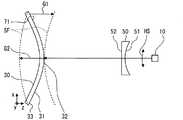
まず、ヘッドアップディスプレイ装置100の構成を、図1及び図2に基づいて説明する。ヘッドアップディスプレイ装置100は、レーザスキャナ10、スクリーン30、及び凹面鏡40を備えている。尚、以下の説明では、視認者に視認される虚像70の水平方向をx軸方向、鉛直方向をy軸方向とする。そして、各構成において投射、結像、及び投影される表示画像71のx軸方向を各構成における水平方向とし、y軸方向を各構成における鉛直方向とする。 First, the configuration of the head-up
レーザスキャナ10は、光源部13、光学部20、微小電気機械システム(Micro Electro Mechanical Systems;MEMS)ミラー26、及びコントローラ11を有している。 The
光源部13は、三つのレーザ投射部14,15,16等によって構成されている。各レーザ投射部14,15,16は、互いに異なる周波数、即ち異なる色相のレーザ光を投射する。具体的には、レーザ投射部14は、赤色のレーザ光を投射する。レーザ投射部15は、青色のレーザ光を投射する。レーザ投射部16は、緑色のレーザ光を投射する。以上のように、異なる色相のレーザ光を加色混合することにより、種々の色が再現可能とされている。各レーザ投射部14,15,16は、コントローラ11と接続されている。各レーザ投射部14,15,16は、コントローラ11からの制御信号に基づいて、各色相のレーザ光を投射する。 The
光学部20は、三つのコリメートレンズ21、ダイクロイックフィルタ22,23,24、及び集光レンズ25等によって構成されている。各コリメートレンズ21は、各レーザ投射部14,15,16のレーザ光の投射方向に、それぞれ配置されている。コリメートレンズ21は、レーザ光を屈折させることにより、平行光を生成する。 The
各ダイクロイックフィルタ22,23,24は、各コリメートレンズ21を挟んで各レーザ投射部14,15,16の投射方向に、それぞれ配置されている。ダイクロイックフィルタ22,23,24は、特定の周波数の光を反射させ、それ以外の周波数の光を透過させる。具体的には、レーザ投射部14の投射方向に配置されるダイクロイックフィルタ22は、赤色を示す周波数の光を反射させ、それ以外の周波数の光を透過させる。レーザ投射部15の投射方向に配置されるダイクロイックフィルタ23は、青色を示す周波数の光を反射させ、それ以外の周波数の光を透過させる。レーザ投射部16の投射方向に配置されるダイクロイックフィルタ24は、緑色を示す周波数の光を反射させ、それ以外の周波数の光を透過させる。各ダイクロイックフィルタ22,23,24は、集光レンズ25に向けてレーザ光を反射させる。 Each
集光レンズ25は、平面状の入射面及び凸面状の出射面を有する平凸レンズである。集光レンズ25は、入射面に入射するレーザ光を屈折させることにより、収束させる。これにより集光レンズ25を通過したレーザ光は、スクリーン30の後述する結像面31にて集光する。 The
MEMSミラー26は、コントローラ11と接続されており、全体として矩形板状を呈している。MEMSミラー26は、外枠部29、内枠部28、及びミラー部27等によって構成されている。 The
外枠部29は、内枠部28及びミラー部27の外周側を囲む矩形の枠状である。外枠部29は、レーザスキャナ10の筐体(図示しない)等によって固定されている。内枠部28は、外枠部29の内周側に配置されており、矩形の枠状に形成されている。内枠部28は、鉛直方向に延伸する低速軸28aによって外枠部29に支持されている。内枠部28は、低速軸28aまわりに回転変位可能である。外枠部29と内枠部28との間には、低速軸28aまわりに内枠部28を回転変位させる電極群(図示しない)が設けられている。 The
ミラー部27は、内枠部28の内周側に配置されており、円盤状に形成されている。ミラー部27の光学部20と対向する表面には、高効率での光の反射を実現するために、アルミニウム等を蒸着させた金属薄膜が形成されている。ミラー部27は、水平方向に延伸する高速軸27aによって内枠部28に支持されている。ミラー部27は、高速軸27aまわりに回転変位可能である。内枠部28とミラー部27との間には、高速軸27aまわりにミラー部27を回転変位させる電極群(図示しない)が設けられている。以上の構成によるMEMSミラー26は、コントローラ11によって出力される駆動信号に基づいて、外枠部29及び内枠部28間の電極群並びに内枠部28及びミラー部27間の電極群を各々作動させる。これによりミラー部27の向きは、鉛直方向(図2 矢印VS参照)及び水平方向(図2 矢印HS参照)に調整可能となる。 The
コントローラ11は、プロセッサ等によって構成される制御装置であって、各レーザ投射部14,15,16及びMEMSミラー26と接続されている。コントローラ11は、各レーザ投射部14,15,16に制御信号を出力することにより、レーザ光を断続的にパルス点灯させる。加えてコントローラ11は、MEMSミラー26に駆動信号を出力することにより、ミラー部27によって反射されるレーザ光の方向を、図2に示される走査線SLのように制御する。 The
レーザスキャナ10は、上述したコントローラ11の制御により、スクリーン30の後述する結像面31にて表示画像71として結像される光を投射する。具体的には、投射されるレーザ光による点状の発光の走査により、当該点状の発光を一つの画素として組み立てられる表示画像71が、スクリーン30の結像面31に描画される。このようなレーザスキャナ10の走査によって描画される表示画像71は、例えば、毎秒60フレームの画像であって、水平(x軸)方向及び鉛直(y軸)方向にそれぞれ480画素及び240画素を有する画像である。 The
スクリーン30は、ガラス等の基材の表面にアルミニウム等を蒸着させることにより形成される反射型のスクリーンである。スクリーン30は、車両の鉛直方向においてレーザスキャナ10の上方に配置されている(図3参照)。スクリーン30は、結像面31を有している。結像面31は、スクリーン30に蒸着されたアルミニウム等による金属薄膜によって、形成されている。結像面31には、レーザスキャナ10からyz面(図3参照)に沿ってレーザ光が投射されることにより、表示画像71が結像される。結像面31には、レーザ光を拡散するための微小な凹凸が形成されている。結像面31は、表示画像71を形成するレーザ光であって当該結像面31に入射するレーザ光を、拡散させつつ凹面鏡40に向けて反射させる。 The
凹面鏡40は、ガラス等の基材の表面にアルミニウム等を蒸着させることにより、形成されている。凹面鏡40は、スクリーン30の結像面31によって反射されたレーザ光をウィンドシールド90の投影面91に反射させる反射面41を有している。反射面41は、中央部分が結像面31及び投影面91から遠ざかる方向に凹む凹面状であって、滑らかに形成されている。反射面41は、結像面31によって反射された表示画像71を拡大しつつ反射させることにより、投影面91に当該表示画像71を投影する。この反射面41の湾曲による表示画像71の拡大率は、当該表示画像71の水平方向と鉛直方向とで異なっている。具体的には、反射面41では、表示画像71を鉛直方向よりも水平方向に大きく拡大するよう、水平方向の湾曲が鉛直方向の湾曲よりも大きくされている。 The
(特徴部分)
次に、本発明の一実施形態によるヘッドアップディスプレイ装置100の特徴部分について説明する。図1及び図3に示されるように、スクリーン30の結像面31は、凸面状に形成されている。加えて、レーザスキャナ10とスクリーン30との間には、自由曲面レンズ50が設けられている。以下、図3〜図6に基づいて、結像面31及び自由曲面レンズ50について詳細に説明する。(Characteristic part)
Next, features of the head-up
図3及び図4に示されるように、スクリーン30の結像面31は、当該結像面31に結像される表示画像71の鉛直方向及び水平方向のうち、水平方向に湾曲している。具体的には、辺縁部分33から中央部分32に向かうほど、レーザ光の進行(z軸)方向において凹面鏡40の反射面41、ひいては投影面91に近接する凸面状である。この結像面31の形状は、反射面41の湾曲及び投影面91の湾曲(図4では図示を省略)による虚像70の像面湾曲を補正するものである。 As shown in FIGS. 3 and 4, the
ここで、像面湾曲による虚像70の三次元的な歪みについて詳細に説明する。結像面31によって反射されたレーザ光は、湾曲した反射面41及び投影面91によってさらに反射される。この反射によって、結像される虚像70には像面湾曲による収差が生じる。具体的には、図4に示されるように、結像面31の辺縁部分33によって反射されるレーザ光は、結像面31の中央部分32によって反射されるレーザ光よりも、ウィンドシールド90に近い位置で結像する。故に、結像面が平坦である場合に、視認者に視認される表示画像71の虚像70は、中央部分70aから辺縁部分70bに向かうに従い、アイボックス60(図1参照)に近づく形状となる(図4 二点鎖線参照)。 Here, the three-dimensional distortion of the
そこで、結像面31は、虚像70の像面湾曲を補正する凸面状に形成される。この結像面31の形状によって、レーザ光の進行方向に沿った結像面31から投影面91までの光路距離は、結像面31の中央部分32から辺縁部分33に向かうに従い、遠くなる。故に、結像面31は、結像された虚像70の辺縁部分70bを中央部分70aよりも遠くに結像させる結像位置の調整作用を発揮する。このような調整作用により、像面湾曲によって投影面91に近接した虚像70の辺縁部分70bは、当該投影面91から遠ざけられる。以上により、虚像70の三次元的な歪みは、低減される。 Therefore, the
以上の結像面31が虚像70に与える効果を、表1に示される仕様での具体的なシミュレーション結果に基づいて、さらに詳細に説明する。表1には、凸面状の結像面31を備える仕様が示されている。この表1に示される結像面31は、水平(x軸)方向に二次の項を有している。故に、結像面31は、水平方向に放物線状に湾曲した形状である。また、表2には、平面状の結像面を備える仕様が示されている。そして、表1及び表2の各仕様において、アイボックス60内のアイポイント61から視認される虚像70のレーザ光のスポット径を、表3にて比較する。尚、スポット径とは、進行方向と直交する面におけるレーザ光の直径である。このスポット径が小さくなるほど、虚像70は、アイポイント61の位置変化に伴って動き難く、且つ鮮明となる。 The effect of the

表3に示されるように、凸面状の結像面31を用いることにより、虚像70の中央部分70aのスポット径が小さくなる。加えて、虚像70の全体における最大のスポット径も小さくなる。故に、虚像70は、アイポイント61の移動に伴って動き難く、且つ鮮明となる。 As shown in Table 3, by using the
次に、自由曲面レンズ50の作用を説明する。レーザスキャナ10によって投射されるレーザ光の集光する集光位置は、図5に示されるように当該スキャナ10を中心とした同心球面SF(図5 破線参照)上となる。故に、水平方向の走査(図5 矢印HS参照)が行われた際のレーザ光の集光位置は、凸面状である結像面31の形状によって、当該結像面31上から顕著にずれる。具体的に、結像面31の中央部分32に合わせて集光位置を規定した場合には、辺縁部分33の集光位置は、結像面31よりもレーザスキャナ10側にずれることとなる(図5 矢印G1参照)。一方で、結像面31の辺縁部分33に合わせて集光位置を規定した場合には、中央部分32の集光位置は、結像面31よりもレーザスキャナ10とは反対側にずれることとなる(図5 矢印G2参照)。以上により、結像面31に結像される表示画像71は、不鮮明になるおそれがある。 Next, the operation of the free-
そこで、レーザスキャナ10と結像面31との間に自由曲面レンズ50が設けられている。自由曲面レンズ50は、レーザ光の進行方向においてレーザスキャナ10と対向する自由曲面状の入射面51と、平面状の出射面52とを有するレンズであって、光学用のガラスによって形成されている。自由曲面レンズ50は、レーザスキャナ10によって投射されるレーザ光の集光する集光位置を結像面31上に調整する。具体的に、自由曲面レンズ50の入射面51は、水平方向において凹形状に形成されている。故に、結像面31の水平方向における辺縁部分33にて表示画像71を描画するレーザ光の集光位置は、レーザスキャナ10から遠ざかる。以上により、結像面31の中央部分32に合わせて集光位置を規定した場合でも、表示画像71の辺縁部分の集光位置は、結像面31上に位置し得る。このような自由曲面レンズ50の作用によって、レーザ光の集光位置は、結像面31の全域に亘って結像面31上に位置する。故に、表示画像71は、結像面31の全域に亘って鮮明に結像される。したがって、視認者によって視認される表示画像71の虚像70(図4参照)も、全体に亘って鮮明な像となる。 Therefore, a free-
以上の自由曲面レンズ50が虚像70に与える効果を、表4に示される仕様での具体的なシミュレーション結果に基づいて、さらに詳細に説明する。表4には、自由曲面レンズ50を備える仕様が示されている。この表4に示される自由曲面レンズ50の入射面51は、水平(x軸)方向において二次及び四次の項を有している。加えて、入射面51は、鉛直(y軸)方向において二次、三次、及び四次の項を有している。 The effect of the above-described free-
表4に示される自由曲面レンズ50において、水平方向の偶数次の項により、自由曲面レンズ50は、水平方向において凹形状に形成されている。レーザ光の集光位置は、湾曲する結像面31上に調整される。さらに、自由曲面レンズ50に奇数次である三次の項が含まれることにより、入射面51の鉛直方向における下半分は、レーザスキャナ10に向かって凸面状に突出する。一方で、入射面51の鉛直方向における上半分は、レーザスキャナ10に対して凹面状に窪む。このような入射面51の形状によれば、入射面51の下半分を通過して、結像面31の下半分に到達するレーザ光は、自由曲面レンズ50の省略された形態と比較して、レーザスキャナ10に近接する位置にて集光される。一方で、入射面51の上半分を通過して、結像面31の上半分に到達するレーザ光は、自由曲面レンズ50の省略された形態と比較して、レーザスキャナ10から離間する位置にて集光される。 In the free-
ここで、本実施形態では、レーザスキャナ10がスクリーン30の下方に配置されているので、レーザスキャナ10からスクリーン30までの距離は、鉛直方向に沿って上方に向かうに従い、拡大する。故に、上述の自由曲面レンズ50によって集光位置が調整されることによれば、yz面に沿って下方からレーザ光が投射される形態であっても、レーザ光の集光位置は、結像面31の全域に亘って当該結像面31上に調整され得る。このような作用を発揮する自由曲面レンズ50が設けられた場合と、省略された場合との比較を、表5に示す。 Here, in the present embodiment, since the
この表5に示されるように、レーザスキャナ10とスクリーン30との間に自由曲面レンズ50が設けられることにより、虚像70の中央部分70aにおけるスポット径は、わずかに大きくなる。しかし、虚像70の全体にいて最大となるスポット径は、小さくなる。故に、虚像70は、アイポイント61の移動に伴って動き難く、且つ全体に亘って鮮明となる。 As shown in Table 5, when the free-
ここまで説明した本実施形態において、アイボックス60内で視認者がアイポイント61を移動させた場合の虚像70の変化を、図6に基づいて説明する。図6(a)は、結像面31に結像される表示画像71の形状を示している。結像面が平面状である場合、視認者によって視認される虚像70は、図6(b)に示される形状となる。この虚像70は、水平方向に湾曲した形状となっている(図1及び図4の二点鎖線による虚像70参照)。故に、視認者がアイポイント61を例えば右方向に移動させた場合には、虚像70は、図6(c)に示される形状となる。具体的には、虚像70の右半分が水平方向に圧縮される一方で、虚像70の左半分は、水平方向に拡大される。加えて、虚像70が湾曲しているので、当該虚像70とアイポイント61との間の間隔は、当該アイポイント61の水平方向の動きによって変化する。故に、視認者がアイポイント61を移動させると、虚像70は、視認者に近づく。以上のように、虚像70の形状及び位置は、アイポイント61の移動によって大きく変化する。 In the present embodiment described so far, a change in the
対して、図6(d)に示されるのは、凸面状の結像面31による虚像70である。図6(d)に示される虚像70では、水平方向の湾曲が低減されている(図1及び図4の実線による虚像70参照)。この形態において、視認者がアイポイント61を右方向に移動させた場合には、虚像70は、図6(e)に示される形状となる。図6(e)に示される虚像70では、水平方向における右半分の圧縮及び左半分の拡大は、図6(c)に示される虚像70よりも低減されている。加えて、虚像70の湾曲が低減されているので、当該虚像70とアイポイント61との間の間隔は、当該アイポイント61の水平方向の動きによっては変化し難い。 In contrast, FIG. 6D shows a
以上の説明のように、本実施形態では、アイボックス60内において視認者がアイポイント61を移動させたとしても、視認者によって視認される虚像70の形状の変化及び位置の変化は、共に抑制される。したがって、虚像70として表示される表示画像71の表示品質の向上が、実現可能となる。 As described above, in this embodiment, even if the viewer moves the
加えて、虚像70の三次元的な歪みを低減するために結像面31を凸面状とした本実施形態であっても、自由曲面レンズ50が集光位置を調整する作用を発揮することにより、虚像70の鮮明さは失われ難い。したがって、表示画像71の表示品質を向上させる確実性を高めることが可能となる。 In addition, even in the present embodiment in which the
また本実施形態のように、凹面鏡40によって表示画像71が拡大される形態では、虚像70に生じる像面湾曲による三次元的な歪みも、拡大されてしまう。しかし、結像面31は、拡大された虚像70の拡大された三次元的な歪みを、調整作用の発揮によって低減し得る。故に、視認者に視認され易いように拡大されたうえで形状変化及び位置変化の抑制された虚像70が、視認可能となる。したがって、表示画像71の表示品質は、さらに向上可能となる。 Moreover, in the form in which the
さらに本実施形態では、凹面鏡40の反射面41は、表示画像71を鉛直方向よりも水平方向に大きく拡大する。この形態では、大きく拡大される水平方向の像面湾曲による歪みが、虚像70において顕著となる。そこで、結像面31は、水平方向に湾曲する凸面状とされる。故に、結像面31の調整作用は、顕著になる表示画像71の水平方向の歪みを効果的に低減し得る。加えて、水平方向に湾曲する簡素な形状の結像面31は形成容易であるので、スクリーン30の獲得が確実なものとなる。したがって、表示画像71の表示品質向上の実現性を高めることが可能となる。 Furthermore, in the present embodiment, the reflecting
また加えて本実施形態によれば、出力の高いレーザ光の走査によって結像面31に結像される表示画像71は、高いコントラストを備える。故に、虚像70は、高い視認性を獲得できる。このように高い視認性を有し且つ歪みの低減された虚像70を視認可能とするヘッドアップディスプレイ装置100は、優れた表示品質を獲得できる。 In addition, according to the present embodiment, the
さらに加えて本実施形態では、レーザスキャナ10に自由曲面レンズ50が組み合わされることにより、結像面31に結像される表示画像71は、当該自由曲面レンズ50の集光位置調整作用によってさらに鮮明なものとなる。故に、表示画像71の虚像70は、歪みが低減されたうえでさらに視認容易なものとなる。したがって、レーザスキャナ10は、自由曲面レンズ50と組み合わされることにより、表示画像71の表示品質向上に顕著に貢献できる。 In addition, in this embodiment, by combining the free-
さらに加えて本実施形態では、自由曲面レンズ50の入射面51及び出射面52のうち、主に入射面51が、レーザ光の集光位置を調整する作用を発揮する。入射面51を曲面状とすることにより、入射面51に入射するレーザ光の入射角度は、直角に近い角度となる。故に、レーザ光が自由曲面レンズ50を通過する際に生じる色収差が、低減可能となる。 In addition, in this embodiment, out of the
さらに、反射型のスクリーン30を用いることにより、レーザ光の光路の一部は、ヘッドアップディスプレイ装置100の内部にて折り返すように配置され得る。故に、光路の距離を確保しつつ、インスツルメントパネル内に収容可能なようにヘッドアップディスプレイ装置100を小型化することが、可能となる。 Further, by using the
尚、本実施形態において、レーザスキャナ10が特許請求の範囲に記載の「投影器」に相当し、スクリーン30が特許請求の範囲に記載の「スクリーン部材」に相当し、凹面鏡40が特許請求の範囲に記載の「拡大鏡部」に相当し、自由曲面レンズ50が特許請求の範囲に記載の「集光位置調整光学系」に相当し、アイボックス60が特許請求の範囲に記載の「視認領域」に相当し、ウィンドシールド90が特許請求の範囲に記載の「表示部材」に相当する。 In this embodiment, the
(他の実施形態)
以上、本発明による一実施形態について説明したが、本発明は、上記実施形態に限定して解釈されるものではなく、本発明の要旨を逸脱しない範囲内において種々の実施形態及び組み合わせに適用することができる。(Other embodiments)
As mentioned above, although one embodiment by the present invention was described, the present invention is not interpreted limited to the above-mentioned embodiment, and is applied to various embodiments and combinations within the range which does not deviate from the gist of the present invention. be able to.
上記実施形態では、ヘッドアップディスプレイ装置100によって表示画像71の投影される「表示部材」として、ウィンドシールド90が用いられていた。しかし、投影面の形成される「表示部材」は、ウィンドシールド90に限定されない。例えば、「表示部材」は、ウィンドシールド90の車内側の表面に貼りつけられた透光性の材料よりなるコンバイナ等であってもよい。 In the above embodiment, the
さらに、コンバイナは、ウィンドシールド90と別体で設けられていてもよい。このようなコンバイナが「表示部材」として用いられる形態では、「拡大鏡部」に相当する凹面鏡等は、省略されていてもよい。コンバイナの有する投影面が凹面状に湾曲していれば、運転者に視認される虚像は、結像面に結像された表示画像よりも拡大されたものとなる。故に、「拡大鏡部」の省略が可能となるのである。 Further, the combiner may be provided separately from the
又は、ウィンドシールドとは別体のコンバイナが「表示部材」として用いられる形態では、当該コンバイナは、平面状に形成されていてもよい。「拡大鏡部」によって所望の拡大率が獲得可能であれば、投影面の湾曲による拡大作用は、得られなくてもよくなる。故に、平面状の投影面に表示画像を投影する形態が、可能となるのである。 Alternatively, in a form in which a separate combiner from the windshield is used as the “display member”, the combiner may be formed in a planar shape. If a desired magnifying rate can be obtained by the “magnifying mirror”, the magnifying action due to the curvature of the projection surface may not be obtained. Therefore, it is possible to project a display image on a flat projection surface.
上記実施形態では、反射面41の湾曲及びの投影面91の湾曲によって、鉛直方向よりも水平方向に拡大された表示画像71の虚像70が、運転者に視認可能とされていた。故に、結像面31は、画角を要する水平方向における虚像70の歪みを効果的に抑制するように、水平方向にのみ湾曲する形状であった。しかし、水平方向及び鉛直方向における拡大率は、適宜変更されてよい。よって、鉛直方向における画角が必要な場合には、結像面は、水平方向に加えて鉛直方向にも湾曲する形状であってよい。具体的には、結像面の形状を規定する多項式(表1参照)は、yの偶数次(例えば二次)の項を含むことが望ましい。 In the above embodiment, the
上記実施形態では、反射型のスクリーン30が用いられていた。しかし、スクリーンは、凸面状に形成可能であれば、反射型のものに限定されない。例えば、透光性の材料によって形成された透過型のスクリーンが用いられてもよい。この形態では、レーザスキャナは、凸面状に形成された結像面の反対側であって、スクリーンを挟んで凹面鏡とは反対側から、表示画像を結像させるためのレーザ光を投射する。 In the above embodiment, the
上記実施形態では、スクリーン30の結像面31は、二次の項を含む放物線状の曲面であった。しかし、ウィンドシールドの形状、ひいては投影面の形状は、ヘッドアップディスプレイ装置の搭載される車種によって、様々である。故に、ウィンドシールド及び投影面が車両の鉛直方向に対して傾斜して設けられている場合には、結像面の形状を規定する多項式(表1参照)は、投影面の傾斜を補正するように、yの奇数次(例えば三次)の項を含むことが望ましい。 In the above embodiment, the
上記実施形態では、レーザスキャナ10とスクリーン30との間に設けられた自由曲面レンズ50が、「集光位置調整光学系」であった。しかし、自由曲面レンズ50に代えて自由曲面ミラーが、「集光位置調整光学系」として設けられていてもよい。ミラーを用いる形態では、集光位置の調整に際してレーザ光に生じる色収差の抑制が可能となる。又は、複数のレンズ及びミラー等によって、「集光位置調整光学系」が構成されていてもよい。或いは、レーザスキャナ10の備える集光レンズ25が、「集光位置調整光学系」の一部として構成されていてもよい。 In the above-described embodiment, the free-
上記実施形態では、自由曲面レンズ50は、出射面52が平面状であって、入射面51が自由曲面状に形成されていた。しかし、出射面が自由曲面状に形成され、入射面が平面状に形成されていてもよい。又は、出射面及び入射面が、共に自由曲面状に形成されていてもよい。或いは、単純な凹面状又は凸面状の曲面として、出射面及び入射面は形成されていてもよい。 In the above embodiment, the free-
上記実施形態では、結像面31の中央部分32に規定されたレーザ光の集光位置を自由曲面レンズ50の作用によって辺縁部分33にて遠ざけることにより、結像面31に結像される表示画像71は、全域に亘って鮮明化されていた。しかし、結像面31における光の集光位置は、中央部分32を基準に規定されなくてもよい。例えば、結像面31の辺縁部分33を基準として規定された光の集光位置が、自由曲面レンズ等の「集光位置調整光学系」の作用によって、結像面31の中央部分32にてレーザスキャナに近づけられてもよい。又は、中央部分32と辺縁部分33との中間を基準として規定された光の集光位置が、「集光位置調整光学系」の作用によって中央部分32ではレーザスキャナに近づけられ、且つ辺縁部分33ではレーザスキャナから遠ざけられてもよい。 In the embodiment described above, the laser beam condensing position defined in the
上記実施形態では、レーザスキャナ10から結像面31に向かう光軸は、yz面に沿っていた。このような形態に伴って、自由曲面レンズ50の形状を規定する多項式(表4参照)は、yの奇数次(三次)の項を含んでいた。しかし、ヘッドアップディスプレイ装置の搭載される車種のインスツルメントパネル内において確保可能なスペース、及びウィンドシールドの形状等により、結像面に対するレーザスキャナの相対位置は、適宜変更可能でなければならない。故に、自由曲面レンズの形状を規定する多項式は、レーザスキャナの配置に対応した項を含むことが望ましい。具体的には、レーザスキャナから結像面に向かう光軸がxz面に沿う形態、即ちレーザ光が結像面の側方から投影される形態では、自由曲面レンズ形状を規定する多項式は、xの奇数次の項を含むことが望ましい。さらに、レーザ光が結像面の斜め下方から投影される形態では、自由曲面レンズ形状を規定する多項式は、xの奇数次の項及びyの奇数次の項を共に含むことが望ましい。 In the embodiment described above, the optical axis from the
上記実施形態では、レーザ光の走査によって結像面31に表示画像71を結像させるレーザスキャナ10が、「投射器」として用いられていた。しかし、結像面にて表示画像として結像される光を投射することが可能であれば、種々の構成が「投射器」として用いられてよい。具体的には、例えばLiquid crystal on silicon(LCOS)及びDigital Mirror Device(DMD)等を、光源及びレンズ等の光学系と共に有する所謂プロジェクタが、「投射器」として用いられてよい。 In the above embodiment, the
LCOSは、シリコン製の基板と透光性の基板との間に液晶層を挟み込むことにより形成されている。液晶層は、配列された複数の画素を形成している。シリコン製の基板には、液晶を駆動するための回路と、光を反射するための電極が設けられている。LCOSに透光性の基板から入射した光源光は、液晶層を通過しつつ、シリコン製の基板に設けられた電極によって反射されて、当該LCOSから出射される。液晶層に表示画像の元となる画像を形成することによれば、LCOSを備えるプロジェクタは、結像面にて表示画像として結像される光を投射することができる。 LCOS is formed by sandwiching a liquid crystal layer between a silicon substrate and a translucent substrate. The liquid crystal layer forms a plurality of arranged pixels. A silicon substrate is provided with a circuit for driving liquid crystal and an electrode for reflecting light. The light source light incident on the LCOS from the light-transmitting substrate is reflected by the electrodes provided on the silicon substrate while passing through the liquid crystal layer and emitted from the LCOS. By forming an image serving as a source of a display image on the liquid crystal layer, a projector equipped with LCOS can project light that is imaged as a display image on an image plane.
DMDは、基板上に多数の微小鏡面を配列することにより形成されている。これら微小鏡面の各々が、一つの画素を形成している。各微小鏡面は、制御信号に基づいて傾斜角度を変更することができる。DMDに入射した光源光は、各微小鏡面によって反射される。以上のDMDは、各微小鏡面の傾斜角度を制御することによれば、画像を形成することができる。故に、DMDを備えるプロジェクタは、結像面にて表示画像として結像される光を投射することができる。 The DMD is formed by arranging a large number of micromirror surfaces on a substrate. Each of these micromirror surfaces forms one pixel. Each micro-mirror surface can change an inclination angle based on a control signal. The light source light incident on the DMD is reflected by each micromirror surface. The above DMD can form an image by controlling the inclination angle of each micromirror surface. Therefore, a projector equipped with a DMD can project light that is imaged as a display image on an imaging surface.
上記実施形態では、高速軸27a及び低速軸28aという複数の可動軸を有するMEMSミラー26が、レーザ光を走査する構成として用いられていた。しかし、レーザスキャナは、一つの可動軸を有するMEMSミラーを複数備える形態であってもよい。具体的には、水平方向にレーザ光を走査するための第一のMEMSミラーと鉛直方向にレーザ光を走査するための第二のMEMSミラーとを組み合わせた構成によって、二次元の表示画像を形成する上記実施形態のMEMSミラー26に相当する機能が実現されていてもよい。 In the above-described embodiment, the
上記実施形態では、車両のウィンドシールド90に表示画像71を投影するヘッドアップディスプレイ装置100に本発明を適用した例を示したが、本発明は、各種の輸送機器に搭載され、表示画像71の虚像70を視認者に視認可能とする種々のヘッドアップディスプレイ装置に適用することができる。 In the above-described embodiment, an example in which the present invention is applied to the head-up
10 レーザスキャナ(投射器)、11 コントローラ、13 光源部、14,15,16 レーザ投射部、20 光学部、21 コリメートレンズ、22,23,24 ダイクロイックフィルタ、25 集光レンズ、26 MEMSミラー、27 ミラー部、27a 高速軸、28 内枠部、28a 低速軸、29 外枠部、30 スクリーン(スクリーン部材)、31 結像面、32 中央部分、33 辺縁部分、40 凹面鏡(拡大鏡部)、41 反射面、50 自由曲面レンズ(集光位置調整光学系)、51 入射面、52 出射面、60 アイボックス(視認領域)、61 アイポイント、70 虚像、70a 中央部分、70b 辺縁部分、71 表示画像、90 ウィンドシールド(表示部材)、91 投影面、100 ヘッドアップディスプレイ装置、G1,G2 結像面からの集光位置のずれ量、HS 水平方向の走査範囲、VS 鉛直方向の査範囲、SF 同心球面、SL 走査線DESCRIPTION OF
Claims (5)
Translated fromJapanese前記投影面に投影される前記表示画像が結像され、当該投影面の湾曲による前記虚像の像面湾曲を補正する凸面状である結像面、を有するスクリーン部材と、
前記結像面にて前記表示画像として結像される光を、前記結像面の斜め下方向から投射する投射器と、
前記スクリーン部材の斜め下方向に位置する自由曲面レンズを有し、前記投射器によって斜め下方向から投射される光の集光する集光位置を、凸面状である前記結像面上に調整する集光位置調整光学系と、を備え、
前記自由曲面レンズは、入射面の鉛直方向の形状を規定する多項式に三次の項を含むことにより、前記入射面の鉛直方向における下半分を前記投射器に向かって凸面状に突出させて、前記結像面の下半分に到達する光の集光位置を前記投射器に近接させると共に、前記入射面の鉛直方向における上半分を前記投射器に対して凹面状に窪ませて、前記結像面の上半分に到達する光の集光位置を前記投射機から離間させることを特徴とするヘッドアップディスプレイ装置。A head-up display device that makes it possible to visually recognize a virtual image of the display image from a previously assumed visual recognition area by projecting the display image onto a concave projection surface formed on the display member,
The display image projected on the projection plane isimaged, a screen member having an imaging surface, Ruconvex der to correct the field curvature of the virtual image due to the curvature of the projection surface,
A projector that projects light imaged as the display image on the imagingsurface from an obliquely downward direction of the imaging surface ;
A free-form surface lens located obliquely below the screen member, and adjusting a condensing position for condensing light projected from the obliquely downward direction by the projector on the convex imaging surface;for example Beiand the focusing position adjustment optical system,the,
The free-form surface lens includes a third-order term in a polynomial that defines the shape of the incident surface in the vertical direction, so that the lower half of the incident surface in the vertical direction protrudes convexly toward the projector, and The focusing position of the light reaching the lower half of the imaging plane is brought close to the projector, and the upper half in the vertical direction of the incident plane is recessed concavely with respect to the projector, head-up display device according to claim Rukotothe condensing position of the light reaching the top half is separated from the projector of.
前記結像面は、前記投影面の湾曲による像面湾曲と共に前記反射面の湾曲による像面湾曲を補正する凸面状であることを特徴とする請求項1に記載のヘッドアップディスプレイ装置。A magnifying mirror having a concave reflecting surface for projecting the display image on the projection surface by reflecting the display image imaged on the imaging surface while enlarging,
The imaging surface, a head-up display device according to claim 1, wherein theconvex der Rukototo correct the field curvature due to the curvature of the reflecting surface with curvature due to the curvature of the projection surface.
前記投影面に投影される前記表示画像が結像される結像面、を有するスクリーン部材と、
前記結像面にて前記表示画像として結像される光を、前記結像面の斜め下方向から投射する投射器と、
前記結像面に結像された前記表示画像を拡大しつつ反射させることにより前記投影面に当該表示画像を投影する凹面状の反射面、を有する拡大鏡部と、
前記スクリーン部材の斜め下方向に位置する自由曲面レンズを有し、前記投射器によって斜め下方向から投射される光の集光する集光位置を、凸面状である前記結像面上に調整する集光位置調整光学系と、を備え、
前記結像面は、前記反射面の湾曲による前記虚像の像面湾曲を補正する凸面状であり、
前記自由曲面レンズは、入射面の鉛直方向の形状を規定する多項式に三次の項を含ことにより、前記入射面の鉛直方向における下半分を前記投射器に向かって凸面状に突出させて、前記結像面の下半分に到達する光の集光位置を前記投射器に近接させると共に、前記入射面の鉛直方向における上半分を前記投射器に対して凹面状に窪ませて、前記結像面の上半分に到達する光の集光位置を前記投射機から離間させることを特徴するヘッドアップディスプレイ装置。A head-up display device capable of visually recognizing a virtual image of the display image from a previously assumed visual recognition area by projecting a display image on a projection surface formed on the display member,
An image plane on which the display image projected on the projection plane is imaged;
A projector that projects light imaged as the display image on the imaging surface from an obliquely downward direction of the imaging surface;
A magnifying mirror unit having a concave reflecting surface that projects the display image on the projection surface by reflecting the display image formed on the imaging surface while enlarging the display image;
A free-form surface lens located obliquely below the screen member, and adjusting a condensing position for condensing light projected from the obliquely downward direction by the projector on the convex imaging surface; A condensing position adjusting optical system,
The imaging surface is a convex surface that corrects the curvatureof field of thevirtual imagedue to the curvature of the reflecting surface ;
The free-form surface lens includes a third-order term in a polynomial that defines the shape of the incident surface in the vertical direction so that the lower half of the incident surface in the vertical direction protrudes convexly toward the projector. The focusing position of the light reaching the lower half of the imaging plane is brought close to the projector, and the upper half in the vertical direction of the incident plane is recessed concavely with respect to the projector, light condensing position of the projector is spaced from the feature toRuhe Tsu windup display device Rukotoreaching the upper half of the.
前記結像面は、当該結像面に結像される前記表示画像の鉛直方向及び水平方向のうち水平方向に湾曲することにより、当該水平方向の像面湾曲を補正する凸面状であることを特徴とする請求項2又は3に記載のヘッドアップディスプレイ装置。The reflective surface has a concave shape that greatly enlarges the display image projected on the display member in a horizontal direction rather than a vertical direction,
The imaging surface has a convex shape that corrects thehorizontal curvature of fieldby curving in the horizontal direction among the vertical direction and the horizontal direction of the display image formed on the imaging surface.The head-up display device according toclaim 2, wherein the head-up display device isa head-up display device.
Priority Applications (5)
| Application Number | Priority Date | Filing Date | Title |
|---|---|---|---|
| JP2011161466AJP5370427B2 (en) | 2011-07-24 | 2011-07-24 | Head-up display device |
| US13/551,716US8766879B2 (en) | 2011-07-24 | 2012-07-18 | Head-up display apparatus |
| CN201210255052.4ACN102902064B (en) | 2011-07-24 | 2012-07-23 | Head-up display device |
| KR1020120080087AKR101408523B1 (en) | 2011-07-24 | 2012-07-23 | Head-up display apparatus |
| DE102012106638ADE102012106638A1 (en) | 2011-07-24 | 2012-07-23 | Head-up display device |
Applications Claiming Priority (1)
| Application Number | Priority Date | Filing Date | Title |
|---|---|---|---|
| JP2011161466AJP5370427B2 (en) | 2011-07-24 | 2011-07-24 | Head-up display device |
Publications (2)
| Publication Number | Publication Date |
|---|---|
| JP2013025205A JP2013025205A (en) | 2013-02-04 |
| JP5370427B2true JP5370427B2 (en) | 2013-12-18 |
Family
ID=47502304
Family Applications (1)
| Application Number | Title | Priority Date | Filing Date |
|---|---|---|---|
| JP2011161466AExpired - Fee RelatedJP5370427B2 (en) | 2011-07-24 | 2011-07-24 | Head-up display device |
Country Status (5)
| Country | Link |
|---|---|
| US (1) | US8766879B2 (en) |
| JP (1) | JP5370427B2 (en) |
| KR (1) | KR101408523B1 (en) |
| CN (1) | CN102902064B (en) |
| DE (1) | DE102012106638A1 (en) |
Cited By (3)
| Publication number | Priority date | Publication date | Assignee | Title |
|---|---|---|---|---|
| EP3012681A1 (en) | 2014-10-24 | 2016-04-27 | Ricoh Company, Ltd. | Image display device and apparatus |
| EP3067732A1 (en) | 2015-03-11 | 2016-09-14 | Ricoh Company, Limited | Image display apparatus |
| US10379342B2 (en) | 2014-09-18 | 2019-08-13 | Calsonic Kansei Corporation | Vehicular head-up display device |
Families Citing this family (92)
| Publication number | Priority date | Publication date | Assignee | Title |
|---|---|---|---|---|
| US10359545B2 (en) | 2010-10-21 | 2019-07-23 | Lockheed Martin Corporation | Fresnel lens with reduced draft facet visibility |
| US9632315B2 (en) | 2010-10-21 | 2017-04-25 | Lockheed Martin Corporation | Head-mounted display apparatus employing one or more fresnel lenses |
| AU2011343660A1 (en) | 2010-12-16 | 2013-07-04 | Lockheed Martin Corporation | Collimating display with pixel lenses |
| JP5900445B2 (en)* | 2013-02-06 | 2016-04-06 | 株式会社デンソー | Head-up display device |
| JP5949714B2 (en)* | 2013-02-06 | 2016-07-13 | 株式会社デンソー | Head-up display device |
| DE102013203616B4 (en)* | 2013-03-04 | 2019-10-24 | Sypro Optics Gmbh | Apparatus for projecting an image into a display area with screen for intermediate image display |
| WO2014155096A1 (en)* | 2013-03-28 | 2014-10-02 | Bae Systems Plc | Improvements in and relating to displays |
| JP6036482B2 (en) | 2013-03-29 | 2016-11-30 | 株式会社Jvcケンウッド | Image display device |
| JP2015034919A (en)* | 2013-08-09 | 2015-02-19 | 株式会社デンソー | Information display device |
| JP6115420B2 (en)* | 2013-09-17 | 2017-04-19 | 株式会社Jvcケンウッド | Image display device |
| EP2863115B1 (en)* | 2013-10-16 | 2018-04-25 | Continental Automotive GmbH | Head-up electronic-paper display system |
| TWI541543B (en) | 2013-10-21 | 2016-07-11 | 財團法人工業技術研究院 | Beam splitting module and projector device using the same |
| CN104554004B (en)* | 2013-10-23 | 2017-07-04 | 比亚迪股份有限公司 | A kind of new line digital display system |
| JP6127912B2 (en)* | 2013-10-28 | 2017-05-17 | 株式会社Jvcケンウッド | Image display device |
| KR101518932B1 (en) | 2013-12-18 | 2015-05-11 | 현대자동차 주식회사 | Display apparatus for vehicle |
| JP2015125317A (en)* | 2013-12-26 | 2015-07-06 | リコーインダストリアルソリューションズ株式会社 | Two-dimensional scanning laser beam projection device and two-dimensional distance-measuring equipment |
| WO2015098130A1 (en)* | 2013-12-26 | 2015-07-02 | リコーインダストリアルソリューションズ株式会社 | Two-dimensional scanning laser beam projection device and laser radar device |
| EP3088934A4 (en) | 2013-12-27 | 2017-03-29 | Panasonic Intellectual Property Management Co., Ltd. | Display equipment and display unit |
| KR102127853B1 (en) | 2013-12-31 | 2020-06-29 | 에스엘 주식회사 | Head up display apparatus and method for adjusting brightness of backlight unit |
| JP6187329B2 (en)* | 2014-01-06 | 2017-08-30 | 株式会社Jvcケンウッド | Virtual image display system |
| US9710987B2 (en)* | 2014-01-15 | 2017-07-18 | HLT Domestic IP, LLC | Systems and methods for use in acquiring credentials from a portable user device in unlocking door lock systems |
| KR20150100452A (en)* | 2014-02-25 | 2015-09-02 | 최해용 | High brightness head-up display device |
| JP2015194707A (en)* | 2014-03-27 | 2015-11-05 | パナソニックIpマネジメント株式会社 | Display device |
| JP6638198B2 (en)* | 2014-05-12 | 2020-01-29 | 株式会社リコー | Image display device and moving object |
| JP6555507B2 (en)* | 2014-05-12 | 2019-08-07 | 株式会社リコー | Image display device and moving body |
| JP6617947B2 (en)* | 2014-05-15 | 2019-12-11 | 株式会社リコー | Image display device and image display system |
| GB2526159B (en)* | 2014-05-16 | 2017-12-20 | Two Trees Photonics Ltd | Diffuser for head-up display |
| EP3152616B2 (en)* | 2014-06-03 | 2023-06-07 | MTT Innovation Incorporated | Efficient, dynamic, high contrast lensing with applications to imaging, illumination and projection |
| WO2015186488A1 (en)* | 2014-06-03 | 2015-12-10 | 矢崎総業株式会社 | Projection display device for vehicle |
| JP6334273B2 (en)* | 2014-06-03 | 2018-05-30 | 矢崎総業株式会社 | Projection display device for vehicle |
| BR112017001249A2 (en)* | 2014-07-22 | 2017-11-28 | Navdy Inc | compact heads-up display system |
| CN104216119A (en)* | 2014-08-20 | 2014-12-17 | 财团法人车辆研究测试中心 | Head-up display device |
| JP6381364B2 (en) | 2014-08-22 | 2018-08-29 | カルソニックカンセイ株式会社 | Head-up display device |
| US9373046B2 (en)* | 2014-09-10 | 2016-06-21 | Continental Automotive Systems, Inc. | Detection system for color blind drivers |
| WO2016047621A1 (en)* | 2014-09-24 | 2016-03-31 | 日本精機株式会社 | Head-up display device |
| US9547172B2 (en)* | 2014-10-13 | 2017-01-17 | Ford Global Technologies, Llc | Vehicle image display |
| JP6550716B2 (en)* | 2014-10-16 | 2019-07-31 | 日本精機株式会社 | Head-up display device |
| WO2016061447A1 (en)* | 2014-10-17 | 2016-04-21 | Lockheed Martin Corporation | Head-wearable ultra-wide field of view display device |
| JP6478151B2 (en)* | 2014-10-24 | 2019-03-06 | 株式会社リコー | Image display device and object device |
| US11347067B2 (en)* | 2014-12-12 | 2022-05-31 | Young Optics Inc. | Display system |
| JP6555568B2 (en)* | 2015-01-13 | 2019-08-07 | 株式会社リコー | Image display device |
| JP6295981B2 (en)* | 2015-02-25 | 2018-03-20 | 株式会社Jvcケンウッド | Image drawing apparatus, head-up display, and image brightness adjustment method |
| US9939650B2 (en) | 2015-03-02 | 2018-04-10 | Lockheed Martin Corporation | Wearable display system |
| DE102016203185A1 (en)* | 2015-03-11 | 2016-09-15 | Hyundai Mobis Co., Ltd. | Head-up display and control method for it |
| WO2016162928A1 (en)* | 2015-04-06 | 2016-10-13 | 日立マクセル株式会社 | Projection optical system and headup display device using same |
| JP6465353B2 (en)* | 2015-04-28 | 2019-02-06 | 日本精機株式会社 | Head-up display device |
| JP6492966B2 (en)* | 2015-05-22 | 2019-04-03 | 株式会社リコー | Light source unit and image display device |
| US10232139B1 (en) | 2015-06-12 | 2019-03-19 | Chrona Sleep, Inc. | Smart pillow cover and alarm to improve sleeping and waking |
| JP6516223B2 (en)* | 2015-06-30 | 2019-05-22 | パナソニックIpマネジメント株式会社 | Display device |
| WO2017022176A1 (en)* | 2015-08-06 | 2017-02-09 | パナソニックIpマネジメント株式会社 | Head-up display and moving body equipped with head-up display |
| JP6441197B2 (en) | 2015-09-25 | 2018-12-19 | 矢崎総業株式会社 | Scanning projector system |
| US10690911B2 (en) | 2015-10-09 | 2020-06-23 | Maxell, Ltd. | Projection optical system and head-up display device |
| WO2017061040A1 (en)* | 2015-10-09 | 2017-04-13 | 日立マクセル株式会社 | Projection optical system and head-up display device |
| WO2017061041A1 (en)* | 2015-10-09 | 2017-04-13 | 日立マクセル株式会社 | Projection optical system and head-up display device |
| CN111198442B (en)* | 2015-10-09 | 2022-03-01 | 麦克赛尔株式会社 | Head-up display device |
| US10754156B2 (en) | 2015-10-20 | 2020-08-25 | Lockheed Martin Corporation | Multiple-eye, single-display, ultrawide-field-of-view optical see-through augmented reality system |
| JP6672746B2 (en) | 2015-11-27 | 2020-03-25 | 株式会社リコー | Image display device and vehicle |
| JP6468206B2 (en)* | 2016-01-19 | 2019-02-13 | 株式会社デンソー | Head-up display device |
| TWM521179U (en)* | 2016-01-21 | 2016-05-01 | 中強光電股份有限公司 | Head-mounted display apparatus |
| US20190004314A1 (en)* | 2016-01-27 | 2019-01-03 | Kyocera Corporation | Head-up display for vehicle |
| US10571692B2 (en)* | 2016-03-02 | 2020-02-25 | Facebook Technologies, Llc | Field curvature corrected display |
| JP6409015B2 (en) | 2016-03-29 | 2018-10-17 | 矢崎総業株式会社 | Projection display device for vehicle |
| US9995936B1 (en) | 2016-04-29 | 2018-06-12 | Lockheed Martin Corporation | Augmented reality systems having a virtual image overlaying an infrared portion of a live scene |
| KR20180086476A (en)* | 2016-05-17 | 2018-07-31 | 쌩-고벵 글래스 프랑스 | Head-up display system |
| MA45012B1 (en) | 2016-05-17 | 2020-10-28 | Saint Gobain | Transparent glass |
| WO2017199441A1 (en)* | 2016-05-20 | 2017-11-23 | 日立マクセル株式会社 | Projection optical system, head-up display device, and automobile |
| JP6687851B2 (en)* | 2016-06-29 | 2020-04-28 | 株式会社Jvcケンウッド | Head up display device |
| JP6781930B2 (en) | 2016-07-06 | 2020-11-11 | 株式会社リコー | Optical scanning device, projection device and display device |
| WO2018066062A1 (en)* | 2016-10-04 | 2018-04-12 | マクセル株式会社 | Projection optical system, and head-up display device |
| CN109791284B (en)* | 2016-10-04 | 2021-07-06 | 麦克赛尔株式会社 | Projection optical system and head-up display device |
| CN108459457B (en)* | 2017-02-21 | 2021-10-08 | 宁波舜宇车载光学技术有限公司 | Image system and image adjusting method thereof |
| CN110573930B (en)* | 2017-03-03 | 2022-07-22 | 奥斯坦多科技公司 | Split-exit pupil head-up display system and method |
| JP2018144648A (en)* | 2017-03-06 | 2018-09-20 | 矢崎総業株式会社 | Display image projection system |
| JP2018146784A (en)* | 2017-03-06 | 2018-09-20 | 矢崎総業株式会社 | Display image projection device, and display image projection system |
| US11508257B2 (en)* | 2017-03-07 | 2022-11-22 | 8259402 Canada Inc. | Method to control a virtual image in a display |
| EP3608702A1 (en) | 2017-04-06 | 2020-02-12 | Panasonic Intellectual Property Management Co., Ltd. | Head-up display system, and mobile object provided with head-up display system |
| JP6717273B2 (en)* | 2017-08-07 | 2020-07-01 | 株式会社デンソー | Head up display device |
| CN107784962A (en)* | 2017-12-04 | 2018-03-09 | 贵州晶源动力科技有限公司 | Project digital advertisement cabinet and digital advertisement system |
| CN108490616B (en)* | 2018-04-03 | 2020-04-10 | 京东方科技集团股份有限公司 | Head-up display and display control method |
| JP7049583B2 (en)* | 2018-07-26 | 2022-04-07 | コニカミノルタ株式会社 | Head-up display device |
| US11109004B2 (en)* | 2018-07-31 | 2021-08-31 | Texas Instruments Incorporated | Display with increased pixel count |
| JP2020071475A (en)* | 2018-10-25 | 2020-05-07 | 株式会社リコー | Display unit, display system, and movable body |
| EP3644108A1 (en)* | 2018-10-25 | 2020-04-29 | Ricoh Company, Ltd. | Display device, display system, and mobile object |
| JP6795796B2 (en)* | 2019-08-22 | 2020-12-02 | 株式会社リコー | Image display device |
| US11360302B2 (en)* | 2019-10-16 | 2022-06-14 | Panasonic Automotive Systems Company Of America, Division Of Panasonic Corporation Of North America | Curved virtual image for heads up display |
| GB201915455D0 (en)* | 2019-10-24 | 2019-12-11 | Cambridge Entpr Ltd | Ghost image free head-up display |
| CN114397756A (en)* | 2020-05-15 | 2022-04-26 | 华为技术有限公司 | A display device and display system |
| JP7278447B2 (en)* | 2020-07-22 | 2023-05-19 | マクセル株式会社 | vehicle |
| JP7146862B2 (en)* | 2020-08-13 | 2022-10-04 | 矢崎総業株式会社 | vehicle display |
| CN112147784A (en)* | 2020-09-29 | 2020-12-29 | 江苏泽景汽车电子股份有限公司 | Turn-back type AR-HUD (augmented reality-high-definition) far and near view double-screen imaging system |
| KR102562527B1 (en)* | 2020-12-09 | 2023-08-02 | 광운대학교 산학협력단 | Floating hologram system using holographic optical element |
| CN112731667A (en)* | 2021-01-05 | 2021-04-30 | 业成科技(成都)有限公司 | Projection device and projection method |
Family Cites Families (18)
| Publication number | Priority date | Publication date | Assignee | Title |
|---|---|---|---|---|
| US4348187A (en)* | 1980-07-31 | 1982-09-07 | The Singer Company | Aerial image visual display |
| US4509835A (en)* | 1983-09-06 | 1985-04-09 | Adler Clarence E | Three dimensional cinema and novel projector system therefore |
| US4711544A (en) | 1985-04-12 | 1987-12-08 | Yazaki Corporation | Display system for vehicle |
| JPH0434126A (en) | 1990-05-29 | 1992-02-05 | Kubota Corp | Back hoe |
| JPH0434126U (en)* | 1990-07-19 | 1992-03-19 | ||
| JPH0667154A (en) | 1992-08-14 | 1994-03-11 | Semiconductor Energy Lab Co Ltd | Method for driving liquid crystal electrooptical device |
| JP3418985B2 (en) | 1992-12-14 | 2003-06-23 | 株式会社デンソー | Image display device |
| JPH07257225A (en) | 1994-03-22 | 1995-10-09 | Asahi Glass Co Ltd | Holographic display system |
| JPH10149085A (en) | 1996-11-20 | 1998-06-02 | Asahi Glass Co Ltd | Holographic display device |
| JPH1130764A (en) | 1997-07-11 | 1999-02-02 | Shimadzu Corp | Display device |
| KR20030000536A (en)* | 2001-06-26 | 2003-01-06 | 현대자동차주식회사 | Head-up display for vehicles |
| JP4033081B2 (en)* | 2003-08-27 | 2008-01-16 | 株式会社デンソー | Vehicle display device |
| JP4481625B2 (en)* | 2003-11-27 | 2010-06-16 | キヤノン株式会社 | Two-dimensional scanning device and scanning image display device using the same |
| KR100891664B1 (en)* | 2007-05-11 | 2009-04-02 | 엘지전자 주식회사 | Display device |
| US7688516B2 (en) | 2007-05-11 | 2010-03-30 | Lg Electronics Inc. | Head-up display device for vehicles |
| JP5304380B2 (en)* | 2008-07-23 | 2013-10-02 | 株式会社リコー | Optical scanning device, image projection device using the same, head-up display device, and mobile phone |
| US7663793B1 (en)* | 2008-07-31 | 2010-02-16 | Institut National D'optique | Wide angle immersive display system |
| JP5270012B2 (en)* | 2010-02-10 | 2013-08-21 | 株式会社東芝 | Display device, display method, and moving body |
- 2011
- 2011-07-24JPJP2011161466Apatent/JP5370427B2/ennot_activeExpired - Fee Related
- 2012
- 2012-07-18USUS13/551,716patent/US8766879B2/ennot_activeExpired - Fee Related
- 2012-07-23CNCN201210255052.4Apatent/CN102902064B/ennot_activeExpired - Fee Related
- 2012-07-23KRKR1020120080087Apatent/KR101408523B1/ennot_activeExpired - Fee Related
- 2012-07-23DEDE102012106638Apatent/DE102012106638A1/ennot_activeCeased
Cited By (7)
| Publication number | Priority date | Publication date | Assignee | Title |
|---|---|---|---|---|
| US10379342B2 (en) | 2014-09-18 | 2019-08-13 | Calsonic Kansei Corporation | Vehicular head-up display device |
| EP3012681A1 (en) | 2014-10-24 | 2016-04-27 | Ricoh Company, Ltd. | Image display device and apparatus |
| US10078217B2 (en) | 2014-10-24 | 2018-09-18 | Ricoh Company, Ltd. | Image display device and apparatus |
| EP3067732A1 (en) | 2015-03-11 | 2016-09-14 | Ricoh Company, Limited | Image display apparatus |
| US9864195B2 (en) | 2015-03-11 | 2018-01-09 | Ricoh Company, Ltd. | Image display apparatus |
| US10191274B2 (en) | 2015-03-11 | 2019-01-29 | Ricoh Company, Ltd. | Image display apparatus |
| US10613321B2 (en) | 2015-03-11 | 2020-04-07 | Ricoh Company, Ltd. | Image display apparatus |
Also Published As
| Publication number | Publication date |
|---|---|
| DE102012106638A1 (en) | 2013-01-24 |
| CN102902064A (en) | 2013-01-30 |
| US20130021224A1 (en) | 2013-01-24 |
| KR101408523B1 (en) | 2014-06-17 |
| KR20130012109A (en) | 2013-02-01 |
| CN102902064B (en) | 2015-08-26 |
| US8766879B2 (en) | 2014-07-01 |
| JP2013025205A (en) | 2013-02-04 |
Similar Documents
| Publication | Publication Date | Title |
|---|---|---|
| JP5370427B2 (en) | Head-up display device | |
| KR101344129B1 (en) | Head-up display apparatus | |
| JP5310810B2 (en) | Head-up display device | |
| TWI541543B (en) | Beam splitting module and projector device using the same | |
| CN108431668B (en) | Head-up display device | |
| JP2016206612A (en) | Image display device and object device | |
| WO2016027706A1 (en) | Projection device and head-up display device | |
| CN107430274A (en) | Projection optical system and the head-up display device using projection optical system | |
| JP6579180B2 (en) | Virtual image display device | |
| CN111213114A (en) | Information display device and space sensing device thereof | |
| JPWO2017138431A1 (en) | Display device and head-up display | |
| JP2018205621A (en) | Virtual image display device, intermediate image forming unit, and image display light generation unit | |
| JP2019211780A (en) | Image display device | |
| WO2018123528A1 (en) | Display device and moving body carrying display device | |
| JP7021939B2 (en) | Information display device | |
| JP2020064235A (en) | Display device | |
| TW201723585A (en) | Head-up display | |
| JP6611310B2 (en) | Projection display device for vehicle | |
| JP2018040842A (en) | Head-up display device | |
| JP6609484B2 (en) | In-vehicle display device | |
| JP2019045605A (en) | Head-up display device | |
| JP6315943B2 (en) | Projection optical system | |
| JP2018194820A (en) | Virtual image forming apparatus and moving body | |
| WO2018030203A1 (en) | Display device | |
| JP2018105939A (en) | Head-up display device |
Legal Events
| Date | Code | Title | Description |
|---|---|---|---|
| A621 | Written request for application examination | Free format text:JAPANESE INTERMEDIATE CODE: A621 Effective date:20121217 | |
| A977 | Report on retrieval | Free format text:JAPANESE INTERMEDIATE CODE: A971007 Effective date:20130517 | |
| A131 | Notification of reasons for refusal | Free format text:JAPANESE INTERMEDIATE CODE: A131 Effective date:20130528 | |
| A521 | Written amendment | Free format text:JAPANESE INTERMEDIATE CODE: A523 Effective date:20130729 | |
| TRDD | Decision of grant or rejection written | ||
| A01 | Written decision to grant a patent or to grant a registration (utility model) | Free format text:JAPANESE INTERMEDIATE CODE: A01 Effective date:20130820 | |
| A61 | First payment of annual fees (during grant procedure) | Free format text:JAPANESE INTERMEDIATE CODE: A61 Effective date:20130902 | |
| R151 | Written notification of patent or utility model registration | Ref document number:5370427 Country of ref document:JP Free format text:JAPANESE INTERMEDIATE CODE: R151 | |
| R250 | Receipt of annual fees | Free format text:JAPANESE INTERMEDIATE CODE: R250 | |
| R250 | Receipt of annual fees | Free format text:JAPANESE INTERMEDIATE CODE: R250 | |
| R250 | Receipt of annual fees | Free format text:JAPANESE INTERMEDIATE CODE: R250 | |
| LAPS | Cancellation because of no payment of annual fees |