JP5370286B2 - Fluorescence detection device - Google Patents
Fluorescence detection deviceDownload PDFInfo
- Publication number
- JP5370286B2 JP5370286B2JP2010147961AJP2010147961AJP5370286B2JP 5370286 B2JP5370286 B2JP 5370286B2JP 2010147961 AJP2010147961 AJP 2010147961AJP 2010147961 AJP2010147961 AJP 2010147961AJP 5370286 B2JP5370286 B2JP 5370286B2
- Authority
- JP
- Japan
- Prior art keywords
- measurement
- excitation light
- temperature
- light
- fluorescence
- Prior art date
- Legal status (The legal status is an assumption and is not a legal conclusion. Google has not performed a legal analysis and makes no representation as to the accuracy of the status listed.)
- Active
Links
Images


Landscapes
- Investigating, Analyzing Materials By Fluorescence Or Luminescence (AREA)
Abstract
Description
Translated fromJapanese本発明は、検体に励起光を照射することにより検体を励起して蛍光を発生させ、その蛍光の強度から測定対象物の濃度を測定する方法及び装置に関するものである。 The present invention relates to a method and apparatus for exciting a specimen to generate fluorescence by irradiating the specimen with excitation light, and measuring the concentration of a measurement object from the intensity of the fluorescence.
例えば核酸増幅プロセス(以下、PCR反応)において、増幅生成物の生成量を蛍光検出によって測定することが行なわれている。PCR反応を行なう検体に蛍光標識を含ませ、励起光を照射して検体を励起することにより蛍光を発生させる。蛍光標識から発せられる蛍光の強度は増幅生成物の増加に伴なって変化するため、蛍光強度を検出することにより増幅生成物の生成量を追跡することができる。 For example, in a nucleic acid amplification process (hereinafter referred to as PCR reaction), the amount of amplification product produced is measured by fluorescence detection. Fluorescence is generated by including a fluorescent label in the specimen to be subjected to the PCR reaction and exciting the specimen by irradiating excitation light. Since the intensity of the fluorescence emitted from the fluorescent label changes as the amplification product increases, the amount of amplification product produced can be traced by detecting the fluorescence intensity.
しかし、蛍光標識の発光強度には温度特性があり、PCR反応における温度変化によって蛍光標識からの蛍光の発光強度が変化するため、蛍光の測定値にそのような温度変化による影響を含むことになる。そのため、蛍光標識の発光強度の温度特性に基づいて検出強度の測定値を所定の基準値のものに換算する補正を行なっていた。 However, the emission intensity of the fluorescent label has a temperature characteristic, and the fluorescence emission intensity from the fluorescent label changes due to the temperature change in the PCR reaction. Therefore, the measurement value of fluorescence includes the effect of such temperature change. . For this reason, the measurement value of the detected intensity is corrected to a predetermined reference value based on the temperature characteristic of the emission intensity of the fluorescent label.
しかし、励起光を照射する光源としての発光ダイオード(以下、LED)においても励起光の発光強度に温度特性をもつものがある。そのようなLEDを用いて蛍光検出を行なった場合には、PCR反応における温度変化によって発光強度が変化し、検出強度の測定値に蛍光標識の発光強度の温度特性による影響とLEDの発光強度の温度特性による影響が含まれていることになる。そのような場合に、検出強度の測定値を蛍光標識の発光強度の温度依存特性に基づいて補正してもLEDの温度特性による影響が残るため、増幅生成物の生成量に応じて蛍光標識から発せられる正確な蛍光強度の値が得られなかった。 However, some light emitting diodes (hereinafter referred to as LEDs) as light sources for irradiating excitation light have temperature characteristics in the emission intensity of the excitation light. When fluorescence detection is performed using such an LED, the emission intensity changes due to a temperature change in the PCR reaction, and the measured intensity of the fluorescent label depends on the temperature characteristics of the emission intensity of the fluorescent label and the emission intensity of the LED. The effect of temperature characteristics is included. In such a case, even if the measurement value of the detected intensity is corrected based on the temperature-dependent characteristic of the emission intensity of the fluorescent label, the effect of the temperature characteristic of the LED remains. The exact fluorescence intensity value to be emitted could not be obtained.
上記問題を解決するために、実際の測定に使用されるLEDと同じ仕様の対照用LEDを設けてその光量を同時に測定して対照光とすることにより、測定値の補正を行なうことが提案されている(特許文献1参照。)。 In order to solve the above problem, it has been proposed to correct the measured value by providing a reference LED having the same specifications as the LED used for actual measurement, and simultaneously measuring the amount of light as a reference light. (See Patent Document 1).
しかし、温度特性の大きなLEDでは、測定用LEDと対照用LEDとが同じ仕様のLEDであっても固体間の温度特性の差が存在するため、同じ温度特性を示すとは限らない。例えば、数ワット級の高輝度LEDを使用する場合、LEDとその基板の密着具合によってはLED素子自体の温度上昇に差が生じて輝度のばらつきが生じる。したがって、対照用LEDと測定用LEDで異なる個体のLEDを使用すると、両者間で輝度に差が生じ、正確な補正を行なうことはできない。 However, an LED having a large temperature characteristic does not necessarily exhibit the same temperature characteristic because there is a difference in temperature characteristic between solids even if the measurement LED and the control LED have the same specifications. For example, when a high-brightness LED of several watts is used, a difference in the temperature rise of the LED element itself occurs depending on the close contact between the LED and its substrate, resulting in luminance variations. Therefore, when different LEDs are used for the control LED and the measurement LED, a difference in luminance occurs between them, and accurate correction cannot be performed.
そこで本発明は、検体から発せられる蛍光強度の測定値を光源の発光強度の温度特性による影響を除去したものに補正できるようにすることを目的とするものである。 Accordingly, an object of the present invention is to make it possible to correct a measured value of fluorescence intensity emitted from a specimen to a value obtained by removing the influence of temperature characteristics of the light emission intensity of a light source.
光源の温度特性による測定結果への影響を除去するための原理について説明する。温度変化による光源の発光強度の変化を調べるために、測定用の励起光を発する測定光源とは別に参照用の励起光を発する参照光源を使用し、これらの光源からの励起光を照射したときの蛍光の強度を測定するために基準物質を使用する。 The principle for removing the influence of the temperature characteristics of the light source on the measurement result will be described. When investigating excitation light from these light sources, a reference light source that emits reference excitation light is used in addition to the measurement light source that emits excitation light for measurement, in order to investigate changes in the emission intensity of the light source due to temperature changes. A reference material is used to measure the intensity of fluorescence.
参照光源としては、例えば分析を行なう環境温度の範囲内では発光強度を一定とみなすことができるもの、例えば青色発光ダイオードを使用する。「一定とみなすことができる」とは、温度によってその発光強度が変化するものの、その変化量が3%以下であることを意味する。例えば青色発光ダイオードは、10℃〜35℃の間の環境温度変化においてその発光強度の変化率が1%程度であり、一定とみなすことができるものである。 As the reference light source, for example, a blue light-emitting diode that can be regarded as having a constant emission intensity within the range of the ambient temperature for analysis is used. “Can be regarded as constant” means that although the emission intensity varies with temperature, the variation is 3% or less. For example, a blue light-emitting diode can be regarded as constant because the change rate of the light emission intensity is about 1% when the environmental temperature changes between 10 ° C. and 35 ° C.
基準物質としては、測定光源からの測定励起光、参照光源からの参照励起光のいずれの励起光によっても励起されて蛍光を発生させ、その発光効率の温度特性が励起光の波長の違いに影響されない物質である。そのような基準物質としては、例えば硫化カドミウム(CdS)とセレン(Se)を添加したガラスを用いることができる。「発光効率の温度特性が励起光の波長の違いに影響されない」とは、励起光の波長の違いによる発光効率の差が分析を行なう環境温度の範囲内では±5%以内であり、無視することができる程度に小さいことを意味する。
As a reference material, fluorescence is excited by excitation light of either measurement excitation light from a measurement light source or reference excitation light from a reference light source, and the temperature characteristics of the emission efficiency affect the difference in wavelength of the excitation light. It is a substance that is not. As such a reference material, for example, glass added with cadmium sulfide (CdS) and selenium (Se) can be used. “The temperature characteristic of the luminous efficiency is not affected by the difference in the wavelength of the excitation light” means that the difference in the luminous efficiency due to the difference in the wavelength of the excitation light is within ± 5% within the range of the ambient temperature for analysis, and is ignored. It is small enough to be able to.
基準時に基準温度T0(例えば25℃)の条件下で、基準物質に参照励起光を照射したときの基準物質からの蛍光強度をIA(T0)、基準物質に測定励起光を照射したときの基準物質からの蛍光強度をIB(T0)とする。測定時に測定温度Tにおける参照光源の相対輝度をΦA(T)(基準時を1とする)、測定光源の相対輝度をΦB(T)(基準時を1とする)とする。参照光源の輝度は温度変化に影響されないため、ΦA(T)=1とみなすことができる。ΦB(T)が測定光源の温度特性による影響を意味するものであり、最終的にΦB(T)に基づいて補正することを目的としている。Under conditions of standard temperature T0 (for example 25 ° C.)to the reference time, IA (T0) the fluorescence intensity of the reference material when irradiated with reference excitation light as a reference material was irradiated with measurement excitation light as a reference material The fluorescence intensity from the reference material at this time is defined as IB (T0 ).At the time of measurement, the relative luminance of the reference light sourceat the measurement temperature T is ΦA (T) (reference time is 1), and the relative luminance of themeasurement light source is ΦB (T) (reference time is 1). Since the luminance of the reference light source is not affected by the temperature change, it can be considered that ΦA (T) = 1. ΦB (T) means the influence of the temperature characteristics of the measurement light source, and is intended to be corrected finally based on ΦB (T).
測定時に測定温度Tの条件下で、基準物質を参照励起光により励起したときの基準物質の発光効率をaA(T)(基準時を1とする)、測定時において測定励起光により基準物質を励起したときの基準物質の発光効率はaB(T)(基準時を1とする)とする。ここで、励起光の波長の違いが基準物質の蛍光強度に与える影響は無視できる程度に小さいため、aA(T)=aB(T)とみなすことができる。Under the conditions of measurement temperature Tat the time of measurement, the emission efficiency of the reference material when excited by reference excitation light reference material (a 1 areference time) aA (T), the reference material by measuring the pumping light at thetime of measurement The emission efficiency of the reference substance when is excited is aB (T) (thereference time is 1). Here, since the influence of the difference in wavelength of the excitation light on the fluorescence intensity of the reference material is so small as to be negligible, it can be regarded as aA (T) = aB (T).
測定時に測定温度Tの条件下で、参照励起光により基準物質を励起して得られる蛍光の信号強度IA(T)は次式(1)で表わすことができる。
IA(T)=IA(T0)・ΦA(T)・aA(T)=IA(T0)・aA(T) (1)
同様に、測定時における測定励起光により基準物質を励起して得られる蛍光の信号強度IB(T)は次式(2)で表わすことができる。
IB(T)=IB(T0)・ΦB(T)・aB(T) (2)The signal intensity IA (T) of the fluorescence obtained by exciting the standard substance with the reference excitation light under the condition of the measurement temperature Tat the time of measurement can be expressed by the following formula (1).
IA (T) = IA (T0 ) · ΦA (T) · aA (T) = IA (T0 ) · aA (T) (1)
Similarly, the fluorescence signal intensity IB (T) obtained by exciting the reference material with the measurement excitation lightat the time of measurement can be expressed by the following equation (2).
IB (T) = IB (T0 ) · ΦB (T) · aB (T) (2)
上記(1),(2)式より、
ΦB(T)=IA(T0)/IB(T0)・IB(T)/IA(T) (3)
となる。測定時に測定された検体からの蛍光強度の測定値I(T)から測定励起光の温度変化に温度変化分を除去するためにはI(T)をΦB(T)で割ればよい。したがって、補正値I'(T)は、次式(4)で表わすことができる。
I'(T)=I(T)・IB(T0)/IA(T0)・IA(T)/IB(T) (4)From the above formulas (1) and (2),
ΦB (T) = IA (T0 ) / IB (T0 ) · IB (T) / IA (T) (3)
It becomes.In order to remove the temperature change from the measurement value I (T) of the fluorescence intensity from the samplemeasured at the time of measurement to the temperature change of the measurement excitation light, I (T) may be divided by ΦB (T). Therefore, the correction value I ′ (T) can be expressed by the following equation (4).
I ′ (T) = I (T) · IB (T0 ) / IA (T0 ) · IA (T) / IB (T) (4)
本発明の蛍光測定方法は上記理論を用いたものである。すなわち、光源として参照光源と測定光源とを用い、基準時に基準温度T0の条件下で基準物質に対して参照励起光と測定励起光をそれぞれ照射したときに得られる蛍光強度IA(T0),IB(T0)を測定する基準時補正要素測定工程と、測定時に測定温度Tの条件下で検体に測定励起光を照射して得られる蛍光強度I(T)を測定する検体測定工程と、測定時に測定温度Tの条件下で基準物質に参照励起光と測定励起光をそれぞれ照射して得られる蛍光強度IA(T),IB(T)を測定する測定時補正要素測定工程と、次式により得られるI'(T)に基づいて測定対象物の濃度を求める演算処理工程と、を行なう方法である。
I'(T)=I(T)・IA(T)/IB(T)・IB(T0)/IA(T0)
The fluorescence measurement method of the present invention uses the above theory. That is, the reference light source and the measurement light source used as the light source, the fluorescent intensity obtainedwhen the reference time and the reference temperature T reference excitation light relative to the standard under the conditions of0 measured excitation light was irradiated respectively IA (T0 ), IB (T0 ) for measuringreference correction element, and sample measurement for measuring fluorescence intensity I (T) obtained by irradiating the sample with measurement excitation lightat the measurement temperature Tat the time of measurement Correction factor measurementat the time of measuring the fluorescence intensity IA (T), IB (T) obtained by irradiating the reference material with the reference excitation light and the measurement excitation light under the conditions of the measurement temperature Tat the time of measurement and measurement This is a method of performing a process and an arithmetic processing process for obtaining the concentration of the measurement object based on I ′ (T) obtained by the following equation.
I ′ (T) = I (T) · IA (T) / IB (T) · IB (T0 ) / IA (T0 )
本発明の蛍光検出装置は、上記蛍光測定方法を実行するための構成及び機能を備えた装置である。具体的には、参照励起光を発生させその発光強度を測定温度範囲においては温度に拘わらず一定とみなすことができる参照光源と、参照励起光とは異なる波長をもつ測定励起光を発生させその発光強度に温度特性を有する測定光源と、検体を配置するための検体配置部と、参照励起光と測定励起光のそれぞれにより励起されて蛍光を発生させ、その発光効率の温度特性が励起光の波長の違いに影響されない基準物質を配置するための基準物質配置部と、入射した光の強度を検出する光検出器と、参照光源からの参照励起光を検体配置部又は基準物質配置部に導く参照光学系と、測定光源からの測定励起光を検体配置部又は基準物質配置部に導く測定光学系と、検体又は基準物質から発せられた蛍光を光検出器に導く蛍光光学系と、参照光源、測定光源及び光検出器を制御する制御部と、光検出器の信号強度に基づいて測定対象物の濃度を求める演算処理部と、基準物質に対し、基準温度T0の条件下で参照励起光を照射したときの蛍光強度IA(T0)及び基準温度T0の条件下で測定励起光を照射したときの蛍光強度IB(T0)を保持する補正要素保持部と、を備えている。そして、制御部は、測定対象の検体に対し、測定温度Tの条件下で測定励起光を照射したときの検体からの蛍光強度I(T)を測定するように構成された検体測定手段と、基準物質に対し、測定温度Tの条件下で参照励起光を照射したときの基準物質からの蛍光強度IA(T)及び測定励起光を照射したときの基準物質からの蛍光強度IB(T)を測定するように構成された測定温度時補正要素測定手段と、を備えている。演算処理部は次式により得られるI'(T)に基づいて測定対象物の濃度を求めるように構成されているものである。
I'(T)=I(T)・IA(T)/IB(T)・IB(T0)/IA(T0)The fluorescence detection apparatus of the present invention is an apparatus having a configuration and a function for executing the fluorescence measurement method. Specifically, the reference excitation light is generated and the emission intensity of the reference excitation light is considered to be constant regardless of the temperature in the measurement temperature range, and the measurement excitation light having a wavelength different from that of the reference excitation light is generated. A measurement light source having a temperature characteristic in emission intensity, a specimen placement unit for placing a specimen, and fluorescence generated by being excited by each of the reference excitation light and the measurement excitation light. Reference material placement unit for placing a reference material that is not affected by the difference in wavelength, a photodetector that detects the intensity of incident light, and reference excitation light from a reference light source is guided to the specimen placement unit or the reference material placement unit A reference optical system, a measurement optical system that guides measurement excitation light from the measurement light source to the specimen placement part or the reference substance placement part, a fluorescence optical system that guides fluorescence emitted from the specimen or reference material to the photodetector, and a reference light source , A control unit for controlling the Teikogen and a photodetector, and a processing unit for determining the concentration of the measurement object based on the signal intensity of the photodetector, with respect to the reference material, the reference excitation light under the conditions of the reference temperature T0 provided with a correction element holding portion for holding the fluorescent intensity when irradiated with Ia (T0) and fluorescence intensity IB (T0) at the time of irradiation with measured excitation light under the conditions of the reference temperature T0 Yes. And a control unit configured to measure the fluorescence intensity I (T) from the sample when the sample to be measured is irradiated with the measurement excitation light under the condition of the measurement temperature T; Fluorescence intensity IA (T) from the standard substance when the reference substance is irradiated with the reference excitation light at the measurement temperature T and fluorescence intensity IB (T from the standard substance when the measurement excitation light is irradiated ) Measuring temperature correction element measuring means configured to measure. The arithmetic processing unit is configured to obtain the concentration of the measurement object based on I ′ (T) obtained by the following equation.
I ′ (T) = I (T) · IA (T) / IB (T) · IB (T0 ) / IA (T0 )
以上のように、本発明の蛍光測定方法及び蛍光検出装置は、基準物質に対し、基準温度T0の条件下で参照励起光を照射したときの蛍光強度IA(T0)、基準温度T0の条件下で測定励起光を照射したときの蛍光強度IB(T0)、測定温度Tの条件下で参照励起光を照射したときの基準物質からの蛍光強度IA(T)及び測定励起光を照射したときの基準物質からの蛍光強度IB(T)を用い、測定対象の検体に対して測定温度Tの条件下で測定励起光を照射したときの検体からの蛍光強度I(T)を補正するので、光源の温度特性による影響を除去した測定値を得ることができる。As described above, the fluorescence measurement method and the fluorescence detection apparatus of the present invention have the fluorescence intensity IA (T0 ) and the reference temperature T when the reference substance is irradiated with the reference excitation light under the condition of the reference temperature T0. Fluorescence intensity IB (T0 ) when irradiated with measurement excitation light under the condition of0 , fluorescence intensity IA (T) from the reference material when irradiated with reference excitation light under the condition of the measurement temperature T, and measurement Using the fluorescence intensity IB (T) from the reference material when irradiated with the excitation light, the fluorescence intensity I from the sample when the measurement excitation light is irradiated to the sample to be measured at the measurement temperature T ( Since T) is corrected, it is possible to obtain a measurement value from which the influence of the temperature characteristics of the light source is removed.
図1のブロック図を用いて蛍光検出装置の一実施例について説明する。
所定の位置に配置された検体3aを励起させて蛍光を発生させるための測定用の励起光(測定励起光)を発生させる測定光源装置2b及び測定励起光とは異なる波長の光(参照励起光)を発生させる参照光源装置2aを備えている。検体3aとは別の位置に基準物質3bが配置されている。基準物質3bは測定光源装置2bからの測定励起光によって励起され蛍光を発生させるとともに、参照光源装置2aからの参照励起光によっても励起され蛍光を発生させるものである。An embodiment of the fluorescence detection apparatus will be described with reference to the block diagram of FIG.
Light (reference excitation light) having a wavelength different from that of the measurement
検体3aからの蛍光及び基準物質3bからの蛍光を検出するための検出器4が設けられている。この蛍光検出器を制御する制御部5には、検体3aの測定を行なうための検体測定手段6及び検体測定値の補正に用いられる補正要素を測定するための補正要素測定手段7が設けられている。 A
検体測定手段6は、実際に検体の測定を行なうためのものである。すなわち、所定の温度条件(T℃とする)下で測定光源装置2bから検体3aに励起光を照射し、励起した検体3aから発せられる蛍光を検出することにより得られる検出器4の信号強度I(T)を測定するように構成されている。補正要素測定手段7は、検体の測定時と同じ温度Tの条件下で、参照光源装置2aから基準物質3bに励起光を照射し、励起した基準物質3bから発せられる蛍光を検出することにより得られる検出器4の信号強度IA(T)を測定する工程と、同じ条件で、測定光源装置2bから基準物質3bに励起光を照射し、励起した基準物質3bから発せられる蛍光を検出することにより得られる検出器4の信号強度IB(T)を測定する工程を実行するように構成されている。The sample measuring means 6 is for actually measuring the sample. That is, the signal intensity I of the
補正要素を保持しておくための補正要素保持部8が設けられている。補正要素保持部8は、測定されたIA(T)及びIB(T)を測定温度時補正要素として保持する。また、補正要素保持部8は基準温度時補正要素IA(T0)、IB(T0)を保持している。IA(T0)は基準温度T0(例えば25℃)の条件下で参照励起光を基準物質に照射したときに得られる検出器4の信号強度(蛍光強度)、IB(T0)は基準温度T0の条件下で測定励起光を基準物質に照射したときに得られる検出器4の信号強度である。A correction
演算処理部9は、以下の式により検体測定値I(T)の補正処理を行なって補正後の測定値I'(T)を求めるように構成されている。
I'(T)=I(T)・IA(T)/IB(T)・IB(T0)/IA(T0)The
I ′ (T) = I (T) · IA (T) / IB (T) · IB (T0 ) / IA (T0 )
同実施例の具体的な構成の一例について図2(A)を用いて説明する。
この実施例では、光源、検出器及び光学系を1つの光学ユニット12とし、光学ユニット12を移動させる移動機構(図示は省略)を備えている。光学ユニット12の下部に、検体3aを収容するための複数のウエル40(検体配置部)と基準物質3bを配置するための基準物質配置部42が同一平面内に設けられている。An example of a specific configuration of the embodiment will be described with reference to FIG.
In this embodiment, a light source, a detector, and an optical system are used as one
光学ユニット12は互いに発生させる光の波長帯が異なる2つのLED14,16を備えている。LED14は測定用光源であり、580nm〜600nmの波長の光を発生させる。LED16は参照用光源であり、450nm〜470nmの波長の光を発生させる。LED14としては例えばオレンジ色のLEDを用いることができ、LED16としては青色のLEDを用いることができる。図4に示されているように、青色LEDの発光強度は他色のLEDに比べて温度変化による影響を受けにくく、一定とみなすことができる。LED14からの光から抽出される励起光を測定励起光、LED16からの光から抽出される励起光を参照励起光と呼ぶ。 The
ウエル40に収容される検体3aは、例えば575nm〜610nmの波長の光(測定励起光)の照射により励起して598nm〜637nmの蛍光を発生させる蛍光標識が入れられたPCR反応用検体である。基準物質3bは例えば硫化カドミウムとセレンの添加によって赤色に着色された色ガラスフィルタであり、例えば565nm〜578nmの波長の光の照射により励起して蛍光を発するが、450nm〜488nmの波長の光の照射によっても励起して蛍光を発するものである。すなわち、基準物質3bは測定励起光と参照励起光のいずれによっても励起して蛍光を発し、その発光効率の温度特性が照射された励起光の波長の違いに影響されないものである。影響されないとは、励起光の波長の違いによる発光効率の差が分析を行なう環境温度の範囲内では±5%以内であり、無視することができる程度に小さいことを意味する。 The
LED14は水平横向きに配置され、LED16は鉛直下向きに配置されている。LED14から発せられた光を照射対照の位置に導くための測定光学系はレンズ18、ダイクロイックミラー20、フィルタ24、ダイクロイックミラー26及びレンズ28により構成され、LED16から発せられた光を照射対照の位置に導くための参照光学系はレンズ22、ダイクロイックミラー20、フィルタ24、ダイクロイックミラー26及びレンズ28により構成されている。図1における測定光源装置2bはLED14及び測定光学系によって構成され、参照光源装置2aはLED16及び参照光学系によって構成されている。 The
レンズ18、ダイクロイックミラー20、フィルタ24及びダイクロイックミラー26はLED14からの光の光軸上に並んで配置されている。LED16及びレンズ22は光をダイクロイックミラー20に照射させる位置に配置されており、ダイクロイックミラー20はLED14からの光の光軸方向に対して傾斜して配置されている。 The
ダイクロイックミラー20は45度の角度で光が入射したときに560nm〜590nmの波長の光を透過させ、460nm〜490nmの波長の光を反射させるものである。すなわち、ダイクロイックミラー20では、LED14からの光は透過し、LED16からの光は反射される。ダイクロイックミラー20で反射されるLED16からの光がLED14からの光と同じ光路をとるようにLED14およびレンズ18の位置とLED16およびレンズ22の位置が調整されている。 The
フィルタ24は、ダイクロイックミラー20によって導かれるLED14又はLED16からの光から所定の波長帯域の光を抽出するために設けられている。フィルタ24は互いに異なる2つの波長帯域の光のみを通過させる2バンドフィルタである。フィルタ24が通過させる波長帯域は、検体を励起させる測定励起光として用いられる565nm〜578nmの波長帯域と、参照励起光として用いられる450nm〜488nmの波長帯域である。このような2バンドフィルタとして、例えば特許文献2に開示されている光学フィルタを用いることができる。このフィルタ24により、LED14で発せられた光から測定励起光が抽出され、LED16で発せられた光から参照励起光が抽出される。 The
ダイクロイックミラー26はフィルタ24を透過した光を鉛直下向きに反射させるように傾斜して配置されている。ダイクロイックミラー26の下方にレンズ28が配置されており、ダイクロイックミラー26で反射された光がレンズ28によって集光されて光学ユニット12の外部の検体又は基準物質3bに照射される。ダイクロイックミラー26は45度の角度で光が入射したときに450nm〜500nmおよび565nm〜595nmの波長の光を反射させ、530nm〜536nmおよび625nm〜650nmの波長の光を通過させるものである。すなわち、フィルタ24によって抽出された測定励起光及び参照励起光はダイクロイックミラー26で反射されてレンズ28側へ導かれるように構成されている。一方で、レンズ28を介して入ってきた光のうち530nm〜536nmおよび625nm〜650nmの波長の光はダイクロイックミラー26を通過する。検体又は基準物質3bから発せられる蛍光は530nm〜536nmおよび630nm〜650nmの波長をもち、ダイクロイックミラー26を通過する。 The
ダイクロイックミラー26の上方にフィルタ30が配置され、さらにその上方にレンズ32及び光検出器4が配置されている。フィルタ30は互いに異なる2つの波長帯域の光のみを通過させる2バンドフィルタである。フィルタ30が通過させる波長帯域は、検体3a又は基準物質3bから発せられる蛍光の530nm〜536nmおよび630nm〜650nmの波長帯域である。このような2バンドフィルタとして、例えば特許文献2に開示されている光学フィルタを用いることができる。フィルタ30へ導かれた光のうち蛍光に相当する波長をもつ成分がレンズ32によって光検出器4に集光されて検出される。光検出器4は例えばフォトダイオードである。 A
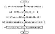
この蛍光検出装置の動作について図2及び図3を用いて説明する。この蛍光検出装置は、図2(A)に示されているように光学ユニット12が所定のウエル40の位置へ移動して検体3aの測定を行なう検体測定工程と、(B)に示されているように光学ユニット12が基準物質配置部42の位置へ移動して検体測定工程と同じ温度条件下で基準物質3bの測定を行なう補正要素測定工程を実行する。なお、この実施例では、基準温度T0時における基準物質3bの測定値IA(T0),IB(T0)は予め測定されて装置内部の記録媒体(補正要素保持部)に記憶されている。検体測定工程と補正要素測定工程はどちらを先に実行してもよいが、この例では検体測定工程を先に行なう場合について説明する。The operation of this fluorescence detection apparatus will be described with reference to FIGS. As shown in FIG. 2A, this fluorescence detection apparatus is shown in FIG. 2B, in which the
まず、測定対象の検体3aが収容されたウエル40上の位置にレンズ28がくる位置に光学ユニット12を移動させる(ステップS1)。LED14を点灯させて測定励起光を検体3aに照射し励起した検体3aからの蛍光強度I(T)を光検出器4で測定する(ステップS2)。次に、基準物質3b上にレンズ28がくる位置に光学ユニット12を移動させる(ステップS3)。 First, the
I(T)の測定と同じ温度で、LED14を点灯させて測定励起光を基準物質3bに照射して得られる検出器4の信号強度IB(T)及びLED16を点灯させて参照励起光を基準物質3bに照射して得られる検出器4の信号強度IA(T)を検出器4で測定する(ステップS4)。IA(T0),IB(T0),IA(T),IB(T)に基づいてI(T)からLED14の発光強度の温度特性の影響を除去した補正値I'(T)を求める(ステップS5)。At the same temperature as the measurement of I (T), the
なお、同じ温度で複数の検体3aについて測定を行なう場合には、その温度下で測定した補正要素IA(T),IB(T)を複数の検体3aの測定値の補正に用いることができるため、補正要素IA(T),IB(T)を検体3aごとに行なう必要はない。When measurement is performed on a plurality of
2a 参照光源装置
2b 測定光源装置
3a 検体
3b 基準物質
4 検出器
5 制御部
6 検体測定手段
7 補正要素測定手段
8 補正要素保持部
9 演算処理部
12 光学ユニット
14,16 LED
18,22,28,32 レンズ
20,26 ダイクロイックミラー
24,30 2バンドフィルタ
40 検体ウエル
42 基準物質配置部2a Reference
18, 22, 28, 32
Claims (3)
Translated fromJapanese前記基準物質に対し、基準温度T0の条件下で基準時に参照励起光を照射したときの蛍光強度IA(T0)及び基準温度T0の条件下で基準時に測定励起光を照射したときの蛍光強度IB(T0)を測定する基準時補正要素測定工程と、
測定対象の検体に対し、測定温度Tの条件下で測定時に測定励起光を照射したときの前記検体からの蛍光強度I(T)を測定する検体測定工程と、
前記基準物質に対し、測定温度Tの条件下で測定時に参照励起光を照射したときの前記基準物質からの前記蛍光強度IA(T)及び測定励起光を照射したときの前記基準物質からの蛍光強度IB(T)を測定する測定時補正要素測定工程と、
次式により得られるI'(T)に基づいて測定対象物の濃度を求める演算処理工程と、を備えた蛍光測定方法。
I'(T)=I(T)・IA(T)/IB(T)・IB(T0)/IA(T0)A reference light source that generates reference excitation light and its emission intensity can be regarded as constant regardless of temperature in the measurement temperature range, and generates measurement excitation light having a wavelength different from that of the reference excitation light, and the temperature characteristics of the emission intensity The measurement light source and the analyte to be measured are provided separately, and are excited by each of the reference excitation light and the measurement excitation light to generate fluorescence, and the temperature characteristics of the emission efficiency affect the difference in the wavelength of the excitation light. A reference material that is not
Relative to the reference material, when irradiated with measurement excitation lightto the reference time under the conditions of the fluorescence intensity IA (T0) and the reference temperature T0 at the time of irradiation with the reference excitation lightto the reference time under the conditions of the reference temperature T0 Areference time correction element measuring step for measuring the fluorescence intensity IB (T0 ) of
A sample measurement step of measuring the fluorescence intensity I (T) from the sample when the measurement target is irradiated with measurement excitation lightat the measurement temperature T under the condition of the measurement temperature T;
The fluorescence intensity IA (T) from the reference material when the reference material is irradiated with reference excitation lightat the time ofmeasurement under the condition of the measurement temperature T and the reference material from the reference material when the measurement excitation light is irradiated. Ameasurement-time correction element measurement step for measuring the fluorescence intensity IB (T);
And a calculation processing step for obtaining a concentration of the measurement object based on I ′ (T) obtained by the following equation.
I ′ (T) = I (T) · IA (T) / IB (T) · IB (T0 ) / IA (T0 )
参照励起光とは異なる波長をもつ測定励起光を発生させその発光強度に温度特性を有する測定光源と、
検体を配置するための検体配置部と、
前記参照励起光と測定励起光のそれぞれにより励起されて蛍光を発生させ、その発光効率の温度特性が励起光の波長の違いに影響されない基準物質を配置するための基準物質配置部と、
入射した光の強度を検出する光検出器と、
前記参照光源からの参照励起光を前記検体配置部又は基準物質配置部に導く参照光学系と、
前記測定光源からの測定励起光を前記検体配置部又は基準物質配置部に導く測定光学系と、
検体又は基準物質から発せられた蛍光を前記光検出器に導く蛍光光学系と、
前記参照光源、測定光源及び光検出器を制御する制御部と、
前記光検出器の信号強度に基づいて測定対象物の濃度を求める演算処理部と、
前記基準物質に対し、基準温度T0の条件下で参照励起光を照射したときの蛍光強度IA(T0)及び基準温度T0の条件下で基準時に測定励起光を照射したときの蛍光強度IB(T0)を保持する補正要素保持部と、を備え、
前記制御部は、測定対象の検体に対し、測定温度Tの条件下で測定時に測定励起光を照射したときの前記検体からの蛍光強度I(T)を測定するように構成された検体測定手段と、前記基準物質に対し、測定温度Tの条件下で測定時に参照励起光を照射したときの前記基準物質からの前記蛍光強度IA(T)及び測定励起光を照射したときの前記基準物質からの蛍光強度IB(T)を測定するように構成された測定時補正要素測定手段と、を備え、
前記演算処理部は次式により得られるI'(T)に基づいて測定対象物の濃度を求めるように構成されている蛍光検出装置。
I'(T)=I(T)・IA(T)/IB(T)・IB(T0)/IA(T0)A reference light source that generates reference excitation light and whose emission intensity can be considered constant regardless of temperature in the measurement temperature range;
A measurement light source that generates a measurement excitation light having a wavelength different from that of the reference excitation light and has a temperature characteristic in its emission intensity;
A specimen placement unit for placing the specimen;
A reference substance arranging part for arranging a reference substance that is excited by each of the reference excitation light and the measurement excitation light to generate fluorescence and whose temperature characteristics of the light emission efficiency are not affected by the difference in wavelength of the excitation light;
A photodetector for detecting the intensity of the incident light;
A reference optical system that guides reference excitation light from the reference light source to the specimen placement unit or the reference material placement unit;
A measurement optical system for guiding measurement excitation light from the measurement light source to the specimen placement unit or the reference material placement unit;
A fluorescence optical system that guides fluorescence emitted from a specimen or a reference substance to the photodetector;
A control unit for controlling the reference light source, the measurement light source, and the photodetector;
An arithmetic processing unit for determining the concentration of the measurement object based on the signal intensity of the photodetector;
Fluorescence intensity IA (T0 ) when the reference substance is irradiated with reference excitation light under the condition of the reference temperature T0 and fluorescencewhen the measurement excitation light is irradiated at thereference time under the condition of thereference temperature T0 A correction element holding unit that holds the intensity IB (T0 ),
The control unit is configured to measure a fluorescence intensity I (T) from the sample when the sample tobe measured is irradiated with measurement excitation lightat the time of measurement under the condition of the measurement temperature T. The fluorescence intensity IA (T) from the reference material when the reference material is irradiated with the reference excitation lightat the measurement temperature T under the condition of the measurement temperature T and the reference material when the measurement excitation light is irradiated Ameasurement correction element measuring means configured to measure the fluorescence intensity IB (T) from
The fluorescence detection apparatus configured to obtain the concentration of the measurement object based on I ′ (T) obtained by the following equation.
I ′ (T) = I (T) · IA (T) / IB (T) · IB (T0 ) / IA (T0 )
Priority Applications (1)
| Application Number | Priority Date | Filing Date | Title |
|---|---|---|---|
| JP2010147961AJP5370286B2 (en) | 2010-06-29 | 2010-06-29 | Fluorescence detection device |
Applications Claiming Priority (1)
| Application Number | Priority Date | Filing Date | Title |
|---|---|---|---|
| JP2010147961AJP5370286B2 (en) | 2010-06-29 | 2010-06-29 | Fluorescence detection device |
Publications (2)
| Publication Number | Publication Date |
|---|---|
| JP2012013450A JP2012013450A (en) | 2012-01-19 |
| JP5370286B2true JP5370286B2 (en) | 2013-12-18 |
Family
ID=45600083
Family Applications (1)
| Application Number | Title | Priority Date | Filing Date |
|---|---|---|---|
| JP2010147961AActiveJP5370286B2 (en) | 2010-06-29 | 2010-06-29 | Fluorescence detection device |
Country Status (1)
| Country | Link |
|---|---|
| JP (1) | JP5370286B2 (en) |
Families Citing this family (4)
| Publication number | Priority date | Publication date | Assignee | Title |
|---|---|---|---|---|
| KR20130128274A (en)* | 2012-05-16 | 2013-11-26 | 삼성테크윈 주식회사 | Optical filter assembly, optical apparatus comprising the same and method for controlling the optical apparatus |
| CN105842220A (en)* | 2016-05-26 | 2016-08-10 | 伯格森(北京)科技有限公司 | Vegetation fluorescence time sequence measuring system and method |
| CN110579598B (en)* | 2018-06-07 | 2023-12-05 | 昆明联恩生物技术有限责任公司 | Optical signal detection device, system and method |
| JP6923702B1 (en)* | 2020-04-01 | 2021-08-25 | 浜松ホトニクス株式会社 | Optical measuring device and optical measuring method |
Family Cites Families (3)
| Publication number | Priority date | Publication date | Assignee | Title |
|---|---|---|---|---|
| JPH03120445A (en)* | 1989-10-04 | 1991-05-22 | Hitachi Ltd | Automatic fluorescence measurement device |
| DE102005043834A1 (en)* | 2005-09-13 | 2007-03-22 | Eppendorf Ag | Device for performing real-time PCR reactions |
| JP2009014379A (en)* | 2007-07-02 | 2009-01-22 | Toppan Printing Co Ltd | Genetic analyzer |
- 2010
- 2010-06-29JPJP2010147961Apatent/JP5370286B2/enactiveActive
Also Published As
| Publication number | Publication date |
|---|---|
| JP2012013450A (en) | 2012-01-19 |
Similar Documents
| Publication | Publication Date | Title |
|---|---|---|
| US8699023B2 (en) | Reflectivity measuring device, reflectivity measuring method, membrane thickness measuring device, and membrane thickness measuring method | |
| EP2596332B1 (en) | Increase of usable dynamic range in photometry | |
| JP5760096B2 (en) | Systems and methods for metered dose illumination in biological analysis or other systems | |
| TWI633294B (en) | Concentration measuring device | |
| JP4418731B2 (en) | Photoluminescence quantum yield measurement method and apparatus used therefor | |
| US20070070345A1 (en) | Light amount measuring apparatus and light amount measuring method | |
| JP5370286B2 (en) | Fluorescence detection device | |
| KR101533588B1 (en) | Apparatus and method for inspecting defect of light emitting diode | |
| CN106066308A (en) | Optical analyzer | |
| CN101273262A (en) | Apparatus for performing real-time PCR reactions | |
| KR20130113072A (en) | Apparatus for measuring absorbance using cmos image sensor | |
| JP2015127703A5 (en) | ||
| RU2015132842A (en) | METHOD AND DEVICE FOR DETERMINING CONCENTRATION | |
| JP2014149194A (en) | Measuring device and measuring method | |
| US20160061730A1 (en) | Fluorescence detection apparatus, test substance detection apparatus, and fluorescence detection method | |
| CN105738283A (en) | Optical analyzer | |
| CN105866029A (en) | Optical analyzer | |
| TW201723469A (en) | Optical measuring device | |
| US10677734B2 (en) | Method and apparatus for optical measurement of liquid sample | |
| JP5732337B2 (en) | Phosphorescence measurement method | |
| JP2012515909A (en) | Sample optical measuring apparatus and optical measuring method | |
| JP5002980B2 (en) | Rice quality measuring method and rice quality measuring device | |
| US9006685B2 (en) | Device and method for determining the concentration of fluorophores in a sample | |
| JP5760589B2 (en) | Method and apparatus for measuring fluorescence spectrum of phosphor for white LED device | |
| JP2014142299A (en) | Gas concentration measurement device |
Legal Events
| Date | Code | Title | Description |
|---|---|---|---|
| A621 | Written request for application examination | Free format text:JAPANESE INTERMEDIATE CODE: A621 Effective date:20121022 | |
| A977 | Report on retrieval | Free format text:JAPANESE INTERMEDIATE CODE: A971007 Effective date:20130517 | |
| A131 | Notification of reasons for refusal | Free format text:JAPANESE INTERMEDIATE CODE: A131 Effective date:20130528 | |
| A521 | Written amendment | Free format text:JAPANESE INTERMEDIATE CODE: A523 Effective date:20130729 | |
| TRDD | Decision of grant or rejection written | ||
| A01 | Written decision to grant a patent or to grant a registration (utility model) | Free format text:JAPANESE INTERMEDIATE CODE: A01 Effective date:20130820 | |
| A61 | First payment of annual fees (during grant procedure) | Free format text:JAPANESE INTERMEDIATE CODE: A61 Effective date:20130902 | |
| R151 | Written notification of patent or utility model registration | Ref document number:5370286 Country of ref document:JP Free format text:JAPANESE INTERMEDIATE CODE: R151 |