JP5366555B2 - System and method for pressure compensation in a pump - Google Patents
System and method for pressure compensation in a pumpDownload PDFInfo
- Publication number
- JP5366555B2 JP5366555B2JP2008543354AJP2008543354AJP5366555B2JP 5366555 B2JP5366555 B2JP 5366555B2JP 2008543354 AJP2008543354 AJP 2008543354AJP 2008543354 AJP2008543354 AJP 2008543354AJP 5366555 B2JP5366555 B2JP 5366555B2
- Authority
- JP
- Japan
- Prior art keywords
- pressure
- dispensing
- chamber
- pump
- valve
- Prior art date
- Legal status (The legal status is an assumption and is not a legal conclusion. Google has not performed a legal analysis and makes no representation as to the accuracy of the status listed.)
- Active
Links
- 238000000034methodMethods0.000titleclaimsabstractdescription53
- 238000005086pumpingMethods0.000claimsabstractdescription11
- 239000007788liquidSubstances0.000claimsdescription25
- 230000008569processEffects0.000claimsdescription20
- 238000012937correctionMethods0.000claimsdescription5
- 238000007789sealingMethods0.000claimsdescription3
- 238000003860storageMethods0.000claimsdescription3
- 238000005070samplingMethods0.000claims1
- 239000012530fluidSubstances0.000abstractdescription154
- 230000001105regulatory effectEffects0.000abstract1
- 238000010926purgeMethods0.000description80
- 238000010586diagramMethods0.000description22
- 238000002955isolationMethods0.000description21
- 238000011049fillingMethods0.000description20
- 238000004458analytical methodMethods0.000description16
- 238000001914filtrationMethods0.000description16
- 230000000875corresponding effectEffects0.000description15
- 230000003068static effectEffects0.000description13
- 230000000694effectsEffects0.000description12
- 238000009530blood pressure measurementMethods0.000description11
- 230000008901benefitEffects0.000description10
- 230000001965increasing effectEffects0.000description10
- 239000000463materialSubstances0.000description9
- 235000012431wafersNutrition0.000description9
- 230000007246mechanismEffects0.000description7
- 239000004810polytetrafluoroethyleneSubstances0.000description7
- 229920001343polytetrafluoroethylenePolymers0.000description7
- 230000008859changeEffects0.000description6
- 230000006870functionEffects0.000description6
- 239000000126substanceSubstances0.000description6
- 230000002411adverseEffects0.000description5
- 230000007423decreaseEffects0.000description5
- 238000011045prefiltrationMethods0.000description5
- 239000004065semiconductorSubstances0.000description5
- 238000007792additionMethods0.000description4
- 238000004891communicationMethods0.000description4
- 229910052751metalInorganic materials0.000description4
- 239000002184metalSubstances0.000description4
- 238000012986modificationMethods0.000description4
- 230000004048modificationEffects0.000description4
- 229920000642polymerPolymers0.000description4
- 230000002829reductive effectEffects0.000description4
- 230000002441reversible effectEffects0.000description4
- 230000000630rising effectEffects0.000description4
- 230000009471actionEffects0.000description3
- 239000000284extractSubstances0.000description3
- 238000004519manufacturing processMethods0.000description3
- 238000012544monitoring processMethods0.000description3
- 239000004698PolyethyleneSubstances0.000description2
- -1polyethylenePolymers0.000description2
- 229920000573polyethylenePolymers0.000description2
- 238000003825pressingMethods0.000description2
- 238000012545processingMethods0.000description2
- 230000008707rearrangementEffects0.000description2
- 238000006467substitution reactionMethods0.000description2
- 230000007704transitionEffects0.000description2
- 239000004963TorlonSubstances0.000description1
- 229920003997Torlon®Polymers0.000description1
- 230000002745absorbentEffects0.000description1
- 239000002250absorbentSubstances0.000description1
- 238000010521absorption reactionMethods0.000description1
- 229910052782aluminiumInorganic materials0.000description1
- XAGFODPZIPBFFR-UHFFFAOYSA-NaluminiumChemical compound[Al]XAGFODPZIPBFFR-UHFFFAOYSA-N0.000description1
- 230000009286beneficial effectEffects0.000description1
- 239000000919ceramicSubstances0.000description1
- 239000003795chemical substances by applicationSubstances0.000description1
- 210000000078clawAnatomy0.000description1
- 238000000576coating methodMethods0.000description1
- 230000001276controlling effectEffects0.000description1
- 230000002596correlated effectEffects0.000description1
- 230000008878couplingEffects0.000description1
- 238000010168coupling processMethods0.000description1
- 238000005859coupling reactionMethods0.000description1
- 230000001934delayEffects0.000description1
- 230000003111delayed effectEffects0.000description1
- 238000013461designMethods0.000description1
- 230000001627detrimental effectEffects0.000description1
- 238000007599dischargingMethods0.000description1
- 238000005516engineering processMethods0.000description1
- 238000000605extractionMethods0.000description1
- 238000000671immersion lithographyMethods0.000description1
- 239000012535impuritySubstances0.000description1
- 230000001939inductive effectEffects0.000description1
- 230000014759maintenance of locationEffects0.000description1
- 230000003287optical effectEffects0.000description1
- 229920005548perfluoropolymerPolymers0.000description1
- 230000002093peripheral effectEffects0.000description1
- 229920002120photoresistant polymerPolymers0.000description1
- 238000002360preparation methodMethods0.000description1
- 230000009467reductionEffects0.000description1
- 230000004044responseEffects0.000description1
- 230000000717retained effectEffects0.000description1
- 230000011218segmentationEffects0.000description1
- 238000012163sequencing techniqueMethods0.000description1
- 238000004544sputter depositionMethods0.000description1
- 229910001220stainless steelInorganic materials0.000description1
- 239000010935stainless steelSubstances0.000description1
- 239000000758substrateSubstances0.000description1
- 230000001360synchronised effectEffects0.000description1
- 239000002699waste materialSubstances0.000description1
- XLYOFNOQVPJJNP-UHFFFAOYSA-NwaterSubstancesOXLYOFNOQVPJJNP-UHFFFAOYSA-N0.000description1
Images


Classifications
- F—MECHANICAL ENGINEERING; LIGHTING; HEATING; WEAPONS; BLASTING
- F04—POSITIVE - DISPLACEMENT MACHINES FOR LIQUIDS; PUMPS FOR LIQUIDS OR ELASTIC FLUIDS
- F04B—POSITIVE-DISPLACEMENT MACHINES FOR LIQUIDS; PUMPS
- F04B49/00—Control, e.g. of pump delivery, or pump pressure of, or safety measures for, machines, pumps, or pumping installations, not otherwise provided for, or of interest apart from, groups F04B1/00 - F04B47/00
- F04B49/08—Regulating by delivery pressure
- F—MECHANICAL ENGINEERING; LIGHTING; HEATING; WEAPONS; BLASTING
- F04—POSITIVE - DISPLACEMENT MACHINES FOR LIQUIDS; PUMPS FOR LIQUIDS OR ELASTIC FLUIDS
- F04B—POSITIVE-DISPLACEMENT MACHINES FOR LIQUIDS; PUMPS
- F04B49/00—Control, e.g. of pump delivery, or pump pressure of, or safety measures for, machines, pumps, or pumping installations, not otherwise provided for, or of interest apart from, groups F04B1/00 - F04B47/00
- F—MECHANICAL ENGINEERING; LIGHTING; HEATING; WEAPONS; BLASTING
- F04—POSITIVE - DISPLACEMENT MACHINES FOR LIQUIDS; PUMPS FOR LIQUIDS OR ELASTIC FLUIDS
- F04B—POSITIVE-DISPLACEMENT MACHINES FOR LIQUIDS; PUMPS
- F04B13/00—Pumps specially modified to deliver fixed or variable measured quantities
- F—MECHANICAL ENGINEERING; LIGHTING; HEATING; WEAPONS; BLASTING
- F04—POSITIVE - DISPLACEMENT MACHINES FOR LIQUIDS; PUMPS FOR LIQUIDS OR ELASTIC FLUIDS
- F04B—POSITIVE-DISPLACEMENT MACHINES FOR LIQUIDS; PUMPS
- F04B49/00—Control, e.g. of pump delivery, or pump pressure of, or safety measures for, machines, pumps, or pumping installations, not otherwise provided for, or of interest apart from, groups F04B1/00 - F04B47/00
- F04B49/06—Control using electricity
- F04B49/065—Control using electricity and making use of computers
- F—MECHANICAL ENGINEERING; LIGHTING; HEATING; WEAPONS; BLASTING
- F04—POSITIVE - DISPLACEMENT MACHINES FOR LIQUIDS; PUMPS FOR LIQUIDS OR ELASTIC FLUIDS
- F04B—POSITIVE-DISPLACEMENT MACHINES FOR LIQUIDS; PUMPS
- F04B51/00—Testing machines, pumps, or pumping installations
- F—MECHANICAL ENGINEERING; LIGHTING; HEATING; WEAPONS; BLASTING
- F04—POSITIVE - DISPLACEMENT MACHINES FOR LIQUIDS; PUMPS FOR LIQUIDS OR ELASTIC FLUIDS
- F04B—POSITIVE-DISPLACEMENT MACHINES FOR LIQUIDS; PUMPS
- F04B2205/00—Fluid parameters
- F04B2205/03—Pressure in the compression chamber
Landscapes
- Engineering & Computer Science (AREA)
- Mechanical Engineering (AREA)
- General Engineering & Computer Science (AREA)
- Computer Hardware Design (AREA)
- Reciprocating Pumps (AREA)
- Control Of Positive-Displacement Pumps (AREA)
- Control Of Non-Positive-Displacement Pumps (AREA)
Abstract
Description
Translated fromJapanese (関連出願)
本願は、2005年12月2日に発明者であるGeorge GonnellaおよびJames Cedroneによって出願された、名称「System and Method for Valve Compensation in a Pump」の米国仮特許出願第60/741,682号の優先権を主張し、その全内容はすべての目的のために参照によって本願明細書に明白に援用される。(Related application)
This application is the priority of US Provisional Patent Application No. 60 / 741,682 of the name “System and Method for Valve Compensation in a Pump” filed by inventors George Gonnella and James Cedrone on December 2, 2005. All rights are hereby expressly incorporated herein by reference for all purposes.
(発明の技術分野)
本発明は、概して流体ポンプに関する。より具体的には、本発明の実施形態は、多段式ポンプに関する。さらに具体的には、本発明の実施形態は、半導体製造で使用されるポンプ内に生じ得る圧力変動の補償に関する。(Technical field of the invention)
The present invention relates generally to fluid pumps. More specifically, embodiments of the present invention relate to multi-stage pumps. More specifically, embodiments of the invention relate to compensation for pressure fluctuations that can occur in pumps used in semiconductor manufacturing.
流体がポンプ装置によって分注される量および/または速度の精密制御が必要である多くの用途が存在する。例えば、半導体プロセスでは、フォトレジスト化学物質等の光化学物質が、半導体ウエハに適用される量および速度を制御することは重要である。通常、プロセスの間に半導体ウエハに適用されるコーティングは、オングストローム単位で測定されるウエハの表面全体が平坦であることが要求される。プロセス化学物質がウエハに適用される速度は、プロセス液が均一に適用されることを確実にするために、制御されなければならない。 There are many applications where precise control of the amount and / or rate at which fluid is dispensed by the pumping device is required. For example, in semiconductor processes, it is important to control the amount and rate at which photochemicals such as photoresist chemicals are applied to a semiconductor wafer. Typically, coatings applied to semiconductor wafers during the process require that the entire surface of the wafer measured in angstroms be flat. The rate at which process chemicals are applied to the wafer must be controlled to ensure that the process liquid is applied uniformly.
今日の半導体産業で使用される多くの光化学物質は非常に高額であり、しばしば1リットル当たり1000ドルほどもかかる。したがって、最少量ではあるが適当量の化学物質を使用し、ポンプ装置によって化学物質が損傷を受けないことを確実にすることが好ましい。現在の多段式ポンプは、液体内に著しい圧力スパイクを引き起こす可能性がある。そのような圧力スパイクおよびその後の圧力低下は、流体に損傷を与えていることがある(すなわち、流体の物理的特徴を不利に変化させることがある)。さらに、圧力スパイクは、分注ポンプに意図した流体より多く分注させるか、または不利な力学を有する方法で流体を分注させる流体圧力の増加の原因となる可能性がある。 Many photochemicals used in the semiconductor industry today are very expensive and often cost as much as $ 1000 per liter. Therefore, it is preferable to use a minimum but adequate amount of chemical and to ensure that the chemical is not damaged by the pumping device. Current multistage pumps can cause significant pressure spikes in the liquid. Such pressure spikes and subsequent pressure drops may damage the fluid (i.e., adversely change the physical characteristics of the fluid). Furthermore, pressure spikes can cause the dispense pump to dispense more than the intended fluid or cause an increase in fluid pressure that causes fluid to be dispensed in a manner that has adverse mechanics.
より具体的には、封入空間がポンプ装置内に生成されると、圧力変動(閉鎖空間内の最初の圧力に対する)が、ポンプ装置の種々の構成要素の構造等の種々の理由で生じ得る。この圧力変動は、分注待機中の流体を含む分注チャンバ内で生じる場合、特に有害となり得る。このように、ポンプ装置内の圧力変動を補償するための方法が望まれる。 More specifically, when an enclosed space is created in the pump device, pressure fluctuations (relative to the initial pressure in the enclosed space) can occur for a variety of reasons, such as the structure of the various components of the pump device. This pressure fluctuation can be particularly detrimental if it occurs in a dispensing chamber containing fluid waiting to be dispensed. Thus, a method for compensating for pressure fluctuations in the pump device is desired.
ポンプ装置のチャンバ内の基準圧力を実質的に維持するためのシステムおよび方法が開示される。本発明の実施形態は、ポンプ装置のチャンバ内で生じ得る圧力変動を補償または考慮するために、モータを制御するように機能してもよい。より具体的には、分注モータは、分注チャンバ内で感知された圧力に基づく分注前に、分注チャンバ内の基準圧力を実質的に維持するよう制御されてもよい。一実施形態では、分注が開始される前に、制御ループを利用して、分注チャンバ内の圧力が所望の圧力(例えば、その前後)であるか否かを繰り返し判断し、その場合、ポンプ手段の動きは、流体の分注が開始されるまで、分注チャンバ内の所望の圧力を実質的に維持するよう調整されるようにしてもよい。 Disclosed are systems and methods for substantially maintaining a reference pressure within a chamber of a pump device. Embodiments of the present invention may function to control the motor to compensate or account for pressure fluctuations that may occur in the chamber of the pump device. More specifically, the dispensing motor may be controlled to substantially maintain a reference pressure in the dispensing chamber prior to dispensing based on the pressure sensed in the dispensing chamber. In one embodiment, before dispensing begins, the control loop is utilized to repeatedly determine whether the pressure in the dispensing chamber is the desired pressure (eg, before and after), The movement of the pump means may be adjusted to substantially maintain the desired pressure in the dispensing chamber until fluid dispensing is initiated.
本発明の実施形態は、以前に開発されたポンプシステムおよび方法の不利な点を実質的に排除または軽減する、圧力変動を補償するためのシステムおよび方法を提供する。より具体的には、本発明の実施形態は、多段式ポンプの停止時、または事実上任意の他の時間に、多段式ポンプの分注サイクルの準備完了区分内で生じ得る圧力変動を補償するためのシステムおよび方法を提供する。準備完了区分開始後、多段式ポンプの分注チャンバ内の圧力は監視され、検出された圧力変動(例えば、上昇または低下)は、分注段ダイヤフラムを動かすことによって補償されてもよい。1つの特定の実施形態では、閉ループ制御システムによって、準備完了区分の間、分注チャンバ内の圧力を監視してもよい。所望の基準圧力を上回る圧力が検出される場合、閉ループ制御システムは、分注モータに信号を送信し、単一モータのインクリメント分だけ反転させてもよい。このように、準備完了区分の間生じた圧力上昇は、分注に望ましい基準圧力に補償され、実質的に維持されてもよい。 Embodiments of the present invention provide systems and methods for compensating pressure fluctuations that substantially eliminate or reduce the disadvantages of previously developed pump systems and methods. More specifically, embodiments of the present invention compensate for pressure fluctuations that may occur within the ready section of a multi-stage pump dispense cycle when the multi-stage pump is stopped or at virtually any other time. Systems and methods are provided. After the start of the ready section, the pressure in the dispensing chamber of the multi-stage pump may be monitored and detected pressure fluctuations (eg, rising or falling) may be compensated by moving the dispensing stage diaphragm. In one particular embodiment, a closed loop control system may monitor the pressure in the dispensing chamber during the ready segment. If a pressure above the desired reference pressure is detected, the closed loop control system may send a signal to the dispense motor and invert by a single motor increment. In this way, the pressure increase that occurs during the ready segment may be compensated for and substantially maintained at the desired reference pressure for dispensing.
本発明の実施形態は、準備完了区分の長さにかかわらず、準備完了区分の間、分注チャンバ内で所望の圧力を実質的に維持させることによって、利点を提供する。 Embodiments of the present invention provide an advantage by substantially maintaining the desired pressure in the dispensing chamber during the ready section, regardless of the length of the ready section.
本発明の別の実施形態は、正確な分注および分注区分間の分注の再現性を可能にする利点を提供する。 Another embodiment of the present invention provides the advantage of allowing precise dispensing and reproducibility of dispensing between dispensing segments.
本発明のさらに別の実施形態は、正確かつ繰り返し可能な分注が可能となるため、プロセスレシピの重複(例えば、異なる基準圧力を有するシステムとともに)を可能にする利点を提供する。 Yet another embodiment of the present invention provides the advantage of allowing process recipe duplication (eg, with systems having different reference pressures) as it allows for accurate and repeatable dispensing.
本発明の別の実施形態は、分注区分の間の許容可能な流体力学を達成する利点を提供する。 Another embodiment of the present invention provides the advantage of achieving acceptable fluid dynamics during the dispensing segment.
これらの側面および本発明の他の側面は、以下の説明および添付図面と併せて考察されるとき、より明確に真価が認められ、理解されるであろう。以下の説明は、本発明の種々の実施形態およびその多数の特定の細部を表示すると同時に、例証として提供されるが、限定するものではない。多くの代用形態、修正形態、追加形態または再配置形態は、本発明の範囲内で製作してもよく、本発明には、そのような代用形態、修正形態、追加形態または再配置形態のすべてが含まれる。 These aspects and other aspects of the invention will be more clearly appreciated and understood when considered in conjunction with the following description and the accompanying drawings. The following description, while displaying various embodiments of the invention and numerous specific details thereof, is provided by way of illustration and not limitation. Many substitutions, modifications, additions or rearrangements may be made within the scope of the present invention, and the invention includes all such substitutions, modifications, additions or rearrangements. Is included.
本発明およびその利点のより完全な理解は、同様の参照番号が同様の特性を示す添付の図面と併せて、以下の説明を参照することによって得られうる。 A more complete understanding of the present invention and the advantages thereof may be obtained by reference to the following description, taken in conjunction with the accompanying drawings, in which like reference numerals indicate like characteristics.
好ましい本発明の実施形態を図に例示し、同様の数表示は、種々の図面の同様の、および対応する部分を言及するために使用されている。 Preferred embodiments of the invention are illustrated in the figures, and like numerals are used to refer to like and corresponding parts of the various drawings.
本発明の実施形態は、ポンプを使用して、流体を正確に分注するポンプシステムに関し、単段ポンプまたは多段(「多段式」)ポンプであってもよい。より具体的には、本発明の実施形態は、多段式ポンプの分注サイクルの準備完了区分に生じ得る圧力変動を補償するためのシステムおよび方法を提供する(例えば、弁が閉鎖され、分注チャンバ内等に封入空間が生成されるため)。準備完了区分開始後、多段式ポンプの分注チャンバ内の圧力は監視され、検出された圧力変動は、分注段階ダイヤフラムを動かすことによって補償されてもよい。そのようなポンプシステムの実施形態は、発明者James Cedrone、George Gonnella、およびIraj Gashgaeeが2005年12月5日に出願した米国仮特許出願第60/742,435号に開示されており、参照により全体として本願明細書に援用される。 Embodiments of the present invention relate to a pump system that uses a pump to accurately dispense fluid, and may be a single-stage pump or a multi-stage ("multi-stage") pump. More specifically, embodiments of the present invention provide systems and methods for compensating for pressure fluctuations that may occur in the ready section of a multi-stage pump dispense cycle (eg, a valve is closed and dispensed). This is because an enclosed space is generated in the chamber or the like). After the start of the ready section, the pressure in the dispensing chamber of the multi-stage pump may be monitored and detected pressure fluctuations may be compensated by moving the dispensing stage diaphragm. An embodiment of such a pump system is disclosed in U.S. Provisional Patent Application No. 60 / 742,435, filed Dec. 5, 2005, by inventors James Cedrone, George Gonella, and Iraj Gashgaee, by reference. This is incorporated herein in its entirety.
図1は、ポンプシステム10のそのような一実施形態の図である。ポンプシステム10は、流体源15と、ポンプ制御装置20と、多段式ポンプ100とを含み、ウエハ25上へ流体を分注するために恊働することができる。多段式ポンプ100の動作は、多段式ポンプ100に内蔵される、または制御信号、データもしくは他の情報を通信するための1つ以上の通信リンクを介して、多段式ポンプ100に接続されることが可能なポンプ制御装置20によって制御することができる。さらに、ポンプ制御装置20の機能性は、内蔵制御装置と別の制御装置とに分散するができる。ポンプ制御装置20は、多段式ポンプ100の動作を制御するための制御命令30一式を包含するコンピュータ読み取り可能の媒体27(例えば、RAM、ROM、フラッシュメモリ、光ディスク、磁気ドライブまたは他のコンピュータ読み取り可能の媒体)を含むことができる。プロセッサ35(例えば、CPU、ASIC、RISC、DSPまたは他のプロセッサ)は、命令を実行することができる。プロセッサの一例は、Texas Instruments TMS320F2812PGFA 16−bit DSP(Texas Instrumentsは、テキサス州ダラスを本拠地とする企業である)である。図1の実施形態では、制御装置20は、通信リンク40および45を介して多段式ポンプ100と通信する。通信リンク40および45は、ネットワーク(例えば、Ethernet(登録商標)、無線ネットワーク、グローバルエリアネットワーク、DeviceNetネットワークまたは当技術分野で既知または開発された他のネットワーク)、バス(例えば、SCSIバス)または他の通信リンクであってもよい。制御装置20は、内蔵PCB基板として、遠隔制御装置として、または他の適切な方法で実装することができる。ポンプ制御装置20は、多段式ポンプ100と通信するための制御装置への適切なインターフェース(例えば、ネットワークインターフェース、入出力インターフェース、アナログデジタル変換器および他の構成要素)を含むことができる。さらに、ポンプ制御装置20は、プロセッサ、記憶装置、インターフェース、表示デバイス、周辺機器、または簡単にするために示さないが他のコンピュータ構成要素を含み、当技術分野で既知の種々のコンピュータ構成要素を含むことができる。ポンプ制御装置20は、多段式ポンプで種々の弁およびモータを制御することができ、多段式ポンプに、低粘性流体(すなわち、100センチポアズ未満)または他の流体を含む流体を正確に分注させる。「I/O Interface System and Method for a Pump」の名称でCedroneらが2005年12月2日に出願した米国特許出願第60/741,657号、および米国特許出願第______号、「I/O Systems,Methods And Devices For Interfacing A Pump Controller」の名称で発明者Cedroneらが______に出願した[ENTG1810−1](参照によって本願明細書に全体として援用される)に記載のような入出力インターフェースコネクタは、ポンプ制御装置20を種々のインターフェースおよび製造ツールに接続するために使用することができる。 FIG. 1 is a diagram of one such embodiment of a
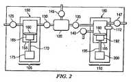
図2は、多段式ポンプ100の図である。多段式ポンプ100には、供給段階部分105および別個の分注段階部分110が含まれる。不純物をプロセス流体から濾過するために、流体の流れの観点から、フィルタ120は、供給段階部分105と分注段階部分110との間に位置する。例えば、入口弁125、隔離弁130、遮断弁135、パージ弁140、排出弁145、および出口弁147を含む、多数の弁によって、多段式ポンプ100を通る流体の流れを制御することができる。分注段階部分110は、分注段階110で流体圧力を測定することができる圧力センサ112をさらに含むことができる。圧力センサ112によって測定された圧力は、以下に記載するように種々のポンプの速度を制御するために使用することができる。圧力センサの例には、Metallux AG、Korb、Germany製のものを含み、セラミックおよびポリマーのピエゾ抵抗および容量性圧力センサが含まれる。一実施形態によると、プロセス流体に接する圧力センサ112の面は、ペルフルオロポリマーである。ポンプ100は、供給チャンバ155内の圧力を読み取るための圧力センサ等、さらなる圧力センサを含むことができる。 FIG. 2 is a diagram of a
供給段階105および分注段階110は、多段式ポンプ100内の流体をポンプで汲み上げるために、回転ダイヤフラムポンプを含むことができる。供給段階ポンプ150(「供給ポンプ150」)は、例えば、流体を回収するための供給チャンバ155と、供給チャンバ155内で動き、流体を分注するための供給段階ダイヤフラム160と、供給段階ダイヤフラム160を動かすピストン165と、送りネジ170と、ステッピングモータ175とを含む。送りネジ170は、ナット、ギア、またはモータから送りネジ170へエネルギを伝えるための他の機構を通してステッピングモータ175に結合する。一実施形態によると、供給モータ170はナットを回転させ、それによって、送りネジ170は回転させられ、ピストン165を作動させる。同様に、分注段階ポンプ180(「分注ポンプ180」)は、分注チャンバ185と、分注段階ダイヤフラム190と、ピストン192と、送りネジ195と、分注モータ200とを含むことができる。分注モータ200は、ネジ式ナット(例えば、Torlonまたは他の材料のナット)を介して、送りネジ195を駆動することができる。
他の実施形態によると、供給段階105および分注段階110は、空気圧または液圧によって作動するポンプ、液圧ポンプまたは他のポンプを含む、種々の他のポンプであってもよい。供給段階用の空気圧によって作動するポンプ、およびステッピングモータ駆動の液圧ポンプを使用した多段式ポンプの一例は、参照することによって本明細書に組み込まれる、「Pump Controller For Precision Pumping Apparatus」の名称で、発明者Zagarsらが2005年2月4日に出願した米国特許出願第11/051,576号に記載されている。しかしながら、両方の段階でモータを使用することは、液圧パイプ、制御システムおよび流体が除去され、それによって空間および潜在的漏洩を減少させるという利点を提供する。 According to other embodiments,
供給モータ175および分注モータ200は、任意の適切なモータであってもよい。一実施形態によると、分注モータ200は、永久磁石同期モータ(「PMSM」)である。PMSMは、モータ200、多段式ポンプ100内蔵の制御装置、または別個のポンプ制御装置(例えば、図1に示すような)で、ベクトル制御(「FOC」)または当技術分野で既知の他の型の位置/速度制御部を利用するデジタルシグナルプロセッサ(「DSP」)によって制御することができる。さらに、PMSM 200は、分注モータ200の位置の即時フィードバックのためのエンコーダ(例えば、細線回転式位置エンコーダ)をさらに含むことが可能である。位置センサを使用すると、ピストン192の位置の正確で反復可能な制御が得られ、ひいては分注チャンバ185内での流体運動に正確で反復可能な制御をもたらす。例えば、一実施形態に従い、DSPに8000パルスをもたらす2000ラインエンコーダを使用して、0.045度の回転で正確に測定し、制御することが可能となる。さらに、PMSMは、振動がほとんどまたは全くない状態の低速で駆動することができる。さらに、供給モータ175は、PMSMまたはステッピングモータであってもよい。さらに、供給ポンプは、供給ポンプが定位置にある場合に表示する定位置センサを含むことができることに留意すべきである。
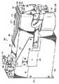
図3Aは、多段式ポンプ100のためのポンプアセンブリの一実施形態の図である。多段式ポンプ100は、多段式ポンプ100を通して種々の流体流路を画定し、また供給チャンバ155および分注チャンバ185を少なくとも部分的に画定する分注ブロック205を含むことができる。一実施形態による、分注ポンプブロック205は、PTFE、修飾PTFEまたは他の材料から成る単一ブロックであってもよい。これらの材料は、多くのプロセス流体と反応しない、または反応性が少ないので、これらの材料を使用すると、流通路およびポンプチャンバは、最低限のハードウェアの追加をもって分注ブロック205に直接機械加工することができる。ひいては、分注ブロック205は、一体型流体マニホールドを提供することによって、パイピングの必要性を軽減する。 FIG. 3A is a diagram of one embodiment of a pump assembly for
分注ブロック205は、例えば、流体を受ける入口210、流体をパージ/排出するためのパージ/排出出口215、および流体が分注区分の間に分注される分注出口220を含み、種々の外部入口および外部出口を含むことができる。図3Aの例では、パージされた流体は、供給チャンバに送り戻されるので(図4Aおよび図4Bに示す)、分注ブロック205は、外部パージ出口を含まない。しかしながら、他の本発明の実施形態では、流体は、外部からパージすることができる。参照によって本明細書に全体として援用される、「O−RING−LESS LOW PROFILE FITTING AND ASSEMBLY THEREOF」の名称で、Iraj Gashgaeeが2005年12月2日に出願した米国仮特許出願第60/741,667号は、分注ブロック205の外部入口および外部出口を流体管路に接続するために利用することができる取付部品の実施形態を記載している。
分注ブロック205は、供給ポンプと、分注ポンプと、フィルタ120とへ流体を送る。ポンプカバー225は、供給モータ175および分注モータ200を損傷から保護することができるが、ピストンハウジング227は、ピストン165およびピストン192を保護することができ、本発明の一実施形態によると、ポリエチレンまたは他のポリマーから形成することができる。弁板230は、流体の流れを多段式ポンプ100の種々の構成要素に誘導するように構成することができる弁(例えば、図2の入口弁125、隔離弁130、遮断弁135、パージ弁140、および排出弁145)のための弁ハウジングを提供する。一実施形態によると、入口弁125、隔離弁130、遮断弁135、パージ弁140、および排出弁145のそれぞれは、弁板230に少なくとも部分的に統合され、対応するダイヤフラム圧力または真空を印加するか否かに応じて開状態または閉状態となるダイヤフラム弁である。他の実施形態では、弁のいくつかのは、分注ブロック205の外部にあってもよく、またはさらなる弁板に配置してもよい。一実施形態によると、1枚のPTFEは、弁板230と分注ブロック205との間に挟入され、種々の弁のダイヤフラムを形成する。弁板230は、それぞれの弁のための弁制御入口を含み、対応するダイヤフラムに圧力または真空を印加する。例えば、入口235は、遮断弁135に、入口240はパージ弁140、入口245は隔離弁130、入口250は排出弁145、入口255は入口弁125に対応する(この場合、出口弁147は、外部)。圧力または真空を入口に選択的に印加することによって、対応する弁は、開状態および閉状態となる。
弁制御ガスおよび真空は、弁制御マニホールド(上蓋263またはハウジングカバー225の真下の領域の中の)から分注ブロック205を通って弁板230へ達する、弁制御供給管路260を介して弁板230に提供される。弁制御ガス供給入口265は、加圧ガスを弁制御マニホールドに提供し、真空入口270は、真空(または低圧力)を弁制御マニホールドに提供する。弁制御マニホールドは、対応する弁を作動させるために、供給管路260を介して弁板230の適切な入口に加圧ガスまたは真空を送る三方弁の役割をする。一実施形態では、「Fixed Volume Valve System」の名称でGashgaeeらが________に出願した米国特許出願第____[ENTG1770−1](参照することによって本明細書に全体として組み込まれる)に記載のような弁板は、弁の保持量を減少し、真空ゆらぎに起因する量の変動を除去し、真空必要条件を緩和し、また弁ダイヤフラムの応力を減少するために使用することができる。 The valve control gas and vacuum are passed through the valve
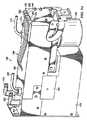
図3Bは、多段式ポンプ100の他の実施形態の図である。図3Bに示す特性の多くは、上記の図3Aとともに記載したものと類似している。しかしながら、図3Bの実施形態は、流体液滴が、電子機器を収納する多段式ポンプ100の領域に入らないようにするいくつかの特性を含む。流体液滴は、例えば、操作者が管を入口210、出口215または排出220に接続または切断する場合に発生する可能がある。「防滴」の特性は、潜在的に有害な化学物質の液滴がポンプ、特に電子チャンバに入らないように設計されており、必ずしもポンプが「耐水性」であることを要求しない(例えば、漏洩のない流体中の潜水艇)。他の実施形態によると、ポンプは完全に密閉することができる。 FIG. 3B is a diagram of another embodiment of a
一実施形態によると、分注ブロック205は、垂直に突出しているフランジ、または上蓋263と接する分注ブロック205の端縁部から外側に突出しているリップ272を含むことができる。上端縁部では、一実施形態によると、上蓋263の上部は、リップ272の上表面と同一平面上にある。これにより、分注ブロック205および上蓋263の上部接合部分付近の液滴は、接合部分を通過するよりはむしろ分注ブロック205上に達する傾向になる。しかしながら、側面では、上蓋263は、リップ272の基部と同一平面上にあるか、さもなければリップ272の外部表面から内部にオフセットする。これにより、液滴は、上蓋263と分注ブロック205の間よりはむしろ上蓋263およびリップ272によってできる角に流れ落ちる傾向になる。さらに、ゴム製密閉部は、上蓋263の上端縁部と裏板271との間に設置され、液滴が上蓋263と裏板271との間に漏れることを阻止する。 According to one embodiment, the dispensing
さらに、分注ブロック205は、電子機器を収納するポンプ100の領域から離れるように下方に傾斜する分注ブロック205内で画定される傾斜表面を含む傾斜特性273を含むことができる。その結果として、分注ブロック205の上部付近の液滴は、電子機器から離れるように導かれる。さらに、ポンプカバー225はまた、分注ブロック205の外部側端縁部から若干内側にオフセットすることができるので、ポンプ100の側部の液滴は、ポンプカバー225の接続部分およびポンプ100の他の部分を流れ過ぎる傾向にある。 In addition, the dispense
本発明の一実施形態によると、金属カバーが分注ブロック205と接合する時はいつも、金属カバーの垂直表面は、分注ブロック205の対応する垂直表面から若干内部にオフセットする(例えば、1/64インチまたは0.396875ミリメートル)。さらに、多段式ポンプ100は、密閉部、傾斜特性、または電子機器を収納する多段式ポンプ100の部分に液滴が入らないようにするための他の特性を含むことができる。さらに、図4Aに示し、以下に論じるように、裏板271は、多段式ポンプ100をさらに「防滴」する特性を含むことができる。 According to one embodiment of the invention, whenever the metal cover joins the dispensing
図4Aは、そこに画定される流体流路を示すために透明にされる分注ブロック205を有する多段式ポンプ100の一実施形態の図である。分注ブロック205は、多段式ポンプ100のための種々のチャンバおよび流体流路を画定する。一実施形態によると、供給チャンバ155および分注チャンバ185は、分注ブロック205に直接機械加工することができる。さらに、種々の流路は、分注ブロック205に機械加工することができる。流体流路275(図5Cに示す)は、入口210から入口弁に達する。流体流路280は、入口弁から供給チャンバ155へ達し、入口210から供給ポンプ150へのポンプ入口路を終了する。弁ハウジング230内の入口弁125は、入口210と供給ポンプ150との間の流れを調節する。流通路285は、弁板230内で供給ポンプ150から隔離弁130へ流体を送る。隔離弁130からの流出は、他の流通路(図示せず)によってフィルタ120へ送られる。流体は、フィルタ120から、フィルタ120を排出弁145および遮断弁135に接続する流通路を通って流れる。排出弁145からの流出は、排出出口215へ送られ、遮断弁135からの流出は、流通路290を介して分注ポンプ180へ送られる。分注ポンプは、分注区分の間では、流通路295を介して出口220へ、またはパージ区分の間では、流通路300を通ってパージ弁へ流体を流出することができる。パージ区分の間では、流体は、流通路305を通って供給ポンプ150に戻ることができる。流体流路は、PTFE(または他の材料)ブロック内に直接形成することができるので、分注ブロック205は、多段式ポンプ100の種々の部品の間のプロセス流体のためのパイピング、さらなる管類の必要性を除去または軽減する役割をすることができる。他の場合には、管類は、流体流路を画定するために、分注ブロック205に挿入することができる。図4Bは、一実施形態による、流通路のうちのいくつかを示すために透明にされた分注ブロック205の図を提供する。 FIG. 4A is an illustration of one embodiment of a
図4Aに戻ると、図4Aは、供給段階モータ190を含む供給ポンプ150と、分注モータ200を含む分注ポンプ180と、弁制御マニホールド302とを表示するためにポンプカバー225および上蓋263を外した状態の多段式ポンプ100をさらに示す。本発明の一実施形態によると、供給ポンプ150、分注ポンプ180および弁板230の一部分は、分注ブロック205内の対応する空洞に挿入される棒(例えば、金属棒)を使用して、分注ブロック205に結合することができる。それぞれの棒は、ネジを受けるための1つ以上のネジ穴を含むことができる。一例として、分注モータ200およびピストンハウジング227は、棒285内の対応する穴に螺入するために、分注ブロック205内のネジ穴を通って達する1つ以上のネジ(例えば、ネジ275およびネジ280)によって分注ブロック205に取り付けることができる。構成要素を分注ブロック205に結合するためにこの機構は、例証として提供され、任意の適切な添着機構を使用できることに留意されるべきである。 Returning to FIG. 4A, FIG. 4A shows the
本発明の一実施形態によると、裏板271は、上蓋263およびポンプカバー225が取り付けられる、内部に延在するツメ(例えば、張り出し受け274)を含むことができる。上蓋263およびポンプカバー225は、張り出し受け274に重なるので(例えば、上蓋263の下後方端縁部およびポンプカバー225の上後方端縁部で)、液滴は、上蓋263の下端縁部とポンプカバー225の上端縁部との間、または上蓋263およびポンプカバー225の後方端縁部での任意の空間の電気機器領域に流れることを阻止される。 According to one embodiment of the present invention, the
本発明の一実施形態によると、マニホールド302は、圧力/真空を弁板230に選択的に誘導するために、ソレノイド弁一式を含むことができる。特定のソレノイドを作動させ、それによって真空または圧力を弁へ誘導する場合には、実践形態にもよるが、ソレノイドは発熱する。一実施形態によると、マニホールド302は、分注ブロック205、特に分注チャンバ185から離れるようにPCB基板(裏板271に取り付けられ、図4Cにより明瞭に示される)の下方に取り付けられる。マニホールド302は、張り出し受けに取り付けることができ、それによって、裏板271に取り付けられるか、または裏板271に結合させることができる。これは、マニホールド302内のソレノイドからの熱が、分注ブロック205内の流体に作用しないように助ける。裏板271は、熱をマニホールド302およびPCBから分散することができる、ステンレス鋼機械加工のアルミニウムまたは他の材料から製作することができる。言い換えれば、裏板271は、マニホールド302およびPCBのために放熱張り出し受けの役割をすることができる。ポンプ100は、表面または熱が裏板271によって伝導することができる他の構造にさらに取り付けることができる。このようにして、裏板271およびそれが添着される構造は、マニホールド302およびポンプ100の電子機器のための放熱板の役割をする。 According to one embodiment of the invention, the manifold 302 can include a set of solenoid valves to selectively induce pressure / vacuum to the
図4Cは、弁板230へ圧力または真空を印加するための供給管路260を示す多段式ポンプ100の図である。図3と併せて論じたように、弁板230内の弁は、流体が多段式ポンプ100の種々の構成要素に流れるように構成することができる。弁の作動は、それぞれの供給管路260に圧力か、または真空を誘導する弁制御マニホールド302によって制御される。それぞれの供給管路260は、小さな開口部を有する取付部品(取付部品の例は318に示す)を含むことができる。この開口部は、取付部品318が添着される、対応する供給管路260の直径より小さな直径から製作してもよい。一実施形態では、開口部は、直径約0.010インチであってもよい。このようにして、取付部品318の開口部は、供給管路260内に制限を設けるように役立つことがある。それぞれの供給管路260内の開口部は、供給管路へ圧力および真空を印加する間の急激な圧力差の作用を軽減するのに役立ち、ひいては、弁へ圧力および真空を印加する間の転移を円滑にする。言い換えれば、開口部は、下流弁のダイヤフラムでの圧力変化の衝撃を軽減するのに役立つ。これにより、弁は、より円滑に開閉でき、また弁の開閉によって引き起こされるシステム内でのより円滑な圧力転移をもたらし、実際に弁本体の寿命を延ばすことになる。 FIG. 4C is a diagram of the
さらに、図4Cは、マニホールド302が結合されたPCB397を例示する。本発明の一実施形態によると、マニホールド302は、PCB基板397から信号を受信することができ、ソレノイドに種々の供給管路260に真空/圧力を誘導するために開/閉させ、多段式ポンプ100の弁を制御する。この場合もやはり、図4Cに示すように、マニホールド302は、分注ブロック205からPCB397の遠位端に位置することができ、分注ブロック205内の流体への熱作用を軽減する。さらに、PCBの設計および空間的制約に基づいて実行可能な範囲まで、発熱する構成要素は、分注ブロック205から離れるようにPCBの側部に設置することができ、この場合もやはり、熱作用を軽減する。マニホールド302およびPCB397からの熱は、裏板271によって分散することができる。他方では、図4Dは、マニホールド302が分注ブロック205に直接取り付けられるポンプ100の実施形態の図である。 Further, FIG. 4C illustrates
ここで、多段式ポンプ100の動作を説明することは有用となり得る。多段式ポンプ100の作動の間、多段式ポンプ100の弁は、多段式ポンプ100の種々の部分に流体の流れを許容または制限するために開閉する。一実施形態によると、これらの弁は、圧力または真空が印加されるか否かに応じて開閉する、空気圧によって作動する(すなわち、ガスで駆動)ダイヤフラム弁であってもよい。しかしながら、他の本発明の実施形態では、任意の適切な弁を使用することができる。 Here, it can be useful to describe the operation of the
多段式ポンプ100の動作の種々の段階の要約を以下に示す。しかしながら、多段式ポンプ100は、弁および制御圧力をシーケンスするために、それぞれが参照することによって本明細書に完全に組み込まれる、「Systems And Methods For Fluid Flow Control In An Immersion Lithography System」の名称で、Michael Clarke、Robert F.McLoughlin、およびMarc Laverdiereが2006年8月11日に出願した米国特許出願第11/502,729号に記載されているものを含むが、これらに限定されるものではない種々の制御スキームにより制御することができる。一実施形態によると、多段式ポンプ100は、準備完了区分、分注区分、充填区分、前濾過区分、濾過区分、排出区分、パージ区分および静的パージ区分を含むことができる。供給区分の間には、入口弁125は開状態となり、供給段階ポンプ150は、供給段階ダイヤフラム160を動かし(例えば、引く)、流体を供給チャンバ155の中に汲み上げる。十分な量の流体が供給チャンバ155に充満されると、入口弁125は閉状態となる。濾過区分の間には、供給段階ポンプ150は供給段階ダイヤフラム160を動かし、供給チャンバ155から流体を排出する。隔離弁130および遮断弁135は開状態となり、流体はフィルタ120を通って分注チャンバ185へ流れることが可能となる。一実施形態によると、最初に隔離弁130が開状態となることができ(例えば、「前濾過区分」において)、圧力をフィルタ120内で高めることが可能となり、その後、遮断弁135が開状態となり、分注チャンバ185の中への流体の流れが可能となる。他の実施形態によると、隔離弁130および遮断弁135の両方が開状態となることができ、供給ポンプは、フィルタの分注側で圧力を高めるために動く。濾過区分の間には、分注ポンプ180は、定位置に持って来ることができる。両方とも参照することによって本明細書の組み込まれる、「System And Method For A Variable Home Position Dispense System」の名称で、Laverdiereらが2004年11月23日に出願した米国仮特許出願第60/630,384号および「System And Method For A Variable Home Position Dispense System」の名称で、Laverdiereらが2005年11月21日に出願した国際出願第PCT/US2005/042127号に記載されるように、分注ポンプの定位置は、分注サイクルに対して分注ポンプでの利用可能な最大量をもたらすが、分注ポンプが提供できる利用可能な最大限の量に満たない位置であってもよい。定位置は、多段式ポンプ100の未使用の保持量を減少するために分注サイクルに対する種々のパラメータに基づき選択される。同様に、供給ポンプ150は、利用可能な最大限の量に満たない量を提供する定位置に持って来ることができる。 A summary of the various stages of operation of the
排出区分の始まりでは、隔離弁130は開状態となり、遮断弁135は閉状態となり、また排出弁145は開状態となる。他の実施形態では、遮断弁135は、排出区分の間には開状態を維持し、排出区分の終わりで閉状態となることができる。この間に、遮断弁135が開状態である場合、圧力センサ112によって測定することができる、分注チャンバ内の圧力が、フィルタ120内の圧力によって作用されるので、圧力は、制御装置によって認識されることができる。供給段階ポンプ150は、流体に圧力を加え、フィルタ120から開状態の排出弁145を通して気泡を除去する。供給段階ポンプ150を制御し、既定の速度で排出を生じさせることができ、より長い排出時間およびより低速での排出が可能になり、それによって排出廃棄量の正確な制御が可能となる。供給ポンプが空気圧式ポンプである場合は、流体の流れの制限は、排出流体路内で行うことができ、供給ポンプに印加される空気圧は、「排出」設定点圧力を維持するために増減することができ、他の賢明な非制御方法のいくつかの制御をもたらす。 At the beginning of the discharge segment, the
パージ区分の始まりでは、隔離弁130は閉状態、遮断弁135は、排出区分で開状態の場合には閉状態、排出弁145は閉状態、パージ弁140は開状態、および入口弁125は開状態となる。分注ポンプ180は、分注チャンバ185内の流体に圧力を加え、パージ弁140を通して気泡を排出する。静的パージ区分の間には、分注ポンプ180は停止するが、パージ弁140は開状態を維持し、継続して空気を排出する。パージ区分または静的パージ区分の間に除去された過剰ないかなる流体も、多段式ポンプ100から送出される(例えば、流体源へ戻るもしくは廃棄される)、または供給段階ポンプ150へ再循環させることができる。準備完了区分の間には、入口弁125、隔離弁130および遮断弁135は開状態となり、またパージ弁140は閉状態となることができるので、供給段階ポンプ150は、流体源(例えば、流体源ボトル)の周囲圧力に達することができる。他の実施形態によると、すべての弁は、準備完了区分では閉状態であってもよい。 At the beginning of the purge section, the
分注区分の間には、出口弁147は開状態となり、また分注ポンプ180は、分注チャンバ185内の流体に圧力を印加する。出口弁147は、分注ポンプ180よりも制御に対する反応が遅い場合があるので、出口弁147は最初に開状態となり、所定の時間が経過すると、分注モータ200が起動する。これによって、分注ポンプ180が部分的に開放された出口弁147へ流体を押し入れることを防止する。さらに、これによって、弁開口部によってもたらされる、流体の分注ノズル上昇、続いてモータ作用によって生じる前方への流体の動きを防止する。他の実施形態では、出口弁147は開状態となり、同時に分注ポンプ180によって分注を開始することができる。 During the dispensing segment,
さらなる吸液区分は、分注ノズル内の過剰な流体を除去する際に行うことができる。吸液区分の間には、出口弁147は閉状態となることができ、二次的なモータまたは真空部は、出口ノズルから過剰な流体を吸い取るために使用することができる。あるいは、出口弁147は開状態を維持することができ、また分注モータ200は、流体を分注チャンバの中へ吸い戻すために反転させることができる。吸液区分は、過剰な流体がウエハ上に滴下しないように助ける。 Further liquid absorption sections can be made in removing excess fluid in the dispensing nozzle. During the suction section, the
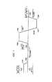
図5を簡単に参照すると、この図は、図2の多段式ポンプ100の動作の種々の区分に対する弁および分注モータのタイミング図を提供している。いくつかの弁が、区分が変化する間に同時に閉状態として図示されているが、弁の閉状態は、圧力スパイクを軽減するために、時刻が若干ずれている(例えば、100ミリ秒)。例えば、排出区分およびパージ区分の間では、隔離弁130は、排出弁145の直前に閉状態となることができる。しかしながら、他の弁のタイミングも、種々の本発明の実施形態において利用できることに留意されるべきである。さらに、区分のうちのいくつかは、一緒に行うことができる(例えば、充填/分注段階は、入口および出口弁の両方が、分注/充填区分で開状態となることができる場合に、同時に行うことができる)。特定の区分は、それぞれのサイクルで反復される必要がないことにさらに留意されるべきである。例えば、パージ区分または静的パージ区分は、すべてのサイクルで行われない場合がある。同様に、排出区分は、すべてのサイクルで行われない場合がある。 Referring briefly to FIG. 5, this figure provides a valve and dispense motor timing diagram for various sections of operation of the
種々の弁の開閉は、多段式ポンプ100内の流体に圧力スパイクを引き起こす可能性がある。出口弁147は、静的パージ区分の間に閉状態であるので、例えば、静的パージ区分の終わりでパージ弁140を閉状態にすると、分注チャンバ185内で圧力の上昇を引き起こす可能がある。それぞれの弁は、閉状態となるとき少量の流体を排出する可能性があるため、これが起こり得る。より具体的には、多くの場合、流体がチャンバ185から分注される前に、パージサイクルおよび/または静的パージサイクルは、多段式ポンプ100から流体を分注する際に、スパッタリングまたは他の摂動を阻止するために、分注チャンバ185から空気を抜くように使用される。しかしながら、静的パージサイクルの終わりには、パージ弁140は、分注の開始に備えて分注チャンバ185を密閉するために閉状態となる。パージ弁140が閉状態になるにつれ、過剰な流体(パージ弁140の保持量にほぼ等しい)が分注チャンバ185中へ付勢され、それによって、流体の分注に対し意図された基準圧力を超えて、分注チャンバ185内の流体の圧力を上昇させる。この過剰な圧力(基準を上回る)は、その後の流体の分注に問題を引き起こす場合がある。パージ弁140を閉状態にすることによって発生する圧力上昇は、分注に望ましい基準圧力より高い割合になる場合があるので、これらの問題は、低圧力を印加する際に悪化することになる。 The opening and closing of the various valves can cause pressure spikes in the fluid within the
より具体的には、パージ弁140を閉状態にすることによって発生する圧力上昇のために、圧力が低下しない場合は、ウエハ上への流体の「吐出」、二重分注、または他の望ましくない流体動態は、その後の分注区分の間に起こることがある。さらに、この圧力上昇は、多段式ポンプ100の動作の間においては一定ではない場合があるので、これらの圧力上昇は、連続的な分注区分の間に、分注される流体の量、または分注の他の特徴に変動を引き起こすことがある。それによって、分注におけるこれらの変動は、ウエハの廃棄およびウエハの再加工の増加の原因になることがある。本発明の実施形態は、分注区分の始まりに対して望ましい始動圧力を達成するために、システム内の種々の弁を閉状態にすることに起因する圧力上昇を明らかにし、分注の前に分注チャンバ185内で達成されるべきほぼどのような基準圧力も可能にすることによって、システムからシステムにわたり異なる上部圧力および機材における他の差異を明らかにする。 More specifically, if the pressure does not decrease due to the pressure increase generated by closing the
一実施形態では、分注チャンバ185内の流体に対する不要な圧力上昇を明らかにするために、静的パージ区分の間に、分注モータ200は、遮断弁135、パージ弁140を閉状態にすること、および/または分注チャンバ185内の圧力上昇を引き起こす可能性がある他の任意の原因によって引き起こされる任意の圧力上昇を補償するために、所定の距離分ピストン192を後退するように反転させてもよい。本明細書に組み込まれる「System and Method for Control of Fluid Pressure」の名称でGeorge GonnellaおよびJames Cedroneが2005年12月2日に出願した米国特許出願第11/292,559号、および「System And Method For Monitoring Operation Of A Pump」の名称でGeorge GonnellaおよびJames Cedroneが、2006年2月28日に出願した米国特許出願第11/364,286号に記載のように、分注チャンバ185内の圧力は、供給ポンプ150の速度を調節することによって制御してもよい。 In one embodiment, during the static purge section, dispense
このようにして、本発明の実施形態は、緩徐な流体操作を特徴とする多段式ポンプを提供する。分注区分の前に分注チャンバ内の圧力変動を補償することによって、不利な潜在的圧力スパイクを回避または軽減することができる。さらに、本発明の実施形態は、プロセス流体上の圧力の悪影響を緩和するのに役立つ他のポンプ制御機構および弁のタイミングを用いることができる。 Thus, embodiments of the present invention provide a multi-stage pump characterized by slow fluid operation. By compensating for pressure fluctuations in the dispensing chamber prior to the dispensing segment, adverse potential pressure spikes can be avoided or reduced. Furthermore, embodiments of the present invention can use other pump control mechanisms and valve timings that help mitigate the adverse effects of pressure on the process fluid.
そのためには、ポンプ装置のチャンバ内の基準圧力を実質的に維持するためのシステムおよび方法に注意が向けられる。本発明の実施形態は、ポンプ装置のチャンバ内で生じ得る圧力変動を補償または考慮するためのモータを制御するように機能してもよい。より具体的には、分注チャンバ内で感知された圧力に基づいて、分注モータは、分注前における分注チャンバ内の基準圧力を実質的に維持するよう制御されてもよい。一実施形態では、分注が開始される前に、分注チャンバ内の圧力が所望の圧力を上回る(または、下回る)か否かを繰り返し判断し、その場合、流体の分注が開始されるまで、ポンプ手段の運動は調整され、分注チャンバ内の所望の圧力を実質的に維持するように、制御ループを利用してもよい。 To that end, attention is directed to systems and methods for substantially maintaining a reference pressure in the chamber of the pump device. Embodiments of the present invention may function to control a motor to compensate or account for pressure fluctuations that may occur in the chamber of the pump device. More specifically, based on the pressure sensed in the dispensing chamber, the dispensing motor may be controlled to substantially maintain a reference pressure in the dispensing chamber prior to dispensing. In one embodiment, before dispensing begins, it is repeatedly determined whether the pressure in the dispensing chamber is above (or below) the desired pressure, in which case fluid dispensing is initiated. Until then, the movement of the pump means is adjusted and a control loop may be utilized to substantially maintain the desired pressure in the dispensing chamber.
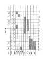
これらの圧力変動の低減は、本発明の一実施形態による多段式ポンプを動作させるための分注チャンバ185での例示的圧力分析データを図示する、図6を参照することによってより理解され得る。地点440において、分注が開始され、分注ポンプ180が流体を出口へ押し出す。分注は、地点445で終了する。分注ポンプ180は、典型的には本段階に関与していないため、分注チャンバ185の圧力は、充填段階の間ほぼ一定のままである。地点450において、濾過段階が開始し、供給段階モータ175が既定速度で正転し、供給チャンバ155から流体を押し出す。図6から分かるように、分注チャンバ185内の圧力は、上昇し始め、地点455で既定の設定点に達する。分注チャンバ185内の圧力が設定点に達すると、分注モータ200は、一定の速度で反転し、分注チャンバ185内の利用可能な容積を増加させる。地点455と地点460との間の圧力分析データの比較的平らな部分では、供給モータ175の速度は、圧力が設定点以下に減少すると増加し、設定点に達すると低下する。これによって、分注チャンバ185内の圧力はほぼ一定の圧力に保たれる。地点460において、分注モータ200がその定位置に達すると、濾過段階は終了する。地点460の急激な圧力スパイクは、濾過終了時の遮断弁135の閉鎖によって生じる。 These pressure fluctuation reductions can be better understood by referring to FIG. 6, which illustrates exemplary pressure analysis data in a dispensing
排出およびパージ区分の後かつ静的パージ区分終了の前に、パージ弁140は閉鎖され、圧力分析データの地点1500で圧力のスパイクが開始する。圧力分析データの地点1500と1502との間から分かるように、分注チャンバ185内の圧力は、この閉鎖によって著しい増加を受け得る。パージ弁140の閉鎖による圧力上昇は、通常一貫しておらず、システムの温度および多段式ポンプ100で利用される流体の粘度に依存する。 After the drain and purge segment and before the end of the static purge segment,
地点1500と1502との間に生じる圧力上昇を考慮し、分注モータ200は、遮断弁135、パージ弁140の閉鎖、および/または他の原因によって生じる圧力上昇を補償するために、ピストン192が既定の距離分後退するように反転させてもよい。ある場合には、パージ弁140は閉鎖に時間を要する可能性があるため、分注モータ200を反転させる前に一定時間遅延させることが望ましい場合がある。このように、圧力分析データの地点1500と1504との間の時間は、パージ弁140を閉鎖するための信号と分注モータ200の反転との間の遅延を反映する。この時間の遅延によって、パージ弁140を完全に閉鎖し、分注チャンバ185内の圧力を実質的に安定させるのに十分となり得、その時間は約50ミリ秒である。 In view of the pressure increase that occurs between
パージ弁140の保持量は、既知量(例えば、製作公差内)であり得るため、分注モータ200は、パージ弁140の保持量にほぼ等しく分注チャンバ185の容積を上昇するために、補償距離分ピストン192を後退させるために反転させてもよい。分注チャンバ185およびピストン192の寸法も既知数であるため、分注モータ200は、特定のモータインクリメント分だけ反転させてもよく、このモータインクリメントによる分注モータ200の反転によって、分注チャンバ185の容積は、パージ弁140の保持量までほぼ増加する。 Since the hold amount of the
分注モータ200の反転を介してピストン192を後退させることの効果によって、地点1504から地点1506での分注にほぼ望ましい基準圧力への分注チャンバ185内の圧力低下がもたらされる。多くの場合、この圧力補償は、次の分注段階において十分な分注を得るために適切であり得る。しかしながら、分注モータ200で利用されるモータの種類またはパージ弁140で利用される弁の種類に応じて、分注チャンバ185の容積を増加させるための分注モータ200の反転によって、分注モータ200の駆動機構内に空間、すなわち「緩み」が生じ得る。この「緩み」は、分注区分の間に、分注モータ200が正転方向に作動し、流体を分注ポンプ180から押し出すと、モータナットアセンブリ等の分注モータ200の構成要素間に一定量の緩みまたは空間が生じることを意味するが、ピストン192が動くように、分注モータ200の駆動アセンブリが物理的に係合する前に、除去する必要がある場合がある。この緩みの量は可変であるため、所望の分注圧力を得るためにどれくらい前方へピストン192を動かすかを判断する際に、この緩みの量を考慮に入れることは困難となり得る。このように、分注モータ200の駆動アセンブリ内のこの緩みによって、各分注区分の間に分注される流体の量の可変性が生じ得る。 The effect of retracting the
その結果、分注区分の前に、分注モータ200の駆動アセンブリ内の緩みの量を実質的にごく少量または存在しないレベルまで低減するように、分注モータ200の最後の運動は、確実に正転方向であることが望ましい。したがって、一部の実施形態では、分注ポンプ200の駆動モータアセンブリ内の望ましくない緩みを考慮し、ピストン192を既定の距離分後退させるために分注モータ200を反転させ、分注チャンバ185内の圧力上昇を生じさせ得る遮断弁135、パージ弁140の閉鎖、および/または他の原因によって生じる圧力上昇を補償してもよく、またさらに超過距離分ピストン192を後退させるために分注モータを反転させ、超過容積を分注チャンバ185に加えてもよい。次いで、分注モータ200を正転方向に係合し、超過距離に実質的に相当する正転方向にピストン192を動かしてもよい。これによって、分注チャンバ185内においてほぼ所望の基準圧力がもたらされ、分注前の分注モータ200の最後の運動が確実に正転方向となり、分注モータ200の駆動アセンブリからいかなる緩みも実質的に排除する。 As a result, prior to dispense segmentation, the final movement of dispense
さらに図6を参照すると、上述のように、圧力分析データ内の地点1500で開始する圧力スパイクは、パージ弁140の閉鎖によって生じ得る。地点1500と1502との間で生じる圧力上昇を考慮すると、遅延後、既定の距離分ピストン192を後退させるために分注モータ200を反転させ、パージ弁140の閉鎖(および/または他の原因)およびさらなる超過距離によって生じる圧力上昇を補償してもよい。上述のように、補償距離によって、パージ弁140の保持量にほぼ等しく分注チャンバ185の容積を増加させてもよい。また、超過距離によって、パージ弁140の保持量にほぼ等しく、あるいは特定の実装に応じて、保持量よりも多くまたは少なく、分注チャンバ185の容積を増加させてもよい。 Still referring to FIG. 6, as described above, a pressure spike starting at
分注モータ200の反転を介して、補償距離および超過距離分ピストン192を後退させる効果によって、地点1504から地点1508において分注チャンバ185の圧力の低下が生じる。次いで、分注モータ200が正転方向に係合され、ピストン192を超過距離に実質的に相当する正転方向に動かしてもよい。ある場合には、分注モータ200を正転方向に係合する前に、分注モータ200を実質的に完全に停止させることが望ましい場合がある。この遅延は、約50ミリ秒であってもよい。分注モータ200の正転係合を介したピストン192の正転運動の効果によって、地点1510から地点1512で分注に望ましいほぼ基準圧力まで分注チャンバ185内の圧力上昇がもたらされ、分注区分前の分注モータ200の最後の運動は、確実に正転方向となり、実質的にすべての緩みが分注モータ200の駆動アセンブリから排除される。静的パージ区分終了時の分注モータ200の反転および正転運動は、図3のタイミング図に描写される。 The effect of reversing the compensation distance and
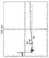
本発明の実施形態は、本発明の一実施形態による多段式ポンプを動作させる特定の区分の間の分注チャンバ185における例示的圧力分析データを図示する、図7を参照することによってより明確に説明され得る。線1520は、流体の分注に望ましい基準圧力を示し、任意の圧力が望ましいが、典型的には、約0psi(例えば、ゲージ圧)、または大気圧である。地点1522において、パージ区分の間、分注チャンバ185内の圧力は、基準圧力1520のわずかに上であってもよい。分注モータ200は、パージ区分終了時に停止し、地点1524で分注チャンバ185内の圧力の低下を開始させ、地点1526でほぼ基準圧力1520に達してもよい。しかしながら、静的パージ区分終了前に、パージ弁140等のポンプ100内の弁を閉鎖させ、圧力分析データの地点1528と1530との間に圧力スパイクを生じさせてもよい。 Embodiments of the present invention will be more clearly understood by referring to FIG. 7, which illustrates exemplary pressure analysis data in dispensing
次いで、分注モータ200を反転させ、補償距離および超過距離(上述のように)分ピストン192を動かし、圧力分析データの地点1532と1534との間で分注チャンバ185内の圧力を基準圧力1520以下に低下させる。分注チャンバ185内の圧力をほぼ基準圧力1520に戻し、分注モータ200の駆動アセンブリから緩みを排除するために、分注モータ200を超過距離に実質的に相当する正転方向に係合させてもよい。この運動によって、圧力分析データの地点1536と1538との間で分注チャンバ185内の圧力が基準圧力1520に戻される。このように、分注チャンバ185内の圧力が分注に望ましい基準圧力に実質的に戻されると、分注モータ200の駆動アセンブリから緩みが排除され、次の分注区分において望ましい分注が達成され得る。 The dispense
上述の本発明の実施形態は、静的パージ区分の間のパージ弁の閉鎖によって生じる圧力上昇のための補償に関連して主に記載されてきたが、これらの同一技術は、多段式ポンプ100の任意の動作段階の間の多段式ポンプ100の内部または外部にかかわらず、いかなる原因によって生じる圧力上昇または低下に対する補償にも適用可能であり、分注チャンバ185からの流路における弁の開閉によって生じる分注チャンバ185内の圧力変化を補償するために特に有用であり得ることは明白であるだろう。 Although the above-described embodiments of the present invention have been described primarily in connection with compensation for pressure rise caused by closure of the purge valve during the static purge section, these same techniques are described in the
また、これらの同一技術は、多段式ポンプ100に関連して使用される他の装置内の変動を補償することによって、分注チャンバ185内の所望の基準圧力を達成するために使用され得ることは明白であるだろう。装置内のこれらの差異、あるいはプロセス、状況、または多段式ポンプ100の内部または外部で使用される装置内の他の変動のより優れた補償のため、分注チャンバ185内で望ましい基準圧力、補償距離、超過距離、遅延時間等の本発明の特定の側面または変数は、ポンプ100のユーザによって構成可能であってもよい。 These same techniques can also be used to achieve a desired reference pressure in dispense
さらに、本発明の実施形態は、圧力変換器112を利用して、分注チャンバ185内の所望の基準圧力を同様に達成してもよい。例えば、パージ弁140の閉鎖(および/または他の原因)によって生じるいかなる圧力上昇をも補償するために、分注チャンバ185内の所望の基準圧力(圧力変換器112によって測定される)が達成されるまで、ピストン192を後退(または、前進させてもよい)させてもよい。同様に、分注前に分注モータ200の駆動アセンブリ内の緩みの量を実質的にごく少量または存在しないレベルまで減少させるために、分注チャンバ185内の圧力が基準圧力以下になるまで、ピストン193を後退させ、次いで、分注チャンバ185内の圧力が分注に望ましい基準圧力に上昇するまで、正転方向に係合させてもよい。 Further, embodiments of the present invention may utilize the
上述のように流体内の圧力変化が考慮されるだけでなく、さらにプロセス流体内の圧力スパイク、または他の圧力変動も、封入空間を生成する弁の閉鎖および封入空間の間の弁の開放を回避することによって、低減することができる。多段式ポンプ100の完全な分注サイクル(例えば、分注区分から分注区分)の間、多段式ポンプ100内の弁は、何度も状態を変化し得る。これらの無数の変化の間、望ましくない圧力スパイクおよび低下が生じる可能性がある。これらの圧力変動が影響を受けやすいプロセス化学物質に損傷を与え得るだけでなく、さらにこれらの弁の開閉によって、流体の分注における途絶または変動を生じる可能性がある。例えば、分注チャンバ185に結合された1つ以上の内部弁の開放によって生じる停滞量内の突然の圧力上昇は、分注チャンバ185内の流体において相当する圧力低下をもたらし、流体内に気泡を生じさせ、それによって次の分注に影響を及ぼし得る。 Not only is pressure variation in the fluid considered as described above, but also pressure spikes in the process fluid, or other pressure fluctuations, can cause the valve closing and opening of the valve between the enclosure spaces to create an enclosure space. By avoiding it, it can be reduced. During a complete dispensing cycle of the multi-stage pump 100 (eg, from dispense segment to dispense segment), the valves in the
多段式ポンプ100内の種々の弁の開閉によって生じる圧力変化を改善するために、種々の弁の開閉および/またはモータの係脱は、これらの圧力スパイクを低減するように調節することができる。概して、本発明の実施形態に従って圧力変化を低減するために、回避可能な場合には弁を閉鎖して流体流路内に閉鎖または封入空間が生じることは決してなく、これに関連して、回避可能な場合には、2つの封入空間の間の弁は開放されない。反対に、多段式ポンプ100外部の領域への開放流体流路、あるいは多段式ポンプ100の外部の大気または条件への開放流体流路(例えば、出口弁147、排出弁145、または入口弁125が開放している)がないならば、弁の開放は回避されるべきである。 In order to improve the pressure changes caused by the opening and closing of the various valves in the
本発明の実施形態による多段式ポンプ100内の弁の開閉のための一般的指針を表す他の方法は、入口弁125、排出弁145、または出口弁147等の外部弁が、弁の開放によってもたらされ得る容積の変化(開放される内部弁の保持量にほぼ等しい)によって生じる圧力変化を排出するために開閉される場合にのみ、多段式ポンプ100の動作中、遮断弁135またはパージ弁140等の多段式ポンプ100内の内部弁は、開閉されることになるということである。これらの指針は、さらに別の方法で考慮されてもよく、多段式ポンプ100内の弁を開放する場合、弁は、外側から開放され(すなわち、外側弁は、内側弁の前に開放されるべきである)、多段式ポンプ100内の弁を閉鎖する場合、弁は、内側から閉鎖されるべきである(すなわち、内側弁は、外側弁の前に閉鎖されるべきである)。 Another way to represent the general guidelines for opening and closing valves in the
また、一部の実施形態では、特定の変化の間に十分な時間がとられ、別の変化(例えば、弁の開閉、モータの始動または停止)が生じる(例えば、起動される)前に、特定の弁が完全に開閉され、モータが完全に始動または停止され、あるいはシステム内の圧力またはシステムの一部が実質的に0psi(例えば、ゲージ圧)もしくは他の0以外のレベルになることを確実にする。多くの場合、100から300ミリ秒の遅延は、多段式ポンプ100内の弁が実質的に完全に開閉するのに十分となるが、しかしながら、これらの技術の特定の用途または実装において利用される実際の遅延は、種々の幅広い他の要因とともに多段式ポンプ100で利用される流体の粘度に、少なくとも部分的に依存してもよい。 Also, in some embodiments, sufficient time is taken between certain changes before another change (eg, opening and closing of a valve, starting or stopping of a motor) occurs (eg, activated), That a particular valve is fully opened and closed, the motor is fully started or stopped, or that the pressure in the system or part of the system is substantially at 0 psi (eg, gauge pressure) or some other non-zero level. to be certain. In many cases, a delay of 100 to 300 milliseconds is sufficient to allow the valves in the
上述の指針は、多段式ポンプ100の動作の種々の区分に対する弁およびモータのタイミングの一実施形態の図を提供し、多段式ポンプ100の動作の間の圧力変化を改善するように機能する、図8Aおよび8Bを参照することによって、より理解され得る。図8Aおよび8Bは、正確な縮尺で描かれてはおらず、番号が付与されたそれぞれの区分は、これらの図内の描写にかかわらず、異なるまたは一意の時間長(0時間を含む)であってもよく、これらの番号が付与された区分のそれぞれの長さは、実装されるユーザレシピ、多段式ポンプ100において利用される弁の種類(例えば、これらの弁の開閉に要する時間)等の種々の幅広い要因に基づいてもよいことは留意されたい。 The above guidelines provide an illustration of one embodiment of valve and motor timing for various sections of operation of the
図8Aを参照すると、時間2010において、準備完了区分信号は、多段式ポンプ100が分注を行う準備が完了したことを示し、その一定時間後、時間2010において、時間2020において入口弁125が開放されるよう1つ以上の信号を送信し、流体を分注するために正転方向に分注モータ200を動作させ、充填チャンバ155へ流体を引き入れるために充填モータ175を反転させてもよい。時間2020の後かつ時間2022の前に(例えば、区分2の間)、流体が出口弁147から分注され得るように、信号が送信され、出口弁147が開放されてもよい。 Referring to FIG. 8A, at
弁信号およびモータ信号のタイミングは、ポンプの種々の弁またはモータ、多段式ポンプ100に関連して実装されるレシピ、あるいは他の要因を作動するために要する時間に基づいて可変であってもよいことは、本開示熟読後明白となるであろう。例えば、図8Aでは、正転方向に分注モータ200を動作させるための信号送信後、出口弁147を開放するための信号が送信されてもよい。なぜなら、本実施例では、出口弁147は、分注モータ200よりも迅速に動作し、したがって、より優れた分注を達成するために実質的に一致するように、出口弁147の開放および分注モータ200の作動を調節することが望ましいためである。しかしながら、他の弁およびモータは、異なる作動速度等を有してもよく、したがって、これらの異なる弁およびモータに対し異なるタイミングが利用され得る。例えば、出口弁147を開放するための信号は、分注モータ200を作動するための信号よりも前または実質的に同時に送信されてもよく、同様に、出口弁200を閉鎖するための信号は、分注モータ200等の動作停止をするための信号よりも前、後、または同時に送信されてもよい。 The timing of the valve signal and motor signal may be variable based on the time required to operate the various valves or motors of the pump, recipes implemented in connection with the
このように、時間2020と2030との間に、流体は、多段式ポンプ200から分注されてもよい。多段式ポンプ200によって実装されているレシピに応じて、異なる量の流体が時間2020と2030との間の異なる地点において分注され得るように、分注モータ200の動作速度は、時間2020と2030との間(例えば、区分2−6のそれぞれにおいて)で可変であってもよい。例えば、区分2の間で区分6の間よりも分注モータ200が迅速に動作し、それに比例して、区分2において区分6よりもより多くの流体が多段式ポンプ200から分注されるように、分注モータは、多項式関数に従って動作してもよい。分注区分発生後の時間2030の前、出口弁147を閉鎖するための信号が送信され、その後、時間2030において、分注モータ200を停止するための信号が送信される。 Thus, during
同様に、2020と2050との間(例えば、区分2−7)、充填モータ175の反転を介して、供給チャンバ155を流体で充満してもよい。次いで、時間2050において、充填モータ175を停止するための信号が送信され、その後充填区分が終了する。充填チャンバ155内の圧力を実質的に0psi(例えば、ゲージ圧)に戻すため、他の作用が生じる前に、入口弁は、時間2050と時間2060との間(例えば、区分9、遅延0)では開放されたままにしてもよい。一実施形態では、この遅延は、約10ミリ秒であってもよい。別の実施形態では、時間2050と時間2060との間の時間は、可変であってもよく、充填チャンバ155内の圧力測定値に依存してもよい。例えば、圧力変換器を利用して、充填チャンバ155内の圧力を測定してもよい。圧力変換器が充填チャンバ155内の圧力が0psiに達したことを示すと、時間2060において区分10を開始してもよい。 Similarly,
次いで、時間2060において、隔離弁130を開放するための信号が送信され、隔離弁130が完全に開放されるのに十分な長さの好適な遅延(例えば、約250ミリ秒)後、時間2070において、遮断弁135を開放するための信号が送信される。再び、遮断弁135が完全に開放されるのに十分な長さの好適な遅延(例えば、約250ミリ秒)後、時間2080において、入口弁125を閉鎖するための信号が送信される。入口弁125が完全に開放される好適な遅延(例えば、約350ミリ秒)後、前濾過および濾過区分(例えば、区分13および14)の間充填モータ175が作動し、濾過区分(例えば、区分14)の間分注モータ200が作動するように、時間2090において、充填モータ175を作動するための信号が送信されてもよく、時間2100において、分注モータ200を作動するための信号が送信されてもよい。時間2090と時間2100との間の時間は、濾過される流体の圧力が既定の設定点に達することを可能にする運動またはモータに対する設定時間または設定距離である、あるいは上述のような圧力変換器を使用して判断され得る、前濾過区分であってもよい。 Then, at
あるいは、圧力変換器を利用して、流体の圧力を測定してもよく、圧力変換器が流体の圧力が設定点に達したことを示すと、時間2100において、濾過区分14を開始してもよい。これらのプロセスの実施形態は、「System and Method for Control of Fluid Pressure」の名称でGeorge GonnellaおよびJames Cedroneが2005年12月2日に出願した米国特許出願第11/292,559号、および「System and Method for Monitoring Operation of a Pump」の名称でGeorge GonnellaおよびJames Cedroneが出願した米国特許出願第11/364,286号により完全に記載されており、参照することによって本明細書に組み込まれる。 Alternatively, a pressure transducer may be utilized to measure the pressure of the fluid, and when the pressure transducer indicates that the fluid pressure has reached the set point, at
濾過区分後、時間2110において、充填モータ175および分注モータ200の動作を停止するための1つ以上の信号が送信される。時間2100と時間2110との間(例えば、濾過区分14)の長さは、所望の濾過速度、充填モータ175および分注モータ200の速度、または流体の粘度等に応じて、可変であってもよい。一実施形態では、分注モータ200が定位置に達すると、時間2110において濾過区分が終了してもよい。 After the filtration segment, at
充填モータ175および分注モータ200を完全に停止させるための好適な遅延後(まったく時間が必要ない場合もある(例えば、遅延なし))、時間2120において、排出弁145を開放するための信号が送信される。図8Bに移ると、排出弁145を完全に開放するための好適な遅延(例えば、約225ミリ秒)後、時間2130において、充填モータ175に信号が送信され、排出区分(例えば、区分17)のためのステッピングモータ175が作動する。排出区分の間の圧力変換器112によって多段式ポンプ100内の流体の圧力を監視するため、排出区分の間遮断弁135を開放したままにしてもよいが、時間2130において、排出区分の開始前に遮断弁135を閉鎖してもよい。 After a suitable delay to completely stop
排出区分を終了するため、時間2140において、充填モータ175の動作を停止するための信号が送信される。所望に応じて、例えば、排出区分の間の流体の圧力が高い場合、時間2140と2142との間に、流体の圧力が好適に消散させるように遅延(例えば、約100ミリ秒)を要してもよい。時間2142と2150との間の時間は、一実施形態では、0圧力時の変換器112に対して使用し、約10ミリ秒であってもよい。 At time 2140, a signal for stopping the operation of the filling
次いで、時間2150において、遮断弁125を閉鎖するための信号が送信される。時間2150に続いて、遮断弁125が完全に閉鎖可能なように(例えば、約250ミリ秒)、好適な遅延が配分される。次いで、時間2160において、隔離弁130を閉鎖するための信号が送信され、隔離弁130が完全に閉鎖する好適な遅延(例えば、約250ミリ秒)後、時間2170において、排出弁145を閉鎖するための信号が送信される。排出弁140が完全に閉鎖し得るように、好適な遅延(例えば、約250ミリ秒)が配分され、その後、時間2180において、入口弁125を開放するための信号が送信され、入口弁125が完全に開放する好適な遅延後(例えば、約250ミリ秒)、時間2190において、パージ弁140を開放するための信号が送信される。 Then, at
排出弁145を完全に開放する好適な遅延(例えば、約250ミリ秒)後、時間2200において、分注モータ200に信号が送信され、パージ区分(例えば、区分25)のために分注モータ200を始動し、レシピに応じて、パージ区分のための時間後、時間2210において、分注モータ200を停止するための信号が送信され、パージ区分を終了することができる。時間2210と2212との間において、分注チャンバ185内の圧力が0psi(例えば、約10ミリ秒)に実質的に安定し得るように、十分な時間(例えば、既定または圧力変換器112の使用による判断)が配分される。続いて、時間2220において、パージ弁140を閉鎖するための信号が送信され、パージ弁140が完全に閉鎖するための十分な遅延(例えば、約250ミリ秒)が配分された後、時間2230において、入口弁125を閉鎖するための信号が送信されてもよい。多段式ポンプ100内の弁の閉鎖によって生じた圧力変化を補償するために分注モータ200を作動させた後(上述のように)、時間2010において、多段式ポンプ100は、分注を行うために再び準備完了状態となってもよい。 After a suitable delay (eg, about 250 milliseconds) to fully
準備完了区分と分注区分との間において、一定の遅延があってもよいことは留意されたい。多段式ポンプ100が準備完了区分を開始すると、遮断弁135および隔離弁130は閉鎖されてもよいため、この充填または次の充填の間に分注が始動されるかにかかわらず、多段式ポンプの次の分注に影響を及ぼすことなく、充填チャンバ155に流体を導入することができるようにしてもよい。 Note that there may be a certain delay between the ready and dispense segments. When
多段式ポンプ100が準備完了状態にある間に充填チャンバ155を充填するステップは、多段式ポンプ100の動作の種々の区分に対する弁およびモータのタイミングの別の実施形態の図を提供し、多段式ポンプ100の動作の間の圧力変化を改善するように機能する、図9Aおよび9Bを参照することによってより明確に描写され得る。 The step of filling the
図9Aを参照すると、時間3010において、準備完了区分信号は、多段式ポンプ100が分注を行う準備が完了したことを示し、その一定時間後、時間3012において、出口弁147を開放するための信号が送信されてもよい。出口弁147を開放させるための好適な遅延後、時間3020において、正転方向に分注モータ200を動作させ、出口弁147から流体を分注し、充填モータ175を反転させ、流体を充填チャンバ155に引き込むための1つ以上の信号が送信されてもよい(より完全に後述するように、入口弁125は、前の充填区分から依然として開放されたままでもよい)。時間3030において、分注モータ200を停止するための信号が送信され、時間3040において、出口弁147を閉鎖するための信号が送信されてもよい。 Referring to FIG. 9A, at
弁信号およびモータ信号のタイミングは、ポンプの種々の弁またはモータ、多段式ポンプ100に関連して実装されるレシピ、あるいは他の要因を作動するために要する時間に基づいて可変であってもよいことは、本開示熟読後明白となるであろう。例えば(図8Aに描写されるように)、正転方向に分注モータ200を動作させるための信号送信後、出口弁147を開放するための信号が送信されてもよい。なぜなら、本実施例では、出口弁147は、分注モータ200よりも迅速に動作し、したがって、より優れた分注を達成するために実質的に一致するように、出口弁147の開放および分注モータ200の作動を調節することが望ましいためである。しかしながら、他の弁およびモータは、異なる作動速度等を有してもよく、したがって、これらの異なる弁およびモータに対し異なるタイミングが利用され得る。例えば、出口弁147を開放するための信号は、分注モータ200を作動するための信号よりも前または実質的に同時に送信されてもよく、同様に、出口弁200を閉鎖するための信号は、分注モータ200等の動作停止をするための信号よりも前、後、または同時に送信されてもよい。 The timing of the valve signal and motor signal may be variable based on the time required to operate the various valves or motors of the pump, recipes implemented in connection with the
このように、時間3020と3030との間に、流体は、多段式ポンプ200から分注されてもよい。多段式ポンプ200によって実装されているレシピに応じて、異なる量の流体が時間3020−3030との間の異なる地点において分注され得るように、分注モータ200の動作速度は、時間3020と3030との間(例えば、区分2−6のそれぞれにおいて)で可変であってもよい。例えば、区分2の間で区分6の間よりも分注モータ200が迅速に動作し、それに比例して、区分2において区分6よりもより多くの流体が多段式ポンプ200から分注されるように、分注モータは、多項式関数に従って動作してもよい。分注区分発生後の時間3030の前、出口弁147を閉鎖するための信号が送信され、その後、時間2030において、分注モータ200を停止するための信号が送信される。 Thus, during
同様に、3020と3050との間(例えば、区分2−7)、充填モータ175の反転を介して、供給チャンバ155を流体で充満してもよい。次いで、時間3050において、充填モータ175を停止するための信号が送信され、その後充填区分が終了する。充填チャンバ155内の圧力を実質的に0psi(例えば、ゲージ圧)に戻すため、他の作用が生じる前に、入口弁は、時間3050と時間3060との間(例えば、区分9、遅延0)では開放されたままにしてもよい。一実施形態では、この遅延は、約10ミリ秒であってもよい。別の実施形態では、時間3050と時間3060との間の時間は、可変であってもよく、充填チャンバ155内の圧力測定値に依存してもよい。例えば、圧力変換器を利用して、充填チャンバ155内の圧力を測定してもよい。圧力変換器が充填チャンバ155内の圧力が0psiに達したことを示すと、時間3060において区分10を開始してもよい。 Similarly, the
次いで、時間3060において、隔離弁130を開放するための信号が送信され、時間3070において、遮断弁135を開放するための信号が送信される。次いで、時間3080において、入口弁125を閉鎖するための信号が送信され、その後、前濾過および濾過区分の間充填モータ175が作動し、濾過区分の間分注モータ200が作動するように、時間3090において、充填モータ175を作動するための信号が送信され、時間3100において、分注モータ200を作動するための信号が送信されてもよい。 Then, at time 3060, a signal for opening
濾過区分後、時間3110において、充填モータ175および分注モータ200の動作を停止するための1つ以上の信号が送信される。時間3120において、排出弁145を開放するための信号が送信される。図9Bに移ると、時間3130において、充填モータ175に信号が送信され、排出区分のためのステッピングモータ175を作動させてもよい。排出区分を終了するため、時間3140において、充填モータ175の動作を停止するための信号が送信される。次いで、時間3150において、遮断弁125を閉鎖するための信号が送信され、時間3160において、隔離弁130を閉鎖するための信号が送信され、時間3170において、排出弁145を閉鎖するための信号が送信される。 After the filtration segment, at time 3110, one or more signals are sent to stop the operation of
時間3180において、入口弁125を開放するための信号が送信され、その後、時間3190において、パージ弁140を開放するための信号が送信される。次いで、時間3200において、分注モータ200に信号が送信され、パージ区分のための分注モータ200を開始し、パージ区分後、時間3210において、分注モータ200を停止するための信号を送信することができる。 At time 3180, a signal for opening the
続いて、時間3220において、パージ弁140を閉鎖するための信号が送信され、その後時間3230において、入口弁125を閉鎖するための信号が送信されてもよい。多段式ポンプ100内の弁の閉鎖によって生じた圧力変化を補償するために分注モータ200を作動させた後(上述のように)、時間3010において、多段式ポンプ100は、分注を行うために再び準備完了状態となってもよい。 Subsequently, at time 3220, a signal for closing
時間3010において多段式ポンプ100が準備完了区分を開始すると、入口弁125を開放するための信号が送信され、多段式ポンプ100が準備完了状態にある間に流体が充填チャンバ175に引き込まれるように、充填モータ175を反転させるための別の信号が送信されてもよい。遮断弁135および隔離弁130は閉鎖されており、充填チャンバ155は分注チャンバ185から実質的に分離しているため、準備完了区分の間に充填チャンバ155が流体で充填されていても、準備完了区分を開始後のいずれの地点においても、この充填によって流体を分注する多段式ポンプ100の能力に影響が及ぼされることは決してない。さらに、充填が完了する前に分注が始動される場合、充填は、多段式ポンプ100からの流体の分注と実質的に同時に継続してもよい。 When
多段式ポンプ100が最初に準備完了区分を開始する際、分注チャンバ185内の圧力は、分注区分に対しほぼ所望の圧力であってもよい。しかしながら、準備完了区分開始時点と分注区分開始時点との間に一定の遅延があってもよく、分注チャンバ185内の分注段階ダイヤフラム190の特性、温度変化、または様々な他の要因等の種々の要因に基づいて、分注チャンバ185内の圧力は、準備完了区分の間変動してもよい。その結果、分注区分が開始されると、分注チャンバ185内の圧力は、分注に望ましい基準圧力から比較的急激に変動し得る。 When the
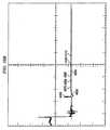
この変動は、図10Aおよび10Bを参照することによって、より明確に実証され得る。図10Aは、分注チャンバ185における例示的圧力分析データを描写し、準備完了区分の間の分注チャンバ内の圧力における変動を示す。図22および23を参照して上述したように、ほぼ地点4010において、弁運動または別の原因によって生じた圧力変化のための補償が行われてもよい。この圧力補償によって、多段式ポンプ100が準備完了区分を開始し得るほぼ地点4020において、分注チャンバ185内の圧力を分注に望ましいほぼ基準圧力(線4030によって示される)に補償してもよい。以上のように、ほぼ地点4020において準備完了区分を開始後、分注チャンバ185内の圧力は、上述のような種々の要因によって安定した上昇を受け得る。次いで、次の分注区分が生じると、基準圧力4030からのこの圧力変動によって、不十分な分注がもたらされ得る。 This variation can be more clearly demonstrated by referring to FIGS. 10A and 10B. FIG. 10A depicts exemplary pressure analysis data in dispense
また、準備完了区分と次の分注区分との開始時点の間の遅延時間は可変であって、分注チャンバ185内の圧力変動は遅延時間と相関し得るため、連続する分注区分のそれぞれにおいて生じる分注は、異なる遅延の間生じ得る異なる量によって、可変であってもよい。このように、この圧力変動によっても、多段式ポンプ100の能力に影響を及ぼし、正確に分注を繰り返し、それによって、プロセスレシピの重複における多段式ポンプ100の使用を阻止してもよい。したがって、多段式ポンプ100の準備完了区分の間、基準圧力を実質的に維持し、次の分注区分の間の分注および分注区分全体の分注の再現性を改善し、同時に許容可能な流体力学を達成することが望ましい。 Also, since the delay time between the start time of the ready segment and the next dispense segment is variable and the pressure fluctuation in the dispense
一実施形態では、準備完了区分の間、基準圧力を実質的に維持するために、分注モータ200は、分注チャンバ185内で生じ得る上方(または、下方)圧力変動を補償または考慮するよう制御することができる。より具体的には、分注モータ200は、「不動帯」閉ループ圧力制御を使用して、基準分注チャンバ185内の圧力を実質的に維持するよう制御してもよい。簡単に図2を参照すると、圧力センサ112は、一定の間隔でポンプ制御装置20に圧力測定値を報告してもよい。報告される圧力が一定量または許容量だけ所望の基準圧力から逸脱する場合、ポンプ制御装置20は、分注モータ200に信号を送信し、ポンプ制御装置20で検知可能である分注モータ200が移動可能な最小距離分(モータインクリメント)反転(または、正転)させ、したがって、ピストン192および分注段階ダイヤフラム190を後退(または、前進)させ、それに比例した分注チャンバ185内の圧力の低下(または、上昇)を生じさせてもよい。 In one embodiment, dispense
圧力センサ112が分注チャンバ185内の圧力を抽出および報告する周波数が、分注モータ200の動作速度と比較して若干早い場合、別の圧力測定結果がポンプ制御装置20によって受信または報告される前に、分注モータ200がその運動を完了し得るように、ポンプ制御装置20は、圧力センサ112によって報告された圧力測定結果を処理しない、あるいは分注モータ200へ信号を送信する前後の一定時間枠の間圧力センサ112を無効にする場合がある。別様に、ポンプ制御装置20は、圧力センサ112によって報告された圧力測定結果を処理する前に、分注モータ200がその運動を完了したことが検出されるまで待機してもよい。多くの実施形態では、圧力センサ112が分注チャンバ185内の圧力を抽出し、この圧力測定を報告する抽出間隔は、約30khz、約10khz、または別の間隔であってもよい。 If the frequency at which the
しかしながら、上述の実施形態には、課題が伴う。ある場合には、これらの実施形態の1つ以上は、上述のように、準備完了区分と次の分注区分との開始時点の間の遅延時間が可変である場合、分注において著しい変動を示す可能性がある。準備完了区分と次の分注区分との開始時点の間の固定遅延時間を利用することによって、これらの課題のある程度は軽減され、再現性が向上され得るが、しかしながら、特定のプロセスを実装する場合には、これは常に実現可能とは限らない。 However, the above-described embodiments have problems. In some cases, one or more of these embodiments may cause significant variations in dispensing when the delay time between the start of the ready segment and the next dispensing segment is variable, as described above. May show. By utilizing a fixed delay time between the start of the ready segment and the next dispense segment, some of these challenges may be reduced and reproducibility improved, however, implementing a specific process In some cases this is not always feasible.
多段式ポンプ100の準備完了区分の間、基準圧力を実質的に維持しながら、分注の再現性を向上させるため、一部の実施形態では分注モータ200は、分注チャンバ185内で生じ得る圧力変動を補償または考慮するために、閉ループ圧力制御を使用して制御することができる。圧力センサ112は、一定の間隔(上述のように、一部の実施形態では、この間隔は、約30khz、約10khz、または別の間隔であってもよい)で、圧力測定値をポンプ制御装置20に報告してもよい。報告された圧力が所望の基準圧力を上回る(または、下回る)場合、ポンプ制御装置20は、信号を分注モータ200に送信し、モータインクリメントによって分注モータ200を反転(または、正転)させ、したがって、ピストン192および分注段階ダイヤフラム190を後退(または、前進)させ、分注チャンバ185内の圧力を低下(または、上昇)させてもよい。この圧力監視および補償は、分注区分が開始するまで、実質的に継続的に生じてもよい。このように、ほぼ所望の基準圧力が、分注チャンバ185内で維持され得る。 In some embodiments, the dispense
上述のように、圧力センサ112が分注チャンバ185内の圧力を抽出および報告する周波数は、分注モータ200の動作速度と比較して若干早い場合がある。この差異を考慮し、別の圧力測定結果がポンプ制御装置20によって受信または報告される前に、分注モータ200がその運動を完了し得るように、ポンプ制御装置20は、圧力センサ112によって報告された圧力測定結果を処理しない、あるいは分注モータ200へ信号が送信される前後の一定の時間枠の間圧力センサ112を無効にしてもよい。別様に、ポンプ制御装置20は、圧力センサ112によって報告された圧力測定結果を処理する前に、分注モータ200がその運動を完了したという通知を検出または受信するまで、待機してもよい。 As described above, the frequency at which the
前述のように、基準圧力を実質的に維持するための閉ループ制御システムの実施形態を利用することの有益な効果は、準備完了区分の間、閉ループ制御システムのまさにそのような実施形態を採用した分注チャンバ185の例示的圧力分析データを描写した、図10Bを参照することによって容易に明らかとなり得る。図6および7に関して上述のように、ほぼ地点4050において、弁運動または別の原因によって生じた圧力変化のための補償が行われ得る。この圧力補償は、多段式ポンプ100が準備完了区分を開始するほぼ地点4060において、分注チャンバ185内の圧力を分注に望ましいほぼ基準圧力(線4040によって示される)に補償し得る。ほぼ地点4060において、準備完了区分開始後、閉ループ制御システムの実施形態は、準備完了区分の間の圧力の変動を考慮し、所望の基準温度に実質的に維持してもよい。例えば、地点4070において、閉ループ制御システムは、圧力上昇を検出して、この圧力上昇を考慮し、基準圧力4040に実質的に維持してもよい。同様に、地点4080、4090、4100、4110において、閉ループ制御システムは、分注チャンバ185内の圧力変動を考慮または補償し、準備完了区分の長さにかかわらず、所望の基準圧力4040に実質的に維持してもよい(地点4080、4090、4100、および4110は、代表例のみであって、閉ループ制御システムによる他の圧力補償は、図10Bに記載されているが、参照番号を付与しておらず、したがって説明されないことは留意されたい)。その結果、前記準備完了区分の間、閉ループ制御システムによって所望の基準圧力4040が分注チャンバ185内で実質的に維持されるため、より十分な分注が次の分注区分において達成され得る。 As previously mentioned, the beneficial effect of utilizing an embodiment of a closed loop control system to substantially maintain a reference pressure is the adoption of just such an embodiment of the closed loop control system during the ready segment. It may be readily apparent by referring to FIG. 10B depicting exemplary pressure analysis data for dispense
しかしながら、次の分注区分の間、このような十分な分注を達成するために、分注モータ200を作動して、分注チャンバ185から流体を分注する場合、基準圧力を実質的に維持するようになされる補償を考慮することが望ましい。より具体的には、地点4060において、圧力補償が生じ、多段式ポンプ100が最初に準備完了区分を開始した直後は、分注段階ダイヤフラム190は、最初の位置にある場合がある。この最初の位置から所望の分注を達成するために、分注段階ダイヤフラム190は、分注位置に移動されるべきである。しかしながら、上述のように、圧力変動のための補償後、分注段階ダイヤフラム190は、最初の位置と異なる第2の位置にある場合がある。一部の実施形態では、分注段階ダイヤフラム190を所望の分注を達成する分注位置へ移動させることによって、この差異は、分注区分の間考慮されるべきである。言い換えると、所望の分注を達成するために、分注段階ダイヤフラム190は、多段式ポンプ100が準備完了区分の最初の開始時に、準備完了区分の間の圧力変動のための補償が生じた後、その第2の位置から分注段階ダイヤフラム190の最初の位置へ移動され、その後分注段階ダイヤフラム190は、最初の位置から分注位置への距離分移動されてもよい。 However, during the next dispensing segment, in order to achieve such a sufficient dispensing, when the dispensing
一実施形態では、多段式ポンプ100が準備完了区分を最初に開始した時に、ポンプ制御装置20は、最初の距離(分注距離)を計算し、所望の分注を達成するために分注モータ200を移動させてもよい。多段式ポンプ100が準備完了区分にある間に、ポンプ制御装置20は、分注モータ200が準備完了区分(補償距離)の間生じた圧力変動の補正のために移動した距離を記録してもよい。分注段階の間、所望の分注を達成するために、ポンプ制御装置20は、分注モータ200に信号を送信して、補正距離に分注距離を加えた(または、差し引いた)距離だけ移動させてもよい。 In one embodiment, when the
しかしながら、他の場合において、分注モータ200を作動させ、分注チャンバ185から流体を分注する場合に、これらの圧力補償を考慮することが望ましくない可能性がある。より具体的には、地点4060において、圧力補償が生じ、多段式ポンプ100が準備完了区分を最初に開始した直後、分注段階ダイヤフラム190は、最初の位置にある場合がある。この最初の位置から所望の分注を達成するために、分注段階ダイヤフラム190は、分注距離分移動されるべきである。上述のように、圧力変動のための補償後、分注段階ダイヤフラム190は、最初の位置と異なる第2の位置にある場合がある。一部の実施形態では、分注段階ダイヤフラム190を分注距離(第2の位置から開始)分単に移動させることによって、所望の分注が達成され得る。 However, in other cases it may not be desirable to consider these pressure compensations when operating the dispense
一実施形態では、多段式ポンプ100の最初の準備完了区分開始時に、ポンプ制御装置20は、最初の距離を計算し、所望の分注を達成するために分注モータ200を移動させてもよい。次いで、分注段階の間、所望の分注を達成するために、準備完了区分の間、分注モータ200が圧力変動を補償するために移動した距離にかかわらず、ポンプ制御装置20は、分注モータ200に信号を送信し、この最初の距離を移動させてもよい。 In one embodiment, at the beginning of the first ready segment of the
所与の状況において利用または適用される上述の実施形態の1つの選択は、他の中から選択された実施形態に関連して採用されたシステム、装置、または実験条件等の多数の要因の依存することになることは明白であろう。また、基準圧力を実質的に維持するための制御システムの上述の実施形態は、準備完了区分の間の上昇圧力変動を考慮して記載されているが、これら同一のシステムおよび方法の実施形態は、多段式ポンプ100の準備完了区分または任意の他の区分における上昇または下降圧力変動の考慮に対し等しく適用可能であることは明白であろう。さらに、本発明の実施形態は、多段式ポンプ100に関して記載されたが、これらの発明の実施形態(例えば、制御方法等)は、単段階または事実上任意の他の種類のポンプ装置に等しく適用され、効果的に利用され得ることは理解されることであろう。 The selection of one of the above-described embodiments to be utilized or applied in a given situation depends on a number of factors such as the system, apparatus, or experimental conditions employed in relation to the embodiment selected from among others. It will be obvious that it will do. Also, although the above-described embodiments of the control system for substantially maintaining the reference pressure have been described in view of rising pressure fluctuations during the ready section, embodiments of these same systems and methods are described. It will be apparent that the present invention is equally applicable to the consideration of rising or falling pressure fluctuations in the ready section of the
ここで、本発明の種々の実施形態に関連して利用され得るまさにそのような単段ポンプ装置の実施例を記載することは有用であろう。図11は、ポンプ4000のためのポンプアセンブリの一実施形態の図である。ポンプ4000は、上述の多段式ポンプ100の1段階、例えば分注段階に類似しており、ステッピング、ブラシレスDC、または他のモータによって駆動される回転ダイヤフラムポンプを含むことができる。ポンプ4000は、ポンプ4000を通る種々の流体流路を画定する、またポンプチャンバを少なくとも部分的に画定する分注ブロック4005を含むことができる。一実施形態による、分注ポンプブロック4005は、PTFE、修飾PTFEまたは他の材料から成る単一ブロックであってもよい。これらの材料は、多くのプロセス流体と反応しない、または反応性が少ないので、これらの材料を使用すると、流通路およびポンプチャンバは、最低限のハードウェアの追加をもって、分注ブロック4005に直接機械加工することができる。ひいては、分注ブロック4005は、一体型流体マニホールドを提供することによって、パイピングの必要性を軽減する。 It would be useful to describe an example of just such a single stage pumping device that can be utilized in connection with various embodiments of the present invention. FIG. 11 is a diagram of one embodiment of a pump assembly for
分注ブロック4005は、例えば、流体を受ける入口4010、流体をパージ/排出するためのパージ/排出出口4015、および流体が分注区分の間に分注される分注出口4020を含み、種々の外部入口および外部出口を含むことができる。図11の実施例では、ポンプがたった1つのチャンバを有するので、分注ブロック4005は、外部パージ出口4010を含む。参照することによって本明細書に全面的に組み込まれる、「O−Ring−Less Low Profile Fitting and Assembly Thereof」の名称で、Iraj Gashgaeeが2005年12月2日に出願した米国仮特許出願第60/741,660号、および「O−Ring−Less Low Profile FITTINGS and Fitting Assemblies」名称で、Iraj Gashgaeeが______に出願した米国特許出願第______号[ENTG1760−1]は、分注ブロック4005の外部入口および外部出口を流体管路に接続ために利用することができる取付部品の実施形態を記載している。
分注ブロック4005は、入口から入口弁(例えば、弁板4030によって少なくとも部分的に画定される)へ、入口弁からポンプチャンバへ、ポンプチャンバから排出/パージ弁へ、およびポンプチャンバから出口4020へ流体を送る。ポンプカバー4225は、ポンプモータを破損から保護することができるが、ピストンハウジング4027は、ピストンを保護することができ、本発明の一実施形態により、ポリエチレンまたは他のポリマーから形成することができる。弁板4030は、流体の流れをポンプ4000の種々の構成要素に誘導するように構成することができる弁(例えば、入口弁、およびパージ/排出弁)のシステムのための弁ハウジングを提供する。弁板4030および対応する弁は、上述の弁板230と併せて記載した方法と同様に形成することができる。一実施形態によると、入口弁、およびパージ/排出弁のそれぞれは、弁板4030に少なくとも部分的に統合され、圧力または真空が対応するダイヤフラムに印加されるか否かに応じて開状態または閉状態となるダイヤフラム弁である。他の実施形態では、弁のいくつかのは、分注ブロック4005の外部にあってもよく、またはさらなる弁板に配置してもよい。一実施形態によると、1枚のPTFEは、弁板4030と分注ブロック4005との間に挟入され、種々の弁のダイヤフラムを形成する。弁板4030は、それぞれの弁のための弁制御入口(図示せず)を含み、対応するダイヤフラムに圧力または真空を印加する。
多段式ポンプ100と同様に、ポンプ4000は、流体液滴が、電子機器を収納する多段式ポンプ100の領域に入らないようにするいくつかの特性を含むことができる。「防滴」の特性は、突出しているリップ、傾斜特性、構成要素間の密閉部、金属/ポリマーの接続部分でのオフセット、および電子機器を液滴から隔離するために上述した他の特性を含むことができる。電子機器ならびにマニホールドは、ポンプチャンバ内の流体上の熱効果を軽減するために上述した方法と同様に構成することができる。このようにして、形状因子および熱効果を減少させるため、また流体が電子ハウジングに入らないようにするために、多段式ポンプに使用されるものと同様の特性は、単段ポンプに使用することができる。 Similar to
また、上述の制御方法の多くは、ポンプ4000と関連して使用し、実質的に十分な分注を達成し得る。例えば、本発明の実施形態は、ポンプ4000の弁を制御するために使用され、(例えば、ポンプ装置の外部領域への)ポンプ装置を通る流体流路が閉鎖される時間を実質的に最小限にするよう構成された弁シーケンスに従って、ポンプ装置の弁システムを作動するよう保証してもよい。さらに、特定の実施形態では、ポンプ4000が動作中の弁の状態変化の間に十分な時間をとり、別の変化が開始される前に、特定の弁が完全に開閉されることを確実にする。例えば、ポンプ4000のモータの運動は、十分な時間遅延され、充填段階前にポンプ4000の入口弁が完全に開放されることを確実にしてもよい。 Also, many of the control methods described above can be used in conjunction with
同様に、ポンプ装置のチャンバ内で生じ得る圧力変動を補償または考慮するためのシステムおよび方法の実施形態は、実質的に等しい効果を有してポンプ4000に適用され得る。分注モータは、分注チャンバ内で感知された圧力に基づく分注の前に、分注チャンバ内の基準圧力を実質的に維持するように制御されてもよく、制御ループは、分注チャンバ内の圧力が所望の圧力(例えば、上昇または低下)と異なるか否かを繰り返し判断するように利用されてもよく、その場合、ポンプ手段の運動は、分注チャンバ内の所望の圧力を実質的に維持するように調整される。 Similarly, embodiments of systems and methods for compensating or taking into account pressure fluctuations that can occur in the chamber of the pump apparatus can be applied to the
ポンプ4000のチャンバ内の圧力調整は事実上いつ生じてもよいが、分注区分が開始される前が特に有用となり得る。より具体的には、ポンプ4000の最初の準備完了区分開始時、分注チャンバ185内の圧力は、次の分注区分またはその一部に対しほぼ所望の圧力(例えば、較正または以前の分注から判断された分注圧力)である基準圧力である場合ある。この所望の分注圧力は、所望の流速、流量等の所望の一連の特性を有する分注を達成するために利用してもよい。出口弁が開放する前に常に分注チャンバ185内の流体をこの所望の基準圧力に持ってくることによって、分注区分に先立ってポンプ4000の構成要素の整合性および変動を考慮することができ、十分な分注が達成され得る。 A pressure adjustment in the chamber of the
しかしながら、準備完了区分と分注区分との開始時点の間に一定の遅延があるため、ポンプ4000のチャンバ内の圧力は、種々の要因に基づいて準備完了区分の間変化し得る。この圧力変動に対処するため、所望の基準圧力がポンプ4000のチャンバ内で実質的に維持され、次の分注区分において十分な分注が達成されるように、本発明の実施形態を利用してもよい。 However, because there is a certain delay between the start time of the ready section and the dispense section, the pressure in the chamber of the
単段ポンプ内の圧力変動のための制御に加え、本発明の実施形態を使用して、ポンプ4000内部の種々の機構または構成要素あるいはポンプ4000に関連して使用される装置の作動によって生じる、分注チャンバ内の圧力変動を補償してもよい。 In addition to control for pressure fluctuations within a single stage pump, embodiments of the present invention may be used to cause various mechanisms or components within
本発明の一実施形態は、分注区分(または、任意の他の区分)の開始前にパージまたは排出弁を閉鎖することによって生じるポンプのチャンバ内の圧力変化を補償してもよい。この補償は、多段式ポンプ100に関して上述したものと同様に、パージまたは入口弁が閉鎖された場合に、ポンプ4000のチャンバの容積がそのような弁の保持量分実質的に増加するように、ポンプ4000のモータを反転させることによって作動してもよい。 One embodiment of the invention may compensate for pressure changes in the pump chamber caused by closing the purge or drain valve prior to the start of the dispense segment (or any other segment). This compensation is similar to that described above for
このようにして、本発明の実施形態は、緩徐な流体操作を特徴とする多段式ポンプを提供する。弁の開閉および/またはポンプ装置内のモータの作動のシーケンス決定によって、潜在的に損傷を及ぼし得る圧力スパイクが回避または緩和することができる。さらに、本発明の実施形態は、プロセス流体上の圧力の悪影響を緩和するのに役立つ他のポンプ制御機構および弁のタイミングを用いることができる。 Thus, embodiments of the present invention provide a multi-stage pump characterized by slow fluid operation. By sequencing the opening and closing of the valves and / or the operation of the motor in the pumping device, potentially damaging pressure spikes can be avoided or mitigated. Furthermore, embodiments of the present invention can use other pump control mechanisms and valve timings that help mitigate the adverse effects of pressure on the process fluid.
上述の明細書では、本発明は、特定の実施形態を参照して記載されてきた。しかしながら、以下の請求項に記載の本発明の範囲から逸脱することなく、種々の修正および変更がなされ得ることは、当業者には理解されるであろう。したがって、明細書および図面は、限定的意味よりも例証としてみなされ、そのような修正はすべて発明の範囲内に含まれるものと意図される。 In the foregoing specification, the invention has been described with reference to specific embodiments. However, one of ordinary skill in the art appreciates that various modifications and changes can be made without departing from the scope of the present invention as set forth in the claims below. The specification and drawings are accordingly to be regarded in an illustrative rather than a restrictive sense and all such modifications are intended to be included within the scope of the invention.
効果、他の利点、および課題解決手段が、特定の実施形態に関して上述されてきた。しかしながら、そのような効果、利点、課題解決手段、および効果、利点、または解決手段をもたらし得る、生じるもしくはより顕著となる任意の構成要素は、いずれかまたはすべての請求項に重要、必要、または不可欠な特徴あるいは構成要素であると解釈されない。 Benefits, other advantages, and solutions have been described above with regard to specific embodiments. However, any effect, advantage, problem-solving means, and any components that may or may result in an effect, advantage, or solution are important, necessary, or necessary in any or all claims. It is not interpreted as an essential feature or component.
Claims (20)
Translated fromJapaneseb)前記ポンプ装置のチャンバ内に前記液体を導入することと、
c)前記チャンバを密閉することと、
d)前記チャンバ内の圧力を感知するよう作動する圧力センサにより前記チャンバ内の前記液体の圧力を感知することと、
e)該チャンバ内の前記液体の前記圧力が所望の圧力を上回るか否かを判断することと、
f)該ポンプ装置のポンプ手段の移動を調節することにより、該チャンバ内の圧力ドリフトを補償して、前記チャンバ内の圧力を実質的に前記所望の圧力に維持することと、
上記d)からf)の工程を、前記液体の分注が開始されるまで繰り返すことと、
を含む、方法。a) closing an outlet valve of a pumping device operable to receive liquid for dispensing;
b) introducing theliquid into the chamber of the pump device;
c) sealing the chamber;
d) sensing the pressure of theliquid in the chamber by a pressure sensor that operates to sense the pressure in the chamber;
e) determining whether the pressure of theliquid in the chamber exceeds a desired pressure;
f) compensatingforthe pressure drift in the chamber byadjusting the movement of the pump meansof the pump device to maintain the pressure in the chamber substantially at the desired pressure;
And repeatingtheabove Symbold) the step off), to the dispensing of theliquid isstarted,
Including, method.
前記ポンプ装置が遮断弁を備え、該遮断弁からの流出が前記ポンプチャンバへ送られ、
前記チャンバが密閉されているときに前記遮断弁及び前記出口弁は閉位置にある
請求項3に記載の方法。The pressure sensor has a surface in contact with the liquid in the chamber ;
The pump device comprises a shut-off valve, and the outflow from the shut-off valve is sent to the pump chamber;
4. The method of claim 3,wherein the shutoff valve and the outlet valve are in a closed position when the chamber is sealed .
a)前記ポンプ装置の出口弁を閉じることと、
b)該ポンプ装置のチャンバ内へ液体を導入することと、
c)前記チャンバを密閉することと、
d)前記チャンバ内の圧力を感知するよう作動する圧力センサにより前記チャンバ内の前記液体の圧力を感知することと、
e)該チャンバ内の前記液体の前記圧力が所望の圧力を上回るか否かを判断することであって、該所望の圧力は分注圧力またはその一部である、ことと、
f)該ポンプ装置のポンプ手段の移動を調節することにより、該チャンバ内の圧力ドリフトを補償して、前記チャンバ内の圧力を実質的に前記所望の圧力に維持することと、
上記d)ないしf)の工程を、前記液体の分注が開始されるまで繰り返すことと、
を実行させる命令を格納してなる、コンピュータ読み取り可能な格納媒体。A computer-readable storage medium for the pump device
a) closing the outlet valve of the pump device;
b) introducingliquid into the chamber of the pump device;
c) sealing the chamber;
d) sensing the pressure of theliquid in the chamber by a pressure sensor that operates to sense the pressure in the chamber;
e) determining whether the pressure of theliquid in the chamber exceeds a desired pressure, the desired pressure being a dispense pressure or a part thereof;
By adjusting the movement of the pump meansf) the pump system, andthat to compensate for thepressure drift in the chamber,to maintain the pressure in the chamber to substantially said desiredpressure,
Repeatingthe steps d) to f) until the liquid dispensing is started;
A computer-readable storage medium that stores instructions for executing the command.
a)前記分注チャンバに前記液体を充填するよう前記ポンプ装置を制御し、b)前記分注チャンバを密閉するよう前記弁システムを制御し、c)前記圧力センサによって感知された前記分注チャンバ内の前記圧力を受信し、d)該分注チャンバ内の圧力が所望の圧力を上回るか否かを判断し、e)モータの動きを調整することにより前記分注チャンバ内の圧力ドリフトを補償して、該分注チャンバ内の該所望の圧力を実質的に維持し、f)前記液体の分注が開始されるまで、上記のc)ないしe)の工程を繰り返すように構成された制御装置と
を含み、
該制御装置は、該ポンプ手段の移動を調整することにより、該分注チャンバから前記液体を分注するようにさらに動作可能である、システム。A supply chamber, a dispensing chamber operable to receive aprocess liquid for dispensing, a pumping means in the dispensing chamber, avalve system comprising several valves, and a pressure in the dispensing chamber A pump device including a pressure sensor operable to sense
a) controlling the pump device to fill the dispensing chamber with the liquid; b) controlling the valve system to seal the dispensing chamber; and c) the dispensing chamber sensed by the pressure sensor.D) determine if the pressure in the dispensing chamber exceeds the desired pressure, ande) compensate for pressure drift in the dispensing chamber by adjusting the movement of the motor tomaintain a pressure of said desired within the dispensing chamber substantially,f) untilsaid dispensing ofliquid is initiated,the above c) to control configured to repeat thestep of e) Including the device,
The system is further operable to dispense theliquid from the dispensing chamber by adjusting movement of the pump means.
前記弁システムが遮断弁及び出口弁を備え、該遮断弁からの流出が流路を介して前記ポンプチャンバへ送られ、、
前記分注チャンバが密閉されているときに前記遮断弁及び前記出口弁は閉位置にある
請求項12に記載のシステム。The pressure sensor has a surface in contact with the liquid in the chamber;
The valve system comprises a shut-off valve and an outlet valve, and the outflow from the shut-off valve is sent to the pump chamber via a flow path;
The system of claim 12,wherein the shutoff valve and the outlet valve are in a closed position when the dispensing chamber is sealed .
Applications Claiming Priority (3)
| Application Number | Priority Date | Filing Date | Title |
|---|---|---|---|
| US74168205P | 2005-12-02 | 2005-12-02 | |
| US60/741,682 | 2005-12-02 | ||
| PCT/US2006/045175WO2007067358A2 (en) | 2005-12-02 | 2006-11-20 | System and method for pressure compensation in a pump |
Related Child Applications (1)
| Application Number | Title | Priority Date | Filing Date |
|---|---|---|---|
| JP2012059979ADivisionJP5583708B2 (en) | 2005-12-02 | 2012-03-16 | System and method for pressure compensation in a pump |
Publications (3)
| Publication Number | Publication Date |
|---|---|
| JP2009517601A JP2009517601A (en) | 2009-04-30 |
| JP2009517601A5 JP2009517601A5 (en) | 2010-01-14 |
| JP5366555B2true JP5366555B2 (en) | 2013-12-11 |
Family
ID=38123374
Family Applications (2)
| Application Number | Title | Priority Date | Filing Date |
|---|---|---|---|
| JP2008543354AActiveJP5366555B2 (en) | 2005-12-02 | 2006-11-20 | System and method for pressure compensation in a pump |
| JP2012059979AActiveJP5583708B2 (en) | 2005-12-02 | 2012-03-16 | System and method for pressure compensation in a pump |
Family Applications After (1)
| Application Number | Title | Priority Date | Filing Date |
|---|---|---|---|
| JP2012059979AActiveJP5583708B2 (en) | 2005-12-02 | 2012-03-16 | System and method for pressure compensation in a pump |
Country Status (6)
| Country | Link |
|---|---|
| US (3) | US8029247B2 (en) |
| JP (2) | JP5366555B2 (en) |
| KR (1) | KR101243509B1 (en) |
| CN (2) | CN101356372B (en) |
| TW (2) | TWI506202B (en) |
| WO (1) | WO2007067358A2 (en) |
Cited By (2)
| Publication number | Priority date | Publication date | Assignee | Title |
|---|---|---|---|---|
| US10507484B2 (en) | 2016-02-16 | 2019-12-17 | SCREEN Holdings Co., Ltd. | Pump apparatus and substrate treating apparatus |
| US10790165B2 (en) | 2016-08-24 | 2020-09-29 | SCREEN Holdings Co., Ltd. | Pump apparatus and substrate treating apparatus |
Families Citing this family (37)
| Publication number | Priority date | Publication date | Assignee | Title |
|---|---|---|---|---|
| US8172546B2 (en) | 1998-11-23 | 2012-05-08 | Entegris, Inc. | System and method for correcting for pressure variations using a motor |
| KR101231945B1 (en) | 2004-11-23 | 2013-02-08 | 엔테그리스, 아이엔씨. | System and method for a variable home position dispense system |
| US8753097B2 (en) | 2005-11-21 | 2014-06-17 | Entegris, Inc. | Method and system for high viscosity pump |
| WO2007061956A2 (en)* | 2005-11-21 | 2007-05-31 | Entegris, Inc. | System and method for a pump with reduced form factor |
| CN101356715B (en)* | 2005-12-02 | 2012-07-18 | 恩特格里公司 | System and method for valve sequencing in a pump |
| EP1958039B9 (en) | 2005-12-02 | 2011-09-07 | Entegris, Inc. | I/o systems, methods and devices for interfacing a pump controller |
| US8083498B2 (en) | 2005-12-02 | 2011-12-27 | Entegris, Inc. | System and method for position control of a mechanical piston in a pump |
| US8029247B2 (en) | 2005-12-02 | 2011-10-04 | Entegris, Inc. | System and method for pressure compensation in a pump |
| US7850431B2 (en)* | 2005-12-02 | 2010-12-14 | Entegris, Inc. | System and method for control of fluid pressure |
| US7878765B2 (en) | 2005-12-02 | 2011-02-01 | Entegris, Inc. | System and method for monitoring operation of a pump |
| WO2007067360A2 (en) | 2005-12-05 | 2007-06-14 | Entegris, Inc. | Error volume system and method for a pump |
| TWI402423B (en) | 2006-02-28 | 2013-07-21 | Entegris Inc | System and method for operation of a pump |
| US7684446B2 (en)* | 2006-03-01 | 2010-03-23 | Entegris, Inc. | System and method for multiplexing setpoints |
| US7494265B2 (en)* | 2006-03-01 | 2009-02-24 | Entegris, Inc. | System and method for controlled mixing of fluids via temperature |
| EP2440902A2 (en) | 2009-06-11 | 2012-04-18 | Eaton Corporation | Fault detection and mitigation in hybrid drive system |
| US8684705B2 (en) | 2010-02-26 | 2014-04-01 | Entegris, Inc. | Method and system for controlling operation of a pump based on filter information in a filter information tag |
| US8727744B2 (en)* | 2010-02-26 | 2014-05-20 | Entegris, Inc. | Method and system for optimizing operation of a pump |
| TW201613018A (en)* | 2010-06-28 | 2016-04-01 | Entegris Inc | Customizable dispense system with smart controller |
| TWI563351B (en) | 2010-10-20 | 2016-12-21 | Entegris Inc | Method and system for pump priming |
| EP2723968A1 (en)* | 2011-06-21 | 2014-04-30 | Agr Subsea A.S. | Direct drive fluid pump for subsea mudlift pump drilling systems |
| US20140069130A1 (en)* | 2012-09-10 | 2014-03-13 | Semicat, Inc. | Temperature control of semiconductor processing chambers |
| US9719504B2 (en)* | 2013-03-15 | 2017-08-01 | Integrated Designs, L.P. | Pump having an automated gas removal and fluid recovery system and method |
| CN104251201B (en)* | 2013-06-28 | 2016-12-28 | 伊顿公司 | The control system of pump based on converter and method and pumping system |
| EP2871399A1 (en)* | 2013-11-11 | 2015-05-13 | Nordson Corporation | Closed loop fluid buffer for a bi-component mixing system mounted for movement with a dispenser |
| DK3137768T3 (en)* | 2014-04-30 | 2021-01-18 | Anthony George Hurter | DEVICE AND PROCEDURE FOR CLEANING UP USED FUEL OIL WITH SUPER-CRITICAL WATER |
| JP6644712B2 (en) | 2014-05-28 | 2020-02-12 | インテグリス・インコーポレーテッド | System and method for operation of a pump with supply and dispense sensors, filtration and dispense confirmation, and vacuum priming of a filter |
| US10046351B2 (en) | 2014-07-14 | 2018-08-14 | Graco Minnesota Inc. | Material dispense tracking and control |
| DE102014013152A1 (en)* | 2014-09-04 | 2016-03-10 | Fresenius Medical Care Deutschland Gmbh | A method for determining a system compressibility value of a medical diaphragm pump drive |
| US10155208B2 (en)* | 2014-09-30 | 2018-12-18 | Taiwan Semiconductor Manufacturing Co., Ltd. | Liquid mixing system for semiconductor fabrication |
| US10121685B2 (en)* | 2015-03-31 | 2018-11-06 | Tokyo Electron Limited | Treatment solution supply method, non-transitory computer-readable storage medium, and treatment solution supply apparatus |
| CN105756906B (en)* | 2016-04-15 | 2018-05-04 | 中煤科工集团武汉设计研究院有限公司 | Diaphragm pump automatic inflating device feed pressure compensating tank |
| US10519942B2 (en) | 2016-07-28 | 2019-12-31 | Accriva Diagnostics, Inc. | Methods of operating a pump to reduce or eliminate pump backlash errors |
| DE102018103252B4 (en)* | 2018-02-14 | 2022-01-20 | Danfoss Power Solutions Gmbh & Co. Ohg | Process and device for venting the intake side of an artificially commutated hydraulic pump |
| WO2020086861A1 (en) | 2018-10-24 | 2020-04-30 | Commscope Technologies Llc | Control of epoxy dispensing into fiber optic connectors |
| EP3712432B1 (en)* | 2019-03-19 | 2024-07-17 | Fast & Fluid Management B.V. | Liquid dispenser and method of operating such a dispenser |
| US11772234B2 (en) | 2019-10-25 | 2023-10-03 | Applied Materials, Inc. | Small batch polishing fluid delivery for CMP |
| CN118273933B (en)* | 2024-05-08 | 2024-09-13 | 江苏派力克流体科技有限公司 | Intelligent pressure compensation control system and method for pump body |
Family Cites Families (259)
| Publication number | Priority date | Publication date | Assignee | Title |
|---|---|---|---|---|
| US269626A (en) | 1882-12-26 | brauee | ||
| US826018A (en) | 1904-11-21 | 1906-07-17 | Isaac Robert Concoff | Hose-coupling. |
| US1664125A (en) | 1926-11-10 | 1928-03-27 | John R Lowrey | Hose coupling |
| US2153664A (en) | 1937-03-08 | 1939-04-11 | Dayton Rubber Mfg Co | Strainer |
| US2215505A (en) | 1938-06-13 | 1940-09-24 | Byron Jackson Co | Variable capacity pumping apparatus |
| US2328468A (en) | 1940-12-07 | 1943-08-31 | Laffly Edmond Gabriel | Coupling device for the assembly of tubular elements |
| US2456765A (en) | 1945-04-18 | 1948-12-21 | Honeywell Regulator Co | Hot-wire bridge overspeed controller |
| US2457384A (en) | 1947-02-17 | 1948-12-28 | Ace Glass Inc | Clamp for spherical joints |
| GB661522A (en) | 1949-03-31 | 1951-11-21 | Eureka Williams Corp | Improvements in or relating to oil burners |
| US2631538A (en)* | 1949-11-17 | 1953-03-17 | Wilford C Thompson | Diaphragm pump |
| US2673522A (en)* | 1951-04-10 | 1954-03-30 | Bendix Aviat Corp | Diaphragm pump |
| US2757966A (en) | 1952-11-06 | 1956-08-07 | Samiran David | Pipe coupling |
| US3072058A (en)* | 1961-08-18 | 1963-01-08 | Socony Mobil Oil Co Inc | Pipe line control system |
| US3227279A (en) | 1963-05-06 | 1966-01-04 | Conair | Hydraulic power unit |
| US3250225A (en)* | 1964-07-13 | 1966-05-10 | John F Taplin | Mechanical system comprising feed pump having a rolling diaphragm |
| US3327635A (en)* | 1965-12-01 | 1967-06-27 | Texsteam Corp | Pumps |
| DE1910093A1 (en) | 1969-02-28 | 1970-09-10 | Wagner Josef Fa | Paint spraying system |
| US3741298A (en) | 1971-05-17 | 1973-06-26 | L Canton | Multiple well pump assembly |
| JPS4971508A (en)* | 1972-11-13 | 1974-07-10 | ||
| US3895748A (en) | 1974-04-03 | 1975-07-22 | George R Klingenberg | No drip suck back units for glue or other liquids either separately installed with or incorporated into no drip suck back liquid applying and control apparatus |
| JPS5181413U (en) | 1974-12-23 | 1976-06-29 | ||
| JPS5181413A (en) | 1975-01-10 | 1976-07-16 | Nikkei Aluminium Sales | Sherutaaruino kumitatekoho |
| US3977255A (en) | 1975-08-18 | 1976-08-31 | Control Process, Incorporated | Evaluating pressure profile of material flowing to mold cavity |
| US4023592A (en) | 1976-03-17 | 1977-05-17 | Addressograph Multigraph Corporation | Pump and metering device |
| US4093403A (en)* | 1976-09-15 | 1978-06-06 | Outboard Marine Corporation | Multistage fluid-actuated diaphragm pump with amplified suction capability |
| JPS5481119U (en) | 1977-11-19 | 1979-06-08 | ||
| JPS5481119A (en) | 1977-12-12 | 1979-06-28 | Sumitomo Metal Ind Ltd | Nonmagnetic steel excellent in machinability |
| JPS598065Y2 (en) | 1978-05-15 | 1984-03-12 | 株式会社スギノマシン | Ultra high pressure fluid fitting |
| JPS5573563U (en) | 1978-11-17 | 1980-05-21 | ||
| JPS5573563A (en) | 1978-11-29 | 1980-06-03 | Ricoh Co Ltd | Ink feed pump of ink jet printer |
| US4705461A (en) | 1979-09-19 | 1987-11-10 | Seeger Corporation | Two-component metering pump |
| SE416889B (en) | 1979-12-27 | 1981-02-16 | Imo Industri Ab | PROCEDURE FOR MIXING TWO VARIETIES WITH DIFFERENT VISCOSITY AND THE IMPLEMENTATION PROCEDURE |
| JPS58119983A (en) | 1982-01-12 | 1983-07-16 | ポラロイド・コ−ポレ−シヨン | Pump device |
| US4483665A (en)* | 1982-01-19 | 1984-11-20 | Tritec Industries, Inc. | Bellows-type pump and metering system |
| JPS58119983U (en) | 1982-02-04 | 1983-08-16 | 臼井国際産業株式会社 | "Kiln" fixing structure between the end of the small diameter metal steel pipe and the connecting end fitting |
| JPS58196352A (en) | 1982-05-12 | 1983-11-15 | Nissan Motor Co Ltd | Hydraulic controller for automatic speed change gear equipped with overdrive mechanism |
| JPS58203340A (en) | 1982-05-20 | 1983-11-26 | Matsushita Electric Ind Co Ltd | Hot water feeder |
| JPS59177929A (en)* | 1983-03-28 | 1984-10-08 | Canon Inc | sugar pump |
| JPS6067790A (en) | 1983-09-21 | 1985-04-18 | Tokyo Rika Kikai Kk | High pressure constant volume pump for liquid chromatography |
| US4541455A (en) | 1983-12-12 | 1985-09-17 | Tritec Industries, Inc. | Automatic vent valve |
| US4614438A (en) | 1984-04-24 | 1986-09-30 | Kabushiki Kaisha Kokusai Technicals | Method of mixing fuel oils |
| JPS6173090A (en) | 1984-09-19 | 1986-04-15 | 三菱重工業株式会社 | Liquid metal cooling type fast breeder reactor |
| US4601409A (en) | 1984-11-19 | 1986-07-22 | Tritec Industries, Inc. | Liquid chemical dispensing system |
| JPH0135027Y2 (en) | 1985-01-29 | 1989-10-25 | ||
| US4681513A (en) | 1985-02-01 | 1987-07-21 | Jeol Ltd. | Two-stage pump assembly |
| JPS61178582A (en) | 1985-02-01 | 1986-08-11 | Jeol Ltd | Liquid pump device |
| JPS61178582U (en) | 1985-04-26 | 1986-11-07 | ||
| US4597721A (en)* | 1985-10-04 | 1986-07-01 | Valco Cincinnati, Inc. | Double acting diaphragm pump with improved disassembly means |
| JPS62131987A (en) | 1985-12-05 | 1987-06-15 | Takeshi Hoya | Doubly connected pressure feeding device |
| SE451153B (en)* | 1986-01-20 | 1987-09-07 | Dominator Ab | SET TO CHANGE PRESSURE IN PNEUMATIC OR HYDRAULIC SYSTEM AND DEVICE TO PERFORM THE SET |
| US4690621A (en)* | 1986-04-15 | 1987-09-01 | Advanced Control Engineering | Filter pump head assembly |
| JPH0658246B2 (en) | 1986-04-30 | 1994-08-03 | アンリツ株式会社 | Combination weighing device |
| DE3631984C1 (en)* | 1986-09-19 | 1987-12-17 | Hans Ing Kern | Dosing pump |
| US4966646A (en) | 1986-09-24 | 1990-10-30 | Board Of Trustees Of Leland Stanford University | Method of making an integrated, microminiature electric-to-fluidic valve |
| US4943032A (en) | 1986-09-24 | 1990-07-24 | Stanford University | Integrated, microminiature electric to fluidic valve and pressure/flow regulator |
| US4824073A (en) | 1986-09-24 | 1989-04-25 | Stanford University | Integrated, microminiature electric to fluidic valve |
| US4821997A (en) | 1986-09-24 | 1989-04-18 | The Board Of Trustees Of The Leland Stanford Junior University | Integrated, microminiature electric-to-fluidic valve and pressure/flow regulator |
| US4797834A (en)* | 1986-09-30 | 1989-01-10 | Honganen Ronald E | Process for controlling a pump to account for compressibility of liquids in obtaining steady flow |
| JP2604362B2 (en)* | 1986-10-22 | 1997-04-30 | 株式会社日立製作所 | Low pulsation pump |
| JPS63173866A (en)* | 1987-01-09 | 1988-07-18 | Hitachi Ltd | Pulsationless pump control method |
| JP2713401B2 (en) | 1987-01-17 | 1998-02-16 | 日本分光株式会社 | Reciprocating pump |
| JPS63255575A (en) | 1987-04-10 | 1988-10-21 | Yoshimoto Seisakusho:Kk | Pump device |
| JP2824575B2 (en)* | 1987-08-11 | 1998-11-11 | 株式会社日立製作所 | Low pulsating flow pump |
| US5246347A (en) | 1988-05-17 | 1993-09-21 | Patients Solutions, Inc. | Infusion device with disposable elements |
| US4952386A (en)* | 1988-05-20 | 1990-08-28 | Athens Corporation | Method and apparatus for purifying hydrogen fluoride |
| JPH0213184A (en) | 1988-06-30 | 1990-01-17 | Shimadzu Corp | Digital subtraction device |
| JPH0291485A (en) | 1988-09-27 | 1990-03-30 | Teijin Ltd | Liquid quantitative supply device |
| US4950134A (en) | 1988-12-27 | 1990-08-21 | Cybor Corporation | Precision liquid dispenser |
| JPH02206469A (en) | 1989-02-03 | 1990-08-16 | Aisin Seiki Co Ltd | pumping device |
| JP2633005B2 (en) | 1989-02-15 | 1997-07-23 | 日本電子株式会社 | Flow meter for constant flow pump |
| JPH02227794A (en) | 1989-02-28 | 1990-09-10 | Kubota Ltd | vending machine syrup pump |
| US5167837A (en) | 1989-03-28 | 1992-12-01 | Fas-Technologies, Inc. | Filtering and dispensing system with independently activated pumps in series |
| US4981418A (en) | 1989-07-25 | 1991-01-01 | Osmonics, Inc. | Internally pressurized bellows pump |
| US5062770A (en)* | 1989-08-11 | 1991-11-05 | Systems Chemistry, Inc. | Fluid pumping apparatus and system with leak detection and containment |
| DE3943585C2 (en) | 1989-08-31 | 1995-04-27 | Wagner Gmbh J | Diaphragm pump |
| US5135031A (en)* | 1989-09-25 | 1992-08-04 | Vickers, Incorporated | Power transmission |
| JP2803859B2 (en) | 1989-09-29 | 1998-09-24 | 株式会社日立製作所 | Fluid supply device and control method thereof |
| US5061574A (en) | 1989-11-28 | 1991-10-29 | Battelle Memorial Institute | Thick, low-stress films, and coated substrates formed therefrom |
| US5316181A (en) | 1990-01-29 | 1994-05-31 | Integrated Designs, Inc. | Liquid dispensing system |
| US5098261A (en)* | 1990-05-04 | 1992-03-24 | Brandel Corporation | Peristaltic pump and method for adjustable flow regulation |
| US5061156A (en) | 1990-05-18 | 1991-10-29 | Tritec Industries, Inc. | Bellows-type dispensing pump |
| DE4021541C1 (en) | 1990-07-06 | 1991-12-19 | Fraunhofer-Gesellschaft Zur Foerderung Der Angewandten Forschung Ev, 8000 Muenchen, De | |
| JPH0816563B2 (en) | 1990-07-06 | 1996-02-21 | 株式会社荏原製作所 | Surge detector for turbo refrigerator |
| JP2963514B2 (en) | 1990-09-20 | 1999-10-18 | 克郎 神谷 | Infusion control device |
| JPH04167916A (en) | 1990-10-30 | 1992-06-16 | Sumitomo Metal Ind Ltd | Water supply pressure control device for spray |
| US5262068A (en)* | 1991-05-17 | 1993-11-16 | Millipore Corporation | Integrated system for filtering and dispensing fluid having fill, dispense and bubble purge strokes |
| US5230445A (en)* | 1991-09-30 | 1993-07-27 | City Of Hope | Micro delivery valve |
| US5527161A (en) | 1992-02-13 | 1996-06-18 | Cybor Corporation | Filtering and dispensing system |
| US5312233A (en)* | 1992-02-25 | 1994-05-17 | Ivek Corporation | Linear liquid dispensing pump for dispensing liquid in nanoliter volumes |
| US5336884A (en) | 1992-07-01 | 1994-08-09 | Rockwell International Corporation | High resolution optical hybrid absolute incremental position encoder |
| US5380019A (en) | 1992-07-01 | 1995-01-10 | Furon Company | Spring seal |
| US5344195A (en) | 1992-07-29 | 1994-09-06 | General Electric Company | Biased fluid coupling |
| JPH0658246A (en) | 1992-08-05 | 1994-03-01 | F D K Eng:Kk | Metering pump device |
| US5261442A (en) | 1992-11-04 | 1993-11-16 | Bunnell Plastics, Inc. | Diaphragm valve with leak detection |
| US6190565B1 (en) | 1993-05-17 | 2001-02-20 | David C. Bailey | Dual stage pump system with pre-stressed diaphragms and reservoir |
| US5490765A (en)* | 1993-05-17 | 1996-02-13 | Cybor Corporation | Dual stage pump system with pre-stressed diaphragms and reservoir |
| US6203759B1 (en)* | 1996-05-31 | 2001-03-20 | Packard Instrument Company | Microvolume liquid handling system |
| US5511797A (en) | 1993-07-28 | 1996-04-30 | Furon Company | Tandem seal gasket assembly |
| JPH0727150U (en)* | 1993-10-07 | 1995-05-19 | 大日本スクリーン製造株式会社 | Silica-based coating liquid ejector |
| US5350200A (en) | 1994-01-10 | 1994-09-27 | General Electric Company | Tube coupling assembly |
| US5407102A (en) | 1994-02-15 | 1995-04-18 | Freudinger; Mark J. | Apparatus for dispensing a quantity of flowable material |
| US5434774A (en)* | 1994-03-02 | 1995-07-18 | Fisher Controls International, Inc. | Interface apparatus for two-wire communication in process control loops |
| JPH07253081A (en) | 1994-03-15 | 1995-10-03 | Kobe Steel Ltd | Reciprocating compressor |
| DE4412668C2 (en) | 1994-04-13 | 1998-12-03 | Knf Flodos Ag | pump |
| US5476004A (en) | 1994-05-27 | 1995-12-19 | Furon Company | Leak-sensing apparatus |
| US5447287A (en)* | 1994-06-24 | 1995-09-05 | Robertshaw Controls Company | Fuel control device and methods of making the same |
| JPH0816563A (en) | 1994-06-30 | 1996-01-19 | Canon Inc | Information processing apparatus and information processing method |
| JP3583809B2 (en) | 1994-07-07 | 2004-11-04 | 兵神装備株式会社 | High pressure type single axis eccentric screw pump device |
| US5580103A (en) | 1994-07-19 | 1996-12-03 | Furon Company | Coupling device |
| JPH0861246A (en) | 1994-08-23 | 1996-03-08 | Kawamoto Seisakusho:Kk | Variable speed pump device |
| US5599100A (en) | 1994-10-07 | 1997-02-04 | Mobil Oil Corporation | Multi-phase fluids for a hydraulic system |
| US5546009A (en) | 1994-10-12 | 1996-08-13 | Raphael; Ian P. | Detector system using extremely low power to sense the presence or absence of an inert or hazardous fuild |
| US5784573A (en)* | 1994-11-04 | 1998-07-21 | Texas Instruments Incorporated | Multi-protocol local area network controller |
| US5575311A (en) | 1995-01-13 | 1996-11-19 | Furon Company | Three-way poppet valve apparatus |
| US5653251A (en)* | 1995-03-06 | 1997-08-05 | Reseal International Limited Partnership | Vacuum actuated sheath valve |
| US5846056A (en) | 1995-04-07 | 1998-12-08 | Dhindsa; Jasbir S. | Reciprocating pump system and method for operating same |
| JPH08300020A (en) | 1995-04-28 | 1996-11-19 | Nisshin Steel Co Ltd | Method for controlling flow rate of viscous liquid dispersed with lubricant for hot rolling of stainless steel |
| WO1996035876A1 (en) | 1995-05-11 | 1996-11-14 | Sawatzki Harry L | Pump device |
| US5652391A (en) | 1995-05-12 | 1997-07-29 | Furon Company | Double-diaphragm gauge protector |
| DE19525557A1 (en) | 1995-07-13 | 1997-01-16 | Knf Flodos Ag | Dosing pump |
| US5641270A (en) | 1995-07-31 | 1997-06-24 | Waters Investments Limited | Durable high-precision magnetostrictive pump |
| US5645301A (en) | 1995-11-13 | 1997-07-08 | Furon Company | Fluid transport coupling |
| US5991279A (en)* | 1995-12-07 | 1999-11-23 | Vistar Telecommunications Inc. | Wireless packet data distributed communications system |
| US5895570A (en) | 1996-02-09 | 1999-04-20 | United States Filter Corporation | Modular filtering system |
| US5793754A (en)* | 1996-03-29 | 1998-08-11 | Eurotherm Controls, Inc. | Two-way, two-wire analog/digital communication system |
| US5839828A (en) | 1996-05-20 | 1998-11-24 | Glanville; Robert W. | Static mixer |
| US6378907B1 (en)* | 1996-07-12 | 2002-04-30 | Mykrolis Corporation | Connector apparatus and system including connector apparatus |
| US6131766A (en)* | 1996-08-12 | 2000-10-17 | Restaurant Automation Development Inc. | System for dispensing controlled amounts of flowable material from a flexible container |
| JPH10169566A (en)* | 1996-12-05 | 1998-06-23 | Toyo Koatsu:Kk | Pump with wide delivery speed range and capable of delivery at constant pressure |
| US5947702A (en)* | 1996-12-20 | 1999-09-07 | Beco Manufacturing | High precision fluid pump with separating diaphragm and gaseous purging means on both sides of the diaphragm |
| JP3854691B2 (en)* | 1997-01-14 | 2006-12-06 | キヤノン株式会社 | Wireless communication system and wireless communication apparatus |
| DE69814710T2 (en) | 1997-03-03 | 2004-03-18 | Tokyo Electron Ltd. | Coating device and method |
| JP3940854B2 (en) | 1997-03-25 | 2007-07-04 | Smc株式会社 | Suck back valve |
| KR100252221B1 (en) | 1997-06-25 | 2000-04-15 | 윤종용 | Wet etching apparatus for semiconductor manufacturing and method of etchant circulation therein |
| US5967173A (en) | 1997-07-14 | 1999-10-19 | Furon Corporation | Diaphragm valve with leak detection |
| DE19732708C1 (en) | 1997-07-30 | 1999-03-18 | Henkel Kgaa | Use of fatty ethers |
| JP3919896B2 (en) | 1997-09-05 | 2007-05-30 | テルモ株式会社 | Centrifugal liquid pump device |
| US6033302A (en)* | 1997-11-07 | 2000-03-07 | Siemens Building Technologies, Inc. | Room pressure control apparatus having feedforward and feedback control and method |
| US5848605A (en) | 1997-11-12 | 1998-12-15 | Cybor Corporation | Check valve |
| US6151640A (en) | 1998-01-23 | 2000-11-21 | Schneider Automation Inc. | Control I/O module having the ability to interchange bus protocols for bus networks independent of the control I/O module |
| JP3364207B2 (en)* | 1998-04-27 | 2003-01-08 | 株式会社デジタル | Control system, display device, data transmission method, and recording medium on which the program is recorded |
| JP3929185B2 (en) | 1998-05-20 | 2007-06-13 | 株式会社荏原製作所 | Vacuum exhaust apparatus and method |
| JPH11356081A (en) | 1998-06-09 | 1999-12-24 | Matsushita Electric Ind Co Ltd | Inverter device |
| AU4428399A (en) | 1998-06-19 | 2000-01-05 | Gateway, Inc. | Communication system and method for interfacing differing communication standards |
| US6045331A (en) | 1998-08-10 | 2000-04-04 | Gehm; William | Fluid pump speed controller |
| US6390780B1 (en)* | 1998-09-24 | 2002-05-21 | Rule Industries, Inc. | Pump and controller system and method |
| JP4011210B2 (en) | 1998-10-13 | 2007-11-21 | 株式会社コガネイ | Chemical supply method and chemical supply device |
| US7029238B1 (en)* | 1998-11-23 | 2006-04-18 | Mykrolis Corporation | Pump controller for precision pumping apparatus |
| DE69917927T2 (en) | 1998-11-23 | 2005-06-23 | Mykrolis Corp., Billerica | PUMP CONTROL UNIT FOR HIGH PRECISION DOSING PUMP |
| US8172546B2 (en)* | 1998-11-23 | 2012-05-08 | Entegris, Inc. | System and method for correcting for pressure variations using a motor |
| US6203288B1 (en)* | 1999-01-05 | 2001-03-20 | Air Products And Chemicals, Inc. | Reciprocating pumps with linear motor driver |
| ID29539A (en) | 1999-01-20 | 2001-09-06 | Mykrolis Corp | FLOW CONTROLLER |
| US6575264B2 (en)* | 1999-01-29 | 2003-06-10 | Dana Corporation | Precision electro-hydraulic actuator positioning system |
| US6298941B1 (en)* | 1999-01-29 | 2001-10-09 | Dana Corp | Electro-hydraulic power steering system |
| JP2000265949A (en)* | 1999-03-18 | 2000-09-26 | Toyota Autom Loom Works Ltd | Variable capacity compressor |
| US6464464B2 (en)* | 1999-03-24 | 2002-10-15 | Itt Manufacturing Enterprises, Inc. | Apparatus and method for controlling a pump system |
| US6319317B1 (en) | 1999-04-19 | 2001-11-20 | Tokyo Electron Limited | Coating film forming method and coating apparatus |
| DE29909100U1 (en) | 1999-05-25 | 1999-08-12 | ARGE Meibes/Pleuger, 30916 Isernhagen | Pipe arrangement with filter |
| US6210745B1 (en)* | 1999-07-08 | 2001-04-03 | National Semiconductor Corporation | Method of quality control for chemical vapor deposition |
| DE19933202B4 (en) | 1999-07-15 | 2006-04-06 | Institut für Luft- und Kältetechnik gemeinnützige Gesellschaft mbH | Method for operating multistage compressors |
| US6568919B1 (en) | 1999-07-30 | 2003-05-27 | Crs Services, Inc. | Hydraulic pump manifold |
| IL142692A (en) | 1999-09-03 | 2005-08-31 | Baxter Int | Systems and methods for control of pumps |
| US6330517B1 (en) | 1999-09-17 | 2001-12-11 | Rosemount Inc. | Interface for managing process |
| US6250502B1 (en) | 1999-09-20 | 2001-06-26 | Daniel A. Cote | Precision dispensing pump and method of dispensing |
| JP2001098908A (en) | 1999-09-29 | 2001-04-10 | Mitsubishi Electric Corp | Valve timing adjustment device |
| KR100754342B1 (en)* | 1999-10-18 | 2007-09-03 | 인터그레이티드 디자인즈 엘.피. | Method and apparatus for dispensing fluids |
| DE19950222A1 (en)* | 1999-10-19 | 2001-04-26 | Bosch Gmbh Robert | Procedure for diagnosis of fuel supply system of IC engine has recording of variation of fuel pressure in system, formation of frequency spectrum of fuel pressure variation and analysis thereof |
| JP3361300B2 (en) | 1999-10-28 | 2003-01-07 | 株式会社イワキ | Tube flam pump |
| US6325932B1 (en)* | 1999-11-30 | 2001-12-04 | Mykrolis Corporation | Apparatus and method for pumping high viscosity fluid |
| US7247245B1 (en)* | 1999-12-02 | 2007-07-24 | Entegris, Inc. | Filtration cartridge and process for filtering a slurry |
| US6348124B1 (en)* | 1999-12-14 | 2002-02-19 | Applied Materials, Inc. | Delivery of polishing agents in a wafer processing system |
| US6497680B1 (en) | 1999-12-17 | 2002-12-24 | Abbott Laboratories | Method for compensating for pressure differences across valves in cassette type IV pump |
| US6332362B1 (en) | 2000-04-18 | 2001-12-25 | Lg Electronics Inc. | Device and method for detecting anomaly of air conditioner by using acoustic emission method |
| JP2001342989A (en) | 2000-05-30 | 2001-12-14 | Matsushita Electric Ind Co Ltd | Drive control method of DC pump |
| US6474950B1 (en) | 2000-07-13 | 2002-11-05 | Ingersoll-Rand Company | Oil free dry screw compressor including variable speed drive |
| US6925072B1 (en)* | 2000-08-03 | 2005-08-02 | Ericsson Inc. | System and method for transmitting control information between a control unit and at least one sub-unit |
| US6749402B2 (en) | 2000-09-20 | 2004-06-15 | Fluid Management, Inc. | Nutating pump, control system and method of control thereof |
| JP2002106467A (en) | 2000-09-28 | 2002-04-10 | Techno Excel Co Ltd | Traverse mechanism driving type fluid pump |
| US6618628B1 (en) | 2000-10-05 | 2003-09-09 | Karl A. Davlin | Distributed input/output control systems and methods |
| US6520520B2 (en)* | 2000-10-31 | 2003-02-18 | Durrell U. Howard | Steering stabilizer with trimming accumulator |
| AU2001295360A1 (en)* | 2000-11-17 | 2002-05-27 | Tecan Trading Ag | Device and method for separating samples from a liquid |
| US6708239B1 (en)* | 2000-12-08 | 2004-03-16 | The Boeing Company | Network device interface for digitally interfacing data channels to a controller via a network |
| US6540265B2 (en) | 2000-12-28 | 2003-04-01 | R. W. Beckett Corporation | Fluid fitting |
| EP1219833B1 (en) | 2001-01-02 | 2007-07-25 | Medela Holding AG | Diaphragm pump |
| KR20030096247A (en) | 2001-01-22 | 2003-12-24 | 동경 엘렉트론 주식회사 | System for enhancing apparatus productivity and method thereof |
| US6554579B2 (en) | 2001-03-29 | 2003-04-29 | Integrated Designs, L.P. | Liquid dispensing system with enhanced filter |
| JP4576739B2 (en) | 2001-04-02 | 2010-11-10 | パナソニック電工株式会社 | Motor drive control device for pump |
| US6767877B2 (en) | 2001-04-06 | 2004-07-27 | Akrion, Llc | Method and system for chemical injection in silicon wafer processing |
| US6805841B2 (en) | 2001-05-09 | 2004-10-19 | The Provost Fellows And Scholars Of The College Of The Holy And Undivided Trinity Of Queen Elizabeth Near Dublin | Liquid pumping system |
| JP4684478B2 (en) | 2001-07-04 | 2011-05-18 | 株式会社荏原製作所 | Control method of water supply device |
| US6697701B2 (en)* | 2001-08-09 | 2004-02-24 | Lincoln Global, Inc. | Welding system and methodology providing multiplexed cell control interface |
| US6823283B2 (en)* | 2001-08-14 | 2004-11-23 | National Instruments Corporation | Measurement system including a programmable hardware element and measurement modules that convey interface information |
| US7457732B2 (en)* | 2001-08-17 | 2008-11-25 | General Electric Company | System and method for measuring quality of baseline modeling techniques |
| EP1433036A4 (en)* | 2001-10-01 | 2008-10-22 | Entegris Inc | Apparatus for conditioning the temperature of a fluid |
| US6640999B2 (en) | 2001-11-13 | 2003-11-04 | Unilever Home & Personal Care Usa, Division Of Conopco, Inc. | Dose dispensing pump for dispensing two or more materials |
| US20030114942A1 (en)* | 2001-12-17 | 2003-06-19 | Varone John J. | Remote display module |
| GB0130602D0 (en) | 2001-12-21 | 2002-02-06 | Johnson Electric Sa | Brushless D.C. motor |
| JP3952771B2 (en) | 2001-12-27 | 2007-08-01 | 凸版印刷株式会社 | Coating device |
| IL164428A0 (en)* | 2002-01-15 | 2005-12-18 | Thierry Cresson | Computer-implemented system and method for measuring and improving manufacturing processes and maximizing product research and development speed and efficiency |
| GB2384947B (en)* | 2002-02-01 | 2006-01-18 | Sendo Int Ltd | Enabling and/or inhibiting an operation of a wireless communicatons unit |
| JP4578103B2 (en) | 2002-02-07 | 2010-11-10 | ポール・コーポレーション | System used to supply photoresist and method for supplying photoresist |
| US6766810B1 (en)* | 2002-02-15 | 2004-07-27 | Novellus Systems, Inc. | Methods and apparatus to control pressure in a supercritical fluid reactor |
| US7241115B2 (en) | 2002-03-01 | 2007-07-10 | Waters Investments Limited | Methods and apparatus for determining the presence or absence of a fluid leak |
| JP4131459B2 (en) | 2002-04-02 | 2008-08-13 | 応研精工株式会社 | Diaphragm pump for liquid |
| JP4531328B2 (en) | 2002-05-31 | 2010-08-25 | 株式会社タクミナ | Fixed quantity transfer device |
| US6914543B2 (en) | 2002-06-03 | 2005-07-05 | Visteon Global Technologies, Inc. | Method for initializing position with an encoder |
| JP4191437B2 (en) | 2002-06-26 | 2008-12-03 | 並木精密宝石株式会社 | Board-integrated brushless motor |
| US6837484B2 (en) | 2002-07-10 | 2005-01-04 | Saint-Gobain Performance Plastics, Inc. | Anti-pumping dispense valve |
| DE10233127C1 (en) | 2002-07-20 | 2003-12-11 | Porsche Ag | Supply line or cable gland for automobile assembled from 2 coupling halves with holder securing first coupling halves of at least 2 glands together to provide installation module |
| JP3792624B2 (en) | 2002-08-08 | 2006-07-05 | 核燃料サイクル開発機構 | Method for producing ferritic oxide dispersion strengthened steel with coarse grain structure and excellent high temperature creep strength |
| JP3809406B2 (en)* | 2002-08-29 | 2006-08-16 | キヤノン株式会社 | Recording apparatus and recording apparatus control method |
| US7013223B1 (en)* | 2002-09-25 | 2006-03-14 | The Board Of Trustees Of The University Of Illinois | Method and apparatus for analyzing performance of a hydraulic pump |
| US7175397B2 (en) | 2002-09-27 | 2007-02-13 | Pulsafeeder, Inc. | Effervescent gas bleeder apparatus |
| US20040072450A1 (en)* | 2002-10-15 | 2004-04-15 | Collins Jimmy D. | Spin-coating methods and apparatuses for spin-coating, including pressure sensor |
| JP2004143960A (en) | 2002-10-22 | 2004-05-20 | Smc Corp | Pump device |
| CA2502925C (en) | 2002-10-23 | 2009-10-20 | Carrier Commercial Refrigeration, Inc. | Fluid dispenser calibration system and method |
| JP2004225672A (en) | 2003-01-27 | 2004-08-12 | Ebara Densan Ltd | Operation control device for rotating machinery |
| US7156115B2 (en)* | 2003-01-28 | 2007-01-02 | Lancer Partnership, Ltd | Method and apparatus for flow control |
| JP3861060B2 (en) | 2003-01-31 | 2006-12-20 | 日機装株式会社 | Non-pulsating pump |
| JP4392474B2 (en)* | 2003-02-21 | 2010-01-06 | 兵神装備株式会社 | Material supply system |
| US20040193330A1 (en) | 2003-03-26 | 2004-09-30 | Ingersoll-Rand Company | Method and system for controlling compressors |
| JP2004293443A (en) | 2003-03-27 | 2004-10-21 | Katsutoshi Masuda | Fluid discharge pumping device |
| FR2854667B1 (en) | 2003-05-09 | 2006-07-28 | Cit Alcatel | PRESSURE CONTROL IN THE CHAMBER OF PROCESSES BY VARIATION OF PUMPS SPEED, CONTROL VALVE AND INJECTION OF NEUTRAL GAS |
| US7735685B2 (en) | 2003-05-09 | 2010-06-15 | Intellipack | Dispensing system with in line chemical pump system |
| JP4206308B2 (en)* | 2003-08-01 | 2009-01-07 | 株式会社日立ハイテクノロジーズ | Liquid chromatograph pump |
| JP4377639B2 (en)* | 2003-09-18 | 2009-12-02 | 株式会社日立ハイテクノロジーズ | Pumps and liquid pumps for chromatography |
| US7210771B2 (en)* | 2004-01-08 | 2007-05-01 | Eastman Kodak Company | Ink delivery system with print cartridge, container and reservoir apparatus and method |
| US20050173463A1 (en)* | 2004-02-09 | 2005-08-11 | Wesner John A. | Dispensing pump having linear and rotary actuators |
| JP4319105B2 (en)* | 2004-02-18 | 2009-08-26 | 三菱電機株式会社 | Manufacturing system, gateway device, gateway program, and control method of controlled device |
| DE102004014793A1 (en)* | 2004-03-24 | 2005-10-20 | Bosch Rexroth Ag | Method for data transmission |
| US7272452B2 (en)* | 2004-03-31 | 2007-09-18 | Siemens Vdo Automotive Corporation | Controller with configurable connections between data processing components |
| ATE365868T1 (en) | 2004-06-04 | 2007-07-15 | Sonceboz Sa | PUMP DRIVE |
| US7648792B2 (en) | 2004-06-25 | 2010-01-19 | Ultracell Corporation | Disposable component on a fuel cartridge and for use with a portable fuel cell system |
| US7363195B2 (en)* | 2004-07-07 | 2008-04-22 | Sensarray Corporation | Methods of configuring a sensor network |
| US20060083259A1 (en)* | 2004-10-18 | 2006-04-20 | Metcalf Thomas D | Packet-based systems and methods for distributing data |
| KR101231945B1 (en) | 2004-11-23 | 2013-02-08 | 엔테그리스, 아이엔씨. | System and method for a variable home position dispense system |
| JP4232162B2 (en) | 2004-12-07 | 2009-03-04 | 三菱電機株式会社 | Compressor inspection device |
| US7477960B2 (en) | 2005-02-16 | 2009-01-13 | Tokyo Electron Limited | Fault detection and classification (FDC) using a run-to-run controller |
| US7690405B2 (en) | 2005-07-18 | 2010-04-06 | Fluid Management, Inc. | Multiple fluid dispenser |
| US20080089361A1 (en)* | 2005-10-06 | 2008-04-17 | Metcalf Thomas D | System and method for transferring data |
| WO2007061956A2 (en)* | 2005-11-21 | 2007-05-31 | Entegris, Inc. | System and method for a pump with reduced form factor |
| US8753097B2 (en) | 2005-11-21 | 2014-06-17 | Entegris, Inc. | Method and system for high viscosity pump |
| CN102705213A (en) | 2005-12-02 | 2012-10-03 | 恩特格里公司 | System and method for correcting for pressure variations using a motor |
| US7850431B2 (en)* | 2005-12-02 | 2010-12-14 | Entegris, Inc. | System and method for control of fluid pressure |
| US7547049B2 (en)* | 2005-12-02 | 2009-06-16 | Entegris, Inc. | O-ring-less low profile fittings and fitting assemblies |
| CN101356715B (en) | 2005-12-02 | 2012-07-18 | 恩特格里公司 | System and method for valve sequencing in a pump |
| US8083498B2 (en) | 2005-12-02 | 2011-12-27 | Entegris, Inc. | System and method for position control of a mechanical piston in a pump |
| EP1958039B9 (en) | 2005-12-02 | 2011-09-07 | Entegris, Inc. | I/o systems, methods and devices for interfacing a pump controller |
| US8029247B2 (en) | 2005-12-02 | 2011-10-04 | Entegris, Inc. | System and method for pressure compensation in a pump |
| US7878765B2 (en) | 2005-12-02 | 2011-02-01 | Entegris, Inc. | System and method for monitoring operation of a pump |
| WO2007067360A2 (en)* | 2005-12-05 | 2007-06-14 | Entegris, Inc. | Error volume system and method for a pump |
| TWI402423B (en)* | 2006-02-28 | 2013-07-21 | Entegris Inc | System and method for operation of a pump |
| US7494265B2 (en)* | 2006-03-01 | 2009-02-24 | Entegris, Inc. | System and method for controlled mixing of fluids via temperature |
| US7684446B2 (en)* | 2006-03-01 | 2010-03-23 | Entegris, Inc. | System and method for multiplexing setpoints |
| US20070254092A1 (en) | 2006-04-28 | 2007-11-01 | Applied Materials, Inc. | Systems and Methods for Detecting Abnormal Dispense of Semiconductor Process Fluids |
| US7443483B2 (en) | 2006-08-11 | 2008-10-28 | Entegris, Inc. | Systems and methods for fluid flow control in an immersion lithography system |
| US20100308579A1 (en) | 2007-11-02 | 2010-12-09 | Entegris, Inc. | Integral face seal |
| JP5059821B2 (en) | 2009-08-28 | 2012-10-31 | ルネサスエレクトロニクス株式会社 | Optical disk device |
| US8998035B2 (en) | 2012-02-24 | 2015-04-07 | Bunn-O-Matic Corporation | Liquid beverage concentrate dispensing system |
- 2006
- 2006-11-20USUS11/602,508patent/US8029247B2/enactiveActive
- 2006-11-20WOPCT/US2006/045175patent/WO2007067358A2/enactiveApplication Filing
- 2006-11-20KRKR1020087015690Apatent/KR101243509B1/enactiveActive
- 2006-11-20JPJP2008543354Apatent/JP5366555B2/enactiveActive
- 2006-11-20CNCN2006800508012Apatent/CN101356372B/enactiveActive
- 2006-11-20CNCN201210151908.3Apatent/CN102705209B/enactiveActive
- 2006-11-21TWTW101144065Apatent/TWI506202B/enactive
- 2006-11-21TWTW095142929Apatent/TWI400389B/enactive
- 2011
- 2011-10-03USUS13/251,976patent/US8870548B2/enactiveActive
- 2012
- 2012-03-16JPJP2012059979Apatent/JP5583708B2/enactiveActive
- 2014
- 2014-07-11USUS14/329,707patent/US9816502B2/enactiveActive
Cited By (2)
| Publication number | Priority date | Publication date | Assignee | Title |
|---|---|---|---|---|
| US10507484B2 (en) | 2016-02-16 | 2019-12-17 | SCREEN Holdings Co., Ltd. | Pump apparatus and substrate treating apparatus |
| US10790165B2 (en) | 2016-08-24 | 2020-09-29 | SCREEN Holdings Co., Ltd. | Pump apparatus and substrate treating apparatus |
Also Published As
| Publication number | Publication date |
|---|---|
| KR101243509B1 (en) | 2013-03-20 |
| KR20080071619A (en) | 2008-08-04 |
| TW200734547A (en) | 2007-09-16 |
| JP5583708B2 (en) | 2014-09-03 |
| JP2009517601A (en) | 2009-04-30 |
| US20070125797A1 (en) | 2007-06-07 |
| US8870548B2 (en) | 2014-10-28 |
| US20120070311A1 (en) | 2012-03-22 |
| TW201309912A (en) | 2013-03-01 |
| US20140322032A1 (en) | 2014-10-30 |
| CN101356372B (en) | 2012-07-04 |
| WO2007067358A2 (en) | 2007-06-14 |
| US8029247B2 (en) | 2011-10-04 |
| TWI506202B (en) | 2015-11-01 |
| TWI400389B (en) | 2013-07-01 |
| CN102705209B (en) | 2015-09-30 |
| US9816502B2 (en) | 2017-11-14 |
| WO2007067358A3 (en) | 2007-10-25 |
| CN102705209A (en) | 2012-10-03 |
| JP2012112390A (en) | 2012-06-14 |
| CN101356372A (en) | 2009-01-28 |
Similar Documents
| Publication | Publication Date | Title |
|---|---|---|
| JP5366555B2 (en) | System and method for pressure compensation in a pump | |
| JP5253178B2 (en) | System and method for valve sequence of pump | |
| JP5355091B2 (en) | System and method for correcting pressure fluctuations using a motor | |
| KR101308175B1 (en) | A method for compensating for errors in dispense volumes, a multi-stage pump, and a method for compensating for system compliance | |
| US8172546B2 (en) | System and method for correcting for pressure variations using a motor | |
| JP5241506B2 (en) | System and method for operation of a pump |
Legal Events
| Date | Code | Title | Description |
|---|---|---|---|
| A521 | Request for written amendment filed | Free format text:JAPANESE INTERMEDIATE CODE: A523 Effective date:20091117 | |
| A621 | Written request for application examination | Free format text:JAPANESE INTERMEDIATE CODE: A621 Effective date:20091117 | |
| A521 | Request for written amendment filed | Free format text:JAPANESE INTERMEDIATE CODE: A523 Effective date:20091209 | |
| A131 | Notification of reasons for refusal | Free format text:JAPANESE INTERMEDIATE CODE: A131 Effective date:20111222 | |
| RD03 | Notification of appointment of power of attorney | Free format text:JAPANESE INTERMEDIATE CODE: A7423 Effective date:20120217 | |
| RD04 | Notification of resignation of power of attorney | Free format text:JAPANESE INTERMEDIATE CODE: A7424 Effective date:20120307 | |
| A521 | Request for written amendment filed | Free format text:JAPANESE INTERMEDIATE CODE: A523 Effective date:20120316 | |
| A131 | Notification of reasons for refusal | Free format text:JAPANESE INTERMEDIATE CODE: A131 Effective date:20120724 | |
| A521 | Request for written amendment filed | Free format text:JAPANESE INTERMEDIATE CODE: A523 Effective date:20121024 | |
| A131 | Notification of reasons for refusal | Free format text:JAPANESE INTERMEDIATE CODE: A131 Effective date:20130129 | |
| A521 | Request for written amendment filed | Free format text:JAPANESE INTERMEDIATE CODE: A523 Effective date:20130430 | |
| TRDD | Decision of grant or rejection written | ||
| A01 | Written decision to grant a patent or to grant a registration (utility model) | Free format text:JAPANESE INTERMEDIATE CODE: A01 Effective date:20130813 | |
| A61 | First payment of annual fees (during grant procedure) | Free format text:JAPANESE INTERMEDIATE CODE: A61 Effective date:20130910 | |
| R150 | Certificate of patent or registration of utility model | Ref document number:5366555 Country of ref document:JP Free format text:JAPANESE INTERMEDIATE CODE: R150 Free format text:JAPANESE INTERMEDIATE CODE: R150 | |
| R250 | Receipt of annual fees | Free format text:JAPANESE INTERMEDIATE CODE: R250 | |
| R250 | Receipt of annual fees | Free format text:JAPANESE INTERMEDIATE CODE: R250 | |
| R250 | Receipt of annual fees | Free format text:JAPANESE INTERMEDIATE CODE: R250 | |
| R250 | Receipt of annual fees | Free format text:JAPANESE INTERMEDIATE CODE: R250 | |
| R250 | Receipt of annual fees | Free format text:JAPANESE INTERMEDIATE CODE: R250 | |
| R250 | Receipt of annual fees | Free format text:JAPANESE INTERMEDIATE CODE: R250 | |
| R250 | Receipt of annual fees | Free format text:JAPANESE INTERMEDIATE CODE: R250 | |
| R250 | Receipt of annual fees | Free format text:JAPANESE INTERMEDIATE CODE: R250 |