JP5365518B2 - Image processing apparatus and method - Google Patents
Image processing apparatus and methodDownload PDFInfo
- Publication number
- JP5365518B2 JP5365518B2JP2009532266AJP2009532266AJP5365518B2JP 5365518 B2JP5365518 B2JP 5365518B2JP 2009532266 AJP2009532266 AJP 2009532266AJP 2009532266 AJP2009532266 AJP 2009532266AJP 5365518 B2JP5365518 B2JP 5365518B2
- Authority
- JP
- Japan
- Prior art keywords
- quantization
- code amount
- unit
- prediction
- generated code
- Prior art date
- Legal status (The legal status is an assumption and is not a legal conclusion. Google has not performed a legal analysis and makes no representation as to the accuracy of the status listed.)
- Expired - Fee Related
Links
- 238000000034methodMethods0.000titleclaimsdescription135
- 238000012545processingMethods0.000titleclaimsdescription80
- 238000013139quantizationMethods0.000claimsabstractdescription767
- 230000008569processEffects0.000claimsdescription88
- 238000012937correctionMethods0.000claimsdescription45
- 230000007423decreaseEffects0.000claimsdescription30
- 230000000694effectsEffects0.000claimsdescription25
- 230000008859changeEffects0.000claimsdescription9
- 238000006243chemical reactionMethods0.000claimsdescription8
- 238000013459approachMethods0.000claimsdescription4
- 238000003672processing methodMethods0.000claimsdescription4
- 230000009466transformationEffects0.000claimsdescription3
- 230000003044adaptive effectEffects0.000description30
- 238000004364calculation methodMethods0.000description22
- 238000010586diagramMethods0.000description10
- 230000007704transitionEffects0.000description8
- 230000003247decreasing effectEffects0.000description6
- 238000007796conventional methodMethods0.000description3
- 230000010354integrationEffects0.000description3
- 230000006978adaptationEffects0.000description2
- 230000002457bidirectional effectEffects0.000description2
- 230000015556catabolic processEffects0.000description2
- 238000006731degradation reactionMethods0.000description2
- 230000006866deteriorationEffects0.000description2
- 238000012986modificationMethods0.000description2
- 230000004048modificationEffects0.000description2
- 230000002123temporal effectEffects0.000description2
- 238000012360testing methodMethods0.000description2
- 230000000007visual effectEffects0.000description2
- 241000287107PasserSpecies0.000description1
- 230000005540biological transmissionEffects0.000description1
- 230000006835compressionEffects0.000description1
- 238000007906compressionMethods0.000description1
- 235000005282vitamin D3Nutrition0.000description1
- 239000011647vitamin D3Substances0.000description1
Images


Classifications
- H—ELECTRICITY
- H04—ELECTRIC COMMUNICATION TECHNIQUE
- H04N—PICTORIAL COMMUNICATION, e.g. TELEVISION
- H04N19/00—Methods or arrangements for coding, decoding, compressing or decompressing digital video signals
- H04N19/10—Methods or arrangements for coding, decoding, compressing or decompressing digital video signals using adaptive coding
- H04N19/189—Methods or arrangements for coding, decoding, compressing or decompressing digital video signals using adaptive coding characterised by the adaptation method, adaptation tool or adaptation type used for the adaptive coding
- H04N19/192—Methods or arrangements for coding, decoding, compressing or decompressing digital video signals using adaptive coding characterised by the adaptation method, adaptation tool or adaptation type used for the adaptive coding the adaptation method, adaptation tool or adaptation type being iterative or recursive
- H04N19/194—Methods or arrangements for coding, decoding, compressing or decompressing digital video signals using adaptive coding characterised by the adaptation method, adaptation tool or adaptation type used for the adaptive coding the adaptation method, adaptation tool or adaptation type being iterative or recursive involving only two passes
- H—ELECTRICITY
- H04—ELECTRIC COMMUNICATION TECHNIQUE
- H04N—PICTORIAL COMMUNICATION, e.g. TELEVISION
- H04N19/00—Methods or arrangements for coding, decoding, compressing or decompressing digital video signals
- H04N19/10—Methods or arrangements for coding, decoding, compressing or decompressing digital video signals using adaptive coding
- H04N19/102—Methods or arrangements for coding, decoding, compressing or decompressing digital video signals using adaptive coding characterised by the element, parameter or selection affected or controlled by the adaptive coding
- H04N19/115—Selection of the code volume for a coding unit prior to coding
- H—ELECTRICITY
- H04—ELECTRIC COMMUNICATION TECHNIQUE
- H04N—PICTORIAL COMMUNICATION, e.g. TELEVISION
- H04N19/00—Methods or arrangements for coding, decoding, compressing or decompressing digital video signals
- H04N19/10—Methods or arrangements for coding, decoding, compressing or decompressing digital video signals using adaptive coding
- H04N19/102—Methods or arrangements for coding, decoding, compressing or decompressing digital video signals using adaptive coding characterised by the element, parameter or selection affected or controlled by the adaptive coding
- H04N19/124—Quantisation
- H—ELECTRICITY
- H04—ELECTRIC COMMUNICATION TECHNIQUE
- H04N—PICTORIAL COMMUNICATION, e.g. TELEVISION
- H04N19/00—Methods or arrangements for coding, decoding, compressing or decompressing digital video signals
- H04N19/10—Methods or arrangements for coding, decoding, compressing or decompressing digital video signals using adaptive coding
- H04N19/134—Methods or arrangements for coding, decoding, compressing or decompressing digital video signals using adaptive coding characterised by the element, parameter or criterion affecting or controlling the adaptive coding
- H04N19/146—Data rate or code amount at the encoder output
- H04N19/149—Data rate or code amount at the encoder output by estimating the code amount by means of a model, e.g. mathematical model or statistical model
- H—ELECTRICITY
- H04—ELECTRIC COMMUNICATION TECHNIQUE
- H04N—PICTORIAL COMMUNICATION, e.g. TELEVISION
- H04N19/00—Methods or arrangements for coding, decoding, compressing or decompressing digital video signals
- H04N19/10—Methods or arrangements for coding, decoding, compressing or decompressing digital video signals using adaptive coding
- H04N19/169—Methods or arrangements for coding, decoding, compressing or decompressing digital video signals using adaptive coding characterised by the coding unit, i.e. the structural portion or semantic portion of the video signal being the object or the subject of the adaptive coding
- H04N19/17—Methods or arrangements for coding, decoding, compressing or decompressing digital video signals using adaptive coding characterised by the coding unit, i.e. the structural portion or semantic portion of the video signal being the object or the subject of the adaptive coding the unit being an image region, e.g. an object
- H04N19/172—Methods or arrangements for coding, decoding, compressing or decompressing digital video signals using adaptive coding characterised by the coding unit, i.e. the structural portion or semantic portion of the video signal being the object or the subject of the adaptive coding the unit being an image region, e.g. an object the region being a picture, frame or field
- H—ELECTRICITY
- H04—ELECTRIC COMMUNICATION TECHNIQUE
- H04N—PICTORIAL COMMUNICATION, e.g. TELEVISION
- H04N19/00—Methods or arrangements for coding, decoding, compressing or decompressing digital video signals
- H04N19/10—Methods or arrangements for coding, decoding, compressing or decompressing digital video signals using adaptive coding
- H04N19/169—Methods or arrangements for coding, decoding, compressing or decompressing digital video signals using adaptive coding characterised by the coding unit, i.e. the structural portion or semantic portion of the video signal being the object or the subject of the adaptive coding
- H04N19/17—Methods or arrangements for coding, decoding, compressing or decompressing digital video signals using adaptive coding characterised by the coding unit, i.e. the structural portion or semantic portion of the video signal being the object or the subject of the adaptive coding the unit being an image region, e.g. an object
- H04N19/174—Methods or arrangements for coding, decoding, compressing or decompressing digital video signals using adaptive coding characterised by the coding unit, i.e. the structural portion or semantic portion of the video signal being the object or the subject of the adaptive coding the unit being an image region, e.g. an object the region being a slice, e.g. a line of blocks or a group of blocks
- H—ELECTRICITY
- H04—ELECTRIC COMMUNICATION TECHNIQUE
- H04N—PICTORIAL COMMUNICATION, e.g. TELEVISION
- H04N19/00—Methods or arrangements for coding, decoding, compressing or decompressing digital video signals
- H04N19/10—Methods or arrangements for coding, decoding, compressing or decompressing digital video signals using adaptive coding
- H04N19/169—Methods or arrangements for coding, decoding, compressing or decompressing digital video signals using adaptive coding characterised by the coding unit, i.e. the structural portion or semantic portion of the video signal being the object or the subject of the adaptive coding
- H04N19/17—Methods or arrangements for coding, decoding, compressing or decompressing digital video signals using adaptive coding characterised by the coding unit, i.e. the structural portion or semantic portion of the video signal being the object or the subject of the adaptive coding the unit being an image region, e.g. an object
- H04N19/176—Methods or arrangements for coding, decoding, compressing or decompressing digital video signals using adaptive coding characterised by the coding unit, i.e. the structural portion or semantic portion of the video signal being the object or the subject of the adaptive coding the unit being an image region, e.g. an object the region being a block, e.g. a macroblock
- H—ELECTRICITY
- H04—ELECTRIC COMMUNICATION TECHNIQUE
- H04N—PICTORIAL COMMUNICATION, e.g. TELEVISION
- H04N19/00—Methods or arrangements for coding, decoding, compressing or decompressing digital video signals
- H04N19/60—Methods or arrangements for coding, decoding, compressing or decompressing digital video signals using transform coding
- H04N19/61—Methods or arrangements for coding, decoding, compressing or decompressing digital video signals using transform coding in combination with predictive coding
- H—ELECTRICITY
- H04—ELECTRIC COMMUNICATION TECHNIQUE
- H04N—PICTORIAL COMMUNICATION, e.g. TELEVISION
- H04N19/00—Methods or arrangements for coding, decoding, compressing or decompressing digital video signals
- H04N19/10—Methods or arrangements for coding, decoding, compressing or decompressing digital video signals using adaptive coding
- H04N19/134—Methods or arrangements for coding, decoding, compressing or decompressing digital video signals using adaptive coding characterised by the element, parameter or criterion affecting or controlling the adaptive coding
- H04N19/146—Data rate or code amount at the encoder output
- H04N19/15—Data rate or code amount at the encoder output by monitoring actual compressed data size at the memory before deciding storage at the transmission buffer
- H—ELECTRICITY
- H04—ELECTRIC COMMUNICATION TECHNIQUE
- H04N—PICTORIAL COMMUNICATION, e.g. TELEVISION
- H04N19/00—Methods or arrangements for coding, decoding, compressing or decompressing digital video signals
- H04N19/10—Methods or arrangements for coding, decoding, compressing or decompressing digital video signals using adaptive coding
- H04N19/134—Methods or arrangements for coding, decoding, compressing or decompressing digital video signals using adaptive coding characterised by the element, parameter or criterion affecting or controlling the adaptive coding
- H04N19/157—Assigned coding mode, i.e. the coding mode being predefined or preselected to be further used for selection of another element or parameter
- H04N19/159—Prediction type, e.g. intra-frame, inter-frame or bidirectional frame prediction
Landscapes
- Engineering & Computer Science (AREA)
- Multimedia (AREA)
- Signal Processing (AREA)
- Physics & Mathematics (AREA)
- Algebra (AREA)
- General Physics & Mathematics (AREA)
- Mathematical Analysis (AREA)
- Mathematical Optimization (AREA)
- Pure & Applied Mathematics (AREA)
- Compression Or Coding Systems Of Tv Signals (AREA)
Abstract
Description
Translated fromJapanese本発明は、画像処理装置及び方法に係り、特に固定の量子化スケールで計算した発生符号量から精度よく目標符号量を予測する技術分野に関する。 The present invention relates to an image processing apparatus and method, and more particularly to a technical field for accurately predicting a target code amount from a generated code amount calculated with a fixed quantization scale.
従来、MPEG−2(Moving Picture Experts Group 2)等の画像符号化方式において、符号量を理想的に配分することは、主観的な画質を維持するための大きな課題である。 Conventionally, in an image encoding method such as MPEG-2 (Moving Picture Experts Group 2), it is a big problem to ideally allocate a code amount to maintain subjective image quality.
例えば、静止画における理想的な符号量配分とは、歪を均一とした状態(固定的な量子化スケール)で符号化した状態である。この歪が大きくなるような符号量になると、高周波成分や複雑部に歪を偏らせることと併せて、主観的な画質を高めることができる。 For example, the ideal code amount distribution in a still image is a state where encoding is performed with a uniform distortion (fixed quantization scale). When the code amount is such that the distortion becomes large, subjective image quality can be enhanced in addition to biasing the distortion to high frequency components and complex parts.
ここで、例えば特許文献1では、所謂フィードフォワード方式の符号量制御を採用し画質信号の局所的性質に適応した制御を可能とすることによって、復号画像の画質を向上できる画質信号の符号化方法が開示されている。フィードフォワード方式とは、等長化単位において発生する符号量を、複数の量子化スケールに基づく量子化ステップについて予め計算し、発生符号量が目標符号量を超えない範囲で、予め適切な量子化スケールを決定するものである。 Here, for example, in
一方、MPEG−2でテストモデルとして提案されているTM5等の符号量制御では、仮想バッファの残量と以前エンコードした際の量子化ステップと発生符号量の関係を用いてフィードバック制御することによって、符号量制御を行っている。
しかしながら、静止画に係る上記従来技術では、目標の符号量に近い画面全体で均一となる平均的な量子化ステップを見つける為には、複数回、異なる量子化ステップで符号量を計算して予測する必要があり、演算するための回路に係るコストは大きくなる。 However, in the above-described prior art relating to still images, in order to find an average quantization step that is uniform over the entire screen close to the target code amount, the prediction is performed by calculating the code amount multiple times at different quantization steps. Therefore, the cost related to the circuit for calculation increases.
そこで、本発明は、固定の量子化ステップで計算した発生符号量から当該固定の量子化ステップ以外の量子化ステップにおける発生符号量を予測することで、発生符号量を予測する処理を簡易にし、結果として演算を行うための回路を削減することを課題とする。 Therefore, the present invention simplifies the process of predicting the generated code amount by predicting the generated code amount in a quantization step other than the fixed quantization step from the generated code amount calculated in the fixed quantization step, As a result, it is an object to reduce a circuit for performing an operation.
量子化選択部によって選択された量子化ステップで画像データを量子化して仮の量子化データを生成し、当該仮の量子化データの量子化単位ごとの発生符号量である量子化単位発生符号量を算出する仮符号化部と、量子化選択部によって選択された量子化ステップにおいて量子化単位発生符号量が相違する複数の予測用量子化データについて、複数の量子化ステップと量子化単位発生符号量との関係を表す関係情報を記憶する記憶部と、仮の量子化データの量子化単位発生符号量及び量子化選択部によって選択された量子化ステップに基づいて関係情報から予測用量子化データを選択するデータ選択部と、データ選択部によって選択された予測用量子化データに基づいて、複数の量子化ステップのうち、量子化選択部によって選択されなかった量子化ステップによって画像データを量子化したときの量子化単位発生符号量を予測する符号量予測部とを設けるようにした。 Quantize image data in the quantization step selected by the quantization selection unit to generate temporary quantized data, and generate a quantization unit generated code amount for each quantization unit of the temporary quantized data A plurality of quantization steps and quantization unit generation codes for a plurality of prediction quantized data having different quantization unit generation code amounts in the quantization step selected by the quantization selection unit Quantization data for prediction based on relationship information based on a storage unit for storing relationship information representing a relationship with a quantity, a quantization unit generation code amount of temporary quantized data, and a quantization step selected by a quantization selection unit A data selection unit that selects the data, and a quantization selection unit that is not selected from a plurality of quantization steps based on the prediction quantized data selected by the data selection unit It was provided a code amount prediction unit for predicting the quantization unit generated code amount at the time of quantizing the image data by the quantization step.
従って、量子化選択部によって選択された量子化ステップで計算した発生符号量から量子化選択部によって選択されなかった量子化ステップにおける発生符号量を予測できる。 Therefore, the generated code amount in the quantization step that is not selected by the quantization selecting unit can be predicted from the generated code amount calculated in the quantization step selected by the quantization selecting unit.
複数の量子化ステップのうち、量子化単位ごとに量子化ステップを選択する量子化選択ステップと、選択ステップにおいて選択された量子化ステップで画像データを量子化して仮の量子化データを生成し、当該仮の量子化データの量子化単位ごとの発生符号量である量子化単位発生符号量を算出する仮符号化ステップと、量子化選択ステップで選択された量子化ステップにおいて量子化単位発生符号量が相違する複数の予測用量子化データについて、複数の量子化ステップと量子化単位発生符号量との関係を表す関係情報を記憶する記憶ステップと、仮の量子化データの量子化単位発生符号量及び量子化選択ステップで選択された量子化ステップに基づいて、関係情報から予測用量子化データを選択するデータ選択ステップと、量子化選択ステップにおいて選択された予測用量子化データに基づいて、複数の量子化ステップのうち、量子化選択部によって選択されなかった量子化ステップによって画像データを量子化したときの量子化単位発生符号量を予測する符号量予測ステップとを設けるようにした。 Among the plurality of quantization steps, a quantization selection step for selecting a quantization step for each quantization unit, and a quantization step selected in the selection step to quantize the image data to generate temporary quantization data, A temporary encoding step for calculating a quantization unit generation code amount that is a generation code amount for each quantization unit of the temporary quantization data, and a quantization unit generation code amount in the quantization step selected in the quantization selection step A storage step for storing relational information representing a relationship between a plurality of quantization steps and a quantization unit generation code amount for a plurality of prediction quantized data having different values, and a quantization unit generation code amount of temporary quantization data And a data selection step for selecting prediction quantization data from the relationship information based on the quantization step selected in the quantization selection step, and a quantization selection step Quantization unit generation code amount when image data is quantized by a quantization step that is not selected by the quantization selection unit among a plurality of quantization steps based on the prediction quantization data selected in
従って、量子化選択部によって選択された量子化ステップで計算した発生符号量から量子化選択部によって選択されなかった量子化ステップにおける発生符号量を予測できる。 Therefore, the generated code amount in the quantization step that is not selected by the quantization selecting unit can be predicted from the generated code amount calculated in the quantization step selected by the quantization selecting unit.
本発明によれば、従って、量子化選択部によって選択された量子化ステップで計算した発生符号量から量子化選択部によって選択されなかった量子化ステップにおける発生符号量を予測でき、簡易な処理で異なる量子化ステップにおける発生符号量を予測し得る画像処理装置及び画像処理方法を提供することができる。 Therefore, according to the present invention, it is possible to predict the generated code amount in the quantization step not selected by the quantization selecting unit from the generated code amount calculated in the quantization step selected by the quantization selecting unit, and with simple processing. It is possible to provide an image processing apparatus and an image processing method capable of predicting a generated code amount in different quantization steps.
以下、図面を参照して、本発明を実施するための最良の形態(以下、単に実施の形態と称する)について詳細に説明する。なお説明は以下の順序で行う。
(1)第1の実施の形態(固定量子化スケールに基づく発生符号量の予測(MPEG−2))
(2)第2の実施の形態(予測された発生符号量を用いたフィードバック制御(MPEG−2))
(3)第3の実施の形態(スライス単位でのフィードバック制御(MPEG−2)
(4)第4の実施の形態(固定量子化スケールに基づく発生符号量の予測(AVC))The best mode for carrying out the present invention (hereinafter simply referred to as an embodiment) will be described below in detail with reference to the drawings. The description will be given in the following order.
(1) First embodiment (prediction of generated code amount based on fixed quantization scale (MPEG-2))
(2) Second Embodiment (Feedback Control Using Predicted Generated Code Amount (MPEG-2))
(3) Third embodiment (feedback control in units of slices (MPEG-2)
(4) Fourth embodiment (prediction of generated code amount based on fixed quantization scale (AVC))
本発明の第1の実施の形態は、MPEG(Moving Picture Experts Group)−2等に代表される固定的なハフマンテーブルを使用する符号化方式において、以下の特徴的な処理を行う。 The first embodiment of the present invention performs the following characteristic processing in an encoding method using a fixed Huffman table represented by MPEG (Moving Picture Experts Group) -2 and the like.
即ち、第1に、固定量子化スケールQIに基づく固定量子化ステップで仮の符号化を行い、マクロブロック毎のMB発生符号量から全ての量子化スケールに基づく量子化ステップについてMB発生符号量を予測し、ピクチャ全体分だけ積算することでピクチャごとのピクチャ発生符号量を予測する。第2に、マクロブロックの状態を示すマクロブロックモード毎に所定のグルーピングを行い、MB発生符号量のレンジ毎に統計的或いは近似式により求めた関係情報としての遷移曲線を基にMB発生符号量を見積もる。そして、第3に、MB発生符号量のレンジ毎に量子化スケールQのオフセットを付与するようにして、画像の複雑部ほど強く量子化するActivity(例えば、TM5のStep3)の処理を行う。 That is, first, provisional encoding is performed in the fixed quantization step based on the fixed quantization scale QI, and the MB generated code amount is calculated for the quantization steps based on all quantization scales from the MB generated code amount for each macroblock. Prediction is performed, and the picture generation code amount for each picture is predicted by integrating the entire picture. Second, predetermined grouping is performed for each macroblock mode indicating the state of the macroblock, and the MB generated code amount is based on a transition curve as relational information obtained by a statistical or approximate expression for each MB generated code amount range. Estimate. Thirdly, an activity (for example,
本発明の第2の実施の形態は、事前に固定量子化スケールQIでエンコードを行いマクロブロック毎のMB発生符号量を利用して、ピクチャの平均量子化スケールQaの予測、マクロブロックの目標符号量の予測、を行うことにより、ピクチャ内の量子化スケールQの分布が良好になるようなレート制御を行うことを特徴としている。 In the second embodiment of the present invention, encoding is performed in advance with the fixed quantization scale QI and the MB generated code amount for each macroblock is used to predict the average quantization scale Qa of the picture, the target code of the macroblock By performing quantity prediction, rate control is performed so that the distribution of the quantization scale Q in the picture becomes good.
本発明の第3の実施の形態では、第2の実施の形態においてマクロブロック単位で行っていたレート制御(フィードバック制御)を、スライス単位で行うものである。 In the third embodiment of the present invention, rate control (feedback control) performed in units of macroblocks in the second embodiment is performed in units of slices.
本発明の第4の実施の形態は、AVCにおいて固定量子化パラメータQPIに基づく固定量子化ステップで仮の符号化を行う。そして第3の実施の形態では、関係情報を基に予測されたMB発生符号量を補正することにより、MB発生符号量から全ての量子化スケールに基づく量子化ステップについてMB発生符号量を予測するものである。 In the fourth embodiment of the present invention, provisional encoding is performed in a fixed quantization step based on the fixed quantization parameter QPI in AVC. In the third embodiment, the MB generated code amount is predicted for the quantization steps based on all quantization scales from the MB generated code amount by correcting the MB generated code amount predicted based on the relationship information. Is.
以下、各実施の形態について詳述する。 Hereinafter, each embodiment will be described in detail.
(1)第1の実施の形態
(1−1)符号化装置の構成
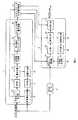
図1には本発明の第1の実施の形態に係る符号化装置の構成を示し説明する。(1) First Embodiment (1-1) Configuration of Encoding Device FIG. 1 shows and describes the configuration of an encoding device according to the first embodiment of the present invention.
この図1に示されるように、符号化装置は、MPEG−2に対応しており、プレコーダ1、パラメータエンコーダ2、マクロブロック符号量制御部3、ディレイバッファ4を備える。プレコーダ1は、予測モード決定部11、DCT(Discrete Cosine Transform)部12、量子化部13、逆量子化部14、IDCT(Inverse Discrete Cosine Transform)部15、動き予測と予測画生成部16、符号長計算部17、符号量のグルーピング部18、ピクチャ符号量予測部19からなる。そして、パラメータエンコーダ2は、予測モード選択部21、DCT部22、量子化部23、逆量子化部24、IDCT部25、予測画生成部26、符号化部27からなる。As shown in FIG. 1, the encoding apparatus is compatible with MPEG-2, and includes a
このような構成において、プレコーダ1はプレエンコード(Pre Encode)を行い、パラメータエンコーダ2は本エンコードを行うことになる。尚、プレコーダ1は例えば仮符号化部に相当し、パラメータエンコーダ2は例えば本符号化部に相当し、マクロブロック符号量制御部3は例えば符号量制御部に相当する。 In such a configuration, the
以下、図2及び図3のフローチャートを参照して、本発明の第1の実施の形態に係る画像処理装置としての符号化装置による符号化処理について詳述する。尚、以下の処理の全部又は一部は本発明の第1の実施の形態に係る画像処理方法としての画像符号化方法にも相当するものである。 Hereinafter, with reference to the flowcharts of FIGS. 2 and 3, the encoding process by the encoding apparatus as the image processing apparatus according to the first embodiment of the present invention will be described in detail. Note that all or part of the following processing corresponds to an image encoding method as the image processing method according to the first embodiment of the present invention.
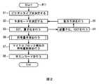
入力ビデオ信号には、予測モード決定部11でGOP(Group Of Pictures)周期を決定するNと、I又はPピクチャの周期を決定するための初期設定値Mとを基に、ピクチャタイプがIBBPBBP…のように周期的に割り振られる(ステップS1)。続いて、予測モード決定部11では、該入力ビデオ信号を受けて、マクロブロックのタイプを、予測画生成部16で求めたMC画との残差(MAD)とマクロブロックの分散等に基づいて、イントラMB(MB_Intra)、前方予測MB(MB_FW)、後方予測MB(MB_BW)、双方向M(MB_BI)等の中から予測モードが決定され、予測画像がDCT部12に送出される(ステップS2)。 The input video signal has a picture type of IBPBPBP based on N for determining the GOP (Group Of Pictures) period by the prediction
DCT部12では、予測画像が離散コサイン変換により周波数空間に変換され、DCT係数データが量子化部13に送出される。この量子化部13は、DCT係数データに対して固定的な固定量子化スケールQI(例えばq_scale=10)に基づく量子化ステップを用いて量子化処理を行う(ステップS3)。尚、この量子化スケールQは、量子化インデックスにより定められる。 In the
逆量子化部14、IDCT部15では、量子化部13の出力に基づいて予測画像を得るためにローカルデコード画像が生成される。即ち、逆量子化部14では、量子化部13から供給される量子化データが逆量子化されて、DCT係数データが再生される。IDCT部15では、このDCT係数データが逆離散コサイン変換されて、ローカルデコード画像が生成される。そして、このローカルデコード画像に基づいて、予測画生成部16により動き予測が行われることになる(ステップS4、S5)。 In the inverse quantization unit 14 and the
続いて、符号量予測が行われる(ステップS6)。より詳細には、図3のフローチャートに示されるように、量子化部13の出力(量子化データ)は、更に符号長計算部17にも送出され、実際に符号化するハフマンテーブルの符号長を基にMB発生符号量がマクロブロック毎に計数される(ステップS11)。符号量のグルーピング部18では、予測モード決定部11で求められたマクロブロックタイプ別の分類とMB発生符号量の上位ビット等を基に符号量が16〜32程度のグループに分類される(ステップS12)。このグルーピング(この例では16通り)したデータは、ピクチャ符号量予測部19に送出される。ピクチャ符号量予測部19では、統計的に求めた曲線(図4で後述する量子化スケールQとMB発生符号量の関係)を基にMB発生符号量を積算することでピクチャ当たりのピクチャ発生符号量を求める(ステップS13)。これに次いで、ピクチャのベースとなる平均量子化スケールQaを求め(ステップS14)、この平均量子化スケールQaを基に、マクロブロック毎の目標符号量TargetMBとマクロブロック単位での基本量子化スケールQMBを決定し(ステップS15)、図3の処理を終了する。Subsequently, code amount prediction is performed (step S6). More specifically, as shown in the flowchart of FIG. 3, the output (quantized data) of the quantizing
尚、アクティビティを考慮する場合には、後述する図4の遷移曲線の各曲線毎(すなわちグループ毎)に所定のオフセットを定義することで、ピクチャ毎の目標符号量TargetMBが求められる。When the activity is taken into consideration, the target code amount TargetMB for each picture is obtained by defining a predetermined offset for each curve (that is, for each group) of the transition curve of FIG. 4 described later.
さて、再び図1の説明に戻り、上述したようにマクロブロック符号量制御部3では、ピクチャの量子化スケールQが、符号量のグルーピング部18でグルーピングした情報と統計的に求めた遷移曲線に基づいて、マクロブロック毎の基本量子化スケールQMBとターゲットとなる目標符号量TargetMBに変換され、設定されることになる。Returning to the description of FIG. 1 again, as described above, in the macroblock code
パラメータエンコーダ2では、プレコーダ1で求めたピクチャタイプ、マクロブロックの予測モード、動きベクトル、ピクチャ符号量予測部19で決定した基本量子化スケールQMBと目標符号量TargetMBに基づいて、実際のMB発生符号量がフィードバックされ(ステップS7)ながら符号量制御が行われ、パラメータエンコードが行われる(ステップS8)。The
即ち、入力ビデオ信号がディレイバッファ4による遅延処理を経て入力される。予測モード選択部21では、マクロブロック符号量制御部3によりマクロブロックの予測モードが指示され、これに従って予測モードが選択される。DCT部22では離散コサイン変換がなされ、DCT係数データが量子化部23に送出される。量子化部23では、このDCT係数データに対してマクロブロック符号量制御部3で求められた基本量子化スケールQMBに基づく量子化ステップによる量子化がなされ、量子化データが符号化部27に送出される。この符号化部27では、可変長符号化がなされ、こうして符号化ストリームが出力される。尚、逆量子化部24、IDCT部25、予測画生成部26では、量子化部23の出力(量子化データ)に基づいて予測画像を得るためにローカルデコード画像が生成される。こうして、一連の処理を終了する。That is, the input video signal is input through the delay process by the
ここで、図4に、統計的に求めた遷移曲線(MB量子化値と発生量の関係)を示し説明する。この図4は、実画像から、取り得る量子化スケールQ(Q=1〜31)の全ての場合についてマクロブロック毎のMB発生符号量を求め、イントラ(Intra)のピクチャについてマクロブロックの発生量で13段階にグルーピングしてプロットしたものである。 Here, FIG. 4 shows and describes a statistically obtained transition curve (relationship between MB quantization value and generation amount). FIG. 4 shows the MB generation code amount for each macroblock for all possible quantization scales Q (Q = 1 to 31) from the actual image, and the macroblock generation amount for an intra picture. This is a grouped plot with 13 levels.
MPEG−2等では可変長符号化としてハフマンテーブルを固定的に使用しており、ゼロランと非ゼロ係数の組み合わせでマクロブロック単位に符号化する。量子化スケールQの値を大きくするにつれてゼロランは次第に増加していき、非ゼロ係数のレベルは減少していくため、量子化スケールQを大きくするにつれて、単調減少する。画像の異なるマクロブロックであっても、ある量子化スケールQの値で同程度の発生量であったマクロブロックは同程度の減少曲線を描く傾向が確認できた。しかるに、本実施の形態に係る符号化装置では、この特徴的な傾向に着目し、1回の仮の符号化結果(固定量子化スケールQI)を用いて、目標とする目標符号量TargetMBをMB発生符号量として求める点に特徴の一つがある。In MPEG-2 or the like, a Huffman table is fixedly used as variable length coding, and coding is performed in units of macroblocks by a combination of zero run and non-zero coefficients. The zero run gradually increases as the value of the quantization scale Q increases, and the level of the non-zero coefficient decreases. Therefore, as the quantization scale Q increases, the zero run decreases monotonously. Even in the case of macroblocks with different images, it was confirmed that the macroblocks having the same generation amount at a certain quantization scale Q tend to draw the same decrease curve. However, in the encoding apparatus according to the present embodiment, paying attention to this characteristic tendency, the target target code amount TargetMB is calculated using a temporary encoding result (fixed quantization scale QI). One of the features is that it is obtained as the MB generated code amount.
すなわち符号化装置は、MB発生符号量の異なる複数(ここでは13)の画像データを、全ての量子化スケールQを用いてそれぞれ量子化したときに得られる予測用量子化データのMB発生符号量を関係情報として例えば図示しないROM(Read Only Memory)に記憶しておく。これにより符号化装置は、選択された固定量子化スケールQIによるMB発生符号量に基づいて、当該MB発生符号量に最も近い予測用量子化データを選択し、当該選択された予測用量子化データにおけるMB発生符号量を各量子化スケールQにおけるMB発生符号量として予測することができる。 In other words, the encoding device uses the MB generation code amount of the prediction quantized data obtained when each of a plurality (13 in this case) of image data having different MB generation code amounts is quantized using all the quantization scales Q. Is stored as related information in a ROM (Read Only Memory) (not shown), for example. Accordingly, the encoding device selects the prediction quantization data closest to the MB generation code amount based on the MB generation code amount based on the selected fixed quantization scale QI, and the selected prediction quantization data. Can be predicted as the MB generated code amount in each quantization scale Q.
次に、プレコーダ1によるプレエンコードの特徴を更に詳述する。 Next, the characteristics of pre-encoding by the
先ず、ピクチャ符号量予測部19による符号量予測処理について詳述する。 First, the code amount prediction processing by the picture code amount prediction unit 19 will be described in detail.
第1の実施の形態に係る符号化装置では、プレコーダ1の固定量子化スケールQIでの量子化後の量子化データについて、実際に符号化に使用するハフマンテーブルの符号長を基に、マクロブロックの発生量を計算する。例えば、固定量子化スケールQI(Q=10)でのMB発生符号量が0〜512byte程度に収まるとするならば、上位の4bitでMB発生符号量を基に、16通りに分類する。この分類により図4における、どの曲線を使用してMB発生符号量を予測するかを決定する。先に図4に示したな遷移曲線はイントラのマクロブロックとインターのマクロブロックで異なるため、イントラMB(MB_Intra)、前方予測MB(MB_FW)、後方予測MB(MB_BW)、双方向MB(MB_BI)の予測モード等で個別に予測曲線を使用する。 In the encoding apparatus according to the first embodiment, the macroblock is quantized based on the code length of the Huffman table actually used for encoding the quantized data after the quantization at the fixed quantization scale QI of the
具体的にピクチャ符号量予測部19は、グループごとにグループ閾値範囲を記憶している。そしてピクチャ符号量予測部19は、固定量子化スケールQIにおけるマクロブロックのMB発生符号量がどのグループ範囲閾値にあるかを判別し、当該マクロブロックを対応するグループに分類する。 Specifically, the picture code amount prediction unit 19 stores a group threshold range for each group. Then, the picture code amount prediction unit 19 determines which group range threshold the MB generated code amount of the macroblock in the fixed quantization scale QI is, and classifies the macroblock into a corresponding group.
予測曲線はVirBit[mb_mode][q_scale][byte_group]のように表すことができる。 The prediction curve can be expressed as VirBit [mb_mode] [q_scale] [byte_group].
ここで、mb_modeはマクロブロックの予測モード(4モード)、q_scaleは1〜31までの量子化インデックスから選択された量子化スケールQの値、byte_groupはMB発生符号量で分類した16通りのグループである。 Here, mb_mode is the macroblock prediction mode (4 modes), q_scale is the value of the quantization scale Q selected from the
画面全体(ピクチャごと)である量子化スケールQ(q_scale)でのMB発生符号量GenBitPic(q_scale)は、次式のように31通りの量子化スケールQ(q_scale)の分だけ求めることができる。 The MB generated code amount GenBitPic (q_scale) at the quantization scale Q (q_scale), which is the entire screen (each picture), can be obtained by 31 quantization scales Q (q_scale) as shown in the following equation.

すなわちピクチャ符号量予測部19は、マクロブロックごとに予測モードmb_mode、固定量子化スケールQI及び当該固定量子化スケールQIにおけるMB発生符号量から分類されたグループbyte_group(予測曲線)を選択する。そしてピクチャ符号量予測部19は、当該グループbyte_groupに該当する選択された予測曲線が示す固定量子化スケールQI以外の量子化スケールQについてのMB発生符号量を、当該固定量子化スケールQI以外の量子化スケールQにおけるMB発生符号量として予測することができる。さらにピクチャ符号量予測部19は、当該固定量子化スケールQI以外の量子化スケールQのMB発生符号量をピクチャごとに積算することにより、ピクチャごとのピクチャ発生符号量を予測することができる。 That is, the picture code amount prediction unit 19 selects a group byte_group (prediction curve) classified from the prediction mode mb_mode, the fixed quantization scale QI, and the MB generated code amount in the fixed quantization scale QI for each macroblock. Then, the picture code amount prediction unit 19 sets the MB generated code amount for the quantization scale Q other than the fixed quantization scale QI indicated by the selected prediction curve corresponding to the group byte_group to the quantum other than the fixed quantization scale QI. It can be predicted as the MB generated code amount in the quantization scale Q. Furthermore, the picture code amount prediction unit 19 can predict the picture generation code amount for each picture by accumulating the MB generation code amount of the quantization scale Q other than the fixed quantization scale QI for each picture.
このときピクチャ符号量予測部19は、関係情報として、予測モードmb_modeとグループbyte_groupに相当する情報(すなわち予測モードmb_modeごとに全グループ(全ての予測量子化データ)に対応する量子化スケールQ及びMB発生符号量の関係を表す関係情報(予測曲線))を保持しておけば、予測曲線(遷移曲線)を基にマクロブロックの予測発生量を求めることができる。 At this time, the picture code amount prediction unit 19 uses information corresponding to the prediction mode mb_mode and the group byte_group (that is, the quantization scales Q and MB corresponding to all groups (all predicted quantized data) for each prediction mode mb_mode) as related information. If the relationship information (prediction curve) representing the relationship between the generated code amounts is held, the predicted generation amount of the macroblock can be obtained based on the prediction curve (transition curve).
次にピクチャ符号量予測部19によるActivityへの対応について詳述する。ピクチャ符号量予測部19にてMB発生符号量を基に振り分けたbyte_groupはマクロブロックのMB発生符号量の多い場合ほど複雑な画像情報を含んでいるとみなせる。 Next, the correspondence to Activity by the picture code amount prediction unit 19 will be described in detail. The byte_group assigned based on the MB generated code amount by the picture code amount predicting unit 19 can be considered to include more complex image information as the MB generated code amount of the macroblock increases.
複雑なブロックほど量子化スケールQを大きくするような処理はグループbyte_group毎にオフセットを付けることで実現できる。このアクティビティのオフセットをλ[q_scale][byte_group]とするならば、例えば、量子化スケールQ(例えばq_scale=15)については、±4程度のアクティビティをつけるとき、次式のようにしておけばよいことになる。 Processing that increases the quantization scale Q for more complex blocks can be realized by adding an offset for each group byte_group. If the offset of this activity is λ [q_scale] [byte_group], for example, for the quantization scale Q (for example, q_scale = 15), when an activity of about ± 4 is added, the following equation may be used. It will be.
すなわちピクチャ符号量予測部19は、量子化スケールQ及びグループbyte_groupごとにオフセットを設定している。ピクチャ符号量予測部19は、例えばMB発生符号量を予測する量子化スケールQ(q_scale)が「15」であり、MB発生符号量の小さいほうから3番目のグループに属する場合、(2)式における左から3番目の「−3」を量子化スケールQ(q_scale)の「15」に付加することになる。 That is, the picture code amount prediction unit 19 sets an offset for each quantization scale Q and group byte_group. For example, when the quantization scale Q (q_scale) for predicting the MB generated code amount is “15” and belongs to the third group from the smallest MB generated code amount, the picture code amount predicting unit 19 The third “−3” from the left is added to “15” of the quantization scale Q (q_scale).
一般に、量子化スケールQ(q_scale)の小さいときはアクティビティを使用する必要はないので、オフセットのレンジは量子化スケールQ(q_scale)で変化させるようにしておき、量子化スケールQ(q_scale)が大きくなる程、レンジを大きくする方が良い。 In general, when the quantization scale Q (q_scale) is small, there is no need to use an activity. Therefore, the offset range is changed by the quantization scale Q (q_scale), and the quantization scale Q (q_scale) is large. Indeed, it is better to increase the range.
このλを用いると、画面全体のピクチャ発生符号量GenBitPicの予測値は次式のようになる。 When this λ is used, the predicted value of the picture generation code amount GenBitPic of the entire screen is expressed by the following equation.
すなわちピクチャ符号量予測部19は、予測対象となる量子化スケールQ(ピクチャごとに固定)に対してアクティビティによるオフセットを付加した量子化スケールQに基づくピクチャ発生符号量を予測する。このときピクチャ符号量予測部19は、オフセットの付加及び予測曲線に基づくMB発生符号量の予測をマクロブロックごとに実行する。そしてピクチャ符号量予測部19は、MB発生符号量をピクチャごとに積算することにより、予測対象の量子化スケールQに基づくピクチャ発生符号量GenBitPicを予測することができる。 That is, the picture code amount prediction unit 19 predicts a picture generation code amount based on the quantization scale Q obtained by adding an offset due to activity to the quantization scale Q to be predicted (fixed for each picture). At this time, the picture code amount prediction unit 19 executes the addition of the offset and the prediction of the MB generated code amount based on the prediction curve for each macroblock. The picture code amount prediction unit 19 can predict the picture generation code amount GenBitPic based on the quantization scale Q to be predicted by accumulating the MB generation code amount for each picture.
ここで、(4)式におけるmin(a,b)はa,bのうち小さい値、max(c,d)はc,dのうち大きい値を示す。 Here, min (a, b) in equation (4) indicates a smaller value of a and b, and max (c, d) indicates a larger value of c and d.
すなわちピクチャ符号量予測部19は、予測対象となる量子化スケールQにオフセットが付加された結果「1」未満となる場合には、アクティビティによるオフセットを付加した量子化スケールQを「1」とする。またピクチャ符号量予測部19は、予測対象となる量子化スケールQにオフセットが付加された結果「31」を超える場合には、アクティビティによるオフセットを付加した量子化スケールQを「31」とする。言い換えるとピクチャ符号量予測部19は、アクティビティによるオフセットを付加した量子化スケールQを、量子化インデックスによって定められた「1〜31」の中から選択するようになされている。 That is, the picture code amount prediction unit 19 sets the quantization scale Q to which the offset by the activity is added to “1” when the result of adding the offset to the quantization scale Q to be predicted is less than “1”. . Further, when the result of adding the offset to the quantization scale Q to be predicted exceeds “31”, the picture code amount prediction unit 19 sets the quantization scale Q to which the offset due to the activity is added to “31”. In other words, the picture code amount prediction unit 19 selects the quantization scale Q to which the offset due to the activity is added, from “1 to 31” determined by the quantization index.
このようにピクチャ符号量予測部19は、画面全体の量子化スケールQ(q_scale_pic =1〜31)の全ての場合について、ピクチャ単位でのピクチャ発生符号量を求めることができ、目標とするピクチャ目標符号量に近い量子化スケールQ(q_scale_target)を平均量子化スケールQaとして導出する。 As described above, the picture code amount prediction unit 19 can obtain the picture generation code amount in units of pictures for all cases of the quantization scale Q (q_scale_pic = 1 to 31) of the entire screen. A quantization scale Q (q_scale_target) close to the code amount is derived as an average quantization scale Qa.
次に、マクロブロック符号量制御部3による量子化インデックス決定処理について詳述する。このマクロブロック符号量制御部3によるマクロブロック単位の符号量制御ではマクロブロックの基本量子化スケールQMBと目標とするマクロブロックのMB目標符号量TargetMBを、次式のように予測することができる。Next, the quantization index determination process by the macroblock code
すなわちマクロブロック符号量制御部3は、平均量子化スケールQaに対してアクティビティによるオフセットを付加することにより、基本量子化スケールQMBを決定する。That macroblock code
またマクロブロック符号量制御部3は、基本量子化スケールQMBにおいてマクロブロックごとに予測されるMB発生符号量を、MB目標符号量TargetMBとして予測する。The macroblock code
すなわち符号化装置は、MB発生符号量の相違する複数の予測用量子化データのMB発生符号量と、各量子化スケールQにおけるMB発生符号量との関係を予測曲線として記憶しておく。そして符号化装置は、固定量子化スケールQI及び当該固定量子化スケールQIにおけるMB発生符号量に基づいて、予測対象となるマクロブロックをグルーピングし、予測用量子化データに当て嵌める。そして符号化装置は、当該当て嵌められた予測用量子化データにおける固定量子化スケールQI以外の量子化スケールQにおけるMB発生符号量を、当該当て嵌められた予測用量子化データのMB発生符号量から予測する。 That is, the encoding apparatus stores, as a prediction curve, the relationship between the MB generated code amount of a plurality of prediction quantized data having different MB generated code amounts and the MB generated code amount at each quantization scale Q. Then, the encoding device groups the macroblocks to be predicted based on the fixed quantization scale QI and the MB generated code amount in the fixed quantization scale QI, and applies the macroblocks to the prediction quantization data. Then, the encoding apparatus uses the MB generation code amount of the fitted prediction quantization data as the MB generation code amount in the quantization scale Q other than the fixed quantization scale QI in the fitted prediction quantization data. Predict from.
すなわち符号化装置は、固定量子化スケールQIに基づく量子化ステップを用いた1回の符号化により、想定されている全ての量子化スケールQに基づく量子化ステップを用いたときのMB発生符号量を予測することができる。 In other words, the encoding apparatus performs MB encoding when the quantization steps based on all the assumed quantization scales Q are used by performing encoding once using the quantization steps based on the fixed quantization scale QI. Can be predicted.
そしてパラメータエンコーダ2による本エンコードでは、プレコーダ1で求めたピクチャタイプ、マクロブロックモード、動きベクトル、予測したマクロブロックの基本量子化スケールQMB を使用して、パラメータエンコードを行う。尚、マクロブロックのMB発生符号量の情報は、フィードバックし、前述したような符号量制御を行うことになる。In the main encoding by the
この結果符号化装置は、当該予測したMB発生符号量に基づいて画像に応じた適切な基本量子化スケールQMB及びMB目標符号量TargetMBを設定することができ、いわゆるフィードフォワードによる符号量制御を実行し得るようになされている。As a result, the encoding apparatus can set an appropriate basic quantization scale QMB and MB target code amount TargetMB according to the image based on the predicted MB generated code amount, and control the code amount by so-called feedforward. Has been made to be able to run.
以上説明したように、本発明の第1の実施の形態に係る符号化装置及び方法によれば、マクロブロック単位の基本量子化スケールQMB、MB目標符号量TargetMBの予測値を精度良く求めることができる。As described above, according to the coding apparatus and method according to the first embodiment of the present invention, the prediction values of the basic quantization scale QMB and the MB target code amount TargetMB for each macroblock are obtained with high accuracy. be able to.
(1−2)符号化処理手順
次に、符号化プログラムに従って実行される符号化処理について、図2及び図3のフローチャートを用いて説明する。(1-2) Encoding Process Procedure Next, an encoding process executed according to the encoding program will be described with reference to the flowcharts of FIGS.
符号化装置のプレコーダ1は、入力ビデオ信号が供給されると、符号化処理手順RT1を開始し、ステップS1において、GOP周期及びI,Pピクチャの周期を決定するための初期設定値Mを基に、ピクチャタイプを周期的に割り振ると、次のステップS2へ移る。 When the input video signal is supplied, the
ステップS2において、プレコーダ1は、入力ビデオ信号が表す符号化対象となる対象画像及び予測の対象となる予測画像から、最適な予測モード(mb_mode)を決定すると共に、当該最適な予測モードを用いた差分画像データSADを生成し、次のステップS3へ移る。 In step S2, the
ステップS3において、プレコーダ1は、差分画像データSADに対し、マクロブロック単位で整数精度DCTにより直交変換を行い、さらに固定量子化スケールQIを用いて量子化を実行することにより、量子化データを生成すると、次のステップS4及びステップS6へ移る。 In step S3, the
ステップS4において、プレコーダ1は、量子化データに対して逆量子化及びIDCTを実行し、ローカル差分画像データSADLを生成すると、次のステップS5へ移る。ステップS5において、プレコーダ1は、当該ローカル差分画像データSADLを予測画像とし、以降の対象画像に対するステップ2における処理を遂行させる。 In step S4, the
ステップS6において、プレコーダ1は、符号量予測処理手順RT2(図3)のステップS11へ移る。 In step S6, the
ステップS11において、プレコーダ1は、符号長計算部17によって量子化データを符号化し、仮の量子化データとして符号化ストリームを生成することにより、固定量子化スケールQIでのマクロブロックごとのMB発生符号量(すなわち仮の量子化データのMB発生符号量)を計算すると、次のステップS12へ移る。 In step S11, the
ステップS12において、プレコーダ1は、符号量のグルーピング部18により、ステップS2において決定された予測モード及びステップ11において算出されたMB発生符号量とに基づいて、複数記憶されている予測曲線(例えば予測モードごとに準備された各16の曲線)の中から、一の予測曲線(グループ)に予測対象となるマクロブロックを割り当てると、次のステップS13へ移る。 In step S12, the
ステップS13において、プレコーダ1は、ピクチャ符号量予測部19により、全ての量子化スケールQ(q_scale)におけるMB発生符号量を、ピクチャごとに算出すると、次のステップS14へ移る。 In step S13, the
このときプレコーダ1は、各マクロブロックがどのグループに割り当てられたかに応じて、(2)式に示したように、量子化スケールQに対してアクティビティによるオフセットを増減した適応量子化スケールQt(act_q_scale)を算出する。プレコーダ1は、(3)式に示すように、適応量子化スケールQt(act_q_scale)を用いたときのマクロブロックごとのMB発生符号量を、割り当てられた予測曲線から算出する。 At this time, the
そしてプレコーダ1は、このマクロブロックごとのMB発生符号量をピクチャごとに積算することにより、ピクチャごとのピクチャ発生符号量を各量子化スケールQによるピクチャ発生符号量として算出する。 Then, the
ステップS14において、プレコーダ1は、ピクチャ目標符号量よりも小さく、かつ最も近いMB発生符号量でなる量子化スケールQを平均量子化スケールQa(q_scale_target)として選定すると、次のステップS15へ移る。 In step S14, the
ステップS15において、プレコーダ1は、(5)式に示したように、平均量子化スケールQaにおける適応量子化スケールQt(act_q_scale)を基本量子化スケールQMBとし、当該基本量子化スケールQMBにおけるマクロブロックごとのMB発生符号量を目標符号量TargetMBとすると、符号量予測処理手順RT2を終了して符号化処理手順RT1(図2)のステップS6へ戻り、次のステップS7へ移る。In step S15, the
ステップS7において、マクロブロック符号量制御部3は、基本量子化スケールQMB及びMB目標符号量TargetMBを用いた符号量制御により、パラメータエンコーダ2を制御しながら、ステップS8においてパラメータエンコーダ2に本エンコードを実行させることにより、本符号化ストリーム(すなわち本量子化データ)を生成すると、終了ステップへ移って処理を終了する。In step S7, the macroblock code
(1−3)動作及び効果
以上の構成によれば、符号化装置は、複数の量子化スケールQに基づく複数の量子化ステップのうち、選択された量子化スケールQIである固定量子化スケールQIに基づいて量子化単位であるマクロブロックごとに量子化ステップを選択し、当該選択された量子化ステップで画像データとしてのDCT係数データを量子化し、仮の量子化データを生成する。このとき符号化装置は、当該仮の量子化データのマクロブロック単位ごとの発生符号量をMB発生符号量として算出する。(1-3) Operation and Effect According to the configuration described above, the encoding device includes the fixed quantization scale QI that is the selected quantization scale QI among the plurality of quantization steps based on the plurality of quantization scales Q. Based on the above, a quantization step is selected for each macroblock which is a quantization unit, and DCT coefficient data as image data is quantized by the selected quantization step to generate temporary quantized data. At this time, the encoding apparatus calculates the generated code amount for each macroblock unit of the temporary quantized data as the MB generated code amount.
符号化装置は、固定量子化スケールQIに基づいて選択された量子化ステップにおいてMB発生符号量が相違する複数の予測用量子化データについて、複数の量子化ステップを表す複数の量子化スケールQとMB発生符号量との関係を表す関係情報を予測曲線として記憶している。 The encoding apparatus includes a plurality of quantization scales Q representing a plurality of quantization steps and a plurality of prediction quantization data having different MB generation code amounts in the quantization step selected based on the fixed quantization scale QI. Relation information representing the relation with the MB generated code amount is stored as a prediction curve.
符号化装置は、仮の量子化データのMB発生符号量及び固定量子化スケールQIに基づいて複数の予測曲線から予測用量子化データを選択し、当該選択された予測用量子化データに基づいて、複数の量子化スケールQのうち、固定量子化スケールQI以外の量子化スケールQに基づく量子化ステップ(すなわち選択されなかった量子化ステップ)によって画像データを量子化したときのMB発生符号量を予測する。 The encoding device selects prediction quantization data from a plurality of prediction curves based on the MB generation code amount of the temporary quantization data and the fixed quantization scale QI, and based on the selected prediction quantization data The MB generated code amount when the image data is quantized by a quantization step based on a quantization scale Q other than the fixed quantization scale QI among the plurality of quantization scales Q (ie, a quantization step not selected) Predict.
これにより符号化装置は、固定量子化スケールQIに基づいて選択された1つの量子化ステップにおいて予測対象となるDCT係数データを量子化するだけで、複数の量子化スケールQに基づく複数の量子化ステップにより当該対象となるDCT係数データを量子化したときのMB発生符号量を予測することができる。この結果符号化装置は、複数の量子化スケールQにおいてDCT係数データを量子化する従来の方法と比較して、処理負荷を軽減して構成を簡易にすることができる。 As a result, the encoding apparatus simply quantizes the DCT coefficient data to be predicted in one quantization step selected based on the fixed quantization scale QI, and performs a plurality of quantizations based on the plurality of quantization scales Q. By the step, it is possible to predict the MB generated code amount when the target DCT coefficient data is quantized. As a result, the encoding apparatus can reduce the processing load and simplify the configuration as compared with the conventional method of quantizing DCT coefficient data in a plurality of quantization scales Q.
また符号化装置は、予測したMB発生符号量を積算することにより、符号化単位であるピクチャごとの量子化データの発生符号量であるピクチャ発生符号量GenBitPicを予測する。これにより符号化装置は、予測したMB発生符号量を積算するだけの簡易な処理によりピクチャ発生符号量GenBitPicを予測することができる。 Further, the encoding apparatus predicts a picture generation code amount GenBitPic, which is a generation code amount of quantized data for each picture, which is an encoding unit, by accumulating the predicted MB generation code amount. As a result, the encoding apparatus can predict the picture generation code amount GenBitPic by a simple process of adding up the predicted MB generation code amount.
さらに符号化装置は、複数の量子化スケールQに基づく複数の量子化ステップのうち、ピクチャ発生符号量GenBitPicがピクチャごとの目標となるピクチャ目標符号量に近づくよう基本量子化ステップQMBを予測する。Further, the encoding apparatus predicts the basic quantization step QMB so that the picture generation code amount GenBitPic approaches the target picture target code amount for each picture among the plurality of quantization steps based on the plurality of quantization scales Q. .
ここで上記TM5に代表される従来のフィードバック型の符号量制御では、基本量子化スケールQMBによって発生する実際のMB発生符号量が全くの未知であるため、MB目標符号量と実際のMB発生符号量とが大きく相違する場合がある。このため従来の符号量制御では、例えばマクロブロックごとに異なるシーケンスに切り替わる際には、切り替わる前の基本量子化スケールに応じて不適切な基本量子化スケールが設定される場合があった。このような場合、従来の符号量制御では、シーケンス突入時に符号量を発生しすぎてしまい、ピクチャ後半において符号量を抑える必要が生じ、画面下部が上部よりも歪が大きくなり、画質の劣化が目立ってしまっていた。Here, in the conventional feedback type code amount control represented by TM5, since the actual MB generated code amount generated by the basic quantization scale QMB is completely unknown, the MB target code amount and the actual MB generation There is a case where the code amount greatly differs. For this reason, in the conventional code amount control, for example, when switching to a different sequence for each macroblock, an inappropriate basic quantization scale may be set according to the basic quantization scale before switching. In such a case, in the conventional code amount control, the code amount is excessively generated at the time of entering the sequence, so that it is necessary to suppress the code amount in the second half of the picture, the distortion in the lower part of the screen is larger than the upper part, and the image quality is deteriorated. It was conspicuous.
これに対して符号化装置は、ピクチャが表す画像に応じた適切な基本量子化ステップQMBを設定することができ、実際のピクチャ発生符号量GenBitPicをピクチャ目標符号量に近づけることができ、かかる画質の劣化を抑制することができる。On the other hand, the encoding apparatus can set an appropriate basic quantization step QMB according to the image represented by the picture, and can bring the actual picture generation code amount GenBitPic closer to the picture target code amount. Degradation of image quality can be suppressed.
また符号化装置は、マクロブロック単位ごとにDCT係数データを量子化して本量子化データを生成する。このとき符号化装置は、本量子化データのピクチャ発生符号量GenBitPicがピクチャ目標符号量に近づくよう、基本量子化ステップQMBから変動させた変動量子化ステップでDCT係数データを量子化させる。The encoding device also quantizes the DCT coefficient data for each macroblock unit to generate the main quantized data. In this case the coding apparatus, the picture generated code amount GenBitPic of the quantized data to approach to the picture target code amount, thereby quantizing the DCT coefficient data at a variable quantization step is varied from the basic quantization step QMB.
これにより符号化装置は、本符号化において実際に発生する符号量に基づき基本量子化ステップQMBを適宜変更することができるため、本量子化データのピクチャ発生符号量GenBitPicをピクチャ目標符号量に近づけることができる。As a result, the encoding apparatus can appropriately change the basic quantization step QMB based on the code amount actually generated in the main encoding, and therefore the picture generation code amount GenBitPic of the quantized data is set to the picture target code amount. You can get closer.
さらに符号化装置は、本量子化データのMB発生符号量とマクロブロック単位ごとのMB発生符号量の目標となるMB目標符号量TargetMBとの符号量の差分に基づいて基本量子化スケールQMBから変動させた変動量子化スケールQSMBによる変動量子化ステップを決定する。Furthermore, the encoding device uses the basic quantization scale QMB based on the difference in code amount between the MB generated code amount of the present quantized data and the MB target code amount TargetMB that is the target of the MB generated code amount for each macroblock unit. The variation quantization step based on the variation quantization scale QSMB varied from the above is determined.
これにより符号化装置は、本量子化データのMB発生符号量とMB目標符号量TargetMBとの差分に基づくフィードバック制御により、基本量子化ステップQMBを適宜変更することができる。このため符号化装置は、符号量の不足に起因するピクチャ全体における部分的な画質劣化を引き起こすことなく、適切にDCT係数データを量子化することができる。Thus, the encoding apparatus can appropriately change the basic quantization step QMB by feedback control based on the difference between the MB generated code amount of the present quantized data and the MB target code amount TargetMB . For this reason, the encoding apparatus can appropriately quantize the DCT coefficient data without causing partial image quality degradation in the entire picture due to a lack of code amount.
また符号化装置は、予測された基本量子化スケールQMBに基づいて予測したMB発生符号量を、MB目標符号量TargetMBとする。Also, the encoding apparatus sets the MB generated code amount predicted based on the predicted basic quantization scale QMB as the MB target code amount TargetMB .
これにより符号化装置は、基本量子化スケールQMBを決定するためのピクチャ発生符号量GenBitPicの予測のために算出されたMB目標符号量TargetMBをそのままMB目標符号量TargetMBとして用いることができるため、処理負荷を軽減することができる。Thus the encoding device can be used as it is as MB target code amount TargetMB and MB target code amount TargetMB calculated for prediction picture generated code amount GenBitPic for determining the basic quantization scale QMB Therefore, the processing load can be reduced.
さらに符号化装置は、ピクチャ発生符号量GenBitPicがピクチャ目標符号量よりも小さく、かつピクチャ発生符号量GenBitPic及びピクチャ目標符号量の差分が最小となる平均量子化ステップQaを選択し、当該平均量子化ステップQaに対してアクティビティ増減値としてのオフセットλを加減することにより、基本量子化ステップQMBを予測する。Further, the encoding device selects an average quantization step Qa in which the picture generation code amount GenBitPic is smaller than the picture target code amount and the difference between the picture generation code amount GenBitPic and the picture target code amount is minimized, and the average quantization step The basic quantization step QMB is predicted by adding or subtracting the offset λ as the activity increase / decrease value to the step Qa.
これにより符号化装置は、画像の複雑さに応じて基本量子化ステップQMBを変動させることができ、複雑な画像に対する誤差を認識しづらいという人間の視覚特性を利用して、量子化によって発生する誤差を視覚的に目立ちにくくすることができる。As a result, the encoding device can vary the basic quantization step QMB according to the complexity of the image, and is generated by quantization using the human visual characteristic that it is difficult to recognize an error for a complex image. It is possible to make the error to be visually inconspicuous.
また符号化装置は、予測用量子化データ(すなわちグループ)に応じたオフセットλを平均量子化ステップQaに対して加算する。これにより符号化装置は、グループに応じて単純にオフセットλを加算するだけで済み、例えばDCT係数データにおける分散を算出などの適応量子化のための処理をわざわざ実行する必要がなく、処理を簡易にすることができる。 Also, the encoding device adds an offset λ corresponding to the prediction quantized data (that is, the group) to the average quantization step Qa. As a result, the encoding apparatus simply needs to add the offset λ according to the group, and does not need to bother to execute a process for adaptive quantization such as calculation of variance in DCT coefficient data. Can be.
これにより符号化装置は、固定量子化スケールQIに基づく量子化ステップ(すなわち選択された量子化ステップ)によりピクチャ単位のDCT係数データを量子化する。これにより符号化装置は、ピクチャ発生符号量GenBitPicを算出する際に適応量子化をしなくて済み、処理を簡易にすることができる。 Accordingly, the encoding apparatus quantizes the DCT coefficient data in units of pictures by a quantization step based on the fixed quantization scale QI (that is, the selected quantization step). Thereby, the encoding apparatus does not need to perform adaptive quantization when calculating the picture generation code amount GenBitPic, and can simplify the processing.
さらに符号化装置は、ピクチャタイプ(すなわち予測モードmb_mode)ごとに関係情報(すなわち複数の予測用量子化データ)を記憶し、ピクチャタイプに応じた関係情報から予測用量子化データを選択する。 Further, the encoding apparatus stores relation information (that is, a plurality of prediction quantized data) for each picture type (that is, prediction mode mb_mode), and selects prediction quantized data from the relation information corresponding to the picture type.
これにより符号化装置は、ピクチャタイプに応じた関係情報を用いてMB発生符号量を予測できるため、予測の精度を向上させることができる。 As a result, the encoding apparatus can predict the MB generated code amount using the relationship information according to the picture type, and thus can improve the prediction accuracy.
また符号化装置は、DCT係数データを量子化した後に固定的なテーブルを用いた可変長符号化であるハフマン符号化をすることにより仮の量子化データを生成する。符号化装置は、選択された予測用量子化データにおける固定量子化スケールQI以外の量子化スケールQに基づく量子化ステップ(すなわち選択されなかった量子化ステップ)におけるMB発生符号量を、当該選択されなかった量子化ステップによってDCT係数データを量子化したときのMB発生符号量として予測する。 The encoding device generates temporary quantized data by performing Huffman encoding, which is variable length encoding using a fixed table, after quantizing the DCT coefficient data. The encoding device selects the MB generation code amount in the quantization step based on the quantization scale Q other than the fixed quantization scale QI in the selected prediction quantization data (that is, the quantization step not selected). It is predicted as the MB generation code amount when the DCT coefficient data is quantized by the quantization step that has not been performed.
これにより符号化装置は、量子化スケールQの値を大きくするにつれてゼロランは次第に増加していき、非ゼロ係数のレベルは減少していくため、量子化スケールQを大きくするにつれて、MB発生符号量が単調減少するという特性を利用して、高い精度でMB発生符号量を予測することができる。 As a result, the encoding apparatus gradually increases the zero run as the value of the quantization scale Q is increased, and the level of the non-zero coefficient is decreased. Therefore, as the quantization scale Q is increased, the MB generated code amount is increased. It is possible to predict the MB generated code amount with high accuracy by utilizing the characteristic that the monotone decreases.
さらに符号化装置は、入力される画像データとしてのビデオ入力信号に対して所定の直交変換処理であるDCT処理を施すことにより、画像データを生成することにより、符号化効率を向上させることができる。 Furthermore, the encoding apparatus can improve encoding efficiency by generating image data by performing DCT processing, which is predetermined orthogonal transformation processing, on a video input signal as input image data. .
符号化装置では、本エンコード時のフィードバックは符号量を制御するための保険的な処理である為、ピクチャ当たりの理想的な符号量配分を予測することができ、例えばVTRシステム等で使用するIntra Frame CBRの符号量制御を従来のように5段の並列処理を行うことなく実現できる。また、TM5等のフィードバック型の符号量制御で問題となる、シーケンスの変った場合の符号量の使い過ぎによる時間的な不均衡な歪などを低減できる。 In the encoding apparatus, since the feedback during the main encoding is an insurance process for controlling the code amount, an ideal code amount distribution per picture can be predicted. For example, an intra used for a VTR system or the like can be predicted. The code amount control of Frame CBR can be realized without performing 5-stage parallel processing as in the past. In addition, it is possible to reduce temporal imbalance distortion caused by excessive use of the code amount when the sequence changes, which is a problem in feedback-type code amount control such as TM5.
以上の構成によれば、符号化装置は、予めMB発生符号量の相違する複数の予測用量子化データについて、量子化スケールQとMB発生符号量との関係を記憶しておき、固定量子化スケールQIを用いて画像データを量子化したときのMB発生符号量から、最も近いMB発生符号量を示す予測用量子化データを選択する。符号化装置は、選択した予測用量子化データにおける固定量子化スケールQI以外の量子化スケールQにおけるMB発生符号量を、画像データを量子化したときの固定量子化スケールQI以外の量子化スケールQにおけるMB発生符号量と擬制することにより、画像データを固定量子化スケールQI以外の量子化スケールQによって量子化したときのMB発生符号量を予測するようにした。 According to the above configuration, the encoding apparatus stores in advance the relationship between the quantization scale Q and the MB generated code amount for a plurality of prediction quantized data having different MB generated code amounts, and performs fixed quantization. The prediction quantized data indicating the closest MB generated code amount is selected from the MB generated code amount when the image data is quantized using the scale QI. The encoding apparatus uses the quantization scale Q other than the fixed quantization scale QI when the image data is quantized, as the MB generated code amount in the quantization scale Q other than the fixed quantization scale QI in the selected prediction quantization data. By pretending to be the MB generated code amount in, the MB generated code amount when the image data is quantized with a quantization scale Q other than the fixed quantization scale QI is predicted.
これにより符号化装置は、固定量子化スケールQIに基づく選択された量子化ステップを用いて画像データを量子化するだけで固定量子化スケールQI以外の量子化スケールQに基づく量子化ステップ(すなわち選択されなかった量子化ステップ)によって当該画像データを量子化したときのMB発生符号量を予測することができる。かくして本発明は、固定の量子化ステップで計算した発生符号量から異なる量子化ステップにおける発生符号量を精度よく予測でき、演算を行うための回路を削減し得るよう、簡易な処理で異なる量子化ステップにおける発生符号量を予測し得る画像処理装置及び画像処理方法を実現できる。 As a result, the encoding apparatus simply quantizes the image data using the selected quantization step based on the fixed quantization scale QI, and the quantization step based on the quantization scale Q other than the fixed quantization scale QI (that is, the selection step). The MB generation code amount when the image data is quantized can be predicted by the quantization step that has not been performed. Thus, the present invention is able to accurately predict the generated code amount in different quantization steps from the generated code amount calculated in the fixed quantization step, and to reduce the number of circuits for performing the operation, so that different quantization can be performed with simple processing. An image processing apparatus and an image processing method that can predict the generated code amount in the step can be realized.
(2)第2の実施の形態
(2−1)符号化装置の構成
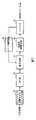
図5には従来技術に係る符号化装置の構成を示し説明する。(2) Second Embodiment (2-1) Configuration of Encoding Device FIG. 5 shows the configuration of an encoding device according to the prior art and will be described.
同図に示されるように、この符号化装置では、統計量算出部101で目標とする符号量の1フレーム分の割り当てビット量を計算し、DCT部102では離散コサイン変換を行いDCT係数データを量子化部103に送出する。量子化部103では、このDCT係数データを量子化スケールで量子化し量子化データを可変長符号化部104に送出する。可変長符号化部104では、量子化データを可変長符号化し、バッファ105に送出する。バッファ105は、送信データを一時記憶し、ビットストリームとして出力する。この処理の過程で、レート制御部106によるレート制御が行われる。即ち、仮想バッファ初期化部107により仮想バッファの初期化が行われ、仮想バッファ更新部108により仮想バッファの更新がなされ、量子化インデックス決定部109により量子化部103で採用する量子化スケールQを特定する。 As shown in the figure, in this encoding apparatus, a
しかるに、このような従来技術では、シーケンス先頭ピクチャやシーンチェンジ直後ピクチャのエンコードにおいては、仮想バッファが固定値となるために、エンコードするピクチャが当該固定値から大きく乖離するような絵柄の場合では、量子化スケールQのフィードバック制御により、画面上部から下部にかけて量子化スケールQが増加もしくは減少するため画質が劣化していた。また、この従来技術のような量子化スケールQのフィードバック制御を採用した場合には、マクロブロック毎にMB発生符号量と目標符号量の差分値を用いて次のマクロブロックの量子化スケールQを決定することになるが、マクロブロック目標符号量は常に一定であった為、画面上部が符号量小、画面下部が符号量大となる画像においては、画面上部に多くの符号量を割り当ててしまい、画面下部に割り当てる符号量が不足する為、マクロブロックスキップが発生することがあった。 However, in such a conventional technique, in the encoding of the sequence head picture or the picture immediately after the scene change, since the virtual buffer has a fixed value, in the case of a picture in which the picture to be encoded deviates greatly from the fixed value, Due to the feedback control of the quantization scale Q, the quantization scale Q increases or decreases from the upper part to the lower part of the screen, so that the image quality is deteriorated. Also, when the feedback control of the quantization scale Q as in this prior art is adopted, the quantization scale Q of the next macroblock is set using the difference value between the MB generated code amount and the target code amount for each macroblock. However, since the macroblock target code amount is always constant, a large amount of code is allocated to the upper part of the screen in an image where the upper part of the screen has a small code amount and the lower part of the screen has a large code amount. Because of the lack of code amount to be allocated at the bottom of the screen, macro block skip may occur.
このような問題に鑑みて、本発明の第2の実施の形態に係る符号化装置及び方法では、事前に固定量子化スケールQIでエンコードを行い、マクロブロック毎のMB発生符号量を利用して、ピクチャの平均量子化スケールavgQの予測とマクロブロックごとの目標符号量TargetMBの予測を行うことにより、ピクチャ内の量子化値分布が良好になるようなレート制御を行うことを特徴の一つとしている。以下、その構成及び作用効果を詳述する。In view of such a problem, in the encoding apparatus and method according to the second embodiment of the present invention, encoding is performed in advance with the fixed quantization scale QI, and the MB generated code amount for each macroblock is used. One feature is that rate control is performed such that the quantization value distribution in a picture is good by predicting the average quantization scale avgQ of the picture and predicting the target code amount TargetMB for each macroblock. It is said. Hereinafter, the structure and the effect are explained in full detail.
図6には本発明の第2の実施の形態に係る符号化装置の構成を示し説明する。 FIG. 6 shows and describes the configuration of an encoding apparatus according to the second embodiment of the present invention.
この図6に示されるように、この符号化装置は、MPEG−2に対応しており、1パス目のプレコーダ30、レート制御部40、2パス目のパラメータエンコーダ50からなる。 As shown in FIG. 6, this encoding apparatus corresponds to MPEG-2, and includes a
より詳細には、プレコーダ30は、統計量算出部31、DCT部32、量子化インデックス決定部33、量子化部34、可変長符号化部35、バッファ36からなる。レート制御部40は、仮想バッファ初期値の予測部41、仮想バッファ更新部42、量子化インデックス決定部43、マクロブロック目標符号量の予測部44からなる。そして、パラメータエンコーダ50は、量子化部51、可変長符号化部52、バッファ53からなる。 More specifically, the
このような構成において、レート制御部40では、マクロブロック単位のレート制御が実施される。そして、ピクチャ毎に2パス方式のエンコードを行う。即ち、プレコーダ30による1パス目は固定量子化スケールQIでエンコードを行いマクロブロック毎のMB発生符号量を収集する。パラメータエンコーダ50による2パス目は収集したMB発生符号量からピクチャの平均量子化スケールavgQを予測すると共にマクロブロック毎のMB目標符号量TargetMBを予測する。そして、これら予測値を用いて、レート制御手段としてのレート制御部が、例えばTM5のような量子化スケールフィードバックによるレート制御を行うものである。In such a configuration, the
尚、図6の構成では、2パス目のパラメータエンコーダ50にはDCT部等が備えられてないが、図7に示されるように、フォーマット変換マクロブロック化部91、DCT部92、量子化部51、可変長符号化部52、バッファ53で構成されているのと等価であり、この構成にレート制御部40が関与するようにすることもできる。 In the configuration of FIG. 6, the
以下、図8のフローチャートを参照して、第2の実施の形態に係る符号化装置による2パス方式エンコードでのレート制御について説明する。統計量算出部31は目標とする符号量の1フレーム分の割り当てビット量を計算する(ステップS21)。例えば、30フレーム/secの符号化を50Mbpsで行うとき、VTR等の1フレーム当たりの符号量を一定とするシステム等では、50Mbpsを1秒当たりのフレーム数「30」で除算した値(50Mbps/30)に基づいてピクチャ目標符号量pictBitsを算出する。 Hereinafter, with reference to the flowchart of FIG. 8, rate control in the two-pass encoding by the encoding apparatus according to the second embodiment will be described. The
ここで用いる目標符号量pictBitsは、次式により決定される。
Iピクチャのとき
pictBits = KI×Bitrate /(KI×NI + KP×NP + KB×NB )
Pピクチャのとき
pictBits = KP×Bitrate /(KI×NI + KP×NP + KB×NB )
Bピクチャのとき
pictBits = KB×Bitrate /(KI×NI + KP×NP + KB×NB )
KI = 5, KP = 3, KB = 1
Bitrate は 1秒辺りの発生符号量
NI、NP、NBはI、P、B ピクチャの1秒あたりの発生個数The target code amount pictBits used here is determined by the following equation.
For I picture
pictBits = KI x Bitrate / (KI x NI + KP x NP + KB x NB)
For P picture
pictBits = KP x Bitrate / (KI x NI + KP x NP + KB x NB)
For B picture
pictBits = KB x Bitrate / (KI x NI + KP x NP + KB x NB)
KI = 5, KP = 3, KB = 1
Bitrate is the amount of generated code per second
NI, NP, and NB are the number of I, P, and B pictures generated per second.
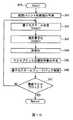
続いて、ピクチャ毎に1パス目のプレコーダ30により2回のエンコードを行う。即ち、1回目は量子化スケール固定値でエンコードしマクロブロック毎のMB発生符号量を収集し(ステップS22)、2回目は該MB発生符号量を用いて量子化スケールQの分布が適切になるようなレート制御をレート制御部40により行う(ステップS23)。こうして最終ピクチャであるか否かを判断し、上記処理を最終ピクチャとなるまで繰り返し(ステップS24)、最終ピクチャに到達すると、処理を終了することになる。 Subsequently, the encoding is performed twice by the pre-passer 30 in the first pass for each picture. That is, the first encoding is performed with the quantization scale fixed value and the MB generated code amount for each macroblock is collected (step S22). The second time, the quantization scale Q is appropriately distributed using the MB generated code amount. Such rate control is performed by the rate control unit 40 (step S23). In this way, it is determined whether or not it is the last picture, and the above process is repeated until the last picture is reached (step S24). When the last picture is reached, the process is terminated.
ここで、上記ステップS22の処理の詳細は図9のフローチャートに示される。 Here, the details of the process of step S22 are shown in the flowchart of FIG.
即ち、1回目のエンコードはMB発生符号量の収集を目的とするものであり、量子化スケールQを固定値である固定量子化スケールQIに設定し(ステップS31)、さらに視覚特性を利用した適応量子化を行い最終的な適応量子化スケールQtを決定する(ステップS32)。その適応量子化スケールQtを用いて量子化部34による量子化、及び可変長符号化部35による可変長符号化を行い(ステップS33)、そこで得られたMB発生符号量をマクロブロック毎にバッファ36に保存する(ステップS34)。以上の処理をマクロブロック毎に繰り返し(ステップS35)、最終マクロブロックに至ると、図7のステップS23以降の処理にリターンする。 That is, the first encoding is intended to collect the amount of MB generated codes, and the quantization scale Q is set to a fixed quantization scale QI that is a fixed value (step S31), and further adaptation using visual characteristics is performed. Quantization is performed to determine the final adaptive quantization scale Qt (step S32). Using the adaptive quantization scale Qt, quantization by the
次に、上記ステップS23の処理の詳細は図10のフローチャートに示される。 Next, details of the processing in step S23 are shown in the flowchart of FIG.
即ち、2回目のエンコードでは、MB発生符号量と量子化スケールQの相関関係を予め統計的に把握しておき、これを変換式(関係情報)として記憶している。そして当該変換式により1回目のピクチャ発生符号量からピクチャ目標符号量pictBitsに最も近いピクチャ発生符号量を発生させる量子化スケールを平均量子化スケールavgQとして予測する。この仮想バッファの初期値virtualBufは次式により決定される(ステップS41)。 That is, in the second encoding, the correlation between the MB generated code amount and the quantization scale Q is statistically grasped in advance and stored as a conversion formula (relation information). Based on the conversion formula, the quantization scale that generates the picture generation code quantity closest to the picture target code quantity pictBits from the first picture generation code quantity is predicted as the average quantization scale avgQ. The initial value virtualBuf of this virtual buffer is determined by the following equation (step S41).
ここで、virtualBufは仮想バッファの初期値、pictBitsはピクチャの目標符号量、avgQはピクチャの平均量子化スケールを意味している。 Here, virtualBuf is the initial value of the virtual buffer, pictBits is the target code amount of the picture, and avgQ is the average quantization scale of the picture.
すなわち仮想バッファの初期値は、平均量子化スケールavgQを「31」によって正規化した値とピクチャ目標符号量pictBitsとを乗算した値を「2」で除算することにより算出され、平均量子化スケールavgQ及びピクチャ目標符号量pictBitsに応じて変化することになる。 That is, the initial value of the virtual buffer is calculated by dividing the value obtained by normalizing the average quantization scale avgQ by “31” and the picture target code amount pictBits by “2”, and the average quantization scale avgQ And the picture target code amount pictBits changes.
仮想バッファが確定したら平均量子化スケールavgQを基本量子化スケールQMBとし、次式によりマクロブロック毎に変動量子化スケールQSMBを算出する(ステップS42)。When the virtual buffer is determined, the average quantization scale avgQ is set as the basic quantization scale QMB, and the variation quantization scale QSMB is calculated for each macroblock by the following equation (step S42).
QSMBはマクロブロックの変動量子化スケール、virtualBufMBはマクロブロック処理時点の仮想バッファ、pictsBitsはピクチャ目標符号量を意味している。QSMB represents a macroblock variation quantization scale, virtualBufMB represents a virtual buffer at the time of macroblock processing, and pictsBits represents a picture target code amount.
すなわち変動量子化スケールQSMBは、仮想バッファ現在値virtualBufMBをピクチャ目標符号量pictBitsによって除算した値に、「31」及び「2」を乗算することにより算出される。ここでピクチャ目標符号量pictBitsは同一ピクチャ内で固定であることから、変動量子化スケールQSMBは、仮想バッファ現在値virtualBufMBに応じて変動することになる。That is, the variation quantization scale QSMB is calculated by multiplying a value obtained by dividing the virtual buffer current value virtualBufMB by the picture target code amount pictBits by “31” and “2”. Here, since the picture target code amount pictBits is fixed in the same picture, the variation quantization scale QSMB varies according to the virtual buffer current value virtualBufMB .
ここで、TargetBitsMBはマクロブロックの目標符号量、pictBitsはピクチャ目標符号量、GenBitsMBは固定量子化スケールQIによるマクロブロックのMB発生符号量、numOfMBは1ピクチャのマクロブロック数である。Here, TargetBitsMB is the target code amount of the macroblock, pictBits is the target code amount of the picture, GenBitsMB is the MB generated code amount of the macroblock with the fixed quantization scale QI, and numOfMB is the number of macroblocks of one picture.
すなわちマクロブロックのMB目標符号量TargetMBは、固定量子化スケールQIによるMB発生符号量GenBitsMBの1ピクチャ分のMB発生符号量ΣGenBitsMBの合計値に対する割合をMB割合として算出し、当MB該割合に対してピクチャ目標符号量pictBitsを乗算して算出される。言い換えると、1ピクチャ分のMB発生符号量ΣGenBitsMBに拘らずMB割合が殆ど変化しないものとし、1ピクチャ分のMB発生符号量ΣGenBitsMBがピクチャ目標符号量pictBitsとなるときのマクロブロックのMB目標符号量TargetMBを算出している。That is, the MB target code amount TargetMB of the macroblock is calculated by calculating a ratio of the MB generated code amount GenBitsMB based on the fixed quantization scale QI to the total value of the MB generated code amount ΣGenBitsMB for one picture as the MB ratio. It is calculated by multiplying the ratio by the picture target code amount pictBits. In other words, it is assumed that the MB ratio hardly changes regardless of the MB generated code amount ΣGenBitsMB for one picture, and the MB target of the macroblock when the MB generated code amount ΣGenBitsMB for one picture becomes the picture target code amount pictBits. The code amount TargetMB is calculated.
こうして変動量子化スケールQSMBが決定したら1回目のエンコードと同じく量子化部34により適応量子化を行い(ステップS43)、可変長符号化部35により可変長符号化を実施する(ステップS44)。ピクチャ発生符号量をピクチャ目標符号量picBitsに近づけるために量子化スケールフィードバック制御を行うが、これは実際のMB発生符号量genBitsMBとMB目標符号量TargetMBとの差分に応じて基本量子化スケールQMBから増減された変動量子化スケールQSMBを用いることにより実現される。When the variation quantization scale QSMB is thus determined, adaptive quantization is performed by the
実際上仮想バッファ更新部42は、マクロブロック毎に実際のMB発生符号量genBitsMB−1と目標符号量TargetMBの差分を仮想バッファへ加算していく(ステップS46)。仮想バッファ現在値virtualBufMBは次式で求められる。なお1マクロブロック前のMB発生符号量genBitsMB−1を使用するのは、実際に符号化する際に遅延が生じるためである。In practice, the virtual
すなわち仮想バッファ現在値virtualBufMBは、実際のMB発生符号量genBitsMB−1と目標符号量TargetMBとの符号量の差異が小さければ殆ど変動せず、当該符号量の差異が大きければ大きく変動することになる。That is, the virtual buffer current value virtualBufMB hardly fluctuates if the difference in code amount between the actual MB generated code amount genBitsMB-1 and the target code amount TargetMB is small, and greatly fluctuates if the difference in code amount is large. It will be.
この結果、(8)式によって算出される変動量子化スケールQSMBの値は、実際のMB発生符号量genBitsMB−1とMB目標符号量TargetMBとの符号量の差異が小さければ当該基本量子化スケールQMB(平均量子化スケールQavg)から殆ど変動することなく決定される。一方、変動量子化スケールQSMBの値は、実際のMB発生符号量genBitsMB−1と目標符号量TargetMBとの符号量の差異が大きい場合には、仮想バッファ現在値virtualBufMBに応じて当該基本量子化スケールQMBから変動した値に決定されることになる。As a result, the value of the variation quantization scale QSMB calculated by the equation (8) is the basic quantum if the difference in code amount between the actual MB generated code amount genBitsMB-1 and the MB target code amount TargetMB is small. The quantization scale QMB (average quantization scale Qavg) is determined with little variation. On the other hand, when the difference between the actual MB generated code amount genBitsMB-1 and the target code amount TargetMB is large, the value of the fluctuation quantization scale QSMB is determined according to the virtual buffer current value virtualBufMB. The value is changed from the basic quantization scale QMB .
以上の処理をマクロブロック毎に繰り返す。即ち、最終マクロブロックに至ったか否かを判断し(ステップS47)、最終マクロブロックに至るまで上記処理を繰り返し、最終マクロブロックに至ると図8の処理にリターンすることになる。 The above processing is repeated for each macro block. That is, it is determined whether or not the final macroblock has been reached (step S47), and the above processing is repeated until the final macroblock is reached. When the final macroblock is reached, the processing returns to the processing of FIG.
以上説明したように、本発明の第2の実施の形態に係る符号化装置及び方法によれば、一つ前のピクチャの絵柄に関わらず量子化スケールの分布が良好なエンコードができ画質が向上する。さらに、当該ピクチャの絵柄に関わらずより正確なマクロブロック毎のレート配分を行うことができ画質が向上する。これにより、一部画像で符号量不足を原因とする画面下部マクロブロックスキップを防ぐことができる。 As described above, according to the coding apparatus and method according to the second embodiment of the present invention, encoding with a good quantization scale distribution can be performed regardless of the picture of the previous picture, and the image quality can be improved. To do. Further, more accurate rate allocation for each macroblock can be performed regardless of the picture pattern, and the image quality is improved. Thereby, it is possible to prevent the screen lower macroblock skip caused by the shortage of the code amount in some images.
(2−2)符号化処理手順
次に、符号化プログラムに従って実行される符号化処理について、図8〜図10のフローチャートを用いて説明する。(2-2) Encoding process procedure Next, the encoding process executed according to the encoding program will be described with reference to the flowcharts of FIGS.
符号化装置は、画像データとしてのビデオ入力信号が供給されると、符号化処理手順RT3を開始し、ステップS21においてプレコーダ30の統計量算出部31によってピクチャ目標符号量pictBitsを決定すると、次のステップS22に移る。 When a video input signal as image data is supplied, the encoding apparatus starts an encoding processing procedure RT3. When the picture target code amount pictBits is determined by the
ステップS22において、符号化装置は、プレコーダ30によって発生符号量を収集するために、固定量子化スケールQIを用いて画像データを符号化する符号量予測処理手順RT4(図9)のステップS31に移る。 In step S22, the encoding apparatus moves to step S31 of the code amount prediction processing procedure RT4 (FIG. 9) for encoding image data using the fixed quantization scale QI in order to collect the generated code amounts by the
ステップS22において、プレコーダ30は、DCT部32によって画像データに対してDCT処理を施すと共に、量子化インデックス決定部33によって固定量子化スケールQIを決定し、次のステップS32へ移る。In step S22, the
ステップS32において、プレコーダ30は、量子化部34によってDCT変換された画像データに対して、固定量子化スケールQIを用いて画像の複雑さに応じた適応量子化を行うと、次のステップS32へ移る。 In step S32, the
ステップS33において、プレコーダ30は、可変長符号化部35によって適応量子化が実行された画像データに対して可変長符号化を実行し、仮量子化データを生成すると、次のステップS34へ移る。ステップS34において、プレコーダ30は、当該仮量子化データのマクロブロックごとのMB発生符号量GenBitsMBをバッファ36に一時保存し、次のステップS35へ移る。In step S33, the
ステップS35において、プレコーダ30は、統計量算出部31によって処理対象となるマクロブロックが現在のピクチャにおける最終マクロブロックであるか否かを判別し、否定結果が得られた場合、ステップS32へ戻り、符号量予測処理を継続する。 In step S35, the
これに対してステップS35において肯定結果が得られた場合、このことは次のピクチャに対する符号量予測処理を実行すべきことを表しており、このときプレコーダ30は、符号化処理手順RT3のステップS22へ戻り、次のステップS23へ移る。 On the other hand, if a positive result is obtained in step S35, this indicates that the code amount prediction process for the next picture should be executed. At this time, the
ステップS23において、符号化装置は、ステップS22において算出されたMB発生符号量GenBitsMBを基にレート制御を実行しながら画像データを符号化する本符号化処理手順RT5(図10)のステップS41へ移る。In step S23, the encoding apparatus proceeds to step S41 of the encoding processing procedure RT5 (FIG. 10) for encoding image data while performing rate control based on the MB generated code amount GenBitsMB calculated in step S22. Move.
ステップS41において、符号化装置のレート制御部40は、ステップS22において算出されたMB発生符号量GenBitsMBを基に平均量子化スケールavgQを算出する。さらにレート制御部40は、仮想バッファ初期値の予測部41によって平均量子化スケールavgQを基に当該(7)式に従って仮想バッファの初期値virtualBufを算出し、これを仮想バッファ更新部42に設定すると、次のステップS42に移る。In step S41, the
ステップS42において、レート制御部40は、量子化インデックス決定部43により、平均量子化スケールavgQを基本量子化スケールQMBとし、(8)式に従い、仮想バッファ現在値virtualBufMBに応じて当該基本量子化スケールQMB(平均量子化スケールQavg)から変動した変動量子化スケールQSMBを決定すると、次のステップS43へ移る。In step S42, the
ステップS43において、レート制御部40は、量子化インデックス決定部43により、変動量子化スケールQSMBに基づき、画像データの複雑さ(アクティビティ)に応じた適応量子化スケールQStMBを決定する。そしてレート制御部40は、パラメータエンコーダ50の量子化部51に対し、当該適応量子化スケールQStMBを用いて量子化を実行するよう、当該量子化部51を制御すると、次のステップS44へ移る。In step S43, the
この結果量子化部51は、プレコーダ30のDCT部32から供給されるDCT処理された画像データ(DCT係数データ)を、当該適応量子化スケールQStMBを用いて量子化することになる。As a result, the
ステップS44において、パラメータエンコーダ50は、ステップS44において量子化された量子化データを、可変長符号化部52により、可変長符号化して仮量子化データとしての符号化ストリームを生成し、これをバッファ53に一時記憶し、次のステップS45へ移る。 In step S44, the
ステップS45において、レート制御部40は、ステップS21において決定されたピクチャ目標符号量pictBits及びバッファ36一時記憶されたMB発生符号量GenBitsMBを基に(9)式に従ってマクロブロックの次のマクロブロックに対するMB目標符号量TargetMBを算出すると、次のステップS46へ移る。In step S45, the
ステップS46において、レート制御部40は、仮想バッファ更新部42により次のMB目標符号量TargetMB及びステップS44においてバッファ53に一時記憶されたマクロブロックの実際のMB発生符号量genBitsMB−1に基づいて、(10)式に従って仮想バッファ現在値virtualBufMBを算出し、これを仮想バッファ更新部42に設定すると、次のステップ47へ移る。In step S46, the
この結果、MB目標符号量TargetMB及び実際のMB発生符号量genBitsMB−1の符号量の差異に基づいて逐次仮想バッファ現在値virtualBufMBが更新され、当該仮想バッファ現在値virtualBufMBを用いて算出される。
ステップS47において、レート制御部40は、処理対象となるマクロブロックが最終ブロックであるか否かを判別し、否定結果が得られた場合には、ステップS42へ戻り、本符号化処理を継続する。As a result, the virtual buffer current value virtualBufMB is sequentially updated based on the code amount difference between the MB target code amount TargetMB and the actual MB generated code amount genBitsMB−1 , and is calculated using the virtual buffer current value virtualBufMB. Is done.
In step S47, the
これに対してステップS47において肯定結果が得られた場合、このことは次のピクチャに対する処理を実行すべきことを表しており、このとき符号化装置は、符号化処理手順RT3(図8)のステップS23へ戻り、次のステップS24へ移る。 On the other hand, if an affirmative result is obtained in step S47, this indicates that the process for the next picture should be executed. At this time, the encoding apparatus performs the encoding process procedure RT3 (FIG. 8). It returns to step S23 and moves to the next step S24.
ステップS24において、符号化装置は、処理したピクチャが最終ピクチャであるか否かを判別し、否定結果が得られた場合には、ステップS22へ戻り、符号化処理を継続する。 In step S24, the encoding apparatus determines whether or not the processed picture is the final picture. If a negative result is obtained, the encoding apparatus returns to step S22 and continues the encoding process.
これに対してステップS24において否定結果が得られた場合、符号化装置は、終了ステップへ移って処理を符号化終了する。 On the other hand, when a negative result is obtained in step S24, the encoding apparatus moves to an end step and ends the encoding process.
(2−3)動作及び効果
以上の構成において、符号化装置は、(9)式に従って、選択された量子化ステップとして、固定量子化スケールQIに基づく量子化ステップ(すなわち量子化に使用された適応量子化スケールQtに基づく量子化ステップ)によるピクチャ発生符号量に対するピクチャ目標符号量pictBitの比率を、固定量子化スケールQIに基づくMB発生符号量GenBitsMBに対して乗算した値を、MB目標符号量TargetMBとする。(2-3) Operation and Effect In the above configuration, the encoding device uses the quantization step based on the fixed quantization scale QI (that is, used for quantization) as the selected quantization step according to the equation (9). MB target code is obtained by multiplying the ratio of the picture target code amount pictBit to the picture generated code amount by the quantization step based on the adaptive quantization scale Qt) to the MB generated code amount GenBitsMB based on the fixed quantization scale QI. Amount TargetMB .
ここで量子化スケールQが変化した場合、全体的な符号量は変動するものの、ピクチャ全体においてマクロブロックが実際に占有する符号量の割合はさほど変動しないと考えられる。 Here, when the quantization scale Q changes, although the overall code amount varies, it is considered that the ratio of the code amount actually occupied by the macroblock in the entire picture does not vary so much.
このため符号化装置は、固定量子化スケールQIに基づくMB発生符号量GenBitsMBから当該MB発生符号量GenBitsMBが当該固定量子化スケールQIにおけるピクチャ発生符号量に占める割合を算出する。そして符号化装置は、ピクチャ目標符号量pictBitに対する固定量子化スケールQIにおけるピクチャ発生符号量の比率を当該割合に乗算して符号量のスケールを調整することにより、MB目標符号量TargetMBを算出する。For this reason, the encoding apparatus calculates the ratio of the MB generated code amount GenBitsMB to the picture generated code amount in the fixed quantization scale QI from the MB generated code amount GenBitsMB based on the fixed quantization scale QI. Then, the encoding apparatus calculates the MB target code amount TargetMB by adjusting the scale of the code amount by multiplying the ratio by the ratio of the picture generation code amount in the fixed quantization scale QI with respect to the picture target code amount pictBit. .
これにより符号化装置は、画像データに応じた適切なMB目標符号量TargetMBに基づくフィードバック制御を実行することができるため、画像の種類やシーケンスの切り替りなどであっても、MB目標符号量TargetMBと実際のMB発生符号量genBitsMBとの符号量の差異を小さくすることができる。この結果符号化装置は、ピクチャの後方で割り当てる符号量が不足するような事態を未然に防止することができる。As a result, the encoding apparatus can execute feedback control based on the appropriate MB target code amount TargetMB according to the image data, so that the MB target code amount can be changed even when the image type or sequence is switched. The difference in code amount between the TargetMB and the actual MB generated code amount genBitsMB can be reduced. As a result, the encoding apparatus can prevent a situation in which the amount of code allocated behind the picture is insufficient.
また符号化装置は、プレコーダ30により、固定量子化スケールQIを用いて適応量子化を行うことにより、マクロブロックごとの画像データに応じて、量子化スケールQに基づく量子化ステップ(すなわち適応量子化スケールQtに基づく量子化ステップ)を選択し、当該選択された量子化ステップにより画像データを量子化する。 In addition, the encoding apparatus performs adaptive quantization using the fixed quantization scale QI by the
これにより符号化装置は、MB発生符号量GenBitsMBを単純に積算することにより、適応量子化を行った後のピクチャ発生符号量を算出することができる。Thus, the encoding apparatus can calculate the picture generation code amount after performing adaptive quantization by simply accumulating the MB generation code amount GenBitsMB .
さらに符号化装置は、パラメータエンコーダ50により、平均量子化スケールQavgをそのまま基本量子化スケールQMBとして使用すると共に、当該平均量子化スケールQavgから(7)式及び(8)式に従って算出された変動量子化スケールQSMBに基づいて適応量子化を実行するようにした。これにより符号化装置は、適応量子化により量子化歪みを目立ちにくくすることができる。Variation further coding apparatus, the
以上の構成によれば、符号化装置は、固定量子化スケールQIによるMB発生符号量GenBitsMBに基づいて、関係情報から基本量子化スケールQMBを決定すると共に、当該MB発生符号量GenBitsMBのピクチャに占める符号量の割合に基づいてMB目標符号量TargetMBを決定するようにした。According to the above configuration, the encoding apparatus determines the basic quantization scale QMB from the relationship information based on the MB generated code amount GenBitsMB based on the fixed quantization scale QI, and also determines the MB generated code amount GenBitsMB . The MB target code amount TargetMB is determined based on the ratio of the code amount in the picture.
これにより符号化装置は、画像データに応じた適切な基本量子化スケールQMB及びMB目標符号量TargetMBを設定することができるため、ピクチャ目標符号量pictBitに従ってピクチャ全体を適切に符号化することができる。As a result, the encoding device can set the appropriate basic quantization scale QMB and MB target code amount TargetMB according to the image data, and accordingly can appropriately encode the entire picture according to the picture target code amount pictBit. Can do.
(3)第3の実施の形態
(3−1)符号化装置の構成
以上説明した第2の実施の形態に係る符号化装置は、以下に示すように変形することもできる。この第3の実施の形態では、2パス符号量予測方式は、予想曲線から求めたマクロブロック毎の量子化スケールQ(q_scale)とMB発生符号量を使用し、スライス単位でのフィードバック制御を実行する。(3) Third Embodiment (3-1) Configuration of Encoding Device The encoding device according to the second embodiment described above can be modified as shown below. In the third embodiment, the 2-pass code amount prediction method uses the quantization scale Q (q_scale) and MB generation code amount for each macroblock obtained from the prediction curve, and performs feedback control in units of slices. To do.
図11には第3の実施の形態における符号化装置の構成を示し説明する。この図11に示されるように、この符号化装置は、1パス目のプレコーダ60、レート制御部70、2パス目のパラメータエンコーダ80からなる。 FIG. 11 shows the configuration of the encoding apparatus according to the third embodiment and will be described. As shown in FIG. 11, the encoding apparatus includes a
より詳細には、プレコーダ60は、統計量算出部61、DCT部62、固定Q量子化部63、可変長符号量計算部64、統計量算出部65からなる。レート制御部70は、量子化インデックス予測部71、量子化インデックス補正部72、スライス毎にターゲットビット量積算部73、ピクチャ毎に発生ビット量積算部74からなる。2パス目のパラメータエンコーダ80は、量子化部81、可変長符号化部82、バッファ83からなる。 More specifically, the
以下、図12及び図13のフローチャートを参照して、この変形例による符号化処理について詳細に説明する。メインフローは、図8と同様である。 Hereinafter, the encoding process according to this modification will be described in detail with reference to the flowcharts of FIGS. 12 and 13. The main flow is the same as in FIG.
まず、図12のピクチャ符号化(MB発生符号量収集)処理では、固定Q量子化部63で用いる量子化スケールに固定値を設定し(ステップS51)、この固定量子化スケールでDCT部62によるDCT後のDCT係数データを固定Q量子化部63で量子化し、可変長符号量計算部64で可変長符号量を計算し(ステップS52)、マクロブロック毎のMB発生符号量を求める(ステップS53)。このような処理を1ピクチャ分繰り返し、最終マクロブロックまで処理がなされたか否かを判断し(ステップS54)、処理が最終マクロブロックまでなされるとリターンする。 First, in the picture coding (MB generation code amount collection) processing of FIG. 12, a fixed value is set to the quantization scale used in the fixed Q quantization unit 63 (step S51), and the
次に、図13に示される処理では、統計量算出部65において、関係情報としての統計データVirBitを用いて、第1の実施の形態と同様に、ピクチャ目標発生量に近い量子化スケールQ(q_scale_target)を平均量子化スケールQaとして決定(ステップS61)する。また平均量子化スケールQaをベースとした適応量子化により、(5)式に従ってマクロブロックの基本量子化スケールQMB(q_scaleMB)を決定する(ステップS62)。このときのMB発生符号量TargetMBは、(6)式によって表される。Next, in the process shown in FIG. 13, the
ところでフィードバックの単位である1つのマクロブロック内にエッジ境界など8x8DCTブロックの特性の著しく異なる個所を有する場合などでは、特性の異なるグループの特性が加算されてしまい、グルーピングの単位がマクロブロックでは適切でない個所である。 By the way, when there is a part where the characteristics of the 8x8DCT block are remarkably different in one macroblock which is the unit of feedback, the characteristics of the groups with different characteristics are added, and the grouping unit is not appropriate for the macroblock. It is a place.
このような、統計的な曲線から外れるようなマクロブロックの暴れの影響を取り除くために、マクロブロックよりも大きな単位で、フィードバック制御を行うことができる。システムで許容できる実際に発生する実発生符号量の誤差の許容範囲で、例えば1ライン分のマクロブロックから1画面分までなどの単位で、行えばよい。 In order to eliminate the influence of the macroblock rampage that deviates from the statistical curve, feedback control can be performed in units larger than the macroblock. What is necessary is to carry out by the unit of the macro block for one line to the one screen, for example, within the allowable range of the actually generated code amount that is allowed in the system.
このフィードバックの単位をスライス(Slice)と以下では称することにする。 This unit of feedback will be referred to as a slice below.
1sliceの本符号化の終了する都度、実MB発生符号量genBitMB及びMB目標符号量TargetMBをそれぞれ積算することにより、スライスごとの実際の発生符号量であるスライス実発生符号量GenBitssliceとスライスごとの目標符号量であるスライス目標符号量Targetsliceを計算しておく(ステップS65、S66)。次のスライスに対応する全マクロブロックの基本量子化スケールQMB(q_scale)について変動値q_adjだけ補正する(ステップS65)ことでスライス単位のフィードバック制御を行う。Each time the actual encoding of 1 slice is completed, the actual MB generated code amount genBitMB and the MB target code amount TargetMB are integrated to obtain the slice actual generated code amount GenBitsslice, which is the actual generated code amount for each slice, and for each slice. The slice target code amount Targetslice, which is the target code amount, is calculated (steps S65 and S66). Feedback control in units of slices is performed by correcting the basic quantization scale QMB (q_scale) of all macroblocks corresponding to the next slice by the variation value q_adj (step S65).
ここで、TargetBitssliceはスライス分のMB目標符号量TargetMBの積算値、GenBitssliceはスライス分の実MB発生符号量である。Here, TargetBitsslice is the integrated value of the MB target code amount TargetMB for the slice, and GenBitsslice is the actual MB generated code amount for the slice.
ここで、変動値q_adjは次に符号化するスライス内の各基本量子化スケール(q_scale)に対して加算する。Deltasliceは基本量子化スケールQMB(q_scale)の1変化量相当の境界値であり、Σは先頭スライスからの和を意味している。Here, the variation value q_adj is added to each basic quantization scale (q_scale) in the slice to be encoded next. Deltaslice is a boundary value corresponding to one change amount of the basic quantization scale QMB (q_scale), and Σ means the sum from the first slice.
すなわち仮に変動値q_adjが大きく設定されすぎると、変動量子化スケールQSMB(q_scale_adj)の基本量子化スケールQMBからの変動が大きくなりすぎ、発散してしまう可能性がある。従ってスライス実発生符号量GenBitssliceとスライスごとの目標符号量であるスライス目標符号量Targetsliceとの符号量の差をΣDeltasliceで除算することにより、変動値q_adjを適正な値に調整するようになされている。That is, if the variation value q_adj is set too large, the variation of the variation quantization scale QSMB (q_scale_adj) from the basic quantization scale QMB may become too large and diverge. Therefore, the variation value q_adj is adjusted to an appropriate value by dividing the difference in code amount between the actual slice generated code amount GenBitsslice and the slice target code amount Targetslice, which is the target code amount for each slice, by ΣDeltaslice. .
次のスライスに対して変動値q_adjを補正後の変動量子化スケールQSMB(q_scale_adj)は「q_scale+q_adj」すなわち基本量子化スケールQMBに対して変動値q_adjとして表すことができる。そして当該変動量子化スケールQSMB(q_scale_adj)を用いて実符号化を行う(ステップS64)。以上の処理を、最後のスライスまで繰り返し(ステップS67)、最後のスライスまで処理を行うとリターンする。The variation quantization scale QSMB (q_scale_adj) after correcting the variation value q_adj for the next slice can be expressed as “q_scale + q_adj”, that is, the variation value q_adj with respect to the basic quantization scale QMB . Then, actual encoding is performed using the variation quantization scale QSMB (q_scale_adj) (step S64). The above processing is repeated until the last slice (step S67), and the processing returns to the last slice.
(3−2)符号化処理手順
次に、符号化プログラムに従って実行される符号化処理手順について、図12及び図13のフローチャートを用いて説明する。なお図12のフローチャートは、符号化処理手順RT3(図8)におけるステップS22において実行される符号量予測処理を表し、図13のフローチャートは、符号化処理手順RT3(図8)におけるステップS23において実行される本符号化処理を表している。(3-2) Encoding Process Procedure Next, an encoding process procedure executed according to the encoding program will be described with reference to the flowcharts of FIGS. 12 and 13. 12 represents the code amount prediction process executed in step S22 in the encoding process procedure RT3 (FIG. 8), and the flowchart in FIG. 13 is executed in step S23 in the encoding process procedure RT3 (FIG. 8). This encoding process is shown.
ステップS22において、符号化装置は、プレコーダ60によって発生符号量を収集するために、固定量子化スケールQIを用いて画像データを符号化する符号量予測処理手順RT6(図12)のステップS51に移る。 In step S22, the encoding apparatus moves to step S51 of a code amount prediction processing procedure RT6 (FIG. 12) for encoding image data using the fixed quantization scale QI in order to collect the generated code amounts by the
ステップS51において、プレコーダ60は、入力データに対してDCT部62によってDCT処理を施すと共に、当該DCT変換された画像データ(DCT係数データ)に対して、固定量子化スケールQIを用いて量子化を行い、仮量子化データを生成する。さらにプレコーダ60は、仮量子化データに対し、可変長符号量計算部64によって可変長符号化を行うことにより、仮の量子化データとして符号化ストリームを生成すると、次のステップS53へ移る。 In step S51, the
ステップS53において、プレコーダ60は、当該符号化ストリームのマクロブロックごとのMB発生符号量GenBitsMBを統計量算出部に一時保存し、次のステップS54へ移る。In step S53, the
ステップS54において、プレコーダ60は、統計量算出部31によって処理対象となるマクロブロックが現在のピクチャにおける最終マクロブロックであるか否かを判別し、否定結果が得られた場合、ステップS52へ戻り、符号量予測処理を継続する。 In step S54, the
これに対してステップS54において肯定結果が得られた場合、このことは次のピクチャに対する符号量予測処理を実行すべきことを表しており、このときプレコーダ60は、符号化処理手順RT3(図8)のステップS22へ戻り、次のステップS23へ移る。 On the other hand, if a positive result is obtained in step S54, this indicates that the code amount prediction process for the next picture should be executed. At this time, the
ステップS23において、符号化装置は、ステップS22において算出されたMB発生符号量GenBitsMBを基にレート制御を実行しながら画像データ(DCT係数データ)を符号化する本符号化処理手順RT7(図13)のステップS61へ移る。In step S23, the encoding apparatus performs an encoding process procedure RT7 (FIG. 13) for encoding image data (DCT coefficient data) while performing rate control based on the MB generated code amount GenBitsMB calculated in step S22. ) To Step S61.
ステップS61において、符号化装置のレート制御部70は、量子化インデックス予測部71により、ステップS22において算出されたMB発生符号量GenBitsMBを基に、ピクチャごとに決定される平均量子化スケールQaを算出すると、次のステップS62へ移る。In step S61, the
ステップS62において、レート制御部70は、量子化インデックス予測部71により、平均量子化スケールQaを基にアクティビティによるオフセットλを増減することにより、基本量子化スケールQMBを予測すると、次のステップS63へ移る。In step S62, the
ステップS63において、レート制御部70は、量子化インデックス補正部72により、基本量子化スケールQMBを基に、(13)式に従い、変動値q_adjに応じて当該基本量子化スケールQMBから変動した変動量子化スケールQSMBを決定すると、次のステップS64へ移る。In step S63, the
ステップS64において、パラメータエンコーダ80は、変動量子化スケールQSMBに基づいて量子化部81により画像データを量子化して量子化データを生成すると共に、可変長符号化部82によって当該量子化データを可変長符号化して仮の量子化データである符号化ストリームを生成すると、これをバッファ83に一時記憶し、次のステップS65へ移る。In step S64, the
ステップS65において、レート制御部70は、ターゲットビット量積算部73により、(14)式に従ってMB目標符号量TargetMBを積算し、スライス目標符号量Targetsliceを算出すると、次のステップ66へ移る。In step S65, the
ステップS66において、レート制御部70は、発生ビット量積算部74により、(12)式に従ってMB発生符号量GenBitMBを積算し、スライス発生符号量TargetoBitsliceを算出する。このときレート制御部70は、スライス目標符号量Targetslice及びスライス目標符号量Targetsliceに基づき、(13)式に従って変動値q_adjを算出すると、次のステップS67へ移る。In step S66, the
ステップS67において、レート制御部40は、処理対象となるスライスが最終スライスであるか否かを判別し、否定結果が得られた場合には、ステップS62へ戻り、本符号化処理を継続する。 In step S67, the
これに対してステップS67において肯定結果が得られた場合、このことは次のピクチャに対する処理を実行すべきことを表しており、このとき符号化装置は、符号化処理手順RT3(図8)のステップS23へ戻り、次のステップS24へ移る。 On the other hand, if a positive result is obtained in step S67, this indicates that the process for the next picture should be executed. At this time, the encoding apparatus performs the encoding process procedure RT3 (FIG. 8). It returns to step S23 and moves to the next step S24.
(3−3)動作及び効果
以上の構成において、符号化装置は、スライス単位でスライス目標符号量Targetsliceを設定し、当該スライス目標符号量Targetslice及びスライスごとの実際の発生符号量であるスライス実発生符号量GenBitssliceとの差分に基づいてフィードバック制御を実行する。(3-3) Operation and Effect In the above configuration, the encoding apparatus sets the slice target code amount Targetslice in units of slices, and the slice actual code generation that is the actual target code amount for each slice target code amount Targetslice. Feedback control is executed based on the difference from the code amount GenBitsslice.
これにより符号化装置は、同一マクロブロック内にエッジの境界が存在し、2種類の異なる画像が存在するような場合であっても、適切なフィードバック単位によってフィードバック制御を実行することができる。 As a result, the encoding apparatus can perform feedback control by an appropriate feedback unit even when an edge boundary exists in the same macroblock and two different images exist.
(4)第4の実施の形態
(4−1)概略
上述したように、MPEG−2でテストモデルとして提案されているTM5等の符号量制御では、仮想バッファの残量と以前エンコードした際の量子化インデックスとMB発生符号量の関係を用いてフィードバック制御することによって、符号量制御を行っている。(4) Fourth Embodiment (4-1) Outline As described above, in the code amount control such as TM5 proposed as a test model in MPEG-2, the remaining capacity of the virtual buffer and the previous encoding are performed. The code amount control is performed by performing feedback control using the relationship between the quantization index and the MB generated code amount.
しかしながら、静止画に係る上記従来技術では、目標の符号量に近い画面全体で均一となる平均的な量子化スケールを見つける為には、複数回、異なる量子化スケールで符号量を計算して予測する必要があり、演算するための回路に係るコストは大きくなる。 However, in the above-described conventional technique for still images, in order to find an average quantization scale that is uniform over the entire screen close to the target code amount, the code amount is calculated multiple times with different quantization scales and predicted. Therefore, the cost related to the circuit for calculation increases.
また、上記TM5に代表されるフィードバック型の符号量制御では、異なるシーケンスに切り替わる度に適切な発生量をもたらす量子化スケールを付与することができず、画面下部が上部よりも歪が大きくなり視覚的に目立ち易くなり、シーケンス突入時に符号量を発生しすぎてしまい、符号量を抑える必要が生じ、画質の劣化が目立ってしまう。 Also, with feedback type code amount control represented by TM5 above, it is impossible to add a quantization scale that produces an appropriate amount of generation every time a different sequence is switched, and the lower part of the screen is more distorted than the upper part. Therefore, the amount of code is excessively generated at the time of entering the sequence, and it is necessary to suppress the amount of code, and the deterioration of the image quality becomes conspicuous.
このような問題は、事前にある値で量子化したときの発生量を知ることで解決することができる場合がある。第1の実施の形態で説明したように、MPEG−2、特にMPEG−2 Intraの場合、DCT係数の低周波から高周波に向かうにつれて値が小さくなる。自然画の場合、常にこれが成り立つ。よって、マクロブロックMBの符号量と係数分布の相関が強く、符号量だけで予測が可能である。 Such a problem may be solved by knowing the generation amount when quantized with a certain value in advance. As described in the first embodiment, in the case of MPEG-2, particularly MPEG-2 Intra, the value of the DCT coefficient decreases from the low frequency toward the high frequency. This is always true for natural images. Therefore, the correlation between the code amount of the macroblock MB and the coefficient distribution is strong, and prediction is possible only with the code amount.
しかしながら、MPEG−4 Part10:AVC(Advanced Video Coding)以下、AVC規格と呼ぶ)では、Intra MBでも画面内予測(入力画からI-pred画/MC画を引いた画、つまり差分画)などがあり、それが成り立たない場合はMPEG−2でのDCT係数の分布と同じ分布にならない。ゆえに、MPEG−2の対応と同じ方法を採用しても精度のよいMB発生符号量の見積りができない場合がある。 However, in MPEG-4 Part 10: AVC (Advanced Video Coding), hereinafter referred to as AVC standard), intra-intra prediction (an image obtained by subtracting an I-pred image / MC image from an input image, that is, a differential image) or the like is also performed in Intra MB. If it does not hold, it will not be the same distribution as the DCT coefficient distribution in MPEG-2. Therefore, even if the same method as that for MPEG-2 is adopted, there is a case where the MB generated code amount cannot be estimated with high accuracy.
そこで、本発明は、ピクチャあたりの理想的な符号量配分を予測することを可能としVTRシステム等で使用するCBR(constant bit rate)の符号量制御を少ないコストで実現すると共に、TM5などのフィードバック型の符号量制御で問題となる、シーケンスの変った場合の符号量の使い過ぎによる時間的な不均衡な歪などを無くすことを課題とする。 Therefore, the present invention makes it possible to predict an ideal code amount distribution per picture, realizes code amount control of CBR (constant bit rate) used in a VTR system or the like at a low cost, and provides feedback such as TM5. It is an object of the present invention to eliminate temporally unbalanced distortion caused by excessive use of the code amount when the sequence changes, which is a problem in the code amount control of the mold.
(4−2)符号化装置の構成
図14には本発明の一実施の形態に係る符号化装置の構成を示し説明する。(4-2) Configuration of Encoding Device FIG. 14 shows and describes the configuration of the encoding device according to an embodiment of the present invention.
この符号化装置は、AVC規格に対応すると共に、2 Pass Encode方式を採用している。 This encoding apparatus is compatible with the AVC standard and adopts the 2 Pass Encode method.
2 Pass Encode方式の本来の目的は、符号化したときのMB発生符号量を正確に見積もり、ピクチャ内の符号量の配分やピクチャ間の符号量の配分を高画質になるように行うことであるが、この実施の形態では、その要素技術である、ある量子化値で符号化した時のMB発生符号量を予測する点に特徴がある。 The original purpose of the 2 Pass Encode method is to accurately estimate the amount of MB generated code when encoding, and to distribute the code amount within the picture and between the pictures so that the image quality is high. However, this embodiment is characterized in that it predicts the MB generation code amount when it is encoded with a certain quantization value, which is its elemental technology.
この図14に示されるように、符号化装置は、プレコーダ201、パラメータエンコーダ203、符号量見積り処理部202、ディレイバッファ204を備える。プレコーダ201は、予測モード決定部211、DCT(Discrete Cosine Transform)部212、量子化部213、逆量子化部214、IDCT(Inverse Discrete Cosine Transform)部215、予測画生成部216、符号長計算部217からなる。符号量見積り処理部202は、ピクチャ符号量予測部221、符号量のグルーピング部222、マクロブロック符号量予測部223からなる。そして、パラメータエンコーダ203は、予測画選択部231、DCT部232、量子化部233、逆量子化部234、IDCT部235、予測画生成部236、符号化部237からなる。 As shown in FIG. 14, the encoding apparatus includes a
このような構成の下、2 Pass Encodeの基本的な制御では、選択された1つの量子化パラメータQPを用いてプレエンコード(Pre Encode)と呼んでいる情報を得るためのエンコードを行い、そこで取得した情報と予め作成しておいた統計量を基に、選択されなかった他の量子化パラメータQPでエンコードした場合のMB発生符号量を予測することになる。即ち、プレコーダ1はプレエンコードを行い、パラメータエンコーダ203は本エンコードを行うことになる。尚、プレコーダ1は例えば仮符号化手段に相当し、パラメータエンコーダ203は例えば本符号化手段に相当し、符号量見積り処理部202は、例えば符号量予測部に相当する。但し、これに限定されない。ピクチャとしてはIntraピクチャ(画面内予測を用いた差分画)を用いる。
プレコーダ1によるプレエンコードでは、全てのマクロブロックを固定の量子化パラメータQP(以下、これを固定量子化パラメータQPIと呼ぶ、例えばQPI=16)で符号化し、符号化処理の部分は、コンテキスト適応型可変長符号化方式(CAVLC; Context-Adaptive Variable Length Coding)で行っている。即ち、本エンコードはCABAC(Context-Adaptive Binary Arithmetic Coding)で符号化を行う場合でも、プレエンコードはCAVLCで符号化する。Under such a configuration, in the basic control of 2 Pass Encode, encoding is performed to obtain information called pre-encoding (Pre Encode) using one selected quantization parameter QP. Based on the obtained information and the statistics prepared in advance, the MB generated code amount when encoded with another quantization parameter QP that has not been selected is predicted. That is, the
In pre-encoding by the
CAVLCで行うのは、CABACよりも処理が簡単であること、特にハードウェアではバイナライズの部分での発生量が大きくなりすぎてCABACの処理に時間がかかりすぎてしまう可能性があるからである。CABACは、算術符号化であり、CAVLCは可変長符号化で符号化の方式が違う。また、CAVLCで符号化することで回路規模を抑えることも狙いとしている。 The reason why CAVLC is used is that processing is easier than CABAC, and in particular, the amount of generated data in the binarization part becomes too large in hardware, and CABAC processing may take too long. CABAC is arithmetic coding, and CAVLC is variable-length coding and the coding method is different. It also aims to reduce the circuit scale by encoding with CAVLC.
一般的には、可変長符号化はある特定の領域の情報を効率よく符号化しており、算術符号化は領域を特定することなく効率よく符号化できる。 In general, variable-length encoding efficiently encodes information in a specific area, and arithmetic encoding can be efficiently performed without specifying an area.
本来ならばこの特徴により、可変長符号化から算術符号化のMB発生符号量を予測すると情報の出力によって大きく誤差がでるが、CAVLCはコンテキストを適用的に変更することにより、一般的な可変長符号化に比べて、あまり領域を特定せずに効率よく符号化することができる。これにより、誤差が全くないわけではないが、CABACのMB発生符号量の推測はCAVLCでの符号化によるMB発生符号量でも可能である。それ以外の、ME(Motion Estimatiton)やMB Mode決定の処理は本エンコードとほぼ同じ処理を行う。 Originally, due to this feature, when the MB generation code amount of arithmetic coding is predicted from variable length coding, a large error occurs due to the output of information. However, CAVLC can change the general variable length by changing the context appropriately. Compared to encoding, encoding can be performed efficiently without specifying a region so much. Thus, although there is no error, the CABAC MB generated code amount can be estimated by the MB generated code amount by CAVLC encoding. Other than that, ME (Motion Estimatiton) and MB Mode decision processing is almost the same as this encoding.
プレエンコード(プレコーダ201)では使用しないが、本エンコード(パラメータエンコーダ203)では画の特徴にあわせて量子化パラメータQPを増減させる処理、例えば画の劣化が目立ちやすいマクロブロックは量子化パラメータQPを下げる、目立ちにくいMBは量子化パラメータQPを上げる、いわゆるアクティビティ処理を行う。この増減値も本エンコードでの見積もり精度を上げるために、プレエンコードの時点で計算して、その情報をマクロブロック毎に出力する。 Although not used in pre-encoding (precoder 201), in main encoding (parameter encoder 203), the quantization parameter QP is increased / decreased in accordance with the characteristics of the image, for example, a macroblock in which image deterioration is conspicuous reduces the quantization parameter QP. The MB which is not conspicuous performs so-called activity processing that increases the quantization parameter QP. The increase / decrease value is also calculated at the time of pre-encoding to increase the estimation accuracy in the main encoding, and the information is output for each macroblock.
それ以外にプレエンコードで出力する情報としては、各マクロブロックのDCT係数のMB発生符号量やヘッダ(Header)のMB発生符号量、非0の係数の数がある。尚、各MBのDCT係数のMB発生符号量やヘッダ(Header)のMB発生符号量は別々に出力する。 Other information output by pre-encoding includes the MB generated code amount of the DCT coefficient of each macroblock, the MB generated code amount of the header, and the number of non-zero coefficients. The MB generated code amount of the DCT coefficient of each MB and the MB generated code amount of the header are output separately.
これに加えて、MB毎の各係数を“Coef Cost”と称される値を計算し、その総和も併せて出力することで、精度のよい見積りを可能とする。後述するが、この実施の形態ではこのCoef Costを基に統計量から得られるマクロブロックのMB発生符号量を補正する。 In addition to this, a value called “Coef Cost” is calculated for each coefficient for each MB, and the total sum is also output, thereby enabling accurate estimation. As will be described later, in this embodiment, the MB generated code amount of the macroblock obtained from the statistics is corrected based on this Coef Cost.
ここ、Coef Costの意味合いは、係数が0になるまでの量子化パラメータQPの増加値の指標であるといえる。換言すれば、Coef Costとは、量子化パラメータQPをどの程度増やせば、係数が0に落ちるかという指標にする値である。この実施の形態では、Coef Costは係数の大きさから求めており、係数が0なら0、1なら1、2なら2、3〜4なら3、5〜8なら4、9〜16なら5とし、それ以降は(係数の大きさ/16)+5で計算している。 Here, it can be said that the meaning of Coef Cost is an index of the increase value of the quantization parameter QP until the coefficient becomes zero. In other words, the Coef Cost is a value that serves as an index of how much the quantization parameter QP is increased to reduce the coefficient to 0. In this embodiment, the Coef Cost is obtained from the size of the coefficient. The coefficient is 0 if the coefficient is 0, 1 if the coefficient is 1, 2 if it is 2, 3 if it is 3-4, 4 if it is 5-8, 5 if it is 9-16. Thereafter, the calculation is performed by (coefficient size / 16) +5.
係数の小さい場合は、係数の大きさよりも係数が0になるということが大きな意味をもつのでビット(Bit)数を重要視する。一方、係数が大きい場合は、徐々に係数の大きさが小さくなる情報を反映するために、この実施の形態では16ごとにCoaf Costを増やす。 When the coefficient is small, the fact that the coefficient becomes 0 is larger than the coefficient size, so the number of bits is regarded as important. On the other hand, if the coefficient is large, the Coaf Cost is increased every 16 in this embodiment in order to reflect information that gradually decreases the coefficient.
すなわち小さい量子化係数についてのCoef Costは、係数の増減に対するCoef Costの増減を大きくする。一方、大きい量子化係数についてのCoef Costは、係数の増減に対するCoef Costの増減を小さくしている。 That is, the Coef Cost for a small quantization coefficient increases the Coef Cost increase / decrease with respect to the coefficient increase / decrease. On the other hand, the Coef Cost for a large quantization coefficient reduces the increase / decrease in the Coef Cost relative to the increase / decrease in the coefficient.
ここで、MB発生符号量の予測にかなり精度を要求される場合は、このCoef Costのヒストグラムを出力する方がよいが、情報量も巨大になってしまう。 Here, when the accuracy of MB generation code amount prediction is required, it is better to output the Coef Cost histogram, but the information amount becomes huge.
しかしながら、そこまでの精度がいらない場合は、Coef Costの総和/非0の係数の数つまり、1係数あたりのCoef Costの情報を使い、精度を上げることが可能である。そこで、この実施の形態では、Coef Costの総和を情報として出力している。非0係数の数は出力しているので、総和があれば計算で求めることが可能である。 However, if such accuracy is not required, the accuracy can be increased by using the sum of Coef Cost / the number of non-zero coefficients, that is, information on Coef Cost per coefficient. Therefore, in this embodiment, the total Coef Cost is output as information. Since the number of non-zero coefficients is output, if there is a sum, it can be calculated.
以下、図15のフローチャートを参照して、本発明の一実施の形態に係る符号化装置による符号化処理について詳述する。尚、以下の処理の全部又は一部は本発明の第1の実施の形態に係る画像符号化方法にも相当するものである。 Hereinafter, the encoding process performed by the encoding apparatus according to the embodiment of the present invention will be described in detail with reference to the flowchart of FIG. Note that all or part of the following processing corresponds to the image coding method according to the first embodiment of the present invention.
入力ビデオ信号には、予測モード決定部211でGOP(Group Of Pictures)周期を決定するNと、I又はPピクチャの周期を決定するための初期設定値Mとを基に、ピクチャタイプがIBBPBBP…のように周期的に割り振られる(ステップS1)。続いて、予測モード決定部211では、該入力ビデオ信号を受けて、マクロブロックのタイプを、予測画生成部16で求めたMC画との残差(SAD)とマクロブロックの分散等に基づいて、予測モードが決定され、予測画像がDCT部212に送出される(ステップS2)。 The input video signal has a picture type of IBPBPBP based on N for determining the GOP (Group Of Pictures) period by the prediction
DCT部212では、予測画像が離散コサイン変換により周波数空間に変換され、DCT係数データが量子化部213に送出される。この量子化部213は、DCT係数データに対して固定的な量子化パラメータQP(例えばQP=16)を用いて量子化処理を行う(ステップS3)。 In the
逆量子化部214、IDCT部215では、量子化部213の出力に基づいて予測画像を得るためにローカルデコード画像が生成される。即ち、逆量子化部214では、量子化部213から供給される量子化データが逆量子化されて、DCT係数データが再生される。IDCT部215では、このDCT係数データが逆離散コサイン変換されて、ローカルでコード画像が生成される。そして、このローカルデコード画像に基づいて、予測画生成部16により動き予測が行われることになる(ステップS4、S5)。 In the
続いて、符号量見積り処理部202のピクチャ符号量予測部221により符号量予測が行われる(ステップS6)。その詳細については、図16を参照して後述する。 Subsequently, the code amount prediction is performed by the picture code amount prediction unit 221 of the code amount estimation processing unit 202 (step S6). Details thereof will be described later with reference to FIG.
このとき、マクロブロック符号量予測部223では、ピクチャの量子化パラメータQPが、符号量のグルーピング部222でグルーピングした情報と統計的に求めた予測曲線(遷移曲線)に基づいて、マクロブロック毎に予測される量子化パラメータQP(以下、これを基本量子化パラメータQPMBと呼ぶ)とターゲットとなるマクロブロックごとの目標符号量TargetMBに変換され、パラメータエンコーダ203に設定されることになる(ステップS7)。At this time, in the macroblock code
パラメータエンコーダ203では、プレコーダ201で求めたピクチャタイプ、マクロブロックの予測モード、動きベクトル、ピクチャ符号量予測部221で決定した基本量子化パラメータQPMBと目標符号量TargetMBに基づいて、実MB発生符号量がフィードバックされながら符号量制御が行われ、パラメータエンコードが行われる(ステップS8)。The
即ち、入力ビデオ(Video)信号がディレイバッファ4による遅延処理を経て入力される。予測画選択部231では、マクロブロック符号量予測部223によりマクロブロックの予測モードが設定され、予測画像が選択される。DCT部232では、DCT変換がなされ、DCT係数データが量子化部233に送出される。量子化部233では、このDCT係数データに対してマクロブロック符号量予測部223で求められた基本量子化パラメータQPMBによる量子化がなされ、量子化データが符号化部237に送出される。この符号化部37では、符号化がなされ符号化ストリームが仮の量子化データとして出力される。尚、逆量子化部234、IDCT部235、予測画生成部236では、量子化部233の出力(量子化データ)に基づいて予測画像を得るためにローカルデコード画像が生成される。こうして、一連の処理を終了する。That is, an input video (Video) signal is input through a delay process by the
次に、図16のフローチャートを参照して、図15のステップS6で実行される符号量予測処理について説明する。 Next, the code amount prediction process executed in step S6 of FIG. 15 will be described with reference to the flowchart of FIG.
符号量予測処理では、GOPをある量子化パラメータQPで量子化したときのピクチャ発生符号量を計算する(ステップS111)。これは、ピクチャを量子化パラメータQPで量子化したときのMB発生符号量を計算することによって行われる(ステップS112)。具体的には、マクロブロックごとの符号量予測によって行われる(ステップS113)。このマクロブロックごとの符号量予測については図17で後に詳述する。 In the code amount prediction process, the picture generation code amount when the GOP is quantized with a certain quantization parameter QP is calculated (step S111). This is performed by calculating the MB generated code amount when the picture is quantized with the quantization parameter QP (step S112). Specifically, it is performed by code amount prediction for each macroblock (step S113). The code amount prediction for each macroblock will be described in detail later with reference to FIG.
すなわち、ある量子化パラメータQPで量子化したときのマクロブロックごとにMB発生符号量を計算し積算することにより、当該量子化パラメータQPにおけるピクチャごとのピクチャ発生符号量を計算する。さらにピクチャ発生符号量を積算することにより、当該量子化パラメータQPにおけるGOPごとのGOP発生符号量を算出する。 That is, by calculating and accumulating the MB generated code amount for each macroblock when quantized with a certain quantization parameter QP, the picture generated code amount for each picture in the quantization parameter QP is calculated. Further, by integrating the picture generation code amount, the GOP generation code amount for each GOP in the quantization parameter QP is calculated.
こうして、GOP発生符号量が目標のGOP目標符号量以内に収まっているか否かを判断し(ステップS114)、収まっていない場合には量子化パラメータQPを変更しステップS111に戻り上記処理を繰り返す。一方、収まっている場合には、この処理を終了し、図15のステップS7以降の処理に移行することになる。 In this way, it is determined whether or not the GOP generation code amount is within the target GOP target code amount (step S114). If not, the quantization parameter QP is changed, and the process returns to step S111 to repeat the above processing. On the other hand, if it is within the range, this process is terminated, and the process proceeds to step S7 and subsequent steps in FIG.
次に、図17のフローチャートを参照して、図16のステップS113で実施されるマクロブロックの符号量予測処理について詳述する。 Next, with reference to the flowchart of FIG. 17, the code amount prediction processing of the macroblock performed in step S113 of FIG. 16 will be described in detail.
尚、前提として、この実施の形態では、各MB Group毎に、1係数のCoef Costの代表値の統計量を作成している。更に、各MB Groupごとに量子化パラメータQPが「0 〜51」の場合の、<マクロブロックが発生するDCT係数の符号量の代表値>の統計量を作成している。また、各MB Groupごとに量子化パラメータQPが「0〜51」の場合の、「1係数のCoef Costが<1係数のCoef Costの代表値>から1ずれた場合の<MB発生符号量が変動する代表値>」の統計量の作成している。あるマクロブロックのMB発生符号量を統計量から得るときには、そのマクロブロックの増減値AddQpを反映させる。(→「0」又は「1」については後日確認) As a premise, in this embodiment, a statistic of a representative value of one coefficient of Coef Cost is created for each MB Group. Further, a statistic of <representative value of code amount of DCT coefficient generated by macroblock> when the quantization parameter QP is “0 to 51” for each MB Group is created. In addition, when the quantization parameter QP is “0 to 51” for each MB Group, the <MB generated code amount when the Coef Cost of one coefficient is shifted by 1 from <the representative value of the Coef Cost of one coefficient>. The statistic of “variable representative value>” is created. When the MB generated code amount of a certain macroblock is obtained from the statistics, the increase / decrease value AddQp of that macroblock is reflected. (→ Check for “0” or “1” at a later date)
さて、ある量子化パラメータQPで符号量を予測する場合、先ずプレコーダ201のプレエンコードで求めたマクロブロックのDCT係数のMB発生符号量から、マクロブロックをグルーピングする(ステップS121)。 When predicting the code amount with a certain quantization parameter QP, first, the macroblocks are grouped from the MB generated code amount of the DCT coefficient of the macroblock obtained by the pre-encoding of the precoder 201 (step S121).
この実施の形態では、DCT係数のMB発生符号量/64をグループ番号(以下、MbGroupNo)としている。MB発生符号量を予測するに際しては、関係情報として統計量から作成した量子化パラメータQPとMB発生符号量との関係を示す関係テーブル(第1の実施の形態における予測曲線に対応)を使用する。その関係テーブルはVirBits[MbGroupNo][Qp]と表現することができ、マクロブロックのグループ番号ごとの予測テーブルとして記憶されている。従って、当該関係テーブルを用いることにより、対象となる量子化パラメータQPのMB発生符号量の予測値を得ることができる。 In this embodiment, the MB generated code amount / 64 of the DCT coefficient is a group number (hereinafter referred to as MbGroupNo). When predicting the MB generated code amount, a relationship table (corresponding to the prediction curve in the first embodiment) indicating the relationship between the quantization parameter QP created from the statistics and the MB generated code amount is used as the relationship information. . The relationship table can be expressed as VirBits [MbGroupNo] [Qp], and is stored as a prediction table for each group number of macroblocks. Therefore, by using the relationship table, it is possible to obtain a predicted value of the MB generated code amount of the target quantization parameter QP.
この実施の形態では、Inter Slice/Intra Sliceで別々の関係テーブルを準備しており、当該Inter Slice/Intra Sliceごとの関係テーブルを合わせて統計テーブルと呼び、VirBits[SliceType][MbGroup][Qp]と表すことができる。 In this embodiment, separate relationship tables are prepared for Inter Slice / Intra Slice, and the relationship tables for each Inter Slice / Intra Slice are collectively referred to as a statistics table, and VirBits [SliceType] [MbGroup] [Qp] It can be expressed as.
すなわち量子化パラメータQPごとにMB発生符号量が対応付けられた予測テーブルが、マクロブロックグループのグループ番号ごとに設定されることにより関係テーブルを形成し、当該関係テーブルがスライスごとのピクチャタイプ(すなわち予測モード)ごとに設定されることにより統計テーブルが設定されている。この統計テーブルは、図示しないROM等に記憶されている。 That is, a prediction table in which the MB generated code amount is associated with each quantization parameter QP is set for each group number of the macroblock group to form a relation table, and the relation table is a picture type (that is, a slice type) The statistics table is set by being set for each prediction mode. This statistical table is stored in a ROM (not shown) or the like.
続いて、1ピクチャは1つのある基本の量子化パラメータQP(TargetQp)についてのMB発生符号量の予測を行うが、画の特徴に応じてマクロブロック毎に量子化パラメータQPを増減させる(ステップS122)。即ち、プレエンコード時の画の特徴に応じて量子化パラメータQPの増減値AddQpを加算する。その増減値AddQpを反映させた1ピクチャのピクチャ発生符号量は、次式のように表される(ステップS123)。 Subsequently, one picture predicts the MB generated code amount for one basic quantization parameter QP (TargetQp), but the quantization parameter QP is increased or decreased for each macroblock according to the feature of the image (step S122). ). That is, the increase / decrease value AddQp of the quantization parameter QP is added according to the feature of the image at the time of pre-encoding. The picture generation code amount of one picture reflecting the increase / decrease value AddQp is expressed by the following equation (step S123).
すなわち、ピクチャタイプ、マクロブロックのグループ番号及び予測対象となる量子化パラメータQP(TargetQp)に対して増減値AddQpを反映させた量子化パラメータQP(TargetQp+AddQp)に対応付けられている発生符号量をピクチャごとに積算した値を、当該予測対象となる量子化パラメータQP(TargetQp)におけるピクチャ発生符号量とする。 That is, the generated code amount associated with the quantization parameter QP (TargetQp + AddQp) reflecting the increase / decrease value AddQp with respect to the picture type, the macroblock group number, and the quantization parameter QP (TargetQp) to be predicted is represented by the picture. A value accumulated for each picture is set as a picture generation code amount in the quantization parameter QP (TargetQp) to be predicted.
それに加えてテーブルから得られるMB発生符号量はグループで1つであるから、グループ内でのMB発生符号量の差を反映させるほうが予測の精度が向上すると考えられる。そのために、プレエンコードで得られたMB発生符号量とVirBits[SliceType][MbGroup][Pre Encode時の量子化パラメータQP]に差(DiffBits)がある場合は、その差をどの量子化パラメータQPでも加算する(ステップS24)。これを式で表すと次のようになる。 In addition, since the MB generated code amount obtained from the table is one in the group, it is considered that the accuracy of prediction is improved by reflecting the difference in the MB generated code amount in the group. Therefore, if there is a difference (DiffBits) between the MB generated code amount obtained by pre-encoding and the VirBits [SliceType] [MbGroup] [quantization parameter QP at the time of Pre Encode], the difference can be determined by any quantization parameter QP. Add (step S24). This is expressed as follows.
DiffBits=Pre Encode時のMB発生符号量
−VirBits[SliceType][MbGroup][ Pre Encode時の量子化パラメータQP]
……(15)DiffBits = MB generated code amount at Pre Encode−VirBits [SliceType] [MbGroup] [Quantization parameter QP at Pre Encode]
...... (15)
つまり、ここでは、あるマクロブロックをある量子化パラメータQPでのMB発生符号量を予測するときに、そのマクロブロックがプレエンコードで実際に発生した符号量と、そのMB Groupでその量子化パラメータQPの<MBが発生するDCT係数の符号量の代表値>の差分値を求め、これを固定補正値DiffBitsとして付加することになる。この固定補正値は、図18に概念的に示される。 That is, here, when predicting the MB generated code amount of a certain macroblock with a certain quantization parameter QP, the code amount actually generated by the pre-encoding of the macroblock and the quantization parameter QP with the MB Group. <A representative value of the code amount of the DCT coefficient in which MB occurs> is obtained and added as a fixed correction value DiffBits. This fixed correction value is conceptually shown in FIG.
即ち、図18において縦軸は符号量、横軸は量子化パラメータQPを示している。実線で示した統計量の値に対して、該統計量から外れるものを破線で示している。同図から、同じような状況のマクロブロックの場合、ある量子化パラメータQPでMB発生符号量に差があると(図中、矢印で示す)、その差はどの量子化パラメータQPでもある程度同じような値である。この点に鑑みて、この固定補正値DiffBitsは、グループ内でのMB発生符号量の差として反映させる。 That is, in FIG. 18, the vertical axis represents the code amount, and the horizontal axis represents the quantization parameter QP. A value that deviates from the statistical value indicated by a solid line is indicated by a broken line. From the figure, in the case of a macroblock in the same situation, if there is a difference in the amount of MB generated code with a certain quantization parameter QP (indicated by an arrow in the figure), the difference seems to be the same to some extent with any quantization parameter QP. Value. In view of this point, this fixed correction value DiffBits is reflected as a difference in the amount of MB generated codes within the group.
言い換えると、差分値を固定補正値DiffBitsとして利用することにより、統計量が表す予測曲線を平行移動させて使用することになる。 In other words, by using the difference value as the fixed correction value DiffBits, the prediction curve represented by the statistic is translated and used.
続いて、プレエンコード時のCoef Costと同じグループの統計量のCoef Costの差を求める(ステップS125)。以下、その理由を説明する。 Subsequently, the difference in the Coef Cost of the statistic of the same group as the Coef Cost at the time of pre-encoding is obtained (step S125). The reason will be described below.
プレエンコード時は同じグループであっても、量子化パラメータQPが変わった場合は、全てのMBが同じように減少したり、増加したりはしない。あるマクロブロックはすぐにMB発生符号量が減少するが、あるマクロブロックはなかなかMB発生符号量が減少しない。MB発生符号量だけの統計量だとそれらの違いが分らず、各MBに誤差が多少出てしまう。個々の誤差はそれほど大きいものではないが、1ピクチャ分加算されるとそれなりの誤差になってしまう。その誤差を修正するために、このステップでは、1係数あたりのCoef Costという情報を使うのである。 Even in the same group during pre-encoding, if the quantization parameter QP changes, all MBs do not decrease or increase in the same way. Some macroblocks immediately reduce the MB generated code amount, but some macroblocks do not readily reduce the MB generated code amount. If the statistical amount is just the MB generated code amount, the difference between them will not be known, and some errors will appear in each MB. Each error is not so large, but if one picture is added, it will be an appropriate error. In order to correct the error, this step uses information called Coef Cost per coefficient.
このCoef Costは係数の大きさから計算されており、値が小さいと量子化パラメータQPが少し上がっただけでも、0係数となる係数が多いことを示し、逆に値が大きいと量子化パラメータQPが多少上がっても0係数となる係数が少ないことを示す。AVC規格に準拠した符号化においては、この0係数の数を増やすとMB発生符号量大きく減少しやすいので、この値を使って誤差を補正する。 This Coef Cost is calculated from the size of the coefficient, and if the value is small, even if the quantization parameter QP slightly increases, it indicates that there are many coefficients that become 0 coefficient. Conversely, if the value is large, the quantization parameter QP It shows that there are few coefficients that become 0 coefficient even if increases slightly. In coding conforming to the AVC standard, if the number of 0 coefficients is increased, the amount of MB generated code is likely to be greatly reduced, and this value is used to correct the error.
この可変補正値は、図19に概念的に示される。 This variable correction value is conceptually shown in FIG.
即ち、図19において縦軸は符号量、横軸は量子化パラメータQPを示している。実線で示した統計量の値に対して、該統計量から外れるものを破線で示している。1係数あたりのCoef Cost(Coef Cost/0でない係数の数)が小さいと、マクロブロックの係数が小さいものが多いということになり、量子化パラメータQPを上げると0になるものがすぐに増加していく傾向がある(減少率が大きい)。一方、1係数あたりのCoef Costが大きいとマクロブロックの係数が大きいものが多いということになり、量子化パラメータQPを上げても0になるものがあまり増加しない傾向がある(減少率が少ない)。そこで、1係数あたりのCoef Costと発生ビット数の比率から可変補正値CorrectBitsを求めて、補正を行う。 That is, in FIG. 19, the vertical axis represents the code amount, and the horizontal axis represents the quantization parameter QP. A value that deviates from the statistical value indicated by a solid line is indicated by a broken line. If the Coef Cost per coefficient (Coef Cost / the number of non-zero coefficients) is small, many macroblock coefficients are small, and when the quantization parameter QP is increased, the ones that become zero immediately increase. There is a tendency to increase (the rate of decrease is large). On the other hand, when the Coef Cost per coefficient is large, there are many macroblock coefficients that are large, and even if the quantization parameter QP is increased, there is a tendency that the number that becomes 0 does not increase very much (the decrease rate is small). . Therefore, the variable correction value CorrectBits is obtained from the ratio between the Coef Cost per coefficient and the number of generated bits, and correction is performed.
言い換えると、実際にMB発生符号量を算出した固定量子化パラメータQPIにおけるMB発生符号量を中心として、可変補正値CorrectBitsにより統計量が表す予測曲線の傾きを変化させて使用することになる。 In other words, the slope of the prediction curve represented by the statistic is changed by using the variable correction value CorrectBits around the MB generated code amount in the fixed quantization parameter QPI in which the MB generated code amount is actually calculated.
具体的には、誤差を補正するために、先ずそのマクロブロックの1係数あたりのCoef Costが統計量で作成したグループの1係数あたりのCeof Costからのずれ量CostDiffによって算出される。これを式で表すと次のようになる。 Specifically, in order to correct the error, first, the Coef Cost per coefficient of the macroblock is calculated based on the deviation CostDiff from the Ceof Cost per coefficient of the group created by the statistical amount. This is expressed as follows.
CostDiff=1係数あたりのCoef Cost−Coef Cost[MbGroup]
……(16)CostDiff = Coef Cost per coefficient-Coef Cost [MbGroup]
...... (16)
つぎに、Coef Costの差の補正値を統計量から計算し、MB発生符号量を求める(ステップS26)。即ち、ここでは、統計量から求めた1係数あたりのCoef Costが1違えばどのくらいMB発生符号量が増減するという増減テーブルを参照し、次式より可変補正量CorrectBitsを求める。 Next, a correction value for the difference in Coef Cost is calculated from the statistic, and an MB generated code amount is obtained (step S26). That is, here, the variable correction amount CorrectBits is obtained from the following equation by referring to an increase / decrease table that indicates how much the MB generated code amount increases / decreases if the Coef Cost per coefficient determined from the statistics is different by 1.
つまり、このステップでは、あるマクロブロックをある量子化パラメータQPでのMB発生符号量を予測するときに、そのMBの1係数のCoef Costの値とそのMB Groupの1係数のCoef Costの代表値にがある場合、その差と「1係数のCoef Costが<1係数のCoef Costの代表値>から1ずれた場合の<MB発生符号量が変動する代表値>(以下、これを補正係数RationCostBitと呼ぶ)」から補正するMB発生符号量を求める。 That is, in this step, when predicting the MB generated code amount for a certain macroblock with a certain quantization parameter QP, the value of Coef Cost of one coefficient of that MB and the representative value of Coef Cost of one coefficient of that MB Group If there is an error, the difference between it and the "Coef Cost of 1 coefficient deviates from <Representative value of Coef Cost of 1 coefficient> by 1" The MB generated code amount to be corrected is obtained from “
すなわちMB発生符号量は、スライスのピクチャタイプ、マクログループ番号、増減値AddQpを反映させた量子化パラメータQP(TargetQp+AddQp)から選択された補正係数RationCostBitに対し、ずれ量CostDiffが乗算されることにより算出される。 That is, the MB generated code amount is calculated by multiplying the correction coefficient RateCostBit selected from the quantization parameter QP (TargetQp + AddQp) reflecting the slice picture type, macro group number, and increase / decrease value AddQp by the shift amount CostDiff. Is done.
よって1ピクチャのピクチャ発生符号量は、次式のようになる。 Therefore, the picture generation code amount of one picture is as follows.
こうして、マクロブロックの符号量予測を終了し、図16のステップS114以降の処理に進むことになる。 In this way, the code amount prediction of the macroblock is completed, and the process proceeds to step S114 and subsequent steps in FIG.
尚、この実施の形態では、1係数あたりのCoef Costという情報を用いて補正を行ったが、Coef Costという情報を計算する必要がある。処理を少なくする必要がある場合、多少予測精度は落ちてしまうが、1係数あたりのCoef Costは1係数あたりの発生符号量でも代用は可能であることは勿論である。この場合、作成する統計量は、1係数の発生符号量の代表値と「1係数の発生符号量が<1係数の発生符号量の代表値>から1ずれた場合の<発生符号量が変動する代表値」となる。 In this embodiment, correction is performed using information called Coef Cost per coefficient, but information called Coef Cost needs to be calculated. When it is necessary to reduce the processing, the prediction accuracy is somewhat reduced, but it is a matter of course that the Coef Cost per coefficient can be substituted even with the generated code amount per coefficient. In this case, the statistic to be generated is the representative value of the generated code amount of one coefficient and <the generated code amount fluctuates when the generated code amount of one coefficient deviates from the <representative value of the generated code amount of one coefficient> by one. Representative value ”.
また、マクロブロックのヘッダ(Header)部分の発生符号量は1ピクチャごと行い、量子化パラメータQPが0 -26の間は変更なし、40 - 51の間は1 MBあたりある固定bits(A bits)とする。プレエンコードでのMB Headerの発生符号量が平均で1MBあたり、A bits以上の場合で量子化パラメータQPが27- 39の場合は、量子化パラメータQPが40のときに、1MBあたりA bitsになるように直線補間でもとめる。 The generated code amount of the header part of the macroblock is set for each picture, there is no change when the quantization parameter QP is 0-26, and there is a fixed bit (A bits) per MB between 40-51. And When the amount of generated code of MB Header in pre-encoding is 1 MB on average and A bits or more and the quantization parameter QP is 27-39, when the quantization parameter QP is 40, it becomes A bits per 1 MB. Thus, it can be stopped by linear interpolation.
ここで、固定量子化パラメータQPIは、パラメータエンコードの際に使用されることの多い量子化パラメータQP(例えば「10〜20」程度の値)が設定されることが想定されている。ここで符号化装置では、量子化パラメータQPが増減した場合であってもヘッダ部分のMB発生符号量が大きく変動しないという特性を利用し、固定量子化パラメータQPIに近い「0〜26」では、固定量子化パラメータQPIによるMB発生符号量をそのまま固定量子化パラメータQPI以外の量子化パラメータQPIによるMB発生符号量と予測する。 Here, it is assumed that the fixed quantization parameter QPI is set to a quantization parameter QP (for example, a value of about “10 to 20”) that is often used in parameter encoding. Here, the encoding device uses the characteristic that the MB generated code amount in the header portion does not vary greatly even when the quantization parameter QP increases or decreases, and “0 to 26” close to the fixed quantization parameter QPI The MB generated code amount based on the fixed quantization parameter QPI is predicted as it is as the MB generated code amount based on the quantization parameter QPI other than the fixed quantization parameter QPI.
また符号化装置は、量子化パラメータQPIが一定値を超えると、ヘッダ部分のMB発生符号量が殆ど変化しなくなる特性を利用して、量子化パラメータQPが「40」以上の場合には、固定値「A」bitを固定量子化パラメータQPI以外の量子化パラメータQPIによるMB発生符号量と予測する。 In addition, the encoding device uses a characteristic that the MB generated code amount of the header portion hardly changes when the quantization parameter QPI exceeds a certain value, and is fixed when the quantization parameter QP is “40” or more. The value “A” bit is predicted as the MB generated code amount by the quantization parameter QPI other than the fixed quantization parameter QPI.
そして符号化装置は、量子化パラメータQPIが「27〜39」の場合には、固定値「A」を量子化パラメータQPが「40」のときのMB発生符号量とし、固定量子化パラメータQPIのときのMB発生符号量を「26」のときのMB発生符号量とし、直線補間によりMB発生符号量を予測する。 Then, when the quantization parameter QPI is “27 to 39”, the encoding apparatus sets the fixed value “A” as the MB generated code amount when the quantization parameter QP is “40”, and sets the fixed quantization parameter QPI. The MB generated code amount at that time is set to the MB generated code amount at “26”, and the MB generated code amount is predicted by linear interpolation.
これにより符号化装置は、ヘッダ部分の特性を利用して、簡易な処理により高い精度でヘッダ部分のMB発生符号量を予測し得るようになされている。 As a result, the encoding device can predict the MB generated code amount of the header portion with high accuracy by simple processing using the characteristics of the header portion.
そして符号化装置は、第1〜第3の実施の形態のいずれかと同様にしてMB目標符号量TargetMB及び基本量子化パラメータQPMBを設定し、上述したレート制御を実行するようになされている。The encoding apparatus sets the MB target code amount TargetMB and the basic quantization parameter QPMB in the same manner as in any of the first to third embodiments, and executes the above-described rate control. .
以上詳述したように、本発明の一実施の形態によれば、MB単位の基本量子化パラメータQPMB、MB目標符号量TargetMBの予測値を精度良く求めることが出来る。本エンコード時のフィードバックは符号量を制御するための保険的な処理である。このため、ピクチャあたりの理想的な符号量配分を予測することが出来、VTRシステムなどで使用するCBRの符号量制御を少ないCostで実現できる。また、TM5などのフィードバック型の符号量制御で問題となる、シーケンスの変った場合の符号量の使いすぎによる時間的な不均衡な歪などを無くすことができる。
画質が向上する。さらに、当該ピクチャの絵柄に関わらずより正確なマクロブロック毎のレート配分を行うことができ画質が向上する。これにより、一部画像で符号量不足を原因とする画面下部マクロブロックスキップを防ぐことができる。As described above in detail, according to one embodiment of the present invention, it is possible to accurately obtain the predicted values of the basic quantization parameter QPMB in MB units and the MB target code amount TargetMB . The feedback at the time of this encoding is an insurance process for controlling the code amount. Therefore, an ideal code amount distribution per picture can be predicted, and the control of the code amount of CBR used in a VTR system or the like can be realized with a small cost. In addition, it is possible to eliminate temporal imbalance distortion caused by excessive use of the code amount when the sequence is changed, which is a problem in feedback-type code amount control such as TM5.
The image quality is improved. Further, more accurate rate allocation for each macroblock can be performed regardless of the picture pattern, and the image quality is improved. Thereby, it is possible to prevent the screen lower macroblock skip caused by the shortage of the code amount in some images.
(4−3)符号化処理手順
次に、符号化プログラムに従って実行されるMB符号量予測処理について、図17のフローチャートを用いて説明する。(4-3) Encoding Processing Procedure Next, the MB code amount prediction processing executed according to the encoding program will be described using the flowchart of FIG.
符号化装置のピクチャ符号量予測部221は、固定量子化パラメータQPによって量子化された量子化データに基づく符号化ストリーム(仮量子化データ)が供給されると、符号量のグルーピング部222により、当該符号ストリームのマクロブロックごとの発生符号量GenBitMB及びピクチャタイプから当該マクロブロックをグループに分類し、次のステップS122へ移る。When the encoded stream (provisional quantized data) based on the quantized data quantized by the fixed quantization parameter QP is supplied to the picture code amount prediction unit 221 of the encoding device, the code
ステップS222において、ピクチャ符号量予測部221は、マクロブロック符号量予測部223によって、プレコーダ201によるプレコード時に算出した画の特徴に応じて、予測対象となる量子化パラメータQPに対して増減値AddQPを加算し、適応量子化パラメータQPtを算出すると、次のステップS123へ移る。 In step S222, the picture code amount prediction unit 221 uses the macroblock code
ステップS123において、ピクチャ符号量予測部221は、マクロブロック符号量予測部223によって、マクロブロックのピクチャタイプに基づいて統計テーブルの中から1つの関係テーブルを選択すると共に、マクロブロックが分類されたグループに基づいて1つの予測テーブルを選択し、当該マクロブロックの適応量子化パラメータQPtにおけるMB発生符号量を読出すと、次のステップS124へ移る。 In step S123, the picture code amount prediction unit 221 uses the macroblock code
ステップS124において、ピクチャ符号量予測部221は、マクロブロック符号量予測部223により、プレコード時のMB発生符号量GenBitMBと選択された予測テーブルにおける固定量子化パラメータQPにおける発生符号量との差分値DiffBitsを(15)式に従って算出する。次のステップS125へ移る。In step S124, the picture code amount prediction unit 221 uses the macroblock code
ステップS125において、ピクチャ符号量予測部221は、マクロブロック符号量予測部223により、マクロブロックごとのCoef Costの総和を非ゼロ係数の数(すなわちゼロでない係数の数)で除算することにより、1係数当たりのCoef Costを算出する。さらにマクロブロック符号量予測部223は、プレコード時に算出されたマクロブロックの1係数当たりのCoef Costと、当該マクロブロックが分類されたグループの固定量子化パラメータQPにおいて算出された1係数当たりのCoef Costとの差分値CostDiffを(16)式に従って算出すると、次のステップS126へ移る。 In step S125, the picture code amount prediction unit 221 uses the macroblock code
ステップS126において、ピクチャ符号量予測部221は、マクロブロック符号量予測部223により、ピクチャタイプ、グループ、適応量子化パラメータQPtの値ごとに記憶されている補正情報から対応する補正係数RatioCostBitを選択する。さらにマクロブロック符号量予測部223は、当該選択された補正係数とステップS125で算出した差分値CostDiffとを乗算することにより、(17)式に従って補正値CorrectBitsを算出する。 In step S126, the picture code amount prediction unit 221 uses the macroblock code
そしてマクロブロック符号量予測部223は、ステップS124において読出した適応量子化パラメータQPtにおけるMB発生符号量に対し、ステップS124において算出した差分値DiffBits及び補正値CorrectBitsを加算することにより、(18)式に従って適応量子化パラメータQPtにおけるMB発生符号量を予測すると、終了ステップへ移って処理を終了し、符号量予測処理手順RT9のステップS113へ戻る。 Then, the macroblock code
(4−4)復号化装置
次に、このようにして符号化された本符号化ストリームを復号する復号化装置300の構成を、図20を用いて説明する。(4-4) Decoding Device Next, the configuration of the
復号化装置300は、本符号化ストリームが供給されると、当該本符号化ストリームに設定された設定情報を用いて当該本符号化ストリームの復号化を行う。具体的に復号化装置300は、本符号化ストリームを復号化部301に供給する。復号化部301は、本符号化ストリームを復号化して量子化データを生成し、逆量子化部302に供給する。 When the main encoded stream is supplied, the
逆量子化部302は、設定情報に設定された量子化パラメータQPを用いて量子化データを逆量子化することにより、DCT係数でなる画像データを復元し、これをIDCT部303へ供給する。IDCT部303は、画像データに対してIDCT処理を施し、差分画像データSADを予測画像加算部304に供給する。 The
予測画像加算部304は、差分画像データSADに対し、逆イントラ予測処理及び動き予測処理によって予測した予測値を加算し、画像を表すビデオ出力信号を生成し、これを図示しない外部機器などに出力するようになされている。 The predicted
(4−5)動作及び効果
以上の構成において、符号化装置は、画像データを量子化した後に領域に応じてマクロブロック発生符号量が大きく変化しない符号化方式によって符号化した符号化ストリームを仮量子化データとする。また符号化装置は、予測用量子化データとして予測テーブルを用い、当該予測テーブルにおける固定量子化パラメータQPI以外の量子化パラメータQPに基づく量子化ステップ(すなわち選択されなかった量子化ステップ)におけるMB発生符号量を、可変補正値CorrectBitsを用いて補正することにより、画像データとしてのDCT係数データを当該選択されなかった量子化ステップによって量子化したときのMB発生符号量を予測する。(4-5) Operation and Effect In the above configuration, the encoding device temporarily encodes an encoded stream that has been encoded by an encoding method in which the amount of generated macroblocks does not vary greatly depending on the region after image data is quantized. Quantized data. In addition, the encoding apparatus uses a prediction table as quantized data for prediction, and MB generation in a quantization step based on a quantization parameter QP other than the fixed quantization parameter QPI in the prediction table (that is, an unselected quantization step) By correcting the code amount using the variable correction value CorrectBits, the MB generated code amount when the DCT coefficient data as the image data is quantized by the unselected quantization step is predicted.
これにより符号化装置は、領域に応じてマクロブロック発生符号量が大きく変化しない符号化方式によって量子化データを符号化したような場合であっても、選択された固定量子化パラメータQPを用いて算出したMB発生符号量に基づいて固定量子化パラメータQPI以外の量子化パラメータQPにおけるMB発生符号量を予測することが可能となる。 As a result, the encoding apparatus uses the selected fixed quantization parameter QP even when the quantized data is encoded by an encoding method in which the macroblock generation code amount does not change greatly depending on the region. Based on the calculated MB generated code amount, the MB generated code amount in the quantization parameter QP other than the fixed quantization parameter QPI can be predicted.
また符号化装置は、画像データに対して所定の直交変換処理であるDCT処理を施すことにより画像データとしてのDCT係数データ(変換係数)を生成し、当該DCT係数データに基づいて、予測曲線における固定量子化パラメータQPI以外の量子化パラメータQPによる量子化ステップ(すなわち選択されなかった量子化ステップ)におけるマクロブロック発生符号量を補正する可変補正値CorrectBitsを選択する。 The encoding device generates DCT coefficient data (transform coefficient) as image data by performing DCT processing, which is predetermined orthogonal transform processing, on the image data, and based on the DCT coefficient data, A variable correction value CorrectBits for correcting a macroblock generation code amount in a quantization step (that is, a quantization step not selected) by a quantization parameter QP other than the fixed quantization parameter QPI is selected.
さらに符号化装置は、DCT係数をゼロにするのに必要となるゼロ量子化ステップに基づく量子化パラメータQPに応じて算出される指標値としてのCoef Costのマクロブロックごとの指標総和として、当該Coef Costの総和を算出する。符号化装置は、当該Coef Costの総和に基づいてMB発生符号量を補正する補正値としての可変補正値CorrectBitsを決定する。 Further, the encoding apparatus uses the Coef Cost as an index sum for each macroblock of the Coef Cost as an index value calculated according to the quantization parameter QP based on the zero quantization step required to make the DCT coefficient zero. Calculate the sum of Cost. The encoding apparatus determines a variable correction value CorrectBits as a correction value for correcting the MB generated code amount based on the total of the Coef Cost.
これにより符号化装置は、MB発生符号量に大きな影響を与えるCoef Costに基づいて可変補正値CorrectBitsを決定できるため、MB発生符号量を適切に補正することができる。また符号化装置は、Coef Costの総和を用いることにより、Coef Costの全ての値を用いる場合と比較して、記憶しておく可変補正値CorrectBitsの情報量及び処理負荷を低減させることができる。 As a result, the encoding apparatus can determine the variable correction value CorrectBits based on the Coef Cost that has a large influence on the MB generated code amount, and thus can appropriately correct the MB generated code amount. Also, the encoding apparatus can reduce the information amount and processing load of the variable correction value CorrectBits stored by using the total of Coef Cost, compared to the case where all values of Coef Cost are used.
また符号化装置は、小さい値でなるゼロ量子化ステップに基づく量子化パラメータQPに対してCoef Costの増減が大きくなるようCoef Costを算出する。 Also, the encoding apparatus calculates the Coef Cost so that the increase / decrease in the Coef Cost is increased with respect to the quantization parameter QP based on the zero quantization step having a small value.
これにより符号化装置は、量子化パラメータQPの増加に応じて「0」になる可能性の高いDCT係数について、Coef Costの増減を大きくすることができ、MB発生符号量の変動の大きさをそのままCoef Costに反映させることができる。 As a result, the encoding apparatus can increase or decrease the Coef Cost for DCT coefficients that are likely to be “0” as the quantization parameter QP increases. It can be directly reflected in Coef Cost.
さらに符号化装置は、DCT係数がゼロでない非ゼロ係数の数当たりのCoef Costである1係数当たりのCoef Costに基づいて可変補正値CorrectBitsを決定する。 Further, the encoding apparatus determines the variable correction value CorrectBits based on the Coef Cost per coefficient which is the Coef Cost per number of non-zero coefficients whose DCT coefficients are not zero.
これにより符号化装置は、MB発生符号量に大きな影響を与える非ゼロ係数の数を可変補正値CorrectBitsを決定する際の因子とすることができるため、補正によるMB発生符号量の予測精度を向上させることができる。 As a result, the encoding apparatus can use the number of non-zero coefficients that have a large influence on the MB generated code amount as a factor in determining the variable correction value CorrectBits, thereby improving the prediction accuracy of the MB generated code amount by the correction. Can be made.
また符号化装置は、DCT係数がゼロでない非ゼロ係数の数当たりのCoef Cost及びMB発生符号量の予測対象となる固定量子化パラメータQPI以外の量子化パラメータQPによる量子化ステップ(すなわち選択されなかった量子化ステップ)に基づいて可変補正値CorrectBitsを決定する。 Also, the coding apparatus performs a quantization step (that is, not selected) with a quantization parameter QP other than the fixed quantization parameter QPI for which the Coef Cost per number of non-zero coefficients whose DCT coefficients are not zero and the MB generated code amount are to be predicted. The variable correction value CorrectBits is determined based on the quantization step.
これにより符号化装置は、固定量子化パラメータQPIと当該固定量子化パラメータQPI以外の量子化パラメータQPとの差分(すなわち選択された量子化ステップと選択されなかった量子化ステップとの差分)に応じた可変補正値CorrectBitsを決定することができるため、補正によるMB発生符号量の予測精度を向上させることができる。 Thereby, the encoding apparatus responds to the difference between the fixed quantization parameter QPI and a quantization parameter QP other than the fixed quantization parameter QPI (that is, the difference between the selected quantization step and the unselected quantization step). Since the variable correction value CorrectBits can be determined, it is possible to improve the prediction accuracy of the MB generated code amount by the correction.
さらに符号化装置は、仮量子化データである符号化ストリームのMB発生符号量に応じて、選択された予測テーブルの固定量子化パラメータQPI以外の量子化ステップにおけるMB発生符号量を補正する可変補正値CorrectBitsを決定する。 Furthermore, the encoding apparatus performs variable correction for correcting the MB generated code amount in the quantization step other than the fixed quantization parameter QPI of the selected prediction table according to the MB generated code amount of the encoded stream that is temporary quantized data. Determine the value CorrectBits.
また符号化装置は、予測テーブルの選択された量子化ステップ(固定量子化パラメータQPIに基づく量子化ステップ)におけるMB発生符号量から、予測テーブルが表す予測用量子化データにおける当該選択された量子化ステップによるMB発生符号量の差分値として固定補正値DiffBitsを算出する。そして符号化装置は、選択されなかった量子化パラメータQP(すなわち固定量子化パラメータQPI以外のに応じてによる予測テーブルが表すMB発生符号量に対して固定補正値DiffBitsを加算することにより、当該選択されなかった量子化ステップによるMB発生符号量を予測する。 In addition, the encoding apparatus may select the selected quantization in the prediction quantization data represented by the prediction table from the MB generation code amount in the selected quantization step (quantization step based on the fixed quantization parameter QPI) of the prediction table. The fixed correction value DiffBits is calculated as the difference value of the MB generated code amount by the step. Then, the encoding apparatus adds the fixed correction value DiffBits to the MB generated code amount represented by the prediction table according to the quantization parameter QP that is not selected (that is, other than the fixed quantization parameter QPI). The MB generated code amount due to the quantization step that has not been performed is predicted.
これにより符号化装置は、予測量子化データへのグループ分けの際に生じる誤差を固定補正値DiffBitsによって補正することができるため、MB発生符号量の予測精度を向上させることができる。 As a result, the encoding apparatus can correct an error that occurs when grouping into predicted quantized data with the fixed correction value DiffBits, and thus can improve the prediction accuracy of the MB generated code amount.
さらに符号化装置は、画像データのうち、画像部分のMB発生符号量と、画像データのうち、ヘッダ部分のMB発生符号量とを別々に予測する。 Furthermore, the encoding apparatus predicts separately the MB generated code amount of the image portion of the image data and the MB generated code amount of the header portion of the image data.
これにより符号化装置は、増減傾向が異なる画像部分及びヘッダ部分のMB発生符号量を別々に予測できるため、MB発生符号量の予測精度を向上させることができる。 As a result, the encoding apparatus can separately predict the MB generated code amount of the image portion and the header portion having different increase / decrease tendencies, and therefore can improve the prediction accuracy of the MB generated code amount.
また符号化装置は、選択されなかった量子化ステップの基となる固定量子化パラメータQPI以外の量子化パラメータQPが選択された量子化ステップの基になる固定量子化パラメータQPIに近い「0〜26」までの第1のステップ範囲である場合には、当該固定量子化パラメータQPIにおけるヘッダ部分のMB発生符号量を固定量子化パラメータQPI以外の量子化パラメータQPにおけるヘッダ部分のMB発生符号量とする。 Also, the encoding device may select a quantization parameter QP other than the fixed quantization parameter QPI that is the basis of the unselected quantization step, from “0 to 26” that is close to the fixed quantization parameter QPI that is the basis of the selected quantization step. Is the MB generated code amount of the header part in the quantization parameter QP other than the fixed quantization parameter QPI, the MB generated code amount of the header part in the fixed quantization parameter QPI. .
さらに符号化装置は、選択されなかった量子化ステップの基となる固定量子化パラメータQPI以外の量子化パラメータQPが選択された量子化ステップの基になる固定量子化パラメータQPIから遠い「40」以上の第2のステップ範囲である場合には、予め定められた固定値「A」でなる固定のMB発生符号量を固定量子化パラメータQPI以外の量子化パラメータQPにおけるヘッダ部分のMB発生符号量とする。 Further, the encoding apparatus is configured to use a quantization parameter QP other than the fixed quantization parameter QPI that is the basis of the unselected quantization step, “40” or more far from the fixed quantization parameter QPI that is the basis of the selected quantization step. In the second step range, a fixed MB generated code amount having a predetermined fixed value “A” is set as an MB generated code amount in the header part in the quantization parameter QP other than the fixed quantization parameter QPI. To do.
加えて符号化装置は、選択されなかった量子化ステップの基になる固定量子化パラメータQPI以外の量子化パラメータQPが「0〜26」及び「40」以上の間となる「27〜39」の第3のステップ範囲である場合には、選択された量子化ステップの基になる固定量子化パラメータQPIにおけるMB発生符号量と固定のMB発生符号量(ただし、量子化パラメータQPIを第1のステップ範囲の最大値「26」及び第2のステップ範囲の最小値「40」とする)との直線補間により算出された値を固定量子化パラメータQPI以外の量子化パラメータQPにおけるMB発生符号量とする。 In addition, the encoding device has a quantization parameter QP other than the fixed quantization parameter QPI, which is a basis of the quantization step that is not selected, between “0-26” and “40” or more. In the case of the third step range, the MB generated code amount and the fixed MB generated code amount in the fixed quantization parameter QPI that is the basis of the selected quantization step (however, the quantization parameter QPI is changed to the first step). The value calculated by linear interpolation between the maximum value “26” of the range and the minimum value “40” of the second step range) is set as the MB generated code amount in the quantization parameter QP other than the fixed quantization parameter QPI. .
これにより符号化装置は、ヘッダ部分の特性に応じてMB発生符号量を予測することができるため、MB発生符号量の予測精度を向上させることができる。 Thereby, since the encoding apparatus can predict the MB generated code amount according to the characteristics of the header portion, the prediction accuracy of the MB generated code amount can be improved.
符号化装置は、画像データを量子化した後に算術符号化によって符号化することにより本量子化データとしての本符号化ストリームを生成し、画像データを量子化した後に、コンテキストを適用的に変更してなる可変長符号化によって符号化することにより仮の量子化データとしての仮符号化ストリームを生成する。 The encoding device generates the encoded stream as the quantized data by quantizing the image data and then encoding by arithmetic encoding. After the image data is quantized, the context is changed appropriately. Thus, a temporary encoded stream is generated as temporary quantized data.
これにより符号化装置は、算術符号化よりも簡易な可変長符号化を用いて各画像データのMB発生符号量を予測できるため、構成を簡易にすることができる。また、コンテキストを適用的に変更してなる可変長符号化を用いることにより、算術符号化との間に生じる誤差を小さくし得る。 As a result, the encoding apparatus can predict the MB generation code amount of each image data using variable-length encoding that is simpler than arithmetic encoding, and thus the configuration can be simplified. In addition, by using variable length coding that is obtained by changing the context appropriately, errors that occur during arithmetic coding can be reduced.
以上の構成によれば、符号化装置は、予測テーブルにおいて固定量子化パラメータQPI以外の量子化パラメータQPが示すMB発生符号量を符号化方式に応じて補正することにより、固定量子化パラメータQPに基づくMB発生符号量に基づいて、固定量子化パラメータQPI以外の量子化パラメータによるMB発生符号量を高い精度で予測することができる。 According to the above configuration, the encoding apparatus corrects the MB generated code amount indicated by the quantization parameter QP other than the fixed quantization parameter QPI in the prediction table according to the encoding method, thereby changing the fixed quantization parameter QP. Based on the generated MB generated code amount, the MB generated code amount based on the quantization parameter other than the fixed quantization parameter QPI can be predicted with high accuracy.
(5)他の実施の形態
なお上述した第1の実施の形態においては、固定量子化スケールQIを「10」に設定するようにした場合について述べた。本発明はこれに限らず、1〜31でなる量子化インデックスの中から任意に選択することが可能である。また第4の実施の形態における固定量子化パラメータQPIについても同様であり、0〜51でなる量子化インデックスの中から任意に選択することが可能である。(5) Other Embodiments In the above-described first embodiment, the case where the fixed quantization scale QI is set to “10” has been described. The present invention is not limited to this, and can be arbitrarily selected from the
また上述した第1〜第4の実施の形態においては、16×16画素でなるマクロブロックを量子化単位とするようにした場合について述べた。本発明はこれに限らず、例えば8×8画素のサブマクロブロックや4×4画素を量子化単位としても良く、量子化単位となる画素数について特に制限はない。 In the first to fourth embodiments described above, the case where a macroblock of 16 × 16 pixels is used as a quantization unit has been described. The present invention is not limited to this. For example, an 8 × 8 pixel sub-macroblock or 4 × 4 pixels may be used as a quantization unit, and the number of pixels serving as a quantization unit is not particularly limited.
さらに上述した第1〜第4の実施の形態においては、ピクチャを符号化単位とするようにした場合について述べたが、本発明はこれに限られない。例えば所定数のピクチャからなるGOPや、複数のマクロブロックからなるスライス、2つのピクチャからなるフレームなどを符号化単位とするようにしても良く、特に制限はない。 Furthermore, in the above-described first to fourth embodiments, the case where a picture is used as a coding unit has been described, but the present invention is not limited to this. For example, a GOP composed of a predetermined number of pictures, a slice composed of a plurality of macroblocks, a frame composed of two pictures, and the like may be used as a coding unit, and there is no particular limitation.
さらに上述した第1〜第3の実施の形態においては、MPEG−2に準拠して符号化が実行されるようにした場合について述べたが、本発明はこれに限られない。また第4の実施の形態についても同様であり、AVC規格に限られない。符号化方式について特に制限されず、要は予め定められた複数の量子化ステップによって量子化がなされる全ての符号化装置に適用することが可能である。 Further, in the above-described first to third embodiments, the case where encoding is executed in conformity with MPEG-2 has been described, but the present invention is not limited to this. The same applies to the fourth embodiment, and is not limited to the AVC standard. The encoding method is not particularly limited, and can be applied to all encoding apparatuses that perform quantization by a plurality of predetermined quantization steps.
さらに上述した第1〜第4の実施の形態においては、あるMB発生符号量を有する複数の複数の予測用量子化データについて、統計的に量子化スケールQ又は量子化パラメータQPとMB発生符号量の関係を採取し、関係情報として記憶するようにした場合について述べた。本発明はこれに限られず、例えば量子化スケールQ又は量子化パラメータQPと複数の予測用量子化データについてのMB発生符号量の関係を離散的に採取し、これらに基づく変換式などにより、線形補間などにより近似的に予測用量子化データのMB発生符号量を予測し、関係情報として記憶することも可能である。またこの関係情報は、必ずしもピクチャタイプごとに生成されなくても良い。さらに、関係情報に設定される予測量子化データ(すなわちグループ)の数も任意に設定することができる。 Further, in the first to fourth embodiments described above, the quantization scale Q or the quantization parameter QP and the MB generation code amount are statistically calculated for a plurality of prediction quantized data having a certain MB generation code amount. The case where the relationship was collected and stored as the relationship information was described. The present invention is not limited to this. For example, the relationship between the quantization scale Q or the quantization parameter QP and the MB generated code amount for a plurality of prediction quantized data is discretely collected, and linearly converted by a conversion formula based on these. It is also possible to approximately predict the MB generation code amount of the quantized data for prediction by interpolation or the like and store it as relation information. Further, this relationship information does not necessarily have to be generated for each picture type. Further, the number of predicted quantized data (that is, groups) set in the relationship information can be arbitrarily set.
さらに上述した第1〜第4の実施の形態においては、パラメータエンコード(本符号化)において適応量子化を実行するようにした場合について述べた。本発明はこれに限られず、必ずしも適応量子化を実行する必要はない。この場合、プレエンコード(仮符号化)の際にも、適応量子化(アクティビティによる量子化ステップの増減)が不要となる。また、適応量子化の指標として必ずしもアクティビティを用いる必要はなく、他の指標を用いて適応量子化を実行することもできる。 Furthermore, in the above-described first to fourth embodiments, the case where adaptive quantization is executed in parameter encoding (main encoding) has been described. The present invention is not limited to this, and it is not always necessary to perform adaptive quantization. In this case, adaptive quantization (increase / decrease in the quantization step due to activity) is not required during pre-encoding (provisional encoding). In addition, it is not always necessary to use an activity as an index of adaptive quantization, and adaptive quantization can be executed using another index.
さらに上述した第1〜第4の実施の形態においては、他の量子化ステップによるMB発生符号量を予測して、レート制御による目標発生符号量TargetMBに反映させるようにした場合について述べた。本発明はこれに限らず、例えば符号化ストリームが記憶媒体の記憶容量内に収納可能か否かを判別する処理や、圧縮率を決定する処理において使用されるようにしても良い。Further, in the above-described first to fourth embodiments, the case has been described in which the MB generated code amount by other quantization steps is predicted and reflected in the target generated code amount TargetMB by rate control. The present invention is not limited to this. For example, the present invention may be used in processing for determining whether or not an encoded stream can be stored in the storage capacity of a storage medium, and processing for determining a compression rate.
さらに上述した第1〜第4の実施の形態においては、基本量子化スケールQから変動させた変動量子化スケールQSMB又は基本量子化パラメータQPに基づく基本量子化ステップから変動させた変動量子化パラメータQPSMBに基づく変動量子化ステップによって量子化することにより、ピクチャ発生符号量をピクチャ目標符号量に近づけるようにした場合について述べた。本発明はこれに限らず、単純に基本量子化スケールQや基本量子化パラメータQPを用いて量子化しても良い。Furthermore, in the first to fourth embodiments described above, the variation quantization parameter varied from the basic quantization step based on the variation quantization scale QSMB or the basic quantization parameter QP varied from the basic quantization scale Q. The case where the picture generation code amount is made closer to the picture target code amount by performing the quantization by the variable quantization step based on the QPSMB is described. The present invention is not limited to this, and the quantization may be simply performed using the basic quantization scale Q or the basic quantization parameter QP.
さらに上述した第1〜第4の実施の形態においては、ピクチャ発生符号量がピクチャ目標符号量pictBitよりも小さく、かつ最も近い量子化スケールQ又は量子化パラメータQPを平均量子化スケールQaとするようにした場合について述べた。本発明はこれに限らず、例えばピクチャ発生符号量がピクチャ目標符号量pictBitに最も近い量子化スケールQ選択しても良い。量子化パラメータQPについても同様である。 Furthermore, in the first to fourth embodiments described above, the picture generation code amount is smaller than the picture target code amount pictBit, and the nearest quantization scale Q or quantization parameter QP is set as the average quantization scale Qa. I mentioned the case. The present invention is not limited to this. For example, the quantization scale Q that is closest to the picture target code amount pictBit may be selected. The same applies to the quantization parameter QP.
さらに上述した第4の実施の形態においては、可変補正値CorrectBitsを決定するための指標値としてCoef Costを用いるようにした場合について述べた。本発明はこれに限らず、その他種々の方法により可変補正値CorrectBitsを決定することができる。また、Coef Costを総和ではなく単体として使用したり、1係数当たりでなくCoef Cost同士を比較したりしても良い。またCoef Costの算出方法にも制限はなく、DCT係数に対して単純に比例するような値をCoef Costとして用いても良い。 Further, in the fourth embodiment described above, the case where Coef Cost is used as an index value for determining the variable correction value CorrectBits has been described. The present invention is not limited to this, and the variable correction value CorrectBits can be determined by various other methods. Further, the Coef Cost may be used as a single unit instead of the sum, or the Coef Costs may be compared with each other instead of per coefficient. There is no limitation on the calculation method of Coef Cost, and a value that is simply proportional to the DCT coefficient may be used as Coef Cost.
さらに上述した第4の実施の形態においては、固定補正値CostDiffを加算するようにした場合について述べた。本発明はこれに限らず、必ずしも固定補正値CostDiffによる補正は必要ではない。 Further, in the above-described fourth embodiment, the case where the fixed correction value CostDiff is added has been described. The present invention is not limited to this, and correction by the fixed correction value CostDiff is not necessarily required.
さらに上述した第4の実施の形態においては、画像部分とヘッダ部分のMB発生符号量を別々に予測するようにした場合について述べた。本発明はこれに限らず、同時に予測することも可能である。またヘッダ部分のMB発生符号量の予測方法に制限はなく、例えば画像部分と同様に、ヘッダ部分専用の関係情報を用いるようにすることもできる。 Further, in the above-described fourth embodiment, the case has been described in which the MB generated code amounts of the image portion and the header portion are predicted separately. The present invention is not limited to this, and can be predicted simultaneously. Also, there is no limitation on the method for predicting the MB generated code amount in the header portion, and for example, the relationship information dedicated to the header portion can be used as in the case of the image portion.
さらに上述した第4の実施の形態においては、算術符号化により本符号化処理を実行する一方、可変長符号化により仮符号化処理を実行する場合について述べた。本発明はこれに限らず、符号化方式に制限はなく、同一の符号化方式により符号化しても良く、また他の符号化方式を用いることもできる。 Furthermore, in the above-described fourth embodiment, the case has been described in which the main encoding process is executed by arithmetic encoding while the provisional encoding process is executed by variable-length encoding. The present invention is not limited to this, and there is no limitation on the encoding method. The encoding method may be the same, or another encoding method may be used.
以上、本発明の実施の形態について説明したが、本発明はこれに限定されることなくその趣旨を逸脱しない範囲で種々の改良・変更が可能であることは勿論である。また上述した第1〜第4の実施の形態の構成を適宜組み合わせることが可能である。 The embodiment of the present invention has been described above, but the present invention is not limited to this, and it is needless to say that various improvements and changes can be made without departing from the spirit of the present invention. Moreover, it is possible to combine suitably the structure of the 1st-4th embodiment mentioned above.
例えば、前述した第1〜第4の実施の形態に係る画像処理装置及び方法は、コンピュータにより実行されるプログラム、及び該プログラムを格納した記録媒体としても実施可能であることは勿論であり、その場合も、前述した作用効果が奏される。 For example, the image processing apparatuses and methods according to the first to fourth embodiments described above can be implemented as a program executed by a computer and a recording medium storing the program. Even in this case, the above-described effects can be obtained.
1……プレコーダ、2……パラメータエンコーダ、3……マクロブロック符号量制御部、4……ディレイバッファ、11……予測モード決定部、12……DCT部、13……量子化部、14……逆量子化部、15……IDCT部、16……予測画生成部、17……符号長計算部、18……符号量のグルーピング部、19……ピクチャ符号量予測部、21……予測モード選択部、22……DCT部、23……量子化部、24……逆量子化部、25……IDCT部、26……予測画生成部、27……符号化部、30……プレコーダ、31……統計量算出部、32……DCT部、33……量子化インデックス決定部、34……量子化部、35……可変長符号化部、36……バッファ、40……レート制御部、41……仮想バッファ初期値の予測部、42……仮想バッファ更新部、43……量子化インデックス決定部、44……マクロブロック目標符号量の予測部、50……パラメータエンコーダ、51……量子化部、52……可変長符号化部、53……バッファ、60……プレコーダ、61……統計量算出部、62……DCT部、63……固定Q量子化部、64……可変長符号量計算部、65……統計量算出部、70……レート制御部、71……量子化インデックス予測部、72……量子化インデックス補正部、73……ターゲットビット量積算部、74……発生ビット量積算部、80……パラメータエンコーダ、81……量子化部、82……可変長符号化部、83……バッファ、91……フォーマット変換マクロブロック化部、92……DCT部、101……統計量算出部、201……プレコーダ、202……符号量見積り処理部、203……パラメータエンコーダ、204……ディレイバッファ、211……予測モード決定部、212……DCT部、213……量子化部、214……逆量子化部、215……IDCT部、216……予測画生成部、217……符号長計算部、221……ピクチャ符号量予測部、222……符号量のグルーピング部、223……マクロブロック符号量予測部。
DESCRIPTION OF
Claims (12)
Translated fromJapanese上記量子化選択部によって選択された量子化ステップで画像データを量子化した後に領域に応じて仮の量子化データの量子化単位ごとの発生符号量である量子化単位発生符号量が大きく変化しないAVC規格に従って符号化することにより仮の量子化データを生成し、上記量子化単位発生符号量を算出する仮符号化部と、
上記量子化選択部によって選択された量子化ステップにおいて上記量子化単位発生符号量が相違する複数の予測用量子化データについて、上記複数の量子化ステップと上記量子化単位発生符号量との関係を表す関係情報を記憶する記憶部と、
上記仮の量子化データの上記量子化単位発生符号量及び上記量子化選択部によって選択された量子化ステップに基づいて上記関係情報から予測用量子化データを選択するデータ選択部と、
上記データ選択部によって選択された上記予測用量子化データの上記量子化選択部によって選択されなかった量子化ステップにおける上記量子化単位発生符号量を補正することにより、上記量子化選択部によって選択されなかった量子化ステップによって上記画像データを量子化したときの上記量子化単位発生符号量を予測する符号量予測部と
を有し、
上記符号量予測部は、
上記画像データのうち、画像部分の上記量子化単位発生符号量を予測する画像符号量予測部と、
上記画像データのうち、ヘッダ部分の上記量子化単位発生符号量を予測するヘッダ符号量予測部とを有し、
上記ヘッダ符号量予測部は、
量子化ステップの基になる0〜51の量子化パラメータのうち、上記量子化選択部によって選択されなかった量子化ステップが26以下の上記量子化パラメータに基づくときには上記量子化選択部によって選択された量子化ステップにおける上記量子化単位発生符号量を上記量子化選択部によって選択されなかった量子化ステップにおける上記量子化単位発生符号量とする第1のヘッダ符号量予測部と、
上記量子化選択部によって選択されなかった量子化ステップが40以上51以下の上記量子化パラメータに基づくときには、予め定められた固定値でなる固定発生符号量を上記量子化選択部によって選択されなかった量子化ステップにおける上記量子化単位発生符号量とする第2のヘッダ符号量予測部と、
上記量子化選択部によって選択されなかった量子化ステップが27以上39以下の上記量子化パラメータに基づくときには、上記量子化選択部によって選択された量子化ステップにおける上記量子化単位発生符号量と上記固定発生符号量(ただし、量子化ステップをそれぞれ第1のステップ範囲の最大値及び第2のステップ範囲の最小値とする)との直線補間により算出された値を上記量子化選択部によって選択されなかった量子化ステップにおける上記量子化単位発生符号量とする第3のヘッダ符号量予測部と
を有する画像処理装置。Among a plurality of quantization steps, a quantization selection unit that selects a quantization step for each quantization unit;
After the image data is quantized inthe quantization step selected by the quantization selectionunit, the generated code amount that is the generated code amount for each quantization unit of the temporary quantized data does not change greatly according to the region. a tentative coding unit which generates a temporary quantizeddata, calculatesthe quantization unit generated code amountby encoding in accordance with the AVC standard,
The relationship between the plurality of quantization steps and the quantization unit generation code amount is determined for a plurality of prediction quantized data having different quantization unit generation code amounts in the quantization step selected by the quantization selection unit. A storage unit for storing relationship information to be represented;
A data selection unit that selects prediction quantization data from the relationship information based on the quantization unit generation code amount of the temporary quantization data and the quantization step selected by the quantization selection unit;
By correcting the quantization unit generated code amount definitive the quantization step that is not selected by the quantization selectionof the quantized data for prediction selected by the data selectionunit, selected by the quantizer selectorpossess a code amount prediction unit for predicting the quantization unit generated code amount at the time of quantizing the image data by the quantization step which has notbeen,
The code amount prediction unit
Among the image data, an image code amount prediction unit that predicts the quantization unit generation code amount of the image portion;
A header code amount prediction unit that predicts the quantization unit generated code amount of the header portion of the image data;
The header code amount prediction unit
Of quantization parameters 0 to 51 that are the basis of the quantization step, when the quantization step that was not selected by the quantization selection unit is based on the quantization parameter of 26 or less, the quantization parameter was selected by the quantization selection unit. A first header code amount prediction unit that sets the quantization unit generation code amount in the quantization step as the quantization unit generation code amount in the quantization step that is not selected by the quantization selection unit;
When the quantization step not selected by the quantization selection unit is based on the quantization parameter of 40 or more and 51 or less, the fixed generation code amount having a predetermined fixed value is not selected by the quantization selection unit. A second header code amount prediction unit that sets the quantization unit generation code amount in the quantization step;
When the quantization step not selected by the quantization selection unit is based on the quantization parameter of 27 to 39, the quantization unit generation code amount and the fixed value in the quantization step selected by the quantization selection unit A value calculated by linear interpolation with the generated code amount (however, the quantization step is the maximum value of the first step range and the minimum value of the second step range, respectively) is not selected by the quantization selection unit. A third header code amount prediction unit which is the quantization unit generation code amount in the quantization step;
An image processing apparatus.
を有する請求項1に記載の画像処理装置。An encoding unit generated code amount prediction unit that predicts an encoded unit generated code amount that is a generated code amount of the quantized data for each encoding unit by integrating the predicted quantization unit generated code amount. Item 8. The image processing apparatus according to Item 1.
を有する請求項2に記載の画像処理装置。Among the plurality of quantization steps, a basic quantization step prediction unit that predicts a basic quantization step so that the coding unit generated code amount approaches a target coding unit target code amount for each coding unit. The image processing apparatus according to claim 2.
上記本量子化データの上記符号化単位発生符号量が上記符号化単位目標符号量に近づくよう、上記基本量子化ステップから変動させた変動量子化ステップで上記画像データを量子化させるよう上記本符号化部を制御する符号量制御部と
を有する請求項3に記載の画像処理装置。A main encoding unit that quantizes the image data for each quantization unit and generates main quantized data;
The main code is used to quantize the image data in a variation quantization step varied from the basic quantization step so that the coding unit generated code amount of the main quantization data approaches the coding unit target code amount. The image processing apparatus according to claim 3, further comprising: a code amount control unit that controls the conversion unit.
を有する請求項4に記載の画像処理装置。The variation quantization step is determined based on a difference in code amount between the quantization unit generated code amount of the quantized data and a quantization unit target code amount that is a target of the generated code amount for each quantization unit. The image processing apparatus according to claim 4, further comprising a variation quantization step determination unit.
を有する請求項5に記載の画像処理装置。A quantization unit target code amount setting unit that uses the quantization unit generation code amount predicted based on the basic quantization step predicted by the basic quantization step prediction unit as the quantization unit target code amount. Item 6. The image processing apparatus according to Item5 .
上記量子化選択部によって選択された量子化ステップによる上記符号化単位発生符号量に対する上記符号化単位目標符号量の比率を、上記量子化選択部によって選択された量子化ステップに基づく上記量子化単位発生符号量に対して乗算した値を、上記量子化単位目標符号量とする量子化単位目標符号量設定部
を有する請求項4に記載の画像処理装置。The code amount control unit
The ratio of the coding unit target code amount to the coding unit generated code amount by the quantization step selected by the quantization selection unit, the quantization unit based on the quantization step selected by the quantization selection unit The image processing apparatus according to claim 4, further comprising: a quantization unit target code amount setting unit that sets a value obtained by multiplying the generated code amount as the quantization unit target code amount.
上記符号化単位発生符号量が上記符号化単位目標符号量よりも小さく、かつ上記符号化単位発生符号量及び上記符号化単位目標符号量の差分が最小となる平均量子化ステップを選択し、当該平均量子化ステップに対してアクティビティ増減値を加減することにより、上記基本量子化ステップを予測する
請求項3又は4に記載の画像処理装置。The basic quantization step prediction unit is
Selecting an average quantization step in which the coding unit generated code amount is smaller than the coding unit target code amount and the difference between the coding unit generated code amount and the coding unit target code amount is minimized; The image processing apparatus according to claim3 , wherein the basic quantization step is predicted by adding or subtracting an activity increase / decrease value with respect to the average quantization step.
画像データに対して所定の直交変換処理を施すことにより、上記画像データを生成し、
上記符号量予測部は、
上記画像データにおける変換係数に基づいて、上記データ選択部によって選択された上記予測用量子化データの上記量子化選択部によって選択されなかった量子化ステップにおける上記量子化単位発生符号量を補正する補正値を決定する
請求項1乃至4のいずれかに記載の画像処理装置。The provisional encoding unit is
The image data is generated by performing a predetermined orthogonal transformation process on the image data,
The code amount prediction unit
Correction for correcting the quantization unit generation code amount in the quantization step not selected by the quantization selection unit of the prediction quantization data selected by the data selection unit based on the transform coefficient in the image data the image processing apparatus according toany one of claims1 to 4 to determine the value.
上記変換係数をゼロにするのに必要となるゼロ量子化ステップに応じて算出される指標値の上記量子化単位ごとの指標総和を算出し、当該指標総和に基づいて上記量子化単位発生符号量を補正する補正値を決定する
請求項9に記載の画像処理装置。The code amount prediction unit
An index sum for each quantization unit of an index value calculated according to a zero quantization step required to make the transform coefficient zero is calculated, and the quantization unit generated code amount is calculated based on the index sum The image processing apparatus according to claim9 , wherein a correction value for correcting the image is determined.
画像データを量子化した後に算術符号化によって符号化することにより上記本量子化データを生成し、
上記仮符号化部は、
画像データを量子化した後に、コンテキストを適用的に変更してなる可変長符号化によって符号化することにより上記仮の量子化データを生成する
請求項4に記載の画像処理装置。The main encoding unit
After quantizing the image data, the above-mentioned quantized data is generated by encoding by arithmetic coding,
The provisional encoding unit is
The image processing apparatus according to claim 4, wherein after the image data is quantized, the temporary quantized data is generated by encoding by variable-length encoding obtained by appropriately changing a context.
上記量子化選択ステップにおいて選択された量子化ステップで画像データを量子化した後に領域に応じて仮の量子化データの量子化単位ごとの発生符号量である量子化単位発生符号量が大きく変化しないAVC規格に従って符号化することにより仮の量子化データを生成し、上記量子化単位発生符号量を算出する仮符号化ステップと、
上記量子化選択ステップで選択された量子化ステップにおいて上記量子化単位発生符号量が相違する複数の予測用量子化データについて、上記複数の量子化ステップと上記量子化単位発生符号量との関係を表す関係情報を記憶する記憶ステップと、
上記仮の量子化データの上記量子化単位発生符号量及び上記量子化選択ステップで選択された量子化ステップに基づいて、上記関係情報から予測用量子化データを選択するデータ選択ステップと、
上記データ選択ステップにおいて選択された上記予測用量子化データの上記量子化選択ステップにおいて選択されなかった量子化ステップによって上記画像データを量子化したときの上記量子化単位発生符号量を予測する符号量予測ステップと
を有し、
上記符号量予測ステップは、
上記画像データのうち、画像部分の上記量子化単位発生符号量を予測する画像符号量予測ステップと、
上記画像データのうち、ヘッダ部分の上記量子化単位発生符号量を予測するヘッダ符号量予測ステップとを有し、
上記ヘッダ符号量予測ステップは、
量子化ステップの基になる0〜51の量子化パラメータのうち、上記量子化選択ステップにおいて選択されなかった量子化ステップが26以下の上記量子化パラメータに基づくときには上記量子化選択ステップにおいて選択された量子化ステップにおける上記量子化単位発生符号量を上記量子化選択ステップにおいて選択されなかった量子化ステップにおける上記量子化単位発生符号量とする第1のヘッダ符号量予測ステップと、
上記量子化選択ステップにおいて選択されなかった量子化ステップが40以上51以下の上記量子化パラメータに基づくときには、予め定められた固定値でなる固定発生符号量を上記量子化選択ステップにおいて選択されなかった量子化ステップにおける上記量子化単位発生符号量とする第2のヘッダ符号量予測ステップと、
上記量子化選択ステップにおいて選択されなかった量子化ステップが27以上39以下の上記量子化パラメータに基づくときには、上記量子化選択ステップにおいて選択された量子化ステップにおける上記量子化単位発生符号量と上記固定発生符号量(ただし、量子化ステップをそれぞれ第1のステップ範囲の最大値及び第2のステップ範囲の最小値とする)との直線補間により算出された値を上記量子化選択ステップにおいて選択されなかった量子化ステップにおける上記量子化単位発生符号量とする第3のヘッダ符号量予測ステップと
を有する画像処理方法。Among a plurality of quantization steps, a quantization selection step for selecting a quantization step for each quantization unit;
Quantization unit generated code amount is generated code amount for each quantization unit of the quantization data of the temporary does not change greatly depending on the region after the quantized image data with the selected quantization step in thequantization selection step and the temporary encoding step of generating the temporary quantizeddata, calculatesthe quantization unit generated code amountby encoding in accordance with the AVC standard,
The relationship between the plurality of quantization steps and the quantization unit generation code amount is determined for a plurality of prediction quantized data in which the quantization unit generation code amount is different in the quantization step selected in the quantization selection step. A storage step for storing relationship information to be represented;
A data selection step for selecting prediction quantization data from the relationship information based on the quantization unit generation code amount of the temporary quantization data and the quantization step selected in the quantization selection step;
Predicting the quantization unit generated code amount at the time of quantizing the image data by the quantization step which has not beenOite selected to the quantizationstepof selecting said quantized data for prediction selected in thedata selection steppossess a code amount predictionstep,
The code amount prediction step includes:
An image code amount prediction step for predicting the quantization unit generated code amount of the image portion of the image data;
A header code amount prediction step for predicting the quantization unit generated code amount of the header portion of the image data,
The header code amount prediction step includes:
Of the quantization parameters 0 to 51 that are the basis of the quantization step, when the quantization step that was not selected in the quantization selection step is based on the quantization parameter of 26 or less, it was selected in the quantization selection step A first header code amount prediction step in which the quantization unit generation code amount in the quantization step is set as the quantization unit generation code amount in the quantization step not selected in the quantization selection step;
When the quantization step not selected in the quantization selection step is based on the quantization parameter of 40 or more and 51 or less, a fixed generated code amount having a predetermined fixed value was not selected in the quantization selection step A second header code amount prediction step as the quantization unit generation code amount in the quantization step;
When the quantization step not selected in the quantization selection step is based on the quantization parameter of 27 to 39, the quantization unit generation code amount and the fixed value in the quantization step selected in the quantization selection step A value calculated by linear interpolation with the generated code amount (however, the quantization step is the maximum value of the first step range and the minimum value of the second step range) is not selected in the quantization selection step. A third header code amount prediction step which is the quantization unit generated code amount in the quantization step;
An image processing method.
Priority Applications (1)
| Application Number | Priority Date | Filing Date | Title |
|---|---|---|---|
| JP2009532266AJP5365518B2 (en) | 2007-09-12 | 2008-09-12 | Image processing apparatus and method |
Applications Claiming Priority (6)
| Application Number | Priority Date | Filing Date | Title |
|---|---|---|---|
| JP2007236944 | 2007-09-12 | ||
| JP2007236944 | 2007-09-12 | ||
| JP2008169396 | 2008-06-27 | ||
| JP2008169396 | 2008-06-27 | ||
| PCT/JP2008/066910WO2009035143A1 (en) | 2007-09-12 | 2008-09-12 | Image processing apparatus and method |
| JP2009532266AJP5365518B2 (en) | 2007-09-12 | 2008-09-12 | Image processing apparatus and method |
Publications (2)
| Publication Number | Publication Date |
|---|---|
| JPWO2009035143A1 JPWO2009035143A1 (en) | 2010-12-24 |
| JP5365518B2true JP5365518B2 (en) | 2013-12-11 |
Family
ID=40452143
Family Applications (1)
| Application Number | Title | Priority Date | Filing Date |
|---|---|---|---|
| JP2009532266AExpired - Fee RelatedJP5365518B2 (en) | 2007-09-12 | 2008-09-12 | Image processing apparatus and method |
Country Status (4)
| Country | Link |
|---|---|
| US (1) | US8238423B2 (en) |
| JP (1) | JP5365518B2 (en) |
| CN (1) | CN101637026B (en) |
| WO (1) | WO2009035143A1 (en) |
Families Citing this family (24)
| Publication number | Priority date | Publication date | Assignee | Title |
|---|---|---|---|---|
| JP4569840B2 (en)* | 2007-09-12 | 2010-10-27 | ソニー株式会社 | Image coding apparatus and image coding method |
| CN101779468B (en)* | 2008-06-27 | 2012-07-04 | 索尼公司 | Image processing device and image processing method |
| JPWO2009157581A1 (en)* | 2008-06-27 | 2011-12-15 | ソニー株式会社 | Image processing apparatus and image processing method |
| US8270745B2 (en)* | 2008-06-27 | 2012-09-18 | Sony Corporation | Image processing device and image processing method |
| WO2009157577A1 (en)* | 2008-06-27 | 2009-12-30 | ソニー株式会社 | Image processing device, and image processing method |
| JP4784650B2 (en)* | 2009-01-07 | 2011-10-05 | ソニー株式会社 | Encoding apparatus, target code amount adjustment method, and recording medium |
| CN102282770B (en)* | 2009-01-23 | 2014-04-16 | 日本电信电话株式会社 | Parameter selection method, parameter selection apparatus |
| JP5257215B2 (en)* | 2009-04-16 | 2013-08-07 | ソニー株式会社 | Image coding apparatus and image coding method |
| JP2011029954A (en)* | 2009-07-27 | 2011-02-10 | Sony Corp | Image encoding device and image encoding method |
| JP2011029956A (en)* | 2009-07-27 | 2011-02-10 | Sony Corp | Image encoding device and image encoding method |
| JP5251774B2 (en)* | 2009-07-27 | 2013-07-31 | ソニー株式会社 | Image coding apparatus and image coding method |
| CN101729900B (en)* | 2009-11-17 | 2014-03-26 | 北京中星微电子有限公司 | Quantification control method and quantification device for discrete cosine transform coefficient |
| JP5484083B2 (en)* | 2010-01-14 | 2014-05-07 | 株式会社メガチップス | Image processing device |
| JP5396302B2 (en)* | 2010-02-08 | 2014-01-22 | パナソニック株式会社 | Video signal encoding apparatus and video signal encoding method |
| KR101645465B1 (en)* | 2010-07-23 | 2016-08-04 | 삼성전자주식회사 | Apparatus and method for generating a three-dimension image data in portable terminal |
| JP6327435B2 (en)* | 2011-03-03 | 2018-05-23 | サン パテント トラスト | Image encoding method, image decoding method, image encoding device, and image decoding device |
| PL2866449T3 (en) | 2011-03-09 | 2019-05-31 | Nec Corp | Video decoding device, video decoding method and video decoding program |
| JP5947641B2 (en)* | 2012-07-06 | 2016-07-06 | キヤノン株式会社 | Moving picture coding apparatus, control method therefor, and computer program |
| US9516305B2 (en) | 2012-09-10 | 2016-12-06 | Apple Inc. | Adaptive scaler switching |
| FR3024314B1 (en)* | 2014-07-25 | 2017-12-08 | Allegro Dvt | LOW ENCODED VIDEO ENCODER |
| WO2016164459A1 (en)* | 2015-04-10 | 2016-10-13 | Red.Com, Inc. | Video camera with rate control video compression |
| CN107113430B (en)* | 2016-10-12 | 2019-04-30 | 深圳市大疆创新科技有限公司 | Method, computer system and apparatus for rate control |
| EP3649783B8 (en) | 2017-07-05 | 2025-04-09 | RED Digital Cinema, Inc. | Video image data processing in electronic devices |
| DE102018110383A1 (en)* | 2018-04-30 | 2019-10-31 | Basler Ag | Method and device for coding image data |
Citations (4)
| Publication number | Priority date | Publication date | Assignee | Title |
|---|---|---|---|---|
| JPH04341085A (en)* | 1991-05-17 | 1992-11-27 | Oki Electric Ind Co Ltd | Moving image encoding device |
| JPH09247675A (en)* | 1996-03-13 | 1997-09-19 | Fuji Film Micro Device Kk | Image compression method and image compression system |
| JPH11127355A (en)* | 1997-10-22 | 1999-05-11 | Matsushita Electric Ind Co Ltd | Image encoding apparatus, image encoding method, and recording medium recording image encoding program |
| JP2004056680A (en)* | 2002-07-23 | 2004-02-19 | Ricoh Co Ltd | Image processing apparatus and image processing method |
Family Cites Families (38)
| Publication number | Priority date | Publication date | Assignee | Title |
|---|---|---|---|---|
| JPH04114585A (en) | 1990-09-04 | 1992-04-15 | Matsushita Electric Ind Co Ltd | Movement compensation inter-frame coder |
| JP2908550B2 (en) | 1990-09-28 | 1999-06-21 | 株式会社東芝 | Hydroponic cultivation equipment |
| US5703646A (en) | 1993-04-09 | 1997-12-30 | Sony Corporation | Picture encoding method, picture encoding apparatus and picture recording medium |
| JP3358620B2 (en) | 1993-04-09 | 2002-12-24 | ソニー株式会社 | Image encoding method and image encoding device |
| JP3264043B2 (en) | 1993-04-30 | 2002-03-11 | ソニー株式会社 | Quantization control device and method |
| EP0671816B1 (en) | 1993-09-28 | 2000-03-29 | Sony Corporation | Encoding/decoding device with all odd or all even value rounding |
| JP2882287B2 (en)* | 1994-08-22 | 1999-04-12 | 日本電気株式会社 | Video encoding device |
| US5870145A (en) | 1995-03-09 | 1999-02-09 | Sony Corporation | Adaptive quantization of video based on target code length |
| US6100931A (en) | 1996-03-19 | 2000-08-08 | Sony Corporation | Method and apparatus for controlling a target amount of code and for compressing video data |
| JPH09294263A (en) | 1996-04-24 | 1997-11-11 | Victor Co Of Japan Ltd | Image information compressor |
| US6337879B1 (en) | 1996-08-14 | 2002-01-08 | Sony Corporation | Video data compression apparatus and method of same |
| JP3864461B2 (en) | 1996-08-30 | 2006-12-27 | ソニー株式会社 | Video data compression apparatus and method |
| JPH1079948A (en)* | 1996-09-03 | 1998-03-24 | Mitsubishi Electric Corp | Image coding device |
| WO1998026602A1 (en)* | 1996-12-12 | 1998-06-18 | Sony Corporation | Equipment and method for compressing picture data |
| JP4114210B2 (en) | 1996-12-12 | 2008-07-09 | ソニー株式会社 | Video data compression apparatus and method |
| EP0924933A4 (en) | 1997-07-08 | 2008-03-12 | Sony Corp | Video data encoder, video data encoding method, video data transmitter, and video data recording medium |
| JP4511649B2 (en) | 1999-02-03 | 2010-07-28 | 三菱電機株式会社 | Image coding method and image coding apparatus |
| JP2002010259A (en)* | 2000-06-21 | 2002-01-11 | Mitsubishi Electric Corp | Image encoding device, image encoding method, and recording medium recording image encoding program |
| JP2002359853A (en) | 2001-03-26 | 2002-12-13 | Sony Corp | Device, method and program for processing image and recording medium |
| JP2002290914A (en) | 2001-03-26 | 2002-10-04 | Sony Corp | Recording and reproducing device and back search method therefor |
| US7286715B2 (en) | 2001-03-28 | 2007-10-23 | Sony Corporation | Quantization apparatus, quantization method, quantization program, and recording medium |
| EP1377065A4 (en)* | 2001-03-30 | 2006-07-05 | Sony Corp | Image signal quantizing device and its method |
| JP4135427B2 (en) | 2001-08-01 | 2008-08-20 | ソニー株式会社 | Image processing apparatus and method, and image processing program |
| US6934330B2 (en)* | 2001-08-01 | 2005-08-23 | Sony Corporation | Image processing apparatus |
| US7289672B2 (en) | 2002-05-28 | 2007-10-30 | Sharp Laboratories Of America, Inc. | Methods and systems for image intra-prediction mode estimation |
| EP1510078B1 (en) | 2002-05-28 | 2007-04-25 | Sharp Kabushiki Kaisha | Methods and systems for image intra-prediction mode estimation, communication, and organization |
| US7386048B2 (en) | 2002-05-28 | 2008-06-10 | Sharp Laboratories Of America, Inc. | Methods and systems for image intra-prediction mode organization |
| US7236524B2 (en) | 2002-05-28 | 2007-06-26 | Sharp Laboratories Of America, Inc. | Methods and systems for image intra-prediction mode communication |
| US7054497B2 (en)* | 2002-06-14 | 2006-05-30 | Koninklijke Philips Electronics N.V. | Method and system for optimizing image sharpness during coding and image enhancement |
| JP4114585B2 (en) | 2002-09-27 | 2008-07-09 | 東洋インキ製造株式会社 | Method for producing gas barrier laminate |
| JP4127818B2 (en)* | 2003-12-24 | 2008-07-30 | 株式会社東芝 | Video coding method and apparatus |
| JP4247680B2 (en)* | 2004-07-07 | 2009-04-02 | ソニー株式会社 | Encoding apparatus, encoding method, encoding method program, and recording medium recording the encoding method program |
| CN1275469C (en)* | 2004-11-10 | 2006-09-13 | 华中科技大学 | Method for pridicting sortable complex in frame |
| JP4235162B2 (en) | 2004-11-18 | 2009-03-11 | 日本電信電話株式会社 | Image encoding apparatus, image encoding method, image encoding program, and computer-readable recording medium |
| JP2006222555A (en)* | 2005-02-08 | 2006-08-24 | Matsushita Electric Ind Co Ltd | Encoding apparatus and encoding method |
| JP4050754B2 (en) | 2005-03-23 | 2008-02-20 | 株式会社東芝 | Video encoder and moving picture signal encoding method |
| KR20070024211A (en)* | 2005-08-26 | 2007-03-02 | 삼성전자주식회사 | Image Compressor and Method |
| JP4246723B2 (en) | 2005-08-29 | 2009-04-02 | 日本電信電話株式会社 | Intraframe predictive coding control method, intraframe predictive coding control apparatus, intraframe predictive coding control program, and computer-readable recording medium storing the program |
- 2008
- 2008-09-12JPJP2009532266Apatent/JP5365518B2/ennot_activeExpired - Fee Related
- 2008-09-12WOPCT/JP2008/066910patent/WO2009035143A1/enactiveApplication Filing
- 2008-09-12USUS12/530,643patent/US8238423B2/ennot_activeExpired - Fee Related
- 2008-09-12CNCN200880008264.4Apatent/CN101637026B/ennot_activeExpired - Fee Related
Patent Citations (4)
| Publication number | Priority date | Publication date | Assignee | Title |
|---|---|---|---|---|
| JPH04341085A (en)* | 1991-05-17 | 1992-11-27 | Oki Electric Ind Co Ltd | Moving image encoding device |
| JPH09247675A (en)* | 1996-03-13 | 1997-09-19 | Fuji Film Micro Device Kk | Image compression method and image compression system |
| JPH11127355A (en)* | 1997-10-22 | 1999-05-11 | Matsushita Electric Ind Co Ltd | Image encoding apparatus, image encoding method, and recording medium recording image encoding program |
| JP2004056680A (en)* | 2002-07-23 | 2004-02-19 | Ricoh Co Ltd | Image processing apparatus and image processing method |
Also Published As
| Publication number | Publication date |
|---|---|
| JPWO2009035143A1 (en) | 2010-12-24 |
| WO2009035143A1 (en) | 2009-03-19 |
| CN101637026A (en) | 2010-01-27 |
| US20100135386A1 (en) | 2010-06-03 |
| CN101637026B (en) | 2012-03-28 |
| US8238423B2 (en) | 2012-08-07 |
Similar Documents
| Publication | Publication Date | Title |
|---|---|---|
| JP5365518B2 (en) | Image processing apparatus and method | |
| CA2828013C (en) | Methods and devices for data compression using offset-based adaptive reconstruction levels | |
| KR100319994B1 (en) | Video encoding device | |
| RU2479942C2 (en) | Image processing device and image processing method | |
| US8077775B2 (en) | System and method of adaptive rate control for a video encoder | |
| JP5472106B2 (en) | Image processing apparatus and image processing method | |
| KR100238066B1 (en) | Bit generation amount control method using quantization activity and video encoding apparatus | |
| JP5472105B2 (en) | Image processing apparatus and image processing method | |
| US8681858B2 (en) | Rate control for two-pass encoder | |
| JPWO2009035149A1 (en) | Image processing apparatus and image processing method | |
| KR20090027590A (en) | Picture coding apparatus and picture coding method | |
| JP2007089035A (en) | Moving image encoding method, apparatus, and program | |
| KR101282193B1 (en) | Method for Rate Control of Video Encoder using Kalman Filter and FIR Filter | |
| JP5770476B2 (en) | Method and apparatus for accurate rate control in video coding | |
| US6879632B1 (en) | Apparatus for and method of variable bit rate video coding | |
| KR100796857B1 (en) | Moving picture coding method and apparatus | |
| CN101335891A (en) | Video rate control method and video rate controller | |
| US20050243930A1 (en) | Video encoding method and apparatus | |
| JP4695016B2 (en) | Moving picture encoding method, apparatus, program, and recording medium thereof | |
| KR20000070810A (en) | Encoder and encoding method | |
| JP5136470B2 (en) | Moving picture coding apparatus and moving picture coding method | |
| JP2004328150A (en) | Video encoding apparatus and method | |
| Wu et al. | Rate control in video coding | |
| CN114466190B (en) | A code rate control method at image collection level | |
| CN117014613B (en) | Code rate control method and device for constant video quality |
Legal Events
| Date | Code | Title | Description |
|---|---|---|---|
| A521 | Request for written amendment filed | Free format text:JAPANESE INTERMEDIATE CODE: A523 Effective date:20110831 | |
| A621 | Written request for application examination | Free format text:JAPANESE INTERMEDIATE CODE: A621 Effective date:20110831 | |
| A131 | Notification of reasons for refusal | Free format text:JAPANESE INTERMEDIATE CODE: A131 Effective date:20130514 | |
| A521 | Request for written amendment filed | Free format text:JAPANESE INTERMEDIATE CODE: A523 Effective date:20130711 | |
| TRDD | Decision of grant or rejection written | ||
| A01 | Written decision to grant a patent or to grant a registration (utility model) | Free format text:JAPANESE INTERMEDIATE CODE: A01 Effective date:20130813 | |
| A61 | First payment of annual fees (during grant procedure) | Free format text:JAPANESE INTERMEDIATE CODE: A61 Effective date:20130826 | |
| LAPS | Cancellation because of no payment of annual fees |