JP5364255B2 - Medical manipulator - Google Patents
Medical manipulatorDownload PDFInfo
- Publication number
- JP5364255B2 JP5364255B2JP2007283313AJP2007283313AJP5364255B2JP 5364255 B2JP5364255 B2JP 5364255B2JP 2007283313 AJP2007283313 AJP 2007283313AJP 2007283313 AJP2007283313 AJP 2007283313AJP 5364255 B2JP5364255 B2JP 5364255B2
- Authority
- JP
- Japan
- Prior art keywords
- pulley
- distal end
- passive
- end effector
- wire
- Prior art date
- Legal status (The legal status is an assumption and is not a legal conclusion. Google has not performed a legal analysis and makes no representation as to the accuracy of the status listed.)
- Active
Links
Images


Classifications
- A—HUMAN NECESSITIES
- A61—MEDICAL OR VETERINARY SCIENCE; HYGIENE
- A61B—DIAGNOSIS; SURGERY; IDENTIFICATION
- A61B17/00—Surgical instruments, devices or methods
- A61B17/28—Surgical forceps
- A61B17/29—Forceps for use in minimally invasive surgery
- A—HUMAN NECESSITIES
- A61—MEDICAL OR VETERINARY SCIENCE; HYGIENE
- A61B—DIAGNOSIS; SURGERY; IDENTIFICATION
- A61B34/00—Computer-aided surgery; Manipulators or robots specially adapted for use in surgery
- A61B34/70—Manipulators specially adapted for use in surgery
- A—HUMAN NECESSITIES
- A61—MEDICAL OR VETERINARY SCIENCE; HYGIENE
- A61B—DIAGNOSIS; SURGERY; IDENTIFICATION
- A61B34/00—Computer-aided surgery; Manipulators or robots specially adapted for use in surgery
- A61B34/70—Manipulators specially adapted for use in surgery
- A61B34/71—Manipulators operated by drive cable mechanisms
- A—HUMAN NECESSITIES
- A61—MEDICAL OR VETERINARY SCIENCE; HYGIENE
- A61B—DIAGNOSIS; SURGERY; IDENTIFICATION
- A61B17/00—Surgical instruments, devices or methods
- A61B2017/00367—Details of actuation of instruments, e.g. relations between pushing buttons, or the like, and activation of the tool, working tip, or the like
- A61B2017/00398—Details of actuation of instruments, e.g. relations between pushing buttons, or the like, and activation of the tool, working tip, or the like using powered actuators, e.g. stepper motors, solenoids
- A—HUMAN NECESSITIES
- A61—MEDICAL OR VETERINARY SCIENCE; HYGIENE
- A61B—DIAGNOSIS; SURGERY; IDENTIFICATION
- A61B17/00—Surgical instruments, devices or methods
- A61B2017/0046—Surgical instruments, devices or methods with a releasable handle; with handle and operating part separable
- A—HUMAN NECESSITIES
- A61—MEDICAL OR VETERINARY SCIENCE; HYGIENE
- A61B—DIAGNOSIS; SURGERY; IDENTIFICATION
- A61B17/00—Surgical instruments, devices or methods
- A61B17/28—Surgical forceps
- A61B17/29—Forceps for use in minimally invasive surgery
- A61B2017/2926—Details of heads or jaws
- A61B2017/2927—Details of heads or jaws the angular position of the head being adjustable with respect to the shaft
- A61B2017/2929—Details of heads or jaws the angular position of the head being adjustable with respect to the shaft with a head rotatable about the longitudinal axis of the shaft
- A—HUMAN NECESSITIES
- A61—MEDICAL OR VETERINARY SCIENCE; HYGIENE
- A61B—DIAGNOSIS; SURGERY; IDENTIFICATION
- A61B17/00—Surgical instruments, devices or methods
- A61B17/28—Surgical forceps
- A61B17/29—Forceps for use in minimally invasive surgery
- A61B2017/2926—Details of heads or jaws
- A61B2017/2932—Transmission of forces to jaw members
- A—HUMAN NECESSITIES
- A61—MEDICAL OR VETERINARY SCIENCE; HYGIENE
- A61B—DIAGNOSIS; SURGERY; IDENTIFICATION
- A61B34/00—Computer-aided surgery; Manipulators or robots specially adapted for use in surgery
- A61B34/70—Manipulators specially adapted for use in surgery
- A61B34/74—Manipulators with manual electric input means
- A61B2034/742—Joysticks
Landscapes
- Health & Medical Sciences (AREA)
- Surgery (AREA)
- Life Sciences & Earth Sciences (AREA)
- Engineering & Computer Science (AREA)
- Medical Informatics (AREA)
- General Health & Medical Sciences (AREA)
- Biomedical Technology (AREA)
- Heart & Thoracic Surgery (AREA)
- Nuclear Medicine, Radiotherapy & Molecular Imaging (AREA)
- Molecular Biology (AREA)
- Animal Behavior & Ethology (AREA)
- Veterinary Medicine (AREA)
- Public Health (AREA)
- Robotics (AREA)
- Ophthalmology & Optometry (AREA)
- Surgical Instruments (AREA)
- Manipulator (AREA)
- Endoscopes (AREA)
Abstract
Description
Translated fromJapanese本発明は、例えば、腹腔鏡下手術に用いられる医療用マニピュレータに関する。 The present invention relates to a medical manipulator used for, for example, laparoscopic surgery.
近年、虫垂や胆嚢の切除術等において、従来の開腹手術に代わり、非開腹で行う腹腔鏡下手術が注目されている。この腹腔鏡下手術は、腹壁を貫通して腹腔内に例えば4本のトラカール管を挿入し、その内の1本のトラカール管を介して挿入した小型カメラによって腹腔内をモニターしながら、他のトラカール管を介してそれぞれ挿入された鉗子、鋏および電気メス等を適宜操作して、所望の外科的処置を行うものである。 In recent years, laparoscopic surgery, which is performed without a laparotomy, has attracted attention in the resection of the appendix and the gallbladder in place of the conventional laparotomy. In this laparoscopic surgery, for example, four trocar tubes are inserted into the abdominal cavity through the abdominal wall, and the inside of the abdominal cavity is monitored by a small camera inserted through one of the trocar tubes. A desired surgical procedure is performed by appropriately operating forceps, scissors, an electric knife and the like inserted through a trocar tube.
このような腹腔鏡下手術に用いられる外科用器具(医療用マニピュレータ)として、本出願人は、長尺な器具本体に対して先端部を回転させることにより、先端の外科動作手段の外科的処置を施す目的部位への接近状態を維持したまま、外科動作手段の姿勢を所望の姿勢とすることができる外科用器具を提案している(特許文献1参照)。 As a surgical instrument (medical manipulator) used in such a laparoscopic operation, the present applicant rotates the distal end with respect to a long instrument body, thereby performing surgical treatment of the surgical operation means at the distal end. The surgical instrument which can make the attitude | position of a surgical operation means a desired attitude | position is maintained, maintaining the approaching state to the target site | part which performs (refer patent document 1).
また、このような医療用マニピュレータには、患部の位置及び大きさに応じて迅速且つ適切な手技が可能であることが望まれており、しかも患部切除、縫合及び結紮等の様々な手技が行われる。そこで、特許文献2及び特許文献3では、操作の自由度が高くしかも簡便に操作することのできる医療用マニピュレータが提案されている。 In addition, such a medical manipulator is desired to be capable of quick and appropriate procedures according to the position and size of the affected area, and various techniques such as excision of the affected area, suturing and ligation are performed. Is called. Therefore,
ところで、例えば、上記特許文献1に記載の医療用マニピュレータでは、例えば、先端の外科動作手段を回転させる場合、操作者が回転操作部を操作することにより直接的に操作するように構成されているが、このような医療用間マニピュレータでは、例えば、患部の位置や大きさに応じて迅速且つ適切な手技を可能とするため、その操作性を一層向上させることが望まれている。 By the way, for example, in the medical manipulator described in Patent Document 1, when rotating the surgical operation means at the tip, for example, the operator is configured to operate directly by operating the rotation operation unit. However, in such an intermedical manipulator, for example, it is desired to further improve the operability in order to enable a quick and appropriate procedure according to the position and size of the affected area.
本発明は、上記従来の技術に関連してなされたものであり、操作性を一層向上させることが可能な医療用マニピュレータを提供することを目的とする。 The present invention has been made in connection with the above-described conventional technique, and an object thereof is to provide a medical manipulator capable of further improving operability.
本発明に係る医療用マニピュレータは、開閉動作可能なエンドエフェクタを含む先端動作部と、前記先端動作部を操作する操作部と、前記操作部から延出するとともに前記先端動作部と前記操作部とを連結し、使用時に少なくとも一部が生体内に挿入される連結部と、前記先端動作部の姿勢を変える姿勢変更機構と、を備え、前記エンドエフェクタの開閉動作は、前記操作部を操作者が操作することにより伝達部材である可撓性部材を含むエンドエフェクタ駆動機構を介して機械的に操作される一方、前記姿勢変更機構の動作は、前記操作部を操作者が操作することにより作動するアクチュエータを介して操作され、前記姿勢変更機構は、前記エンドエフェクタの開閉軸よりも基端側の関節部で前記連結部の一部を屈曲させる屈曲機構と、前記屈曲機構による屈曲箇所よりも先端側で前記先端動作部を前記連結部に対して軸周りに回転させる回転機構と、を備え、前記回転機構は、前記屈曲機構により前記先端動作部が前記連結部の軸方向と非平行に屈曲された状態で、前記先端動作部を前記屈曲した軸周りに回転可能に構成されており、前記エンドエフェクタ駆動機構は、進退する駆動部材と、前記駆動部材に一部が接続された環状の前記可撓性部材と、前記駆動部材より先端側で且つ前記関節部より基端側に設けられたアイドルプーリと、前記先端動作部に、当該先端動作部の延在方向に進退可能に設けられた受動プーリと、前記アイドルプーリと前記受動プーリとの間にある前記関節部に設けられたガイドプーリと、を含み、前記エンドエフェクタは、前記受動プーリの進退動作に連動して開閉動作するものであり、前記可撓性部材は、前記アイドルプーリの両側方を通り、前記受動プーリに巻き掛けられ、前記アイドルプーリと前記ガイドプーリとの間で交差しており、前記アイドルプーリは、互いに逆方向に回転可能な第1層アイドルプーリと第2層アイドルプーリとが同軸上に並列して構成されており、前記ガイドプーリは、互いに逆方向に回転可能な第1層ガイドプーリと第2層ガイドプーリとが同軸上に並列して構成されており、前記可撓性部材における交差する一方部分は、前記第1層アイドルプーリと前記第1層ガイドプーリの外周面に接し、前記可撓性部材における交差する他方部分は、前記第2層アイドルプーリと前記第2層ガイドプーリの外周面に接することを特徴とする。A medical manipulator according to the present invention includes a distal end working unit includingan end effector thatcan be opened andclosed , an operation unit that operates the distal end working unit, and the distal end working unit and the operation unit thatextend from the operation unit.It was ligated, and the connecting portionat least partially in use is inserted into a living body, wherein the includes a posture changing mechanism for changing the posture of the distal end workingunit, theopening andclosing operation of the end effector, an operator the operating unit Is operated mechanically via anend effector drive mechanism including a flexible member that is a transmission member, while the posture changing mechanism is operated by an operator operating the operation unit. is operated via anactuator, the posture changing mechanism includes a bending mechanism for bending a part of the connecting portion at the joint portion of the opening and closing shaft proximal to the of the end effector before A rotating mechanism that rotates the distal end working portion about the axis relative to the connecting portion at a distal end side with respect to a bending portion by the bending mechanism, and the rotating mechanism causes the distal end working portion to be connected to the connecting portion by the bending mechanism. The end effector driving mechanism is configured to be rotatable around the bent axis in a state bent in a direction non-parallel to the axial direction. An annular flexible member to which a portion is connected; an idle pulley provided at a distal end side from the drive member and a proximal end side from the joint portion; and the distal end working portion extending to the distal end working portion. A passive pulley provided so as to be capable of advancing and retreating in a direction, and a guide pulley provided at the joint between the idle pulley and the passive pulley, wherein the end effector is configured to advance and retract the passive pulley. The flexible member passes through both sides of the idle pulley, is wound around the passive pulley, and intersects between the idle pulley and the guide pulley. The idle pulley includes a first layer idle pulley and a second layer idle pulley that are rotatable in opposite directions, and are arranged in parallel on the same axis, and the guide pulley is rotatable in opposite directions. The first layer guide pulley and the second layer guide pulley are configured to be coaxially arranged in parallel, and one portion of the flexible member that intersects the first layer idle pulley and the first layer guide pulley. The other part of the flexible member that isin contact with the outer peripheral surface is in contact with the outer peripheral surfaces of the second layer idle pulley and the second layer guide pulley .
このような構成によれば、エンドエフェクタの開閉や回動等の動作は操作者によって手動で機械的に行われる一方、姿勢変更機構による先端動作部の姿勢の変更動作はアクチュエータにより行われる。従って、エンドエフェクタによる患部の処置を所望の把持力等で容易に且つ確実に操作することを可能としながらも、その姿勢変更はアクチュエータによる駆動によってより迅速に且つ容易に行うことができるため、その操作性を一層向上させることができる。 According to such a configuration, operations such as opening and closing and rotation of the end effector are performed manually and mechanically by an operator, while the posture changing operation of the tip operating unit by the posture changing mechanism is performed by the actuator. Therefore, while it is possible to easily and surely operate the affected area with the desired gripping force by the end effector, the posture change can be performed more quickly and easily by driving the actuator. The operability can be further improved.
また、前記連結部が、前記操作部に対して着脱自在に構成されていると、エンドエフェクタの種類毎の先端動作部を一つの操作部に対して交換することができ、さらに前記連結部及び先端動作部を高温滅菌するのに有利となり、当該医療用マニピュレータの汎用性やメンテナンス性を向上させることが可能となる。 Further, when the connecting portion is configured to be detachable from the operation portion, the tip operating portion for each type of end effector can be exchanged for one operation portion, and the connecting portion and This is advantageous for high-temperature sterilization of the distal end working unit, and the versatility and maintainability of the medical manipulator can be improved.
さらに、前記操作部は、操作者により回動されることで前記伝達部材を進退させるハンドル部を備えると、エンドエフェクタの開閉等の操作性を一層向上させることができる。 Furthermore, if the operation part is provided with a handle part that moves the transmission member forward and backward by being rotated by an operator, the operability such as opening and closing of the end effector can be further improved.
本発明に係る医療用マニピュレータによれば、エンドエフェクタの開閉や回動等にかかる操作と、先端動作部の姿勢変更にかかる操作とを容易に行うことができるため、その操作性を一層向上させることが可能となる。 According to the medical manipulator according to the present invention, the operation related to the opening / closing and rotation of the end effector and the operation related to the posture change of the distal end working unit can be easily performed, so that the operability is further improved. It becomes possible.
以下、本発明に係る医療用マニピュレータの好適な実施の形態について、添付の図面を参照して詳細に説明する。 DESCRIPTION OF EMBODIMENTS Hereinafter, preferred embodiments of a medical manipulator according to the present invention will be described in detail with reference to the accompanying drawings.
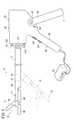
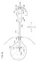
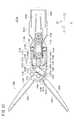
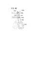
図1は、一実施形態に係る医療用マニピュレータ10の全体構成を示す側面図である。本実施形態では、主に腹腔鏡下手術において使用される鉗子である医療用マニピュレータ10を例示して説明するが、本発明は鉗子以外、例えば、挟や電気メス等の各種外科用器具にも適用可能である。また、以下の説明では、図1に示された医療用マニピュレータ10の右側を基端、左側を先端と称し、他の図面においても同様とする。 FIG. 1 is a side view showing an overall configuration of a
医療用マニピュレータ10は、患部への外科的処置を行うエンドエフェクタとしてのグリッパ22を先端に設けた先端動作部14、及び、該先端動作部14の基端側に連結された細径且つ長尺な連結部12を備える作業部(器具本体)15と、連結部12の基端側に連結された操作部16と、連結部12内を挿通して先端動作部14と操作部16との間を接続する長尺な伝達部材18(図2参照)とから構成されている。操作部16には、当該医療用マニピュレータ10に内装される各種アクチュエータ等の駆動制御を行う制御部であるコントローラ20が接続されている。 The
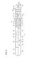
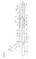
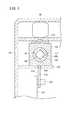
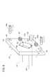
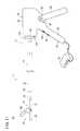
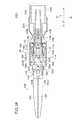
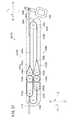
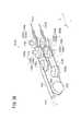
図2は、図1に示す医療用マニピュレータ10の先端動作部14近傍を拡大した部分断面側面図であり、先端動作部14に設けられたグリッパ22を閉じた状態を示しており、図3は、図2に示す状態からグリッパ22を開いた状態での部分断面側面図である。また、図4は、図1に示す医療用マニピュレータ10の操作部16近傍を拡大した部分断面側面図であり、先端動作部14に設けられたグリッパ22を閉じた状態を示しており、図5は、図4に示す状態からグリッパ22を開いた状態での部分断面側面図である。 2 is a partial cross-sectional side view in which the vicinity of the distal
連結部12は、内部に伝達部材18等を収納し得る空間24が形成された中空且つ細径の長尺部材であり、その先端には、先端動作部14と回転可能に連結される接合部(姿勢変更機構、回転機構)26が設けられる(図1及び図2参照)。該連結部12の基端は、操作部16を構成する操作部本体28に連結されている(図1及び図4参照)。 The connecting
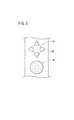
連結部12の横断面形状(軸方向に直交する方向での断面形状)は、例えば、円形、楕円形、多角形等、特に限定されない。本実施形態では、図6に示すように円形とされ、その外径は、トラカール管(図示せず)に挿入可能な程度、例えば、5〜10mm程度とされる。 The cross-sectional shape (cross-sectional shape in the direction orthogonal to the axial direction) of the connecting
本実施形態の場合、連結部12は、図1に示すように直線状をなしているが、これに限らず、所望の形状に予め湾曲又は屈曲されたものであってもよい。なお、連結部12は、所望の形状に湾曲(屈曲)変形可能な少なくとも1つの湾曲部(姿勢変更機構、屈曲機構)30を有しており(図1参照)、これによりグリッパ22による生体組織上の外科的処置の可能な領域を拡大し、一層適正な姿勢で外科的処置を行うことを可能としている。 In the case of the present embodiment, the connecting
このような連結部12内を挿通する伝達部材18は、線状体32と、該線状体32の基端側に連結された第1の連結部材34と、線状体32の先端側に連結された棒状の第2の連結部材36とから構成されている。なお、線状体32は、連結部12と操作部16とが着脱可能に連結された着脱部35近傍に接続部37(図4及び図12参照)を有し、これにより、先端側部位32aと基端側部位32bとを着脱可能に接続している。この場合、先端側部位32aは先端動作部14内へと延び、基端側部位32bは操作部本体28内へと延びている(図2及び図4参照)。 The
線状体32としては、その全部又は一部、少なくとも湾曲部30に対応する部分に可撓性を有するもの(湾曲可能なもの)であることが好ましく、例えば、ステンレス鋼、タングステン、超弾性合金等よりなる金属線やピアノ線、ロープやチェーン等、さらには、ポリアミド(全芳香族系ポリアミド)、ポリエステル、超高分子量ポリエチレン、カーボン繊維等の比較的高張力に耐え得る高分子材料よりなる繊維(以下、高張力繊維という)を素線とするもの、あるいは、これらの素線のうちの任意のものの集合体またはその他の複合体を用いることができる。当然、湾曲部30に対応する部分以外の直線部は、可撓性ではない剛体で構成されていてもよい。この場合、素線の集合体による線状体32としては、例えば、1本以上の前記素線(特に金属線)の外周に、1本以上の同種または異種の素線を所定方向に巻きつけ(例えばコイル状に)、さらにその外周に1本以上の同種または異種の素線を前記と逆方向に巻きつけたものが好適に使用される。このような線状体によれば、操作部16における牽引操作に対する追従性に優れるとともに、線状体32を回転したときに、ねじれや曲げによる長さの変化(歪み)が抑制されるという利点がある。線状体32の外径は、特に限定されないが、本実施形態の場合、1.0〜2.5mm程度、特に1.0〜1.5mm程度とされる。 It is preferable that the
図2及び図6に示すように、第2の連結部材36は、その横断面形状が四角形をなす一方、接合部26を構成する凸部38の中心部には、第2の連結部材36が摺動自在に挿通する通路40が形成されている。すなわち、通路40の横断面形状は、前記の第2の連結部材36と略同形状とされている。この場合、第2の連結部材36の先端は、先端動作部14の内部へと延び、後述するスライダ44の基端と連結又は一体化されている。 As shown in FIGS. 2 and 6, the second connecting
なお、第2の連結部材36の横断面形状は、四角形以外にも、例えば、三角形、六角形、半円形、一文字状、十文字状、L字状等の非円形のように、通路40に対し回転を阻止し得る任意の形状とすることができる。また、第2の連結部材36の構成材料としては、例えば、アルミニウム、真鍮、ステンレス鋼、タングステン、炭素鋼、超弾性合金等の金属材料、ポリカーボネート、ポリエチレン、ポリプロピレン、硬質ポリ塩化ビニル、ポリエステル等の比較的硬質な樹脂又は前記高張力繊維等を挙げることができる。 Note that the cross-sectional shape of the second connecting
図2及び図3に示すように、先端動作部14には、患部の処置を行うエンドエフェクタとしてのグリッパ22と、前記スライダ44を一方側(先端側)に付勢するコイルばね46とが設けられている。グリッパ22は、生体組織を挟持し得る鉗子機構を構成するもので、一方が駆動して開閉する一対の開閉部材、すなわち、固定挟持片48と、該固定挟持片48に対し回動する可動挟持片50とを有する。可動挟持片50は、その基端部において、ピン52により先端部本体54に対し回動可能に取り付けられている。なお、本実施形態の場合、グリッパ22は、いわゆる片開き式であるが、両開き式の構成としてもよい。 As shown in FIGS. 2 and 3, the distal
先端部本体54の下部(図2中下方)には、切欠き56が形成されており、この切欠き56内には、先端動作部14の長手方向に摺動可能なスライダ44が設置されている。スライダ44の先端部には、ピン58が突設されており、このピン58は、可動挟持片50の基端下部に形成された長孔60内に挿入されている。 A
従って、このような先端動作部14では、後述するハンドル部62のハンドル操作により伝達部材18が基端側へ牽引され、スライダ44が切欠き56内の基端側に位置する場合には、固定挟持片48及び可動挟持片50が閉じ位置となる(図2参照)。一方、ハンドル部62の握持力が緩和又は除去されると、伝達部材18が先端側へ移動して、スライダ44が切欠き56内の先端側へ移動する。そうすると、ピン58が長孔60の内周面を押圧し、これにより、可動挟持片50がピン52を中心に回動して可動挟持片50が開かれる(図3参照)。なお、長孔60を設けず、スライダ44の移動に伴ってスライダ44が歪み、ピン58の図2中上下方向の動きを吸収するような構成とすることもできる。 Therefore, in such a distal
この場合、先端部本体54に形成された凹部64及びスライダ44に形成された凹部66内には、コイルばね46が圧縮状態で収納されている。コイルばね46は、その弾性力によりスライダ44を先端方向へ付勢、すなわち、可動挟持片50を開く方向に付勢する付勢手段である。このように、本実施形態に係る医療用マニピュレータ10では、付勢手段であるコイルばね46を先端動作部14に内蔵しているため、例えば、ハンドル部62に可動ハンドル68を開く方向に付勢する板バネ等を設ける必要がなく、操作部16の構成を簡素化し、操作性を向上させることができる。 In this case, the
図2及び図3に示すように、接合部26は、連結部12の空間24に連通し、連結部12の先端面に開口する横断面形状が円形の凹部70と、先端部本体54の基端から突出し、前記凹部70に挿入される横断面形状が円形の凸部38とから構成されている。 As shown in FIGS. 2 and 3, the
凸部38の中心部には、第2の連結部材36の横断面形状と略同形状の通路40が軸方向に形成され、該通路40に第2の連結部材36が挿通されることにより、伝達部材18の回転力が凸部38及び先端部本体54に伝達される。 A
凹部70の内周面には、軸方向に所定間隔を隔てて、2つのリング状の溝74が形成されている。一方、凸部38の外周面には、前記各溝74に対応する位置に2つのリング状の隆起部75が周方向に沿って形成されている。これら隆起部75は、それぞれ、対応する溝74内に挿入されている。なお、隆起部75は、連続したリング状のものに限らず、周方向に沿って間欠的に設けられていてもよい。 Two ring-shaped
以上のような構成の接合部26により、先端動作部14は、連結部12に対して回転(ロール)可能であるが、軸方向へはほとんど移動不能とされるため、先端動作部14の離脱やガタツキを確実に防止することができる。なお、接合部26には、先端動作部14の回転抵抗を減少する回転抵抗減少手段(図示せず)を設けることもできる。その具体例としては、凹部70と凸部38と間に、潤滑油等の潤滑剤を介在させ、又は、例えばポリテトラフルオロエチレン、シリコーン、ポリエチレン、ポリアセタールのような低摩擦材料の層を形成することが挙げられる。これにより、先端動作部14の回転をより円滑に行うことができる。 With the
図1、図4及び図5に示すように、連結部12の基端側には、グリッパ22の開閉(回動)、湾曲部30での先端動作部14の屈曲動作及び連結部12に対する先端動作部14の回転動作を遠隔的に操作する操作部16が設けられている。 As shown in FIGS. 1, 4, and 5, on the proximal end side of the connecting
操作部16は、操作部本体28に対し固定され又は一体に設けられた固定ハンドル80と、該固定ハンドル80に対し開閉(回動)する可動ハンドル68とから構成されるハンドル部62を有する。可動ハンドル68は、その上端部において、軸部材82により操作部本体28に対し回動可能に取り付けられている。 The
操作部本体28の下部外面には、可動ハンドル68を係止してその回動範囲を規制するストッパ84が突出形成されている。これにより、ハンドル部62に過度の握持力が加わることによる伝達部材18の断線等を防止することができる。なお、図13に示すように、固定ハンドル80と可動ハンドル68の位置は、反対であってもよく、この場合には、後述する回転操作入力部86や屈曲操作入力部128の配置も合わせて、例えば、操作部本体28の基端上部等に変更するとその操作性を一層向上させることができる。 A
また、操作部16は、操作部本体28の基端側に、固定ハンドル80に設けられた円盤状の回転操作入力部86(図8参照)の操作によって駆動される回転操作機構88を有する。 The
回転操作機構88は、例えば、モータからなる回転用駆動源(アクチュエータ)90と、該回転用駆動源90の回転軸に連結された小径の駆動歯車92と、該駆動歯車92に噛合う大径の従動歯車94と、該従動歯車94を操作部本体28の基端に回転可能に支持する軸受96とから構成されている。回転用駆動源90は、回転操作入力部86の操作に基づくコントローラ20の制御下に駆動制御される。前記従動歯車94の回転軸98は、基端側の円柱部98aと、それより先端側の角柱部98bとから構成され、円柱部98aにおいて軸受96により支持されている。 The
操作部本体28の内部には、可動ハンドル68の回動を伝達部材18の長手方向の移動に変換すると共に、従動歯車94の回転により生じた回転力を伝達部材18に伝達する変換手段100が設置されている。変換手段100は、第1の連結部材34を回転可能に支持する支持部材102と、従動歯車94の回転力を第1の連結部材34に伝達する回転力伝達機構104とを有する。 Inside the operation unit
この場合、線状体32の基端側部位32bは、ピン106により第1の連結部材34の先端部に固定されている。該第1の連結部材34は、その中心部に、従動歯車94の回転軸98の角柱部98bが挿入される横断面形状が四角形の通路108が形成された円筒状の部材であり(図7参照)、その基端には、支持部材102の基端面に係合するフランジ110が形成されている。 In this case, the proximal
支持部材102は、第1の連結部材34が挿入される横断面形状が円形の貫通孔112を有している。支持部材102の下部には、長孔114が形成された舌片116が突出形成されている。このような支持部材102は、操作部本体28の内側に設けられたガイド部材118、120により、伝達部材18の長手方向に摺動可能に支持されている。舌片116は、下方のガイド部材120に形成されたスリット122を貫通して下方へ突出している。 The
一方、可動ハンドル68の上部には、操作部本体28の内部に挿入された突出片124が設けられ、該突出片124の上端部に立設されたピン126が前記舌片116の長孔114に挿入されている(図4及び図7参照)。 On the other hand, a protruding
回転力伝達機構104は、従動歯車94の回転軸98を構成する角柱部98bと、該角柱部98bが挿入される通路108とで構成されている。角柱部98bは、通路108に対し、軸方向には相対的に移動可能であるが、通路108内への挿入深さにかかわらず、通路108に対し、回転することはできない。従って、従動歯車94の回転力は、角柱部98bおよび通路108を介して第1の連結部材34に伝達され、伝達部材18全体が回転する。 The rotational
なお、角柱部98bの横断面形状は、四角形以外にも、例えば、三角形、六角形、半円形、一文字状、十文字状、L字状等の非円形のように、通路108に対し回転を阻止し得る任意の形状とすることができる。また、回転力伝達機構104としては、回転用駆動源90からの回転力を伝達部材18に機械的に伝達する機構が用いられ、例えば、ワイヤ、チェーン、タイミングベルト、リンク、ロッド、ギア等を介して駆動するものであってもよく、動力伝達方向に非弾性な個体の機械部品を介して駆動する方式とすることが好ましい。ワイヤやチェーン等は、張力により不可避的な多少の伸びが発生する場合があるが、これらは非弾性な個体の機械部品とする。そこで、これらの駆動機構を用いて、回転操作機構88と先端動作部14との回転方向を逆としたり、変速したりすることもできる。 In addition to the quadrangular shape, the
さらに、操作部16は、操作部本体28の先端側に、固定ハンドル80に設けられた上下(前後)左右を指す4個の三角形のボタンからなる屈曲操作入力部128(図8参照)の操作によって駆動され、湾曲部30を屈曲動作させる屈曲操作機構130を有する。 Further, the
図4、図5及び図9に示すように、屈曲操作機構130は、操作部本体28の先端面から突出する2本のコイルばね132、134と、該コイルばね132及び134間に並設された揺動支軸(ベアリング球)136と、前記コイルばね132、134の先端側に連結され、操作部本体28の先端面から所定距離離間して対向配置された傾斜板(揺動板)138とを備える。傾斜板138の中央部には、操作部本体28の先端側に突出して連結部12に連結される略円筒形状の突出部139が挿通する孔部138aが形成されている。 As shown in FIGS. 4, 5, and 9, the bending
さらに、屈曲操作機構130は、操作部本体28内に配置され、例えば、ギヤードモータからなる2つの屈曲用駆動源(アクチュエータ)140、142を有する。屈曲用駆動源140、142の駆動軸に連結された進退ねじ部140a、142aは、操作部本体28の先端面に形成されたねじ孔部144、146を螺回して通過した状態で、その先端面が、傾斜板138に対角に設けられた2つの受け部148、150に当接している。 Furthermore, the bending
従って、このような屈曲操作機構130では、コントローラ20の制御下に屈曲用駆動源140、142が駆動制御され、進退ねじ部140a、142aが適宜進退駆動されることにより、傾斜板138は、揺動支軸136の球状の先端面を支点として、コイルばね132、134による弾性支持作用によって所望の方向(図9中の矢印A、B方向)に所望の角度で傾斜されることになる。この際、一方の受け部150が横長に形成されていることから、傾斜板138が傾斜した状態でも、他方の進退ねじ部140aを他方の受け部148に当てた状態で、当該受け部150に確実に一方の進退ねじ部142aを当てながら傾斜板138を円滑に揺動操作することができる。なお、このような屈曲操作機構130における傾斜板138の傾斜動作としては、一般的な光学ミラーの煽り構造をなす機構を利用することができる。 Therefore, in such a
また、傾斜板138の孔部138aには、図中の上下左右方向に4本のスリット152が形成されている。各スリット152内にはそれぞれ孔部138aの内周側からワイヤ(線材)154が挿入されると共に、各ワイヤ154の基端側に設けられた拡径部154aが傾斜板138の基端側の面に係合し、各ワイヤ154は連結部12に軸方向に延びた4本の貫通孔156内を挿通し、湾曲部30まで達している。 Further, four
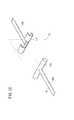
図10は、連結部12の湾曲部30の構成例を部分的に示す分解斜視図である。湾曲部30は、相互に回動し得る複数の節輪環158を接合したものである。なお、図10では、3個の節輪環158を例示して湾曲部30を説明するが、節輪環158の設置数はこれに限定されず、例えば、4〜30個程度であってもよい。 FIG. 10 is an exploded perspective view partially showing a configuration example of the bending
各節輪環158の一方の面には、節輪環158の中心を介して対向する一対のV字状の溝160が形成され、他方の面には、節輪環158の中心を介して対向する一対の半円柱状の突部162が前記溝160と90°ずれた位置に形成されている。この場合、隣接する節輪環158同士は、それらの溝160同士が互いに90°ずれた姿勢で配置され、一方の節輪環158の両突部162が他方の節輪環158の対応する両溝160内に挿入されるようにして各節輪環158が接合される。 A pair of V-shaped
また、各節輪環158において、両溝160及び両突部162が形成された位置には、それぞれ貫通孔164が形成されており、各節輪環158の対応する貫通孔164には、前記傾斜板138に基端側の拡径部154aが係合された4本のワイヤ154がそれぞれ挿通すると共に、当該ワイヤ154の先端が湾曲部30の先端側に配列された節輪環158に連結されている(図2及び図3参照)。これにより、各節輪環158が集合され略一体的に構成される。 Further, in each
このような湾曲部30では、突部162が溝160に挿入された状態では、隣接する節輪環158の間には隙間が形成されるため、突部162が溝160内で回動することができ、これにより、隣接する節輪環158同士が回動することができる。この場合、隣接する1組の節輪環158同士の回動角度は、僅かであるが、その角度が複数組の節輪環158について累積すると、湾曲部全体として所望の湾曲(例えば60〜120°程度)を得ることができ、先端動作部14(グリッパ22)を連結部12の長尺軸と非平行な状態に曲げることができる。 In such a
そこで、屈曲操作入力部128が操作されることにより、コントローラ20の制御下に、屈曲操作機構130が適宜駆動制御され、傾斜板138が所望の角度に傾斜されると各ワイヤ154がそれぞれ所定距離だけ進退移動され、これにより、湾曲部30を連結部12の横断面上で上下(前後)左右に所望の角度で屈曲させることができる。すなわち、湾曲部30は、ワイヤ154の傾斜板138による牽引により能動的に屈曲又は湾曲する。この場合、湾曲方向やその数(自由度)は、特に限定されるものではなく、また、図示されていないが、各節輪環158の外周を、例えば、弾性または可撓性を有する材料で構成された層で被覆することも可能である。 Therefore, when the bending
なお、湾曲部30の構成は、図示のものに限定されず、例えば、蛇腹管や可撓性チューブを有する構成であってもよい。また、連結部12を先端部側の硬管と基端部側の硬管とで構成し、両硬管同士を1本または複数本の軸により回動可能に接続することで屈曲させる構成としてもよい。さらには、ピボット軸を有する屈曲機構とすることもできる。 In addition, the structure of the bending
図11に示すように、本実施形態に係る医療用マニピュレータ10では、操作部16と連結部12とが、着脱部35において着脱可能(分離可能)とされている。すなわち、連結部12と操作部16とを着脱可能に連結する着脱部35では、操作部16の先端側に突出した突出部139が、連結部12の基端側の孔部166内に挿入された状態で、連結部12を外周側から内周側に向かって止めねじ168が締結され、これにより、連結部12と操作部16とが固定される(図4及び図5参照)。 As shown in FIG. 11, in the
従って、連結部12と操作部16とを分離する際には、傾斜板138のスリット152から各ワイヤ154を離脱すると共に、止めねじ168を緩めて操作部16の突出部139を連結部12の孔部166から引き抜くだけでよい(図11参照)。この際、線状体32については、先端側部位32aと基端側部位32bとが接続部37において、例えば、先端側部位32aの基端側にT字に形成されたバー170を、基端側部位32bの先端側にT字に形成されたフック172から離脱させるだけで容易に分離することができる(図12参照)。これにより、例えば、1つの操作部に対して、各種のエンドエフェクタを有する先端動作部を備える作業部15に容易に変更することができ、医療用マニピュレータ10の汎用性を低コストで向上させることができる。また、作業部15を操作部16から容易に分離できることから、作業部15(先端動作部14)の交換や洗浄、さらには高温滅菌等のメンテナンス性も向上させることができる。 Therefore, when separating the
なお、以上のように構成される医療用マニピュレータ10では、グリッパ22の操作(開閉又は回動)と先端動作部14の回転操作とを単一の伝達部材18で兼用しているため、連結部12内での伝達部材18の設置スペースが小さくてよい。このため、連結部12をより細くすることができるとともに、先端動作部14や操作部16の構造も簡素化することができる。従って、本実施形態に係る医療用マニピュレータ10は、腹腔鏡下手術、脳外科手術、胸腔鏡下手術、泌尿器科手術等に好適に使用することができる。 In the
次に、医療用マニピュレータ10の作用について説明する。 Next, the operation of the
先ず、初期状態(非操作状態)では、コイルばね46の付勢力によりグリッパ22が開かれ、可動ハンドル68が開いた状態とされている(図1、図3及び図5に示す状態)。そこで、ハンドル部62を手で握り、可動ハンドル68を図1中の矢印で示す方向に回動させると、突出片124が軸部材82を中心に図中時計回りに回動し、ピン126が長孔114の基端側内周面を押圧し、舌片116及び支持部材102がガイド部材118、120に沿って基端側へ移動する(図4に示す状態)。支持部材102の基端には、フランジ110が係合しているため、支持部材102の移動に伴って第1の連結部材34も同方向に移動し、これにより、伝達部材18が基端側へ牽引される。この場合、支持部材102の基端方向への移動に伴い、角柱部98bの先端は、通路108内の比較的深部まで挿入される。 First, in the initial state (non-operating state), the
伝達部材18が基端側へ牽引されると、これに伴い、スライダ44がコイルばね46の付勢力に抗して切欠き56内で基端側に移動する。このため、ピン58が長孔60の基端側内周面を押圧し、可動挟持片50がピン52を中心に図2中反時計回りに回動して、可動挟持片50が閉じられる(図2に示す状態)。 When the
一方、ハンドル部62を握っていた手を離すか又は握持力をゆるめると、コイルばね46の付勢力によりスライダ44が切欠き56内で先端側に移動する。このため、ピン58が長孔60の先端側内周面を押圧し、可動挟持片50がピン52を中心に図3中時計回りに回動して、可動挟持片50が開かれる(図3に示す状態)。 On the other hand, when the hand holding the
このようなスライダ44の先端方向への移動に伴い、伝達部材18も同方向に移動し、伝達部材18の基端部においては、フランジ110が支持部材102を押圧し、支持部材102および舌片116がガイド部材118、120に沿って先端側へ移動する。これにより、長孔114の基端側内周面がピン126を押圧し、突出片124および可動ハンドル68が軸部材82を中心に図5中時計回りに回動し、可動ハンドル68は、元の開いた状態(図5に示す状態)に復帰することになる。この場合、支持部材102の先端方向への移動に伴い、角柱部98bの先端は、通路108内の長手方向中央付近まで移動する。 As the
この場合、可動挟持片50の開閉は、可動ハンドル68の開閉に機械的(直接的)に連動していることから、人手により可動ハンドル68をある程度引いたときに、グリッパ22が対象物(手術器具や生体組織等)を把持すると、グリッパ22及びスライダ44はそれ以上動かなくなる。これにより、伝達部材18もそれ以上動かなくなり、操作者はグリッパ22が対象物を把持したことを指先で知覚することができる。 In this case, since the opening / closing of the
また、前記の対象物が手術器具等の硬いものであるときには、可動ハンドル68は閉じ方向には全く動かなくなり、硬いものを把持したことを知覚できると共に、対象物を強い力で確実に把持することができる。電磁力を介さずに人手による力を機械的且つ直接的にグリッパ22に伝達できるからである。仮に人手による力と同等の把持力をモータによって発生させようとすると、相当に大きく重いモータが必要であり、操作部本体28内に納めることが困難であるとともに、医療用マニピュレータ10が重量増となる。 Further, when the object is a hard object such as a surgical instrument, the
対象物が生体組織等の柔らかいものであるときには、可動ハンドル68は対象物の弾性に応じて閉じ方向にやや変位可能であり、柔らかいものを把持したことを知覚できるとともに、柔らかさの程度が分かり、しかも対象物を把持する力を調整することができる。 When the object is soft such as a living tissue, the
医療用マニピュレータ10では、伝達部材18等が摩耗又は劣化した場合においても、摩擦等が増加して可動ハンドル68に伝達され、これらの状態変化や駆動系の異常状態等を操作者が感知することができ、メンテナンス等の時期をより適切に判断することができる。 In the
以上のように、可動挟持片50の開閉は、可動ハンドル68の開閉に機械的(直接的)に連動しており、固定挟持片48及び可動挟持片50の開度(把持力)は、固定ハンドル80及び可動ハンドル68の開度(握持力)に対応している。このため、操作者は、グリッパ22を所望の開度(把持力)に容易に操作することができる。 As described above, the opening and closing of the
すなわち、可動ハンドル68の人手による操作は機械的に伝達されてグリッパ22の開閉が行われる。可動ハンドル68とグリッパ22との間で、人手による操作を機械的に伝達する手段である伝達部材18やスライダ44等は操作伝達部を形成している。 That is, the manual operation of the
ここで機械的とは、上記のように、ワイヤ、チェーン、タイミングベルト、リンク、ロッド、ギア等を介して駆動する方式であり、主に、動力伝達方向に非弾性な個体の機械部品を介して駆動する方式であり、ワイヤやチェーン等は、張力により不可避的な多少の伸びが発生する場合があるが、これらは非弾性な個体の機械部品とする。例えば、伝達部材18は、少なくとも湾曲部30に対応する一部に可撓性を有するが、コイルばね46によって適度に張られており、しかもグリッパ22を閉じる動作に関しては可動ハンドル68によって操作部16側に引かれ、ほとんど弾性変形することがなく、又は動作に支障のない範囲での不可避的弾性変形であり、機械的接続手段(機械的伝達手段)となっている。 Here, mechanical is a method of driving through wires, chains, timing belts, links, rods, gears, etc. as described above, mainly through individual mechanical parts that are inelastic in the power transmission direction. In some cases, the wire, the chain, and the like are inevitably somewhat elongated due to the tension, but these are inelastic individual mechanical parts. For example, the
一方、可動挟持片50の開閉(開度)にかかわらず、回転操作入力部86を操作して回転用駆動源90を駆動して従動歯車94を回転させると、その回転力は、回転軸98の角柱部98b、通路108、第1の連結部材34、線状体32、第2の連結部材36、通路40、凸部38および先端部本体54に順次伝達され、これにより、先端動作部14が回転する。すなわち、回転操作機構88及び接合部26等が、先端動作部14を軸周りに回転させる回転機構として機能する。この場合、従動歯車94の回転方向は、先端動作部14の回転方向に一致している。 On the other hand, regardless of opening / closing (opening degree) of the
なお、グリッパ22の開閉動作および先端動作部14の回転動作は、連結部12の直線状態、屈曲又は湾曲状態のいずれにおいても可能である。特に、本実施形態に係る医療用マニピュレータ10では、連結部12が屈曲又は湾曲した状態(図1中の二点鎖線で示す状態)であっても、湾曲部30は回転せず、先端動作部14のみが回転するため、回転に伴って先端動作部14が湾曲部30より基端側の軸を中心に揺動することがない。従って、グリッパ22の外科的処置を施す目的部位への接近状態を維持したままグリッパ22の姿勢(生体組織を把持する方向)を変えることができる。 Note that the opening / closing operation of the
この場合、屈曲操作機構130についても、可動挟持片50の開閉(開度)にかかわらず、屈曲操作入力部128を操作して屈曲用駆動源140、142を駆動するだけで、傾斜板138を所望の角度に傾斜させ、これにより、連結部12を湾曲部30において所望の角度に容易に屈曲させることができる。すなわち、湾曲部30及び屈曲操作機構130が、グリッパ22を連結部12の軸方向と交差する方向に屈曲させる屈曲機構として機能して、グリッパ22の姿勢を容易に且つ迅速に変更することができる。 In this case, with respect to the
以上のように、本実施形態に係る医療用マニピュレータ10では、屈曲操作機構130及び湾曲部30による連結部12の屈曲動作と、回転操作機構88による先端動作部14の回転動作とが、それぞれ操作部16に設けられた屈曲操作入力部128と回転操作入力部86とを指先で操作するだけで、コントローラ20の制御下に、アクチュエータである屈曲用駆動源140、142及び回転用駆動源90を介して容易に且つ迅速に行うことができ、高い操作性を得ることができる。すなわち、医療用マニピュレータ10では、連結部12の一部(湾曲部30)を屈曲させる屈曲機構と、先端動作部14を回転させる回転機構とが、先端動作部14の姿勢を変える姿勢変更機構として機能し、これらはアクチュエータを介して動作する。一方、先端動作部14を構成するグリッパ22の開閉(回動)は、屈曲操作機構130等の動作と独立して、固定ハンドル80及び可動ハンドル68によって操作者が手動で機械的(直接的)に操作して、グリッパ22を所望の把持力で操作することができるため、患部への処置をより適切に行うことができると共に、把持したものの硬さ等を感じ取ることができる。すなわち、エンドエフェクタ(グリッパ22)については、人手による操作を機械的に直接伝達して動作させることが理想である一方、他の姿勢軸である屈曲操作機構130及び湾曲部30や回転操作機構88の動作、つまり、姿勢変更機構の動作については、アクチュエータ(屈曲用駆動源140、142及び回転用駆動源90)を用いて操作を簡便化することが最良である。すなわち、本案を用いれば、例えば指先一本の簡便なボタン操作等で容易に先端動作部14の姿勢を変更可能に構成することができるため、前記したグリッパ22の開閉や医療用マニピュレータ10全体を操作者が腕を使って動かす作業を妨げることなく、より直感的に外科処置を行うことができる。 As described above, in the
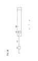
図14は、図1に示す医療用マニピュレータ10の先端部の別の構成例を示す部分断面側面図である。 FIG. 14 is a partial cross-sectional side view showing another configuration example of the distal end portion of the
図14に示す先端動作部180は、可動挟持片50を開く方向に付勢する付勢手段が、先端動作部14の近傍に設けられた構成とされている。すなわち、連結部12の接合部26の基端側に隣接する位置には、空間24が拡径した拡径部182が形成されており、該拡径部182内には、前記と同様のコイルばね46が収納されている。拡径部182内において、第2の連結部材36は、コイルばね46の内側に挿通されており、連結部材36のコイルばね46より先端側には、円盤状の鍔部184が固着または一体形成されている。圧縮状態のコイルばね46は、その基端が拡径部182の基端面に、その先端が鍔部184に当接しており、第2の連結部材36を先端方向へ付勢する。 The
なお、例えば、前記の付勢手段は、コイルばね46に限らず、例えば、トーションバネ、板バネ等の他の形態のバネや、ゴムのような弾性材料、あるいは永久磁石、電磁石を用いることができる。また、このような付勢手段は、操作部16に設けられていてもよい。 For example, the biasing means is not limited to the
手術において、組織の剥離作業などにおいては、グリッパ22を開く方向(つまり剥離方向)に大きな剥離力が必要となることがある。このようなときにコイルばね46を引っ張りばねにした構成でスライダ44を介して可動ハンドル68の押し出し操作をグリッパ22に直接的に伝達すると、大きな剥離力が得られて好適である。この場合、医療用マニピュレータ10では、グリッパ22の開方向の力が可動ハンドル68に伝達される。つまり、グリッパ22を開く場合で開き方向に生体組織や手術器具等に当接した場合には、可動ハンドル68が開き方向には動かなくなる。これにより、操作者はグリッパ22が何かに当接したことを感知する。 In surgery, tissue peeling work or the like may require a large peeling force in the direction of opening the gripper 22 (that is, the peeling direction). In such a case, if the pushing operation of the
また、回転操作機構88、屈曲操作機構130、接合部26、変換手段100、操作部16、着脱部35、接続部37等の構成も、それぞれ、図示のものに限定されない。また、本実施形態において、外科動作手段は、双方が回動する一対の開閉部材で構成されたものであってもよい。また、回動に限らず、例えば、平行移動して開閉する構成のものでもよい。さらには、例えばおじぎ鉗子、電気メス、超音波メスのように、一つの部材が回動する構成のものであってもよい。 In addition, the configurations of the
さらに、回転操作機構88及び屈曲操作機構130を駆動するアクチュエータである回転用駆動源90及び屈曲用駆動源140、142についても、電動モータ以外にも、例えば、気体や液体等の流体を用いる流体圧アクチュエータとしてもよい。 Further, for the rotation drive
また、回転操作入力部86及び屈曲操作入力部128は、操作部16に設ける以外にも、例えば、フットスイッチとして構成し、操作者の足下に載置するように構成して操作者が手技を一層円滑に行うことができるように構成することもできる。 In addition to the rotation
さらにまた、操作部16における可動ハンドル68、回転操作入力部86及び屈曲操作入力部128の位置、形態や操作方法などは、本構成に限定されない。例えば、回転操作入力部86の代わりに、操作ローラやボタン、ジョイスティック等を設けてもよく、操作しやすい位置や方法を適宜選択して設計すればよい。 Furthermore, the positions, forms, operation methods, and the like of the
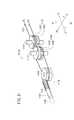
次に、別の一実施形態に係る医療用マニピュレータ1010について、図15〜図57を参照して説明する。 Next, a
図15に示すように、本実施形態に係る医療用マニピュレータ1010は、医療用マニピュレータシステムの一部であり、コントローラ1045に接続されている。 As shown in FIG. 15, a
コントローラ1045は、医療用マニピュレータ1010の電気的な制御をする部分であり、グリップハンドル1026の下端部から延在するケーブル1062に対してコネクタを介して接続されている。コントローラ1045は、医療用マニピュレータ1010を独立的に複数台同時に制御することができる。もちろん、1台の医療用マニピュレータ1010を制御するコントローラを用いてもよい。 The
医療用マニピュレータ1010は、先端動作部1012に生体の一部又は湾曲針等を把持して所定の外科的処置を行うためのものであり、通常、把持鉗子やニードルドライバ(持針器)等とも呼ばれる。 The
図15及び図16に示すように、医療用マニピュレータ1010は、人手によって把持及び操作される操作部1014と、該操作部1014に固定された作業部1016とを有する。操作部1014と作業部1016とは一体構成であるが、条件に応じて分離可能な構成にしてもよい。 As shown in FIGS. 15 and 16, the
以下の説明では、図15及び図16における幅方向をX方向、高さ方向をY方向及び、連結シャフト1048の延在方向をZ方向と規定する。また、先端側から見て右方をX1方向、左方をX2方向、上方向をY1方向、下方向をY2方向、前方をZ1方向、後方をZ2方向と規定する。さらに、特に断りのない限り、これらの方向の記載は医療用マニピュレータ1010が中立姿勢である場合を基準として表すものとする。これらの方向は説明の便宜上のものであり、医療用マニピュレータ1010は任意の向きで(例えば、上下を反転させて)使用可能であることはもちろんである。 In the following description, the width direction in FIGS. 15 and 16 is defined as the X direction, the height direction is defined as the Y direction, and the extending direction of the connecting
作業部1016は、作業を行う先端動作部1012と、該先端動作部1012と操作部1014とを連接する長尺で中空の連結シャフト(連結部)1048とを有する。先端動作部1012及び連結シャフト1048は細径に構成されており、患者の腹部等に設けられた円筒形状のトラカール1020から体腔1022内に挿入可能であり、複合入力部1034の操作により体腔1022内において患部切除、把持、縫合及び結紮等の様々な手技を行うことができる。 The working
操作部1014は、人手によって把持されるグリップハンドル1026と、該グリップハンドル1026の上部から延在するブリッジ1028と、該ブリッジ1028の先端に接続されたアクチュエータブロック1030とトリガレバー(入力部)1032を有する。 The
図15に示すように、操作部1014のグリップハンドル1026は、ブリッジ1028の端部からY2方向に向かって延在しており、人手によって把持されるのに適した長さであり、複合入力部1034を有する。 As shown in FIG. 15, the
グリップハンドル1026の下端には、コントローラ1045に接続されるケーブル1062が設けられている。グリップハンドル1026とケーブル1062とは一体的に接続されている。グリップハンドル1026とケーブル1062とはコネクタにより接続されていてもよい。 A
複合入力部1034は、先端動作部1012に対してロール方向(軸回転方向)及びヨー方向(左右方向)の回転指令を与える複合的な入力手段であり、例えば横方向に動作する第1入力手段1034aによってヨー方向指示を行い、軸回転に動作する第2入力手段1034bによってロール方向指示を行うことができる。トリガレバー1032は、先端動作部1012のエンドエフェクタ1104(図15参照)の開閉指令を与える入力手段である。エンドエフェクタ1104としては種々の形式があるが、医療用マニピュレータ1010では開閉可能なグリッパを設けている。 The
複合入力部1034には操作量を検出する入力センサが設けられており、検出した動作信号(例えばアナログ信号)をコントローラ1045に供給する。 The
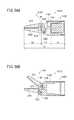
トリガレバー1032は、ブリッジ1028のやや下方に設けられたレバーであり、人差し指による操作が容易な位置に設けられている。トリガレバー1032は、アクチュエータブロック1030に対して第1リンク1064及び第2リンク1066によって接続されており、グリップハンドル1026に対して進退するように構成されている。第1リンク1064はブリッジ1028の一部に対して軸支されて揺動可能であり、Y2方向端にトリガレバー1032が設けられている。第2リンク1066は、アクチュエータブロック1030からZ2方向に突出し、第1リンク1064の長孔1064aに係合し、トリガレバー1032の操作によって長孔1064aの長尺方向に進退可能である。 The
第2リンク1066は、ワイヤ(駆動部材)1056の端部に接続されており、トリガレバー1032を引き寄せる操作をすると、ワイヤ1056も一体的に引き寄せられる。第2リンク1066に接続される駆動部材(伝達部材)としてワイヤ1056を用いることで、部品点数の削減が可能となるとともに、軽量な構成が可能となる。 The
第2リンク1066に接続される駆動部材として、ワイヤ1056に代えて例えば剛性のある直動ロッド(又はリンク)を用いてもよい。一般にワイヤよりロッドのほうが剛性が高いため、直動動作のみの部分は、ロッドを用いることにより大きな把持力を得られる。該ロッドと第2リンク1066とは一体化されていてもよい。 As the drive member connected to the
第2リンク1066とワイヤ1056との間にリンクや歯車等を設け、操作者の操作力又はストロークを加減する構成にしてもよい。 A link, a gear, or the like may be provided between the
アクチュエータブロック1030には先端動作部1012が有する3自由度のうち2自由度の機構に対応してモータ(姿勢軸アクチュエータ)1040及び1041が連結シャフト1048の延在方向に沿って並列して設けられている。モータ1040及び1041は、先端動作部1012のロール方向及びヨー方向の動作、すなわち、先端動作部1012の姿勢を変える姿勢変更機構の動作に対応する。モータ1040、1041は小型、細径であって、アクチュエータブロック1030はコンパクトな扁平形状に構成されている。モータ1040、1041は、操作部1014の操作に基づき、コントローラ1045の作用下に回転をする。モータ1040、1041には、回転角度を検出することのできる角度センサが設けられており、検出した角度信号はコントローラ1045に供給される。角度センサとしては、例えばロータリエンコーダが用いられる。なお、このようなアクチュエータとしては、電動モータ以外にも、例えば、気体や液体等の流体を用いる流体圧アクチュエータとしてもよい。 The
アクチュエータブロック1030には、モータ1040、1041の駆動軸に接続されているプーリ1050a及び1050bが設けられている。 The
プーリ1050a、プーリ1050bには、ワイヤ1052、ワイヤ1054が巻き掛けられており、連結シャフト1048の中空部分1048a(図20参照)を通って先端動作部1012まで延在している。ワイヤ1052、ワイヤ1054はそれぞれ同種、同径のものを用いることができる。 A
操作部1014における複合入力部1034、トリガレバー1032の位置、形態や操作方法などは、本構成に限定されない。例えば、複合入力部1034の代わりに、操作ローラやボタン、ジョイスティックなどを設けてもよく、操作しやすい位置や方法を適宜選択して設計すればよい。 The positions, forms, operation methods, and the like of the
トリガレバー1032の人手による操作は機械的に伝達されてエンドエフェクタ1104の開閉が行われる。トリガレバー1032とエンドエフェクタ1104との間で、人手による操作を機械的に伝達する手段(伝達部材)である第1リンク1064、第2リンク1066、ワイヤ1056及び後述するエンドエフェクタ駆動機構1260等は操作伝達部を形成している。 The manual operation of the
ここで機械的とはワイヤ、チェーン、タイミングベルト、リンク、ロッド、ギア等を介して駆動する方式であり、主に、動力伝達方向に非弾性な個体の機械部品を介して駆動する方式である。ワイヤやチェーン等は、張力により不可避的な多少の伸びが発生する場合があるが、これらは非弾性な個体の機械部品とする。 Here, mechanical is a method of driving via wires, chains, timing belts, links, rods, gears, etc., and is mainly a method of driving via individual mechanical parts that are inelastic in the power transmission direction. . Wires, chains, etc. may have some inevitable elongation due to tension, but these are inelastic solid mechanical parts.
次に、先端動作部1012について、第1の構成例〜第5の構成例1012a〜1012e及び変形例1012fについて説明する。 Next, regarding the distal
図17、図18、図19、図20及び図21に示すように、第1の構成例に係る先端動作部1012aは、ワイヤ受動部1100と、複合機構部1102と、エンドエフェクタ1104とを有し、Y方向の第1回転軸Oyを中心にして、それよりも先の部分がヨー方向に回動する第1自由度と、第2回転軸Orを中心にしてロール方向に回動する第2自由度と、第3回転軸Ogを中心として先端のエンドエフェクタ1104を開閉させる第3自由度とを有する合計3自由度の機構となっている。 As shown in FIGS. 17, 18, 19, 20, and 21, the distal
第1自由度の機構である第1回転軸Oyは、連結シャフト1048の基端側から先端側に延在する軸線Cと非平行に回動可能に設定するとよい。第2自由度の機構である第2回転軸Orは先端動作部1012における先端部(つまりエンドエフェクタ1104)の延在方向の軸線を中心として回動可能な機構とし、先端部をロール回転可能に設定するとよい。 The first rotation axis Oy, which is a mechanism having the first degree of freedom, may be set so as to be rotatable in a non-parallel manner with the axis C extending from the proximal end side to the distal end side of the connecting
第1自由度の機構(つまりヨー方向)は、例えば±90°又はそれ以上の稼動範囲を有する屈曲機構である。第2自由度の機構(つまりロール方向)は、例えば±180°又はそれ以上の稼動範囲を有する回転機構である。第3自由度の機構(つまりエンドエフェクタ1104)は、例えば40°又はそれ以上開くことができる。 The mechanism having the first degree of freedom (that is, the yaw direction) is a bending mechanism having an operating range of ± 90 ° or more, for example. The mechanism of the second degree of freedom (that is, the roll direction) is a rotating mechanism having an operating range of ± 180 ° or more, for example. The third degree of freedom mechanism (ie, end effector 1104) can be opened, for example, 40 ° or more.
エンドエフェクタ1104は、手術において実際の作業を行う部分であり、第1回転軸Oy及び第2回転軸Orは、作業を行い易いようにエンドエフェクタ1104の姿勢を変えるための姿勢変更機構を構成する姿勢軸である。一般に、エンドエフェクタ1104を開閉させる第3自由度に係る機構部はグリッパ(又はグリッパ軸)とも呼ばれ、ヨー方向に回動する第1自由度に係る機構部はヨー軸とも呼ばれ、ロール方向に回動する第2自由度に係る機構部はロール軸とも呼ばれる。 The
ワイヤ受動部1100は、一対の舌片部1058の間に設けられており、ワイヤ1052、ワイヤ1054のそれぞれの往復動作を回転動作に変換して複合機構部1102に伝達する部分である。ワイヤ受動部1100は、軸孔1060a、1060aに挿入される軸1110と、軸孔1060b、1060bに挿入される軸1112とを有する。軸1110及び1112は、軸孔1060a、1060bに対して、例えば圧入若しくは溶接により固定される。軸1112は第1回転軸Oyの軸上に配置される。 The wire
軸1112のY方向両端には、Y方向に対称形状の歯車体1126及び歯車体1130が設けられている。歯車体1126は、筒体1132と、該筒体1132の上部に同心状に設けられた歯車1134とを有する。歯車体1130は、歯車体1126と略同形状であって、該歯車体1126に対してY方向に配置されている。歯車体1130は、筒体1136と、該筒体1136の下部に同心状に設けられた歯車1138とを有する。歯車1134及び歯車1138は、後述するギア体1146のフェイスギア1165の上端部及び下端部に噛合する。 A
筒体1136は筒体1132と略同径、同形状である。筒体1132及び筒体1136には、ワイヤ1052及び1054が所定の固定手段によって一部が固定されて巻き掛けられている。ワイヤ1052及び1054の巻き掛けられる角度は、例えば1.5回転(540°)である。 The
ワイヤ1052及び1054を回転動作させることにより、歯車体1126及び歯車体1130を軸1112に対して回転させることができる。歯車体1126と歯車体1130を同方向に同速度で回転させると、ギア体1146は軸1112を基準として揺動し、ヨー方向動作が行われる。歯車体1126と歯車体1130を逆方向に同速度で回転させると、ギア体1146は第2回転軸Orを基準として回転し、ロール回転動作が行われる。歯車体1126と歯車体1130を異なる速度で回転させると、ギア体1146は、ヨー方向動作とロール回転動作の複合動作が行われる。つまり、歯車体1126、歯車体1130及びギア体1146は差動機構を構成している。 By rotating the
軸1110の略中央部にはアイドルプーリ(円柱部材、伝達部材)1140が回転自在に軸支されており、軸1112の略中央部にはガイドプーリ(円柱部材、伝達部材)1142が回転自在に軸支されている。アイドルプーリ1140は、ガイドプーリ1142に巻きかける受動ワイヤ(可撓性部材、伝達部材)1252の巻き掛け角度を常に一定(両側あわせて約180°)に保つためにある。アイドルプーリ1140の代わりに、ガイドプーリ1142に受動ワイヤ1252を1巻き以上してもよい。アイドルプーリ1140及びガイドプーリ1142は、受動ワイヤ1252(図22参照)に対するすべり、及び摩擦による摩耗を低減するために、表面を滑らかにし、又は摩擦の少ない材質を用いるとよい。ガイドプーリ1142は、姿勢変更機構におけるヨー軸Oyに設けられている。 An idle pulley (cylindrical member, transmission member) 1140 is rotatably supported at a substantially central portion of the
軸1112における、歯車体1126とガイドプーリ1142との間、及びガイドプーリ1142と歯車体1130との間には主軸部材1144が回転自在に軸支されている。主軸部材1144は、複合機構部1102に向けて突出する筒部を有する。主軸部材1144の軸心部には方形の孔1144aが設けられている。主軸部材1144のZ2方向端部には、ガイドプーリ1142のY方向両面を保持するとともに軸1112が挿通する孔を有する2枚の補助板1144bが設けられている。補助板1144bはZ1方向に向かって幅広となる山形であって、糸等の異物の侵入を防止する。 A
複合機構部1102は、エンドエフェクタ1104の開閉動作機構と、該エンドエフェクタ1104の姿勢を変化させる姿勢変更機構とを含む複合的な機構部である。 The
複合機構部1102は、主軸部材1144の筒部周面に対して回転自在に嵌挿されたギア体1146と主軸部材1144の先端に設けられたナット体1148と、スプリング1150と、Z2方向端部が孔1144aに挿入される断面四角のロッド(伝達部材)1152と、該ロッド1152のZ2方向端部に対してピン1154により回転自在に軸支される受動プーリ(円柱部材、伝達部材)1156と、受動板(伝達部材)1158と、円筒状のカバー1160とを有する。スプリング1150は、いわゆる圧縮ばねである。ロッド1152のZ2方向端部は、受動プーリ1156に対する摺動性をあげるためにコの字状をしており、Z2方向に向かって長く突出している。 The
主軸部材1144におけるギア体1146と当接する部分には、樹脂製のスラスト軸受部材1144cが設けられている。ナット体1148におけるギア体1146と当接する部分には、樹脂製のスラスト軸受部材1148aが設けられている。スラスト軸受部材1144c及び1148aは低摩擦材であって、当接部分の摩擦及びトルクを低減するとともに、フェイスギア1165に負荷が直接的にかかることを防止する。スラスト軸受部材1144c及び1148aは、いわゆるすべり軸受であるが、転がり軸受を設けてもよい。これにより、エンドエフェクタ1104を強く閉じた場合や開いた場合、すなわちギア体1146が主軸部材1144に強く当接する場合でも、ロール軸動作をスムーズに行うことができる。 A resin-made
ギア体1146は、段付き筒形状であって、Z2方向の大径部1162と、Z1方向の小径部1164と、大径部1162のZ2方向端面に設けられたフェイスギア1165とを有する。フェイスギア1165は、歯車1134及び歯車1138に噛合する。ギア体1146は、ナット体1148が主軸部材1144に対する抜けることを防止する。大径部1162の外周には、ねじが設けてある。 The
受動板1158は、Z2方向の凹部1166と、該凹部1166の底面に設けられた係合部1168と、Y方向両面にそれぞれ設けられた軸方向のリブ1170と、リンク孔1172とを有する。係合部1168は、ロッド1152の先端に設けられたきのこ状の突起1174に係合する形状である。この係合により、受動板1158とロッド1152は、相対的なロール軸の回転が可能になる。受動板1158の幅はカバー1160の内径に略等しい。 The
カバー1160は、複合機構部1102の略全体を覆う大きさであり、複合機構部1102及びエンドエフェクタ1104に異物(生体組織、薬剤、糸等)が入り込むことが防止される。カバー1160の内面には、受動板1158の2つのリブ1170が嵌る軸方向の2本の溝1175が対向する向きに設けられている。溝1175にリブ1170が嵌ることにより受動板1158が軸方向にガイドされる。受動板1158の係合部1168には突起1174が係合することから、受動プーリ1156は孔1144a内において、受動板1158及びロッド1152とともに軸方向に進退可能であるとともに、ロッド1152を基準としてロール回転が可能である。カバー1160は、ギア体1146の大径部1162に対して螺入、圧入等の手段により固定されている。 The
スプリング1150は、ギア体1146の段差部と受動板1158の凹部1166との間に嵌装されており、受動板1158を前方に向かって弾性付勢しており、該受動板1158は所定のストッパに当接するまで前方に移動している。 The
次に、エンドエフェクタ1104は、第1エンドエフェクタ部材1190と、第2エンドエフェクタ部材1192と、ピン1196とを有する。ピン1196は第3回転軸Ogの軸上に配置される。 Next, the
第1エンドエフェクタ部材1190は、左右に対向して設けられた一対のサイドウォール1200と、サイドウォール1200の先端部にそれぞれ設けられた孔1200aと、サイドウォール1200の先端下部からZ1に突出した第1グリッパ1202とを有する。孔1200aはピン1196が、例えば圧入されるのに適した径に設定されている。第1グリッパ1202は、Z1方向に向かってやや幅狭となって先端部が円弧状となる形状であり、Y1方向の全面には小さい錐上突起が略隙間なく設けられている。第1エンドエフェクタ部材1190はカバー1160に対して所定の手段で結合されている。例えば、第1エンドエフェクタ部材1190とカバー1160は一体構造であり、筒複合体1230を構成している。 The first
カバー1160は、ギア体1146と基部側で結合(螺合、圧入、溶接等)されており、ギア体1146の回転とともにカバー1160及び第1エンドエフェクタ部材1190はロール軸動作を行う。 The
第2エンドエフェクタ部材1192はL字形状であって、Z1方向に延在する第2グリッパ1212と、該第2グリッパ1212に対して略60°に曲がったレバー部1214とを有する。L字形状の屈曲部には、孔1216が設けられ、レバー部1214の端部近傍には孔1218が設けられている。孔1216にピン1196が挿入されることにより第2エンドエフェクタ部材1192は第3回転軸Ogを中心として揺動自在となる。第2グリッパ1212は第1グリッパ1202と同形状で反転して配置されており、第2エンドエフェクタ部材1192が第3回転軸Ogを中心として回動したときに第1グリッパ1202に対して当接し、湾曲針等を把持することができる。 The second
レバー部1214と受動板1158は、並列で2本のグリッパリンク1220により連接されている。つまり、各グリッパリンク1220の一端の孔1220aは、孔1218とともにピン1222が挿入され、他端の孔1220bは、受動板1158のリンク孔1172とともにピン1224が挿入されて連接されている。 The
ピン1224によるグリッパリンク1220の軸支位置は、図19(側面視)における中心軸から若干オフセットした位置となっているが、側面視で中心軸上でもよい。該位置は、作用する力のバランスやスペース、組立て性などを考慮して適宜決定すればよい。各ピンは、グリッパリンク1220と一体化されていてもよい。 The shaft support position of the
グリッパリンク1220を2本並列に配置しているのは、力のバランスを良好にし、不用意にモーメント荷重などが掛かるのを防ぐためであり、設計条件によっては、片側1本でもよい。 The reason why the two
このような構成によれば、受動プーリ1156、ロッド1152及び受動板1158がZ2方向に移動すると、レバー部1214もZ2方向に引き寄せられて第2グリッパ1212が第1グリッパ1202に接近して把持動作が行われる。逆に、スプリング1150の作用によって、受動プーリ1156、ロッド1152及び受動板1158がZ1方向に移動すると、レバー部1214もZ1方向に押し出されて、第2グリッパ1212が第1グリッパ1202から離間し、開動作が行われる。受動板1158は、スプリング1150によりZ1方向に付勢されていることから人手による操作がなされていないときには、第2グリッパ1212は第1グリッパ1202から離間して開いた状態となっている。また、スプリング1150によれば、ワイヤ1056及び受動ワイヤ1252に対して適度な張力を持たせてたるみを無くすことができ、各部のガタを防止できるとともに、応答性の高い把持動作が可能となる。 According to such a configuration, when the
以下、エンドエフェクタ1104とは、簡易的に第1グリッパ1202と第2グリッパ1212とを表すものとする。 Hereinafter, the
図21に示すように、アイドルプーリ1140は、同軸上の第1層アイドルプーリ(第1層アイドル円柱体)1232と第2層アイドルプーリ(第2層アイドル円柱体)1234の2枚が並列して構成されており、ガイドプーリ1142は、同軸上の第1層ガイドプーリ(第1層ガイド円柱体)1236と第2層ガイドプーリ(第2層ガイド円柱体)1238の2枚が並列して構成されている。 As shown in FIG. 21, the
図21のZ2方向端で、受動ワイヤ1252の一方は、第1層アイドルプーリ1232のX1方向面及びZ1方向面に接し、第1層ガイドプーリ1236のZ2方向面及びX2方向面に接して受動プーリ1156に至る。 21, one of the
図21のZ2方向端で、受動ワイヤ1252の他方は、第2層アイドルプーリ1234のX2方向面及びZ1方向面に接し、第2層ガイドプーリ1238のZ2方向面及びX1方向面に接して受動プーリ1156に至る。 The other end of the
例えば、ワイヤ(図22参照)1056をZ2方向に引き寄せると、平面視で、第1層アイドルプーリ1232及び第2層ガイドプーリ1238は反時計方向に回転し、第2層アイドルプーリ1234及び第1層ガイドプーリ1236は時計方向に回転する。このように、アイドルプーリ1140及びガイドプーリ1142は、それぞれ同軸上で2枚のプーリが並列する構成であることから、当接する受動ワイヤ1252の動きに従って逆方向に回転可能であり、動作がスムーズである。 For example, when the wire (see FIG. 22) 1056 is pulled in the Z2 direction, the first layer
図22に示すように、ワイヤ1056のZ1方向端部は、ターミナル1250(または溶接や貫通孔等)によって受動ワイヤ(可撓性部材)1252の両端部に接続されている。受動ワイヤ1252は、一部がワイヤ1056に接続された環状の可撓性部材であり、ワイヤ以外にもロープ、樹脂線、ピアノ線及びチェーン等を用いることができる。ここで、環状とは広義であり、必ずしも全長にわたって可撓性部材が適用されている必要はなく、少なくとも各プーリに巻き掛けられる箇所が可撓性部材であればよく、直線部は剛体で接続されていてもよいことはもちろんである。受動ワイヤ1252は、ワイヤ1056の一部であってもよい。 As shown in FIG. 22, the end of the
受動ワイヤ1252は、駆動部材のワイヤ1056から、アイドルプーリ1140のX1方向(第1の側方)を通り、X2方向(第2の側方)に向かい、ガイドプーリ1142のX2方向を通り受動プーリ1156のX2方向面に至る。受動ワイヤ1252は、さらに、受動プーリ1156のZ1方向面に半周巻き掛けられてX1方向面に至り、ガイドプーリ1142のX1方向を通り、X2方向に向かいアイドルプーリ1140のX2方向を通りターミナル1250に至る経路で配設されている。 The
つまり、受動ワイヤ1252は、ターミナル1250を基点及び終点とする一巡の経路を構成し、アイドルプーリ1140の両側方を通り、受動プーリ1156に巻き掛けられ、アイドルプーリ1140とガイドプーリ1142との間で交差して、略8字形状をなす。これにより、ターミナル1250及び受動ワイヤ1252は、ワイヤ1056を介してトリガレバー1032に対して機械的に接続されていることになる。 In other words, the
ここで機械的とは、前記のように、動力伝達方向に非弾性な個体の機械部品を介して駆動する方式である。例えば、ワイヤ1056は可撓性部材であるが、スプリング1150によって適度に張られており、しかもエンドエフェクタ1104を閉じる動作に関してはトリガレバー1032でZ2方向に引かれ、ほとんど弾性変形することがなく、又は動作に支障のない範囲での不可避的弾性変形であり、機械的接続手段となっている。また、ここでいう交差とは、平面視上で交差していることである。 Here, the mechanical is a method of driving through a mechanical part of an individual that is inelastic in the power transmission direction as described above. For example, although the
アイドルプーリ1140、ガイドプーリ1142及び受動プーリ1156は略同径であり、受動ワイヤ1252が適度に屈曲しないように、レイアウト上の可能な範囲で大径にしている。ターミナル1250は、受動ワイヤ1252が過度に屈曲しないように、アイドルプーリ1140よりも適度に離れた位置に設けられており、受動ワイヤ1252の両端部はターミナル1250を頂部として鋭角を形成している。スプリング1150(図18参照)が受動板1158をZ1方向に付勢していることから、受動プーリ1156は受動板1158とともにZ1方向に向かう力を受けており、受動ワイヤ1252及びワイヤ1056には適度な張力がかけられ、弛みがない。アイドルプーリ1140とガイドプーリ1142との間は狭く、例えば、受動ワイヤ1252の幅と略等しい隙間が形成されている。 The
アイドルプーリ1140、ガイドプーリ1142及び受動プーリ1156には、受動ワイヤ1252の抜け止めのために、上面及び下面に小さいフランジを設け、又は側面を凹形状にしてもよい。 The
説明の便宜上、ワイヤ1056、受動ワイヤ1252、アイドルプーリ1140、ガイドプーリ1142、受動プーリ1156及びエンドエフェクタ1104を総称してエンドエフェクタ駆動機構1260とする。エンドエフェクタ駆動機構1260では、図22から明らかなように、基端側から先端側に向かって、受動ワイヤ1252、アイドルプーリ1140、ガイドプーリ1142及び受動プーリ1156が中心線に沿って配置されている。エンドエフェクタ1104は、ロッド1152等を介して受動プーリ1156に連結されている。 For convenience of explanation, the
次に、このように構成される医療用マニピュレータ1010の作用について説明する。 Next, the operation of the
図22に示すように、まず、トリガレバー1032に触れていないときには、エンドエフェクタ1104は、スプリング1150の弾性力により開いている。なお、図22、図23、図24、図25、図36、図37、図52、図53及び図55におけるX方向は、先端動作部1012aを基準に示しており、トリガレバー1032に関しては、上下方向がY方向に相当する。 As shown in FIG. 22, first, when the
図23に示すように、人手によりトリガレバー1032を十分に引くと、ワイヤ1056は受動ワイヤ1252を引き寄せ、スプリング1150を圧縮させながら受動プーリ1156及びロッド1152をZ2方向に移動させエンドエフェクタ1104を閉じさせることができる。つまり、ワイヤ1056や受動ワイヤ1252、受動プーリ1156等の伝達部材が牽引されることによりエンドエフェクタ1104が閉じられる。このときトリガレバー1032では、スプリング1150を圧縮する力を要する。開動作の場合は、トリガレバー1032へ加えている力を解除することで、スプリング1150の復元力により、ロッド1152が先端部側へ押し出され、エンドエフェクタ1104を開状態へ戻すことができる。 As shown in FIG. 23, when the
なお、受動ワイヤ1252は環状であることから左右2本存在することになり、エンドエフェクタ1104を閉じさせる力は略等分されて各受動ワイヤ1252に張力として作用する。したがって、受動ワイヤ1252はワイヤ1056よりも細径で足り、十分な可撓性を確保することができる。 Since the
図24に示すように、人手によりトリガレバー1032をある程度引いたときに、エンドエフェクタ1104が対象物(手術器具や生体組織等)Wを把持すると、エンドエフェクタ1104、受動板1158、ロッド1152及び受動プーリ1156はそれ以上あまり動かなくなる。つまり、受動ワイヤ1252等の弾性変形分及び対象物Wの弾性変形分に相当する量しか動かなくなる。これにより、受動ワイヤ1252、ワイヤ1056及びトリガレバー1032もそれ以上Z2方向に動かなくなり、操作者はエンドエフェクタ1104が対象物Wを把持したことを指先で知覚することができる。 As shown in FIG. 24, when the
また、対象物Wが手術器具等の硬いものであるときには、トリガレバー1032はZ2方向にはほとんど動かなくなり、硬いものを把持したことを知覚できるとともに、対象物Wを強い力で確実に把持することができる。電磁力を介さずに人手による力を機械的且つ直接的にエンドエフェクタ1104に伝達できるからである。仮に人手による力と同等の把持力をモータによって発生させようとすると、相当に大きく重いモータが必要であり、アクチュエータブロック1030に納めることが困難であるとともに、医療用マニピュレータ1010が重量増となる。 Further, when the object W is a hard object such as a surgical instrument, the
対象物Wが生体組織等の柔らかいものであるときには、トリガレバー1032は対象物Wの弾性に応じてZ2方向にやや変位可能であり、柔らかいものを把持したことを知覚できるとともに、柔らかさの程度が分かり、しかも対象物Wを把持する力を調整することができる。 When the object W is soft such as a living tissue, the
医療用マニピュレータ1010では、ワイヤ等が摩耗又は劣化した場合においても、摩擦等が増加してトリガレバー1032に伝達され、これらの状態変化や駆動系の異常状態等を操作者が感知することができ、メンテナンス等の時期をより適切に判断することができる。 In the
図25に示すように、エンドエフェクタ1104をヨー軸動作させた場合、受動プーリ1156は公転しながら自転するが、受動プーリ1156とガイドプーリ1142とのプーリ間隔は変化しないため、ロッド1152は相対的に駆動されず、機構的に干渉がない。ロール軸が動作した場合は、ロッド1152を、ロール軸中心を通過するように配置しているため、該ロッド1152は、相対的に駆動されず、機構的に干渉がない。つまり、エンドエフェクタ駆動機構1260は非干渉構成である。 As shown in FIG. 25, when the
医療用マニピュレータ1010では、アイドルプーリ1140とガイドプーリ1142が十分接近していることから、エンドエフェクタ1104がヨー軸方向に90°駆動した場合でも、受動プーリ1156に対する受動ワイヤ1252の巻き掛け角度は略変わらず、把持動作にともなうヨー軸、ロール軸への干渉トルクは実質的に発生しない。 In the
仮にアイドルプーリ1140とガイドプーリ1142がある程度離間している場合は、ロール軸を大きく動作させると、ガイドプーリ1142の一方の面から受動ワイヤ1252が離れてしまう。これにより、該受動ワイヤ1252のヨー軸周りのX方向(基準状態の場合)のバランスが崩れてしまい、ヨー軸周りに干渉トルクが発生することになる。したがって、ヨー軸の動作範囲を極力大きくするためには、アイドルプーリ1140とガイドプーリ1142は十分近接して配置することが望ましい。実際上は、アイドルプーリ1140とガイドプーリ1142との間には受動ワイヤ1252が挿通することから、多少の隙間が必要であり、双方の受動ワイヤ1252が巻き掛けられる箇所(上面及び下面のフランジを除く)の隙間を受動ワイヤ1252の太さの1倍〜2倍にするとよい。 If the
もちろん、ヨー軸動作範囲を大きくする必要がない場合には、アイドルプーリ1140とガイドプーリ1142は適当に離れていてもよい。また、ヨー軸が屈曲した状態でも、トリガレバー1032を操作することで、受動ワイヤ1252により受動プーリ1156を駆動し、エンドエフェクタ1104を開閉可能であることはもちろんである。 Of course, when there is no need to increase the yaw axis operating range, the
このように、先端動作部1012aでは、ヨー軸動作及びロール軸動作とエンドエフェクタ1104の開閉動作とは機構的干渉がないことから、エンドエフェクタ1104の駆動機構には、干渉を補償するための制御的な補正手段や、機構・アクチュエータを含めた他の補正手段(例えば、補正アクチュエータやアシスト機構)が不要であって、医療用マニピュレータ1010は簡便かつ軽量になる。また、トリガレバー1032に加えた操作力を、他の駆動系に影響を与えることがなく、効率よくエンドエフェクタ1104に伝えることが可能なため、強い把持力(又は剥離力)を実現できる。医療用マニピュレータ1010を軽量化することで、操作者は該医療用マニピュレータ1010を支える余計な力を減らすことができるため、長時間の手技に好適であるとともに、縫合針を組織に刺す力や組織からの反力を、より感じやすくすることが可能となる。 As described above, in the
医療用マニピュレータ1010では、エンドエフェクタ1104の開閉動作については、基本的にトリガレバー1032を介して人手によって行われることから省エネルギーである。 In the
なお、上記の例と逆のリンク機構を用い、人手による操作がないときにエンドエフェクタ1104が閉じる構成にしてもよい。この場合、トリガレバー1032を引くことによってエンドエフェクタ1104を開かせることができる。逆のリンク機構とは、例えば、図22において、エンドエフェクタ1104が閉じている状態、つまり第2グリッパ1212が第1グリッパ1202と重なっている状態を初期状態とすればよい。この状態からトリガレバー1032を引くことにより、第2グリッパ1212は反時計方向に回転し、第1グリッパ1202から離れて開き動作となることが理解されよう。 Note that a link mechanism opposite to the above example may be used, and the
手術において、組織の剥離作業などにおいては、エンドエフェクタ1104を開く方向(つまり剥離方向)に大きな剥離力が必要となることがある。このようなときに逆リンク構成でトリガレバー1032の引き操作をエンドエフェクタ1104に直接的に伝達すると、大きな剥離力が得られて好適である。 In a surgical operation such as tissue peeling, a large peeling force may be required in the direction in which the
この場合、医療用マニピュレータ1010では、エンドエフェクタ1104の開方向の力がトリガレバー1032に伝達される。つまり、エンドエフェクタ1104を開く場合で開き方向に生体組織や手術器具等に当接した場合には、トリガレバー1032がZ1方向には動かなくなる。これにより、操作者はエンドエフェクタ1104が何かに当接したことを感知する。 In this case, in the
なお、先端動作部1012におけるヨー軸とピッチ軸の違いは、初期姿勢や操作部との相対的な姿勢であるため、ヨー軸をピッチ軸に置き換えることもできる。したがって、先端動作部1012はヨー軸とピッチ軸を有する構成でもよい。姿勢軸(先端動作部1012ではヨー軸及びロール軸に相当する。)の駆動方法としては、ワイヤ(可撓性部材)と歯車を用いた方法以外にも、例えば、ロッド、リンク、トルクチューブ等を用いたり、それらを組み合わせた駆動方法を適用してもよい。 Note that the difference between the yaw axis and the pitch axis in the distal
アイドルプーリ1140、ガイドプーリ1142及び受動プーリ1156は、可撓性部材との滑りを許容できる場合には、必ずしもプーリ体でなくてもよく、ワイヤを巻回できる円柱体(円柱部材)であればよい。円柱体とは広義であり、円筒体や円弧の柱体を含む。設計条件上、プーリの動作範囲角度が小さいと、ワイヤは1回転未満の巻回で済む場合があり、このようなときには、該プーリは円弧の柱体で足りる。 The
また、例えば、受動プーリ1156がピン1154に対して回転しない構成(ロッド1152に対して固定されている)の場合、受動プーリ1156のガイドプーリ側(Z2側)の半円弧部分は、受動ワイヤ1252が当接しないため、不要であり、先端側の半円弧部分のみ有する円柱体でもよい。折り返しプーリ1350も同様に、受動ワイヤ1252が当接しない部分を有する場合は、部分円弧の柱体でもよく、これらにより、複合機構部1102部分を短尺することが可能となる。 Further, for example, when the
次に、前記のターミナル1250に相当する受動ワイヤ1252の端部の接続箇所の変形例を図26〜図31を参照しながら説明する。 Next, a modified example of the connection portion of the end portion of the
図26に示すように、受動ワイヤ1252の端部の接続箇所の第1変形例は、パイプ(駆動部材)1400の先端開口部に受動ワイヤ1252の両端部が挿入され、先端開口部の近傍部1402を加圧して圧着したものである。これにより、簡便に受動ワイヤ1252を固定できる。 As shown in FIG. 26, the first modified example of the connection portion of the end portion of the
図27に示すように、受動ワイヤ1252の端部の接続箇所の第2変形例は、ロッド(駆動部材)1404の先端にパイプ部材1406が螺設されたものである。パイプ部材1406は、図26のパイプ1400と同様に、受動ワイヤ1252の両端部を圧着している。このような構成によれば、ロッド1404とパイプ部材1406は着脱自在になり、組立及びメンテナンスが簡便になる。また、螺合の程度により、パイプ部材1406の突出量を調整でき、受動ワイヤ1252の長さ及び張力を調整できる。パイプ部材1406は、例えばダブルナット方式で固定すればよい。 As shown in FIG. 27, the second modified example of the connection portion at the end of the
図28及び図29に示すように、受動ワイヤ1252の端部の接続箇所の第3変形例は、ロッド(駆動部材)1408の先端部に孔1410が設けられて、該孔1410に受動ワイヤ1252が挿通している。孔1410には、Z2方向を指向する円弧壁1410aが設けられ、該円弧壁1410aに受動ワイヤ1252が掛けられている。これにより、受動ワイヤ1252は円弧壁1410aに対して適度に摺動し、ロッド1408をZ2方向に引くときに、受動ワイヤ1252をX方向にバランスよく引くことができる。 As shown in FIGS. 28 and 29, the third modified example of the connection portion of the end portion of the
受動ワイヤ1252は、1本の線材の両端を固定具1412により固定することにより環状となっている。固定具1412は、駆動部材であるロッド1408に対する接続部以外の箇所に設けられており、受動ワイヤ1252の長さの調整及び張力調整が容易である。この第3変形例は、構成が簡便である。 The
図30及び図31に示すように、受動ワイヤ1252の端部の接続箇所の第4変形例は、ロッド(駆動部材)1414の先端部1414aにローラ1416が設けられ、該ローラ1416に受動ワイヤ1252が巻き掛けられている。ローラ1416はピン1418に軸支されており回転自在である。これにより、受動ワイヤ1252はローラ1416に巻きかけらながら適度に進退し、ロッド1414をZ2方向に引くときに、特にヨー軸が屈曲しないような状態でも、受動ワイヤ1252をX方向のバランスよく引くことができる。先端部1414aは、ロッド1414に螺設されている。この第4変形例では、受動ワイヤ1252のY方向一対の張力が均一となり、長寿命化を図ることができるとともに、上下両方のY方向一対の平行化を図ることができる。 As shown in FIGS. 30 and 31, the fourth modified example of the connection portion of the end portion of the
また、Y方向一対の平行化により、ロッド1414は、先端動作部1012aに近い位置に設けて、受動ワイヤ1252を短くすることができ、該受動ワイヤ1252の伸びの影響を軽減できるとともに、応答性を向上させることができる。 In addition, the pair of parallelism in the Y direction enables the
次に、第2の構成例に係る先端動作部1012bについて説明する。先端動作部1012b(及び1012c〜1012f)について、先端動作部1012aと同様の箇所については同符号を付してその詳細な説明を省略する。 Next, the distal
図32に示すように、先端動作部1012bは、先端動作部1012aにおけるアイドルプーリ1140(図21参照)を省略した構成である。先端動作部1012bでは、受動ワイヤ1252は2方からそれぞれ1巻き以上巻き掛けられている。つまり、X2方向から第1層ガイドプーリ1236に巻き掛けられ、X1方向から第2層ガイドプーリ1238に巻き掛けられており、先端動作部1012bと同様の作用が得られる。つまり、受動ワイヤ1252をZ2方向に引くことにより、ガイドプーリ1142及び受動プーリ1156が引かれて、エンドエフェクタ1104を動作させることができるとともに、軸1112を基準としたヨー方向動作が可能である(図32の仮想線参照)。ヨー軸の動作範囲を片側(0°〜90°)とする場合には、受動ワイヤ1252の一方のみ1巻き以上巻き掛ければよい。例えば、図32において、矢印A方向にのみヨー軸を動作させる場合には、受動ワイヤ1252は、第1層ガイドプーリ1236に対してX1方向の符号1253の箇所の巻き掛けは不要であり、X2方向の面に接していればよい。 As shown in FIG. 32, the distal
先端動作部1012bは、先端動作部1012aと比較して、アイドルプーリ1140が不要であって、簡便構成である。一方、先端動作部1012aは、先端動作部1012bと比較して、受動ワイヤ1252のガイドプーリ1142に対する巻き掛け長さが短く、摩擦が少なくなるとともに、受動ワイヤ1252の全長が比較的短い。また、ガイドプーリ1142に対する巻回数が小さいため、該ガイドプーリ1142を薄くすることができる。先端動作部1012aと先端動作部1012bのいずれの構成を用いるかは、設計条件により判断すればよい。 The
図26〜図32に示す構成は、後述する先端動作部1012c〜1012fに対しても適用可能である。 The configurations shown in FIGS. 26 to 32 can be applied to the distal
次に、第3の構成例に係る先端動作部1012cについて説明する。 Next, the distal
図33に示すように、先端動作部1012cは、前記の先端動作部1012aに対して、エンドエフェクタ1104の構成を変えたものである。 As shown in FIG. 33, the distal
先端動作部1012cのエンドエフェクタ1300は、一対のグリッパ1302が動作をするいわゆる両開き型である。エンドエフェクタ1300は、カバー1160に対して一体構成のグリッパベース1304と、該グリッパベース1304に設けられたピン1196を基準にして動作する一対のエンドエフェクタ部材1308と、一対のグリッパリンク1220とを有する。 The
各エンドエフェクタ部材1308は、前記の第2エンドエフェクタ部材1192と同様にL字形状であって、Z1方向に延在するグリッパ1302と、該グリッパ1302に対して略35°に曲がって延在するレバー部1310とを有する。L字形状の屈曲部には、孔1216が設けられ、レバー部1310の端部近傍には孔1218が設けられている。孔1216にピン1196が挿入されることにより一対のエンドエフェクタ部材1308は第3回転軸Ogを中心として揺動自在となる。 Each
各エンドエフェクタ部材1308は側方の1つのグリッパリンク1220によって、受動板1158のピン1224に連接されている。エンドエフェクタ1300の受動板1158ではリンク孔1172が図33のY方向に対称位置に2つ設けられており、一対のグリッパリンク1220は側面視で交差する配置である。 Each
先端動作部1012cにおけるエンドエフェクタ1300以外のワイヤ受動部1100及び複合機構部1102は、前記の先端動作部1012aにおけるものと同構成である。 The wire
このような先端動作部1012cでは、一対のグリッパ1302を対向する位置に配置することで、力のバランスを良好にし、不用意にモーメント荷重などを掛かるのを防ぐことができる。 In such a distal
図33及び図34から明らかなように、一対のエンドエフェクタ部材1308は、ロッド1152の動作に対して基本的に同期駆動されるため、中心軸に対して左右対称に開閉することが可能である。 As apparent from FIGS. 33 and 34, the pair of
図35に示すように、ヨー軸動作をした場合にも、ヨー軸の機構とエンドエフェクタ1300を駆動する機構とは非干渉であることから、エンドエフェクタ1300の開度が変化することがない。逆に、エンドエフェクタ1300の開閉動作をした場合にも、ヨー軸又はロール軸が動作することはない。 As shown in FIG. 35, even when the yaw axis operation is performed, the opening degree of the
また、エンドエフェクタ1300はトリガレバー1032に対して機械的に直接接続されていることから、強い把持力が得られるとともに、エンドエフェクタ1300に加わる力はトリガレバー1032に伝達される。 Further, since the
次に、第4の構成例に係る先端動作部1012dについて説明する。上記の先端動作部1012a〜1012cではトリガレバー1032を引くとき(グリッパを閉じるとき/開くとき)には人の力で能動的に行いトリガレバー1032を戻すのはスプリング1150の力で受動的に行われ、グリッパが開く/閉じるというように力を出す方向は片方向だけである。これに対し、第4の実施例に係る先端動作部1012d(及び先端動作部1012e)では、トリガレバー1032を引くときも戻すときも人の力が能動的に働くことができ、力を出す方向が両方向になる。また、力を発生させるスプリング1150は不要となる。さらに把持鉗子としても剥離鉗子としても兼用できる。 Next, the distal
図36に示すように、先端動作部1012dでは、前記のエンドエフェクタ駆動機構1260(図22参照)に相当する機構が、第1エンドエフェクタ駆動機構1320a及び第2エンドエフェクタ駆動機構1320bの2セットが設けられている。第1エンドエフェクタ駆動機構1320aにおける構成要素には符号にaを付し、第2エンドエフェクタ駆動機構1320bにおける構成要素には符号にbを付して区別する。図36、図37(及び後述する図52、図53)においては、理解が容易となるように、第1エンドエフェクタ駆動機構1320aと第2エンドエフェクタ駆動機構1320bを紙面上で並列して示すが、実際の医療用マニピュレータ1010に適用する場合には、図38(及び図51)に示すように、各プーリの軸方向(つまりY方向)に並列させ、アイドルプーリ(円柱部材、伝達部材)1140a及び1140bと、ガイドプーリ(円柱部材、伝達部材)1142aと1142bの回転軸は、それぞれ同軸上に配置するとよい。つまり、アイドルプーリ1140a及び1140bは軸1110(図38参照)に共通的に軸支することができ、ガイドプーリ1142aと1142bは軸1112に共通的に軸支することができる。ガイドプーリ1142aとガイドプーリ1142bを同軸構成とすることにより、ヨー軸動作機構が簡便になる。 As shown in FIG. 36, in the distal
先端動作部1012dは、第1エンドエフェクタ駆動機構1320aと、第2エンドエフェクタ駆動機構1320bと、駆動側連結ワイヤ(駆動側連結可撓性部材、伝達部材)1322と、該駆動側連結ワイヤ1322が巻き掛けられた駆動側連結プーリ(円柱部材、伝達部材)1324とを有する。このような構成によれば、第1エンドエフェクタ駆動機構1320aとを第2エンドエフェクタ駆動機構1320b逆位相で動作させ、駆動リンク(伝達部材)1326aと駆動リンク(伝達部材)1326bとを簡便に逆方向に進退させることができる。 The distal
先端動作部1012dは、図示を省略するが、先端動作部1012aと同様のワイヤ受動部1100、複合機構部1102及びエンドエフェクタ1104を有する。 Although not shown, the distal
駆動側連結ワイヤ1322は、一端が第1エンドエフェクタ駆動機構1320aの駆動リンク1326aの基端部に接続され、他端が第2エンドエフェクタ駆動機構1320bの駆動リンク1326bの基端部に接続されている。駆動リンク1326a及び1326bは、前記のワイヤ1056に相当し、受動ワイヤ1252a及び受動ワイヤ1252bの端部のターミナル1250a及び1250bに接続されている。先端動作部1012dにおいても駆動リンク1326a及び1326bをワイヤに置き換えてもよいことはもちろんである。この場合、駆動側連結ワイヤ1322の両端をターミナル1250a及び1250bに直接接続すればよい。 One end of the drive
駆動リンク1326aには、第2リンク1066(図22参照)の端部が接続されており、トリガレバー1032による進退操作が可能である。駆動リンク1326aには、駆動側連結プーリ1324を介して駆動側連結ワイヤ1322及び駆動リンク1326bが接続されていることから、第2リンク1066を進退させることにより、駆動リンク1326a及び駆動リンク1326bが逆方向に進退することになる。 The end of the second link 1066 (see FIG. 22) is connected to the
トリガレバー1032による駆動リンク1326a及び駆動リンク1326bの駆動は、例えば、第2リンク1066にラックを設けるとともに駆動側連結プーリ1324にピニオンを設け、ラックピニオン機構によって駆動してもよい。駆動側連結プーリ1324は、先端動作部1012dの内部(つまり、連結シャフト1048の先)に設けてもよく、操作部1014内に設けてもよい。 The
先端動作部1012dは、さらに、一端が第1エンドエフェクタ駆動機構1320aの受動プーリ(可撓性部材、伝達部材)1156aに接続され、他端が第2エンドエフェクタ駆動機構1320bの受動プーリ(可撓性部材、伝達部材)1156bに接続された受動側連結ワイヤ(受動側連結可撓性部材、伝達部材)1328と、該受動側連結ワイヤ1328が巻き掛けられた受動側連結プーリ(円柱部材、伝達部材)1330とを有する。このような構成によれば、第1エンドエフェクタ駆動機構1320aとを第2エンドエフェクタ駆動機構1320b逆位相で動作させることができ、ロッド1152を適切に進退させることができる。 The distal
ロッド1152は、受動プーリ1156a及び受動プーリ1156bのいずれか一方を回転自在に保持する。ロッド1152は、受動側連結ワイヤ1328の直線部に固定されていてもよい。ロッド1152は、受動側連結プーリ1330に対してラック・ピニオン機構で接続されていてもよい。すなわち、受動プーリ1156a、1156b又は受動側連結ワイヤ1328の進退動作を取り出せばよい。 The
駆動側連結ワイヤ1322及び受動側連結ワイヤ1328には0N以上の適度な初期張力を持たせてたるみを無くすと、各部のガタを防止できるとともに、応答性の高い把持動作を実現でき好適である。 If the driving
このように構成される先端動作部1012dでは、図36に示すように、人手によりトリガレバー1032を十分に引くと、駆動リンク1326aは受動ワイヤ1252aを引き寄せ、受動プーリ1156a、ロッド1152をZ2方向に移動させることからエンドエフェクタ1104を閉じさせることができる。つまり、駆動リンク1326aや受動ワイヤ1252a、受動プーリ1156a等の伝達部材が牽引されることによりエンドエフェクタ1104が閉じられる。 In the
この場合、第2エンドエフェクタ駆動機構1320bについては、駆動リンク1326bは、押し出されるように配置されているため、ロッド1152の動作を阻害しない。また、受動ワイヤ1252bは張力しか発生できない(つまり、圧縮方向の力は伝達しない)ため、基本的には、動力伝達に対して寄与しない。 In this case, with respect to the second end
またこのとき、エンドエフェクタ1104が対象物Wを把持すると、受動ワイヤ1252、駆動リンク1326及びトリガレバー1032もそれ以上Z2方向に動かなくなり、操作者はエンドエフェクタ1104が対象物Wを把持したこと、及び該対象物Wの硬さ等を指先で知覚することができる。これらの作用は、図36及び図24を参照すれば容易に理解されよう。図24に示す先端動作部1012aは、図36における先端動作部1012dの第2エンドエフェクタ駆動機構1320bを省略した構成と略等価だからである。 At this time, when the
また、図37に示すように、人手によりトリガレバー1032を十分に押し出すと、駆動側連結ワイヤ1322は図37における反時方向に動き、駆動リンク1326bは受動ワイヤ1252bを引き寄せ、受動プーリ1156bをZ2方向に移動させる。これにより、受動側連結ワイヤ1328が反時計方向に動き、ロッド1152及び受動プーリ1156aは先端側にZ1方向に移動してエンドエフェクタ1104を開くことができる。 Also, as shown in FIG. 37, when the
エンドエフェクタ1104には、トリガレバー1032を人手によって押し出す力が第2エンドエフェクタ駆動機構1320bによって機械的に直接伝えられることから、弾性体のような所定の力ではなく任意の強い力で開くことができる。したがって、エンドエフェクタ1104の外側面を用いて生体組織を剥離させ、又は孔部を拡開させるような手技に対して好適に用いることができる。 The
また、エンドエフェクタ1104の外側面に対象物Wが接触した場合には、受動ワイヤ1252b、駆動リンク1326b及びトリガレバー1032もそれ以上Z1方向に動かなくなり、操作者はエンドエフェクタ1104の外側面が対象物Wに接触したこと、及び該対象物Wの硬さ等を指先で知覚することができる。 Further, when the object W comes into contact with the outer surface of the
先端動作部1012dは、先端動作部1012aと同様にヨー軸動作及びロール軸動作が可能である。図示を省略するが、先端動作部1012dでは、ヨー軸動作をする場合、ガイドプーリ1142a及びガイドプーリ1142bの軸(図38参照)を中心にして、それよりも先端の複合機構部1102及びエンドエフェクタ1104がヨー方向に揺動する。先端動作部1012dは、先端動作部1012aと同様に非干渉機構であることから、ヨー軸動作をしてもエンドエフェクタ1104の開度が変化することはなく、逆にエンドエフェクタ1104の開度を変化させてもヨー軸が動作することはない。エンドエフェクタ1104とロール軸の関係についても同様である。 The
先端動作部1012d(及び先端動作部1012e)では前記のスプリング1150は不要であるが、設計条件によっては、ロッド1152が先端側又は基端側のいずれか一方に向かって付勢されるようにスプリング1150を設けてもよい。これにより、トリガレバー1032を操作しないときにエンドエフェクタを開状態又は閉状態に保持することができる。先端動作部1012aに十分なスペースがない場合には、スプリング1150をトリガレバー1032の側に設けてもよい。 The distal
図38に示すように、先端動作部1012dでは、アイドルプーリ1140a及び1140bは、それぞれ同軸上で外寄りの第1層アイドルプーリ1232a及び1232bと内寄りの第2層アイドルプーリ1234a及び1234bとを有する。また、ガイドプーリ1142a及び1142bは、それぞれ同軸上で外寄りの第1層ガイドプーリ1236a及び1236bと内寄りの第2層ガイドプーリ1238a及び1238bとを有する。このような構成により、図21と同様の構成になり、対のプーリ同士が逆方向に回転可能であり、動作がスムーズである。 As shown in FIG. 38, in the distal
図39に示すように、内寄りの2つの第2層アイドルプーリ1234aと第2層アイドルプーリ1234bは一体構成で中央共通アイドルプーリ1430を構成していてもよい。内寄りの2つの第2層ガイドプーリ1238aと第2層ガイドプーリ1238bは一体構成で中央共通ガイドプーリ1432を構成していてもよい。 As shown in FIG. 39, the two second-tier idle pulleys 1234a and the second-tier
すなわち、駆動リンク1326aと駆動リンク1326b(図37参照)は、逆方向に同じ距離だけ移動するのであるから、図39の各矢印で示すような動作が発生し、第2層アイドルプーリ1234aと第2層アイドルプーリ1234bは同方向(図39では時計方向)に同じ角度だけ回転し、第2層ガイドプーリ1238aと第2層ガイドプーリ1238bは同方向(図39では反時計方向)に同じ角度だけ回転する。したがって、これらの部材は別部材とする必要はなく、一体的な中央共通アイドルプーリ1430及び中央共通ガイドプーリ1432を構成することにより、簡便構成となる。図39では、理解が容易なように、第2層ガイドプーリ1238aと第2層ガイドプーリ1238bとの距離、及び第2層アイドルプーリ1234aと第2層アイドルプーリ1234bとの距離をやや離して示しているが、両者の距離は実質的に0でもよい。 That is, since the
次に、第1エンドエフェクタ駆動機構1320aと第2エンドエフェクタ駆動機構1320bとを逆方向に略同じ距離だけ移動させる第1例〜第4例に係る駆動部材進退機構1440a〜1440dについて図40〜図43を参照しながら説明する。 Next, the drive member advancing / retreating
図40に示すように、第1例に係る駆動部材進退機構1440aは、支点1442を基準として回転するアーム1444と、支点1442よりもややY1方向の回転係合部1446aと、ややY2方向の回転係合部1446bとを有する。支点1442から2つの回転係合部1446a及び1446bまでの距離は等しい。回転係合部1446aには、駆動リンク1326aの基端部が回転可能に係合されており、回転係合部1446bには、駆動リンク1326bの基端部が回転可能に係合されている。 As shown in FIG. 40, the drive member advancing / retreating
アーム1444は、前記の第1リンク1064に相当し、下端にトリガレバー1032が設けられている。 The
図41に示すように、第2例に係る駆動部材進退機構1440bは、駆動部材進退機構1440aと同様に、アーム1444、支点1442、回転係合部1446a及び1446bを有する。回転係合部1446aにはワイヤ1448aが接続されており、回転係合部1446bにはワイヤ1448bが接続されている。ワイヤ1448aの他端は、ターミナル1250aを介して受動ワイヤ1252a(図36参照)が接続されており、ワイヤ1448bの他端は、ターミナル1250bを介して受動ワイヤ1252b(図36参照)が接続されている。 As shown in FIG. 41, the drive member advance /
図42に示すように、第3例に係る駆動部材進退機構1440cは、アーム1444と、該アーム1444に固定された回転操作子1450と、該回転操作子1450に巻き掛けられたワイヤ1452と、ワイヤ1452の一部を回転操作子1450に固定する固定具1454と、回転操作子1450の近傍でワイヤ1452の一部に当接するアイドラー1456とを有する。回転操作子1450は、薄い円柱体であり、プーリとして作用する。つまり、ワイヤ1452の一方1452aは回転操作子1450の上方に接触しており、他方1452bはY2方向部分に接触している。 As shown in FIG. 42, the drive member advancing / retreating
回転操作子1450は、アーム1444と一体となって、支点1442を基準として回転する。固定具1454を基準としてワイヤ1452の一方1452aは、ターミナル1250aを介して受動ワイヤ1252a(図36参照)が接続されており、他方1452bは、ターミナル1250bを介して受動ワイヤ1252b(図36参照)が接続されている。 The
回転操作子1450は適度に大径であり、受動ワイヤ1252a及び受動ワイヤ1252bを十分に引くことができる。固定具1454は、ワイヤ1452の引き込み及び送り出しに障害とならない位置に設けられている。 The
アイドラー1456は、ワイヤ1452に当接し、該ワイヤ1452の配置経路を規定することができ、ワイヤ1452の一方1452aと他方1452bとを近接させて、連結シャフト1048の中空部分1048aを通すのに好適である。アイドラー1456は、ワイヤ1452のテンショナーを兼ねることもできる。 The
図43に示すように、第4例に係る駆動部材進退機構1440dは、アーム1444と、回転操作子1450と、ワイヤ1460と、固定具1454と、アイドラー1456とを有する。ワイヤ1460の先端側は駆動リンク1326aの基端部に接続され、基端側は、回転操作子1450の上部に巻き掛けられ、端部が固定具1454により回転操作子1450に固定されている。ワイヤ1460の途中には、アイドラー1456が設けられており、ワイヤ1460及び駆動リンク1326aの配置経路を規定している。 As shown in FIG. 43, the drive member advancing / retreating
駆動リンク1326bの基端部は、回転操作子1450の下部係合部1464に回転自在に軸支されている。アーム1444には、下部係合部1464を案内する長孔1064aが設けられている。駆動リンク1326a及び駆動リンク1326bは、ガイド1462a及び1462bによってZ方向に進退自在に支持されている。 The base end portion of the
このような、駆動部材進退機構1440a〜1440dによれば、第1エンドエフェクタ駆動機構1320aと第2エンドエフェクタ駆動機構1320bとを逆方向に略同じ距離だけ移動させることができる。駆動部材進退機構1440a〜1440dは、後述する先端動作部1012eに対しても適用可能である。 According to such drive member advancing / retreating
次に、第5の構成例に係る先端動作部1012eについて説明する。先端動作部1012eは、第1エンドエフェクタ駆動機構1340a及び第2エンドエフェクタ駆動機構1340bを有する。 Next, the distal
図44、図45、図46及び図47に示すように、第1エンドエフェクタ駆動機構1340aは前記の第1エンドエフェクタ駆動機構1320a(図36参照)と略同じ機構である。第2エンドエフェクタ駆動機構1340bは、前記の第2エンドエフェクタ駆動機構1320b(図36参照)に対して、基本的には、折り返しプーリ(円柱部材、伝達部材)1350が付加されるとともに、受動側連結ワイヤ1328及び受動側連結プーリ1330が省略された構成である。受動プーリ1156a及び受動プーリ1156bは同軸構成となっている。 As shown in FIGS. 44, 45, 46 and 47, the first end
主軸部材1144には、ピン1352が挿入及び固定される径方向の軸孔1354が設けられている。軸孔1354は、孔1144aを経由して主軸部材1144の筒部を貫通している。 The
ロッド(伝達部材)1152には、ピン1352が挿通可能な幅で軸方向に延在する長孔1356が設けられている。ロッド1152は、作業部1016の軸心よりY1方向にややオフセットした位置に設けられるが、先端の突起1174だけは軸心に配置させるとよい(図22参照)。もちろん、ロッド1152は中心に配置してもよい。 The rod (transmission member) 1152 is provided with a
受動プーリ1156aは、前記の受動プーリ1156(図20参照)と同様に、ロッド1152のZ2方向端部に対してピン1154により回転自在に軸支されている。ピン1154は、ロッド1152を通り抜けてY2方向に突出し受動プーリ1156bを軸支する。受動プーリ1156bは、受動ワイヤ1252bが2巻き可能な幅を有する。孔1144aは、受動プーリ1156a、1156b及びロッド1152が挿入可能な高さを有する。受動プーリ1156a及び1156bは、孔1144a内でピン1154によって同軸に軸支されており、独立的に回転自在である。 The
ピン1352は、孔1144a内でY1方向からY2方向に向かって、長孔1356及び折り返しプーリ1350の中心孔に挿入されて、ロッド1152と受動プーリ1156a及び1156bが軸方向に進退可能である。折り返しプーリ1350はピン1352に軸支されて回転自在であり、位置は固定である。折り返しプーリ1350は受動ワイヤ1252bが2巻き可能な幅を有する。また、折り返しプーリ1350を2層化することにより、開閉動作のときに反対方向に回転できる構成となり、ワイヤとプーリの摩擦を低減させることができる。 The
図48、図49及び図50に示すように、第2エンドエフェクタ駆動機構1340bにおいては、受動プーリ1156bよりも先端側に折り返しプーリ1350が設けられ、受動ワイヤ1252bは、受動プーリ1156bと折り返しプーリ1350とにわたって巻き掛けられている。つまり、受動ワイヤ1252bは、駆動部材の駆動リンク1326bのターミナル1250bから、アイドルプーリ1140bのX1方向を通り、X2方向に向かい、ガイドプーリ1142bのX2方向を通り受動プーリ1156bのX2方向面に至る。受動ワイヤ1252bはそのままZ1方向に向かって延在し、折り返しプーリ1350のX2方向の面に達し、該折り返しプーリ1350のZ1方向の面に半回転巻き付けられてZ2方向に折り返す。 As shown in FIGS. 48, 49 and 50, the second end
受動ワイヤ1252bは受動プーリ1156bのZ2方向の面に半回転巻き付けられてX2側を通って再度折り返しプーリ1350に至り、再び該折り返しプーリ1350のZ1方向の面に半回転巻き付けられてZ2方向に折り返す。この後、受動ワイヤ1252bはガイドプーリ1142bのX1方向からアイドルプーリ1140bのX2方向に至り、駆動リンク1326bのターミナル1250bに接続される。ターミナル1250及び受動ワイヤ1252bは、駆動リンク1326bを介してトリガレバー1032に対して機械的に接続されていることになる。 The
図48、図49、図50でアイドルプーリ1140bがガイドプーリ1142bよりも大径であるのは、ガイドプーリ1142bに隣接して設けられる歯車1134及び歯車1138(図20参照)と軸1110との干渉を防止しつつアイドルプーリ1140bとガイドプーリ1142bを近接させるためである。 48, 49, and 50, the
先端動作部1012eの構造について理解を容易にするために、その模式図を図51に示す。 In order to facilitate understanding of the structure of the distal
このように構成される先端動作部1012eでは、図52に示すように、人手によりトリガレバー1032を十分に引くと、ロッド1152がZ2方向に移動し、エンドエフェクタ1300を閉じさせることができる。このときの動作、作用及び効果は、図23及び図36に示す場合と同様であることから、詳細については省略する。 In the
なお、このとき受動プーリ1156bは受動プーリ1156aに対して同軸構成であることから、該受動プーリ1156aとともにZ2方向に変位する。また、駆動リンク1326bは、押し出される方向に変位するため、受動ワイヤ1252b、駆動側連結ワイヤ1322は弛むことはない。受動プーリ1156bと折り返しプーリ1350との距離をLとする。 At this time, since the
図53に示すように、人手によりトリガレバー1032を十分に押し出すと、駆動側連結ワイヤ1322は図53における反時方向に動き、駆動リンク1326bは受動ワイヤ1252bを引き寄せるように作用する。ところが、受動ワイヤ1252aは、先端部が位置固定の折り返しプーリ1350に巻き掛けられていることから、全体的な移動をすることはなく、駆動リンク1326bの移動量に応じて受動プーリ1156bがZ1方向に移動し、距離Lが短くなる。つまり、距離Lが短くなる分だけ、受動ワイヤ1252aは駆動リンク1326bに向かって繰り出され、該駆動リンク1326bが移動可能となる。このように、受動プーリ1156bは動滑車として作用し、折り返しプーリ1350は定滑車として作用する。 As shown in FIG. 53, when the
このとき受動プーリ1156aは受動プーリ1156bに対して同軸構成であることから、該受動プーリ1156bとともにZ1方向に変位し、ロッド1152をZ1方向に押し出してエンドエフェクタ1300を開かせることができる。 At this time, since the
エンドエフェクタ1300には、トリガレバー1032を人手によって押し出す力が第2エンドエフェクタ駆動機構1340bによって機械的に直接伝えられることから、弾性体のような所定の力ではなく任意の強い力で開くことができる。したがって、エンドエフェクタ1300の外側面を用いて生体組織を剥離させ、又は孔部を拡開させるような手技に対して好適に用いることができる。 The
また、エンドエフェクタ1300の外側面に対象物Wが接触した場合には、受動ワイヤ1252b、駆動リンク1326b及びトリガレバー1032もそれ以上Z1方向に動かなくなり、操作者はエンドエフェクタ1300の外側面が対象物Wに接触したこと、及び該対象物Wの硬さ等を指先で知覚することができる。 Further, when the object W comes into contact with the outer surface of the
先端動作部1012d及び1012eは、先端動作部1012aと同様にヨー軸動作及びロール軸動作が可能である。図示を省略するが、先端動作部1012eでは、ヨー軸動作をする場合、ガイドプーリ1142a及びガイドプーリ1142bの軸(図51参照)を中心にして、それよりも先端の複合機構部1102及びエンドエフェクタ1300がヨー方向に揺動する。先端動作部1012eは、先端動作部1012aと同様に非干渉機構であることから、ヨー軸動作をしてもエンドエフェクタ1300の開度が変化することはなく、逆にエンドエフェクタ1300の開度を変化させてもヨー軸が動作することはない。エンドエフェクタ1300とロール軸の関係についても同様である。 The
このように構成される先端動作部1012eでは、受動プーリ1156a及び1156bは、同じ方向に同じ移動量スライドするため、同軸に配置することができ、収納・スペース効率が向上し、部品点数を低減することができるとともに、組み立て及びメンテナンスが容易となる。受動プーリ1156a及び1156bは一体的にスライド移動をすることから、スライド移動部は1箇所で足りる。これに対して、前記の先端動作部1012dでは、受動プーリ1156a及び1156bは逆方向にスライド移動をすることから、スライド移動部は2箇所である。 In the distal
また、先端動作部1012eにおける全てのプーリ、つまりアイドルプーリ1140a及び1140b、ガイドプーリ1142a及び1142b、受動プーリ1156a及び1156b、折り返しプーリ1350の回転軸を平行(Y方向)に配置できるため、プーリの配置に無駄なスペースがなく効率的に配置できる。これに対して、前記の先端動作部1012dにおける受動側連結プーリ1330は、他のプーリに対して軸方向が直交している。 In addition, since all the pulleys in the distal
さらに、先端動作部1012eでは、前記先端動作部1012dにおける受動側連結ワイヤ1328及びそのワイヤ締結手段が不要である。先端動作部1012eでは、前記先端動作部1012dにおける受動側連結プーリ1330が不要で、簡便構成である。 Further, the distal
先端動作部1012eにおけるエンドエフェクタ1300の把持及び開き動作時のワイヤ駆動比は、先端動作部1012dの場合と同様に1:1であり、バランスがよい。 The wire drive ratio at the time of gripping and opening the
なお、先端動作部1012eでは、フェイスギア1165が歯車1134及び歯車1138とともに差動機構を構成している例を示したが、例えば、図54に示す第1変形例のように、フェイスギア1165を一方の歯車1134だけに噛合させ、主軸部材1144と歯車体1130(図20参照)に相当する部分とを一体構成にしてもよい。これにより、ロール軸動作は、歯車1134を介したワイヤ1052の作用下に行われ、ヨー軸動作は、ワイヤ1052及びワイヤ1054の協調動作により、主軸部材1144を揺動させることにより行われる。 In the distal
図55に示すように、先端動作部1012eの第2変形例として、折り返しプーリ1350を備える第2エンドエフェクタ駆動機構1340bを用い、第1エンドエフェクタ駆動機構1340aは省略してもよい。この変形例では、省略する第1エンドエフェクタ駆動機構1340aの作用を補償するために、スプリング1150を設けるとよい。スプリング1150は、第1の構成例に係る先端動作部1012a(図22参照)では圧縮ばねであったが、この第2変形例では引っ張りばねにより閉方向に弾性付勢するように作用する。トリガレバー1032は、駆動リンク1326bに接続すればよい。また、図55に示す変形例では、図示を省略するが、さらにアイドルプーリ1140bを省略してもよい。つまり、第2の構成例に係る先端動作部1012b(図32参照)の場合と同様に、受動ワイヤ1252をガイドプーリ1142bに対して、少なくとも一方からそれぞれ1巻き以上巻き掛ける構成としてもよい。図55に示す先端動作部1012eの第2変形例は2セット並列に組み合わせて用いると、トリガレバー1032を引くときも戻すときも人の力が能動的に働くことができ、力を出す方向が両方向になる。また、力を発生させるスプリング1150は不要となる。さらに把持鉗子としても剥離鉗子としても兼用できる。 As shown in FIG. 55, a second end
先端動作部1012eでは、両開き式のエンドエフェクタ1300を設けているが、片開き式のエンドエフェクタ1104(図19参照)又はその他のエンドエフェクタを設けてもよいことはもちろんである。 In the distal
先端動作部1012a〜1012eは、上記に例示した構成には限らず、種々の構成を取りうる。 The distal
例えば、図56Aに示すように、変形例に係る先端動作部1012fは、グリッパリンク1220(図19参照)を省略して、受動板1158とレバー部1214とをピン1222及び長孔1360により接続する。この場合、ピン1222はレバー部1214に固定しておく。このような変形例に係る先端動作部1012fによれば、ピン1222が長孔1360内で摺動することにより第2グリッパ1212が回動して開閉動作が可能である(図56B参照)。先端動作部1012fは、グリッパリンク1220及びピン1224(図19参照)が不要で、部品点数を削減できる。 For example, as shown in FIG. 56A, in the distal
先端動作部1012fでは、ワイヤ・プーリによる非干渉把持構(つまり、複合機構部1102)の基本的な構成は、図19に示す先端動作部1012fと同構造であり、その長さLsも等しい。また、グリッパ軸としてのピン1196から先端までの長さLgも図19に示す先端動作部1012aと同寸法にすることができる。一方、受動板1158の前面からピン1196までの接続部長さLx’は、先端動作部1012aにおける接続部長さLx(図19参照)よりも相当に短尺化が可能であり、結果として、先端動作部1012fの全長Ltが短くなる。これにより、先端動作部1012fでは、体腔1022が狭くてもヨー軸関節を屈曲させての作業が容易になり、より深部、狭隘部の空間での手術が可能となる。もちろん、把持鉗子のような2本のグリッパを開閉させるような構成にも適用できる。このほか、ロッド1152の直線動作を歯車などを用いて回転動作に変換するなどして把持してもよい。エンドエフェクタとしては、グリッパ形式に限らず、はさみや開閉部を有する回転電極等を適用してもよい。 In the distal
本実施形態によるワイヤ・プーリによる非干渉機構は、連結シャフト1048に相当する箇所が湾曲する従来のタイプ(例えば、軟性鏡タイプ)や他の非干渉機構に比べて、動作範囲が広く(例えば、±90°を確保できる)かつコンパクトに構成できる。したがって、関節に相当する湾曲部や屈曲部から先端までの距離を短く設定することができ、生体に対するアプローチ方向が制限されず、狭い空間での作業が容易になる。 The non-interference mechanism using the wire and pulley according to the present embodiment has a wider operation range (for example, compared to a conventional type (for example, a flexible mirror type) in which a portion corresponding to the connecting
上述したように、本実施形態に係る医療用マニピュレータ1010におけるエンドエフェクタ駆動機構1260、1320a、1320b、1340a、1340bは、他の動作軸に対して非干渉な構成となり、高い自由度の先端動作部を簡便に構成することができるとともに、強い把持力(又は剥離力)を実現できる。また、伝達部材(駆動部材、ワイヤ1056等)を人手によって操作する入力部に対して機械的に接続しておくことで、操作者が先端動作部1012に加わる外力等をより確実且つ簡便に感知することができる。さらに、エンドエフェクタ駆動機構1260、1320a、1320b、1340a、1340bは、歯車を用いない簡便な構造である。 As described above, the end
すなわち、本実施形態に係る医療用マニピュレータ1010では、グリッパ開閉に係る前記伝達部材に、可撓性部材である受動ワイヤ1252及び該受動ワイヤ1252が巻き掛けられた円柱部材であるガイドプーリ1142や受動プーリ1156等を含む構成とされている。このため、前記可撓性部材が巻き掛けられた前記円柱部材により、簡便且つ軽量な構成で、エンドエフェクタの状態に干渉することなく姿勢変更機構の姿勢を変えることができる。 That is, in the
換言すれば、本実施形態に係る医療用マニピュレータ1010では、前記姿勢変更機構における回転軸には円柱部材であるガイドプーリ1142が設けられ、前記伝達部材には、一部が前記ガイドプーリ1142に巻き掛けられた可撓性部材である受動ワイヤ1252が含まれ、該受動ワイヤ1252を介して前記エンドエフェクタを駆動するように構成されている。このように、円柱部材に巻き掛けられた可撓性部材を用いると、簡便且つ軽量な構成になり、該可撓性部材を介してエンドエフェクタを駆動することができるとともに、円柱部材を回転軸としてエンドエフェクタの状態に干渉することなく姿勢変更機構の姿勢を変えることができる。 In other words, in the
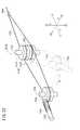
上記実施例は、例えば図57に示すような手術用ロボットシステム1700に適用してもよい。 The above embodiment may be applied to a
手術用ロボットシステム1700は、多関節型のロボットアーム1702と、コンソール1704とを有し、作業部1016はロボットアーム1702の先端に接続されている。ロボットアーム1702の先端には前記の医療用マニピュレータ1010と同じ機構が設けられている。ロボットアーム1702は、作業部1016を移動させる手段であればよく、据置型に限らず、例えば自律移動型でもよい。コンソール1704は、テーブル型、制御盤型等の構成を採りうる。 The
ロボットアーム1702は、独立的な6以上の関節(回転軸やスライド軸等)を有すると、作業部1016の位置及び向きを任意に設定できて好適である。先端の医療用マニピュレータ1010は、ロボットアーム1702の先端部1708と一体化している。医療用マニピュレータ1010は、前記のトリガレバー1032(図22参照)の代わりにモータ(人手によって操作する入力部に連動するアクチュエータ)1042を有し、該モータ1042がワイヤ1056(図22参照)又は駆動側連結プーリ1324(図36参照)を駆動する。 If the
ロボットアーム1702は、コンソール1704の作用下に動作し、プログラムによる自動動作や、コンソール1704に設けられたジョイスティック1706に倣った操作、及びこれらの複合的な動作をする構成にしてもよい。コンソール1704は、前記のコントローラ1045の機能を含んでいる。作業部1016には、前記の先端動作部1012(1012a〜1012f)が設けられている。 The
コンソール1704には、操作指令部としての2つのジョイスティック1706と、モニタ1710が設けられている。図示を省略するが、2つのジョイスティック1706により、2台のロボットアーム1702を個別に操作が可能である。2つのジョイスティック1706は、両手で操作しやすい位置に設けられている。モニタ1710には、軟性鏡による画像等の情報が表示される。 The
ジョイスティック1706は、上下動作、左右動作、捻り動作、及び傾動動作が可能であり、これらの動作に応じてロボットアーム1702を動かすことができる。ジョイスティック1706はマスターアームであってもよい。ロボットアーム1702とコンソール1704との間の通信手段は、有線、無線、ネットワーク又はこれらの組合わせでよい。 The
ジョイスティック1706には、トリガレバー1032が設けられており、該トリガレバー1032を操作することによりモータ1042を駆動可能である。 The
医療用マニピュレータの種類は、鉗子に限らず、例えば、鋏、結紮器、持針器や、電気メス、超音波メス、レーザメス等のメスであってもよい。また、その用途も、腹腔鏡下手術に使用されるものに限定されない。 The type of medical manipulator is not limited to forceps, and may be, for example, scissors such as scissors, ligators, needle holders, electric scalpels, ultrasonic scalpels, and laser scalpels. Moreover, the use is not limited to that used for laparoscopic surgery.
本発明に係る医療用マニピュレータシステムは、上述の実施の形態に限らず、本発明の要旨を逸脱することなく、種々の構成を採り得ることはもちろんである。 Of course, the medical manipulator system according to the present invention is not limited to the above-described embodiment, and various configurations can be adopted without departing from the gist of the present invention.
10、1010…医療用マニピュレータ 12…連結部
14、180、1012、1012a〜1012f…先端動作部
16、1014…操作部 18…伝達部材
22、1202、1212、1302…グリッパ
30…湾曲部 35…着脱部
62…ハンドル部 88…回転操作機構
90…回転用駆動源 130…屈曲操作機構
138…傾斜板 140、142…屈曲用駆動源
1032…トリガレバー 1040〜1042…モータ
1048…連結シャフト
1052、1054、1056…ワイヤ
1140、1140a、1140b…アイドルプーリ
1142、1142a、1142b…ガイドプーリ
1156、1156a、1156b…受動プーリ
1252、1252a、1252b…受動ワイヤDESCRIPTION OF
Claims (4)
Translated fromJapanese前記先端動作部を操作する操作部と、
前記操作部から延出するとともに前記先端動作部と前記操作部とを連結し、使用時に少なくとも一部が生体内に挿入される連結部と、
前記先端動作部の姿勢を変える姿勢変更機構と、
を備え、
前記エンドエフェクタの開閉動作は、前記操作部を操作者が操作することにより伝達部材である可撓性部材を含むエンドエフェクタ駆動機構を介して機械的に操作される一方、
前記姿勢変更機構の動作は、前記操作部を操作者が操作することにより作動するアクチュエータを介して操作され、
前記姿勢変更機構は、
前記エンドエフェクタの開閉軸よりも基端側の関節部で前記連結部の一部を屈曲させる屈曲機構と、
前記屈曲機構による屈曲箇所よりも先端側で前記先端動作部を前記連結部に対して軸周りに回転させる回転機構と、
を備え、
前記回転機構は、前記屈曲機構により前記先端動作部が前記連結部の軸方向と非平行に屈曲された状態で、前記先端動作部を前記屈曲した軸周りに回転可能に構成されており、
前記エンドエフェクタ駆動機構は、
進退する駆動部材と、
前記駆動部材に一部が接続された環状の前記可撓性部材と、
前記駆動部材より先端側で且つ前記関節部より基端側に設けられたアイドルプーリと、
前記先端動作部に、当該先端動作部の延在方向に進退可能に設けられた受動プーリと、
前記アイドルプーリと前記受動プーリとの間にある前記関節部に設けられたガイドプーリと、を含み、
前記エンドエフェクタは、前記受動プーリの進退動作に連動して開閉動作するものであり、
前記可撓性部材は、前記アイドルプーリの両側方を通り、前記受動プーリに巻き掛けられ、前記アイドルプーリと前記ガイドプーリとの間で交差しており、
前記アイドルプーリは、互いに逆方向に回転可能な第1層アイドルプーリと第2層アイドルプーリとが同軸上に並列して構成されており、
前記ガイドプーリは、互いに逆方向に回転可能な第1層ガイドプーリと第2層ガイドプーリとが同軸上に並列して構成されており、
前記可撓性部材における交差する一方部分は、前記第1層アイドルプーリと前記第1層ガイドプーリの外周面に接し、
前記可撓性部材における交差する他方部分は、前記第2層アイドルプーリと前記第2層ガイドプーリの外周面に接することを特徴とする医療用マニピュレータ。A tip working unit including an end effector capable of opening and closing;
An operating unit for operating the tip operating unit;
A connecting portion that extends from the operating portion and connects the distal end operating portion and the operating portion, and at least a portion of the connecting portion is inserted into the living body when used;
A posture changing mechanism for changing the posture of the distal end working unit;
With
While theopening and closing operation of theend effector is mechanically operated through anend effector driving mechanism including a flexible member that is a transmission member when an operator operates the operation unit,
The operation of the posture changing mechanism is operated via an actuator that is operated by an operator operating the operation unit,
The posture changing mechanism is
A bending mechanism that bends a part of the coupling portion ata joint portion onthe proximal sideof the opening / closing axis of the end effector;
A rotation mechanism that rotates the distal end working portion around the axis relative to the coupling portion on the distal end side with respect to a bending portion by the bending mechanism;
With
The rotating mechanism is configured to be able to rotate the tip operating portion around the bent axis in a state where the tip operating portion is bent non-parallel to the axial direction of the connecting portion by the bending mechanism.
The end effector drive mechanism is
A driving member that advances and retreats;
The annular flexible member partially connected to the drive member;
An idle pulley provided on the distal end side of the drive member and on the proximal end side of the joint portion;
A passive pulley provided on the distal end working portion so as to be capable of moving back and forth in the extending direction of the distal end working portion;
A guide pulley provided at the joint between the idle pulley and the passive pulley,
The end effector opens and closes in conjunction with the advance and retreat operation of the passive pulley.
The flexible member passes through both sides of the idle pulley, is wound around the passive pulley, and intersects between the idle pulley and the guide pulley,
The idle pulley is configured such that a first layer idle pulley and a second layer idle pulley that are rotatable in opposite directions are arranged in parallel on the same axis,
The guide pulley is configured such that a first layer guide pulley and a second layer guide pulley that are rotatable in opposite directions are arranged in parallel on the same axis,
One intersecting portion of the flexible member is in contact with the outer peripheral surfaces of the first layer idle pulley and the first layer guide pulley,
The medical manipulator characterized in thatthe other intersecting portions of the flexible members are in contact with outer peripheral surfaces of the second layer idle pulley and the second layer guide pulley .
前記連結部は、前記操作部に対して着脱自在に構成されていることを特徴とする医療用マニピュレータ。The medical manipulator according to claim 1, wherein
The said connection part is comprised with the said operation part so that attachment or detachment is possible, The medical manipulator characterized by the above-mentioned.
前記操作部は、操作者により回動されることで前記伝達部材を進退させるハンドル部を備えることを特徴とする医療用マニピュレータ。The medical manipulator according to claim 1 or 2,
The said operation part is provided with the handle part which advances and retracts the said transmission member by rotating by the operator, The medical manipulator characterized by the above-mentioned.
前記屈曲機構の前記アクチュエータは、操作部が操作されることにより前記連結部内を挿通する線材を進退させることを特徴とする医療用マニピュレータ。The medical manipulator according to any one of claims 1 to 3,
The said manipulator of the said bending mechanism is a medical manipulator characterized by advancing / retreating the wire which penetrates the inside of the said connection part by operating an operation part.
Priority Applications (9)
| Application Number | Priority Date | Filing Date | Title |
|---|---|---|---|
| JP2007283313AJP5364255B2 (en) | 2007-10-31 | 2007-10-31 | Medical manipulator |
| US11/939,287US9662131B2 (en) | 2007-10-31 | 2007-11-13 | Manipulator for medical use |
| CA2703920ACA2703920C (en) | 2007-10-31 | 2008-06-16 | Medical manipulator |
| KR1020107009484AKR101509275B1 (en) | 2007-10-31 | 2008-06-16 | Medical manipulator |
| PCT/JP2008/061374WO2009057347A1 (en) | 2007-10-31 | 2008-06-16 | Medical manipulator |
| BRPI0818311ABRPI0818311A2 (en) | 2007-10-31 | 2008-06-16 | medical manipulator |
| RU2010121772/14ARU2445933C2 (en) | 2007-10-31 | 2008-06-16 | Medical manipulator |
| CN200880110972.9ACN101820824B (en) | 2007-10-31 | 2008-06-16 | Medical manipulator |
| EP08777494.9AEP2211733B1 (en) | 2007-10-31 | 2008-06-16 | Medical manipulator |
Applications Claiming Priority (1)
| Application Number | Priority Date | Filing Date | Title |
|---|---|---|---|
| JP2007283313AJP5364255B2 (en) | 2007-10-31 | 2007-10-31 | Medical manipulator |
Publications (2)
| Publication Number | Publication Date |
|---|---|
| JP2009106606A JP2009106606A (en) | 2009-05-21 |
| JP5364255B2true JP5364255B2 (en) | 2013-12-11 |
Family
ID=39711103
Family Applications (1)
| Application Number | Title | Priority Date | Filing Date |
|---|---|---|---|
| JP2007283313AActiveJP5364255B2 (en) | 2007-10-31 | 2007-10-31 | Medical manipulator |
Country Status (9)
| Country | Link |
|---|---|
| US (1) | US9662131B2 (en) |
| EP (1) | EP2211733B1 (en) |
| JP (1) | JP5364255B2 (en) |
| KR (1) | KR101509275B1 (en) |
| CN (1) | CN101820824B (en) |
| BR (1) | BRPI0818311A2 (en) |
| CA (1) | CA2703920C (en) |
| RU (1) | RU2445933C2 (en) |
| WO (1) | WO2009057347A1 (en) |
Families Citing this family (795)
| Publication number | Priority date | Publication date | Assignee | Title |
|---|---|---|---|---|
| US7364577B2 (en) | 2002-02-11 | 2008-04-29 | Sherwood Services Ag | Vessel sealing system |
| ES2262639T3 (en) | 2001-04-06 | 2006-12-01 | Sherwood Services Ag | SHUTTER AND DIVIDER OF GLASSES WITH BUMPER MEMBERS N OCONDUCTIVES. |
| US11229472B2 (en) | 2001-06-12 | 2022-01-25 | Cilag Gmbh International | Modular battery powered handheld surgical instrument with multiple magnetic position sensors |
| US9060770B2 (en) | 2003-05-20 | 2015-06-23 | Ethicon Endo-Surgery, Inc. | Robotically-driven surgical instrument with E-beam driver |
| US20070084897A1 (en) | 2003-05-20 | 2007-04-19 | Shelton Frederick E Iv | Articulating surgical stapling instrument incorporating a two-piece e-beam firing mechanism |
| US7367976B2 (en) | 2003-11-17 | 2008-05-06 | Sherwood Services Ag | Bipolar forceps having monopolar extension |
| US8182501B2 (en) | 2004-02-27 | 2012-05-22 | Ethicon Endo-Surgery, Inc. | Ultrasonic surgical shears and method for sealing a blood vessel using same |
| US11890012B2 (en) | 2004-07-28 | 2024-02-06 | Cilag Gmbh International | Staple cartridge comprising cartridge body and attached support |
| US9072535B2 (en) | 2011-05-27 | 2015-07-07 | Ethicon Endo-Surgery, Inc. | Surgical stapling instruments with rotatable staple deployment arrangements |
| US11998198B2 (en) | 2004-07-28 | 2024-06-04 | Cilag Gmbh International | Surgical stapling instrument incorporating a two-piece E-beam firing mechanism |
| US8215531B2 (en) | 2004-07-28 | 2012-07-10 | Ethicon Endo-Surgery, Inc. | Surgical stapling instrument having a medical substance dispenser |
| US20060079879A1 (en) | 2004-10-08 | 2006-04-13 | Faller Craig N | Actuation mechanism for use with an ultrasonic surgical instrument |
| US7628791B2 (en) | 2005-08-19 | 2009-12-08 | Covidien Ag | Single action tissue sealer |
| US11246590B2 (en) | 2005-08-31 | 2022-02-15 | Cilag Gmbh International | Staple cartridge including staple drivers having different unfired heights |
| US7934630B2 (en) | 2005-08-31 | 2011-05-03 | Ethicon Endo-Surgery, Inc. | Staple cartridges for forming staples having differing formed staple heights |
| US9237891B2 (en) | 2005-08-31 | 2016-01-19 | Ethicon Endo-Surgery, Inc. | Robotically-controlled surgical stapling devices that produce formed staples having different lengths |
| US10159482B2 (en) | 2005-08-31 | 2018-12-25 | Ethicon Llc | Fastener cartridge assembly comprising a fixed anvil and different staple heights |
| US8800838B2 (en) | 2005-08-31 | 2014-08-12 | Ethicon Endo-Surgery, Inc. | Robotically-controlled cable-based surgical end effectors |
| US11484312B2 (en) | 2005-08-31 | 2022-11-01 | Cilag Gmbh International | Staple cartridge comprising a staple driver arrangement |
| US7673781B2 (en) | 2005-08-31 | 2010-03-09 | Ethicon Endo-Surgery, Inc. | Surgical stapling device with staple driver that supports multiple wire diameter staples |
| US7669746B2 (en) | 2005-08-31 | 2010-03-02 | Ethicon Endo-Surgery, Inc. | Staple cartridges for forming staples having differing formed staple heights |
| US20070191713A1 (en) | 2005-10-14 | 2007-08-16 | Eichmann Stephen E | Ultrasonic device for cutting and coagulating |
| US20070106317A1 (en) | 2005-11-09 | 2007-05-10 | Shelton Frederick E Iv | Hydraulically and electrically actuated articulation joints for surgical instruments |
| US7621930B2 (en) | 2006-01-20 | 2009-11-24 | Ethicon Endo-Surgery, Inc. | Ultrasound medical instrument having a medical ultrasonic blade |
| US8708213B2 (en) | 2006-01-31 | 2014-04-29 | Ethicon Endo-Surgery, Inc. | Surgical instrument having a feedback system |
| US8161977B2 (en) | 2006-01-31 | 2012-04-24 | Ethicon Endo-Surgery, Inc. | Accessing data stored in a memory of a surgical instrument |
| US11224427B2 (en) | 2006-01-31 | 2022-01-18 | Cilag Gmbh International | Surgical stapling system including a console and retraction assembly |
| US9861359B2 (en) | 2006-01-31 | 2018-01-09 | Ethicon Llc | Powered surgical instruments with firing system lockout arrangements |
| US20110024477A1 (en) | 2009-02-06 | 2011-02-03 | Hall Steven G | Driven Surgical Stapler Improvements |
| US11278279B2 (en) | 2006-01-31 | 2022-03-22 | Cilag Gmbh International | Surgical instrument assembly |
| US20120292367A1 (en) | 2006-01-31 | 2012-11-22 | Ethicon Endo-Surgery, Inc. | Robotically-controlled end effector |
| US11793518B2 (en) | 2006-01-31 | 2023-10-24 | Cilag Gmbh International | Powered surgical instruments with firing system lockout arrangements |
| US7845537B2 (en) | 2006-01-31 | 2010-12-07 | Ethicon Endo-Surgery, Inc. | Surgical instrument having recording capabilities |
| US7753904B2 (en) | 2006-01-31 | 2010-07-13 | Ethicon Endo-Surgery, Inc. | Endoscopic surgical instrument with a handle that can articulate with respect to the shaft |
| US8820603B2 (en) | 2006-01-31 | 2014-09-02 | Ethicon Endo-Surgery, Inc. | Accessing data stored in a memory of a surgical instrument |
| US8186555B2 (en) | 2006-01-31 | 2012-05-29 | Ethicon Endo-Surgery, Inc. | Motor-driven surgical cutting and fastening instrument with mechanical closure system |
| US20110295295A1 (en) | 2006-01-31 | 2011-12-01 | Ethicon Endo-Surgery, Inc. | Robotically-controlled surgical instrument having recording capabilities |
| US8763879B2 (en) | 2006-01-31 | 2014-07-01 | Ethicon Endo-Surgery, Inc. | Accessing data stored in a memory of surgical instrument |
| US8236010B2 (en) | 2006-03-23 | 2012-08-07 | Ethicon Endo-Surgery, Inc. | Surgical fastener and cutter with mimicking end effector |
| US8992422B2 (en) | 2006-03-23 | 2015-03-31 | Ethicon Endo-Surgery, Inc. | Robotically-controlled endoscopic accessory channel |
| WO2007149559A2 (en) | 2006-06-22 | 2007-12-27 | Board Of Regents Of The University Of Nebraska | Magnetically coupleable robotic devices and related methods |
| US9579088B2 (en) | 2007-02-20 | 2017-02-28 | Board Of Regents Of The University Of Nebraska | Methods, systems, and devices for surgical visualization and device manipulation |
| US8679096B2 (en) | 2007-06-21 | 2014-03-25 | Board Of Regents Of The University Of Nebraska | Multifunctional operational component for robotic devices |
| US8322455B2 (en) | 2006-06-27 | 2012-12-04 | Ethicon Endo-Surgery, Inc. | Manually driven surgical cutting and fastening instrument |
| US7506791B2 (en) | 2006-09-29 | 2009-03-24 | Ethicon Endo-Surgery, Inc. | Surgical stapling instrument with mechanical mechanism for limiting maximum tissue compression |
| US10130359B2 (en) | 2006-09-29 | 2018-11-20 | Ethicon Llc | Method for forming a staple |
| US10568652B2 (en) | 2006-09-29 | 2020-02-25 | Ethicon Llc | Surgical staples having attached drivers of different heights and stapling instruments for deploying the same |
| US11980366B2 (en) | 2006-10-03 | 2024-05-14 | Cilag Gmbh International | Surgical instrument |
| US8632535B2 (en) | 2007-01-10 | 2014-01-21 | Ethicon Endo-Surgery, Inc. | Interlock and surgical instrument including same |
| US8652120B2 (en)* | 2007-01-10 | 2014-02-18 | Ethicon Endo-Surgery, Inc. | Surgical instrument with wireless communication between control unit and sensor transponders |
| US11291441B2 (en) | 2007-01-10 | 2022-04-05 | Cilag Gmbh International | Surgical instrument with wireless communication between control unit and remote sensor |
| US8684253B2 (en) | 2007-01-10 | 2014-04-01 | Ethicon Endo-Surgery, Inc. | Surgical instrument with wireless communication between a control unit of a robotic system and remote sensor |
| US8459520B2 (en) | 2007-01-10 | 2013-06-11 | Ethicon Endo-Surgery, Inc. | Surgical instrument with wireless communication between control unit and remote sensor |
| US11039836B2 (en) | 2007-01-11 | 2021-06-22 | Cilag Gmbh International | Staple cartridge for use with a surgical stapling instrument |
| US20080169333A1 (en) | 2007-01-11 | 2008-07-17 | Shelton Frederick E | Surgical stapler end effector with tapered distal end |
| US7673782B2 (en) | 2007-03-15 | 2010-03-09 | Ethicon Endo-Surgery, Inc. | Surgical stapling instrument having a releasable buttress material |
| US8226675B2 (en) | 2007-03-22 | 2012-07-24 | Ethicon Endo-Surgery, Inc. | Surgical instruments |
| US8142461B2 (en) | 2007-03-22 | 2012-03-27 | Ethicon Endo-Surgery, Inc. | Surgical instruments |
| US8911460B2 (en) | 2007-03-22 | 2014-12-16 | Ethicon Endo-Surgery, Inc. | Ultrasonic surgical instruments |
| US8057498B2 (en) | 2007-11-30 | 2011-11-15 | Ethicon Endo-Surgery, Inc. | Ultrasonic surgical instrument blades |
| US8893946B2 (en) | 2007-03-28 | 2014-11-25 | Ethicon Endo-Surgery, Inc. | Laparoscopic tissue thickness and clamp load measuring devices |
| US8931682B2 (en) | 2007-06-04 | 2015-01-13 | Ethicon Endo-Surgery, Inc. | Robotically-controlled shaft based rotary drive systems for surgical instruments |
| US8534528B2 (en) | 2007-06-04 | 2013-09-17 | Ethicon Endo-Surgery, Inc. | Surgical instrument having a multiple rate directional switching mechanism |
| US11564682B2 (en) | 2007-06-04 | 2023-01-31 | Cilag Gmbh International | Surgical stapler device |
| US8408439B2 (en) | 2007-06-22 | 2013-04-02 | Ethicon Endo-Surgery, Inc. | Surgical stapling instrument with an articulatable end effector |
| US7753245B2 (en) | 2007-06-22 | 2010-07-13 | Ethicon Endo-Surgery, Inc. | Surgical stapling instruments |
| US11849941B2 (en) | 2007-06-29 | 2023-12-26 | Cilag Gmbh International | Staple cartridge having staple cavities extending at a transverse angle relative to a longitudinal cartridge axis |
| US8343171B2 (en) | 2007-07-12 | 2013-01-01 | Board Of Regents Of The University Of Nebraska | Methods and systems of actuation in robotic devices |
| US8523889B2 (en) | 2007-07-27 | 2013-09-03 | Ethicon Endo-Surgery, Inc. | Ultrasonic end effectors with increased active length |
| US8882791B2 (en) | 2007-07-27 | 2014-11-11 | Ethicon Endo-Surgery, Inc. | Ultrasonic surgical instruments |
| US8808319B2 (en) | 2007-07-27 | 2014-08-19 | Ethicon Endo-Surgery, Inc. | Surgical instruments |
| US9044261B2 (en) | 2007-07-31 | 2015-06-02 | Ethicon Endo-Surgery, Inc. | Temperature controlled ultrasonic surgical instruments |
| US8430898B2 (en) | 2007-07-31 | 2013-04-30 | Ethicon Endo-Surgery, Inc. | Ultrasonic surgical instruments |
| US8512365B2 (en) | 2007-07-31 | 2013-08-20 | Ethicon Endo-Surgery, Inc. | Surgical instruments |
| JP2010536435A (en) | 2007-08-15 | 2010-12-02 | ボード オブ リージェンツ オブ ザ ユニバーシティ オブ ネブラスカ | Medical inflation, attachment and delivery devices and associated methods |
| EP2217157A2 (en) | 2007-10-05 | 2010-08-18 | Ethicon Endo-Surgery, Inc. | Ergonomic surgical instruments |
| JP5128904B2 (en)* | 2007-10-31 | 2013-01-23 | 株式会社東芝 | manipulator |
| US10010339B2 (en) | 2007-11-30 | 2018-07-03 | Ethicon Llc | Ultrasonic surgical blades |
| US8561870B2 (en) | 2008-02-13 | 2013-10-22 | Ethicon Endo-Surgery, Inc. | Surgical stapling instrument |
| US7866527B2 (en) | 2008-02-14 | 2011-01-11 | Ethicon Endo-Surgery, Inc. | Surgical stapling apparatus with interlockable firing system |
| US9179912B2 (en) | 2008-02-14 | 2015-11-10 | Ethicon Endo-Surgery, Inc. | Robotically-controlled motorized surgical cutting and fastening instrument |
| US8752749B2 (en) | 2008-02-14 | 2014-06-17 | Ethicon Endo-Surgery, Inc. | Robotically-controlled disposable motor-driven loading unit |
| US8657174B2 (en) | 2008-02-14 | 2014-02-25 | Ethicon Endo-Surgery, Inc. | Motorized surgical cutting and fastening instrument having handle based power source |
| US8584919B2 (en) | 2008-02-14 | 2013-11-19 | Ethicon Endo-Sugery, Inc. | Surgical stapling apparatus with load-sensitive firing mechanism |
| US8758391B2 (en) | 2008-02-14 | 2014-06-24 | Ethicon Endo-Surgery, Inc. | Interchangeable tools for surgical instruments |
| US8622274B2 (en) | 2008-02-14 | 2014-01-07 | Ethicon Endo-Surgery, Inc. | Motorized cutting and fastening instrument having control circuit for optimizing battery usage |
| US8573465B2 (en) | 2008-02-14 | 2013-11-05 | Ethicon Endo-Surgery, Inc. | Robotically-controlled surgical end effector system with rotary actuated closure systems |
| US11986183B2 (en) | 2008-02-14 | 2024-05-21 | Cilag Gmbh International | Surgical cutting and fastening instrument comprising a plurality of sensors to measure an electrical parameter |
| JP5410110B2 (en) | 2008-02-14 | 2014-02-05 | エシコン・エンド−サージェリィ・インコーポレイテッド | Surgical cutting / fixing instrument with RF electrode |
| US8636736B2 (en) | 2008-02-14 | 2014-01-28 | Ethicon Endo-Surgery, Inc. | Motorized surgical cutting and fastening instrument |
| US7819298B2 (en) | 2008-02-14 | 2010-10-26 | Ethicon Endo-Surgery, Inc. | Surgical stapling apparatus with control features operable with one hand |
| US7793812B2 (en) | 2008-02-14 | 2010-09-14 | Ethicon Endo-Surgery, Inc. | Disposable motor-driven loading unit for use with a surgical cutting and stapling apparatus |
| US11272927B2 (en) | 2008-02-15 | 2022-03-15 | Cilag Gmbh International | Layer arrangements for surgical staple cartridges |
| US9585657B2 (en) | 2008-02-15 | 2017-03-07 | Ethicon Endo-Surgery, Llc | Actuator for releasing a layer of material from a surgical end effector |
| US20100016883A1 (en)* | 2008-07-18 | 2010-01-21 | Christoudias George C | Double grasper and trigger control mechanism |
| US9089360B2 (en) | 2008-08-06 | 2015-07-28 | Ethicon Endo-Surgery, Inc. | Devices and techniques for cutting and coagulating tissue |
| PL3476312T3 (en) | 2008-09-19 | 2024-03-11 | Ethicon Llc | Surgical stapler with apparatus for adjusting staple height |
| US7954686B2 (en) | 2008-09-19 | 2011-06-07 | Ethicon Endo-Surgery, Inc. | Surgical stapler with apparatus for adjusting staple height |
| US9005230B2 (en) | 2008-09-23 | 2015-04-14 | Ethicon Endo-Surgery, Inc. | Motorized surgical instrument |
| US11648005B2 (en) | 2008-09-23 | 2023-05-16 | Cilag Gmbh International | Robotically-controlled motorized surgical instrument with an end effector |
| US9050083B2 (en) | 2008-09-23 | 2015-06-09 | Ethicon Endo-Surgery, Inc. | Motorized surgical instrument |
| US8210411B2 (en) | 2008-09-23 | 2012-07-03 | Ethicon Endo-Surgery, Inc. | Motor-driven surgical cutting instrument |
| US9386983B2 (en) | 2008-09-23 | 2016-07-12 | Ethicon Endo-Surgery, Llc | Robotically-controlled motorized surgical instrument |
| US8142473B2 (en) | 2008-10-03 | 2012-03-27 | Tyco Healthcare Group Lp | Method of transferring rotational motion in an articulating surgical instrument |
| US8608045B2 (en) | 2008-10-10 | 2013-12-17 | Ethicon Endo-Sugery, Inc. | Powered surgical cutting and stapling apparatus with manually retractable firing system |
| US8114122B2 (en) | 2009-01-13 | 2012-02-14 | Tyco Healthcare Group Lp | Apparatus, system, and method for performing an electrosurgical procedure |
| US8523900B2 (en)* | 2009-02-03 | 2013-09-03 | Terumo Kabushiki Kaisha | Medical manipulator |
| US8517239B2 (en) | 2009-02-05 | 2013-08-27 | Ethicon Endo-Surgery, Inc. | Surgical stapling instrument comprising a magnetic element driver |
| US8453907B2 (en) | 2009-02-06 | 2013-06-04 | Ethicon Endo-Surgery, Inc. | Motor driven surgical fastener device with cutting member reversing mechanism |
| US8444036B2 (en) | 2009-02-06 | 2013-05-21 | Ethicon Endo-Surgery, Inc. | Motor driven surgical fastener device with mechanisms for adjusting a tissue gap within the end effector |
| RU2525225C2 (en) | 2009-02-06 | 2014-08-10 | Этикон Эндо-Серджери, Инк. | Improvement of drive surgical suturing instrument |
| US8187273B2 (en) | 2009-05-07 | 2012-05-29 | Tyco Healthcare Group Lp | Apparatus, system, and method for performing an electrosurgical procedure |
| US9700339B2 (en) | 2009-05-20 | 2017-07-11 | Ethicon Endo-Surgery, Inc. | Coupling arrangements and methods for attaching tools to ultrasonic surgical instruments |
| US8650728B2 (en) | 2009-06-24 | 2014-02-18 | Ethicon Endo-Surgery, Inc. | Method of assembling a transducer for a surgical instrument |
| US8246618B2 (en) | 2009-07-08 | 2012-08-21 | Tyco Healthcare Group Lp | Electrosurgical jaws with offset knife |
| US8663220B2 (en) | 2009-07-15 | 2014-03-04 | Ethicon Endo-Surgery, Inc. | Ultrasonic surgical instruments |
| US20110015648A1 (en)* | 2009-07-16 | 2011-01-20 | Hansen Medical, Inc. | Endoscopic robotic catheter system |
| US20110015483A1 (en)* | 2009-07-16 | 2011-01-20 | Federico Barbagli | Endoscopic robotic catheter system |
| WO2011008922A2 (en)* | 2009-07-16 | 2011-01-20 | Hansen Medical, Inc. | Endoscopic robotic catheter system |
| US20110015484A1 (en)* | 2009-07-16 | 2011-01-20 | Alvarez Jeffrey B | Endoscopic robotic catheter system |
| EP2478854B8 (en) | 2009-09-15 | 2019-03-06 | Olympus Corporation | Endoscope treatment tool |
| US8133254B2 (en) | 2009-09-18 | 2012-03-13 | Tyco Healthcare Group Lp | In vivo attachable and detachable end effector assembly and laparoscopic surgical instrument and methods therefor |
| US8112871B2 (en) | 2009-09-28 | 2012-02-14 | Tyco Healthcare Group Lp | Method for manufacturing electrosurgical seal plates |
| US9168054B2 (en) | 2009-10-09 | 2015-10-27 | Ethicon Endo-Surgery, Inc. | Surgical generator for ultrasonic and electrosurgical devices |
| US11090104B2 (en) | 2009-10-09 | 2021-08-17 | Cilag Gmbh International | Surgical generator for ultrasonic and electrosurgical devices |
| US9050093B2 (en) | 2009-10-09 | 2015-06-09 | Ethicon Endo-Surgery, Inc. | Surgical generator for ultrasonic and electrosurgical devices |
| US10172669B2 (en) | 2009-10-09 | 2019-01-08 | Ethicon Llc | Surgical instrument comprising an energy trigger lockout |
| USRE47996E1 (en) | 2009-10-09 | 2020-05-19 | Ethicon Llc | Surgical generator for ultrasonic and electrosurgical devices |
| US10441345B2 (en) | 2009-10-09 | 2019-10-15 | Ethicon Llc | Surgical generator for ultrasonic and electrosurgical devices |
| ES2388867B1 (en)* | 2009-10-27 | 2013-09-18 | Universitat Politècnica De Catalunya | MINIMALLY INVASIVE LAPAROSCOPIC SURGERY CLAMPS. |
| EP2498710B1 (en) | 2009-11-13 | 2018-05-16 | Intuitive Surgical Operations, Inc. | Motor interface for parallel drive shafts within an independently rotating member |
| US20110118708A1 (en) | 2009-11-13 | 2011-05-19 | Intuitive Surgical Operations, Inc. | Double universal joint |
| EP2467065B1 (en) | 2009-11-13 | 2020-01-08 | Intuitive Surgical Operations, Inc. | End effector with redundant closing mechanisms |
| KR102152042B1 (en) | 2009-11-13 | 2020-09-04 | 인튜어티브 서지컬 오퍼레이션즈 인코포레이티드 | Surgical tool with a compact wrist |
| US8851354B2 (en) | 2009-12-24 | 2014-10-07 | Ethicon Endo-Surgery, Inc. | Surgical cutting instrument that analyzes tissue thickness |
| US8220688B2 (en) | 2009-12-24 | 2012-07-17 | Ethicon Endo-Surgery, Inc. | Motor-driven surgical cutting instrument with electric actuator directional control assembly |
| KR101146407B1 (en) | 2009-12-30 | 2012-05-17 | 국립암센터 | Manipulator for surgical operation |
| US8469981B2 (en) | 2010-02-11 | 2013-06-25 | Ethicon Endo-Surgery, Inc. | Rotatable cutting implement arrangements for ultrasonic surgical instruments |
| US8579928B2 (en) | 2010-02-11 | 2013-11-12 | Ethicon Endo-Surgery, Inc. | Outer sheath and blade arrangements for ultrasonic surgical instruments |
| US8486096B2 (en) | 2010-02-11 | 2013-07-16 | Ethicon Endo-Surgery, Inc. | Dual purpose surgical instrument for cutting and coagulating tissue |
| US8961547B2 (en) | 2010-02-11 | 2015-02-24 | Ethicon Endo-Surgery, Inc. | Ultrasonic surgical instruments with moving cutting implement |
| US8951272B2 (en) | 2010-02-11 | 2015-02-10 | Ethicon Endo-Surgery, Inc. | Seal arrangements for ultrasonically powered surgical instruments |
| JP5875973B2 (en)* | 2010-03-15 | 2016-03-02 | カール シュトルツ ゲゼルシャフト ミット ベシュレンクテル ハフツング ウント コンパニー コマンディートゲゼルシャフト | Medical manipulator |
| US8834518B2 (en) | 2010-04-12 | 2014-09-16 | Ethicon Endo-Surgery, Inc. | Electrosurgical cutting and sealing instruments with cam-actuated jaws |
| GB2480498A (en) | 2010-05-21 | 2011-11-23 | Ethicon Endo Surgery Inc | Medical device comprising RF circuitry |
| US11278345B2 (en)* | 2010-05-25 | 2022-03-22 | Covidien Lp | Accurate jaw closure force in a catheter based instrument |
| US8540749B2 (en) | 2010-06-02 | 2013-09-24 | Covidien Lp | Apparatus for performing an electrosurgical procedure |
| JP4965005B2 (en)* | 2010-06-28 | 2012-07-04 | オリンパスメディカルシステムズ株式会社 | Endoscopy forceps |
| US8795327B2 (en) | 2010-07-22 | 2014-08-05 | Ethicon Endo-Surgery, Inc. | Electrosurgical instrument with separate closure and cutting members |
| US9192431B2 (en) | 2010-07-23 | 2015-11-24 | Ethicon Endo-Surgery, Inc. | Electrosurgical cutting and sealing instrument |
| US8783543B2 (en) | 2010-07-30 | 2014-07-22 | Ethicon Endo-Surgery, Inc. | Tissue acquisition arrangements and methods for surgical stapling devices |
| CN101933825A (en)* | 2010-08-20 | 2011-01-05 | 上海祥秀医药科技有限公司 | Needle holder used for surgical minimally invasive surgery |
| US8360296B2 (en) | 2010-09-09 | 2013-01-29 | Ethicon Endo-Surgery, Inc. | Surgical stapling head assembly with firing lockout for a surgical stapler |
| US20120078244A1 (en) | 2010-09-24 | 2012-03-29 | Worrell Barry C | Control features for articulating surgical device |
| US11812965B2 (en) | 2010-09-30 | 2023-11-14 | Cilag Gmbh International | Layer of material for a surgical end effector |
| US9220501B2 (en) | 2010-09-30 | 2015-12-29 | Ethicon Endo-Surgery, Inc. | Tissue thickness compensators |
| US9332974B2 (en) | 2010-09-30 | 2016-05-10 | Ethicon Endo-Surgery, Llc | Layered tissue thickness compensator |
| US9386988B2 (en) | 2010-09-30 | 2016-07-12 | Ethicon End-Surgery, LLC | Retainer assembly including a tissue thickness compensator |
| US9055941B2 (en) | 2011-09-23 | 2015-06-16 | Ethicon Endo-Surgery, Inc. | Staple cartridge including collapsible deck |
| US9277919B2 (en) | 2010-09-30 | 2016-03-08 | Ethicon Endo-Surgery, Llc | Tissue thickness compensator comprising fibers to produce a resilient load |
| RU2013119928A (en) | 2010-09-30 | 2014-11-10 | Этикон Эндо-Серджери, Инк. | A STAPLING SYSTEM CONTAINING A RETAINING MATRIX AND A LEVELING MATRIX |
| US9016542B2 (en) | 2010-09-30 | 2015-04-28 | Ethicon Endo-Surgery, Inc. | Staple cartridge comprising compressible distortion resistant components |
| US10945731B2 (en) | 2010-09-30 | 2021-03-16 | Ethicon Llc | Tissue thickness compensator comprising controlled release and expansion |
| US9351730B2 (en) | 2011-04-29 | 2016-05-31 | Ethicon Endo-Surgery, Llc | Tissue thickness compensator comprising channels |
| US9314246B2 (en) | 2010-09-30 | 2016-04-19 | Ethicon Endo-Surgery, Llc | Tissue stapler having a thickness compensator incorporating an anti-inflammatory agent |
| US9364233B2 (en) | 2010-09-30 | 2016-06-14 | Ethicon Endo-Surgery, Llc | Tissue thickness compensators for circular surgical staplers |
| US9788834B2 (en) | 2010-09-30 | 2017-10-17 | Ethicon Llc | Layer comprising deployable attachment members |
| US9629814B2 (en) | 2010-09-30 | 2017-04-25 | Ethicon Endo-Surgery, Llc | Tissue thickness compensator configured to redistribute compressive forces |
| US11298125B2 (en) | 2010-09-30 | 2022-04-12 | Cilag Gmbh International | Tissue stapler having a thickness compensator |
| US9301752B2 (en) | 2010-09-30 | 2016-04-05 | Ethicon Endo-Surgery, Llc | Tissue thickness compensator comprising a plurality of capsules |
| US9301753B2 (en) | 2010-09-30 | 2016-04-05 | Ethicon Endo-Surgery, Llc | Expandable tissue thickness compensator |
| US11925354B2 (en) | 2010-09-30 | 2024-03-12 | Cilag Gmbh International | Staple cartridge comprising staples positioned within a compressible portion thereof |
| US12213666B2 (en) | 2010-09-30 | 2025-02-04 | Cilag Gmbh International | Tissue thickness compensator comprising layers |
| US9307989B2 (en) | 2012-03-28 | 2016-04-12 | Ethicon Endo-Surgery, Llc | Tissue stapler having a thickness compensator incorportating a hydrophobic agent |
| US9232941B2 (en) | 2010-09-30 | 2016-01-12 | Ethicon Endo-Surgery, Inc. | Tissue thickness compensator comprising a reservoir |
| US8893949B2 (en) | 2010-09-30 | 2014-11-25 | Ethicon Endo-Surgery, Inc. | Surgical stapler with floating anvil |
| US8979890B2 (en) | 2010-10-01 | 2015-03-17 | Ethicon Endo-Surgery, Inc. | Surgical instrument with jaw member |
| US8695866B2 (en) | 2010-10-01 | 2014-04-15 | Ethicon Endo-Surgery, Inc. | Surgical instrument having a power control circuit |
| WO2012073789A1 (en)* | 2010-11-30 | 2012-06-07 | オリンパス株式会社 | Master control input device and master-slave manipulator |
| US9113940B2 (en) | 2011-01-14 | 2015-08-25 | Covidien Lp | Trigger lockout and kickback mechanism for surgical instruments |
| US9730717B2 (en) | 2011-02-03 | 2017-08-15 | Karl Storz Gmbh & Co. Kg | Medical manipulator system |
| DE102011011497A1 (en)* | 2011-02-17 | 2012-08-23 | Kuka Roboter Gmbh | Surgical instrument |
| US9211122B2 (en) | 2011-03-14 | 2015-12-15 | Ethicon Endo-Surgery, Inc. | Surgical access devices with anvil introduction and specimen retrieval structures |
| AU2012250197B2 (en) | 2011-04-29 | 2017-08-10 | Ethicon Endo-Surgery, Inc. | Staple cartridge comprising staples positioned within a compressible portion thereof |
| US11207064B2 (en) | 2011-05-27 | 2021-12-28 | Cilag Gmbh International | Automated end effector component reloading system for use with a robotic system |
| US9913694B2 (en) | 2011-05-31 | 2018-03-13 | Intuitive Surgical Operations, Inc. | Grip force control in a robotic surgical instrument |
| JP6174017B2 (en) | 2011-06-10 | 2017-08-02 | ボード オブ リージェンツ オブ ザ ユニバーシティ オブ ネブラスカ | In vivo vascular seal end effector and in vivo robotic device |
| WO2013009887A1 (en) | 2011-07-11 | 2013-01-17 | Board Of Regents Of The University Of Nebraska | Robotic surgical devices, systems and related methods |
| US9259265B2 (en) | 2011-07-22 | 2016-02-16 | Ethicon Endo-Surgery, Llc | Surgical instruments for tensioning tissue |
| WO2013025831A2 (en)* | 2011-08-15 | 2013-02-21 | Intuitive Surgical Operations, Inc. | Medical instrument with flexible jaw and/or flexible wrist mechanisms |
| US9044243B2 (en) | 2011-08-30 | 2015-06-02 | Ethcon Endo-Surgery, Inc. | Surgical cutting and fastening device with descendible second trigger arrangement |
| US9113938B2 (en) | 2011-09-09 | 2015-08-25 | Covidien Lp | Apparatus for performing electrosurgical procedures having a spring mechanism associated with the jaw members |
| US9050084B2 (en) | 2011-09-23 | 2015-06-09 | Ethicon Endo-Surgery, Inc. | Staple cartridge including collapsible deck arrangement |
| WO2013052137A2 (en) | 2011-10-03 | 2013-04-11 | Board Of Regents Of The University Of Nebraska | Robotic surgical devices, systems and related methods |
| US9333025B2 (en) | 2011-10-24 | 2016-05-10 | Ethicon Endo-Surgery, Llc | Battery initialization clip |
| US8968312B2 (en) | 2011-11-16 | 2015-03-03 | Covidien Lp | Surgical device with powered articulation wrist rotation |
| WO2013106569A2 (en) | 2012-01-10 | 2013-07-18 | Board Of Regents Of The University Of Nebraska | Methods, systems, and devices for surgical access and insertion |
| RU2491161C1 (en)* | 2012-01-10 | 2013-08-27 | Олег Владимирович Галимов | Robotic system for minimally invasive surgery |
| USD680220S1 (en) | 2012-01-12 | 2013-04-16 | Coviden IP | Slider handle for laparoscopic device |
| JP5856865B2 (en)* | 2012-02-08 | 2016-02-10 | オリンパス株式会社 | Electric bending endoscope |
| WO2013119545A1 (en) | 2012-02-10 | 2013-08-15 | Ethicon-Endo Surgery, Inc. | Robotically controlled surgical instrument |
| US9044230B2 (en) | 2012-02-13 | 2015-06-02 | Ethicon Endo-Surgery, Inc. | Surgical cutting and fastening instrument with apparatus for determining cartridge and firing motion status |
| US9198662B2 (en) | 2012-03-28 | 2015-12-01 | Ethicon Endo-Surgery, Inc. | Tissue thickness compensator having improved visibility |
| BR112014024098B1 (en) | 2012-03-28 | 2021-05-25 | Ethicon Endo-Surgery, Inc. | staple cartridge |
| JP6224070B2 (en) | 2012-03-28 | 2017-11-01 | エシコン・エンド−サージェリィ・インコーポレイテッドEthicon Endo−Surgery,Inc. | Retainer assembly including tissue thickness compensator |
| MX358135B (en) | 2012-03-28 | 2018-08-06 | Ethicon Endo Surgery Inc | Tissue thickness compensator comprising a plurality of layers. |
| US9237921B2 (en) | 2012-04-09 | 2016-01-19 | Ethicon Endo-Surgery, Inc. | Devices and techniques for cutting and coagulating tissue |
| US9226766B2 (en) | 2012-04-09 | 2016-01-05 | Ethicon Endo-Surgery, Inc. | Serial communication protocol for medical device |
| US9241731B2 (en) | 2012-04-09 | 2016-01-26 | Ethicon Endo-Surgery, Inc. | Rotatable electrical connection for ultrasonic surgical instruments |
| US9439668B2 (en) | 2012-04-09 | 2016-09-13 | Ethicon Endo-Surgery, Llc | Switch arrangements for ultrasonic surgical instruments |
| US9724118B2 (en) | 2012-04-09 | 2017-08-08 | Ethicon Endo-Surgery, Llc | Techniques for cutting and coagulating tissue for ultrasonic surgical instruments |
| JP5990026B2 (en)* | 2012-04-12 | 2016-09-07 | カール シュトルツ ゲゼルシャフト ミット ベシュレンクテル ハフツング ウント コンパニー コマンディートゲゼルシャフト | Medical manipulator |
| JP5921943B2 (en)* | 2012-04-12 | 2016-05-24 | カール シュトルツ ゲゼルシャフト ミット ベシュレンクテル ハフツング ウント コンパニー コマンディートゲゼルシャフト | Medical manipulator |
| EP2844181B1 (en) | 2012-05-01 | 2021-03-10 | Board of Regents of the University of Nebraska | Single site robotic device and related systems |
| US9101358B2 (en) | 2012-06-15 | 2015-08-11 | Ethicon Endo-Surgery, Inc. | Articulatable surgical instrument comprising a firing drive |
| EP3189948B1 (en) | 2012-06-22 | 2018-10-17 | Board of Regents of the University of Nebraska | Local control robotic surgical devices |
| US9282974B2 (en) | 2012-06-28 | 2016-03-15 | Ethicon Endo-Surgery, Llc | Empty clip cartridge lockout |
| US11278284B2 (en) | 2012-06-28 | 2022-03-22 | Cilag Gmbh International | Rotary drive arrangements for surgical instruments |
| US9101385B2 (en) | 2012-06-28 | 2015-08-11 | Ethicon Endo-Surgery, Inc. | Electrode connections for rotary driven surgical tools |
| US9561038B2 (en) | 2012-06-28 | 2017-02-07 | Ethicon Endo-Surgery, Llc | Interchangeable clip applier |
| BR112014032776B1 (en) | 2012-06-28 | 2021-09-08 | Ethicon Endo-Surgery, Inc | SURGICAL INSTRUMENT SYSTEM AND SURGICAL KIT FOR USE WITH A SURGICAL INSTRUMENT SYSTEM |
| US9408606B2 (en) | 2012-06-28 | 2016-08-09 | Ethicon Endo-Surgery, Llc | Robotically powered surgical device with manually-actuatable reversing system |
| US9125662B2 (en) | 2012-06-28 | 2015-09-08 | Ethicon Endo-Surgery, Inc. | Multi-axis articulating and rotating surgical tools |
| US12383267B2 (en) | 2012-06-28 | 2025-08-12 | Cilag Gmbh International | Robotically powered surgical device with manually-actuatable reversing system |
| US9028494B2 (en) | 2012-06-28 | 2015-05-12 | Ethicon Endo-Surgery, Inc. | Interchangeable end effector coupling arrangement |
| US20140005705A1 (en) | 2012-06-29 | 2014-01-02 | Ethicon Endo-Surgery, Inc. | Surgical instruments with articulating shafts |
| US9289256B2 (en) | 2012-06-28 | 2016-03-22 | Ethicon Endo-Surgery, Llc | Surgical end effectors having angled tissue-contacting surfaces |
| US8747238B2 (en) | 2012-06-28 | 2014-06-10 | Ethicon Endo-Surgery, Inc. | Rotary drive shaft assemblies for surgical instruments with articulatable end effectors |
| US20140005718A1 (en) | 2012-06-28 | 2014-01-02 | Ethicon Endo-Surgery, Inc. | Multi-functional powered surgical device with external dissection features |
| US9072536B2 (en) | 2012-06-28 | 2015-07-07 | Ethicon Endo-Surgery, Inc. | Differential locking arrangements for rotary powered surgical instruments |
| US9119657B2 (en) | 2012-06-28 | 2015-09-01 | Ethicon Endo-Surgery, Inc. | Rotary actuatable closure arrangement for surgical end effector |
| JP6290201B2 (en) | 2012-06-28 | 2018-03-07 | エシコン・エンド−サージェリィ・インコーポレイテッドEthicon Endo−Surgery,Inc. | Lockout for empty clip cartridge |
| US20140001231A1 (en) | 2012-06-28 | 2014-01-02 | Ethicon Endo-Surgery, Inc. | Firing system lockout arrangements for surgical instruments |
| US9393037B2 (en) | 2012-06-29 | 2016-07-19 | Ethicon Endo-Surgery, Llc | Surgical instruments with articulating shafts |
| US9198714B2 (en) | 2012-06-29 | 2015-12-01 | Ethicon Endo-Surgery, Inc. | Haptic feedback devices for surgical robot |
| US9408622B2 (en) | 2012-06-29 | 2016-08-09 | Ethicon Endo-Surgery, Llc | Surgical instruments with articulating shafts |
| US9226767B2 (en) | 2012-06-29 | 2016-01-05 | Ethicon Endo-Surgery, Inc. | Closed feedback control for electrosurgical device |
| US9820768B2 (en) | 2012-06-29 | 2017-11-21 | Ethicon Llc | Ultrasonic surgical instruments with control mechanisms |
| US9326788B2 (en) | 2012-06-29 | 2016-05-03 | Ethicon Endo-Surgery, Llc | Lockout mechanism for use with robotic electrosurgical device |
| US20140005702A1 (en) | 2012-06-29 | 2014-01-02 | Ethicon Endo-Surgery, Inc. | Ultrasonic surgical instruments with distally positioned transducers |
| US9351754B2 (en) | 2012-06-29 | 2016-05-31 | Ethicon Endo-Surgery, Llc | Ultrasonic surgical instruments with distally positioned jaw assemblies |
| US9283045B2 (en) | 2012-06-29 | 2016-03-15 | Ethicon Endo-Surgery, Llc | Surgical instruments with fluid management system |
| US9770305B2 (en) | 2012-08-08 | 2017-09-26 | Board Of Regents Of The University Of Nebraska | Robotic surgical devices, systems, and related methods |
| US12295680B2 (en) | 2012-08-08 | 2025-05-13 | Board Of Regents Of The University Of Nebraska | Robotic surgical devices, systems and related methods |
| EP2882331A4 (en) | 2012-08-08 | 2016-03-23 | Univ Nebraska | ROBOTIC SURGICAL SYSTEMS AND DEVICES, AND ASSOCIATED METHODS |
| EP2900158B1 (en) | 2012-09-28 | 2020-04-15 | Ethicon LLC | Multi-function bi-polar forceps |
| US10201365B2 (en) | 2012-10-22 | 2019-02-12 | Ethicon Llc | Surgeon feedback sensing and display methods |
| US9095367B2 (en) | 2012-10-22 | 2015-08-04 | Ethicon Endo-Surgery, Inc. | Flexible harmonic waveguides/blades for surgical instruments |
| US20140135804A1 (en) | 2012-11-15 | 2014-05-15 | Ethicon Endo-Surgery, Inc. | Ultrasonic and electrosurgical devices |
| US9386984B2 (en) | 2013-02-08 | 2016-07-12 | Ethicon Endo-Surgery, Llc | Staple cartridge comprising a releasable cover |
| CN104955620B (en)* | 2013-02-08 | 2016-10-05 | 奥林巴斯株式会社 | Executor |
| EP2953521A4 (en)* | 2013-02-08 | 2016-09-21 | Olympus Corp | Manipulator |
| US10092292B2 (en) | 2013-02-28 | 2018-10-09 | Ethicon Llc | Staple forming features for surgical stapling instrument |
| BR112015021082B1 (en) | 2013-03-01 | 2022-05-10 | Ethicon Endo-Surgery, Inc | surgical instrument |
| RU2672520C2 (en) | 2013-03-01 | 2018-11-15 | Этикон Эндо-Серджери, Инк. | Hingedly turnable surgical instruments with conducting ways for signal transfer |
| US9468438B2 (en) | 2013-03-01 | 2016-10-18 | Eticon Endo-Surgery, LLC | Sensor straightened end effector during removal through trocar |
| US9345481B2 (en) | 2013-03-13 | 2016-05-24 | Ethicon Endo-Surgery, Llc | Staple cartridge tissue thickness sensor system |
| US9629629B2 (en) | 2013-03-14 | 2017-04-25 | Ethicon Endo-Surgey, LLC | Control systems for surgical instruments |
| US10226273B2 (en) | 2013-03-14 | 2019-03-12 | Ethicon Llc | Mechanical fasteners for use with surgical energy devices |
| CA2906672C (en) | 2013-03-14 | 2022-03-15 | Board Of Regents Of The University Of Nebraska | Methods, systems, and devices relating to force control surgical systems |
| CA2905948C (en) | 2013-03-14 | 2022-01-11 | Board Of Regents Of The University Of Nebraska | Methods, systems, and devices relating to robotic surgical devices, end effectors, and controllers |
| US9808244B2 (en) | 2013-03-14 | 2017-11-07 | Ethicon Llc | Sensor arrangements for absolute positioning system for surgical instruments |
| US9241728B2 (en) | 2013-03-15 | 2016-01-26 | Ethicon Endo-Surgery, Inc. | Surgical instrument with multiple clamping mechanisms |
| CA2906772C (en) | 2013-03-15 | 2021-09-21 | Board Of Regents Of The University Of Nebraska | Robotic surgical devices, systems and related methods |
| US9572577B2 (en) | 2013-03-27 | 2017-02-21 | Ethicon Endo-Surgery, Llc | Fastener cartridge comprising a tissue thickness compensator including openings therein |
| US9795384B2 (en) | 2013-03-27 | 2017-10-24 | Ethicon Llc | Fastener cartridge comprising a tissue thickness compensator and a gap setting element |
| US9332984B2 (en) | 2013-03-27 | 2016-05-10 | Ethicon Endo-Surgery, Llc | Fastener cartridge assemblies |
| BR112015026109B1 (en) | 2013-04-16 | 2022-02-22 | Ethicon Endo-Surgery, Inc | surgical instrument |
| US9826976B2 (en) | 2013-04-16 | 2017-11-28 | Ethicon Llc | Motor driven surgical instruments with lockable dual drive shafts |
| US9574644B2 (en) | 2013-05-30 | 2017-02-21 | Ethicon Endo-Surgery, Llc | Power module for use with a surgical instrument |
| US10966700B2 (en) | 2013-07-17 | 2021-04-06 | Virtual Incision Corporation | Robotic surgical devices, systems and related methods |
| US9775609B2 (en) | 2013-08-23 | 2017-10-03 | Ethicon Llc | Tamper proof circuit for surgical instrument battery pack |
| MX369362B (en) | 2013-08-23 | 2019-11-06 | Ethicon Endo Surgery Llc | Firing member retraction devices for powered surgical instruments. |
| JP6150672B2 (en) | 2013-08-26 | 2017-06-21 | オリンパス株式会社 | Medical manipulator |
| US9814514B2 (en) | 2013-09-13 | 2017-11-14 | Ethicon Llc | Electrosurgical (RF) medical instruments for cutting and coagulating tissue |
| JP6329560B2 (en)* | 2013-10-29 | 2018-05-23 | オリンパス株式会社 | Endoscopic treatment tool and endoscope system |
| KR102111621B1 (en) | 2013-11-05 | 2020-05-18 | 삼성전자주식회사 | Manipulator |
| US9265926B2 (en) | 2013-11-08 | 2016-02-23 | Ethicon Endo-Surgery, Llc | Electrosurgical devices |
| GB2521229A (en) | 2013-12-16 | 2015-06-17 | Ethicon Endo Surgery Inc | Medical device |
| GB2521228A (en) | 2013-12-16 | 2015-06-17 | Ethicon Endo Surgery Inc | Medical device |
| US9724092B2 (en) | 2013-12-23 | 2017-08-08 | Ethicon Llc | Modular surgical instruments |
| US9839428B2 (en) | 2013-12-23 | 2017-12-12 | Ethicon Llc | Surgical cutting and stapling instruments with independent jaw control features |
| US20150173756A1 (en) | 2013-12-23 | 2015-06-25 | Ethicon Endo-Surgery, Inc. | Surgical cutting and stapling methods |
| US20150173749A1 (en) | 2013-12-23 | 2015-06-25 | Ethicon Endo-Surgery, Inc. | Surgical staples and staple cartridges |
| US9795436B2 (en) | 2014-01-07 | 2017-10-24 | Ethicon Llc | Harvesting energy from a surgical generator |
| US9962161B2 (en) | 2014-02-12 | 2018-05-08 | Ethicon Llc | Deliverable surgical instrument |
| US20140166724A1 (en) | 2014-02-24 | 2014-06-19 | Ethicon Endo-Surgery, Inc. | Staple cartridge including a barbed staple |
| JP6462004B2 (en) | 2014-02-24 | 2019-01-30 | エシコン エルエルシー | Fastening system with launcher lockout |
| US9554854B2 (en) | 2014-03-18 | 2017-01-31 | Ethicon Endo-Surgery, Llc | Detecting short circuits in electrosurgical medical devices |
| US12232723B2 (en) | 2014-03-26 | 2025-02-25 | Cilag Gmbh International | Systems and methods for controlling a segmented circuit |
| BR112016021943B1 (en) | 2014-03-26 | 2022-06-14 | Ethicon Endo-Surgery, Llc | SURGICAL INSTRUMENT FOR USE BY AN OPERATOR IN A SURGICAL PROCEDURE |
| US9913642B2 (en) | 2014-03-26 | 2018-03-13 | Ethicon Llc | Surgical instrument comprising a sensor system |
| US20150272580A1 (en) | 2014-03-26 | 2015-10-01 | Ethicon Endo-Surgery, Inc. | Verification of number of battery exchanges/procedure count |
| US10013049B2 (en) | 2014-03-26 | 2018-07-03 | Ethicon Llc | Power management through sleep options of segmented circuit and wake up control |
| US10004497B2 (en) | 2014-03-26 | 2018-06-26 | Ethicon Llc | Interface systems for use with surgical instruments |
| US10092310B2 (en) | 2014-03-27 | 2018-10-09 | Ethicon Llc | Electrosurgical devices |
| US10463421B2 (en) | 2014-03-27 | 2019-11-05 | Ethicon Llc | Two stage trigger, clamp and cut bipolar vessel sealer |
| US10524852B1 (en) | 2014-03-28 | 2020-01-07 | Ethicon Llc | Distal sealing end effector with spacers |
| US9737355B2 (en) | 2014-03-31 | 2017-08-22 | Ethicon Llc | Controlling impedance rise in electrosurgical medical devices |
| US9913680B2 (en) | 2014-04-15 | 2018-03-13 | Ethicon Llc | Software algorithms for electrosurgical instruments |
| CN106456159B (en) | 2014-04-16 | 2019-03-08 | 伊西康内外科有限责任公司 | Fastener Cartridge Assembly and Nail Retainer Cover Arrangement |
| BR112016023825B1 (en) | 2014-04-16 | 2022-08-02 | Ethicon Endo-Surgery, Llc | STAPLE CARTRIDGE FOR USE WITH A SURGICAL STAPLER AND STAPLE CARTRIDGE FOR USE WITH A SURGICAL INSTRUMENT |
| CN106456176B (en) | 2014-04-16 | 2019-06-28 | 伊西康内外科有限责任公司 | Fastener Cartridge Including Extensions With Different Configurations |
| US10470768B2 (en) | 2014-04-16 | 2019-11-12 | Ethicon Llc | Fastener cartridge including a layer attached thereto |
| US10327764B2 (en) | 2014-09-26 | 2019-06-25 | Ethicon Llc | Method for creating a flexible staple line |
| US20150297225A1 (en) | 2014-04-16 | 2015-10-22 | Ethicon Endo-Surgery, Inc. | Fastener cartridges including extensions having different configurations |
| US9757186B2 (en) | 2014-04-17 | 2017-09-12 | Ethicon Llc | Device status feedback for bipolar tissue spacer |
| JP2017514608A (en)* | 2014-05-05 | 2017-06-08 | バイカリアス サージカル インク. | Virtual reality surgical device |
| US10045781B2 (en) | 2014-06-13 | 2018-08-14 | Ethicon Llc | Closure lockout systems for surgical instruments |
| US9700333B2 (en) | 2014-06-30 | 2017-07-11 | Ethicon Llc | Surgical instrument with variable tissue compression |
| CN107072721B (en)* | 2014-07-28 | 2020-03-20 | 直观外科手术操作公司 | Guide apparatus for delivery of flexible instruments and methods of use |
| US10285724B2 (en) | 2014-07-31 | 2019-05-14 | Ethicon Llc | Actuation mechanisms and load adjustment assemblies for surgical instruments |
| US10194976B2 (en) | 2014-08-25 | 2019-02-05 | Ethicon Llc | Lockout disabling mechanism |
| US9877776B2 (en) | 2014-08-25 | 2018-01-30 | Ethicon Llc | Simultaneous I-beam and spring driven cam jaw closure mechanism |
| US10194972B2 (en) | 2014-08-26 | 2019-02-05 | Ethicon Llc | Managing tissue treatment |
| BR112017004361B1 (en) | 2014-09-05 | 2023-04-11 | Ethicon Llc | ELECTRONIC SYSTEM FOR A SURGICAL INSTRUMENT |
| US10135242B2 (en) | 2014-09-05 | 2018-11-20 | Ethicon Llc | Smart cartridge wake up operation and data retention |
| US11311294B2 (en) | 2014-09-05 | 2022-04-26 | Cilag Gmbh International | Powered medical device including measurement of closure state of jaws |
| CA2961213A1 (en) | 2014-09-12 | 2016-03-17 | Board Of Regents Of The University Of Nebraska | Quick-release end effectors and related systems and methods |
| US10105142B2 (en) | 2014-09-18 | 2018-10-23 | Ethicon Llc | Surgical stapler with plurality of cutting elements |
| CN107427300B (en) | 2014-09-26 | 2020-12-04 | 伊西康有限责任公司 | Surgical suture buttresses and auxiliary materials |
| US11523821B2 (en) | 2014-09-26 | 2022-12-13 | Cilag Gmbh International | Method for creating a flexible staple line |
| US10076325B2 (en) | 2014-10-13 | 2018-09-18 | Ethicon Llc | Surgical stapling apparatus comprising a tissue stop |
| US9924944B2 (en) | 2014-10-16 | 2018-03-27 | Ethicon Llc | Staple cartridge comprising an adjunct material |
| US10517594B2 (en) | 2014-10-29 | 2019-12-31 | Ethicon Llc | Cartridge assemblies for surgical staplers |
| US11141153B2 (en) | 2014-10-29 | 2021-10-12 | Cilag Gmbh International | Staple cartridges comprising driver arrangements |
| US9844376B2 (en) | 2014-11-06 | 2017-12-19 | Ethicon Llc | Staple cartridge comprising a releasable adjunct material |
| EP3217890B1 (en) | 2014-11-11 | 2020-04-08 | Board of Regents of the University of Nebraska | Robotic device with compact joint design |
| US10639092B2 (en) | 2014-12-08 | 2020-05-05 | Ethicon Llc | Electrode configurations for surgical instruments |
| US10736636B2 (en) | 2014-12-10 | 2020-08-11 | Ethicon Llc | Articulatable surgical instrument system |
| US10085748B2 (en) | 2014-12-18 | 2018-10-02 | Ethicon Llc | Locking arrangements for detachable shaft assemblies with articulatable surgical end effectors |
| US10188385B2 (en) | 2014-12-18 | 2019-01-29 | Ethicon Llc | Surgical instrument system comprising lockable systems |
| US9987000B2 (en) | 2014-12-18 | 2018-06-05 | Ethicon Llc | Surgical instrument assembly comprising a flexible articulation system |
| US10117649B2 (en) | 2014-12-18 | 2018-11-06 | Ethicon Llc | Surgical instrument assembly comprising a lockable articulation system |
| US9943309B2 (en) | 2014-12-18 | 2018-04-17 | Ethicon Llc | Surgical instruments with articulatable end effectors and movable firing beam support arrangements |
| MX389118B (en) | 2014-12-18 | 2025-03-20 | Ethicon Llc | SURGICAL INSTRUMENT WITH AN ANVIL THAT CAN BE SELECTIVELY MOVED ON A DISCRETE, NON-MOBILE AXIS RELATIVE TO A STAPLE CARTRIDGE. |
| US9844374B2 (en) | 2014-12-18 | 2017-12-19 | Ethicon Llc | Surgical instrument systems comprising an articulatable end effector and means for adjusting the firing stroke of a firing member |
| US9844375B2 (en) | 2014-12-18 | 2017-12-19 | Ethicon Llc | Drive arrangements for articulatable surgical instruments |
| US10111699B2 (en) | 2014-12-22 | 2018-10-30 | Ethicon Llc | RF tissue sealer, shear grip, trigger lock mechanism and energy activation |
| US9848937B2 (en) | 2014-12-22 | 2017-12-26 | Ethicon Llc | End effector with detectable configurations |
| US10092348B2 (en) | 2014-12-22 | 2018-10-09 | Ethicon Llc | RF tissue sealer, shear grip, trigger lock mechanism and energy activation |
| US10159524B2 (en) | 2014-12-22 | 2018-12-25 | Ethicon Llc | High power battery powered RF amplifier topology |
| US10245095B2 (en) | 2015-02-06 | 2019-04-02 | Ethicon Llc | Electrosurgical instrument with rotation and articulation mechanisms |
| JP6033516B1 (en)* | 2015-02-26 | 2016-11-30 | オリンパス株式会社 | Medical treatment tool |
| US9993258B2 (en) | 2015-02-27 | 2018-06-12 | Ethicon Llc | Adaptable surgical instrument handle |
| US11154301B2 (en) | 2015-02-27 | 2021-10-26 | Cilag Gmbh International | Modular stapling assembly |
| US10180463B2 (en) | 2015-02-27 | 2019-01-15 | Ethicon Llc | Surgical apparatus configured to assess whether a performance parameter of the surgical apparatus is within an acceptable performance band |
| US10159483B2 (en) | 2015-02-27 | 2018-12-25 | Ethicon Llc | Surgical apparatus configured to track an end-of-life parameter |
| US10045776B2 (en) | 2015-03-06 | 2018-08-14 | Ethicon Llc | Control techniques and sub-processor contained within modular shaft with select control processing from handle |
| US10687806B2 (en) | 2015-03-06 | 2020-06-23 | Ethicon Llc | Adaptive tissue compression techniques to adjust closure rates for multiple tissue types |
| US9808246B2 (en) | 2015-03-06 | 2017-11-07 | Ethicon Endo-Surgery, Llc | Method of operating a powered surgical instrument |
| US10441279B2 (en) | 2015-03-06 | 2019-10-15 | Ethicon Llc | Multiple level thresholds to modify operation of powered surgical instruments |
| US9993248B2 (en) | 2015-03-06 | 2018-06-12 | Ethicon Endo-Surgery, Llc | Smart sensors with local signal processing |
| US9924961B2 (en) | 2015-03-06 | 2018-03-27 | Ethicon Endo-Surgery, Llc | Interactive feedback system for powered surgical instruments |
| JP2020121162A (en) | 2015-03-06 | 2020-08-13 | エシコン エルエルシーEthicon LLC | Time dependent evaluation of sensor data to determine stability element, creep element and viscoelastic element of measurement |
| US10548504B2 (en) | 2015-03-06 | 2020-02-04 | Ethicon Llc | Overlaid multi sensor radio frequency (RF) electrode system to measure tissue compression |
| US9901342B2 (en) | 2015-03-06 | 2018-02-27 | Ethicon Endo-Surgery, Llc | Signal and power communication system positioned on a rotatable shaft |
| US10245033B2 (en) | 2015-03-06 | 2019-04-02 | Ethicon Llc | Surgical instrument comprising a lockable battery housing |
| US9895148B2 (en) | 2015-03-06 | 2018-02-20 | Ethicon Endo-Surgery, Llc | Monitoring speed control and precision incrementing of motor for powered surgical instruments |
| US10617412B2 (en) | 2015-03-06 | 2020-04-14 | Ethicon Llc | System for detecting the mis-insertion of a staple cartridge into a surgical stapler |
| US10342602B2 (en) | 2015-03-17 | 2019-07-09 | Ethicon Llc | Managing tissue treatment |
| US10321950B2 (en) | 2015-03-17 | 2019-06-18 | Ethicon Llc | Managing tissue treatment |
| US10595929B2 (en) | 2015-03-24 | 2020-03-24 | Ethicon Llc | Surgical instruments with firing system overload protection mechanisms |
| US10433844B2 (en) | 2015-03-31 | 2019-10-08 | Ethicon Llc | Surgical instrument with selectively disengageable threaded drive systems |
| US10314638B2 (en) | 2015-04-07 | 2019-06-11 | Ethicon Llc | Articulating radio frequency (RF) tissue seal with articulating state sensing |
| US10117702B2 (en) | 2015-04-10 | 2018-11-06 | Ethicon Llc | Surgical generator systems and related methods |
| US10130410B2 (en) | 2015-04-17 | 2018-11-20 | Ethicon Llc | Electrosurgical instrument including a cutting member decouplable from a cutting member trigger |
| US9872725B2 (en) | 2015-04-29 | 2018-01-23 | Ethicon Llc | RF tissue sealer with mode selection |
| WO2016194067A1 (en) | 2015-05-29 | 2016-12-08 | オリンパス株式会社 | Gripping mechanism and gripping tool |
| US10034684B2 (en) | 2015-06-15 | 2018-07-31 | Ethicon Llc | Apparatus and method for dissecting and coagulating tissue |
| US11020140B2 (en) | 2015-06-17 | 2021-06-01 | Cilag Gmbh International | Ultrasonic surgical blade for use with ultrasonic surgical instruments |
| US10154841B2 (en) | 2015-06-18 | 2018-12-18 | Ethicon Llc | Surgical stapling instruments with lockout arrangements for preventing firing system actuation when a cartridge is spent or missing |
| US11141213B2 (en) | 2015-06-30 | 2021-10-12 | Cilag Gmbh International | Surgical instrument with user adaptable techniques |
| US11129669B2 (en) | 2015-06-30 | 2021-09-28 | Cilag Gmbh International | Surgical system with user adaptable techniques based on tissue type |
| US11051873B2 (en) | 2015-06-30 | 2021-07-06 | Cilag Gmbh International | Surgical system with user adaptable techniques employing multiple energy modalities based on tissue parameters |
| US10034704B2 (en) | 2015-06-30 | 2018-07-31 | Ethicon Llc | Surgical instrument with user adaptable algorithms |
| US10898256B2 (en) | 2015-06-30 | 2021-01-26 | Ethicon Llc | Surgical system with user adaptable techniques based on tissue impedance |
| US10357303B2 (en) | 2015-06-30 | 2019-07-23 | Ethicon Llc | Translatable outer tube for sealing using shielded lap chole dissector |
| US10154852B2 (en) | 2015-07-01 | 2018-12-18 | Ethicon Llc | Ultrasonic surgical blade with improved cutting and coagulation features |
| WO2017024081A1 (en) | 2015-08-03 | 2017-02-09 | Board Of Regents Of The University Of Nebraska | Robotic surgical devices systems and related methods |
| CN107271212B (en)* | 2015-08-11 | 2020-08-04 | 苏州市宝达利皮革有限公司 | Sofa durability detection device |
| US10835249B2 (en) | 2015-08-17 | 2020-11-17 | Ethicon Llc | Implantable layers for a surgical instrument |
| RU2725081C2 (en) | 2015-08-26 | 2020-06-29 | ЭТИКОН ЭлЭлСи | Strips with surgical staples allowing the presence of staples with variable properties and providing simple loading of the cartridge |
| MX2022009705A (en) | 2015-08-26 | 2022-11-07 | Ethicon Llc | Surgical staples comprising hardness variations for improved fastening of tissue. |
| MX2018002392A (en) | 2015-08-26 | 2018-08-01 | Ethicon Llc | Staple cartridge assembly comprising various tissue compression gaps and staple forming gaps. |
| US10980538B2 (en) | 2015-08-26 | 2021-04-20 | Ethicon Llc | Surgical stapling configurations for curved and circular stapling instruments |
| US10238390B2 (en) | 2015-09-02 | 2019-03-26 | Ethicon Llc | Surgical staple cartridges with driver arrangements for establishing herringbone staple patterns |
| MX2022006189A (en) | 2015-09-02 | 2022-06-16 | Ethicon Llc | Surgical staple configurations with camming surfaces located between portions supporting surgical staples. |
| US10076326B2 (en) | 2015-09-23 | 2018-09-18 | Ethicon Llc | Surgical stapler having current mirror-based motor control |
| US10363036B2 (en) | 2015-09-23 | 2019-07-30 | Ethicon Llc | Surgical stapler having force-based motor control |
| US10085751B2 (en) | 2015-09-23 | 2018-10-02 | Ethicon Llc | Surgical stapler having temperature-based motor control |
| US10105139B2 (en) | 2015-09-23 | 2018-10-23 | Ethicon Llc | Surgical stapler having downstream current-based motor control |
| US10238386B2 (en) | 2015-09-23 | 2019-03-26 | Ethicon Llc | Surgical stapler having motor control based on an electrical parameter related to a motor current |
| US10327769B2 (en) | 2015-09-23 | 2019-06-25 | Ethicon Llc | Surgical stapler having motor control based on a drive system component |
| US10299878B2 (en) | 2015-09-25 | 2019-05-28 | Ethicon Llc | Implantable adjunct systems for determining adjunct skew |
| US10980539B2 (en) | 2015-09-30 | 2021-04-20 | Ethicon Llc | Implantable adjunct comprising bonded layers |
| US11890015B2 (en) | 2015-09-30 | 2024-02-06 | Cilag Gmbh International | Compressible adjunct with crossing spacer fibers |
| US10194973B2 (en) | 2015-09-30 | 2019-02-05 | Ethicon Llc | Generator for digitally generating electrical signal waveforms for electrosurgical and ultrasonic surgical instruments |
| US10478188B2 (en) | 2015-09-30 | 2019-11-19 | Ethicon Llc | Implantable layer comprising a constricted configuration |
| US10433846B2 (en) | 2015-09-30 | 2019-10-08 | Ethicon Llc | Compressible adjunct with crossing spacer fibers |
| US10595930B2 (en) | 2015-10-16 | 2020-03-24 | Ethicon Llc | Electrode wiping surgical device |
| US10959771B2 (en) | 2015-10-16 | 2021-03-30 | Ethicon Llc | Suction and irrigation sealing grasper |
| DE102015117731A1 (en)* | 2015-10-19 | 2017-04-20 | Karl Storz Gmbh & Co. Kg | Medical instrument |
| US12082893B2 (en) | 2015-11-24 | 2024-09-10 | Think Surgical, Inc. | Robotic pin placement |
| JP6934861B2 (en) | 2015-11-24 | 2021-09-15 | シンク サージカル, インコーポレイテッド | Active robot pin placement in total knee osteoarthritis |
| US12220137B2 (en) | 2015-11-24 | 2025-02-11 | Think Surgical, Inc. | Cut guide for arthroplasty procedures |
| US12178532B2 (en) | 2015-11-24 | 2024-12-31 | Think Surgical, Inc. | Robotic alignment of a tool or pin with a virtual plane |
| US10179022B2 (en) | 2015-12-30 | 2019-01-15 | Ethicon Llc | Jaw position impedance limiter for electrosurgical instrument |
| US10368865B2 (en) | 2015-12-30 | 2019-08-06 | Ethicon Llc | Mechanisms for compensating for drivetrain failure in powered surgical instruments |
| US10292704B2 (en) | 2015-12-30 | 2019-05-21 | Ethicon Llc | Mechanisms for compensating for battery pack failure in powered surgical instruments |
| US10265068B2 (en) | 2015-12-30 | 2019-04-23 | Ethicon Llc | Surgical instruments with separable motors and motor control circuits |
| US10959806B2 (en) | 2015-12-30 | 2021-03-30 | Ethicon Llc | Energized medical device with reusable handle |
| US10575892B2 (en) | 2015-12-31 | 2020-03-03 | Ethicon Llc | Adapter for electrical surgical instruments |
| US10716615B2 (en) | 2016-01-15 | 2020-07-21 | Ethicon Llc | Modular battery powered handheld surgical instrument with curved end effectors having asymmetric engagement between jaw and blade |
| US11129670B2 (en) | 2016-01-15 | 2021-09-28 | Cilag Gmbh International | Modular battery powered handheld surgical instrument with selective application of energy based on button displacement, intensity, or local tissue characterization |
| US11051840B2 (en) | 2016-01-15 | 2021-07-06 | Ethicon Llc | Modular battery powered handheld surgical instrument with reusable asymmetric handle housing |
| US11229471B2 (en) | 2016-01-15 | 2022-01-25 | Cilag Gmbh International | Modular battery powered handheld surgical instrument with selective application of energy based on tissue characterization |
| US12193698B2 (en) | 2016-01-15 | 2025-01-14 | Cilag Gmbh International | Method for self-diagnosing operation of a control switch in a surgical instrument system |
| US11213293B2 (en) | 2016-02-09 | 2022-01-04 | Cilag Gmbh International | Articulatable surgical instruments with single articulation link arrangements |
| BR112018016098B1 (en) | 2016-02-09 | 2023-02-23 | Ethicon Llc | SURGICAL INSTRUMENT |
| US10413291B2 (en) | 2016-02-09 | 2019-09-17 | Ethicon Llc | Surgical instrument articulation mechanism with slotted secondary constraint |
| US11224426B2 (en) | 2016-02-12 | 2022-01-18 | Cilag Gmbh International | Mechanisms for compensating for drivetrain failure in powered surgical instruments |
| US10448948B2 (en) | 2016-02-12 | 2019-10-22 | Ethicon Llc | Mechanisms for compensating for drivetrain failure in powered surgical instruments |
| US10258331B2 (en) | 2016-02-12 | 2019-04-16 | Ethicon Llc | Mechanisms for compensating for drivetrain failure in powered surgical instruments |
| US10555769B2 (en) | 2016-02-22 | 2020-02-11 | Ethicon Llc | Flexible circuits for electrosurgical instrument |
| JP2017176584A (en)* | 2016-03-31 | 2017-10-05 | 株式会社麻生 | Surgical treatment instrument |
| JP7010838B2 (en) | 2016-04-01 | 2022-01-26 | エシコン エルエルシー | Surgical staple fasteners |
| US10413297B2 (en) | 2016-04-01 | 2019-09-17 | Ethicon Llc | Surgical stapling system configured to apply annular rows of staples having different heights |
| US11284890B2 (en) | 2016-04-01 | 2022-03-29 | Cilag Gmbh International | Circular stapling system comprising an incisable tissue support |
| JP6970116B2 (en)* | 2016-04-01 | 2021-11-24 | デラウェア・キャピタル・フォーメイション・インコーポレーテッドDelaware Capital Formation Incorporated | Manipulator with removable handle |
| US10420552B2 (en) | 2016-04-01 | 2019-09-24 | Ethicon Llc | Surgical stapling system configured to provide selective cutting of tissue |
| US10617413B2 (en) | 2016-04-01 | 2020-04-14 | Ethicon Llc | Closure system arrangements for surgical cutting and stapling devices with separate and distinct firing shafts |
| US10531874B2 (en) | 2016-04-01 | 2020-01-14 | Ethicon Llc | Surgical cutting and stapling end effector with anvil concentric drive member |
| US10426467B2 (en) | 2016-04-15 | 2019-10-01 | Ethicon Llc | Surgical instrument with detection sensors |
| US11179150B2 (en) | 2016-04-15 | 2021-11-23 | Cilag Gmbh International | Systems and methods for controlling a surgical stapling and cutting instrument |
| US11607239B2 (en) | 2016-04-15 | 2023-03-21 | Cilag Gmbh International | Systems and methods for controlling a surgical stapling and cutting instrument |
| US10492783B2 (en) | 2016-04-15 | 2019-12-03 | Ethicon, Llc | Surgical instrument with improved stop/start control during a firing motion |
| US10405859B2 (en) | 2016-04-15 | 2019-09-10 | Ethicon Llc | Surgical instrument with adjustable stop/start control during a firing motion |
| US10357247B2 (en) | 2016-04-15 | 2019-07-23 | Ethicon Llc | Surgical instrument with multiple program responses during a firing motion |
| US10456137B2 (en) | 2016-04-15 | 2019-10-29 | Ethicon Llc | Staple formation detection mechanisms |
| US10335145B2 (en) | 2016-04-15 | 2019-07-02 | Ethicon Llc | Modular surgical instrument with configurable operating mode |
| US10828028B2 (en) | 2016-04-15 | 2020-11-10 | Ethicon Llc | Surgical instrument with multiple program responses during a firing motion |
| US10363037B2 (en) | 2016-04-18 | 2019-07-30 | Ethicon Llc | Surgical instrument system comprising a magnetic lockout |
| US20170296173A1 (en) | 2016-04-18 | 2017-10-19 | Ethicon Endo-Surgery, Llc | Method for operating a surgical instrument |
| US11317917B2 (en) | 2016-04-18 | 2022-05-03 | Cilag Gmbh International | Surgical stapling system comprising a lockable firing assembly |
| US10987156B2 (en) | 2016-04-29 | 2021-04-27 | Ethicon Llc | Electrosurgical instrument with electrically conductive gap setting member and electrically insulative tissue engaging members |
| US10646269B2 (en) | 2016-04-29 | 2020-05-12 | Ethicon Llc | Non-linear jaw gap for electrosurgical instruments |
| US10485607B2 (en) | 2016-04-29 | 2019-11-26 | Ethicon Llc | Jaw structure with distal closure for electrosurgical instruments |
| US10702329B2 (en) | 2016-04-29 | 2020-07-07 | Ethicon Llc | Jaw structure with distal post for electrosurgical instruments |
| US10856934B2 (en) | 2016-04-29 | 2020-12-08 | Ethicon Llc | Electrosurgical instrument with electrically conductive gap setting and tissue engaging members |
| US10456193B2 (en) | 2016-05-03 | 2019-10-29 | Ethicon Llc | Medical device with a bilateral jaw configuration for nerve stimulation |
| JPWO2017195246A1 (en) | 2016-05-09 | 2019-03-07 | オリンパス株式会社 | Grip mechanism and gripper |
| CA3024623A1 (en) | 2016-05-18 | 2017-11-23 | Virtual Incision Corporation | Robotic surgical devices, systems and related methods |
| CN109310447B (en)* | 2016-06-08 | 2021-01-01 | 奥林巴斯株式会社 | Gripping mechanism and gripping tool |
| EP3260063A1 (en)* | 2016-06-21 | 2017-12-27 | Topos Medical Limited | A surgical device |
| JP6980705B2 (en) | 2016-06-24 | 2021-12-15 | エシコン エルエルシーEthicon LLC | Stapling system for use with wire staples and punched staples |
| USD850617S1 (en) | 2016-06-24 | 2019-06-04 | Ethicon Llc | Surgical fastener cartridge |
| USD826405S1 (en) | 2016-06-24 | 2018-08-21 | Ethicon Llc | Surgical fastener |
| US10893863B2 (en) | 2016-06-24 | 2021-01-19 | Ethicon Llc | Staple cartridge comprising offset longitudinal staple rows |
| JP6957532B2 (en) | 2016-06-24 | 2021-11-02 | エシコン エルエルシーEthicon LLC | Staple cartridges including wire staples and punched staples |
| USD847989S1 (en) | 2016-06-24 | 2019-05-07 | Ethicon Llc | Surgical fastener cartridge |
| US10245064B2 (en) | 2016-07-12 | 2019-04-02 | Ethicon Llc | Ultrasonic surgical instrument with piezoelectric central lumen transducer |
| US10893883B2 (en) | 2016-07-13 | 2021-01-19 | Ethicon Llc | Ultrasonic assembly for use with ultrasonic surgical instruments |
| US10842522B2 (en) | 2016-07-15 | 2020-11-24 | Ethicon Llc | Ultrasonic surgical instruments having offset blades |
| US10376305B2 (en) | 2016-08-05 | 2019-08-13 | Ethicon Llc | Methods and systems for advanced harmonic energy |
| US10285723B2 (en) | 2016-08-09 | 2019-05-14 | Ethicon Llc | Ultrasonic surgical blade with improved heel portion |
| USD847990S1 (en) | 2016-08-16 | 2019-05-07 | Ethicon Llc | Surgical instrument |
| US10500000B2 (en) | 2016-08-16 | 2019-12-10 | Ethicon Llc | Surgical tool with manual control of end effector jaws |
| US10736649B2 (en) | 2016-08-25 | 2020-08-11 | Ethicon Llc | Electrical and thermal connections for ultrasonic transducer |
| CA3034671A1 (en) | 2016-08-25 | 2018-03-01 | Shane Farritor | Quick-release tool coupler and related systems and methods |
| US10952759B2 (en) | 2016-08-25 | 2021-03-23 | Ethicon Llc | Tissue loading of a surgical instrument |
| WO2018045036A1 (en) | 2016-08-30 | 2018-03-08 | Board Of Regents Of The University Of Nebraska | Robotic device with compact joint design and an additional degree of freedom and related systems and methods |
| US11020193B2 (en) | 2016-09-15 | 2021-06-01 | Intuitive Surgical Operations, Inc. | Medical device drive system |
| WO2018052806A1 (en)* | 2016-09-15 | 2018-03-22 | Intuitive Surgical Operations, Inc. | Medical device drive system |
| US10751117B2 (en) | 2016-09-23 | 2020-08-25 | Ethicon Llc | Electrosurgical instrument with fluid diverter |
| KR101838182B1 (en) | 2016-11-11 | 2018-03-13 | 비앤알(주) | Surgical Clip Applier |
| CN115337111B (en) | 2016-11-22 | 2025-04-25 | 内布拉斯加大学董事会 | Improved coarse positioning device and related system and method |
| WO2018096625A1 (en)* | 2016-11-24 | 2018-05-31 | オリンパス株式会社 | Medical manipulator |
| US10603064B2 (en) | 2016-11-28 | 2020-03-31 | Ethicon Llc | Ultrasonic transducer |
| WO2018096689A1 (en)* | 2016-11-28 | 2018-05-31 | オリンパス株式会社 | Medical treatment tool |
| CN115553922A (en) | 2016-11-29 | 2023-01-03 | 虚拟切割有限公司 | User controller with user presence detection and related systems and methods |
| US11266430B2 (en) | 2016-11-29 | 2022-03-08 | Cilag Gmbh International | End effector control and calibration |
| JP2018089076A (en)* | 2016-12-01 | 2018-06-14 | 株式会社 田中医科器械製作所 | forceps |
| WO2018112199A1 (en) | 2016-12-14 | 2018-06-21 | Virtual Incision Corporation | Releasable attachment device for coupling to medical devices and related systems and methods |
| MX2019007295A (en) | 2016-12-21 | 2019-10-15 | Ethicon Llc | Surgical instrument system comprising an end effector lockout and a firing assembly lockout. |
| US11090048B2 (en) | 2016-12-21 | 2021-08-17 | Cilag Gmbh International | Method for resetting a fuse of a surgical instrument shaft |
| JP7010957B2 (en) | 2016-12-21 | 2022-01-26 | エシコン エルエルシー | Shaft assembly with lockout |
| US20180168625A1 (en) | 2016-12-21 | 2018-06-21 | Ethicon Endo-Surgery, Llc | Surgical stapling instruments with smart staple cartridges |
| US10568625B2 (en) | 2016-12-21 | 2020-02-25 | Ethicon Llc | Staple cartridges and arrangements of staples and staple cavities therein |
| US10973516B2 (en) | 2016-12-21 | 2021-04-13 | Ethicon Llc | Surgical end effectors and adaptable firing members therefor |
| US10582928B2 (en) | 2016-12-21 | 2020-03-10 | Ethicon Llc | Articulation lock arrangements for locking an end effector in an articulated position in response to actuation of a jaw closure system |
| US11684367B2 (en) | 2016-12-21 | 2023-06-27 | Cilag Gmbh International | Stepped assembly having and end-of-life indicator |
| US10687810B2 (en) | 2016-12-21 | 2020-06-23 | Ethicon Llc | Stepped staple cartridge with tissue retention and gap setting features |
| JP7010956B2 (en) | 2016-12-21 | 2022-01-26 | エシコン エルエルシー | How to staple tissue |
| US10542982B2 (en) | 2016-12-21 | 2020-01-28 | Ethicon Llc | Shaft assembly comprising first and second articulation lockouts |
| US10758229B2 (en) | 2016-12-21 | 2020-09-01 | Ethicon Llc | Surgical instrument comprising improved jaw control |
| US10945727B2 (en) | 2016-12-21 | 2021-03-16 | Ethicon Llc | Staple cartridge with deformable driver retention features |
| CN110087565A (en) | 2016-12-21 | 2019-08-02 | 爱惜康有限责任公司 | Surgical stapling system |
| US10485543B2 (en) | 2016-12-21 | 2019-11-26 | Ethicon Llc | Anvil having a knife slot width |
| US10426471B2 (en) | 2016-12-21 | 2019-10-01 | Ethicon Llc | Surgical instrument with multiple failure response modes |
| US10993715B2 (en) | 2016-12-21 | 2021-05-04 | Ethicon Llc | Staple cartridge comprising staples with different clamping breadths |
| US20180168648A1 (en) | 2016-12-21 | 2018-06-21 | Ethicon Endo-Surgery, Llc | Durability features for end effectors and firing assemblies of surgical stapling instruments |
| JP2020501815A (en) | 2016-12-21 | 2020-01-23 | エシコン エルエルシーEthicon LLC | Surgical stapling system |
| JP6983893B2 (en) | 2016-12-21 | 2021-12-17 | エシコン エルエルシーEthicon LLC | Lockout configuration for surgical end effectors and replaceable tool assemblies |
| US10898186B2 (en) | 2016-12-21 | 2021-01-26 | Ethicon Llc | Staple forming pocket arrangements comprising primary sidewalls and pocket sidewalls |
| US10813638B2 (en) | 2016-12-21 | 2020-10-27 | Ethicon Llc | Surgical end effectors with expandable tissue stop arrangements |
| US11419606B2 (en) | 2016-12-21 | 2022-08-23 | Cilag Gmbh International | Shaft assembly comprising a clutch configured to adapt the output of a rotary firing member to two different systems |
| US10695055B2 (en) | 2016-12-21 | 2020-06-30 | Ethicon Llc | Firing assembly comprising a lockout |
| US10980536B2 (en) | 2016-12-21 | 2021-04-20 | Ethicon Llc | No-cartridge and spent cartridge lockout arrangements for surgical staplers |
| US20180168615A1 (en) | 2016-12-21 | 2018-06-21 | Ethicon Endo-Surgery, Llc | Method of deforming staples from two different types of staple cartridges with the same surgical stapling instrument |
| US11134942B2 (en) | 2016-12-21 | 2021-10-05 | Cilag Gmbh International | Surgical stapling instruments and staple-forming anvils |
| US10799308B2 (en) | 2017-02-09 | 2020-10-13 | Vicarious Surgical Inc. | Virtual reality surgical tools system |
| US11033325B2 (en) | 2017-02-16 | 2021-06-15 | Cilag Gmbh International | Electrosurgical instrument with telescoping suction port and debris cleaner |
| US10799284B2 (en) | 2017-03-15 | 2020-10-13 | Ethicon Llc | Electrosurgical instrument with textured jaws |
| US11497546B2 (en) | 2017-03-31 | 2022-11-15 | Cilag Gmbh International | Area ratios of patterned coatings on RF electrodes to reduce sticking |
| US10646220B2 (en) | 2017-06-20 | 2020-05-12 | Ethicon Llc | Systems and methods for controlling displacement member velocity for a surgical instrument |
| US11653914B2 (en) | 2017-06-20 | 2023-05-23 | Cilag Gmbh International | Systems and methods for controlling motor velocity of a surgical stapling and cutting instrument according to articulation angle of end effector |
| US10888321B2 (en) | 2017-06-20 | 2021-01-12 | Ethicon Llc | Systems and methods for controlling velocity of a displacement member of a surgical stapling and cutting instrument |
| US10307170B2 (en) | 2017-06-20 | 2019-06-04 | Ethicon Llc | Method for closed loop control of motor velocity of a surgical stapling and cutting instrument |
| US10390841B2 (en) | 2017-06-20 | 2019-08-27 | Ethicon Llc | Control of motor velocity of a surgical stapling and cutting instrument based on angle of articulation |
| USD879809S1 (en) | 2017-06-20 | 2020-03-31 | Ethicon Llc | Display panel with changeable graphical user interface |
| US11090046B2 (en) | 2017-06-20 | 2021-08-17 | Cilag Gmbh International | Systems and methods for controlling displacement member motion of a surgical stapling and cutting instrument |
| US10813639B2 (en) | 2017-06-20 | 2020-10-27 | Ethicon Llc | Closed loop feedback control of motor velocity of a surgical stapling and cutting instrument based on system conditions |
| US10881399B2 (en) | 2017-06-20 | 2021-01-05 | Ethicon Llc | Techniques for adaptive control of motor velocity of a surgical stapling and cutting instrument |
| USD879808S1 (en) | 2017-06-20 | 2020-03-31 | Ethicon Llc | Display panel with graphical user interface |
| US10368864B2 (en) | 2017-06-20 | 2019-08-06 | Ethicon Llc | Systems and methods for controlling displaying motor velocity for a surgical instrument |
| US10779820B2 (en) | 2017-06-20 | 2020-09-22 | Ethicon Llc | Systems and methods for controlling motor speed according to user input for a surgical instrument |
| US11071554B2 (en) | 2017-06-20 | 2021-07-27 | Cilag Gmbh International | Closed loop feedback control of motor velocity of a surgical stapling and cutting instrument based on magnitude of velocity error measurements |
| US10881396B2 (en) | 2017-06-20 | 2021-01-05 | Ethicon Llc | Surgical instrument with variable duration trigger arrangement |
| US10980537B2 (en) | 2017-06-20 | 2021-04-20 | Ethicon Llc | Closed loop feedback control of motor velocity of a surgical stapling and cutting instrument based on measured time over a specified number of shaft rotations |
| US10624633B2 (en) | 2017-06-20 | 2020-04-21 | Ethicon Llc | Systems and methods for controlling motor velocity of a surgical stapling and cutting instrument |
| US10327767B2 (en) | 2017-06-20 | 2019-06-25 | Ethicon Llc | Control of motor velocity of a surgical stapling and cutting instrument based on angle of articulation |
| US11517325B2 (en) | 2017-06-20 | 2022-12-06 | Cilag Gmbh International | Closed loop feedback control of motor velocity of a surgical stapling and cutting instrument based on measured displacement distance traveled over a specified time interval |
| USD890784S1 (en) | 2017-06-20 | 2020-07-21 | Ethicon Llc | Display panel with changeable graphical user interface |
| US11382638B2 (en) | 2017-06-20 | 2022-07-12 | Cilag Gmbh International | Closed loop feedback control of motor velocity of a surgical stapling and cutting instrument based on measured time over a specified displacement distance |
| US10856869B2 (en) | 2017-06-27 | 2020-12-08 | Ethicon Llc | Surgical anvil arrangements |
| US10772629B2 (en) | 2017-06-27 | 2020-09-15 | Ethicon Llc | Surgical anvil arrangements |
| US11090049B2 (en) | 2017-06-27 | 2021-08-17 | Cilag Gmbh International | Staple forming pocket arrangements |
| US11266405B2 (en) | 2017-06-27 | 2022-03-08 | Cilag Gmbh International | Surgical anvil manufacturing methods |
| US11324503B2 (en) | 2017-06-27 | 2022-05-10 | Cilag Gmbh International | Surgical firing member arrangements |
| US10993716B2 (en) | 2017-06-27 | 2021-05-04 | Ethicon Llc | Surgical anvil arrangements |
| EP3420947B1 (en) | 2017-06-28 | 2022-05-25 | Cilag GmbH International | Surgical instrument comprising selectively actuatable rotatable couplers |
| US11564686B2 (en) | 2017-06-28 | 2023-01-31 | Cilag Gmbh International | Surgical shaft assemblies with flexible interfaces |
| USD854151S1 (en) | 2017-06-28 | 2019-07-16 | Ethicon Llc | Surgical instrument shaft |
| USD851762S1 (en) | 2017-06-28 | 2019-06-18 | Ethicon Llc | Anvil |
| USD869655S1 (en) | 2017-06-28 | 2019-12-10 | Ethicon Llc | Surgical fastener cartridge |
| US11246592B2 (en) | 2017-06-28 | 2022-02-15 | Cilag Gmbh International | Surgical instrument comprising an articulation system lockable to a frame |
| US10211586B2 (en) | 2017-06-28 | 2019-02-19 | Ethicon Llc | Surgical shaft assemblies with watertight housings |
| USD906355S1 (en) | 2017-06-28 | 2020-12-29 | Ethicon Llc | Display screen or portion thereof with a graphical user interface for a surgical instrument |
| US11259805B2 (en) | 2017-06-28 | 2022-03-01 | Cilag Gmbh International | Surgical instrument comprising firing member supports |
| US10716614B2 (en) | 2017-06-28 | 2020-07-21 | Ethicon Llc | Surgical shaft assemblies with slip ring assemblies with increased contact pressure |
| US10903685B2 (en) | 2017-06-28 | 2021-01-26 | Ethicon Llc | Surgical shaft assemblies with slip ring assemblies forming capacitive channels |
| US11484310B2 (en) | 2017-06-28 | 2022-11-01 | Cilag Gmbh International | Surgical instrument comprising a shaft including a closure tube profile |
| US10603117B2 (en) | 2017-06-28 | 2020-03-31 | Ethicon Llc | Articulation state detection mechanisms |
| US10758232B2 (en) | 2017-06-28 | 2020-09-01 | Ethicon Llc | Surgical instrument with positive jaw opening features |
| US10765427B2 (en) | 2017-06-28 | 2020-09-08 | Ethicon Llc | Method for articulating a surgical instrument |
| US10398434B2 (en) | 2017-06-29 | 2019-09-03 | Ethicon Llc | Closed loop velocity control of closure member for robotic surgical instrument |
| US10932772B2 (en) | 2017-06-29 | 2021-03-02 | Ethicon Llc | Methods for closed loop velocity control for robotic surgical instrument |
| US10258418B2 (en) | 2017-06-29 | 2019-04-16 | Ethicon Llc | System for controlling articulation forces |
| US10898183B2 (en) | 2017-06-29 | 2021-01-26 | Ethicon Llc | Robotic surgical instrument with closed loop feedback techniques for advancement of closure member during firing |
| US11007022B2 (en) | 2017-06-29 | 2021-05-18 | Ethicon Llc | Closed loop velocity control techniques based on sensed tissue parameters for robotic surgical instrument |
| US10820920B2 (en) | 2017-07-05 | 2020-11-03 | Ethicon Llc | Reusable ultrasonic medical devices and methods of their use |
| CN107320191B (en)* | 2017-07-31 | 2021-10-15 | 成都博恩思医学机器人有限公司 | Transmission assembly, surgical instrument of surgical robot and surgical robot |
| US11974742B2 (en) | 2017-08-03 | 2024-05-07 | Cilag Gmbh International | Surgical system comprising an articulation bailout |
| US11304695B2 (en) | 2017-08-03 | 2022-04-19 | Cilag Gmbh International | Surgical system shaft interconnection |
| US11471155B2 (en) | 2017-08-03 | 2022-10-18 | Cilag Gmbh International | Surgical system bailout |
| US11944300B2 (en) | 2017-08-03 | 2024-04-02 | Cilag Gmbh International | Method for operating a surgical system bailout |
| KR102042684B1 (en)* | 2017-08-18 | 2019-11-08 | (의료)길의료재단 | Laparoscopic Surgery Apparatus |
| WO2019055681A1 (en) | 2017-09-14 | 2019-03-21 | Vicarious Surgical Inc. | Virtual reality surgical camera system |
| CN117017492A (en) | 2017-09-27 | 2023-11-10 | 虚拟切割有限公司 | Robotic surgical device with tracking camera technology and related systems and methods |
| US10796471B2 (en) | 2017-09-29 | 2020-10-06 | Ethicon Llc | Systems and methods of displaying a knife position for a surgical instrument |
| US11399829B2 (en) | 2017-09-29 | 2022-08-02 | Cilag Gmbh International | Systems and methods of initiating a power shutdown mode for a surgical instrument |
| USD917500S1 (en) | 2017-09-29 | 2021-04-27 | Ethicon Llc | Display screen or portion thereof with graphical user interface |
| USD907648S1 (en) | 2017-09-29 | 2021-01-12 | Ethicon Llc | Display screen or portion thereof with animated graphical user interface |
| USD907647S1 (en) | 2017-09-29 | 2021-01-12 | Ethicon Llc | Display screen or portion thereof with animated graphical user interface |
| US11033323B2 (en) | 2017-09-29 | 2021-06-15 | Cilag Gmbh International | Systems and methods for managing fluid and suction in electrosurgical systems |
| US11484358B2 (en) | 2017-09-29 | 2022-11-01 | Cilag Gmbh International | Flexible electrosurgical instrument |
| US10743872B2 (en) | 2017-09-29 | 2020-08-18 | Ethicon Llc | System and methods for controlling a display of a surgical instrument |
| US10729501B2 (en) | 2017-09-29 | 2020-08-04 | Ethicon Llc | Systems and methods for language selection of a surgical instrument |
| US11490951B2 (en) | 2017-09-29 | 2022-11-08 | Cilag Gmbh International | Saline contact with electrodes |
| US10765429B2 (en) | 2017-09-29 | 2020-09-08 | Ethicon Llc | Systems and methods for providing alerts according to the operational state of a surgical instrument |
| US11134944B2 (en) | 2017-10-30 | 2021-10-05 | Cilag Gmbh International | Surgical stapler knife motion controls |
| US11090075B2 (en) | 2017-10-30 | 2021-08-17 | Cilag Gmbh International | Articulation features for surgical end effector |
| US10842490B2 (en) | 2017-10-31 | 2020-11-24 | Ethicon Llc | Cartridge body design with force reduction based on firing completion |
| US10779903B2 (en) | 2017-10-31 | 2020-09-22 | Ethicon Llc | Positive shaft rotation lock activated by jaw closure |
| US11071543B2 (en) | 2017-12-15 | 2021-07-27 | Cilag Gmbh International | Surgical end effectors with clamping assemblies configured to increase jaw aperture ranges |
| US11197670B2 (en) | 2017-12-15 | 2021-12-14 | Cilag Gmbh International | Surgical end effectors with pivotal jaws configured to touch at their respective distal ends when fully closed |
| US10779825B2 (en) | 2017-12-15 | 2020-09-22 | Ethicon Llc | Adapters with end effector position sensing and control arrangements for use in connection with electromechanical surgical instruments |
| US10966718B2 (en) | 2017-12-15 | 2021-04-06 | Ethicon Llc | Dynamic clamping assemblies with improved wear characteristics for use in connection with electromechanical surgical instruments |
| US11033267B2 (en) | 2017-12-15 | 2021-06-15 | Ethicon Llc | Systems and methods of controlling a clamping member firing rate of a surgical instrument |
| US10828033B2 (en) | 2017-12-15 | 2020-11-10 | Ethicon Llc | Handheld electromechanical surgical instruments with improved motor control arrangements for positioning components of an adapter coupled thereto |
| US10743874B2 (en) | 2017-12-15 | 2020-08-18 | Ethicon Llc | Sealed adapters for use with electromechanical surgical instruments |
| US10743875B2 (en) | 2017-12-15 | 2020-08-18 | Ethicon Llc | Surgical end effectors with jaw stiffener arrangements configured to permit monitoring of firing member |
| US11006955B2 (en) | 2017-12-15 | 2021-05-18 | Ethicon Llc | End effectors with positive jaw opening features for use with adapters for electromechanical surgical instruments |
| US10869666B2 (en) | 2017-12-15 | 2020-12-22 | Ethicon Llc | Adapters with control systems for controlling multiple motors of an electromechanical surgical instrument |
| US10779826B2 (en) | 2017-12-15 | 2020-09-22 | Ethicon Llc | Methods of operating surgical end effectors |
| US10687813B2 (en) | 2017-12-15 | 2020-06-23 | Ethicon Llc | Adapters with firing stroke sensing arrangements for use in connection with electromechanical surgical instruments |
| USD910847S1 (en) | 2017-12-19 | 2021-02-16 | Ethicon Llc | Surgical instrument assembly |
| US11020112B2 (en) | 2017-12-19 | 2021-06-01 | Ethicon Llc | Surgical tools configured for interchangeable use with different controller interfaces |
| US10729509B2 (en) | 2017-12-19 | 2020-08-04 | Ethicon Llc | Surgical instrument comprising closure and firing locking mechanism |
| US11045270B2 (en) | 2017-12-19 | 2021-06-29 | Cilag Gmbh International | Robotic attachment comprising exterior drive actuator |
| US10716565B2 (en) | 2017-12-19 | 2020-07-21 | Ethicon Llc | Surgical instruments with dual articulation drivers |
| US10835330B2 (en) | 2017-12-19 | 2020-11-17 | Ethicon Llc | Method for determining the position of a rotatable jaw of a surgical instrument attachment assembly |
| US11076853B2 (en) | 2017-12-21 | 2021-08-03 | Cilag Gmbh International | Systems and methods of displaying a knife position during transection for a surgical instrument |
| US12336705B2 (en) | 2017-12-21 | 2025-06-24 | Cilag Gmbh International | Continuous use self-propelled stapling instrument |
| US11311290B2 (en) | 2017-12-21 | 2022-04-26 | Cilag Gmbh International | Surgical instrument comprising an end effector dampener |
| US11129680B2 (en) | 2017-12-21 | 2021-09-28 | Cilag Gmbh International | Surgical instrument comprising a projector |
| US11179151B2 (en) | 2017-12-21 | 2021-11-23 | Cilag Gmbh International | Surgical instrument comprising a display |
| WO2019133439A1 (en)* | 2017-12-29 | 2019-07-04 | The Board Of Regents Of The Unviversity Of Texas | End effector and end effector drive apparatus |
| CA3087672A1 (en) | 2018-01-05 | 2019-07-11 | Board Of Regents Of The University Of Nebraska | Single-arm robotic device with compact joint design and related systems and methods |
| JP7347774B2 (en)* | 2018-07-06 | 2023-09-20 | 地方独立行政法人神奈川県立産業技術総合研究所 | medical gripping device |
| US10779821B2 (en) | 2018-08-20 | 2020-09-22 | Ethicon Llc | Surgical stapler anvils with tissue stop features configured to avoid tissue pinch |
| USD914878S1 (en) | 2018-08-20 | 2021-03-30 | Ethicon Llc | Surgical instrument anvil |
| US11253256B2 (en) | 2018-08-20 | 2022-02-22 | Cilag Gmbh International | Articulatable motor powered surgical instruments with dedicated articulation motor arrangements |
| US11083458B2 (en) | 2018-08-20 | 2021-08-10 | Cilag Gmbh International | Powered surgical instruments with clutching arrangements to convert linear drive motions to rotary drive motions |
| US11324501B2 (en) | 2018-08-20 | 2022-05-10 | Cilag Gmbh International | Surgical stapling devices with improved closure members |
| US10842492B2 (en) | 2018-08-20 | 2020-11-24 | Ethicon Llc | Powered articulatable surgical instruments with clutching and locking arrangements for linking an articulation drive system to a firing drive system |
| US11045192B2 (en) | 2018-08-20 | 2021-06-29 | Cilag Gmbh International | Fabricating techniques for surgical stapler anvils |
| US11039834B2 (en) | 2018-08-20 | 2021-06-22 | Cilag Gmbh International | Surgical stapler anvils with staple directing protrusions and tissue stability features |
| US10856870B2 (en) | 2018-08-20 | 2020-12-08 | Ethicon Llc | Switching arrangements for motor powered articulatable surgical instruments |
| US11207065B2 (en) | 2018-08-20 | 2021-12-28 | Cilag Gmbh International | Method for fabricating surgical stapler anvils |
| US20200054321A1 (en) | 2018-08-20 | 2020-02-20 | Ethicon Llc | Surgical instruments with progressive jaw closure arrangements |
| US11291440B2 (en) | 2018-08-20 | 2022-04-05 | Cilag Gmbh International | Method for operating a powered articulatable surgical instrument |
| US10912559B2 (en) | 2018-08-20 | 2021-02-09 | Ethicon Llc | Reinforced deformable anvil tip for surgical stapler anvil |
| JP7193271B2 (en)* | 2018-08-23 | 2022-12-20 | 周 中村 | Bent forceps for percutaneous endoscopic surgery of the spine |
| EP3841990A4 (en)* | 2018-08-24 | 2022-11-09 | National Industry Information Research Institute Co., Ltd. | Grasper, needle carrier, and pinching attachment |
| WO2020146348A1 (en) | 2019-01-07 | 2020-07-16 | Virtual Incision Corporation | Robotically assisted surgical system and related devices and methods |
| US11696761B2 (en) | 2019-03-25 | 2023-07-11 | Cilag Gmbh International | Firing drive arrangements for surgical systems |
| US11147551B2 (en) | 2019-03-25 | 2021-10-19 | Cilag Gmbh International | Firing drive arrangements for surgical systems |
| US11147553B2 (en) | 2019-03-25 | 2021-10-19 | Cilag Gmbh International | Firing drive arrangements for surgical systems |
| US11172929B2 (en) | 2019-03-25 | 2021-11-16 | Cilag Gmbh International | Articulation drive arrangements for surgical systems |
| US11253254B2 (en) | 2019-04-30 | 2022-02-22 | Cilag Gmbh International | Shaft rotation actuator on a surgical instrument |
| US11903581B2 (en) | 2019-04-30 | 2024-02-20 | Cilag Gmbh International | Methods for stapling tissue using a surgical instrument |
| US11471157B2 (en) | 2019-04-30 | 2022-10-18 | Cilag Gmbh International | Articulation control mapping for a surgical instrument |
| US11648009B2 (en) | 2019-04-30 | 2023-05-16 | Cilag Gmbh International | Rotatable jaw tip for a surgical instrument |
| US11452528B2 (en) | 2019-04-30 | 2022-09-27 | Cilag Gmbh International | Articulation actuators for a surgical instrument |
| US11432816B2 (en) | 2019-04-30 | 2022-09-06 | Cilag Gmbh International | Articulation pin for a surgical instrument |
| US11426251B2 (en) | 2019-04-30 | 2022-08-30 | Cilag Gmbh International | Articulation directional lights on a surgical instrument |
| US11497492B2 (en) | 2019-06-28 | 2022-11-15 | Cilag Gmbh International | Surgical instrument including an articulation lock |
| US11399837B2 (en) | 2019-06-28 | 2022-08-02 | Cilag Gmbh International | Mechanisms for motor control adjustments of a motorized surgical instrument |
| US11051807B2 (en) | 2019-06-28 | 2021-07-06 | Cilag Gmbh International | Packaging assembly including a particulate trap |
| US11224497B2 (en) | 2019-06-28 | 2022-01-18 | Cilag Gmbh International | Surgical systems with multiple RFID tags |
| US11219455B2 (en) | 2019-06-28 | 2022-01-11 | Cilag Gmbh International | Surgical instrument including a lockout key |
| US11478241B2 (en) | 2019-06-28 | 2022-10-25 | Cilag Gmbh International | Staple cartridge including projections |
| US11627959B2 (en) | 2019-06-28 | 2023-04-18 | Cilag Gmbh International | Surgical instruments including manual and powered system lockouts |
| US11291451B2 (en) | 2019-06-28 | 2022-04-05 | Cilag Gmbh International | Surgical instrument with battery compatibility verification functionality |
| US11553971B2 (en) | 2019-06-28 | 2023-01-17 | Cilag Gmbh International | Surgical RFID assemblies for display and communication |
| US11660163B2 (en) | 2019-06-28 | 2023-05-30 | Cilag Gmbh International | Surgical system with RFID tags for updating motor assembly parameters |
| US11241235B2 (en) | 2019-06-28 | 2022-02-08 | Cilag Gmbh International | Method of using multiple RFID chips with a surgical assembly |
| US11298127B2 (en) | 2019-06-28 | 2022-04-12 | Cilag GmbH Interational | Surgical stapling system having a lockout mechanism for an incompatible cartridge |
| US11523822B2 (en) | 2019-06-28 | 2022-12-13 | Cilag Gmbh International | Battery pack including a circuit interrupter |
| US11259803B2 (en) | 2019-06-28 | 2022-03-01 | Cilag Gmbh International | Surgical stapling system having an information encryption protocol |
| US11376098B2 (en) | 2019-06-28 | 2022-07-05 | Cilag Gmbh International | Surgical instrument system comprising an RFID system |
| US11684434B2 (en) | 2019-06-28 | 2023-06-27 | Cilag Gmbh International | Surgical RFID assemblies for instrument operational setting control |
| US11638587B2 (en) | 2019-06-28 | 2023-05-02 | Cilag Gmbh International | RFID identification systems for surgical instruments |
| US11771419B2 (en) | 2019-06-28 | 2023-10-03 | Cilag Gmbh International | Packaging for a replaceable component of a surgical stapling system |
| US11464601B2 (en) | 2019-06-28 | 2022-10-11 | Cilag Gmbh International | Surgical instrument comprising an RFID system for tracking a movable component |
| US11298132B2 (en) | 2019-06-28 | 2022-04-12 | Cilag GmbH Inlernational | Staple cartridge including a honeycomb extension |
| US12004740B2 (en) | 2019-06-28 | 2024-06-11 | Cilag Gmbh International | Surgical stapling system having an information decryption protocol |
| US11246678B2 (en) | 2019-06-28 | 2022-02-15 | Cilag Gmbh International | Surgical stapling system having a frangible RFID tag |
| US11426167B2 (en) | 2019-06-28 | 2022-08-30 | Cilag Gmbh International | Mechanisms for proper anvil attachment surgical stapling head assembly |
| WO2021045218A1 (en)* | 2019-09-06 | 2021-03-11 | 富士フイルム株式会社 | Endoscopic treatment tool |
| WO2021086907A1 (en) | 2019-10-29 | 2021-05-06 | Boston Scientific Scimed, Inc. | Distally generated ultrasonic motion resection tool |
| US20210177506A1 (en)* | 2019-12-16 | 2021-06-17 | Biosense Webster (Israel) Ltd. | Catheter deflection control assembly |
| US11931033B2 (en) | 2019-12-19 | 2024-03-19 | Cilag Gmbh International | Staple cartridge comprising a latch lockout |
| US11464512B2 (en) | 2019-12-19 | 2022-10-11 | Cilag Gmbh International | Staple cartridge comprising a curved deck surface |
| US11844520B2 (en) | 2019-12-19 | 2023-12-19 | Cilag Gmbh International | Staple cartridge comprising driver retention members |
| US11304696B2 (en) | 2019-12-19 | 2022-04-19 | Cilag Gmbh International | Surgical instrument comprising a powered articulation system |
| US11234698B2 (en) | 2019-12-19 | 2022-02-01 | Cilag Gmbh International | Stapling system comprising a clamp lockout and a firing lockout |
| US11576672B2 (en) | 2019-12-19 | 2023-02-14 | Cilag Gmbh International | Surgical instrument comprising a closure system including a closure member and an opening member driven by a drive screw |
| US12035913B2 (en) | 2019-12-19 | 2024-07-16 | Cilag Gmbh International | Staple cartridge comprising a deployable knife |
| US11911032B2 (en) | 2019-12-19 | 2024-02-27 | Cilag Gmbh International | Staple cartridge comprising a seating cam |
| US11529137B2 (en) | 2019-12-19 | 2022-12-20 | Cilag Gmbh International | Staple cartridge comprising driver retention members |
| US11529139B2 (en) | 2019-12-19 | 2022-12-20 | Cilag Gmbh International | Motor driven surgical instrument |
| US11504122B2 (en) | 2019-12-19 | 2022-11-22 | Cilag Gmbh International | Surgical instrument comprising a nested firing member |
| US11701111B2 (en) | 2019-12-19 | 2023-07-18 | Cilag Gmbh International | Method for operating a surgical stapling instrument |
| US11446029B2 (en) | 2019-12-19 | 2022-09-20 | Cilag Gmbh International | Staple cartridge comprising projections extending from a curved deck surface |
| US11291447B2 (en) | 2019-12-19 | 2022-04-05 | Cilag Gmbh International | Stapling instrument comprising independent jaw closing and staple firing systems |
| US11559304B2 (en) | 2019-12-19 | 2023-01-24 | Cilag Gmbh International | Surgical instrument comprising a rapid closure mechanism |
| US11607219B2 (en) | 2019-12-19 | 2023-03-21 | Cilag Gmbh International | Staple cartridge comprising a detachable tissue cutting knife |
| US11950797B2 (en) | 2019-12-30 | 2024-04-09 | Cilag Gmbh International | Deflectable electrode with higher distal bias relative to proximal bias |
| US11684412B2 (en) | 2019-12-30 | 2023-06-27 | Cilag Gmbh International | Surgical instrument with rotatable and articulatable surgical end effector |
| US11812957B2 (en) | 2019-12-30 | 2023-11-14 | Cilag Gmbh International | Surgical instrument comprising a signal interference resolution system |
| US11779387B2 (en) | 2019-12-30 | 2023-10-10 | Cilag Gmbh International | Clamp arm jaw to minimize tissue sticking and improve tissue control |
| US11786291B2 (en) | 2019-12-30 | 2023-10-17 | Cilag Gmbh International | Deflectable support of RF energy electrode with respect to opposing ultrasonic blade |
| US12053224B2 (en) | 2019-12-30 | 2024-08-06 | Cilag Gmbh International | Variation in electrode parameters and deflectable electrode to modify energy density and tissue interaction |
| US11779329B2 (en) | 2019-12-30 | 2023-10-10 | Cilag Gmbh International | Surgical instrument comprising a flex circuit including a sensor system |
| US11660089B2 (en) | 2019-12-30 | 2023-05-30 | Cilag Gmbh International | Surgical instrument comprising a sensing system |
| US12343063B2 (en) | 2019-12-30 | 2025-07-01 | Cilag Gmbh International | Multi-layer clamp arm pad for enhanced versatility and performance of a surgical device |
| US11911063B2 (en) | 2019-12-30 | 2024-02-27 | Cilag Gmbh International | Techniques for detecting ultrasonic blade to electrode contact and reducing power to ultrasonic blade |
| US12336747B2 (en) | 2019-12-30 | 2025-06-24 | Cilag Gmbh International | Method of operating a combination ultrasonic / bipolar RF surgical device with a combination energy modality end-effector |
| US12023086B2 (en) | 2019-12-30 | 2024-07-02 | Cilag Gmbh International | Electrosurgical instrument for delivering blended energy modalities to tissue |
| US11696776B2 (en) | 2019-12-30 | 2023-07-11 | Cilag Gmbh International | Articulatable surgical instrument |
| US11937863B2 (en) | 2019-12-30 | 2024-03-26 | Cilag Gmbh International | Deflectable electrode with variable compression bias along the length of the deflectable electrode |
| US11986201B2 (en) | 2019-12-30 | 2024-05-21 | Cilag Gmbh International | Method for operating a surgical instrument |
| US12082808B2 (en) | 2019-12-30 | 2024-09-10 | Cilag Gmbh International | Surgical instrument comprising a control system responsive to software configurations |
| US12076006B2 (en) | 2019-12-30 | 2024-09-03 | Cilag Gmbh International | Surgical instrument comprising an orientation detection system |
| US20210196362A1 (en) | 2019-12-30 | 2021-07-01 | Ethicon Llc | Electrosurgical end effectors with thermally insulative and thermally conductive portions |
| US12064109B2 (en) | 2019-12-30 | 2024-08-20 | Cilag Gmbh International | Surgical instrument comprising a feedback control circuit |
| US11452525B2 (en) | 2019-12-30 | 2022-09-27 | Cilag Gmbh International | Surgical instrument comprising an adjustment system |
| US12262937B2 (en) | 2019-12-30 | 2025-04-01 | Cilag Gmbh International | User interface for surgical instrument with combination energy modality end-effector |
| US20210196357A1 (en) | 2019-12-30 | 2021-07-01 | Ethicon Llc | Electrosurgical instrument with asynchronous energizing electrodes |
| US12114912B2 (en) | 2019-12-30 | 2024-10-15 | Cilag Gmbh International | Non-biased deflectable electrode to minimize contact between ultrasonic blade and electrode |
| US11937866B2 (en) | 2019-12-30 | 2024-03-26 | Cilag Gmbh International | Method for an electrosurgical procedure |
| US11944366B2 (en) | 2019-12-30 | 2024-04-02 | Cilag Gmbh International | Asymmetric segmented ultrasonic support pad for cooperative engagement with a movable RF electrode |
| US11786294B2 (en) | 2019-12-30 | 2023-10-17 | Cilag Gmbh International | Control program for modular combination energy device |
| CN114929135A (en)* | 2020-01-09 | 2022-08-19 | 奥林巴斯株式会社 | Treatment system, control device, and control method |
| EP4104790B1 (en)* | 2020-03-27 | 2024-05-01 | RIVERFIELD Inc. | Surgical tool |
| CN111568553B (en)* | 2020-04-26 | 2021-05-11 | 青岛大学附属医院 | A quick-change minimally invasive robotic end surgical instrument |
| CN111544116B (en)* | 2020-04-26 | 2021-05-11 | 高胜利 | Minimally invasive robot assembly |
| USD976401S1 (en) | 2020-06-02 | 2023-01-24 | Cilag Gmbh International | Staple cartridge |
| USD974560S1 (en) | 2020-06-02 | 2023-01-03 | Cilag Gmbh International | Staple cartridge |
| USD975850S1 (en) | 2020-06-02 | 2023-01-17 | Cilag Gmbh International | Staple cartridge |
| USD967421S1 (en) | 2020-06-02 | 2022-10-18 | Cilag Gmbh International | Staple cartridge |
| USD975278S1 (en) | 2020-06-02 | 2023-01-10 | Cilag Gmbh International | Staple cartridge |
| USD966512S1 (en) | 2020-06-02 | 2022-10-11 | Cilag Gmbh International | Staple cartridge |
| USD975851S1 (en) | 2020-06-02 | 2023-01-17 | Cilag Gmbh International | Staple cartridge |
| JP2023532977A (en) | 2020-07-06 | 2023-08-01 | バーチャル インシジョン コーポレイション | Surgical robotic positioning system and related apparatus and methods |
| WO2022009756A1 (en)* | 2020-07-09 | 2022-01-13 | ソニーグループ株式会社 | Medical arm device |
| JP7498611B2 (en)* | 2020-07-16 | 2024-06-12 | 日本発條株式会社 | Joint function area |
| US11871925B2 (en) | 2020-07-28 | 2024-01-16 | Cilag Gmbh International | Surgical instruments with dual spherical articulation joint arrangements |
| JP7569584B2 (en)* | 2020-08-07 | 2024-10-18 | アルマ マーテル ステューディオラム - ウニヴェルスィタ ディ ボローニャ | Laparoscopic Surgical Instruments |
| USD980425S1 (en) | 2020-10-29 | 2023-03-07 | Cilag Gmbh International | Surgical instrument assembly |
| US11617577B2 (en) | 2020-10-29 | 2023-04-04 | Cilag Gmbh International | Surgical instrument comprising a sensor configured to sense whether an articulation drive of the surgical instrument is actuatable |
| US11517390B2 (en) | 2020-10-29 | 2022-12-06 | Cilag Gmbh International | Surgical instrument comprising a limited travel switch |
| US12053175B2 (en) | 2020-10-29 | 2024-08-06 | Cilag Gmbh International | Surgical instrument comprising a stowed closure actuator stop |
| US11931025B2 (en) | 2020-10-29 | 2024-03-19 | Cilag Gmbh International | Surgical instrument comprising a releasable closure drive lock |
| US11779330B2 (en) | 2020-10-29 | 2023-10-10 | Cilag Gmbh International | Surgical instrument comprising a jaw alignment system |
| US11534259B2 (en) | 2020-10-29 | 2022-12-27 | Cilag Gmbh International | Surgical instrument comprising an articulation indicator |
| US11452526B2 (en) | 2020-10-29 | 2022-09-27 | Cilag Gmbh International | Surgical instrument comprising a staged voltage regulation start-up system |
| US11717289B2 (en) | 2020-10-29 | 2023-08-08 | Cilag Gmbh International | Surgical instrument comprising an indicator which indicates that an articulation drive is actuatable |
| USD1013170S1 (en) | 2020-10-29 | 2024-01-30 | Cilag Gmbh International | Surgical instrument assembly |
| US11896217B2 (en) | 2020-10-29 | 2024-02-13 | Cilag Gmbh International | Surgical instrument comprising an articulation lock |
| US11844518B2 (en) | 2020-10-29 | 2023-12-19 | Cilag Gmbh International | Method for operating a surgical instrument |
| CN112244944B (en)* | 2020-11-18 | 2024-06-11 | 福建医科大学附属协和医院 | Visual ultrasonic knife |
| US11849943B2 (en) | 2020-12-02 | 2023-12-26 | Cilag Gmbh International | Surgical instrument with cartridge release mechanisms |
| US11890010B2 (en) | 2020-12-02 | 2024-02-06 | Cllag GmbH International | Dual-sided reinforced reload for surgical instruments |
| US11944296B2 (en) | 2020-12-02 | 2024-04-02 | Cilag Gmbh International | Powered surgical instruments with external connectors |
| US11653920B2 (en) | 2020-12-02 | 2023-05-23 | Cilag Gmbh International | Powered surgical instruments with communication interfaces through sterile barrier |
| US11744581B2 (en) | 2020-12-02 | 2023-09-05 | Cilag Gmbh International | Powered surgical instruments with multi-phase tissue treatment |
| US11678882B2 (en) | 2020-12-02 | 2023-06-20 | Cilag Gmbh International | Surgical instruments with interactive features to remedy incidental sled movements |
| US11627960B2 (en) | 2020-12-02 | 2023-04-18 | Cilag Gmbh International | Powered surgical instruments with smart reload with separately attachable exteriorly mounted wiring connections |
| US11737751B2 (en) | 2020-12-02 | 2023-08-29 | Cilag Gmbh International | Devices and methods of managing energy dissipated within sterile barriers of surgical instrument housings |
| US11653915B2 (en) | 2020-12-02 | 2023-05-23 | Cilag Gmbh International | Surgical instruments with sled location detection and adjustment features |
| CN114931402B (en)* | 2020-12-30 | 2025-05-27 | 炳硕生医(新加坡)私人有限公司 | Medical Devices |
| CN112807089B (en)* | 2021-02-10 | 2022-05-03 | 诺创智能医疗科技(杭州)有限公司 | Surgical Instruments and Surgical Robots |
| US11696757B2 (en) | 2021-02-26 | 2023-07-11 | Cilag Gmbh International | Monitoring of internal systems to detect and track cartridge motion status |
| US11723657B2 (en) | 2021-02-26 | 2023-08-15 | Cilag Gmbh International | Adjustable communication based on available bandwidth and power capacity |
| US11701113B2 (en) | 2021-02-26 | 2023-07-18 | Cilag Gmbh International | Stapling instrument comprising a separate power antenna and a data transfer antenna |
| US11950779B2 (en) | 2021-02-26 | 2024-04-09 | Cilag Gmbh International | Method of powering and communicating with a staple cartridge |
| US12324580B2 (en) | 2021-02-26 | 2025-06-10 | Cilag Gmbh International | Method of powering and communicating with a staple cartridge |
| US11730473B2 (en) | 2021-02-26 | 2023-08-22 | Cilag Gmbh International | Monitoring of manufacturing life-cycle |
| US11744583B2 (en) | 2021-02-26 | 2023-09-05 | Cilag Gmbh International | Distal communication array to tune frequency of RF systems |
| US11950777B2 (en) | 2021-02-26 | 2024-04-09 | Cilag Gmbh International | Staple cartridge comprising an information access control system |
| US11751869B2 (en) | 2021-02-26 | 2023-09-12 | Cilag Gmbh International | Monitoring of multiple sensors over time to detect moving characteristics of tissue |
| US11925349B2 (en) | 2021-02-26 | 2024-03-12 | Cilag Gmbh International | Adjustment to transfer parameters to improve available power |
| US11793514B2 (en) | 2021-02-26 | 2023-10-24 | Cilag Gmbh International | Staple cartridge comprising sensor array which may be embedded in cartridge body |
| US12108951B2 (en) | 2021-02-26 | 2024-10-08 | Cilag Gmbh International | Staple cartridge comprising a sensing array and a temperature control system |
| US11749877B2 (en) | 2021-02-26 | 2023-09-05 | Cilag Gmbh International | Stapling instrument comprising a signal antenna |
| US11980362B2 (en) | 2021-02-26 | 2024-05-14 | Cilag Gmbh International | Surgical instrument system comprising a power transfer coil |
| US11812964B2 (en) | 2021-02-26 | 2023-11-14 | Cilag Gmbh International | Staple cartridge comprising a power management circuit |
| US11759202B2 (en) | 2021-03-22 | 2023-09-19 | Cilag Gmbh International | Staple cartridge comprising an implantable layer |
| US11826012B2 (en) | 2021-03-22 | 2023-11-28 | Cilag Gmbh International | Stapling instrument comprising a pulsed motor-driven firing rack |
| US11723658B2 (en) | 2021-03-22 | 2023-08-15 | Cilag Gmbh International | Staple cartridge comprising a firing lockout |
| US11717291B2 (en) | 2021-03-22 | 2023-08-08 | Cilag Gmbh International | Staple cartridge comprising staples configured to apply different tissue compression |
| US11806011B2 (en) | 2021-03-22 | 2023-11-07 | Cilag Gmbh International | Stapling instrument comprising tissue compression systems |
| US11737749B2 (en) | 2021-03-22 | 2023-08-29 | Cilag Gmbh International | Surgical stapling instrument comprising a retraction system |
| US11826042B2 (en) | 2021-03-22 | 2023-11-28 | Cilag Gmbh International | Surgical instrument comprising a firing drive including a selectable leverage mechanism |
| US11896219B2 (en) | 2021-03-24 | 2024-02-13 | Cilag Gmbh International | Mating features between drivers and underside of a cartridge deck |
| US11903582B2 (en) | 2021-03-24 | 2024-02-20 | Cilag Gmbh International | Leveraging surfaces for cartridge installation |
| US12102323B2 (en) | 2021-03-24 | 2024-10-01 | Cilag Gmbh International | Rotary-driven surgical stapling assembly comprising a floatable component |
| US11786239B2 (en) | 2021-03-24 | 2023-10-17 | Cilag Gmbh International | Surgical instrument articulation joint arrangements comprising multiple moving linkage features |
| US11857183B2 (en) | 2021-03-24 | 2024-01-02 | Cilag Gmbh International | Stapling assembly components having metal substrates and plastic bodies |
| US11944336B2 (en) | 2021-03-24 | 2024-04-02 | Cilag Gmbh International | Joint arrangements for multi-planar alignment and support of operational drive shafts in articulatable surgical instruments |
| US11896218B2 (en) | 2021-03-24 | 2024-02-13 | Cilag Gmbh International | Method of using a powered stapling device |
| US11744603B2 (en) | 2021-03-24 | 2023-09-05 | Cilag Gmbh International | Multi-axis pivot joints for surgical instruments and methods for manufacturing same |
| US11793516B2 (en) | 2021-03-24 | 2023-10-24 | Cilag Gmbh International | Surgical staple cartridge comprising longitudinal support beam |
| US11849945B2 (en) | 2021-03-24 | 2023-12-26 | Cilag Gmbh International | Rotary-driven surgical stapling assembly comprising eccentrically driven firing member |
| US11786243B2 (en) | 2021-03-24 | 2023-10-17 | Cilag Gmbh International | Firing members having flexible portions for adapting to a load during a surgical firing stroke |
| US11832816B2 (en) | 2021-03-24 | 2023-12-05 | Cilag Gmbh International | Surgical stapling assembly comprising nonplanar staples and planar staples |
| US11849944B2 (en) | 2021-03-24 | 2023-12-26 | Cilag Gmbh International | Drivers for fastener cartridge assemblies having rotary drive screws |
| CN113288267B (en)* | 2021-05-17 | 2022-04-15 | 苏州法兰克曼医疗器械有限公司 | Surgical cutting anastomat with rigid member |
| US11826047B2 (en) | 2021-05-28 | 2023-11-28 | Cilag Gmbh International | Stapling instrument comprising jaw mounts |
| KR102305703B1 (en)* | 2021-07-13 | 2021-09-29 | 주식회사 딥큐어 | Electrode apparatus for blocking or controlling nerve inside body |
| US12239317B2 (en) | 2021-10-18 | 2025-03-04 | Cilag Gmbh International | Anvil comprising an arrangement of forming pockets proximal to tissue stop |
| US11877745B2 (en) | 2021-10-18 | 2024-01-23 | Cilag Gmbh International | Surgical stapling assembly having longitudinally-repeating staple leg clusters |
| US11980363B2 (en) | 2021-10-18 | 2024-05-14 | Cilag Gmbh International | Row-to-row staple array variations |
| US11957337B2 (en) | 2021-10-18 | 2024-04-16 | Cilag Gmbh International | Surgical stapling assembly with offset ramped drive surfaces |
| US12089841B2 (en) | 2021-10-28 | 2024-09-17 | Cilag CmbH International | Staple cartridge identification systems |
| US11937816B2 (en) | 2021-10-28 | 2024-03-26 | Cilag Gmbh International | Electrical lead arrangements for surgical instruments |
| US12432790B2 (en) | 2021-10-28 | 2025-09-30 | Cilag Gmbh International | Method and device for transmitting UART communications over a security short range wireless communication |
| US11957342B2 (en) | 2021-11-01 | 2024-04-16 | Cilag Gmbh International | Devices, systems, and methods for detecting tissue and foreign objects during a surgical operation |
| KR102841239B1 (en)* | 2022-11-24 | 2025-08-01 | 안영엽 | Distal end angle adjustable electrosurgical handpiece |
| CN116549041A (en)* | 2023-04-13 | 2023-08-08 | 江苏风和医疗器材股份有限公司 | Surgical instrument |
| WO2025141372A1 (en)* | 2023-12-27 | 2025-07-03 | Medical Microinstruments, Inc. | Surgical or microsurgical instrument for a robotic teleoperation system |
Family Cites Families (33)
| Publication number | Priority date | Publication date | Assignee | Title |
|---|---|---|---|---|
| US2765930A (en)* | 1953-09-14 | 1956-10-09 | Greer Hydraulics Inc | Material handling manipulator |
| US4641657A (en)* | 1985-02-08 | 1987-02-10 | University Patents, Inc. | Probe swivel mechanism |
| JPS63176092U (en) | 1986-10-21 | 1988-11-15 | ||
| US4782833A (en)* | 1987-02-19 | 1988-11-08 | Thomas A. Einhorn | Bone boring instrument |
| JPS63288147A (en) | 1987-05-21 | 1988-11-25 | Olympus Optical Co Ltd | Clip device |
| DE4136861C2 (en) | 1991-11-11 | 1994-12-15 | Kernforschungsz Karlsruhe | Controllable surgical instrument |
| US5792165A (en)* | 1993-07-21 | 1998-08-11 | Charles H. Klieman | Endoscopic instrument with detachable end effector |
| RU2098025C1 (en)* | 1993-10-11 | 1997-12-10 | Аркадий Вениаминович Дубровский | Rotary device |
| US5507773A (en) | 1994-02-18 | 1996-04-16 | Ethicon Endo-Surgery | Cable-actuated jaw assembly for surgical instruments |
| DE69532486T2 (en)* | 1994-03-17 | 2004-12-23 | Terumo K.K. | Surgical instrument |
| JP3421117B2 (en) | 1994-03-17 | 2003-06-30 | テルモ株式会社 | Surgical instruments |
| US6119913A (en)* | 1996-06-14 | 2000-09-19 | Boston Scientific Corporation | Endoscopic stapler |
| JP3126323B2 (en) | 1996-11-01 | 2001-01-22 | 株式会社貝印刃物開発センター | Structure of the treatment section in the treatment tool for endoscope |
| RU2144791C1 (en)* | 1997-04-14 | 2000-01-27 | Дубровский Аркадий Вениаминович | Gently sloping turning device |
| US5938678A (en)* | 1997-06-11 | 1999-08-17 | Endius Incorporated | Surgical instrument |
| US5899914A (en)* | 1997-06-11 | 1999-05-04 | Endius Incorporated | Surgical instrument |
| US6394998B1 (en)* | 1999-01-22 | 2002-05-28 | Intuitive Surgical, Inc. | Surgical tools for use in minimally invasive telesurgical applications |
| WO2003099137A2 (en)* | 1999-06-22 | 2003-12-04 | Ndo Surgical, Inc. | Method and devices for tissue reconfiguration |
| RU2181566C2 (en)* | 2000-01-10 | 2002-04-27 | Дубровский Аркадий Вениаминович | Controllable pivoting mechanism |
| JP2001276091A (en)* | 2000-03-29 | 2001-10-09 | Toshiba Corp | Medical manipulator |
| AU2002224519A1 (en)* | 2000-07-21 | 2002-02-05 | Atropos Limited | A surgical instrument |
| JP4014792B2 (en)* | 2000-09-29 | 2007-11-28 | 株式会社東芝 | manipulator |
| JP2002282257A (en) | 2001-03-26 | 2002-10-02 | Medicraft:Kk | Medical needle-holder |
| US6817974B2 (en)* | 2001-06-29 | 2004-11-16 | Intuitive Surgical, Inc. | Surgical tool having positively positionable tendon-actuated multi-disk wrist joint |
| JP3631450B2 (en) | 2001-08-22 | 2005-03-23 | 株式会社東芝 | manipulator |
| JP4050032B2 (en) | 2001-10-09 | 2008-02-20 | オリンパス株式会社 | Endoscopic treatment instrument operating device |
| JP3912251B2 (en) | 2002-10-02 | 2007-05-09 | 株式会社日立製作所 | manipulator |
| JP3944108B2 (en) | 2003-03-31 | 2007-07-11 | 株式会社東芝 | Power transmission mechanism and manipulator for medical manipulator |
| JP4512194B2 (en) | 2005-03-14 | 2010-07-28 | 株式会社日立製作所 | Robot arm |
| ATE543455T1 (en) | 2005-03-29 | 2012-02-15 | Toshiba Kk | MANIPULATOR |
| US7651017B2 (en)* | 2005-11-23 | 2010-01-26 | Ethicon Endo-Surgery, Inc. | Surgical stapler with a bendable end effector |
| US20070208375A1 (en)* | 2006-02-23 | 2007-09-06 | Kouji Nishizawa | Surgical device |
| JP5128904B2 (en)* | 2007-10-31 | 2013-01-23 | 株式会社東芝 | manipulator |
- 2007
- 2007-10-31JPJP2007283313Apatent/JP5364255B2/enactiveActive
- 2007-11-13USUS11/939,287patent/US9662131B2/enactiveActive
- 2008
- 2008-06-16WOPCT/JP2008/061374patent/WO2009057347A1/enactiveApplication Filing
- 2008-06-16BRBRPI0818311Apatent/BRPI0818311A2/ennot_activeIP Right Cessation
- 2008-06-16CNCN200880110972.9Apatent/CN101820824B/enactiveActive
- 2008-06-16RURU2010121772/14Apatent/RU2445933C2/enactive
- 2008-06-16CACA2703920Apatent/CA2703920C/enactiveActive
- 2008-06-16EPEP08777494.9Apatent/EP2211733B1/enactiveActive
- 2008-06-16KRKR1020107009484Apatent/KR101509275B1/ennot_activeExpired - Fee Related
Also Published As
| Publication number | Publication date |
|---|---|
| US9662131B2 (en) | 2017-05-30 |
| JP2009106606A (en) | 2009-05-21 |
| RU2010121772A (en) | 2011-12-10 |
| CA2703920C (en) | 2014-10-28 |
| KR101509275B1 (en) | 2015-04-07 |
| CA2703920A1 (en) | 2009-05-07 |
| CN101820824A (en) | 2010-09-01 |
| RU2445933C2 (en) | 2012-03-27 |
| US20090112229A1 (en) | 2009-04-30 |
| EP2211733B1 (en) | 2018-08-01 |
| BRPI0818311A2 (en) | 2018-10-16 |
| EP2211733A1 (en) | 2010-08-04 |
| CN101820824B (en) | 2014-03-12 |
| WO2009057347A1 (en) | 2009-05-07 |
| KR20100091952A (en) | 2010-08-19 |
Similar Documents
| Publication | Publication Date | Title |
|---|---|---|
| JP5364255B2 (en) | Medical manipulator | |
| JP5128904B2 (en) | manipulator | |
| JP6900048B2 (en) | Surgical instruments | |
| JP7228915B2 (en) | robotic microsurgical assembly | |
| JP5323578B2 (en) | Medical robot system | |
| JP2022000161A (en) | Surgical instruments and robotic surgical assemblies for robotic surgery | |
| US8523900B2 (en) | Medical manipulator | |
| US10159473B2 (en) | Actuation cable having multiple friction characteristics | |
| JP5320121B2 (en) | Medical manipulator | |
| JP2011072574A (en) | Medical manipulator | |
| CN101120888A (en) | Working mechanism and control device | |
| JP2023554516A (en) | Surgical instruments and robotic surgical assemblies for robotic surgery | |
| JP5320093B2 (en) | Medical manipulator | |
| JP2008220971A (en) | Treatment instrument | |
| WO2011040369A1 (en) | Medical manipulator | |
| CN116322537A (en) | Handle assembly providing unrestricted rolling | |
| JP4145309B2 (en) | Treatment tool | |
| JP2010253205A (en) | Manipulator | |
| JP2011206191A (en) | Medical manipulator |
Legal Events
| Date | Code | Title | Description |
|---|---|---|---|
| A621 | Written request for application examination | Free format text:JAPANESE INTERMEDIATE CODE: A621 Effective date:20101014 | |
| A131 | Notification of reasons for refusal | Free format text:JAPANESE INTERMEDIATE CODE: A131 Effective date:20120717 | |
| A521 | Request for written amendment filed | Free format text:JAPANESE INTERMEDIATE CODE: A523 Effective date:20120918 | |
| A131 | Notification of reasons for refusal | Free format text:JAPANESE INTERMEDIATE CODE: A131 Effective date:20121218 | |
| A521 | Request for written amendment filed | Free format text:JAPANESE INTERMEDIATE CODE: A523 Effective date:20130215 | |
| A02 | Decision of refusal | Free format text:JAPANESE INTERMEDIATE CODE: A02 Effective date:20130416 | |
| A521 | Request for written amendment filed | Free format text:JAPANESE INTERMEDIATE CODE: A523 Effective date:20130716 | |
| A911 | Transfer to examiner for re-examination before appeal (zenchi) | Free format text:JAPANESE INTERMEDIATE CODE: A911 Effective date:20130723 | |
| TRDD | Decision of grant or rejection written | ||
| A01 | Written decision to grant a patent or to grant a registration (utility model) | Free format text:JAPANESE INTERMEDIATE CODE: A01 Effective date:20130820 | |
| A61 | First payment of annual fees (during grant procedure) | Free format text:JAPANESE INTERMEDIATE CODE: A61 Effective date:20130909 | |
| R150 | Certificate of patent or registration of utility model | Ref document number:5364255 Country of ref document:JP Free format text:JAPANESE INTERMEDIATE CODE: R150 Free format text:JAPANESE INTERMEDIATE CODE: R150 | |
| S111 | Request for change of ownership or part of ownership | Free format text:JAPANESE INTERMEDIATE CODE: R313113 | |
| R350 | Written notification of registration of transfer | Free format text:JAPANESE INTERMEDIATE CODE: R350 | |
| R250 | Receipt of annual fees | Free format text:JAPANESE INTERMEDIATE CODE: R250 | |
| R250 | Receipt of annual fees | Free format text:JAPANESE INTERMEDIATE CODE: R250 | |
| S531 | Written request for registration of change of domicile | Free format text:JAPANESE INTERMEDIATE CODE: R313531 | |
| S533 | Written request for registration of change of name | Free format text:JAPANESE INTERMEDIATE CODE: R313533 | |
| R350 | Written notification of registration of transfer | Free format text:JAPANESE INTERMEDIATE CODE: R350 | |
| R250 | Receipt of annual fees | Free format text:JAPANESE INTERMEDIATE CODE: R250 | |
| R250 | Receipt of annual fees | Free format text:JAPANESE INTERMEDIATE CODE: R250 | |
| R250 | Receipt of annual fees | Free format text:JAPANESE INTERMEDIATE CODE: R250 | |
| R250 | Receipt of annual fees | Free format text:JAPANESE INTERMEDIATE CODE: R250 | |
| R250 | Receipt of annual fees | Free format text:JAPANESE INTERMEDIATE CODE: R250 | |
| R250 | Receipt of annual fees | Free format text:JAPANESE INTERMEDIATE CODE: R250 | |
| R250 | Receipt of annual fees | Free format text:JAPANESE INTERMEDIATE CODE: R250 |