JP5363732B2 - Projection system - Google Patents
Projection systemDownload PDFInfo
- Publication number
- JP5363732B2 JP5363732B2JP2007543843AJP2007543843AJP5363732B2JP 5363732 B2JP5363732 B2JP 5363732B2JP 2007543843 AJP2007543843 AJP 2007543843AJP 2007543843 AJP2007543843 AJP 2007543843AJP 5363732 B2JP5363732 B2JP 5363732B2
- Authority
- JP
- Japan
- Prior art keywords
- mirror
- projection
- objective lens
- lens group
- concave mirror
- Prior art date
- Legal status (The legal status is an assumption and is not a legal conclusion. Google has not performed a legal analysis and makes no representation as to the accuracy of the status listed.)
- Expired - Fee Related
Links
- 238000003384imaging methodMethods0.000claimsdescription76
- 230000003287optical effectEffects0.000claimsdescription53
- 210000001747pupilAnatomy0.000claimsdescription37
- 230000005499meniscusEffects0.000claimsdescription13
- 230000003071parasitic effectEffects0.000claimsdescription9
- 238000010586diagramMethods0.000description6
- 238000005286illuminationMethods0.000description4
- 201000009310astigmatismDiseases0.000description2
- 239000000470constituentSubstances0.000description2
- 239000000428dustSubstances0.000description2
- 210000000887faceAnatomy0.000description2
- 239000011521glassSubstances0.000description2
- 239000004973liquid crystal related substanceSubstances0.000description2
- 238000004519manufacturing processMethods0.000description2
- 239000000463materialSubstances0.000description2
- 206010027646MiosisDiseases0.000description1
- 239000004283Sodium sorbateSubstances0.000description1
- 238000000034methodMethods0.000description1
- 230000004048modificationEffects0.000description1
- 238000012986modificationMethods0.000description1
- 229910052710siliconInorganic materials0.000description1
- 239000010703siliconSubstances0.000description1
Images


Classifications
- G—PHYSICS
- G03—PHOTOGRAPHY; CINEMATOGRAPHY; ANALOGOUS TECHNIQUES USING WAVES OTHER THAN OPTICAL WAVES; ELECTROGRAPHY; HOLOGRAPHY
- G03B—APPARATUS OR ARRANGEMENTS FOR TAKING PHOTOGRAPHS OR FOR PROJECTING OR VIEWING THEM; APPARATUS OR ARRANGEMENTS EMPLOYING ANALOGOUS TECHNIQUES USING WAVES OTHER THAN OPTICAL WAVES; ACCESSORIES THEREFOR
- G03B21/00—Projectors or projection-type viewers; Accessories therefor
- G03B21/14—Details
- G03B21/28—Reflectors in projection beam
- G—PHYSICS
- G02—OPTICS
- G02B—OPTICAL ELEMENTS, SYSTEMS OR APPARATUS
- G02B13/00—Optical objectives specially designed for the purposes specified below
- G02B13/16—Optical objectives specially designed for the purposes specified below for use in conjunction with image converters or intensifiers, or for use with projectors, e.g. objectives for projection TV
- G—PHYSICS
- G02—OPTICS
- G02B—OPTICAL ELEMENTS, SYSTEMS OR APPARATUS
- G02B27/00—Optical systems or apparatus not provided for by any of the groups G02B1/00 - G02B26/00, G02B30/00
- G02B27/18—Optical systems or apparatus not provided for by any of the groups G02B1/00 - G02B26/00, G02B30/00 for optical projection, e.g. combination of mirror and condenser and objective
- G—PHYSICS
- G03—PHOTOGRAPHY; CINEMATOGRAPHY; ANALOGOUS TECHNIQUES USING WAVES OTHER THAN OPTICAL WAVES; ELECTROGRAPHY; HOLOGRAPHY
- G03B—APPARATUS OR ARRANGEMENTS FOR TAKING PHOTOGRAPHS OR FOR PROJECTING OR VIEWING THEM; APPARATUS OR ARRANGEMENTS EMPLOYING ANALOGOUS TECHNIQUES USING WAVES OTHER THAN OPTICAL WAVES; ACCESSORIES THEREFOR
- G03B21/00—Projectors or projection-type viewers; Accessories therefor
- G03B21/10—Projectors with built-in or built-on screen
- H—ELECTRICITY
- H04—ELECTRIC COMMUNICATION TECHNIQUE
- H04N—PICTORIAL COMMUNICATION, e.g. TELEVISION
- H04N5/00—Details of television systems
- H04N5/74—Projection arrangements for image reproduction, e.g. using eidophor
- H04N5/7408—Direct viewing projectors, e.g. an image displayed on a video CRT or LCD display being projected on a screen
Landscapes
- Physics & Mathematics (AREA)
- General Physics & Mathematics (AREA)
- Optics & Photonics (AREA)
- Engineering & Computer Science (AREA)
- Multimedia (AREA)
- Signal Processing (AREA)
- Lenses (AREA)
- Projection Apparatus (AREA)
Description
Translated fromJapanese本発明は、画像投影の分野に関する。 The present invention relates to the field of image projection.
更に詳細には、本発明は、フロントプロジェクタ又はリアプロジェクタ型のビデオプロジェクタにおけるイメージングビームの折り返しに関する。 More specifically, the present invention relates to imaging beam folding in a front projector or rear projector type video projector.
先行技術によれば、プロジェクタは比較的体積が大きい欠点を有する。 According to the prior art, the projector has the disadvantage of a relatively large volume.
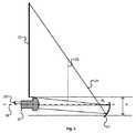
それらプロジェクタの体積を減少させるように、プロジェクタ1は、図1に分解して示しているように、凸状双曲面ミラーを備え、そのプロジェクタは、
− イメージングソース13と、
− イメージングソース13により生成されたイメージングビームが当たる対物レンズ10と、
− 画像を拡大する一方、ビームを折り返す凸状非球面ミラー11と、
− 折り返しミラー15と、
− リアプロジェクションスクリーン12と、
を有する。In order to reduce the volume of these projectors, the
An
An
A convex aspherical mirror 11 that magnifies the image while folding back the beam;
A
A
Have
対物レンズは凸状非球面ミラー11の方に結像ビーム14を透過し、その凸状非球面ミラー11自体は折り返しミラー15の方に反射ビームを透過し、その折り返しミラー15はスクリーン12の方にビームを反射する(図1を調べることが容易にするように、ビーム14はミラー15により折り返されないように示されている)。ミラー11、スクリーン12からみて、ビームがミラー11の後に位置している瞳孔領域Aからもたらされるようになっている。そのようなプロジェクタについては、欧州特許第1203977号明細書に詳細に記載されている。 The objective lens transmits the
図1のリアプロジェクタは、スクリーンの下に比較的大きい高さH、典型的には、30cmより大きい高さを有するという短所を有する。この高さは、実際には、対物レンズを収容し、対物レンズ10に入射するイメージングビームを用いずにスクリーン12に現画像を生成するために必要である。
本発明の目的は、上記の先行技術の短所を緩和することである。 The object of the present invention is to alleviate the disadvantages of the prior art described above.
特に、本発明の目的は、フロントプロジェクタの場合に、リアプロジェクションスクリーンの下の高さ(又は、“顎”と呼ばれる)又はプロジェクション距離(ここでは、プロジェクタがスクリーンの上に位置付けられている場合の、プロジェクタの最も高いレベルとスクリーンの最も高いレベルとの間の距離である)を減少させる一方、尚も小さい顎を保つことである。 In particular, the object of the present invention is, in the case of a front projector, the height below the rear projection screen (or called “jaw”) or the projection distance (here the projector is positioned above the screen). The distance between the highest level of the projector and the highest level of the screen), while still keeping the chin small.
このために、本発明においては、イメージングビームを生成するようにデザインされた対物レンズ及びイメージングソースを有するプロジェクションシステムであって、第1画像はイメージングビームの光軸に対して軸外にあり、そのシステムは、イメージングビームの経路中の第1画像の後に位置付けられ、第1画像からの投影面内に第2画像を構築する凹状ミラーを有することが注目に値する、プロジェクションシステムを提供する。To this end, in the present invention, a projection system having an objective lens and an imaging source designed to generate an imaging beam, the first image being off-axis with respect to the optical axis of the imaging beam, The system provides a projection system that is notable for having a concave mirror positioned after the first image in the path of the imaging beam and constructing the second image in aprojection plane from the first image.
好適には、凹状ミラーは非球面ミラーである。 Preferably, the concave mirror is an aspherical mirror.
特定の一特徴にしたがって、そのシステムは、対物レンズと凹状ミラーとの間に少なくとも第1平面状折り返しミラーを有する。 According to one particular feature, the system comprises at least a first planar folding mirror between the objective lens and the concave mirror.
有利であることに、対物レンズ系は、
− ダイアフラム、
− 第1レンズ群、及び
− 第2レンズ群
を有し、第2レンズ群は、イメージングビームの経路中のダイアフラムの後に位置付けられ、ダイアフラムより第1画像の方に近い。Advantageously, the objective lens system is
-Diaphragm,
A first lens group and a second lens group, the second lens group being positioned after the diaphragm in the path of the imaging beam and closer to the first image than the diaphragm.
好適な特徴にしたがって、第2レンズ群と第1レンズ群の射出瞳との間の距離は、第1レンズ群とイメージングソースとの間の距離の少なくとも3倍である。 According to a preferred feature, the distance between the second lens group and the exit pupil of the first lens group is at least three times the distance between the first lens group and the imaging source.
有利な特徴にしたがって、第2レンズ群は少なくとも1つのメニスカス型レンズを有する。 According to an advantageous feature, the second lens group comprises at least one meniscus lens.
特定の一特徴にしたがって、第2レンズ群は、第1レンズ群と第1折り返しミラーとの間に位置付けられている。 According to a particular feature, the second lens group is positioned between the first lens group and the first folding mirror.
他の特徴にしたがって、第2レンズ群は、第1折り返しミラーと凹状ミラーとの間に位置付けられている。 According to another feature, the second lens group is positioned between the first folding mirror and the concave mirror.
有利であることに、平面状折り返しミラーを有しないシステムの具現化においては、イメージングビームの光軸は投影面に対して垂直であり、イメージングビームが凹状ミラーに当たるときに、垂直である。Advantageously, in an implementation of a system that does not have a planar folding mirror, the optical axis of the imaging beam is perpendicular to theprojection plane and perpendicular when the imaging beam strikes the concave mirror.
好適には、そのシステムは、投影面においてリアプロジェクションスクリーンを有する。Preferably, the system has a rear projection screen at theprojection plane.
有利であることに、そのシステムは、凹状ミラーとリアプロジェクションスクリーンとの間のイメージングビームの経路に位置付けられた少なくとも第2折り返しミラーを更に有する。 Advantageously, the system further comprises at least a second folding mirror positioned in the path of the imaging beam between the concave mirror and the rear projection screen.
他の有利な特徴にしたがって、そのシステムは、投影面においてフロントプロジェクションのための手段を有する。According to another advantageous feature, the system comprises means for front projection at theprojection plane.
有利であることに、対物レンズ系は3つのレンズを有し、中央に位置しているレンズは外側の2つのレンズに対して逆のパワーを有する。それ故、フロント群は、例えば、発散レンズの側にある2つの収束レンズ又は収束レンズの側にある2つの発散レンズを有する。 Advantageously, the objective lens system has three lenses, and the centrally located lens has opposite power to the outer two lenses. Therefore, the front group has, for example, two converging lenses on the diverging lens side or two diverging lenses on the converging lens side.
好適には、そのシステムは、寄生光線を吸収する黒色領域と、凹状ミラーの後のイメージングビームの経路中に位置付けられている透明領域とを有するマスクを有する。 Preferably, the system comprises a mask having black areas that absorb parasitic rays and transparent areas that are positioned in the path of the imaging beam after the concave mirror.
特定の特徴にしたがって、透明領域はマスクにおいてフルである又はカットアウトに対応している。 According to certain features, the transparent area is full in the mask or corresponds to a cutout.
好適な特徴にしたがって、透明領域は、対物レンズ系及び凹状ミラーを有するシステムの射出瞳の近くに位置付けられている。 According to a preferred feature, the transparent region is located near the exit pupil of a system having an objective lens system and a concave mirror.
本発明については、添付図面を参照しながら、以下の詳述を読むときに、更に明確に理解でき、他の特徴及び有利点が明らかになるであろう。 The invention will be more clearly understood and other features and advantages will become apparent when the following detailed description is read with reference to the accompanying drawings.
本発明の一般的な原理は、それ故、リアプロジェクタにおける凹状折り返しミラーの使用に基づき、それにより、スクリーンの下の高さを減少することが可能になる。 The general principle of the present invention is therefore based on the use of a concave folding mirror in the rear projector, which makes it possible to reduce the height under the screen.
図2は、分解形式で、凹状非球面ミラーを有するリアプロジェクタであって、
− イメージングソース23(典型的には、照射ビームが当たるイメージャである)と、
− イメージングソース23により生成されるイメージングビームが当たる対物レンズ系20と、
− 折り返しミラー25と、
− リアプロジェクションスクリーン22と、
を有する、リアプロジェクタを示している。FIG. 2 is an exploded view of a rear projector having a concave aspheric mirror,
An imaging source 23 (typically an imager hit by the irradiation beam);
An
A
A
2 shows a rear projector having
イメージャは、例えば、Texas Instruments(登録商標)社製のDMD(“Digital Micromirrors Device”)、透過性LCD(Liquid Crystal Display)又はLCOS(Liquid Crystal on Silicon)である。 The imager is, for example, DMD (“Digital Micromirrors Device”), transmissive LCD (Liquid Crystal Display) or LCOS (Liquid Crystal on Silicon) manufactured by Texas Instruments (registered trademark).
対物レンズ系20は、凹状非球面ミラー21の方にイメージングビーム24を伝送し、その凹状非球面ミラー21自体は折り返しミラー25に反射ビームを伝送し、その折り返しミラー25は、スクリーン22が位置付けられている(図2が調べるのに容易であるように、ビーム24はミラー25により折り返されていないように示されている)投影面の方にそのビームを反射する。プロジェクタの光学部品は光軸26を有し、生成された光ビーム24はこの光軸26に対して軸外にある(それ故、イメージャである)。ミラー11は、スクリーン12からみて、ビームが瞳孔領域からもたらされるようにみえ、イメージングビームの経路24においてミラー21とスクリーン22との間に位置付けられている瞳PFに対応している。The
凹状非球面ミラー21は軸対称(回転)形状を有し、その凹状非球面ミラー21の反射面は次の非球面の式で与えられ、
Z(r)=(r2/R)/(1+√(1−(1+c)(r/R)2)+a1r+a2r2+a3r3+a4r4+a5r5+a6r6+・・・
ここで、
− rは光軸から所定点までの距離を表し、ミラー21の光軸は対物レンズ系の光軸に位置付けられていて、
− Zはその光軸に対して垂直な面からこの点までの距離を表し、
− 係数cは円錐であり、
− パラメータa1,a2,...,aiは指数1,2,...,iそれぞれの非球面係数である。The concave
Z (r) = (r2 / R) / (1 + √ (1− (1 + c) (r / R)2 ) + a1 r + a2 r2 + a3 r3 + a4 r4 + a5 r5 + a6 r6 + ...
here,
-R represents the distance from the optical axis to the predetermined point, the optical axis of the
-Z represents the distance from the plane perpendicular to the optical axis to this point;
The coefficient c is a cone;
The parameters a1 , a2 ,. . . , Ai are
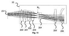
図11はかなり詳細に対物レンズ系20を示している。 FIG. 11 shows the
対物レンズ系は、レンズ201乃至203のリア群と、レンズ204乃至206のフロント群とを有する。 The objective lens system has a rear group of
イメージングビームの経路における対物レンズ系20の最後のレンズ206は、好適には、非球面メニスカスレンズであり、その非球面メニスカスレンズの形状は凹状ミラー21のパラメータに適合している。その形状は、それ故、上記のような非球面の式により好適に与えられる。 The
例示として、特定の一実施形態においては、凹状ミラー21の半径Rは60であり、パラメータc及びa1乃至a8のそれぞれは、次のようであり、−1.59311mm、0、0、−8.94x10⁻⁶、0、1.64x10⁻⁹、−9.74x10⁻¹³、−7.84x10⁻¹⁴及び2.31x10⁻¹⁶である。メニスカス206の第1面(イメージャ側)の半径Rは44.94711mmであり、パラメータc及びa1乃至a8はそれぞれ、次の値であって、0、0、0、−3.1x10⁻⁴、2.88x10⁻⁵、1.96x10⁻⁶、7.14x10⁻⁸、4.15x10⁻¹⁰及び−4.30x10⁻¹⁰を有する。メニスカス206の第2面(イメージャ側)の半径Rは29.49554mmであり、パラメータc及びa1乃至a8はそれぞれ、次の値であって、0、0、0、−2.7x10⁻⁴、9.97x10⁻⁶、6.34x10⁻⁷、−1.41x10⁻⁷、8.98x10⁻⁹及び−1.78x10⁻¹⁰を有する。By way of example, in one particular embodiment, the radius R of the
有利であることに、本発明にしたがって、フロントレンズ群は3つのレンズを有し、外側の位置に位置付けられている2つのレンズは中央に位置付けられているレンズに対して逆のパワーを有する。それ故、そのフロントレンズ群は、プロジェクトされた画像が平面状であるように、中間画像の曲率を生成することに寄与する一方、複数の弱いレンズを有する。このことは、そのフロントレンズ群の製造を容易にし、そのコストを削減するようにする。 Advantageously, according to the present invention, the front lens group has three lenses and the two lenses positioned in the outer position have opposite powers relative to the lens positioned in the center. Therefore, the front lens group has a plurality of weak lenses while contributing to generating the curvature of the intermediate image so that the projected image is planar. This facilitates the manufacture of the front lens group and reduces its cost.
それ故、図11に示すフロントレンズ群は、正パワーレンズ205(収束レンズ)の周りに2つの負パワーレンズ204及び106(発散レンズ)を有する。 Therefore, the front lens group shown in FIG. 11 has two
本発明の代替の実施形態にしたがって、対物レンズ系のフロントレンズ群は、負レンズの周りに2つの正(収束)レンズを有する。そのようなフロントレンズ群を有し、対物レンズ系20を置き換えることができる対物レンズ系130を図22に示す。 According to an alternative embodiment of the invention, the front lens group of the objective lens system has two positive (convergent) lenses around a negative lens. An
対物レンズ系130は、レンズ131乃至138のリア群とレンズ139乃至140のフロント群とを有し、それらのレンズ群は、対物レンズ系の射出瞳PEのどちらか一方の側に位置付けられている。
例示として、対物レンズ系130の特徴について、下記の表にまとめている(光線、厚さ及び直径はmmで表され、レンズ132乃至141の材料はOHARA(登録商標)社製の製品の参照番号に対応している。 As an example, the characteristics of the

図3a及び3bは、図2に模式的に示すようなリアプロジェクタ3の側面図及び平面図である。 3a and 3b are a side view and a plan view of the rear projector 3 as schematically shown in FIG.
リアプロジェクタ3の深さを減少するように、折り返しミラー30は、対物レンズ系20と凹状ミラー21との間に挿入されている。破線及び実線のそれぞれは、折り返されていない及び折り返されているビーム24を伴う要素を示している。ミラー30は鉛直(即ち、スクリーン22に対して平行)であり、ミラー21の前のビーム24の光軸は水平である。リアプロジェクタ3のイメージャ23の長手側は水平(長手側が水平である鉛直プロジェクションスクリーンについて)である。 The
対物レンズ系20は、その長手側に沿って位置付けられ、好適には、スクリーン22に平行な軸を有する、その長手側に沿って位置付けられた水平面内で好適に折り返され、それにより、リアプロジェクタ3の深さを減少することを可能にしている。ミラー30がスクリーンの垂直方向と成す角度αは、対物レンズ系20の光軸がスクリーン22と成す角度に依存する。対物レンズ系20がスクリーンに対して平行であるとき、角度αは45°に等しい。対物レンズ系20とミラー30との間の距離は、ビームが対物レンズ系20に当たらないようになっている。 The
一般に、折り返されていないプロジェクションシステムの複数の要素の光軸の全ては、鉛直であるとみなされる投影面に対して垂直である。それらの光軸は、それ故、水平である(凹状折り返しミラーによる折り返しを除いて、折り返されていない形式で示されているシステムについて)。In general, all of the optical axes of the elements of the projection system that are not folded are perpendicular to theprojection plane that is considered vertical. Their optical axes are therefore horizontal (for systems shown in an unfolded form, except for folding by a concave folding mirror).
プロジェクタ3においては、対物レンズ系20のリール軸は水平に保たれ、スクリーン22は鉛直である。プロジェクタ3は、比較的小さい“顎”、それ故、比較的小さいhの値を有する。 In the projector 3, the reel axis of the
しかしながら、照射部品が更に容易に収容されること(光照射コア、ランプケース、イメージャ23に取り付けられている電子カードの傾斜)を可能にする代替の実施形態においては、対物レンズ系のリール軸は傾けられている。このことは、プロジェクションシステムの一要素の軸は折り返しミラーにより折り返された後に非水平になることが可能であるためである。例えば、大きいミラーが傾けられている場合、後続する要素の全て、特に凹状ミラーはまた、その角度の2倍だけ傾けられる。 However, in an alternative embodiment that allows the illumination component to be more easily accommodated (light illumination core, lamp case, tilt of the electronic card attached to the imager 23), the reel axis of the objective lens system is Tilted. This is because the axis of one element of the projection system can be non-horizontal after being folded by the folding mirror. For example, if a large mirror is tilted, all subsequent elements, especially the concave mirror, are also tilted by twice that angle.
それ故、図4は、折り返しミラー40及び42を有する本発明の代替の実施形態にしたがったリアプロジェクタ4を示している。リアプロジェクタ4は、リアプロジェクタ3の構成要素に類似する要素を有し、それら(特に、イメージングソース23、対物レンズ系20、凹状ミラー21、折り返しミラー25及びスクリーン22)は同じ参照番号を有する。 Therefore, FIG. 4 shows a rear projector 4 according to an alternative embodiment of the present invention having folding mirrors 40 and 42. The rear projector 4 has elements that are similar to the components of the rear projector 3, and in particular they (imaging
2つの折り返しミラー40及び42は対物レンズ系20とミラー21との間に位置付けられている。リアプロジェクタ4の対物レンズ系20の軸は、折り返されるときに、水平ではない。対物レンズ系20からもたらされるイメージングビームは、先ず、ミラー42に当たり、そのミラー42は光軸に対して45°傾けられていて、スクリーン4に対して垂直である。そのビームは、それ故、スクリーン4に対して平行な方向に反射され、そのビームの光軸はスクリーン4に対して垂直な面内にある。次に、ミラー42により反射されたビームは、スクリーン4に対して垂直な法線及び光軸に対して45°傾けられているミラー40に当たる。そのビームは、それ故、凹状ミラー21に当たるように、スクリーン4に対して垂直な方向に反射される。 The two folding mirrors 40 and 42 are positioned between the
本発明の他の代替の実施形態においては、リアプロジェクタ4の対物レンズ系20の軸は、折り返されるときに水平ではなく、リアプロジェクタ4は、スクリーン21に対して略垂直な、好適には、垂直な方向にビームを送るように、対物レンズ系と凹状ミラー21との間に位置付けられている1つ又はそれ以上の折り返しミラーを有する。 In another alternative embodiment of the invention, the axis of the
本発明の他の代替の実施形態にしたがって、イメージングビームの経路において第1画像の後に位置付けられた凹状ミラーに当たるイメージングビームの軸は水平ではない。凹状ミラーの形状は、その場合、プロジェクションスクリーンに対応する投影面内に第2画像を構築するように演算される。According to another alternative embodiment of the invention, the axis of the imaging beam that hits the concave mirror positioned after the first image in the path of the imaging beam is not horizontal. The shape of the concave mirror is then calculated to build the second image in theprojection plane corresponding to the projection screen.
リアプロジェクタ4のイメージャ23の長手側は鉛直方向にある(水平な長手側を有する鉛直プロジェクションスクリーン22について)。 The longitudinal side of the
リアプロジェクタ4は、それがミラー21からの戻りビーム41を横断しないように、対物レンズ系20の複数のレンズのサイズの制限が予め回避されている。リアプロジェクタ4の構成においては、対物レンズ系はビーム41の下にあるため、大きいレンズを用いることがまた、可能である(フィールドを容易に分離することができる)。 In the rear projector 4, restriction of the size of the plurality of lenses of the
好適には、リアプロジェクタ4のスクリーンの下の高さh′はそのスクリーンの高さの(略)5分の1に等しい。更に正確には、高さh′は、5で除されたスクリーンの高さに等しいか又はそれより小さい。それはまた、対物レンズ系20又は凹状ミラー21の拡大縮小に、そして照射システム(ランプのリフレクタの大きさ)に依存する。それ故、50インチのスクリーン及びDMD HD3を有するプロジェクタについて、高さh′は、例えば、20cmより小さく、典型的には、12cmに等しい。 Preferably, the height h 'below the screen of the rear projector 4 is equal to (approximately) one fifth of the screen height. More precisely, the height h ′ is less than or equal to the height of the screen divided by 5. It also depends on the scaling of the
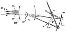
図5は、リアプロジェクタ3又は4により形成された複数の画像を示している(イメージングビームは折り返されないで示されている)。 FIG. 5 shows a plurality of images formed by the rear projector 3 or 4 (the imaging beam is shown without being folded).
光線242はイメージングビーム24の中央の構成を表し、光線240及び241が2つの極端光線である。
対物レンズ系20の射出瞳PEは、ビーム24の経路におけるミラーの前に位置付けられた画像IEを形成する。対物レンズ系20は、拡大率Mを有する画像IEを形成するように、イメージャ23において形成される対象物の画像を拡大する。対物レンズ系20に関連する拡大率Mは、好適には、1乃至10の範囲内にあり、更に好適には、5乃至9の範囲内にある。The exit pupil PE of the
ミラー21は、出射瞳PEを、イメージングビームの複数の光線が比較的小さい領域においてクロスオーバーする瞳PFに関連付ける。ミラー21の形状は、スクリーン22が位置付けられている投影面において投影された画像IEに対応する画像IMを生成するように演算されている。凹状ミラー21は、拡大率M′を有する画像IMを形成するように、画像IEを拡大する。凹状ミラー21に関連する拡大率M′は、好適には、対物レンズ系20に関連する拡大率Mより大きい。
前記イメージングビームの経路における第1画像の後に位置付けられた凹状ミラー21の使用は、光線241に対応するイメージングビームの下部が比較的高く(図1における対応する構成に対して)、それ故、凹状ミラーとスクリーンとの間のビームの伝播を乱すことなく、スクリーンに近い光学要素が容易に収容さあれることを可能にする。 The use of the
代替の実施形態にしたがって、凹状ミラー21に関連する拡大率M′は10より大きい。 According to an alternative embodiment, the magnification factor M ′ associated with the
凹状ミラー21は、好適には、光軸の下に位置付けられている。好適には、凹状ミラー21の前のシステムの光軸は水平方向にあり、スクリーン22の底部に近い。 The
図6は、リアプロジェクタ3の光学特性を示している。更に正確には、イメージングシステム23は、例示として示されている2つの点A及びBを有する第1画像を生成する。それらの2つの点A及びBからの発散はそれぞれ、2つのビーム62及び61であり、それらのビームは、少なくとも1つのレンズ200及び射出瞳PE201を有する対物レンズ系を透過した後に形成され、2つの点A′及びB′は対物レンズ系20により生成される画像IEに属している。FIG. 6 shows the optical characteristics of the rear projector 3. More precisely, the
ビーム62及び61はそれぞれ、ミラー21における非離散的領域A′′及びB′′において反射され、瞳PFに対応する領域に、ミラー21を介して瞳PEの画像を収束する。瞳PFはミラー21に比較的近く、瞳PEはミラー21から尚一層遠いことに留意する必要がある。典型的には、凹状ミラーの頂点から射出瞳孔領域までの距離は25mm乃至60mmの範囲内にある。好適には、凹状ミラー21から射出瞳までの距離はできるだけ大きい必要がある。Each
図7は、本発明の代替の実施形態にしたがったリアプロジェクタ80の一部を模式的に及び折り返さないで示している。 FIG. 7 schematically and partially shows a portion of a
リアプロジェクタ80は、プロジェクタ3及び4の構成要素に類似する構成要素(特に、構成要素22、23、25及び30)を有する。それらの構成要素は同じ参照番号を有するが、更なる説明はされていない。 The
リアプロジェクタ80は、ダイアフラムDと、少なくとも1つのレンズを有する第1レンズ群74と、少なくとも1つのレンズを有する第2レンズ群70とを有する。第2レンズ群は、イメージングビームの経路におけるダイアフラムDの後に位置付けられ、そのダイアフラムDより画像IEに近い。好適には、第2レンズ群70と第1レンズ群74の射出瞳PE′との間の距離d1は、第1レンズ群74とイメージングソース23との間の距離の少なくとも3倍である。The
射出瞳PE′は第1レンズ群74により形成されるダイアフラムDの画像に対応する。第2レンズ群70は、実質的に無限遠におけるプロジェクタ80の対物レンズ系の射出瞳PEを位置決めすることを可能にする。それ故、第2レンズ群70はイメージングビームの光線(例えば、点A及びBに対応する光線72及び71)を反射し、ミラー21を置き替える、その形状がまた類似している、凹状ミラー73の大きさを減少させることを可能にする。The exit pupil PE ′ corresponds to the image of the diaphragm D formed by the
第2レンズ群70はまた、上記の他の実施形態にしたがったミラー21が役割を果たす光学補正を適用する。特に、非点収差及び特定の光学歪みを低減することが可能である。また、そのことはビームの開口(開口2.8)を増加させる。ミラー73は、それ故、画像IEを拡大し、投影面において平面的画像を得ることを本質的に可能にする曲率を有する。The
凹状非球面ミラー73は、その表面が次式で与えられる形状を有し、
Z(r)=(r2/R)/(1+√(1−(1+c)(r/R)2)+a1r+a2r2+a3r3+a4r4+a5r5+a6r6+・・・
ここで、
− rは光軸から所定点までの距離を表し、ミラー74の光軸は対物レンズ系の光軸に位置付けられていて、
− Zはその光軸に対して垂直な面からこの点までの距離を表し、
− 係数cは円錐であり、
− パラメータaiは指数iの非球面係数である。The concave
Z (r) = (r2 / R) / (1 + √ (1− (1 + c) (r / R)2 ) + a1 r + a2 r2 + a3 r3 + a4 r4 + a5 r5 + a6 r6 + ...
here,
-R represents the distance from the optical axis to the predetermined point, the optical axis of the
-Z represents the distance from the plane perpendicular to the optical axis to this point;
The coefficient c is a cone;
The parameter ai is the aspheric coefficient of index i.
第2レンズ群70は、1つ又はそれ以上のレンズを有し、例えば、1つ又はそれ以上のメニスカスレンズ(容易に製造することができる複数のメニスカスレンズを有するレンズ群)を有する。好適には、第2レンズ群70は、凹状ミラー73のパラメータに適合された光学特性を有する。その構成要素は、上記の非球面式に従う形状を有する。 The
例示として、特定の一実施形態においては、−56.202mmに等しく、パラメータc及びa1乃至a8のそれぞれは、次のようであり、−3.32197、0、0、−1.06x10⁻⁵、0、−2.20x10⁻⁹、6.68x10⁻¹¹、−1.06x10⁻¹²及び5.91x10⁻¹⁶である。By way of example, in one particular embodiment, equal to −56.202 mm, the parameters c and a1 to a8 are as follows: −3.332197, 0, 0, −1.06 × 10− 5 , 0, -2.20 × 10⁻⁹ , 6.68 × 10⁻¹¹ , −1.06 × 10⁻¹² and 5.91 × 10⁻¹⁶ .
また、例示として、レンズ群70はメニスカスを有するとみなされる。レンズ群70のメニスカスの第1面(イメージャ側)の半径Rは無限大であるとみなされ、パラメータc及びa1乃至a8のそれぞれは、次のようであり、0、0、−0.00811、7.60x10⁻⁵、−6.43x10⁻⁶、1.57x10⁻⁷、−1.53x10⁻⁹、0及び0である。レンズ群70のメニスカスの第2面(イメージャ側)の半径Rは無限大であるとみなされ、パラメータc及びa1乃至a8のそれぞれは、次のようであり、0、0、−0.01058、−1.77x10⁻⁵、−2.88x10⁻⁶、8.41x10−87、−9.96x10⁻¹⁰、0及び0である。Further, as an example, the
第1レンズ群74は、イメージングビームの経路においてダイアフラムの前に位置付けられている1つ又はそれ以上のレンズのリア群を有する。代替の実施形態にしたがって、それはまた、イメージングビームの経路においてダイアフラムの後に位置付けられている1つ又はそれ以上のレンズのフロント群を有する。 The
更に、画像IEはミラー73の前に形成され、ミラー73は、出射瞳PEを、イメージングビームの複数の光線が比較的小さい領域において横断する瞳PFと関連付ける。ミラー73の形状は、スクリーン22がある投影面における画像IEに対応する画像IMを生成するように演算されている。Furthermore, the image IE is formed in front of the
図8は、リアプロジェクタ80の模式的な平面図である。 FIG. 8 is a schematic plan view of the
プロジェクタ80において、第2レンズ群70は、折り返しミラー30と第1レンズ群74との間に位置付けられている。それ故、イメージャ23は、第2レンズ群70に第1レンズ群74を介してイメージングビーム81を伝送する。第2レンズ群70は、凹状ミラー73の方に折り返しミラー30により反射されるイメージングビーム82にイメージングビーム81を補正する。 In the
イメージングビーム81の光軸はプロジェクションスクリーンに投影される画像の底部に対して平行及び水平である(リアプロジェクタ3の実施形態におけるように)。代替の実施形態においては、イメージングビームの光軸は、図4に示すように、リアプロジェクタ4の対物レンズ系からもたらされるイメージングビームの軸のように、傾けられていて、ミラー30は、リアプロジェクタ4のミラー40により置き替えられている。 The optical axis of the
図9は、リアプロジェクタ80の代替の実施形態に対応するリアプロジェクタ80の模式的な平面図である。 FIG. 9 is a schematic plan view of a
リアプロジェクタ90はリアプロジェクタ80の構成要素に類似する構成要素を有し、ミラー73、第1レンズ群74及び第2レンズ群70はそれぞれ、凹状ミラー92、少なくとも1つのレンズを有する第1レンズ群95及び少なくとも1つのレンズを有する第2レンズ群91により置き替えられている。それらの類似する構成要素は同じ参照番号を有し、それらについてはここでは更に説明しない
リアプロジェクタ90の対物レンズ系は、それ故、ダイアフラムD、第1レンズ群95及び第2レンズ群91を有する。第2レンズ群91は、イメージングビームの経路におけるダイアフラムDの後に位置付けられ、ダイアフラムDより画像IEに近い。好適には、第2レンズ群91(距離d′′1及びd′′′1の和に対応)と第1レンズ群74の射出瞳PE′との間の光学距離は、第1レンズ群95とイメージングソース23との間の距離d2の少なくとも3倍である。The
凹状ミラー92及び少なくとも1つのレンズを有する第2レンズ群91は、ミラー73及び第1レンズ群74のそれぞれと同じ機能を備えている。ミラー92の形状及び第2レンズ群91の光学特性は、それらの2つの構成要素に対して略調和がとれている。 The
プロジェクタ90においては、第2レンズ群91は、折り返しミラー30と凹状ミラー92との間に位置付けられている。それ故、イメージャ23は、イメージングビーム93が第1レンズ群95を透過するようにし、そのビーム93は、折り返しミラー30により第2レンズ群91の方に反射される。第2レンズ群91は、凹状ミラー73の方に透過されるイメージングビーム92にイメージングビームを補正する。 In the
イメージングビーム93の光軸は、プロジェクションスクリーンの方に投影される画像の底部に対して平行且つ水平である(リアプロジェクタ3の実施形態におけるように)。代替の実施形態においては、平面状又は凹状折り返しミラーの一により反射される前のイメージングビーム93の光軸は投影面に対して傾けられている。The optical axis of the
リアプロジェクタ90の代替の実施形態にしたがって、平面状折り返しミラー30は、リアプロジェクタ4のミラー40及び42に類似する2つのミラーで置き替えられ、それらの2つのミラーは、リアプロジェクタの大きさを減少させるように、第1レンズ群95と第2レンズ群91との間に位置付けられている。そのような実施形態は、ミラー73に類似する凹状ミラー92と互換性があり、第2レンズ群91はレンズ群70に類似する単一のメニスカスを有し、それらの構成要素の正確な特性については、例示として上で説明している。 In accordance with an alternative embodiment of the
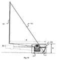
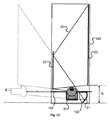
図10は、本発明の代替の実施形態にしたがったフロントビデオプロジェクタ100を示している。 FIG. 10 shows a
プロジェクタ100は、プロジェクションスクリーン22及び折り返しミラー25を除いて、プロジェクタ3の光学構成要素を有する。 The
更に正確には、プロジェクタ100は、プロジェクタ3の構成要素20、23、30及び21に類似する構成要素を有し、それらの構成要素は同じ参照番号を有し、それらについては更に説明しない。プロジェクタ100の凹状ミラー21は、折り返されていないシステムの光軸に対して垂直な投影面内にあるスクリーン101の方にイメージングビーム102を伝送し、凹状ミラー21は、対物レンズ系20とミラー21との間に位置付けられている第1画像から投影面において第2画像を構築する。投影面はプロジェクタ100に対して非常に近いことが可能であり、投影面から凹状ミラー21の光中心までの距離は、好適には、1m以下であり、更に好適には、50cm以下である。More precisely, the
更に、顎h(下方から上方に投影される画像を前提として、プロジェクタ100の最も低い点からスクリーン101に投影される画像を分離する距離)は比較的小さく、それは、好適には、投影された画像の高さの5分の1より小さい。 Furthermore, the jaw h (the distance separating the image projected on the
更に、上記のように、本発明の複数の実施形態にしたがったリアプロジェクタは、フロントプロジェクタに適合されることが可能であり、当業者は、リアプロジェクションスクリーンをフロントプロジェクションスクリーンで置き替え、イメージングビームの経路において凹状ミラーの後に位置付けられた折り返しミラーを有効に省くことができる。 Furthermore, as described above, a rear projector according to embodiments of the present invention can be adapted to a front projector, and one skilled in the art can replace a rear projection screen with a front projection screen to obtain an imaging beam. In this path, the folding mirror positioned after the concave mirror can be effectively omitted.
本発明の他の特徴にしたがって、マスクが小さい瞳孔領域の近くに位置付けられ、その領域は、イメージングビームの経路において対物レンズ系とスクリーンとの間に位置付けられている。そのようなマスクは、そのシステムの射出瞳が本物であるときに、用いられることが可能である。そのマスクは、特に、寄生光線を制限する、削除することさえ可能であり、及び/又は、ダストが対物レンズ系、凹状ミラー及び対物レンズ系に近い光学要素に堆積することを回避する。上記のように、そのような瞳PFは、特に、プロジェクタが投影面において画像を構築するために収束ミラーを用いるときに得られる。In accordance with another feature of the invention, the mask is positioned near a small pupil area, which is positioned between the objective lens system and the screen in the path of the imaging beam. Such a mask can be used when the exit pupil of the system is real. The mask can in particular limit or even eliminate parasitic rays and / or avoid dust being deposited on the objective lens system, concave mirrors and optical elements close to the objective lens system. As noted above, such a pupil PF is particularly projector are obtained when using a converging mirror to construct an image ina projection plane.
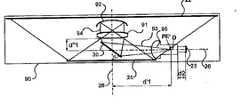
図12及び13は、リアプロジェクタ120を側面図及び平面図のそれぞれで示している。リアプロジェクタ120は、同じ参照番号を有するが、ここではそれらについて更に説明しないリアプロジェクタ3の要素全てと、マスク103とを有する。 12 and 13 show the
有利であることに、マスク103は、プロジェクションビーム24が透過することが可能である透明領域104を有するガラス又はプラスチックのシートである。マスク103の厚さは、できるだけ薄い、好適には、2mm以下、更に好適には、1mmに等しいか又はそれ以下であるように選択される。 Advantageously, the
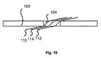
図19に示すように、ビーム24の光線113乃至115は透明領域104を透過し、マスク103により反射される。透明領域104の外側においては、マスク103は黒色であり、寄生光線を吸収する。黒色非球面領域は、マスクの一方側又は両側においてバルクを染められた又は処理されたマスクの領域に対応する。好適には、透明領域には、当業者にとって既知である技術を用いる反射防止処理が行われる。マスク103は、好適には、プロジェクタボックスの境界に関して拡大され、それ故、対物レンズ系、凹状ミラー及び対応するイメージャからダストを絶たれ、及び/又は、それらの要素から又は外側からもたらされる寄生光線を削除(又は低減)する。例示としてのマスクの透明領域の境界は、マスクの表面に対して垂直な壁を有する。マスク103の有利な代替の実施形態にしたがって、マスクの透明領域の境界は、イメージングビームの経路において収束するように、傾いた壁を有する。 As shown in FIG. 19, the light rays 113 to 115 of the beam 24 pass through the
代替の実施形態にしたがって、マスクの透明領域は、傾斜角を減少させるように、それ故、透明領域にイメージングビームの何れの反射を低減するように、ビームをイメージングする領域の軸に対して傾けられる。 According to an alternative embodiment, the transparent area of the mask is tilted with respect to the axis of the area where the beam is imaged so as to reduce the tilt angle and therefore reduce any reflection of the imaging beam to the transparent area. It is done.
それ故、図21は、マスク103の変形であるマスク121を示している。マスク121は、透明領域127を取り囲んでいる黒色上部面125及び黒色下部面を有する。それらの面125及び126は、面125及び126に近い(好適には、距離が2mmかそれ以下)か又は接しているまさに極端光線113及び115を有するように、マスク121に対して垂直な方向に沿って相殺される。それ故、例示としての実施形態にしたがって、面125及び126は相殺されず、イメージングビームの経路において収束するように、マスク121の透明領域の境界は傾けられた壁を有する。マスクの代替の実施形態にしたがって、透明領域の壁はマスクの面に対して垂直である。他の代替としての実施形態にしたがって、マスクの1つの面のみが黒色である。この面は、好適には、イメージングビームの入射面側にある。 Therefore, FIG. 21 shows a
マスク103及び116の代替の実施形態にしたがって、透明領域はガラス又はプラスチックから成り、黒色領域は何れの他の材料から成る。 According to alternative embodiments of the
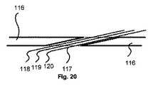
図20は、カットアウト透明領域117を有する黒色マスク116(マスク103の変形)を示している。ビーム24の光線113及び115は、回折又は吸収されることなく、透明領域117を透過する。 FIG. 20 shows a black mask 116 (a deformation of the mask 103) having a cut-out transparent region 117. FIG. The light rays 113 and 115 of the beam 24 pass through the transparent region 117 without being diffracted or absorbed.
マスク103、121及び116の透明領域は、好適には、ビーム24の大きさに対して調節され、対物レンズ系と投影面との間にある瞳孔領域(又は、対物レンズ系及び凹状ミラーを有するシステムの瞳PF)の近く(典型的には、対物レンズ系及び凹状ミラーを有するシステムの射出瞳に対応する瞳孔領域PFからの距離5mm又はそれ以下)に位置付けられる。The transparent areas of the
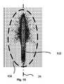
マスクを製造することを容易にするように、透明領域は単純な幾何学的形状を有する。それ故、図15は、マスクが光軸26上にあるとき、瞳孔領域PF105のインプリントを囲む透明領域104を示している。瞳孔領域105(又はビーム24)のインプリントは、軸26に対して対称的であり、この軸に沿って幾らか長くされている。それ故、例示として、透明領域は、軸106上に中心を置く楕円形であり、その楕円形の長軸(軸106上に置かれた)及び短軸は約50mm及び30mmの長さをそれぞれ有する。The transparent area has a simple geometric shape so as to facilitate the manufacture of the mask. Therefore, FIG. 15 shows the
図16に示すマスクの変形にしたがって、透明領域107は、瞳孔領域105のインプリントをより精細に示している。それ故、その領域107の一端部(例えば、幅が10mmである)は他端部(例えば、幅が20mmである)より狭い。 According to the deformation of the mask shown in FIG. 16, the
図17は、瞳孔領域PF近くの軸26の周り5mmに位置付けられた透明マスク領域110を示している。ビーム24のインプリント109は、図14及び15に示されているインプリントより大きく、矢印の先端のような形状を有する。透明領域110はまた、インプリント109のまさにその形状に追従している。Figure 17 illustrates a
図18は、瞳孔領域PF近くの軸26の下2mmにある透明マスク領域110を示している。ビーム24のインプリント112は、図14及び15に示されているインプリントより大きく、一端部においてフレア状の形状を有する。透明領域112はまた、インプリント109のまさにその形状に追従している。Figure 18 illustrates a
図14は、フロントプロジェクタ106の側面図である。プロジェクタ106は、それらの要素は同じ参照番号を有し、更にそれらについて説明しないが、プロジェクタ100の要素全てと、マスク105とを有する。マスク105は、照射ビームを透過するようにする透明領域であって、そのマスクが、複数の実施形態にしたがって、透明領域104、107、110及び112それぞれに類似している、透明領域と、寄生光線を吸収し、プロジェクタ106の光学要素を囲むボックスに関して拡大されている黒色領域であって、マスク103の黒色領域に類似する、黒色領域とを有する。 FIG. 14 is a side view of the
図12及び21に示しているマスクは、好適には、平面状である。他の実施形態にしたがって、黒色領域と、適切な場合には、フル透明領域は形状が変化し、それらは対物レンズ系を含む光学要素の全て又は一部を囲むように、及び、黒色領域は、投影されるビームの明度を低減させないように、照射ビームを横断しない。 The masks shown in FIGS. 12 and 21 are preferably planar. According to other embodiments, the black areas and, where appropriate, the fully transparent areas change shape, so that they surround all or part of the optical element including the objective lens system, and the black areas are Do not traverse the illumination beam so as not to reduce the brightness of the projected beam.
透明領域がフル領域であるとき、そのビームの一部は透明部分により反射されることが可能である。代替の実施形態にしたがって、このようにして、得られた寄生光線は、例えば、マスクに対して略垂直である壁により削除され、有用なプロジェクションビームの経路の外側のそれらの寄生光線の経路における透明領域の背後に置かれる。 When the transparent area is a full area, a part of the beam can be reflected by the transparent area. According to an alternative embodiment, thus obtained parasitic rays are eliminated, for example by walls that are substantially perpendicular to the mask, in those parasitic ray paths outside the useful projection beam path. Placed behind the transparent area.
プロジェクタの代替の実施形態にしたがって、イメージャは、上記の場合に対して、中心が外れていて、それにより、高品質の投影画像を得ることが可能である。このように、また、マスクを位置決めする自由度が大きく、及び/又は、マスクの形状における自由度が大きい。 According to an alternative embodiment of the projector, the imager is off-center with respect to the above case, so that a high quality projection image can be obtained. As described above, the degree of freedom for positioning the mask is large and / or the degree of freedom in the shape of the mask is large.
勿論、本発明は、上記の実施形態に限定されるものではない。 Of course, the present invention is not limited to the above embodiment.
特に、本発明は、何れの種類のプロジェクタに対して、フロントプロジェクタ、リアプロジェクタを問わず、適用できる。 In particular, the present invention can be applied to any type of projector, regardless of whether it is a front projector or a rear projector.
当業者はまた、例えば、特定の基準にしたがって非点収差及び光学歪み補正を適合させ、プロジェクションシステムの複数の光学系間にそれらを割り当てるように、凹状ミラーの前に位置付けられた第1画像からの投影面において第2画像を構築する凹状折り返しミラー及び対物レンズ系を規定することができる。The person skilled in the art can also, for example, adapt the astigmatism and optical distortion correction according to specific criteria and from the first image positioned in front of the concave mirror so as to assign them between the optical systems of the projection system. A concave folding mirror and an objective lens system for constructing the second image on theprojection plane can be defined.
更に、当業者は、所望のプロジェクションシステムに特定の空間的制約にしたがって、イメージングビームの折り返しを適合させることができるであろう。
[付記]
(フロントプロジェクタ又はリアプロジェクタのための折り返しプロジェクションシステム)
付記(1):
イメージングビームを生成するようにデザインされた対物レンズ系及びイメージングソースを有し、前記対物レンズ系の後に位置付けられた第1画像を構築するプロジェクションシステムであって、前記第1画像は前記対物レンズ系の光軸に対して軸外にある、プロジェクションシステムであり:
前記イメージングビームの経路における前記第1画像の後に位置付けられ、前記第1画像から投影面において第2画像を構築する凹状ミラーを有し、前記凹状ミラーは、前記対物レンズ系の前記光軸において位置付けられた光軸を有する;
ことを特徴とする、プロジェクションシステム。
付記(2):
付記(1)に記載のプロジェクションシステムであって、前記凹状ミラーは非球面ミラーであることを特徴とする、プロジェクションシステム。
付記(3):
付記(1)又は(2)に記載のプロジェクションシステムであって、前記対物レンズ系と前記凹状ミラーとの間に少なくとも第1平面状折り返しミラーを有することを特徴とする、プロジェクションシステム。
付記(4):
付記(1)乃至(3)のいずれか一つに記載のプロジェクションシステムであって、前記対物レンズ系は:
ダイアフラム;
第1レンズ群;及び
第2レンズ群;
を有する、プロジェクションシステムであり、
前記第2レンズ群は、前記イメージングビームの前記経路における前記ダイアフラムの後に位置付けられ、前記ダイアフラムより前記第1画像に近い;
ことを特徴とする、プロジェクションシステム。
付記(5):
付記(4)に記載のプロジェクションシステムであって、前記第2レンズ群と前記第1レンズ群の射出瞳との間の距離は前記第1レンズ群と前記イメージングソースとの間の距離の少なくとも3倍であることを特徴とする、プロジェクションシステム。
付記(6):
付記(4)又は(5)に記載のプロジェクションシステムであって、前記第2レンズ群は少なくとも1つのメニスカス型レンズを有することを特徴とする、プロジェクションシステム。
付記(7):
付記(4)乃至(6)のいずれか一つに記載の、付記(3)によるプロジェクションシステムであって、前記第2レンズ群は前記第1レンズ群と前記第1折り返しミラーとの間に位置付けられていることを特徴とする、プロジェクションシステム。
付記(8):
付記(4)乃至(7)のいずれか一つに記載の、付記(3)によるプロジェクションシステムであって、前記第2レンズ群は前記第1折り返しミラーと前記凹状ミラーとの間に位置付けられていることを特徴とする、プロジェクションシステム。
付記(9):
付記(1)乃至(8)のいずれか一つに記載のプロジェクションシステムであって、折り返しミラーを有しないプロジェクションシステムの具現化であって、前記イメージングビームの前記光軸は前記の投影面に対して垂直であり、前記イメージングビームが前記凹状ミラーに当たるときに鉛直であることを特徴とする、プロジェクションシステム。
付記(10):
付記(1)乃至(9)のいずれか一つに記載のプロジェクションシステムであって、前記の投影面においてリアプロジェクションスクリーンを有することを特徴とする、プロジェクションシステム。
付記(11):
付記(10)に記載のプロジェクションシステムであって、前記凹状ミラーと前記リアプロジェクションスクリーンとの間に前記イメージングビームの前記経路において位置付けられた少なくとも第2平面状折り返しミラーを更に有することを特徴とする、プロジェクションシステム。
付記(12):
付記(1)乃至(9)のいずれか一つに記載のプロジェクションシステムであって、前記の投影面においてフロントプロジェクションのための手段を有することを特徴とする、プロジェクションシステム。
付記(13):
付記(1)乃至(12)のいずれか一つに記載のプロジェクションシステムであって、前記対物レンズ系は3つのレンズを有するフロント群を有し、前記3つのレンズは、中央に位置付けられたレンズは外側の2つのレンズに対して逆パワーを有することを特徴とする、プロジェクションシステム。
付記(14):
付記(1)乃至(13)のいずれか一つに記載のプロジェクションシステムであって、寄生光線を吸収する黒色領域と、前記凹状ミラーの後に前記イメージングビームの前記経路に位置付けられた透明領域とを有することを特徴とする、プロジェクションシステム。
付記(15):
付記(14)に記載のプロジェクションシステムであって、前記透明領域はフル領域であることを特徴とする、プロジェクションシステム。
付記(16):
付記(14)に記載のプロジェクションシステムであって、前記マスクは前記透明領域を形成するカットオフを有することを特徴とする、プロジェクションシステム。
付記(17):
付記(14)乃至(16)のいずれか一つに記載のプロジェクションシステムであって、前記透明領域は、前記対物レンズ系及び前記凹状ミラーを有する前記プロジェクションシステムの射出瞳の近くに位置付けられていることを特徴とする、プロジェクションシステム。Furthermore, those skilled in the art will be able to adapt the folding of the imaging beam according to the spatial constraints specific to the desired projection system.
[Appendix]
(Folded projection system for front projector or rear projector)
Appendix (1):
A projection system having an objective lens system and an imaging source designed to generate an imaging beam and constructing a first image positioned after the objective lens system, wherein the first image is the objective lens system Projection system off-axis to the optical axis of:
A concave mirror positioned after the first image in the path of the imaging beam and constructing a second image in theprojection plane from the first image, the concave mirror positioned at the optical axis of the objective lens system Having a defined optical axis;
A projection system characterized by this.
Appendix (2):
The projection system according to appendix (1), wherein the concave mirror is an aspherical mirror.
Appendix (3):
The projection system according to appendix (1) or (2), wherein the projection system includes at least a first planar folding mirror between the objective lens system and the concave mirror.
Appendix (4):
The projection system according to any one of appendices (1) to (3), wherein the objective lens system is:
Diaphragm;
A first lens group; and a second lens group;
A projection system comprising:
The second lens group is positioned after the diaphragm in the path of the imaging beam and is closer to the first image than the diaphragm;
A projection system characterized by this.
Appendix (5):
The projection system according to appendix (4), wherein a distance between the second lens group and an exit pupil of the first lens group is at least 3 of a distance between the first lens group and the imaging source. Projection system characterized by being doubled.
Appendix (6):
The projection system according to appendix (4) or (5), wherein the second lens group includes at least one meniscus lens.
Appendix (7):
The projection system according to appendix (3) according to any one of appendices (4) to (6), wherein the second lens group is positioned between the first lens group and the first folding mirror. Projection system, characterized by
Appendix (8):
The projection system according to appendix (3) according to any one of appendices (4) to (7), wherein the second lens group is positioned between the first folding mirror and the concave mirror. A projection system characterized by
Appendix (9):
The projection system according to any one of appendices (1) to (8), wherein the projection system does not include a folding mirror, and the optical axis of the imaging beam is relative to theprojection plane. A projection system, wherein the projection system is vertical when the imaging beam hits the concave mirror.
Appendix (10):
The projection system according to any one of appendices (1) to (9), wherein the projection system includes a rear projection screen on theprojection surface.
Appendix (11):
The projection system according to appendix (10), further comprising at least a second planar folding mirror positioned in the path of the imaging beam between the concave mirror and the rear projection screen. , Projection system.
Appendix (12):
The projection system according to any one of appendices (1) to (9), wherein the projection system includes means for front projection on theprojection plane.
Appendix (13):
The projection system according to any one of appendices (1) to (12), wherein the objective lens system includes a front group having three lenses, and the three lenses are positioned in the center. Has a reverse power with respect to the outer two lenses.
Appendix (14):
The projection system according to any one of appendices (1) to (13), comprising: a black region that absorbs parasitic light; and a transparent region that is positioned in the path of the imaging beam after the concave mirror. A projection system comprising: a projection system;
Appendix (15):
The projection system according to appendix (14), wherein the transparent area is a full area.
Appendix (16):
The projection system according to appendix (14), wherein the mask has a cut-off for forming the transparent region.
Appendix (17):
The projection system according to any one of appendices (14) to (16), wherein the transparent region is positioned near an exit pupil of the projection system having the objective lens system and the concave mirror. A projection system characterized by this.
Claims (12)
Translated fromJapaneseソースイメージを発生させるイメージングソースと、
光軸を有し、対物レンズ系を通じて上記のソースイメージの第一のイメージを構成する上記対物レンズ系と、
上記第一のイメージの後に配置され、上記第一のイメージから投影面に第二のイメージを構成する凹状のミラーと、
上記凹状のミラーの後の上記イメージングビームの経路上に配置された、寄生の光線を吸収する黒色のゾーンと、透明なゾーンとを有するマスクと、
上記のイメージングビームの経路中の少なくとも一つの折り返しミラーと、
を有するプロジェクションシステムであって、
上記第一のイメージは、上記対物レンズ系の光軸に対して軸外であり、
上記凹状のミラーの光軸は、上記対物レンズ系の光軸上にあり、
上記対物レンズ系及び上記凹状のミラーを含む系である光学系の射出瞳は、上記凹状のミラー及び上記投影面の間にあり、
上記凹状のミラーの光学的な中心の、上記投影面からの距離は、1m未満であり、
上記のマスクの上記透明なゾーンは、上記の射出瞳から5mm以下の距離に配置された、
プロジェクションシステム。In the path of the imaging beam,
An imaging source for generating a source image;
The objective lens system having an optical axis and constituting a first image of the source image through the objective lens system;
A concave mirror disposed after the first image and constituting a second image from the first image to a projection plane;
A mask disposed on the path of the imaging beam after the concave mirror and having a black zone for absorbing parasitic rays and a transparent zone;
At least one folding mirror in the path of the imaging beam;
A projection system comprising:
The first image is off-axis with respect to the optical axis of the objective lens system,
The optical axis of the concave mirror is on the optical axis of the objective lens system,
The exit pupil of the optical system which is a system including the objective lens system and the concave mirror is between the concave mirror and the projection plane,
The distance from the projection plane of the optical center of the concave mirror is less than 1 m;
The transparent zone of the mask is disposed at a distance of 5 mm or less from the exit pupil,
Projection system.
ことを特徴とする、請求項1に記載のプロジェクションシステム。The projection system according to claim 1, wherein the concave mirror is an aspherical mirror.
ダイアフラム、
第一のレンズ群、及び
第二のレンズ群を有し、
上記第二のレンズ群が上記のイメージングビームの経路中の上記絞りの後に位置決めされたものであり、上記ダイアフラムよりも上記第一のイメージにより近い、請求項1ないし3いずれか一項に記載のプロジェクションシステム。The objective lens system is
Diaphragm,
Having a first lens group and a second lens group,
4. The device according to claim 1, wherein the second lens group is positioned after the diaphragm in the path of the imaging beam, and is closer to the first image than the diaphragm. 5. Projection system.
上記の第二のレンズ群は、上記の第一のレンズ群及び上記第一の平面折り返しミラーの間に位置決めされたものであること
を特徴とする、請求項4に記載のプロジェクションシステム。The at least one folding mirror also includes at least one first planar folding mirror between the objective lens system and the concave mirror;
The second lens group described above, and characterized in that positioned between the first lens group and the upperSymbol first planefolding mirror above, projection system according to claim 4.
上記第二のレンズ群は、上記第一の折り返しミラー及び上記凹状のミラーの間に配置されること
を特徴とする、請求項4に記載のプロジェクションシステム。The system also includes at least one first plane folding mirror between the objective lens system and the concave mirror;
The projection system according to claim 4, wherein the second lens group is disposed between the first folding mirror and the concave mirror.
Applications Claiming Priority (3)
| Application Number | Priority Date | Filing Date | Title |
|---|---|---|---|
| FR0412904AFR2878968B1 (en) | 2004-12-03 | 2004-12-03 | PROJECTION SYSTEM |
| FR0412904 | 2004-12-03 | ||
| PCT/EP2005/056318WO2006058884A1 (en) | 2004-12-03 | 2005-11-29 | Folded projection system for a front or rear projector |
Publications (2)
| Publication Number | Publication Date |
|---|---|
| JP2008522229A JP2008522229A (en) | 2008-06-26 |
| JP5363732B2true JP5363732B2 (en) | 2013-12-11 |
Family
ID=34951019
Family Applications (1)
| Application Number | Title | Priority Date | Filing Date |
|---|---|---|---|
| JP2007543843AExpired - Fee RelatedJP5363732B2 (en) | 2004-12-03 | 2005-11-29 | Projection system |
Country Status (7)
| Country | Link |
|---|---|
| US (1) | US20080192208A1 (en) |
| EP (1) | EP1817631B1 (en) |
| JP (1) | JP5363732B2 (en) |
| KR (1) | KR101179565B1 (en) |
| CN (1) | CN100573311C (en) |
| FR (1) | FR2878968B1 (en) |
| WO (1) | WO2006058884A1 (en) |
Families Citing this family (33)
| Publication number | Priority date | Publication date | Assignee | Title |
|---|---|---|---|---|
| JP2008090200A (en)* | 2006-10-05 | 2008-04-17 | Sony Corp | Zoom lens and projection image display device |
| JP4668159B2 (en)* | 2006-11-06 | 2011-04-13 | ソニー株式会社 | Projection optical system and projection-type image display device |
| JP5181637B2 (en)* | 2006-12-04 | 2013-04-10 | 株式会社リコー | Image projection device |
| US7922340B2 (en)* | 2007-02-14 | 2011-04-12 | Konica Minolta Opto, Inc. | Projection optical system with enlargement at a varying magnification |
| JP5180689B2 (en)* | 2007-08-07 | 2013-04-10 | 三洋電機株式会社 | Projection display device |
| US8128238B2 (en)* | 2007-09-07 | 2012-03-06 | Ricoh Company, Ltd. | Projection optical system and image displaying apparatus |
| JP4829196B2 (en)* | 2007-09-28 | 2011-12-07 | 株式会社リコー | Projection optical device |
| JP5166847B2 (en)* | 2007-12-14 | 2013-03-21 | 三洋電機株式会社 | Projection display device |
| JP2009236965A (en)* | 2008-03-25 | 2009-10-15 | Sanyo Electric Co Ltd | Projection type video display |
| JP4827873B2 (en)* | 2008-03-27 | 2011-11-30 | 三洋電機株式会社 | Projection display device |
| JP4827872B2 (en)* | 2008-03-27 | 2011-11-30 | 三洋電機株式会社 | Projection display device |
| JP4827874B2 (en)* | 2008-03-27 | 2011-11-30 | 三洋電機株式会社 | Projection display device |
| WO2009119808A1 (en)* | 2008-03-27 | 2009-10-01 | 三洋電機株式会社 | Projection video display device |
| JP2009244371A (en)* | 2008-03-28 | 2009-10-22 | Sanyo Electric Co Ltd | Projection type image display device |
| JP2009244379A (en)* | 2008-03-28 | 2009-10-22 | Sanyo Electric Co Ltd | Projection type image display |
| JP2009244415A (en)* | 2008-03-28 | 2009-10-22 | Sanyo Electric Co Ltd | Projection type image display |
| JP2009244378A (en)* | 2008-03-28 | 2009-10-22 | Sanyo Electric Co Ltd | Projection type image display |
| JP2009244372A (en)* | 2008-03-28 | 2009-10-22 | Sanyo Electric Co Ltd | Projection type image display |
| JP4557051B2 (en) | 2008-06-17 | 2010-10-06 | セイコーエプソン株式会社 | projector |
| JP5181899B2 (en)* | 2008-07-25 | 2013-04-10 | 株式会社リコー | Image reading apparatus and image forming apparatus |
| JP5312891B2 (en)* | 2008-10-03 | 2013-10-09 | 三洋電機株式会社 | Refractive optical system and projection-type image display device |
| US8434878B2 (en) | 2008-12-26 | 2013-05-07 | Seiko Epson Corporation | Proximity projector with a transmissive cover with modified reflectance properties |
| US8054556B2 (en)* | 2009-03-13 | 2011-11-08 | Young Optics Inc. | Lens |
| FR2955673B1 (en) | 2010-01-22 | 2012-07-27 | Optinvent | REASONABLY WIDE ANGLE DISTANCE PROJECTION DEVICE WITH ZOOM AND FOCUS |
| KR20120051831A (en)* | 2010-11-15 | 2012-05-23 | 삼성전자주식회사 | Projector and driving method thereof |
| TWI454741B (en)* | 2011-05-23 | 2014-10-01 | Qisda Corp | Projection apparatus |
| JP5686256B2 (en) | 2011-08-30 | 2015-03-18 | 株式会社リコー | Projector device |
| JP5825047B2 (en) | 2011-10-28 | 2015-12-02 | 株式会社リコー | Image display device |
| CN104050905B (en)* | 2013-03-11 | 2017-10-10 | 徐峻峰 | One kind projection display body |
| JP5963057B2 (en) | 2013-07-26 | 2016-08-03 | 株式会社リコー | Projection optical system and image projection apparatus |
| JP5975012B2 (en)* | 2013-11-19 | 2016-08-23 | 株式会社リコー | Image projection device |
| JP2019144414A (en)* | 2018-02-21 | 2019-08-29 | 矢崎総業株式会社 | Display device for vehicle |
| JP7357515B2 (en)* | 2019-11-18 | 2023-10-06 | リコーインダストリアルソリューションズ株式会社 | image projection device |
Family Cites Families (14)
| Publication number | Priority date | Publication date | Assignee | Title |
|---|---|---|---|---|
| JP2786796B2 (en)* | 1993-06-23 | 1998-08-13 | シャープ株式会社 | projector |
| JP3541576B2 (en)* | 1995-10-25 | 2004-07-14 | ミノルタ株式会社 | Imaging optics |
| JPH1073884A (en)* | 1996-08-30 | 1998-03-17 | Minolta Co Ltd | Overhead projector device |
| JP2000338448A (en)* | 1999-05-31 | 2000-12-08 | Minolta Co Ltd | Projection type picture display device |
| DE60040181D1 (en)* | 1999-07-14 | 2008-10-16 | Nec Display Solutions Ltd | See-through protection system with obliquely incident light beam |
| US6485145B1 (en)* | 1999-12-21 | 2002-11-26 | Scram Technologies, Inc. | Optical system for display panel |
| JP4453154B2 (en)* | 2000-03-17 | 2010-04-21 | コニカミノルタオプト株式会社 | Oblique projection optical system and rear projection optical system |
| JP3727543B2 (en)* | 2000-05-10 | 2005-12-14 | 三菱電機株式会社 | Image display device |
| JP2002057963A (en)* | 2000-08-10 | 2002-02-22 | Canon Inc | Display device |
| JP2002341452A (en)* | 2001-05-14 | 2002-11-27 | Olympus Optical Co Ltd | Image projecting device, multiple image projecting device and screen |
| JP4223936B2 (en)* | 2003-02-06 | 2009-02-12 | 株式会社リコー | Projection optical system, enlargement projection optical system, enlargement projection apparatus, and image projection apparatus |
| JP4086686B2 (en)* | 2003-03-18 | 2008-05-14 | キヤノン株式会社 | Projection optical system, projection-type image display device and image display system |
| JP2005173230A (en)* | 2003-12-11 | 2005-06-30 | Canon Inc | Optical system and image projection apparatus |
| BRPI0509037A (en)* | 2004-03-30 | 2007-08-07 | Thomson Licensing | projection module and projector built into it |
- 2004
- 2004-12-03FRFR0412904Apatent/FR2878968B1/ennot_activeExpired - Fee Related
- 2005
- 2005-11-29CNCNB2005800412246Apatent/CN100573311C/ennot_activeExpired - Fee Related
- 2005-11-29KRKR1020077012083Apatent/KR101179565B1/ennot_activeExpired - Fee Related
- 2005-11-29EPEP05813347Apatent/EP1817631B1/ennot_activeNot-in-force
- 2005-11-29JPJP2007543843Apatent/JP5363732B2/ennot_activeExpired - Fee Related
- 2005-11-29USUS11/791,266patent/US20080192208A1/ennot_activeAbandoned
- 2005-11-29WOPCT/EP2005/056318patent/WO2006058884A1/enactiveApplication Filing
Also Published As
| Publication number | Publication date |
|---|---|
| WO2006058884A1 (en) | 2006-06-08 |
| CN100573311C (en) | 2009-12-23 |
| CN101069126A (en) | 2007-11-07 |
| EP1817631B1 (en) | 2011-09-07 |
| FR2878968B1 (en) | 2008-02-22 |
| EP1817631A1 (en) | 2007-08-15 |
| KR20070085514A (en) | 2007-08-27 |
| US20080192208A1 (en) | 2008-08-14 |
| JP2008522229A (en) | 2008-06-26 |
| FR2878968A1 (en) | 2006-06-09 |
| KR101179565B1 (en) | 2012-09-05 |
Similar Documents
| Publication | Publication Date | Title |
|---|---|---|
| JP5363732B2 (en) | Projection system | |
| CN101794063B (en) | Projection type image display apparatus | |
| JP5114828B2 (en) | Projection optical unit | |
| US8254039B2 (en) | Variable magnification optical system and projector | |
| JP5042818B2 (en) | Projection module and projector using projection module | |
| JP5825047B2 (en) | Image display device | |
| US7789516B2 (en) | Projection type image display device | |
| CN101089724A (en) | Projection type image display device | |
| JP3904597B2 (en) | Projection display | |
| JP2007316674A (en) | Projection optical system, enlargement projection optical system, enlargement projection apparatus, and image projection apparatus | |
| JP6221266B2 (en) | Projection optical system and image display device | |
| JP4933083B2 (en) | Projection-type image display device and projection optical unit thereof | |
| JP2013061604A (en) | Projection optical system and image projection apparatus | |
| JP2000187274A (en) | Rear projection type LCD project equipment | |
| JP4859667B2 (en) | Projection objective lens or projection or rear projection device | |
| CN100578350C (en) | projection display device | |
| JP2014044377A (en) | Projector and projection optical system | |
| JP2005024716A (en) | Imaging optical system, optical system, optical apparatus, imaging apparatus, image reading apparatus, and projection-type image display apparatus | |
| JP2000089227A (en) | Projection display device | |
| JP6679854B2 (en) | Projection device and image display device | |
| JP2011007990A (en) | Projector | |
| JP6249005B2 (en) | Projection optical system and image display device | |
| JP4767696B2 (en) | Projection-type image display device | |
| JP2006139055A (en) | Projection display | |
| JP6341367B2 (en) | Projection device and projection system |
Legal Events
| Date | Code | Title | Description |
|---|---|---|---|
| A621 | Written request for application examination | Free format text:JAPANESE INTERMEDIATE CODE: A621 Effective date:20081104 | |
| A977 | Report on retrieval | Free format text:JAPANESE INTERMEDIATE CODE: A971007 Effective date:20110322 | |
| A131 | Notification of reasons for refusal | Free format text:JAPANESE INTERMEDIATE CODE: A131 Effective date:20110405 | |
| A521 | Request for written amendment filed | Free format text:JAPANESE INTERMEDIATE CODE: A523 Effective date:20110705 | |
| A131 | Notification of reasons for refusal | Free format text:JAPANESE INTERMEDIATE CODE: A131 Effective date:20120724 | |
| A521 | Request for written amendment filed | Free format text:JAPANESE INTERMEDIATE CODE: A523 Effective date:20121024 | |
| A131 | Notification of reasons for refusal | Free format text:JAPANESE INTERMEDIATE CODE: A131 Effective date:20130312 | |
| A521 | Request for written amendment filed | Free format text:JAPANESE INTERMEDIATE CODE: A523 Effective date:20130612 | |
| TRDD | Decision of grant or rejection written | ||
| A01 | Written decision to grant a patent or to grant a registration (utility model) | Free format text:JAPANESE INTERMEDIATE CODE: A01 Effective date:20130827 | |
| A61 | First payment of annual fees (during grant procedure) | Free format text:JAPANESE INTERMEDIATE CODE: A61 Effective date:20130906 | |
| R150 | Certificate of patent or registration of utility model | Ref document number:5363732 Country of ref document:JP Free format text:JAPANESE INTERMEDIATE CODE: R150 Free format text:JAPANESE INTERMEDIATE CODE: R150 | |
| R250 | Receipt of annual fees | Free format text:JAPANESE INTERMEDIATE CODE: R250 | |
| R250 | Receipt of annual fees | Free format text:JAPANESE INTERMEDIATE CODE: R250 | |
| S111 | Request for change of ownership or part of ownership | Free format text:JAPANESE INTERMEDIATE CODE: R313113 | |
| S531 | Written request for registration of change of domicile | Free format text:JAPANESE INTERMEDIATE CODE: R313531 | |
| R350 | Written notification of registration of transfer | Free format text:JAPANESE INTERMEDIATE CODE: R350 | |
| R250 | Receipt of annual fees | Free format text:JAPANESE INTERMEDIATE CODE: R250 | |
| LAPS | Cancellation because of no payment of annual fees |