JP5359586B2 - Golf club and method for adjusting characteristics thereof - Google Patents
Golf club and method for adjusting characteristics thereofDownload PDFInfo
- Publication number
- JP5359586B2 JP5359586B2JP2009142316AJP2009142316AJP5359586B2JP 5359586 B2JP5359586 B2JP 5359586B2JP 2009142316 AJP2009142316 AJP 2009142316AJP 2009142316 AJP2009142316 AJP 2009142316AJP 5359586 B2JP5359586 B2JP 5359586B2
- Authority
- JP
- Japan
- Prior art keywords
- hosel
- shaft
- insertion hole
- shaft case
- golf club
- Prior art date
- Legal status (The legal status is an assumption and is not a legal conclusion. Google has not performed a legal analysis and makes no representation as to the accuracy of the status listed.)
- Expired - Fee Related
Links
Images


Classifications
- A—HUMAN NECESSITIES
- A63—SPORTS; GAMES; AMUSEMENTS
- A63B—APPARATUS FOR PHYSICAL TRAINING, GYMNASTICS, SWIMMING, CLIMBING, OR FENCING; BALL GAMES; TRAINING EQUIPMENT
- A63B53/00—Golf clubs
- A63B53/02—Joint structures between the head and the shaft
- A—HUMAN NECESSITIES
- A63—SPORTS; GAMES; AMUSEMENTS
- A63B—APPARATUS FOR PHYSICAL TRAINING, GYMNASTICS, SWIMMING, CLIMBING, OR FENCING; BALL GAMES; TRAINING EQUIPMENT
- A63B60/00—Details or accessories of golf clubs, bats, rackets or the like
- A63B60/02—Ballast means for adjusting the centre of mass
- A—HUMAN NECESSITIES
- A63—SPORTS; GAMES; AMUSEMENTS
- A63B—APPARATUS FOR PHYSICAL TRAINING, GYMNASTICS, SWIMMING, CLIMBING, OR FENCING; BALL GAMES; TRAINING EQUIPMENT
- A63B60/00—Details or accessories of golf clubs, bats, rackets or the like
- A63B60/54—Details or accessories of golf clubs, bats, rackets or the like with means for damping vibrations
- A—HUMAN NECESSITIES
- A63—SPORTS; GAMES; AMUSEMENTS
- A63B—APPARATUS FOR PHYSICAL TRAINING, GYMNASTICS, SWIMMING, CLIMBING, OR FENCING; BALL GAMES; TRAINING EQUIPMENT
- A63B53/00—Golf clubs
- A63B53/02—Joint structures between the head and the shaft
- A63B53/022—Joint structures between the head and the shaft allowing adjustable positioning of the head with respect to the shaft
- A63B53/023—Joint structures between the head and the shaft allowing adjustable positioning of the head with respect to the shaft adjustable angular orientation
Landscapes
- Health & Medical Sciences (AREA)
- General Health & Medical Sciences (AREA)
- Physical Education & Sports Medicine (AREA)
- Golf Clubs (AREA)
Description
Translated fromJapanese本発明は、ゴルフクラブに係り、特にライ角、スライス角、グース等の特性の調節を容易に行うことができるゴルフクラブに関する。また、本発明は、このゴルフクラブの特性調節方法に関する。The present invention relates to a golf club, particularly lie angle, aboutthe slice angle, Gorufukurablanking that can be easily performed adjustment of characteristics of the goose or the like. The present invention also relates to a method for adjusting the characteristics of the golf club.
ゴルフクラブは、シャフトの先端部にヘッドが取り付けられたものである。シャフトの基端側にグリップが装着されている。 A golf club has a head attached to the tip of a shaft. A grip is attached to the proximal end of the shaft.
従来の一般的なゴルフクラブヘッドにあっては、ヘッドに直にホゼル穴が設けられており、シャフトは該ホゼル穴に挿入され、接着剤によって固着されている。なお、この接着剤は、一般にエポキシ系接着剤が用いられている。シャフト交換に際しては、ホゼル部分を加熱してエポキシ樹脂硬化物よりなる組織を壊すことにより、シャフトを引き抜く。 In a conventional general golf club head, a hosel hole is provided directly in the head, and a shaft is inserted into the hosel hole and fixed by an adhesive. In general, an epoxy adhesive is used as the adhesive. When exchanging the shaft, the shaft is pulled out by heating the hosel part to break the structure made of the cured epoxy resin.
特開平11−178954には、ヘッド本体とホゼルとを別体とし、このホゼルをヘッド本体にねじによって固定したゴルフクラブヘッドが記載されている。この特開平11−178954では、ホゼルの下端側に板状のネック部を設け、このネック部をヘッド本体の挿着部に差し込み、ねじで固定している。このように板状のネック部をヘッド本体に固定することにより、ボールをヒットしたインパクト時にネック部にしなりを生じさせ、シャフトとホゼルとの結合部に生じる応力集中が緩和される。 Japanese Patent Application Laid-Open No. 11-178554 describes a golf club head in which a head body and a hosel are separately provided and the hosel is fixed to the head body with screws. In JP-A-11-178554, a plate-like neck portion is provided on the lower end side of the hosel, and this neck portion is inserted into an insertion portion of the head body and fixed with screws. By fixing the plate-like neck portion to the head main body in this way, the neck portion is bent at the time of impact when the ball is hit, and the stress concentration generated at the joint portion between the shaft and the hosel is alleviated.
上記特開平11−178954のゴルフクラブヘッドでは、ライ角やスライス角などは調節することができない。また、ヘッド本体とホゼルとの結合強度及び剛性が不足し、力強いインパクト感が得られない。また、ホゼル位置が過度に高くなる。 In the golf club head disclosed in JP-A-11-178554, the lie angle and slice angle cannot be adjusted. Further, the strength and rigidity of the connection between the head body and the hosel are insufficient, and a strong impact feeling cannot be obtained. Also, the hosel position becomes excessively high.
本発明は、上記従来の問題点を解消し、ライ角やスライス角、グース等の特性を調節することができるゴルフクラブと、その特性調節方法を提供することを目的とする。The present invention is to solve the above problems, an object of lie angle and slice angle,and Gorufukurablanking capable of modulating the properties of the Goose etc., to provide the characteristic adjustment method.
請求項1のゴルフクラブは、ゴルフクラブヘッドのシャフト挿入穴にシャフトの先端が挿入されて固着されてなるゴルフクラブにおいて、該ゴルフクラブヘッドは、ホゼル挿入穴を有したヘッド本体と、シャフトケース挿入穴を有し、該ホゼル挿入穴に着脱可能に装着されたホゼルと、前記シャフト挿入穴を有し、該シャフトケース挿入穴に着脱可能に装着されたシャフトケースと、を備えてなり、該ホゼルは、該ホゼル挿入穴の軸心周りの周方向位相を変更して装着可能であり、且つ、該シャフトケース挿入穴の位置及び角度の少なくとも一方が異なる別のホゼルと交換可能であり、前記シャフトの軸心が該ホゼル挿入穴の軸心に対し傾斜方向となっており、該ホゼル挿入穴の入口部の内周面に第1の雌螺子が設けられており、前記ホゼルに、外周面に第1の雄螺子を有した第1の螺子部材が回転自在にかつ軸心方向移動不能に外嵌しており、該第1の雄螺子を第1の雌螺子に螺着させることにより、前記ホゼルが前記ヘッド本体に固定されていることを特徴とするものである。GorufukuraBed according to
請求項2のゴルフクラブは、請求項1において、前記シャフトケース挿入穴の入口部の内周面に第2の雌螺子が設けられており、前記シャフトケースに、外周面に第2の雄螺子を有した第2の螺子部材が回転自在にかつ軸心方向移動不能に外嵌しており、該第2の雄螺子を第2の雌螺子に螺着させることにより、前記シャフトケースが前記ホゼルに固定されていることを特徴とするものである。A golf club according to asecond aspect is the golf club according to the first aspect, wherein a second female screw is provided on the inner peripheral surface of the entrance portion of the shaft case insertion hole, and the second male screw is provided on the outer peripheral surface of the shaft case. A second screw member having a shaft is externally fitted so as to be rotatable and immovable in the axial direction. The second male screw is screwed onto the second female screw, whereby the shaft case is moved to the hosel. isto shalland characterized in that it is fixed to.
請求項3のゴルフクラブは、ゴルフクラブヘッドのシャフト挿入穴にシャフトの先端が挿入されて固着されてなるゴルフクラブにおいて、該ゴルフクラブヘッドは、ホゼル挿入穴を有したヘッド本体と、シャフトケース挿入穴を有し、該ホゼル挿入穴に着脱可能に装着されたホゼルと、前記シャフト挿入穴を有し、該シャフトケース挿入穴に着脱可能に装着されたシャフトケースと、を備えてなり、該ホゼルは、該ホゼル挿入穴の軸心周りの周方向位相を変更して装着可能であり、且つ、該シャフトケース挿入穴の位置及び角度の少なくとも一方が異なる別のホゼルと交換可能であり、前記シャフトの軸心がホゼル挿入穴の軸心に対し傾斜方向となっており、該ホゼル挿入穴の入口部の内周面に第1の雌螺子が設けられており、前記シャフトケースに、外周面に第1の雄螺子を有した第1の螺子部材が回転自在にかつ軸心方向移動不能に外嵌しており、該第1の雄螺子を第1の雌螺子に螺着させることにより、前記ホゼルが前記ヘッド本体に固定されていることを特徴とするものである。4. The golf club according to
請求項4のゴルフクラブは、請求項3において、前記第1の螺子部材の入口部の内周面に第2の雌螺子が設けられており、前記シャフトケースに、外周面に第2の雄螺子を有した第2の螺子部材が回転自在にかつ軸心方向移動不能に外嵌しており、該第2の雄螺子を第2の雌螺子に螺着させることにより、前記シャフトケースが前記ホゼルに固定されていることを特徴とするものである。The golf club according to claim4, Oiteto claim3,and a second female screw is provided on the inner peripheral surface of the inlet portion of thefirst screw member, the shaft case, the second on the outer peripheral surface A second screw member having a male screw is externally fitted so as to be rotatable and non-movable in the axial direction, and the second male screw is screwed onto the second female screw, whereby the shaft case Is fixed to the hosel .
請求項5のゴルフクラブは、請求項1ないし4のいずれか1項において、該シャフトケースは、該シャフトケース挿入穴の軸心周りの周方向位相を変更して装着可能であり、且つ、別のシャフトケースと交換可能であることを特徴とするものである。A golf club according to afifth aspect is the golf club accordingto any one of the first to fourth aspects,wherein the shaftcase can be mounted by changing a circumferential phase around the axis of the shaft case insertion hole, and replaceable der Rukotoand the shaft case is characterized in.
請求項6のゴルフクラブは、請求項1ないし5のいずれか1項において、前記シャフトの軸心がシャフトケース挿入穴の軸心と同軸状となっていることを特徴とするものである。According to asixth aspect of the present invention, in the golf club accordingto any one of the first to fifth aspects, the shaft centerof the shaft is coaxial with the shaft center of theshaft case insertion hole .
請求項7のゴルフクラブは、請求項1ないし6のいずれか1項において、該ホゼルの下端側及びホゼル挿入穴の奥部が多角断面形状部となっており、両者が係合していることを特徴とするものである。The golf club according to claim7 is the golf club according to anyone of
請求項8のゴルフクラブは、請求項7において、前記ホゼルの下端側とホゼル挿入穴の奥部の内面との間に弾性体が介在していることを特徴とするものである。The golf club of
請求項9のゴルフクラブの特性調節方法は、請求項1ないし8のいずれか1項に記載のゴルフクラブの特性を調節する方法であって、前記ホゼルをホゼル挿入穴及びシャフトケースと分離し、該ホゼルをシャフトケース挿入穴の位置又は角度が異なる別のホゼルと交換し、その後、前記シャフトケースをシャフトケース挿入穴に固定すると共にホゼルをホゼル挿入穴に固定することを特徴とするものである。A method for adjusting characteristics of a golf club according to claim9 is a method for adjusting characteristics of a golf club according to anyone of
請求項10のゴルフクラブの特性調節方法は、請求項1ないし8のいずれか1項に記載のゴルフクラブのシャフトを新たなシャフトに交換して特性を調節する方法であって、予め新たなシャフトを新たなシャフトケースに固着して新たなシャフトケース・シャフト連結体を作成しておき、ゴルフクラブに取り付けられているシャフトケース・シャフト連結体をヘッドから取り外し、このヘッドに新たなシャフトケース・シャフト連結体を取り付けることを特徴とするものである。A method for adjusting characteristics of a golf club according to claim10 is a method for adjusting characteristics by exchanging the shaft of the golf club according to anyone of
本発明のゴルフクラブ及びそのヘッドにあっては、ヘッド本体にホゼルが着脱可能に装着され、このホゼルにシャフトケースが着脱可能に装着されており、ホゼルをヘッド本体のホゼル装着穴から抜き出すことができると共に、シャフトケースをホゼルのシャフトケース挿入穴から抜き出すことができる。そこで、このホゼルをライ角、スライス角又はグースの異なる別のホゼルに交換するか又はホゼルの周方向位相を変更し、このホゼルを介してシャフト付きシャフトケースを再びヘッド本体に装着する。 In the golf club and the head of the present invention, the hosel is detachably attached to the head body, and the shaft case is detachably attached to the hosel, and the hosel can be extracted from the hosel attachment hole of the head body. In addition, the shaft case can be extracted from the shaft case insertion hole of the hosel. Therefore, the hosel is replaced with another hosel having a different lie angle, slice angle, or goose, or the circumferential phase of the hosel is changed, and the shaft case with a shaft is mounted on the head body again through the hosel.
例えば、シャフトの軸心がホゼル挿入穴の軸心に対し斜め方向(例えば斜交方向)となっているホゼルに交換することにより、ヘッド本体に対するシャフトの取り付け方向が変更され、ライ角やスライス角が変更される。 For example, by changing to a hosel whose shaft center is oblique to the shaft center of the hosel insertion hole (for example, oblique direction), the shaft mounting direction relative to the head body is changed, and the lie angle or slice angle Is changed.
従って、全く同一のシャフト及び同一のヘッド本体からなるゴルフクラブにおいて、ライ角又はスライス角のみを調節することができる。 Therefore, in a golf club consisting of exactly the same shaft and the same head body, only the lie angle or slice angle can be adjusted.
また、シャフトケース挿入穴の軸心位置がホゼル挿入穴の軸心位置から平行移動状にずれているホゼルに交換することにより、全く同一のシャフト及び同一のヘッド本体からなるゴルフクラブにおいて、グースや、シャフトから重心までの距離(重心距離)を調節することができる。 Further, by replacing the hosel whose axis position of the shaft case insertion hole is displaced in parallel with the axis position of the hosel insertion hole, in the golf club consisting of the completely same shaft and the same head body, The distance from the shaft to the center of gravity (center of gravity distance) can be adjusted.
なお、本発明では、ホゼルを交換せずにシャフトケース付きシャフトを交換してシャフト交換することもできる。即ち、シャフトケースとして全く同型のシャフトケースを用意しておき、このシャフトケースに別特性のシャフトを固着してシャフトケース・シャフト連結体としておき、このシャフトケース・シャフト連結体をそれまでのヘッドシャフトケース・シャフト連結体と交換して当該ヘッドのホゼルに取り付けることにより、シャフトのみが異なったゴルフクラブを得ることができる。 In the present invention, the shaft can be replaced by replacing the shaft with the shaft case without replacing the hosel. That is, a shaft case of exactly the same type is prepared as a shaft case, and a shaft with a different characteristic is secured to the shaft case as a shaft case / shaft coupling body, and this shaft case / shaft coupling body is used as the head shaft up to that point. By replacing the case-shaft assembly and attaching it to the hosel of the head, a golf club having only a different shaft can be obtained.
このシャフト交換方法によれば、従来のように加熱によって接着剤の組織を壊してシャフトを取り外し、新たなシャフトを再度接着剤で取り付けるという面倒な手間及び時間を省くことができる。そのため、試打したばかりのゴルフクラブのヘッドからシャフトケース・シャフト連結体を取り外し、このヘッドに異なる特性の別のシャフトケース・シャフト連結体を取り付けて直ちに試打を行うことができるので、ゴルフショップ等でゴルファーが適切なゴルフクラブを見出すことが極めて容易となる。また、ヘッドの固体差を考慮することなくシャフトの評価を行うことができる。 According to this shaft exchanging method, it is possible to save the troublesome labor and time of breaking the adhesive structure by heating, removing the shaft, and reattaching the new shaft with the adhesive as in the prior art. Therefore, it is possible to remove the shaft case / shaft coupling body from the head of the golf club that has just been tried and attach another shaft case / shaft coupling body with different characteristics to this head, so that the test can be performed immediately. It becomes extremely easy for the golfer to find a suitable golf club. Further, the shaft can be evaluated without considering the difference between the individual heads.
近年、ゴルファーが自分の技量にあったゴルフクラブを探すために、コンピュータや高速カメラなどを使って、自分にマッチしたゴルフクラブを探すシステムが開発されてきている。このようなシステムは、ヘッドスピードや打ち出し角度などを基に個々の市販クラブをベースに打ち比べて探すようにしたシステムである。 In recent years, a system for searching for a golf club that matches a golf club using a computer or a high-speed camera has been developed in order for a golfer to search for a golf club suitable for his / her skill. Such a system is a system in which a search is made by comparing individual commercial clubs based on the head speed, launch angle, and the like.
これに対し、本発明のゴルフクラブによれば、同一のシャフトとヘッドとの位置関係のみを変更して重心距離やプログレッションを変更し、打ち出されたボールの飛球特性(打ち出し角やスピン)の違いを容易に実感したり、同じヘッドに対してシャフトのみを付け替えて、シャフトのみの違いを実感したりすることができる。また、その日のプレーヤーの調子に応じてシャフトを交換したり、シャフトは同一のまま、ライ角やスライス角、グースを調整するために、ヘッドに対するシャフトの取り付け方向を変更したりすることもできる。 On the other hand, according to the golf club of the present invention, only the positional relationship between the same shaft and the head is changed to change the center-of-gravity distance and progression, and the flying ball characteristics (launch angle and spin) of the launched ball are changed. You can easily feel the difference, or change only the shaft to the same head and feel the difference only in the shaft. Also, the shaft can be exchanged according to the player's condition of the day, or the shaft mounting direction can be changed to adjust the lie angle, slice angle, and goose while the shaft remains the same.
なお、ホゼルの下端側及びホゼル挿入穴の奥部を多角形断面形状としておくと、ホゼルの周方向の位置決め(位相決め)が行われる。また、ヘッドとホゼルとの間での回転が防止される。 In addition, if the lower end side of the hosel and the inner part of the hosel insertion hole have a polygonal cross-sectional shape, positioning (phase determination) in the circumferential direction of the hosel is performed. Further, rotation between the head and the hosel is prevented.
ホゼルの下端とホゼル挿入穴の奥部内面との間に弾性体を介在させると、ホゼル挿入穴とホゼルとの間の衝撃や振動が吸収される。 If an elastic body is interposed between the lower end of the hosel and the inner surface of the inner portion of the hosel insertion hole, the impact and vibration between the hosel insertion hole and the hosel are absorbed.
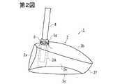
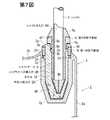
以下、図面を参照して実施の形態について説明する。第1図は実施の形態に係るゴルフクラブヘッドの正面図、第2図及び第3図は第1図の状態からホゼルを交換して再装着したゴルフクラブの側面図、第4図は第1図の状態からホゼルを交換して再装着したゴルフクラブの正面図である。第5図は第1図のV−V線断面図、第6図はホゼル、シャフトケース、螺子部材及びシャフト先端部の斜視図である。 Hereinafter, embodiments will be described with reference to the drawings. FIG. 1 is a front view of a golf club head according to an embodiment, FIGS. 2 and 3 are side views of a golf club in which a hosel is replaced and remounted from the state of FIG. 1, and FIG. It is a front view of the golf club which replaced the hosel from the state of a figure, and was mounted | worn again. FIG. 5 is a cross-sectional view taken along line VV of FIG. 1, and FIG. 6 is a perspective view of the hosel, shaft case, screw member, and shaft tip.
まず、ホゼル3を用いたヘッドについて、第1図、第5図及び第6図を参照して説明する。 First, a head using the
このゴルフクラブは、ヘッド1に着脱可能に装着されたホゼル3に対し、シャフト4付きのシャフトケース5を第2の螺子部材6を介して取り付けたものである。 In this golf club, a shaft case 5 with a shaft 4 is attached to a
このヘッド1は、ヘッド本体2と、このヘッド本体2に着脱可能に取り付けられたホゼル3とを有する。このヘッド1は中空のウッド型のものであり、フェース部2aと、クラウン部2bと、ソール部2cと、トウ部2dと、ヒール部2eと、バック部2fとを有する。 The
第5図の通り、クラウン部2bのフェース部2a側かつヒール部2e側に、ホゼル挿入穴2Hを有した円筒状のホゼル設置部2gが設けられている。このホゼル設置部2gは、上端が開放し、下端が閉じた円筒形であり、ホゼル3の差込方向に延在している。ホゼル挿入穴2Hの入口側の内周面に雌螺子2mが刻設されている。雌螺子2mより若干奥側に、縮径方向に段差面2sが設けられている。この段差面2sよりも奥側に引き続いて円筒面が形成されている。 As shown in FIG. 5, a cylindrical
ホゼル挿入穴2Hの該円筒面よりも奥側の内周面は、奥側ほど小径となる正四角錐形となっており、ホゼル3の軸心と斜交する4面の斜面2k(第5図)が設けられている。対向する1対の斜面2k同士の交差角度(挟角)は10〜30°特に15〜20°程度が好適である。 The inner peripheral surface on the back side of the cylindrical surface of the hosel insertion hole 2H is a regular quadrangular pyramid having a smaller diameter toward the back side, and four
このホゼル挿入穴2H内にホゼル3が上方から挿入され、第1の螺子部材9を雌螺子2mにねじ込むことによりホゼル3がホゼル設置部2gに固定される。 The
第5,6図に示す通り、ホゼル3は、上端から下端に向けて軸心線方向にシャフトケース挿入穴3Hが穿設された略円筒形である。 As shown in FIGS. 5 and 6, the
ホゼル3の下端側の外面は、下端ほど小径となる四角錐形(正確には切頭四角錐形)であり、4面の斜面3kが設けられている。斜面3kは、ホゼル3の軸心線を挟んで対称に設けられている。対向する1対の斜面3k,3k同士の交差角度は、ホゼル挿入穴2Hの最奥部の斜面2k,2kの交差角度と同一である。ホゼル3の斜面3kとホゼル挿入穴2Hの斜面2kとの間に弾性体8Aを介在させ、がたつきを防止している。 The outer surface on the lower end side of the
ホゼル3の下部の外周面は、この実施の形態では正四角錐形であるが、正三角錐形、正六角錐形、正八角錐形などの正多角錐形であってもよい。 The lower outer peripheral surface of the
シャフトケース挿入穴3Hの入口側すなわちホゼル3の上端側の内周面には雌螺子3aが設けられている。この実施の形態では、この雌螺子3aに後述の第2の螺子部材6がねじ込まれる。 A
この雌螺子3aに引き続いて、縮径方向に段差面3bが設けられ、この段差面3bよりも奥側に円筒面が形成されている。この円筒面よりも奥側の内面は、奥側ほど小径となる正四角錐形となっており、ホゼル3の軸心と斜交する4面の斜面3d(第5図)が設けられている。対向する1対の斜面3d,3d同士の交差角度(挟角)は10〜30°特に15〜20°程度が好適である。 Subsequent to the
ホゼル3の外周面の最上部に拡径部3gが設けられ、該拡径部3gよりも若干(例えば5〜20mm)下方に凸部3tが設けられている。拡径部3g及び凸部3tはホゼル3を周回している。拡径部3gの外周面は、上方ほど縮径するテーパ形である。拡径部3gと凸部3tとの間に第1の螺子部材9が周方向回転可能に設置されている。 An
この第1の螺子部材9は、略円環形であり、第6図の通り、その上半部9aに比べて下半部が若干小径とされ、下半部の外周面に雄螺子9bが刻設されている。第6図の通り、上半部9aの外周面には、複数個の凹部9eが設けられ、ナット状となっている。この凹部9eに工具をかけて螺子部材9を回転させることができる。螺子部材9の上端面と拡径部3gとの間及び螺子部材9の下端面と凸部3tとの間にはスペーサ9fが介在されている。 The first screw member 9 has a substantially annular shape, and as shown in FIG. 6, the lower half is slightly smaller in diameter than the
シャフトケース5は、ホゼル3のシャフトケース挿入穴3Hに内嵌する形状の筒形部材であり、上端側から下端側に向って、シャフト4の挿入用のシャフト挿入穴5Hが軸心線方向に設けられている。シャフトケース5の外周面は、上端部及び下部を除き円筒形である。シャフト挿入穴5Hの内周面も、下部を除き円筒形である。 The shaft case 5 is a cylindrical member that is fitted in the shaft case insertion hole 3H of the
シャフトケース5の外径は12〜20mm特に13〜15mm程度が好ましく、シャフト挿入穴5Hの内径は8〜10mm特に8.5〜9.5mm程度が好ましい。ホゼル3の外径は13〜20mm特に15〜19mm程度が好ましい。 The outer diameter of the shaft case 5 is preferably about 12 to 20 mm, particularly about 13 to 15 mm, and the inner diameter of the
シャフト挿入穴5Hの奥底面からシャフトケース5の下端面に空気抜き用の小孔5bが穿設されている。シャフト4の先端をシャフト挿入穴5Hに差し込み、接着剤によって固着し、シャフト4とシャフトケース5とを一体にし、シャフトケース・シャフト連結体としておく。好ましくは、この接着剤をシャフト4の先端部の外周面に塗着し、シャフト挿入穴5Hの最奥部まで差し込む。接着剤としてはエポキシ系接着剤などが好適である。シャフトケース5に小孔5bが設けられているので、シャフト4をシャフト挿入穴5Hに差し込んだときに空気が該小孔5bを通って流出する。 A
シャフトケース5の軸心線方向(長手方向)の途中の外周面に凸部5tが設けられている。この実施の形態では、凸部5tはシャフトケース5を周回するフランジ状である。この凸部5tは段差面3bに上方から当接する直径を有している。 A
シャフトケース5の下端側の外面は、下端ほど小径となる四角錐形(正確には切頭四角錐形)であり、4面の斜面5cが設けられている。斜面5cは、シャフトケース5の軸心線を挟んで対称に設けられている。対向する1対の斜面5c,5c同士の交差角度は、ホゼル3の斜面3d,3dの交差角度と同一である。シャフトケース5の斜面5cの大きさは、ホゼル3の斜面3dと同一とされてもよく、両者間に弾性体を介在させる場合にはわずかに小さなものとされてもよい。なお、シャフトケース5の下端側は、マイナス型ドライバーのように2斜面よりなるV字形など、他の非円形断面形状とされてもよい。 The outer surface on the lower end side of the shaft case 5 has a quadrangular pyramid shape (more precisely, a truncated quadrangular pyramid shape) having a smaller diameter toward the lower end, and is provided with four
シャフトケース5の上端には、上方ほど小径となるテーパ形外周面を有した拡径部5gが一体に設けられている。この拡径部5gは、円錐台形状となっており、その上面にシャフト挿入穴5Hが開口している。拡径部5gの下面はスペーサ6f(第5図)を介して第2の螺子部材6の上面に重なっている。 On the upper end of the shaft case 5, an
シャフトケース5の拡径部5gと凸部5tとの間の小径部5h(第5図)に第2の螺子部材6が回転自在に外嵌している。第2の螺子部材6の下端面は、この凸部5tにスペーサ6hを介して当っている。 A
なお、図示は省略するが、シャフト挿入穴5Hの上端側の内周縁に角度20〜45°程度の面取りを形成してシャフト4を差し込み易くしてもよい。 In addition, although illustration is abbreviate | omitted, you may make it easy to insert the shaft 4 by forming chamfering about 20 to 45 degrees in the inner periphery of the upper end side of the
第6図に明瞭に示される通り、第2の螺子部材6は、略円環形であり、その上半部6aに比べて下半部が小径とされ、下半部の外周面に雄螺子6bが刻設されている。上半部6aの外周面には、複数個の凹部6eが設けられ、ナット状となっている。この凹部6eに工具をかけて第2の螺子部材6を回転させることができる。 As clearly shown in FIG. 6, the
ゴルフクラブを組み立てるには、第6図のように、まず、ホゼル3をヘッド本体2のホゼル挿入穴2Hに挿入し、第1の螺子部材9の雄螺子9bを雌螺子2mにねじ込むことにより、ホゼル3をヘッド本体2に固定しておく。 To assemble the golf club, first, as shown in FIG. 6, the
シャフト4の先端にシャフトケース5が固着されたシャフトケース・シャフト連結体の該シャフトケース5を、シャフトケース挿入穴3Hに差し込む。なお、この実施の形態では、シャフトケース5の斜面5c及びシャフトケース5の先端面に、薄い(例えば厚さ0.5〜5mm程度)のゴム、エラストマー等の薄片状の弾性体8を塗着、貼り付けなどにより設けておく。弾性体8は、予めシャフトケース5に設けておいてもよく、シャフトケース・シャフト連結体を構成してからシャフトケース5に設けてもよい。 The shaft case 5 of the shaft case / shaft assembly in which the shaft case 5 is fixed to the tip of the shaft 4 is inserted into the shaft case insertion hole 3H. In this embodiment, a thin
シャフトケース・シャフト連結体の該シャフトケース5を、斜面5cと斜面3dとを重ね合わせるようにシャフトケース挿入穴3Hに挿入した後、第2の螺子部材6の雄螺子6bをシャフトケース挿入穴3Hの上部内周面の雌螺子3aにねじ込む。 After the shaft case 5 of the shaft case / shaft coupled body is inserted into the shaft case insertion hole 3H so that the
これにより、第5図の通り、第2の螺子部材6の下端面がシャフトケース5の凸部5tを押圧し、シャフトケース5の斜面5cが弾性体8を介してホゼル3の斜面3dに押し付けられ、シャフトケース5がホゼル3に固定される。シャフトケース5とシャフト4とは接着剤によって強固に接着されているので、これにより、シャフト4とヘッド1とが一体となったゴルフクラブが完成する。 Accordingly, as shown in FIG. 5, the lower end surface of the
なお、第1,5,6図では、シャフト4はホゼル挿入穴2Hの軸心に対し同軸に配置されている。後述の第2図〜第4図及び第7,8図の如く、このシャフト4の位置及び傾き方向は変更可能である。 In FIGS. 1, 5, and 6, the shaft 4 is disposed coaxially with the axis of the hosel insertion hole 2H. As shown in FIGS. 2 to 4 and FIGS. 7 and 8 to be described later, the position and inclination direction of the shaft 4 can be changed.
この実施の形態では、ホゼル3をシャフトケース挿入穴が偏心していたり傾いたりしている別のホゼルに交換可能となっている。このような交換用ホゼルの一例を第7,8図に示す。 In this embodiment, the
第2図及び第7図のホゼル3Aは、シャフトケース挿入穴3Hをホゼル3Aの軸心位置からずらした(偏心させた)ものである。シャフトケース挿入穴3Hの軸心は、ホゼル3Aの軸心及びホゼル挿入穴2Hの軸心と平行でかつそれらから若干(例えば0.5〜4.0mm)離隔している。 The
第3,4図及び第8図のホゼル3Bは、シャフトケース挿入穴3Hの軸心方向をホゼル3B及びホゼル挿入穴2Hの軸心方向に対し傾斜させたものである。 The
この実施の形態では、ホゼル挿入穴2H及びホゼル3Bの外周面の軸心線a1に対しシャフトケース挿入穴3Hの軸心線a2は斜交している。軸心線a1,a2の交差角度θ(第8図)は0.1〜5.0°、特に0.25〜3.0°程度が好ましい。In this embodiment, the axial line a2 of the shaft case insertion hole 3H respect to the axial center line a1 of the outer peripheral surface of the hosel insertion hole 2H and
なお、軸心線a1,a2は交差しなくてもよく、「ねじれ」の関係にあってもよい。即ち、軸心線a1,a2は交わることがなく、軸心線a2が軸心線a1の近傍を通り抜ける関係であってもよい。この場合の軸心線a1,a2の角度については、軸心線a2をヒール側に最も傾いた状態とし、軸心線a1を含み飛球線方向に延在する面を想定し、この面と軸心線a2との交差角度が上記角度θの範囲となるようにすればよい。The axis lines a1 and a2 do not have to cross each other and may have a “twist” relationship. That is, the axial center lines a1 and a2 do not cross each other, and the axial center line a2 may pass through the vicinity of the axial center line a1 . In this case, the angles of the shaft center lines a1 and a2 are assumed to be a state in which the shaft center line a2 is most inclined to the heel side and includes the shaft center line a1 and extending in the flying ball direction. , the crossing angle between the surface and the shaft center line a2 may be such that the range of the angle theta.
このゴルフクラブからホゼル3,3A又は3Bを抜き出すには、第1の螺子部材9を緩み方向に回す。この螺子部材9の雄螺子9bがホゼル挿入穴2Hの雌螺子2mに螺合しているので、螺子部材9が緩み方向に回転すると、螺子部材9は上方へ移動(螺進)し、螺子部材9が拡径部3gを押し上げ、ホゼル3,3A又は3Bが上方に移動する。これにより、ホゼル3,3A又は3Bがホゼル挿入穴2Hから離脱する上方向へ移動するので、容易に取り外すことができる。 In order to extract the
ホゼル3,3A又は3Bからシャフトケース5を抜き出すには、第2の螺子部材6を緩み方向に回す。この螺子部材6の雄螺子6bがホゼル3,3A又は3Bの雌螺子3aに螺合しているので、螺子部材6が緩み方向に回転すると、螺子部材6は上方へ移動(螺進)し、螺子部材6が拡径部5gを押し上げ、シャフトケース5が上方に移動する。これにより、シャフトケース5がホゼル3,3A又は3Bから離脱する上方向へ移動するので、容易に取り外すことができる。 To extract the shaft case 5 from the
ホゼル3を第7図のホゼル3A又は第8図のホゼル3Bに交換することにより、シャフトのグースやライ角などを調節することができる。 By replacing the
シャフトケース挿入穴3Hを偏心させたホゼル3Aを用いた場合、第7図に示すようにシャフト4を第5図の場合よりも偏心距離分だけフェース側に近づけることができる。第7図のゴルフクラブの略全体側面図を第2図に示す。 When the
この第2図及び第7図に示す状態から、ホゼル3Aを一旦ホゼル挿入穴2Hから抜き出し、90°、180°又は270°回すことによりシャフト4の位置をヒール側、バック側又はトウ側に平行移動状に変更することができる。第2図では、グースが最も小さく、それから180°回した状態ではグースが最も大きくなる。シャフト4の位置をトウ側又はヒール側とすることにより、シャフト軸心からヘッド重心までの距離が変更される。 From the state shown in FIGS. 2 and 7, the
第3,4,8図のように、シャフトケース挿入穴3Hをホゼル軸心に対し斜めとしたホゼル3Bを用いることにより、シャフト4の傾きを第1図及び第5図とは別のもの(例えば第3図、第4図(a)、(b))とすることができる。 As shown in FIGS. 3, 4 and 8, by using a
第3図では、シャフト4の軸心線a2がホゼル挿入穴2Hの軸心線a1に対して角度θだけ傾いている。そのため、ホゼル3Bを90°、180°又は270°回すことにより、シャフト4の傾き方向を変えることができる。第4図(a)では、シャフト4は最もヒール側に傾いている。第4図(b)では、シャフト4は最もトウ側に傾いている。第3図ではシャフト4は最もフェース側へ傾いた状態となっている。In Figure 3, the axial line a2 of the shaft 4 is inclined by an angle θ with respect to the axial line a1 of the hosel insertion hole 2H. Therefore, the inclination direction of the shaft 4 can be changed by turning the
このようにシャフト4の傾きの向きを変えることによりライ角及びスライス角を変えることができる。 Thus, the lie angle and the slice angle can be changed by changing the direction of inclination of the shaft 4.
ライ角に関して説明すれば、第4図(a)で最も小さく、フラットライであり、第4図(b)で最も大きく、アップライである。 In terms of the lie angle, it is the smallest and flat lie in FIG. 4 (a), and the largest and up lie in FIG. 4 (b).
スライス角に関して説明すれば、最もフェース側に傾いた第3図ではフェース面が最も閉じたフックフェースとなり、これと反対に最も後方へ傾ける(図示略)ことによりフェース面が最もオープンとなったスライスフェースとなる。 In terms of the slice angle, in FIG. 3 which is tilted to the most face side, the face face is the most closed hook face, and on the contrary, the slice whose face face is most open by tilting backward (not shown). It becomes a face.
このように、ホゼル3Bを用いることにより、ヘッド1に対するシャフト4の傾き方向を変更することができ、ライ角及びスライス角を変えることができる。 Thus, by using the
このゴルフクラブにあっては、拡径部5gをテーパ形としているが、平たいフランジ形の拡径部を設け、その上側にフェルールを装着するようにしてもよい。 In this golf club, the
この実施の形態では、第2の螺子部材6はシャフトケース5に外嵌してホゼル3,3A,3Bにねじ込まれるようになっており、第2の螺子部材6を回転させるときにシャフト4に接触しない。このため、シャフト4の傷付きが防止される。 In this embodiment, the
なお、ホゼル3,3A,3Bとホゼル挿入穴2Hとの間及びシャフトケース5とシャフトケース挿入穴3Hとの間にゴム、エラストマー、合成樹脂などよりなる薄片状の弾性体8A,8を介在させているので、インパクト時の衝撃や振動を吸収することができる。 In addition, flaky
この実施の形態では、ホゼル挿入穴2H、シャフトケース挿入穴3Hの穴奥側の内面と、ホゼル3,3A,3B及びシャフトケース5の下端側の外面とを、それぞれ四角錐形状の斜面とし、この斜面同士を係合させるので、ガタツキが少なく、シャフト4のシャフト軸心周り方向の回転が阻止される。すなわち、シャフト4のトルク方向の固定剛性が高い。 In this embodiment, the inner surface of the hosel insertion hole 2H and the shaft case insertion hole 3H and the outer surfaces of the
また、4面の斜面を設けてホゼル3,3A,3B及びシャフトケース5の先端側を先細形としているので、それぞれホゼル挿入穴2H、シャフトケース挿入穴3H内に挿入し易い。 Further, since the four inclined surfaces are provided and the
本発明では、ゴルフクラブのシャフト交換も容易に行うことができる。シャフト交換を行うには、交換すべき新シャフトに、予め上記シャフトケース5と同型のシャフトケースを接着剤によって固着しておく。なお、第2の螺子部材6もこのシャフトケースに装着しておく。 In the present invention, the shaft of the golf club can be easily replaced. In order to replace the shaft, a shaft case of the same type as the shaft case 5 is fixed to the new shaft to be replaced in advance with an adhesive. The
既存のゴルフクラブの第2の螺子部材6を回し、旧シャフト4を旧シャフトケース5及び第2の螺子部材6共々ヘッド1から取り外す。次いで、シャフトケース及び螺子部材付きの新シャフト(シャフトケース・シャフト連結体)をシャフトケース挿入穴3Hに差し込み、螺子部材6を雌螺子3aにねじ込むことによって固定する。 The
このようにシャフトの取り付けや交換を極めて簡単かつ迅速に行うことができる。なお、従来では、シャフトの交換に際し既存のゴルフクラブのホゼル部分を加熱して接着剤硬化物の組織を壊し、シャフトを抜いた後、新シャフトを接着剤で固着するようにしていたため、数時間〜1日程度の時間がかかっていたが、上記実施の形態では、予め新シャフトにシャフトケース5を接着剤で取り付けておくことにより、シャフト交換を数分程度で行うことができる。従って、シャフトケース付きの各種スペックのシャフトを用意しておき、同一のヘッド本体に順次に異なるシャフトを取り付けて試打する様な利用方式が実現可能となる。 In this way, the shaft can be attached and replaced very easily and quickly. In the past, when the shaft was replaced, the hosel part of the existing golf club was heated to break the structure of the cured adhesive, and after the shaft was pulled out, the new shaft was fixed with an adhesive. Although it took about 1 day, in the above embodiment, the shaft can be replaced in several minutes by attaching the shaft case 5 to the new shaft in advance with an adhesive. Accordingly, it is possible to realize a utilization method in which shafts of various specifications with a shaft case are prepared, and different shafts are sequentially attached to the same head body for trial hitting.
なお、ホゼル3Bとしてシャフトケース挿入穴3Hの傾き角度θが種々異なるものを製作しておいてもよい。例えば、交換用ホゼルとして、上記角度θが0.5°,1°,1.5°,2°,2.5°,3°のように小刻みに変えた複数種類のホゼル群を用意しておくことにより、ライ角やスライス角を小刻みに変えて試打することができる。 It should be noted that
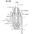
ホゼル及び螺子部材の別の構造例を第9図〜第11図に示す。第9図〜第11図はそれぞれ別の実施の形態に係るヘッドにおける前記第5図と同様部分の断面図であり、同一部分については第5図と同一符号を付してある。 FIGS. 9 to 11 show other structural examples of the hosel and the screw member. 9 to 11 are cross-sectional views of the same parts as those of FIG. 5 in the head according to another embodiment, and the same parts are denoted by the same reference numerals as those of FIG.
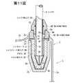
第9図は、請求項3,4の実施の形態に係るものであり、ホゼル3の代わりに、凸部3tよりも上側をカットした形状の短いホゼル3Cを用いている。ホゼル3のうち凸部3tよりも上側の部分は第1の螺子部材9Cによって代替されている。即ち、第1の螺子部材9Cは、前記第5図の第1の螺子部材9と、ホゼル3の凸部3tよりも上側部分と合体させた構成のものである。FIG. 9 relates to the embodiment of
第1の螺子部材9Cの上部内周面には、前記雌螺子3aに相当する雌螺子9mが設けられており、この雌螺子9mに第2の螺子部材6の雄螺子6b(第9図では符号略。第6図参照)を螺合させている。第1の螺子部材9Cの下部内周面に凸部9tが周設されており、シャフトケース5の凸部5tが該凸部9tにスペーサを介して当接している。 A
第1の螺子部材9Cを雌螺子2mにねじ込むことにより、ホゼル3Cが固定される。第2の螺子部材6の雄螺子6bを第1の螺子部材9Cの雌螺子9mにねじ込むことにより、シャフトケース5の凸部5tが第2の螺子部材9Cの凸部9tに押し付けられ、シャフトケース5がホゼル3Cに対し固定される。その他の構成は第1図〜第8図の実施の形態と同じである。 The hosel 3C is fixed by screwing the first screw member 9C into the
第10図では、シャフトケース5Dとして、前記シャフトケース5の凸部5tよりも上側をカットした形状のものが用いられている。第2の螺子部材6Dとして、第5図の第2の螺子部材6と、シャフトケース5の凸部5tよりも上側とを合体させた形状のものが用いられている。シャフト4は、第2の螺子部材6Dのシャフト挿入穴6Hを通ってシャフトケース5Dのシャフト挿入穴5Hに差し込まれている。シャフト4はシャフトケース5Dのシャフト挿入穴5Hの内周面に接着剤で接着されている。第2の螺子部材6Dはシャフト4に対し回転自在に外嵌している。シャフト挿入穴6Hの内周面には、シャフト4の外周面に摺動自在に接するOリング20が設けられており、シャフト4のがたつきを防いでいる。第10図の実施の形態のその他の構成は第1図〜第8図と同じである。 In FIG. 10, a shaft case 5D having a shape in which the upper side of the
第11図は、第10図において、ホゼル3及び第1の螺子部材9を第9図のホゼル3C及び第1の螺子部材9Cに置換したものであり、その他の構成は第10図と同一である。 FIG. 11 is the same as FIG. 10 except that the
これらの第9図〜第11図の実施の形態によっても第1図〜第8図の実施の形態と同様の作用効果が奏される。 The same functions and effects as those of the embodiment of FIGS. 1 to 8 can be obtained by the embodiment of FIGS.
上記ホゼル、シャフトケース及び螺子部材は金属製とされることが好ましく、特にアルミ又はチタンもしくはそれらの合金よりなることが好ましい。ホゼル3,3A,3B,3Cについては、ヘッド本体と同等又はそれよりも低い比重の材質が好ましく、例えばチタン合金、アルミニウム、アルミ合金、マグネシウム合金、FRP、合成樹脂などを用いてもよい。 The hosel, shaft case, and screw member are preferably made of metal, and particularly preferably made of aluminum, titanium, or an alloy thereof. The
ヘッドの材質は特に限定されないが、ウッド型ゴルフクラブヘッドの場合、例えばチタン合金やアルミ合金、ステンレス等とすることができる。 The material of the head is not particularly limited, but in the case of a wood type golf club head, for example, a titanium alloy, an aluminum alloy, stainless steel or the like can be used.
上記実施の形態ではホゼル及びホゼル挿入穴に正四角錐形となるように4面の斜面を設けているが、斜面の数が3又は5以上の正多角錐形でもよい。また、ホゼルの先端側及びホゼル挿入穴の奥部を星型等の凹多角形断面形状やギヤ歯形断面形状としてもよい。 In the above-described embodiment, four inclined surfaces are provided in the hosel and the hosel insertion hole so as to form a regular quadrangular pyramid, but a regular polygonal pyramid having three or five inclined surfaces may be used. Further, the front end side of the hosel and the inner part of the hosel insertion hole may have a concave polygonal cross-sectional shape such as a star shape or a gear tooth cross-sectional shape.
なお、シャフト4に取り付けるグリップとして、断面が非真円形のものを用いることがある。例えば、グリップ外周面のうちアドレス状態で地面を指向する下側面をその他の面よりも膨出した形状とすることがある。このような場合、ホゼル3,3A,3B,3Cの向きを変えたときに、グリップ膨出部が地面側とならないことがある。そこで、本発明では、断面真円形のグリップを用いるのが好ましい。 In addition, as a grip attached to the shaft 4, a grip having a non-circular cross section may be used. For example, the bottom surface of the grip outer peripheral surface that faces the ground in the address state may have a shape that bulges more than other surfaces. In such a case, when the direction of the
上記実施の形態ではゴルフクラブヘッドはウッド型であるが、ユーティリティ型、アイアン型、パターなどのいずれのタイプのゴルフクラブヘッドにも本発明を適用することができる。 In the above embodiment, the golf club head is a wood type, but the present invention can be applied to any type of golf club head such as a utility type, an iron type, or a putter.
なお、図示の中空型のゴルフクラブヘッドの場合、ホゼル3,3A,3B,3C及びホゼル設置部2g並びにシャフトケース5、螺子部材6,6D,9,9Cを設けたことにより、ヒール側の重量が一般的なゴルフクラブヘッドに比べて大きくなる。そのため、トウ側やバック部の肉厚を大きくしたり、トウ側にウェイトを設けたりすることにより、ゴルフクラブヘッドのバランスをとるようにしてもよい。 In the case of the illustrated hollow golf club head, the weight on the heel side is provided by providing the
1 ヘッド
2 ヘッド本体
2a フェース部
2e ヒール部
2g ホゼル設置部
2H ホゼル挿入穴
3,3A,3B,3C ホゼル
3a 雌螺子
3b 段差面
3d 斜面
3H シャフトケース挿入穴
3k 斜面
4 シャフト
5 シャフトケース
5a シャフト挿入穴
5b 小孔
5c 斜面
5g 拡径部
5H シャフト挿入穴
5h 小径部
5t 凸部
6,6D 第2の螺子部材
6b 雄螺子
8,8A 弾性体
9,9C 第1の螺子部材
9t 凸部DESCRIPTION OF
Claims (10)
Translated fromJapanese該ゴルフクラブヘッドは、
ホゼル挿入穴を有したヘッド本体と、
シャフトケース挿入穴を有し、該ホゼル挿入穴に着脱可能に装着されたホゼルと、
前記シャフト挿入穴を有し、該シャフトケース挿入穴に着脱可能に装着されたシャフトケースと、を備えてなり、
該ホゼルは、該ホゼル挿入穴の軸心周りの周方向位相を変更して装着可能であり、且つ、該シャフトケース挿入穴の位置及び角度の少なくとも一方が異なる別のホゼルと交換可能であり、
前記シャフトの軸心が該ホゼル挿入穴の軸心に対し傾斜方向となっており、
該ホゼル挿入穴の入口部の内周面に第1の雌螺子が設けられており、
前記ホゼルに、外周面に第1の雄螺子を有した第1の螺子部材が回転自在にかつ軸心方向移動不能に外嵌しており、
該第1の雄螺子を第1の雌螺子に螺着させることにより、前記ホゼルが前記ヘッド本体に固定されていることを特徴とするゴルフクラブ。Oitethe Gorufukurablankingof the shaft insertion hole of the golf club head tip of the shaft,which are fixed is inserted,
The golf club head
A head body having a hosel insertion hole;
A hosel having a shaft case insertion hole and detachably attached to the hosel insertion hole;
A shaft case having the shaft insertion hole and detachably attached to the shaft case insertion hole;
The hosel, said hosel is attachable by changing the circumferential direction phase around the axis of the insertion hole, and,Ri least one replaceable different separate hosel der position and angle of the shaft case insertion hole,
The axis of the shaft is inclined with respect to the axis of the hosel insertion hole,
A first female screw is provided on the inner peripheral surface of the inlet portion of the hosel insertion hole;
A first screw member having a first male screw on the outer peripheral surface is externally fitted to the hosel so as to be rotatable and immovable in the axial direction.
By screwing the first male screw into the first female screw, Gorufukurablanking, characterized inthat the hosel is fixed to the headbody.
前記シャフトケース挿入穴の入口部の内周面に第2の雌螺子が設けられており、
前記シャフトケースに、外周面に第2の雄螺子を有した第2の螺子部材が回転自在にかつ軸心方向移動不能に外嵌しており、
該第2の雄螺子を第2の雌螺子に螺着させることにより、前記シャフトケースが前記ホゼルに固定されていることを特徴とするゴルフクラブ。In claim1 ,
A second female screw is provided on the inner peripheral surface of the inlet portion of the shaft case insertion hole;
A second screw member having a second male screw on the outer peripheral surface is fitted to the shaft case so as to be rotatable and immovable in the axial direction.
A golf club, wherein the shaft case is fixed to the hosel by screwing the second male screw to a second female screw.
該ゴルフクラブヘッドは、
ホゼル挿入穴を有したヘッド本体と、
シャフトケース挿入穴を有し、該ホゼル挿入穴に着脱可能に装着されたホゼルと、
前記シャフト挿入穴を有し、該シャフトケース挿入穴に着脱可能に装着されたシャフトケースと、を備えてなり、
該ホゼルは、該ホゼル挿入穴の軸心周りの周方向位相を変更して装着可能であり、且つ、該シャフトケース挿入穴の位置及び角度の少なくとも一方が異なる別のホゼルと交換可能であり、
前記シャフトの軸心がホゼル挿入穴の軸心に対し傾斜方向となっており、
該ホゼル挿入穴の入口部の内周面に第1の雌螺子が設けられており、
前記シャフトケースに、外周面に第1の雄螺子を有した第1の螺子部材が回転自在にかつ軸心方向移動不能に外嵌しており、
該第1の雄螺子を第1の雌螺子に螺着させることにより、前記ホゼルが前記ヘッド本体に固定されていることを特徴とするゴルフクラブ。In the golf club in which the tip of the shaft is inserted and fixed in the shaft insertion hole of the golf club head,
The golf club head
A head body having a hosel insertion hole;
A hosel having a shaft case insertion hole and detachably attached to the hosel insertion hole;
A shaft case having the shaft insertion hole and detachably attached to the shaft case insertion hole;
The hosel can be mounted by changing the circumferential phase around the axis of the hosel insertion hole, and can be exchanged with another hosel having a different position and angle of the shaft case insertion hole,
The axis of the shaft is inclined with respect to the axis of the hosel insertion hole,
A first female screw is provided on the inner peripheral surface of the inlet portion of the hosel insertion hole;
A first screw member having a first male screw on the outer peripheral surface is fitted to the shaft case so as to be rotatable and immovable in the axial direction.
A golf club characterized in that the hosel is fixed to the head body by screwing the first male screw to the first female screw.
前記第1の螺子部材の入口部の内周面に第2の雌螺子が設けられており、
前記シャフトケースに、外周面に第2の雄螺子を有した第2の螺子部材が回転自在にかつ軸心方向移動不能に外嵌しており、
該第2の雄螺子を第2の雌螺子に螺着させることにより、前記シャフトケースが前記ホゼルに固定されていることを特徴とするゴルフクラブ。In claim3 ,
A second female screw is provided on the inner peripheral surface of the inlet portion of the first screw member;
A second screw member having a second male screw on the outer peripheral surface is fitted to the shaft case so as to be rotatable and immovable in the axial direction.
A golf club, wherein the shaft case is fixed to the hosel by screwing the second male screw to a second female screw.
前記ホゼルをホゼル挿入穴及びシャフトケースと分離し、該ホゼルをシャフトケース挿入穴の位置又は角度が異なる別のホゼルと交換し、
その後、前記シャフトケースをシャフトケース挿入穴に固定すると共にホゼルをホゼル挿入穴に固定する
ことを特徴とするゴルフクラブの特性調節方法。A method for adjusting characteristics of a golf club according to anyone of claims1 to8 ,
Separating the hosel from the hosel insertion hole and the shaft case, and replacing the hosel with another hosel having a different position or angle of the shaft case insertion hole;
Then, the shaft case is fixed to the shaft case insertion hole and the hosel is fixed to the hosel insertion hole.
予め新たなシャフトを新たなシャフトケースに固着して新たなシャフトケース・シャフト連結体を作成しておき、
ゴルフクラブに取り付けられているシャフトケース・シャフト連結体をヘッドから取り外し、このヘッドに新たなシャフトケース・シャフト連結体を取り付けることを特徴とするゴルフクラブの特性調節方法。A method for adjusting characteristics by replacing the shaft of the golf club according to anyone of claims1 to8 with a new shaft,
A new shaft is fixed to a new shaft case in advance to create a new shaft case / shaft assembly,
A method for adjusting characteristics of a golf club, comprising: removing a shaft case / shaft coupling body attached to the golf club from the head; and attaching a new shaft case / shaft coupling body to the head.
Priority Applications (3)
| Application Number | Priority Date | Filing Date | Title |
|---|---|---|---|
| JP2009142316AJP5359586B2 (en) | 2009-06-15 | 2009-06-15 | Golf club and method for adjusting characteristics thereof |
| US12/646,056US8246484B2 (en) | 2009-06-15 | 2009-12-23 | Golf club, head of golf club and method for adjusting properties of golf club |
| US13/552,228US8628430B2 (en) | 2009-06-15 | 2012-07-18 | Golf club, head of golf club and method for adjusting properties of golf club |
Applications Claiming Priority (1)
| Application Number | Priority Date | Filing Date | Title |
|---|---|---|---|
| JP2009142316AJP5359586B2 (en) | 2009-06-15 | 2009-06-15 | Golf club and method for adjusting characteristics thereof |
Publications (2)
| Publication Number | Publication Date |
|---|---|
| JP2010284408A JP2010284408A (en) | 2010-12-24 |
| JP5359586B2true JP5359586B2 (en) | 2013-12-04 |
Family
ID=43306901
Family Applications (1)
| Application Number | Title | Priority Date | Filing Date |
|---|---|---|---|
| JP2009142316AExpired - Fee RelatedJP5359586B2 (en) | 2009-06-15 | 2009-06-15 | Golf club and method for adjusting characteristics thereof |
Country Status (2)
| Country | Link |
|---|---|
| US (2) | US8246484B2 (en) |
| JP (1) | JP5359586B2 (en) |
Families Citing this family (44)
| Publication number | Priority date | Publication date | Assignee | Title |
|---|---|---|---|---|
| US8641554B1 (en)* | 2004-11-17 | 2014-02-04 | Callaway Golf Company | Golf club with face angle adjustability |
| US8632417B2 (en)* | 2007-08-28 | 2014-01-21 | Nike, Inc. | Releasable and interchangeable connections for golf club heads and shafts |
| US9757627B2 (en) | 2007-12-18 | 2017-09-12 | Acushnet Company | Interchangeable shaft system |
| US8727905B2 (en)* | 2007-12-18 | 2014-05-20 | Acushnet Company | Interchangeable shaft system |
| US8747248B2 (en) | 2007-12-18 | 2014-06-10 | Acushnet Company | Interchangeable shaft system |
| US10188913B2 (en) | 2007-12-18 | 2019-01-29 | Acushnet Company | Interchangeable shaft system |
| US9403067B2 (en) | 2007-12-18 | 2016-08-02 | Acushnet Company | Interchangeable shaft system |
| US8961330B2 (en) | 2007-12-18 | 2015-02-24 | Acushnet Company | Interchangeable shaft system |
| US9764203B2 (en) | 2007-12-18 | 2017-09-19 | Acushnet Company | Interchangeable shaft system |
| US7883430B2 (en)* | 2008-07-22 | 2011-02-08 | Nike, Inc. | Releasable and interchangeable connections for golf club heads and shafts |
| US9561413B2 (en) | 2009-12-23 | 2017-02-07 | Taylor Made Golf Company, Inc. | Golf club head |
| US9259625B2 (en) | 2009-12-23 | 2016-02-16 | Taylor Made Golf Company, Inc. | Golf club head |
| JP5814677B2 (en)* | 2010-09-17 | 2015-11-17 | ダンロップスポーツ株式会社 | Golf club |
| US9320947B2 (en)* | 2010-09-22 | 2016-04-26 | Dunlop Sports Co. Ltd. | Golf club |
| US8925790B1 (en)* | 2011-03-01 | 2015-01-06 | David Edel | Method for attaching the hosel to a putter head |
| US9079078B2 (en) | 2011-12-29 | 2015-07-14 | Taylor Made Golf Company, Inc. | Golf club head |
| US11617927B2 (en) | 2012-09-18 | 2023-04-04 | Taylor Made Golf Company, Inc. | Golf club head |
| JP6064568B2 (en)* | 2012-12-07 | 2017-01-25 | ブリヂストンスポーツ株式会社 | Golf club and method for adjusting characteristics thereof |
| US9427638B2 (en)* | 2013-03-15 | 2016-08-30 | Brainstorm Golf, Inc. | Golf club configured for multiple adjustability |
| US11951366B2 (en) | 2014-04-28 | 2024-04-09 | Parsons Xtreme Golf, LLC | Golf club heads and methods to manufacture golf club heads |
| US11045698B2 (en) | 2014-04-28 | 2021-06-29 | Parsons Xtreme Golf, LLC | Golf club heads and methods to manufacture golf club heads |
| US11583738B2 (en) | 2014-04-28 | 2023-02-21 | Parsons Xtreme Golf, LLC | Golf club heads and methods to manufacture golf club heads |
| US11090535B1 (en) | 2014-04-28 | 2021-08-17 | Parsons Xtreme Golf, LLC | Golf club heads and methods to manufacture golf club heads |
| US11759684B2 (en) | 2014-04-28 | 2023-09-19 | Parsons Xtreme Golf, LLC | Golf club heads and methods to manufacture golf club heads |
| US10960271B2 (en)* | 2017-06-13 | 2021-03-30 | Parsons Xtreme Golf, LLC | Golf club heads and methods to manufacture golf club heads |
| US12036455B2 (en) | 2014-04-28 | 2024-07-16 | Parsons Xtreme Golf, LLC | Golf club heads and methods to manufacture golf club heads |
| US11369849B2 (en) | 2014-04-28 | 2022-06-28 | Parsons Xtreme Golf, LLC | Golf club heads and methods to manufacture golf club heads |
| US11511169B2 (en) | 2014-04-28 | 2022-11-29 | Parsons Xtreme Golf, LLC | Golf club heads and methods to manufacture golf club heads |
| US11517798B2 (en) | 2014-04-28 | 2022-12-06 | Parsons Xtreme Golf, LLC | Golf club heads and methods to manufacture golf club heads |
| US11141635B2 (en) | 2014-04-28 | 2021-10-12 | Parsons Xtreme Golf, LLC | Golf club heads and methods to manufacture golf club heads |
| US10016662B1 (en) | 2014-05-21 | 2018-07-10 | Taylor Made Golf Company, Inc. | Golf club |
| US9757630B2 (en) | 2015-05-20 | 2017-09-12 | Taylor Made Golf Company, Inc. | Golf club heads |
| US9144720B1 (en) | 2014-06-18 | 2015-09-29 | Wilson Sporting Goods Co. | Golf club adjustable hosel assembly |
| US9358429B2 (en) | 2014-06-18 | 2016-06-07 | Wilson Sporting Goods Co. | Golf club adjustable hosel assembly |
| US9144719B1 (en) | 2014-06-18 | 2015-09-29 | Wilson Sporting Goods Co. | Golf club adjustable hosel assembly |
| KR101604329B1 (en)* | 2015-08-13 | 2016-03-28 | 조상훈 | Separation and Connection Golf Grip to prevent Movement |
| US10220267B2 (en)* | 2017-01-27 | 2019-03-05 | Barry Lyn Holtzman | Shaft adapter rotator |
| US12138512B2 (en) | 2022-07-18 | 2024-11-12 | Parsons Xtreme Golf, LLC | Golf club heads and methods to manufacture golf club heads |
| US11839801B2 (en) | 2017-07-17 | 2023-12-12 | Parsons Xtreme Golf, LLC | Golf club heads and methods to manufacture golf club heads |
| US11918869B2 (en) | 2017-07-17 | 2024-03-05 | Parsons Xtreme Golf, LLC | Golf club heads and methods to manufacture golf club heads |
| US10716972B1 (en) | 2019-03-18 | 2020-07-21 | Barry Lyn Holtzman | Offset golf shaft and coupling apparatus |
| USD939652S1 (en) | 2020-05-29 | 2021-12-28 | Parsons Xtreme Golf, LLC | Golf club hosel |
| US12151147B2 (en) | 2021-09-21 | 2024-11-26 | Taylor Made Golf Company, Inc. | Golf club fitting systems |
| US12076625B2 (en) | 2022-07-18 | 2024-09-03 | Parsons Xtreme Golf, LLC | Golf club heads and methods to manufacture golf club heads |
Family Cites Families (15)
| Publication number | Priority date | Publication date | Assignee | Title |
|---|---|---|---|---|
| JP3547272B2 (en)* | 1996-11-08 | 2004-07-28 | 横浜ゴム株式会社 | Golf club head having a function of adjusting loft angle and lie angle |
| JPH11178954A (en) | 1997-12-19 | 1999-07-06 | Bridgestone Sports Co Ltd | Golf club head |
| US5951411A (en)* | 1998-01-05 | 1999-09-14 | Zevo Golf Co., Inc. | Hosel coupling assembly and method of using same |
| JP2000005349A (en) | 1998-06-19 | 2000-01-11 | Akitaka Nakayama | Golf club facilitating shaft exchange and angle adjustment |
| JP2000093569A (en)* | 1998-09-22 | 2000-04-04 | Kazuo Ariyoshi | Structure for connecting head and shaft of gate ball stick |
| JP2003070940A (en) | 2001-09-06 | 2003-03-11 | Fukuju Sato | Golf club head |
| US20040018886A1 (en)* | 2002-07-24 | 2004-01-29 | Burrows Bruce D. | Temporary golf club shaft-component connection |
| US7887431B2 (en)* | 2008-05-16 | 2011-02-15 | Taylor Made Golf Company, Inc. | Golf club |
| US8622847B2 (en)* | 2008-05-16 | 2014-01-07 | Taylor Made Golf Company, Inc. | Golf club |
| JP2005270402A (en)* | 2004-03-25 | 2005-10-06 | Daiwa Seiko Inc | Golf club |
| US7335113B2 (en)* | 2004-11-17 | 2008-02-26 | Callaway Golf Company | Golf club with interchangeable head-shaft connection |
| US7083529B2 (en)* | 2004-11-17 | 2006-08-01 | Callaway Golf Company | Golf club with interchangeable head-shaft connections |
| US20060264266A1 (en)* | 2005-05-17 | 2006-11-23 | Man-Young Jung | Modular golf club |
| JP4709111B2 (en)* | 2006-09-28 | 2011-06-22 | グローブライド株式会社 | Golf club |
| US7931542B2 (en)* | 2007-07-31 | 2011-04-26 | Daiwa Seiko, Inc. | Golf club |
- 2009
- 2009-06-15JPJP2009142316Apatent/JP5359586B2/ennot_activeExpired - Fee Related
- 2009-12-23USUS12/646,056patent/US8246484B2/ennot_activeExpired - Fee Related
- 2012
- 2012-07-18USUS13/552,228patent/US8628430B2/ennot_activeExpired - Fee Related
Also Published As
| Publication number | Publication date |
|---|---|
| JP2010284408A (en) | 2010-12-24 |
| US20100317454A1 (en) | 2010-12-16 |
| US8628430B2 (en) | 2014-01-14 |
| US20120283044A1 (en) | 2012-11-08 |
| US8246484B2 (en) | 2012-08-21 |
Similar Documents
| Publication | Publication Date | Title |
|---|---|---|
| JP5359586B2 (en) | Golf club and method for adjusting characteristics thereof | |
| JP5353473B2 (en) | Golf club, head thereof, and characteristic adjusting method | |
| JP5401951B2 (en) | Golf club, characteristic adjustment method thereof and shaft exchange method | |
| JP5387351B2 (en) | Golf club head and golf club | |
| JP5463864B2 (en) | Golf club head and golf club | |
| JP5262261B2 (en) | Golf club and shaft exchange method | |
| JP5239964B2 (en) | Golf club, shaft insertion depth changing method and shaft exchanging method | |
| US7819754B2 (en) | Golf club with removable components | |
| JP5309801B2 (en) | Golf club and shaft exchange method | |
| JP2012165864A (en) | Golf club and method for adjusting characteristic of the same | |
| JP5521769B2 (en) | Golf club | |
| JP6064568B2 (en) | Golf club and method for adjusting characteristics thereof | |
| JP5447141B2 (en) | Golf club | |
| JP5283901B2 (en) | Golf club | |
| JP5716592B2 (en) | Golf club and method for adjusting characteristics thereof | |
| JP5386932B2 (en) | Golf club, characteristic adjustment method thereof and shaft exchange method | |
| JP5604958B2 (en) | Golf club weight adjustment method | |
| JP2011217916A (en) | Golf club and method of adjusting properties thereof | |
| JP2014121461A (en) | Golf club and method for adjusting its characteristic | |
| JP2014113254A (en) | Golf club and method for adjusting characteristics thereof |
Legal Events
| Date | Code | Title | Description |
|---|---|---|---|
| A621 | Written request for application examination | Free format text:JAPANESE INTERMEDIATE CODE: A621 Effective date:20120413 | |
| A977 | Report on retrieval | Free format text:JAPANESE INTERMEDIATE CODE: A971007 Effective date:20121220 | |
| A131 | Notification of reasons for refusal | Free format text:JAPANESE INTERMEDIATE CODE: A131 Effective date:20130108 | |
| A521 | Written amendment | Free format text:JAPANESE INTERMEDIATE CODE: A523 Effective date:20130228 | |
| A131 | Notification of reasons for refusal | Free format text:JAPANESE INTERMEDIATE CODE: A131 Effective date:20130507 | |
| A521 | Written amendment | Free format text:JAPANESE INTERMEDIATE CODE: A523 Effective date:20130628 | |
| TRDD | Decision of grant or rejection written | ||
| A01 | Written decision to grant a patent or to grant a registration (utility model) | Free format text:JAPANESE INTERMEDIATE CODE: A01 Effective date:20130806 | |
| A61 | First payment of annual fees (during grant procedure) | Free format text:JAPANESE INTERMEDIATE CODE: A61 Effective date:20130819 | |
| R150 | Certificate of patent or registration of utility model | Ref document number:5359586 Country of ref document:JP Free format text:JAPANESE INTERMEDIATE CODE: R150 Free format text:JAPANESE INTERMEDIATE CODE: R150 | |
| R250 | Receipt of annual fees | Free format text:JAPANESE INTERMEDIATE CODE: R250 | |
| R250 | Receipt of annual fees | Free format text:JAPANESE INTERMEDIATE CODE: R250 | |
| R250 | Receipt of annual fees | Free format text:JAPANESE INTERMEDIATE CODE: R250 | |
| LAPS | Cancellation because of no payment of annual fees |