JP5356273B2 - LIGHTING DEVICE AND LIGHTING DEVICE PROVIDED WITH THE LIGHTING DEVICE - Google Patents
LIGHTING DEVICE AND LIGHTING DEVICE PROVIDED WITH THE LIGHTING DEVICEDownload PDFInfo
- Publication number
- JP5356273B2 JP5356273B2JP2010024758AJP2010024758AJP5356273B2JP 5356273 B2JP5356273 B2JP 5356273B2JP 2010024758 AJP2010024758 AJP 2010024758AJP 2010024758 AJP2010024758 AJP 2010024758AJP 5356273 B2JP5356273 B2JP 5356273B2
- Authority
- JP
- Japan
- Prior art keywords
- light
- prism group
- prism
- lighting device
- light source
- Prior art date
- Legal status (The legal status is an assumption and is not a legal conclusion. Google has not performed a legal analysis and makes no representation as to the accuracy of the status listed.)
- Expired - Fee Related
Links
Images


Classifications
- F—MECHANICAL ENGINEERING; LIGHTING; HEATING; WEAPONS; BLASTING
- F21—LIGHTING
- F21V—FUNCTIONAL FEATURES OR DETAILS OF LIGHTING DEVICES OR SYSTEMS THEREOF; STRUCTURAL COMBINATIONS OF LIGHTING DEVICES WITH OTHER ARTICLES, NOT OTHERWISE PROVIDED FOR
- F21V5/00—Refractors for light sources
- F21V5/02—Refractors for light sources of prismatic shape
- F—MECHANICAL ENGINEERING; LIGHTING; HEATING; WEAPONS; BLASTING
- F21—LIGHTING
- F21S—NON-PORTABLE LIGHTING DEVICES; SYSTEMS THEREOF; VEHICLE LIGHTING DEVICES SPECIALLY ADAPTED FOR VEHICLE EXTERIORS
- F21S8/00—Lighting devices intended for fixed installation
- F21S8/08—Lighting devices intended for fixed installation with a standard
- F21S8/085—Lighting devices intended for fixed installation with a standard of high-built type, e.g. street light
- F21S8/086—Lighting devices intended for fixed installation with a standard of high-built type, e.g. street light with lighting device attached sideways of the standard, e.g. for roads and highways
- F—MECHANICAL ENGINEERING; LIGHTING; HEATING; WEAPONS; BLASTING
- F21—LIGHTING
- F21V—FUNCTIONAL FEATURES OR DETAILS OF LIGHTING DEVICES OR SYSTEMS THEREOF; STRUCTURAL COMBINATIONS OF LIGHTING DEVICES WITH OTHER ARTICLES, NOT OTHERWISE PROVIDED FOR
- F21V5/00—Refractors for light sources
- F21V5/007—Array of lenses or refractors for a cluster of light sources, e.g. for arrangement of multiple light sources in one plane
- F—MECHANICAL ENGINEERING; LIGHTING; HEATING; WEAPONS; BLASTING
- F21—LIGHTING
- F21V—FUNCTIONAL FEATURES OR DETAILS OF LIGHTING DEVICES OR SYSTEMS THEREOF; STRUCTURAL COMBINATIONS OF LIGHTING DEVICES WITH OTHER ARTICLES, NOT OTHERWISE PROVIDED FOR
- F21V5/00—Refractors for light sources
- F21V5/04—Refractors for light sources of lens shape
- F—MECHANICAL ENGINEERING; LIGHTING; HEATING; WEAPONS; BLASTING
- F21—LIGHTING
- F21S—NON-PORTABLE LIGHTING DEVICES; SYSTEMS THEREOF; VEHICLE LIGHTING DEVICES SPECIALLY ADAPTED FOR VEHICLE EXTERIORS
- F21S2/00—Systems of lighting devices, not provided for in main groups F21S4/00 - F21S10/00 or F21S19/00, e.g. of modular construction
- F—MECHANICAL ENGINEERING; LIGHTING; HEATING; WEAPONS; BLASTING
- F21—LIGHTING
- F21Y—INDEXING SCHEME ASSOCIATED WITH SUBCLASSES F21K, F21L, F21S and F21V, RELATING TO THE FORM OR THE KIND OF THE LIGHT SOURCES OR OF THE COLOUR OF THE LIGHT EMITTED
- F21Y2105/00—Planar light sources
- F21Y2105/10—Planar light sources comprising a two-dimensional array of point-like light-generating elements
- F—MECHANICAL ENGINEERING; LIGHTING; HEATING; WEAPONS; BLASTING
- F21—LIGHTING
- F21Y—INDEXING SCHEME ASSOCIATED WITH SUBCLASSES F21K, F21L, F21S and F21V, RELATING TO THE FORM OR THE KIND OF THE LIGHT SOURCES OR OF THE COLOUR OF THE LIGHT EMITTED
- F21Y2115/00—Light-generating elements of semiconductor light sources
- F21Y2115/10—Light-emitting diodes [LED]
Landscapes
- Engineering & Computer Science (AREA)
- General Engineering & Computer Science (AREA)
- Non-Portable Lighting Devices Or Systems Thereof (AREA)
Abstract
Description
Translated fromJapanese本発明は、簡易な構成で、配光特性を制御することのできる照明デバイスおよび照明装置に関し、特に、高い照度と広い配光特性とを有する道路灯、防犯灯、街路灯などの照明装置およびその照明装置に好適な照明デバイスに関するものである。 The present invention relates to a lighting device and a lighting device that can control light distribution characteristics with a simple configuration, and in particular, lighting devices such as road lights, security lights, and street lights having high illuminance and wide light distribution characteristics, and The present invention relates to a lighting device suitable for the lighting device.
交通安全、犯罪防止などのために、多数の照明装置が屋外に設置されている。 Many lighting devices are installed outdoors for road safety and crime prevention.
例えば、道路灯においては、運転手が道路状態を確実に把握できること、走行中に照明装置からの光によって視認性が妨げられるのを防ぐことを目的として、照明された道路の平均輝度、輝度の均斉度やグレアに関する評価値が規定されている。 For example, in the case of road lights, the average brightness and brightness of the illuminated road are intended to ensure that the driver can grasp the road condition reliably and to prevent the visibility from being disturbed by light from the lighting device during driving. Evaluation values for uniformity and glare are defined.
一般に道路灯は、設置高さ7〜10m、設置間隔およそ30〜40mで使用される場合が多く、必要とされる配光の特徴としては、照明装置から±65°付近にピークを備え、かつ、±70°以上の光をカットするというような特性が要求される。このような配光特性を実現し、道路灯に要求される規定値のうち、より高い基準をクリアするためには、照明装置の配光を精密に制御する必要がある。 In general, a road light is often used at an installation height of 7 to 10 m and an installation interval of about 30 to 40 m, and the required light distribution has a peak around ± 65 ° from the lighting device, and Therefore, it is required to have a characteristic of cutting light of ± 70 ° or more. In order to realize such a light distribution characteristic and clear a higher standard among the prescribed values required for road lights, it is necessary to precisely control the light distribution of the lighting device.
照明装置の配光特性を制御するための技術として、特許文献1に記載の方法がある。前記特許文献1に記載の照明装置に関しては、リフレクタと呼ばれる反射部材(制光体)を使用して配光特性を制御し、水平方向の光度を大きくしている。 As a technique for controlling the light distribution characteristics of the lighting device, there is a method described in
また、特許文献2には光源と砲弾型のリフレクタから構成される光源体を複数備えた照明装置が記載されている。特許文献2の照明装置は、リフレクタを光源ごとに設けることで、装置の大型化を低減している。
さらに、特許文献3には、凹レンズによって、配光特性を制御する照明装置が記載されている。 Furthermore,
しかしながら、上記従来の照明装置に関しては、以下のような課題がある。 However, the conventional lighting device has the following problems.
近年、省電力化、長寿命化の観点からLED光源を用いた照明装置が多数開発されている。LED光源を用いた照明装置においては、器具光束を確保するために多数のLED光源を並べて使用することが多く、光源面積が大きくなる。 In recent years, many lighting devices using LED light sources have been developed from the viewpoint of power saving and long life. In an illuminating device using an LED light source, a large number of LED light sources are often used side by side in order to secure an instrument light beam, and the light source area becomes large.
このような場合、特許文献1に記載された照明装置のように、リフレクタを用いて配光を制御しようとすると、光は様々な方向からリフレクタに入射するため、形状の設定が困難となるといった課題がある。また、前記課題を避けるために、リフレクタ、プリズムの面積を大きくして光源面積の比率を小さくした場合、照明装置が大型化してしまうという
課題が生じる。In such a case, as in the illumination device described in
また、特許文献2に記載された照明装置は、リフレクタを光源ごとに設けることで、装置の大型化を低減しているが、部品点数が増加する。 Moreover, although the illuminating device described in
また、特許文献3に記載された照明装置は、凹レンズによって、光源の外縁部の光線を広角化することができるものの、光源の中心領域の光線を広角化することはできない。従って、特許文献3の照明装置は、配光特性の制御が不十分である。 Moreover, although the illuminating device described in
また、道路などに設置される照明装置では、道路進行方向・幅方向に平行な2つの面における配光を制御することが重要となるが、光源体の取り付け方法が複雑となり、製造コスト増大の要因となる。 In addition, in a lighting device installed on a road or the like, it is important to control the light distribution on two surfaces parallel to the road traveling direction and the width direction. However, the method of attaching the light source body is complicated, which increases the manufacturing cost. It becomes a factor.
本発明は、上記従来の問題点に鑑みなされたものであって、その目的は、簡易な構成で、配光特性を制御することのできる照明デバイスおよび照明装置を提供することにある。 The present invention has been made in view of the above-described conventional problems, and an object thereof is to provide an illumination device and an illumination apparatus capable of controlling light distribution characteristics with a simple configuration.
本発明の照明デバイスは、上記の課題を解決するために、複数の光源と、上記光源から放射される光に対して入射面および出射面を有する光学部材とを備え、上記出射面には、複数のプリズムから構成される第1のプリズム群が設けられ、上記第1のプリズム群は、上記光源から放射された光線の配光を、上記第1のプリズム群の長手方向と直交する方向に、広角化するようになっていることを特徴としている。 In order to solve the above-described problem, the illumination device of the present invention includes a plurality of light sources and an optical member having an entrance surface and an exit surface with respect to light emitted from the light source. A first prism group composed of a plurality of prisms is provided, and the first prism group distributes the light distribution of the light emitted from the light source in a direction orthogonal to the longitudinal direction of the first prism group. It is characterized by a wide angle.
上記の構成によれば、光学部材の出射面に、第1のプリズム群が設けられている。これにより、第1のプリズム群に入射した光源からの光線は、第1のプリズム群で反射することで、その方向が大きく変化する。具体的には、この光線は、第1のプリズム群の長手方向と直交する方向に拡散する。このため、第1のプリズム群によって、光源から放射される強度の強い光線の方向を、光源が配置されている面の法線方向から傾いた方向に変化させることができる。従って、より広角に配光した照明装置を実現することができる。 According to said structure, the 1st prism group is provided in the output surface of the optical member. Thereby, the direction of the light beam from the light source incident on the first prism group is largely changed by being reflected by the first prism group. Specifically, this light beam diffuses in a direction orthogonal to the longitudinal direction of the first prism group. For this reason, the first prism group can change the direction of a strong light beam emitted from the light source to a direction inclined from the normal direction of the surface on which the light source is disposed. Accordingly, it is possible to realize an illumination device that distributes light at a wider angle.
しかも、上記の構成によれば、複数の光源に対し、1つの光学部材のみで、光源3から放射された光線の配光が広角化される。つまり、特許文献1および2のようなリフレクタを設けることなく、配光特性を制御することができる。 Moreover, according to the above configuration, the light distribution of the light emitted from the
従って、簡易な構成で、配光特性を制御することのできる照明デバイスを実現することができる。 Therefore, it is possible to realize an illumination device that can control light distribution characteristics with a simple configuration.
なお、上記の構成によれば、リフレクタを設けることなく光学部材のみによって配向特性を制御するため、照明デバイスの薄型化および小型化を実現すると共に、組み立てが容易な高性能の照明デバイスを実現することが可能となる。さらに、薄型化および小型化の実現によって、デザイン性にも優れた照明デバイスを提供することもできる。また、リフレクタが不要な分、部品点数の削減によるコスト低減も実現することができる。 In addition, according to said structure, since an orientation characteristic is controlled only by an optical member, without providing a reflector, while realizing the thinning and size reduction of an illumination device, the high performance illumination device which is easy to assemble is implement | achieved. It becomes possible. Furthermore, by realizing a reduction in thickness and size, it is possible to provide a lighting device that is excellent in design. Further, since the reflector is unnecessary, it is possible to realize cost reduction by reducing the number of parts.
本発明の照明デバイスにおいて、上記入射面には、複数のレンズ部が設けられ、上記レンズ部は、上記第1のプリズム群の長手方向に沿って周期的に形成され、上記レンズ部は、上記光源から放射された光線の配光を、上記レンズ部の周期方向に沿って、狭角化するようになっていることが好ましい。 In the illumination device of the present invention, the incident surface is provided with a plurality of lens portions, the lens portions are periodically formed along the longitudinal direction of the first prism group, and the lens portions are It is preferable that the light distribution of the light emitted from the light source is narrowed along the periodic direction of the lens unit.
上記の構成によれば、光学部材の入射面に、第1のプリズム群の長手方向に沿って形成された複数のレンズ部が設けられている。これにより、レンズ部に入射した光源からの光
線は、レンズ部の周期方向に沿って狭角化される。すなわち、レンズ部が、光源から放射された光を集光する。その結果、レンズ部によって、第1のプリズム群とは異なる配光制御を行うことができる。従って、光学部材に形成された第1のプリズム群およびレンズ部によって、2つの軸方向の配光特性を制御し、配光特性を最適化することができる。それゆえ、リフレクタ等を使用せずとも、例えば、道路照明用の照明装置に適した配光分布、照度を有する照明デバイスを実現することができる。According to said structure, the some lens part formed along the longitudinal direction of the 1st prism group is provided in the entrance plane of the optical member. Thereby, the light beam from the light source incident on the lens unit is narrowed along the periodic direction of the lens unit. That is, the lens unit collects light emitted from the light source. As a result, light distribution control different from that of the first prism group can be performed by the lens unit. Therefore, the light distribution characteristics in the two axial directions can be controlled by the first prism group and the lens portion formed on the optical member, and the light distribution characteristics can be optimized. Therefore, for example, an illumination device having a light distribution and illuminance suitable for an illumination device for road illumination can be realized without using a reflector or the like.
本発明の照明デバイスにおいて、上記レンズ部は、柱状凸レンズと、複数のプリズムから構成される第2のプリズム群とからなり、上記柱状凸レンズと第2のプリズム群とが、互い違いに形成されていることが好ましい。 In the illumination device according to the aspect of the invention, the lens unit includes a columnar convex lens and a second prism group including a plurality of prisms, and the columnar convex lens and the second prism group are alternately formed. It is preferable.
上記の構成によれば、レンズ部が、柱状凸レンズと第2のプリズム群とから構成されている。これにより、柱状凸レンズに入射した光線は、その部位が平面である場合よりもその曲率に沿って内側に光路が変化する。一方、第2のプリズム群に入射した光線は、プリズム面で反射することで、その方向が大きく変化することになる。これにより、光学部材から取り出せる光量が増大し、光の利用効率を向上させることができる。また、柱状凸レンズ、第2のプリズム群による集光機能によって、所望の領域を効率よく照明する照明デバイスを実現することができる。 According to said structure, the lens part is comprised from the columnar convex lens and the 2nd prism group. Thereby, the light path of the light beam incident on the columnar convex lens changes inward along the curvature as compared with the case where the portion is a plane. On the other hand, the direction of the light rays incident on the second prism group changes greatly by being reflected by the prism surface. Thereby, the light quantity which can be taken out from an optical member increases, and the utilization efficiency of light can be improved. In addition, an illumination device that efficiently illuminates a desired region can be realized by the light condensing function of the columnar convex lens and the second prism group.
また、第2プリズム群を通過する光の配光は、柱状凸レンズを通過する光とはある程度独立に制御できるので、照度分布設計の自由度が増し、所望の照度分布が得やすくなる。 In addition, since the light distribution passing through the second prism group can be controlled to some extent independent of the light passing through the columnar convex lens, the degree of freedom in illuminance distribution design is increased, and a desired illuminance distribution is easily obtained.
本発明の照明装置は、上記の課題を解決するために、前記いずれかの照明デバイスを備えることを特徴としている。従って、簡易な構成で、配光特性を制御することのできる照明デバイスを備えた照明装置を提供することができる。 In order to solve the above-described problem, an illumination apparatus according to the present invention includes any one of the illumination devices. Therefore, it is possible to provide an illumination device including an illumination device that can control light distribution characteristics with a simple configuration.
以上のように、本発明の照明デバイスおよび照明装置は、複数の光源と、上記光源から放射される光に対して入射面および出射面を有する光学部材とを備え、上記出射面には、複数のプリズムから構成される第1のプリズム群が設けられ、上記第1のプリズム群は、上記光源から放射された光線の配光を、上記第1のプリズム群の長手方向と直交する方向に、広角化するようになっている構成である。それゆえ、簡易な構成で、配光特性を制御することのできる照明デバイスおよび照明装置を提供することができるという効果を奏する。 As described above, the illumination device and the illumination apparatus of the present invention include a plurality of light sources and an optical member having an entrance surface and an exit surface for light emitted from the light source, and the exit surface includes a plurality of light sources. The first prism group is configured by the first prism group, and the first prism group distributes the light distribution of the light emitted from the light source in a direction orthogonal to the longitudinal direction of the first prism group. This is a configuration that is designed to widen the angle. Therefore, it is possible to provide an illumination device and an illumination apparatus capable of controlling the light distribution characteristics with a simple configuration.
以下、本発明を以下の実施の形態により詳細に説明する。なお、以下の説明においては、同一の機能および作用を示す部材については、同一の符号を付し、説明を省略する。 Hereinafter, the present invention will be described in detail with reference to the following embodiments. In the following description, members having the same function and action are denoted by the same reference numerals and description thereof is omitted.
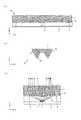
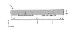
図1は、本実施形態の照明デバイス10を説明するための図であり、(a)は照明デバイス10の外観を示す斜視図であり、(b)は照明デバイス10に設けられた基板2の平面図であり、(c)は照明デバイス10に設けられた光学部材1の出射面1aの平面図であり、(d)は光学部材1の入射面1bの平面図である。 1A and 1B are views for explaining a
図1の(a)に示すように、本実施の形態の照明デバイス10は、光学部材1と、基板2とからなる。ここでは、光の入出力に関する軸方向をZ軸とし、照明デバイス10の長手方向をY軸、短手方向をX軸とする。 As shown to (a) of FIG. 1, the illuminating
図1の(b)に示すように、基板2には複数個の光源3がマトリクス状に配置されている。本実施の形態では、一例として図1の(b)に示すように、光源3は、X方向に平行に1行当たり4個、Y方向に平行に1列当たり20個の計80個配置される例を示す。 As shown in FIG. 1B, the
光源3としては、LEDを用いることができるほか、半導体レーザー等の光源も適用可能である。 As the
光学部材1の表面には、プリズム形状、および柱状凸レンズ形状が形成されている。すなわち、図1の(c)に示すように、光学部材1の出射面1aには、複数のプリズムからなるプリズム群4a,4b(第1のプリズム群)が形成されている。一方、図1の(d)に示すように、光学部材1の入射面1bには、複数のプリズムからなるプリズム群5(第2のプリズム群)および柱状凸レンズ6が形成されている。 A prism shape and a columnar convex lens shape are formed on the surface of the
具体的には、図1の(c)には、光学部材1の出射側に設けられたプリズム群4a,4bの形成領域と、基板2に形成された光源3との位置関係が示されている。プリズム群4a,4bが形成されている部分は、図中の灰色の領域である。図1の(c)の例では、プリズム群4a,4bは、中央2列の各光源3の直上に形成されている。すなわち、プリズム群4a,4bは、中央2列の光源3の長手方向に沿って、出射面1a上に形成されている。それぞれのプリズム群4a、4bは、複数のプリズムを含んでおり、これらのプリズム群4a、4bは互いに離間して設けられている。 Specifically, FIG. 1C shows the positional relationship between the formation region of the
一方、図1(d)には、光学部材1の入射側に設けられたプリズム群5および柱状凸レンズ6の形成領域と、基板2に形成された光源3との位置関係が示されている。光学部材1の入射面1bには、プリズム群5と柱状凸レンズ6とが形成されている。プリズム群5が形成されている部分は、図中の灰色で示された領域である。各プリズム群5は、入射面1bの短手方向に、等間隔で互いに離間して形成される。また各プリズム群5は、複数のプリズムから構成されている。柱状凸レンズ6は、プリズム群5の中間、すなわち、図の
白色の領域に形成されている。図に示すように、プリズム群5は光源3と重ならない領域に形成され、柱状凸レンズ6が光源3の直上の領域に形成されるように、プリズム群5および柱状凸レンズ6が配置されている。つまり、プリズム群5および柱状凸レンズ6は、プリズム群4a,4bの長手方向に沿って、周期的に形成されている。また、本実施形態では、プリズム群5および柱状凸レンズ6は、プリズム群4a,4bの長手方向に沿って、互い違いに形成されている。プリズム群5および柱状凸レンズ6は、光学部材1に入射する光の光路を変換するレンズ部(光路変換部)を構成する。On the other hand, FIG. 1 (d) shows the positional relationship between the formation region of the
次に、図2に基づいて、照明デバイス10における光学部材1の出射面1aの形状について説明する。図2は、図1の照明デバイス10の断面図であり、(a)は図1の(c)のA−A’線断面図であり、(b)は(a)の光学部材1の出射面1aに形成されたプリズム群4aの構造を拡大した図であり、(c)は(a)の光学部材1を介した光線の経路を示す図である。なお、図2の(b)および(c)には、プリズム群4aのみが示されているが、プリズム群4bも同様である。 Next, the shape of the
本実施の形態では、図2の(a)に示すように、一例として、プリズム群4a,4bが10個のプリズムから構成されている。出射面1aに形成されるプリズム群4a,4bの長手方向は、照明デバイス10のY軸方向として設定される。プリズム群4a,4bの中心は、光源3の中心位置の直上となるように設定されている。 In the present embodiment, as shown in FIG. 2A, as an example, the
また、図2の(b)に示すように、プリズム群4aは、光源3の中央とプリズム群4aの中心を通る軸に対して対称的な形状となっている。さらに、プリズム群4aを構成する各プリズムの一方の底角(傾斜角度)θ1、θ2・・・θ5は、異なる角度に設定されている。この例では、図中一点鎖線で示すプリズム群4aの中心軸に遠い方の底角θ1、θ2・・・θ5が、中心軸に近づくにつれて(図中左端から)、徐々に角度が小さくなるように設定されている。また、プリズムの頂角φ1は、すべてのプリズムにおいて同一の角度に設定されている。 As shown in FIG. 2B, the
図2の(c)は、光源3から出射された光がプリズム群4aを介した場合に通過する光線図を示す。光源3から出射された光は、光学部材1に入射し、次いで、出射面1aに形成されたプリズム群4aに到達する。各プリズムのプリズム面の角度は、到達する一部または全部の光線の入射角度が全反射の条件となるように設定されている。このため、プリズム群4aのプリズム面に入射した光線は、プリズム面で全反射することで、その方向が大きく変化する。すなわち、直上方向の光度が強い光源3を用いた場合には、光度の強い光の配光方向が、Z軸に対して大きく変化することになる。つまり、プリズム群4aによって、光源3から放射された光線が拡散され、その光線の配光が広角化される。従って、光源3の直上が相対的に光度が弱くなる配光特性を実現することができる。 FIG. 2C shows a ray diagram through which light emitted from the
このように、プリズム群4aは、光源3から放射された光線の配光を、プリズム群4aの長手方向と直交する方向に、広角化する。 In this way, the
一方、直上にプリズム群4aが形成されていない外側2列の光源3から出射された光線は、光学部材1の入射面1b、出射面1aによるフレネル反射、光学部材1の内部での全反射による影響があるものの、X−Z面内での配光は大きな変化を受けない。そのため、光源3の配光特性をそのまま反映して、この部位からの光は光源3の直上が相対的に光度が強くなる配光特性となる。 On the other hand, the light beams emitted from the two outer rows of
このように、光源3の直上にプリズム群4a,4bが形成されている部位と、形成されていない部位とを組み合わせることで、所望の配光特性を実現することができる。 Thus, a desired light distribution characteristic is realizable by combining the site | part in which the
また、それぞれのプリズムの底角θ1、θ2・・・θ5を変化させることによって、配光を精密に制御することができる。図2の例の場合には、光線がプリズム面に到達する際、入射角度が大きくなるにつれて、プリズムの底角θ1、θ2・・・θ5も大きくなるように変化する。従って、出射光の配光方向が揃うような特性となる。 Further, the light distribution can be precisely controlled by changing the base angles θ1, θ2,... Θ5 of the respective prisms. In the case of the example of FIG. 2, when the light beam reaches the prism surface, the base angles θ1, θ2,... Θ5 of the prism change so as to increase as the incident angle increases. Therefore, the light distribution direction of the emitted light is uniform.
また、プリズム群4a,4bの形状を単純な形状とすることで、光学部材1の作製を容易にするとともに、光学部材1と光源3との位置の位置ずれが有る場合でも、照明特性が変化しにくい照明デバイス10を実現することができる。 Further, by making the
なお、図2に示した例では、プリズム群4a,4bは、光学部材1の作製の容易性と、公差に対する考慮から同じ頂角(φ1)のプリズム形状を備え、かつ中心軸に対して対称的な形状となるような構成を用いている。しかし、プリズム群4a,4bは、この形状に限らず、異なる頂角のプリズムや、中心軸に対して非対称な形状のプリズムから構成されていてもよい。 In the example shown in FIG. 2, the
また、図1の(b)および図2の(a)では、プリズム群4a,4bが、中央2列の光源3の直上に形成されている。しかし、プリズム群4a,4bの形成部位は、これに限定されるものではない。すなわち、プリズム群4a,4bは、図3のように中央の2列でなくてもよい。図3は、照明デバイス10の断面図であり、(a)および(b)は光学部材1の出射面1aに形成された他のプリズム群4a,4bの構造を示す図である。プリズム群4a,4bは、図3の(a)のような外側2列の光源3の直上に形成された構成であってもよいし、図3(b)のような左側2列の光源3の直上に形成された構成などであってもよい。 Further, in FIGS. 1B and 2A, the
このように、本実施形態の照明デバイス10によれば、本来、基板2の光源3が設置された面の法線方向に出射される強度の強い光線の方向を、法線方向に対して大きく傾いた方向に容易に変化させることができる。従って、広い配光特性を備えた照明デバイス10を実現できる。特に道路灯においては、グレアの抑制の観点から照明デバイスを外側に向けた配置によって配光特性を制御することが難しい。このため、本実施の形態の照明デバイス10による配光の制御は、照明デバイス10を備えた道路灯(照明装置)に有効になる。また、道路灯としての要求仕様を高い水準でクリアするためには、より肌理の細かい配光制御が必要になる。照明デバイス10は、光源3の直上にプリズム群4a,4bを形成する部分としない部分を組み合わせることで、細かい配光制御が可能になる。従って、照明デバイス10を備えた道路灯は、道路灯としての要求仕様を高い水準でクリアすることができる。 Thus, according to the
次に、図4に基づいて、照明デバイス10における光学部材1の入射面1bの形状について説明する。図1の照明デバイス10の断面図であり、(a)は図1の(d)のB−B’線断面図であり、(b)は(a)の光学部材1の入射面1bに形成されたプリズム群5の構造を拡大した図であり、(c)は(a)の光学部材1を介した光線の経路を示す図である。 Next, the shape of the
図4の(a)に示すように、光学部材1の入射面1bには、プリズム群5および柱状レンズ6が形成されている。プリズム群5および柱状凸レンズ6は、光学部材1の短手方向に形成されている(図1の(d)参照)。すなわち、プリズム群5および柱状凸レンズ6の長手方向は、X方向となる。図4の(a)では、一例としてプリズム群5が11個のプリズムで形成されている場合を示す。柱状凸レンズ6とプリズム群5は、光学部材1の長手方向に沿って互い違いに配置されている。図4の(a)の例では、柱状凸レンズ6の光軸上に光源3の中心位置が配置されるように設定されている。 As shown in FIG. 4A, a
図4の(b)は、プリズム群5を構成するプリズムの拡大図を示す。プリズム群5は等ピッチで配置された同一形状のプリズムから構成されている。また、プリズムの底辺の角度(底角)θ6、θ7は互いに異なり、θ6<θ7の関係となっている。
FIG. 4B shows an enlarged view of the prisms constituting the
図4の(c)は、図1の(c)のB−B’断面での光線図を示す。光源3から出射された光のうち、光源3直上付近の出射角度の小さい光線は、柱状凸レンズ6に入射し、出射角度の大きな光線はプリズム群5に入射する。柱状凸レンズ6に入射した光線は、その部位が平面である場合よりもその曲率に沿って内側に光路が変化する。一方、各プリズムのプリズム面の角度は、到達する一部または全部の光線の入射角度が全反射の条件となるように設定されている。このため、プリズム群5のプリズム面に入射した光線は、プリズム面で全反射することで、その方向が大きく変化することになる。また、図4の場合、プリズム群5は、個々のプリズムの頂点を通りZ軸に平行な直線に対して非対称な形状のプリズムから構成されている。このため、プリズム群5によって配光される光線方向が、全体的にZ軸方向に対して傾斜する。 FIG. 4C shows a ray diagram at the B-B ′ cross section of FIG. Of the light emitted from the
出射角度の大きな光線は、光学部材1表面の反射や内部での全反射によって損失となりやすい。しかし、図4の(c)のように、光学部材1から出射される光線方向をZ軸に沿う方向に変化させることによって、光学部材1から取り出せる光量が増大し、光の利用効率を向上させることができる。 Light rays having a large emission angle are likely to be lost due to reflection on the surface of the
このように、プリズム群5および柱状凸レンズ6は、光源3から放射された光線の配光を、プリズム群5および柱状凸レンズ6の周期方向に沿って、狭角化する。 In this way, the
また、柱状凸レンズ6、プリズム群5による集光機能によって、所望の領域を効率よく照明する照明デバイス10が実現できる。 Moreover, the
また、プリズム群5を通過する光の配光は、柱状凸レンズ6を通過する光とはある程度独立に制御できるので、照度分布設計の自由度が増し、所望の照度分布が得やすくなる。 In addition, since the light distribution of the light passing through the
また、Y−Z面でみた場合、光学部材1に形成されている柱状凸レンズ6は、それぞれの光源3に1対1で対応するように形成されている。また、プリズム群5は、複数のプリズムから構成されている。これにより、柱状凸レンズ6のレンズの高さや、プリズムのサイズを光源3の大きさ程度に設定することが可能になる。従って、照明装置の薄型化、小型化を実現することができる。 When viewed in the YZ plane, the columnar
また、光源3の発熱により光学部材1の劣化防止を図るため、光学部材1と光源3との距離を離すことが必要となる場合がある。この場合、柱状凸レンズ6だけで光利用効率を向上させるためには、出射角度の大きな光線を集めるために柱状凸レンズ6のサイズ(レンズ高さ)を大きくする必要がある。しかし、プリズム群5にその集光機能を持たせることによって、レンズサイズの大型化を解消することができる。よって、光学部材1を薄型に保ちつつ、光学部材1の劣化を抑制できる。 Further, in order to prevent deterioration of the
なお、光学部材1の入射面1aの形状は、図4の形状に限定されるものではない。図5および図6は、照明デバイス10における光学部材1の入射面1bに形成された他の構造を示す図である。図5に示すように、光源3の中心は、柱状凸レンズ6の中心軸(図中一点鎖線)と一致していなくてもよい。このように、柱状凸レンズ6の光軸と、光源3の光軸とをずらすことによっても、Y−Z面での配光特性を制御することができる。 In addition, the shape of the
また、図6に示すように、光学部材1の入射面に、プリズム群5だけが形成されている構成であってもよい。集光作用がそれほど必要なく、光の利用効率を高めたい場合には、
図6のような構成が有効である。また、光学部材1の作製を容易にすることも可能となる。Moreover, as shown in FIG. 6, the structure by which only the
A configuration as shown in FIG. 6 is effective. In addition, the
光学部材1の材料としては、例えばアクリル樹脂のほか、ポリスチレン樹脂、メタクリル樹脂、ポリカーボネイト樹脂またはガラスなど、可視光域において透明性が良く、透過率の大きなものを用いればよい。 As a material of the
このように、照明デバイス10では、光源3から放射された光は、光学部材1に形成されている柱状凸レンズ6、プリズム群4a,4bおよびプリズム群5により配光制御されることとなる。すなわち、光学部材1の入射面1bに形成された柱状凸レンズ6とプリズム群5とは、光を絞る(狭角化する)機能を有し、光学部材1の出射面1aに形成されたプリズム群4a,4bは光を広げる(広角化する)機能を有している。 As described above, in the
また、入射面1bに形成された柱状凸レンズ6およびプリズム群5と、出射面1aに形成されたプリズム群4a,4bとは、その母線方向が直交している。つまり、柱状凸レンズ6およびプリズム群5の長手方向と、プリズム群4a,4bの長手方向とは、互いに直交している。このため、X−Z面、Y−Z面の2つの面における配光特性を光学部材1のみで個別に制御することができる。 The columnar
次に、照明デバイス10を用いた照明装置について説明する。図7の(a)および(b)は、照明デバイス10を備えた照明装置20の概略図である。図7の(a)に示すように、照明装置20は、本実施の形態で説明した照明デバイス10を2個並列に配置して、かつ紙面下方向に光を放射するように構成される。 Next, an illumination apparatus using the
なお、この実施形態においては、一例として、光源3をX軸方向にピッチ17mmで4列、Y軸方向にピッチ21mmで20列並べた照明デバイス10を、X−Z面で見て平行になるように配置する。光源3の合計個数は80個であり、合計光源光束は10000(lm)である。 In this embodiment, as an example, the
なお、光源3の個数、および、光束については、照明装置20に必要とされる光束の大きさによって適時変更して設定される。 Note that the number of
また、照明装置20において、2つの照明デバイス10は、図7の(a)に示すように平行に配置されるだけでなく、図7の(b)に示すようにある角度Ψを持って配置されていてもよい。この角度Ψは、照明装置20に必要とされるデザインである、図示されていない筐体、カバーなどによって適時変更して設定される。あるいは、この角度Ψは、照明装置20から放射される光を効率的に±X軸方向に広げるためにも、適時変更して設定される。 Further, in the
次に、照明装置20における配光特性について説明する。図8は、図7の(a)の照明装置20における配光特性をシミュレーションした結果を示す図である。図9は、図7の(a)の照明装置20を道路灯として使用した場合の評価条件を説明する図であり、(a)は照明装置20の設置状態を説明する図であり、(b)は照明装置20と観察者23a,23bとの関係を示す図である。 Next, the light distribution characteristic in the
図8では、光源の配光特性として、ランバート分布を仮定した。図8において、実線はX−Z面から16°ずれた平面での配光特性を示している。これは、図9の(a)のように、照明装置20を道路灯に適用する場合、照明装置20が道路22に対して平行ではなく、角度η傾斜して配置される。実線は、図9(a)のように照明装置20が配置された場合の照明装置20の中央と、照明装置20に近い側の車線中央を含む平面での配光特性
に対応する。一方、図8の破線は、Y−Z平面での配光特性を示す。In FIG. 8, a Lambertian distribution is assumed as the light distribution characteristic of the light source. In FIG. 8, the solid line indicates the light distribution characteristic in a plane deviated by 16 ° from the XZ plane. As shown in FIG. 9A, when the
従来の道路灯の配光特性は、光学部材1がない状態ため、光源3と同様に0°方向にピークを持つ配光特性となる。しかし、図8に示すように、照明装置20は、光学部材1の出射面1aに設けられたプリズム群4の作用によって光が広げられる。このため、照明装置20では、±60°付近にピークを持つような配光が実現されている。また、光学部材1の入射面1bに形成されたプリズム群5と柱状凸レンズ6とによって、Y−Z面で光が絞られる(狭角化される)ため、その配光特性が絞られていることが分かる。 The light distribution characteristic of the conventional road light is a light distribution characteristic having a peak in the 0 ° direction as in the
このシミュレーションでは、出射面1aのプリズムの頂角φ1=55°とし、底辺の角度θ1=77°とし、θ5まで3°ずつ小さくなるように設定している(図2の(b)参照)。また、そのプリズムの底面の幅(底辺の長さ)は1mmとした。一方、入射面1bの柱状凸レンズ6として曲率8mmの円柱レンズを用い、プリズム群5におけるプリズムの底辺の角度(底角)θ6=56°,θ7=64°、底面の幅(底辺の長さ)は1mmに設定した。 In this simulation, the apex angle φ1 of the prism on the
また、下記の表1は、本実施形態の照明装置20を道路灯に適用した場合の総合輝度均斉度、車線軸輝度均斉度の値を示す。 Table 1 below shows the values of the overall luminance uniformity and the lane axis luminance uniformity when the

なお、表1に示す各特性値を得るために、道路の反射率としては欧州規格で掲載されている値を使用した。 In addition, in order to obtain each characteristic value shown in Table 1, the value published in the European standard was used as the reflectance of the road.
なお、照明装置20は、図9の(a)に示すようにX方向が道路22の進行方向と平行になるようにした。また、図9の(b)に示すように、照明装置20が連結される灯具の高さは8m、照明装置20が30mの間隔で設置されているとした。道路22の全体の道路幅Wは9mで、対向2車線(一車線4.5m)の道路が想定されている。このとき、図9の(a)に示すηが30°とすると、照明装置20の中央から灯具(照明装置20)に近い側の車線の中央と、灯具の中央から道路22の中央とのなす角ξは約16°となる。総合均斉度は対象となる道路22からd=60m離れた観察者23aと観察者23bとのそれぞれの場所からみた場合の、道路22の最小輝度/平均輝度を表している。観察者23a,23bは、それぞれの車線の中央に位置している。車線軸輝度均斉度は、観察者23aの場合は、対象となる道路において観察者23aからみたL1のライン上の輝度均一性、観察者23bの場合は観察者から見たL2のライン上の輝度均一性をそれぞれ示す。L1は照明装置20からW/4にあるラインであり、L2は照明装置20から3W/4にあるラインである。総合均斉度および車線軸均斉度についてはそれぞれ、0.4以上、0.5以上の値が要求されている。表1に示すように、照明装置20を道路灯に適用した場合、いずれの値も必要な値をクリアしていることがわかる。 The
以上説明したように、本実施形態の照明デバイス10および照明装置20においては、光学部材1の入射面1bに柱状凸レンズ6と、プリズム群5、出射面1aにプリズム群4a,4bを有する光学部材1のみで、2つの面(X−Z面およびY−Z面)の配光特性を制御し、配光特性を最適化することができる。これにより、照明デバイス10を備えた照明装置20は、道路照明に求められる仕様を高い水準でクリアできる道路灯として利用す
ることが可能になる。As described above, in the
また、本実施形態の照明デバイス10および照明装置20では、筐体などをリフレクタとして使用する必要がなくなるため、コンパクトな照明デバイスおよび照明装置を実現することができる。 Further, in the
また、光源3として、光源面積が大きいアレイ状のLED光源を用いた場合においても、各LED光源に対応するように、柱状凸レンズ6およびプリズム群4a,4b,5を形成しているため、大型化を招くことなく配光特性に優れた照明デバイス10および照明装置20を実現することが可能となる。 Further, even when an arrayed LED light source having a large light source area is used as the
なお、本実施形態の照明デバイス10および照明装置20は、電源部および光源3を固定するための筐体、および、カバーなどを備えてもよい。屋外などで使用する照明装置20の場合は、筐体およびカバーを設けることによって、雨、ほこりなどから光源、光学部材1を保護することができる。 In addition, the illuminating
また、上記実施形態の照明デバイス10および前記照明デバイス10を用いた照明装置20は、防犯灯、街路灯、道路灯、公園灯などの屋外照明、その他の照明に幅広く用いることができる。 Moreover, the
また、本実施形態の照明デバイス10は、光学部材1の出射面1aにプリズム群4a,4b、入射面1bにプリズム群5および柱状凸レンズ6が形成されている。また、プリズム群4a,4b、柱状凸レンズ6は、アレイ状に配置された光源3の直上に形成されている。また、プリズム群5は、同一形状,同一ピッチの複数のプリズムからなり、光源3間に形成されている。また、プリズム群5および柱状凸レンズ6は、光を集光する機能を有する。一方、出射面1aに形成されたプリズム群4a,4bは、光を拡散する機能を有する。従って、出射面1aに形成されたプリズム群4a,4bの長手方向と、入射面1bに形成されたプリズム群5および柱状凸レンズ6の長手方向とを直交させることにより、直交する2方向の配向を独立して制御することができる。つまり、プリズム群4a,4b、プリズム群5および柱状凸レンズ6は、配光を制御する光学制御素子として機能する。 In the
本実施形態の照明デバイス10および照明装置20は、このような光学制御素子を用いることにより、1つの部材で(光学部材1のみで)、配光を制御することが可能となる。従って、照明デバイス10および照明装置20の薄型化および小型化を実現すると共に、組み立てが容易な高性能の照明デバイス10および照明装置20を実現することができる。 By using such an optical control element, the
本発明は上述した各実施形態に限定されるものではなく、請求項に示した範囲で種々の変更が可能であり、異なる実施形態にそれぞれ開示された技術的手段を適宜組み合わせて得られる実施形態についても本発明の技術的範囲に含まれる。 The present invention is not limited to the above-described embodiments, and various modifications are possible within the scope shown in the claims, and embodiments obtained by appropriately combining technical means disclosed in different embodiments. Is also included in the technical scope of the present invention.
本発明は、防犯灯、街路灯、道路灯、公園灯などの屋外で使用する照明デバイスおよび前記照明デバイスを用いた照明装置を始め様々な照明装置に幅広く用いるとことができる。 INDUSTRIAL APPLICABILITY The present invention can be widely used in various lighting devices including a lighting device used outdoors such as a crime prevention light, a street light, a road light, and a park light, and a lighting device using the lighting device.
1 光学部材
2 基板
3 光源
4a,4b プリズム群(第1のプリズム群)
5 プリズム群(レンズ部,第2のプリズム群)
6 柱状凸レンズ(レンズ部)
10 照明デバイス
20 照明装置
22 道路
23a 観察者
23b 観察者DESCRIPTION OF
5 Prism group (lens section, second prism group)
6 Columnar convex lens (lens part)
DESCRIPTION OF
Claims (6)
Translated fromJapanese上記光源から放射される光に対して入射面および出射面を有する光学部材とを備え、
上記出射面には、複数のプリズムから構成される第1のプリズム群が設けられ、
上記第1のプリズム群は、上記光源から放射された光線の配光を、上記第1のプリズム群の長手方向と直交する方向に、広角化するようになっており、
上記入射面には、複数のレンズ部が設けられ、
上記レンズ部は、上記第1のプリズム群の長手方向に沿って周期的に形成され、
上記レンズ部は、上記光源から放射された光線の配光を、上記レンズ部の周期方向に沿って、狭角化するようになっており、
上記第1のプリズム群を構成する複数のプリズムは、上記出射面の短手方向の断面形状が、三角形であると共に、各プリズムは、上記第1のプリズム群の中心軸に遠い方の底角が、上記中心軸に近づくにつれて小さくなっていることを特徴とする照明デバイス。Multiple light sources;
An optical member having an entrance surface and an exit surface for the light emitted from the light source,
The exit surface is provided with a first prism group composed of a plurality of prisms,
The first prism group is configured to widen the light distribution of the light emitted from the light source in a direction perpendicular to the longitudinal direction of the first prism group,
The incident surface is provided with a plurality of lens portions,
The lens portion is periodically formed along the longitudinal direction of the first prism group,
The lens unit is configured to narrow the light distribution of the light emitted from the light source along the periodic direction of the lens unit,
The plurality of prisms constituting the first prism group have a triangular cross-sectional shape in the short direction of the exit surface, and each prism has a base angle farther from the central axis of the first prism group. Is smaller as it gets closer to the central axis .
上記柱状凸レンズと第2のプリズム群とが、互い違いに形成されていることを特徴とする請求項1または2に記載の照明デバイス。The lens unit includes a columnar convex lens and a second prism group including a plurality of prisms,
The illumination device according to claim 1, wherein the columnar convex lens and the second prism group are alternately formed.
Priority Applications (5)
| Application Number | Priority Date | Filing Date | Title |
|---|---|---|---|
| JP2010024758AJP5356273B2 (en) | 2010-02-05 | 2010-02-05 | LIGHTING DEVICE AND LIGHTING DEVICE PROVIDED WITH THE LIGHTING DEVICE |
| PCT/JP2010/059722WO2011096098A1 (en) | 2010-02-05 | 2010-06-08 | Lighting device and lighting apparatus provided with lighting device |
| CN2010800594550ACN102686934A (en) | 2010-02-05 | 2010-06-08 | Lighting device and lighting apparatus provided with same |
| US13/514,564US20130003370A1 (en) | 2010-02-05 | 2010-06-08 | Lighting Device And Lighting Apparatus Provided With Lighting Device |
| EP10845230AEP2532954A1 (en) | 2010-02-05 | 2010-06-08 | Lighting device and lighting apparatus provided with lighting device |
Applications Claiming Priority (1)
| Application Number | Priority Date | Filing Date | Title |
|---|---|---|---|
| JP2010024758AJP5356273B2 (en) | 2010-02-05 | 2010-02-05 | LIGHTING DEVICE AND LIGHTING DEVICE PROVIDED WITH THE LIGHTING DEVICE |
Publications (2)
| Publication Number | Publication Date |
|---|---|
| JP2011165409A JP2011165409A (en) | 2011-08-25 |
| JP5356273B2true JP5356273B2 (en) | 2013-12-04 |
Family
ID=44355121
Family Applications (1)
| Application Number | Title | Priority Date | Filing Date |
|---|---|---|---|
| JP2010024758AExpired - Fee RelatedJP5356273B2 (en) | 2010-02-05 | 2010-02-05 | LIGHTING DEVICE AND LIGHTING DEVICE PROVIDED WITH THE LIGHTING DEVICE |
Country Status (5)
| Country | Link |
|---|---|
| US (1) | US20130003370A1 (en) |
| EP (1) | EP2532954A1 (en) |
| JP (1) | JP5356273B2 (en) |
| CN (1) | CN102686934A (en) |
| WO (1) | WO2011096098A1 (en) |
Families Citing this family (62)
| Publication number | Priority date | Publication date | Assignee | Title |
|---|---|---|---|---|
| JP5340763B2 (en)* | 2009-02-25 | 2013-11-13 | ローム株式会社 | LED lamp |
| US10883702B2 (en) | 2010-08-31 | 2021-01-05 | Ideal Industries Lighting Llc | Troffer-style fixture |
| US9822951B2 (en) | 2010-12-06 | 2017-11-21 | Cree, Inc. | LED retrofit lens for fluorescent tube |
| US10309627B2 (en) | 2012-11-08 | 2019-06-04 | Cree, Inc. | Light fixture retrofit kit with integrated light bar |
| US9581312B2 (en) | 2010-12-06 | 2017-02-28 | Cree, Inc. | LED light fixtures having elongated prismatic lenses |
| US9494293B2 (en) | 2010-12-06 | 2016-11-15 | Cree, Inc. | Troffer-style optical assembly |
| US10823347B2 (en) | 2011-07-24 | 2020-11-03 | Ideal Industries Lighting Llc | Modular indirect suspended/ceiling mount fixture |
| WO2013065533A1 (en)* | 2011-10-31 | 2013-05-10 | シャープ株式会社 | Illumination device, backlight, and liquid crystal display device |
| JP6178796B2 (en)* | 2011-11-22 | 2017-08-09 | フィリップス ライティング ホールディング ビー ヴィ | LIGHTING DEVICE AND ROAD LIGHTING EQUIPMENT HAVING THE LIGHTING DEVICE |
| US9423117B2 (en) | 2011-12-30 | 2016-08-23 | Cree, Inc. | LED fixture with heat pipe |
| US10544925B2 (en) | 2012-01-06 | 2020-01-28 | Ideal Industries Lighting Llc | Mounting system for retrofit light installation into existing light fixtures |
| US9777897B2 (en)* | 2012-02-07 | 2017-10-03 | Cree, Inc. | Multiple panel troffer-style fixture |
| US8905575B2 (en) | 2012-02-09 | 2014-12-09 | Cree, Inc. | Troffer-style lighting fixture with specular reflector |
| US9494294B2 (en) | 2012-03-23 | 2016-11-15 | Cree, Inc. | Modular indirect troffer |
| US9310038B2 (en) | 2012-03-23 | 2016-04-12 | Cree, Inc. | LED fixture with integrated driver circuitry |
| US10054274B2 (en) | 2012-03-23 | 2018-08-21 | Cree, Inc. | Direct attach ceiling-mounted solid state downlights |
| US9360185B2 (en) | 2012-04-09 | 2016-06-07 | Cree, Inc. | Variable beam angle directional lighting fixture assembly |
| US9874322B2 (en) | 2012-04-10 | 2018-01-23 | Cree, Inc. | Lensed troffer-style light fixture |
| DE102012206080A1 (en)* | 2012-04-13 | 2013-10-17 | Osram Gmbh | LIGHTING DEVICE FOR ROAD LIGHTING |
| US9285099B2 (en) | 2012-04-23 | 2016-03-15 | Cree, Inc. | Parabolic troffer-style light fixture |
| US8931929B2 (en) | 2012-07-09 | 2015-01-13 | Cree, Inc. | Light emitting diode primary optic for beam shaping |
| US8974077B2 (en) | 2012-07-30 | 2015-03-10 | Ultravision Technologies, Llc | Heat sink for LED light source |
| US9482396B2 (en) | 2012-11-08 | 2016-11-01 | Cree, Inc. | Integrated linear light engine |
| US9441818B2 (en) | 2012-11-08 | 2016-09-13 | Cree, Inc. | Uplight with suspended fixture |
| US9494304B2 (en) | 2012-11-08 | 2016-11-15 | Cree, Inc. | Recessed light fixture retrofit kit |
| US9565782B2 (en) | 2013-02-15 | 2017-02-07 | Ecosense Lighting Inc. | Field replaceable power supply cartridge |
| JP2014165333A (en)* | 2013-02-25 | 2014-09-08 | Kyocera Corp | Light emission device, light emission module and printer |
| US10648643B2 (en) | 2013-03-14 | 2020-05-12 | Ideal Industries Lighting Llc | Door frame troffer |
| US9423104B2 (en) | 2013-03-14 | 2016-08-23 | Cree, Inc. | Linear solid state lighting fixture with asymmetric light distribution |
| US9052075B2 (en) | 2013-03-15 | 2015-06-09 | Cree, Inc. | Standardized troffer fixture |
| JP6274790B2 (en)* | 2013-09-05 | 2018-02-07 | ミネベアミツミ株式会社 | Illumination device and optical member |
| USD786471S1 (en) | 2013-09-06 | 2017-05-09 | Cree, Inc. | Troffer-style light fixture |
| DE102013220550A1 (en)* | 2013-10-11 | 2015-04-16 | Zumtobel Lighting Gmbh | LED grid lamp |
| US9195281B2 (en) | 2013-12-31 | 2015-11-24 | Ultravision Technologies, Llc | System and method for a modular multi-panel display |
| USD772465S1 (en) | 2014-02-02 | 2016-11-22 | Cree Hong Kong Limited | Troffer-style fixture |
| USD807556S1 (en) | 2014-02-02 | 2018-01-09 | Cree Hong Kong Limited | Troffer-style fixture |
| USD749768S1 (en) | 2014-02-06 | 2016-02-16 | Cree, Inc. | Troffer-style light fixture with sensors |
| US10527225B2 (en) | 2014-03-25 | 2020-01-07 | Ideal Industries, Llc | Frame and lens upgrade kits for lighting fixtures |
| JP6143976B1 (en)* | 2014-05-22 | 2017-06-07 | フィリップス ライティング ホールディング ビー ヴィ | Lighting equipment, especially lighting equipment for road lighting |
| US10477636B1 (en) | 2014-10-28 | 2019-11-12 | Ecosense Lighting Inc. | Lighting systems having multiple light sources |
| US9869450B2 (en) | 2015-02-09 | 2018-01-16 | Ecosense Lighting Inc. | Lighting systems having a truncated parabolic- or hyperbolic-conical light reflector, or a total internal reflection lens; and having another light reflector |
| US11306897B2 (en) | 2015-02-09 | 2022-04-19 | Ecosense Lighting Inc. | Lighting systems generating partially-collimated light emissions |
| US9746159B1 (en) | 2015-03-03 | 2017-08-29 | Ecosense Lighting Inc. | Lighting system having a sealing system |
| US9651227B2 (en) | 2015-03-03 | 2017-05-16 | Ecosense Lighting Inc. | Low-profile lighting system having pivotable lighting enclosure |
| US9568665B2 (en) | 2015-03-03 | 2017-02-14 | Ecosense Lighting Inc. | Lighting systems including lens modules for selectable light distribution |
| US9651216B2 (en) | 2015-03-03 | 2017-05-16 | Ecosense Lighting Inc. | Lighting systems including asymmetric lens modules for selectable light distribution |
| US10012354B2 (en) | 2015-06-26 | 2018-07-03 | Cree, Inc. | Adjustable retrofit LED troffer |
| USD785218S1 (en) | 2015-07-06 | 2017-04-25 | Ecosense Lighting Inc. | LED luminaire having a mounting system |
| JP6248988B2 (en)* | 2015-07-07 | 2017-12-20 | 岩崎電気株式会社 | Light emitting element module and lighting apparatus |
| USD782094S1 (en) | 2015-07-20 | 2017-03-21 | Ecosense Lighting Inc. | LED luminaire having a mounting system |
| USD782093S1 (en) | 2015-07-20 | 2017-03-21 | Ecosense Lighting Inc. | LED luminaire having a mounting system |
| US9651232B1 (en) | 2015-08-03 | 2017-05-16 | Ecosense Lighting Inc. | Lighting system having a mounting device |
| US10253948B1 (en) | 2017-03-27 | 2019-04-09 | EcoSense Lighting, Inc. | Lighting systems having multiple edge-lit lightguide panels |
| US11635188B2 (en) | 2017-03-27 | 2023-04-25 | Korrus, Inc. | Lighting systems generating visible-light emissions for dynamically emulating sky colors |
| US12385623B2 (en) | 2016-01-28 | 2025-08-12 | Korrus, Inc. | Beam-shaping lighting systems |
| US11585515B2 (en) | 2016-01-28 | 2023-02-21 | Korrus, Inc. | Lighting controller for emulating progression of ambient sunlight |
| US10365378B2 (en)* | 2016-02-29 | 2019-07-30 | Thermo Eberline Llc | Active dosimeter systems for real-time radiation dose measurements |
| US10641452B2 (en)* | 2018-08-22 | 2020-05-05 | Ford Global Technologies, Llc | Vehicle illumination system having a lens with a sawtooth profile |
| US10775016B1 (en) | 2019-04-04 | 2020-09-15 | Ford Global Technologies, Llc | Vehicle lighting system |
| JP7280126B2 (en)* | 2019-06-28 | 2023-05-23 | コイト電工株式会社 | optical lens |
| JP7389534B2 (en)* | 2019-11-01 | 2023-11-30 | 岩崎電気株式会社 | lighting equipment |
| JP7435326B2 (en)* | 2020-07-06 | 2024-02-21 | 岩崎電気株式会社 | lighting equipment |
Family Cites Families (11)
| Publication number | Priority date | Publication date | Assignee | Title |
|---|---|---|---|---|
| JPH05198205A (en)* | 1991-09-30 | 1993-08-06 | Toshiba Lighting & Technol Corp | Street light |
| JP2002075019A (en)* | 2000-08-25 | 2002-03-15 | Stanley Electric Co Ltd | Vehicle lighting |
| JP4293300B2 (en)* | 2001-05-24 | 2009-07-08 | シャープ株式会社 | Illumination device and display device including the same |
| JP4397910B2 (en)* | 2005-05-20 | 2010-01-13 | 住友化学株式会社 | Surface light source device and transmissive image display device |
| CN100445632C (en)* | 2006-04-27 | 2008-12-24 | 张胜利 | Miner's lamp with flickering light source |
| JP5003298B2 (en)* | 2007-06-13 | 2012-08-15 | 凸版印刷株式会社 | Optical sheet, backlight unit using the same, and display device |
| JP5263658B2 (en) | 2007-11-30 | 2013-08-14 | 東芝ライテック株式会社 | Lighting device |
| JP5182927B2 (en)* | 2008-04-01 | 2013-04-17 | 日亜化学工業株式会社 | Lighting device |
| TW200944696A (en)* | 2008-04-18 | 2009-11-01 | Taiwan Network Comp & Electronic Co Ltd | Light distributing plate having multiple-focus grating |
| CN101571647A (en)* | 2008-04-29 | 2009-11-04 | 精碟科技股份有限公司 | Backlight module and liquid crystal display using the same |
| JP5407054B2 (en)* | 2008-08-01 | 2014-02-05 | 日亜化学工業株式会社 | Lighting device |
- 2010
- 2010-02-05JPJP2010024758Apatent/JP5356273B2/ennot_activeExpired - Fee Related
- 2010-06-08CNCN2010800594550Apatent/CN102686934A/enactivePending
- 2010-06-08USUS13/514,564patent/US20130003370A1/ennot_activeAbandoned
- 2010-06-08EPEP10845230Apatent/EP2532954A1/ennot_activeWithdrawn
- 2010-06-08WOPCT/JP2010/059722patent/WO2011096098A1/enactiveApplication Filing
Also Published As
| Publication number | Publication date |
|---|---|
| JP2011165409A (en) | 2011-08-25 |
| EP2532954A1 (en) | 2012-12-12 |
| US20130003370A1 (en) | 2013-01-03 |
| CN102686934A (en) | 2012-09-19 |
| WO2011096098A1 (en) | 2011-08-11 |
Similar Documents
| Publication | Publication Date | Title |
|---|---|---|
| JP5356273B2 (en) | LIGHTING DEVICE AND LIGHTING DEVICE PROVIDED WITH THE LIGHTING DEVICE | |
| WO2010092834A1 (en) | Lighting device and lighting apparatus using said lighting device | |
| US11473756B2 (en) | Light emitting device with adaptable glare class | |
| US11378244B2 (en) | Headlight apparatus | |
| JP4960406B2 (en) | Light emitting diode light source module | |
| CN102112804B (en) | lighting device | |
| CN105940261B (en) | Lighting device and motor vehicle equipped with same | |
| JP4621779B2 (en) | LIGHTING DEVICE AND LIGHTING DEVICE USING THE LIGHTING DEVICE | |
| JP2012186019A (en) | Lighting device and, lighting fixture equipped with lighting device | |
| JP2017199660A (en) | Motor vehicle headlight module for emitting light beam | |
| WO2012063759A1 (en) | Led lighting device | |
| KR20100126915A (en) | Lens and lighting unit having same | |
| JP2016212962A (en) | Luminaire | |
| JP4631375B2 (en) | Signal light | |
| US10948150B2 (en) | Multi-beam vehicle light | |
| JP5668920B2 (en) | Lighting device | |
| JP2010140878A (en) | Lighting fixture for vehicle | |
| JP6272416B1 (en) | Optical lens, light source unit, and illumination device | |
| JP5693096B2 (en) | Lighting device | |
| KR20110068362A (en) | LED lighting device | |
| JP7670780B2 (en) | Planar lighting device | |
| EP2592334B1 (en) | Lighting for a car parking | |
| JP2012150317A (en) | Lens for lighting and luminaire | |
| CN119677989A (en) | Surface lighting device | |
| CN116490728A (en) | Car light |
Legal Events
| Date | Code | Title | Description |
|---|---|---|---|
| A621 | Written request for application examination | Free format text:JAPANESE INTERMEDIATE CODE: A621 Effective date:20120223 | |
| A131 | Notification of reasons for refusal | Free format text:JAPANESE INTERMEDIATE CODE: A131 Effective date:20130312 | |
| A521 | Written amendment | Free format text:JAPANESE INTERMEDIATE CODE: A523 Effective date:20130430 | |
| A131 | Notification of reasons for refusal | Free format text:JAPANESE INTERMEDIATE CODE: A131 Effective date:20130521 | |
| TRDD | Decision of grant or rejection written | ||
| A01 | Written decision to grant a patent or to grant a registration (utility model) | Free format text:JAPANESE INTERMEDIATE CODE: A01 Effective date:20130730 | |
| A61 | First payment of annual fees (during grant procedure) | Free format text:JAPANESE INTERMEDIATE CODE: A61 Effective date:20130828 | |
| R150 | Certificate of patent or registration of utility model | Free format text:JAPANESE INTERMEDIATE CODE: R150 | |
| LAPS | Cancellation because of no payment of annual fees |