JP5354472B2 - Projection device - Google Patents
Projection deviceDownload PDFInfo
- Publication number
- JP5354472B2 JP5354472B2JP2009258488AJP2009258488AJP5354472B2JP 5354472 B2JP5354472 B2JP 5354472B2JP 2009258488 AJP2009258488 AJP 2009258488AJP 2009258488 AJP2009258488 AJP 2009258488AJP 5354472 B2JP5354472 B2JP 5354472B2
- Authority
- JP
- Japan
- Prior art keywords
- battery
- remaining
- light source
- timing
- detect
- Prior art date
- Legal status (The legal status is an assumption and is not a legal conclusion. Google has not performed a legal analysis and makes no representation as to the accuracy of the status listed.)
- Expired - Fee Related
Links
Images


Landscapes
- Liquid Crystal (AREA)
- Projection Apparatus (AREA)
- Liquid Crystal Display Device Control (AREA)
- Control Of Indicators Other Than Cathode Ray Tubes (AREA)
Abstract
Description
Translated fromJapaneseこの発明は投影装置に関する。 The present invention relates to a projection apparatus.
従来、少なくとも3種の異なる波長毎に分割された映像信号を時分割で表示する表示素子と、異なる波長毎に設けられた光源を、表示素子の時分割の表示期間に合わせかつその表示期間にある表示素子毎に発光させることにより各表示素子を照明する照明手段と、波長毎に分割された1つの映像信号に対応して複数の光源を発光させる表示制御回路とを備えるカラー映像表示装置が知られている(下記公報参照)。 Conventionally, a display element that displays time-division video signals divided for at least three different wavelengths and a light source provided for each different wavelength are matched to the display element's time-division display period and the display period. A color video display device comprising: illumination means for illuminating each display element by causing each display element to emit light; and a display control circuit for emitting a plurality of light sources in response to one video signal divided for each wavelength. It is known (see the following publication).
上記フィールドシーケンシャル方式のカラー映像表示装置では、光源が点滅を繰り返すため、電池電圧が安定しない。例えば、電池の内部抵抗や接点等の接触抵抗を0.4Ω、光源の電流を500mAとした場合、電圧変動は0.2Vとなり、精度よく電池電圧を検出できない。また、電池電圧のチェックは一般的に一定時間毎に行われるが、光源の点滅に応じて電池電圧が変動するため、一定時間毎に電池電圧をチェックした場合、同様に精度よく電池電圧を検出できない。 In the field sequential type color image display device, since the light source repeatedly blinks, the battery voltage is not stable. For example, when the internal resistance of the battery and the contact resistance such as a contact are 0.4Ω and the current of the light source is 500 mA, the voltage fluctuation is 0.2 V, and the battery voltage cannot be detected accurately. In addition, battery voltage is generally checked at regular intervals. However, since battery voltage fluctuates in response to blinking of the light source, battery voltage is detected with high accuracy in the same way when battery voltage is checked at regular intervals. Can not.
この発明はこのような事情に鑑みてなされたもので、その課題は精度よく電池残量を検出することができる投影装置を提供することである。 The present invention has been made in view of such circumstances, and an object thereof is to provide a projection apparatus that can accurately detect the remaining battery level.
上記課題を解決するため請求項1記載の発明は、複数の異なる波長毎に分割された映像信号を時分割で表示する表示素子と、前記異なる波長毎に採用された光源を、前記表示素子の時分割の表示期間に合わせかつ前記表示期間にある表示素子毎に駆動させることにより前記各表示素子を照明する照明手段と、前記光源を駆動させる電池の残量を検出する電池残量検出手段と、前記光源を点灯又は消灯させるタイミング信号を出力するタイミング信号出力手段と、前記タイミング信号出力手段の出力に基づいて前記電池残量検出手段に前記電池の残量の検出を行なわせる制御手段とを備えていることを特徴とする。 In order to solve the above problems, the invention according to claim 1 is directed to a display element that displays a video signal divided for each of a plurality of different wavelengths in a time division manner, and a light source adopted for each of the different wavelengths. Illumination means for illuminating each display element by driving each display element in the display period in accordance with a time-division display period, and battery remaining capacity detection means for detecting the remaining battery level for driving the light source Timing signal output means for outputting a timing signal for turning on or off the light source; and control means for causing the battery remaining amount detecting means to detect the remaining amount of the battery based on an output of the timing signal output means. It is characterized by having.
請求項2に記載の発明は、請求項1記載の投影装置において、前記電池残容量検出手段は、前記電池の電池電圧を検出することを特徴とする。 According to a second aspect of the present invention, in the projection apparatus according to the first aspect, the remaining battery capacity detecting unit detects a battery voltage of the battery.
請求項3に記載の発明は、請求項1又は2記載の投影装置において、前記制御手段は、前記異なる波長のうちの特定の波長の光を発する光源が点灯しているときだけ前記電池残量検出手段に前記電池の残量の検出を行なわせることを特徴とする。 According to a third aspect of the present invention, in the projection apparatus according to the first or second aspect, the control means is configured to provide the remaining battery level only when a light source that emits light of a specific wavelength among the different wavelengths is lit. The detection means is made to detect the remaining amount of the battery.
請求項4に記載の発明は、請求項1又は2記載の投影装置において、前記制御手段は、前記異なる波長毎に採用された光源がそれぞれ点灯しているときに前記電池残量検出手段に前記電池の残量の検出を行なわせることを特徴とする。 According to a fourth aspect of the present invention, in the projection apparatus according to the first or second aspect, the control unit is configured to cause the battery remaining amount detection unit to perform the operation when the light sources employed for the different wavelengths are turned on. It is characterized by detecting the remaining amount of the battery.
請求項5に記載の発明は、請求項1〜4のいずれか1項記載の投影装置において、前記制御手段は、前記光源の点灯開始タイミングより遅れたタイミングで前記電池残量検出手段による前記電池の残量の検出を行なわせることを特徴とする。 According to a fifth aspect of the present invention, in the projection device according to any one of the first to fourth aspects, the control unit is configured to cause the battery to be detected by the remaining battery level detection unit at a timing delayed from a lighting start timing of the light source. It is characterized in that detection of the remaining amount is performed.
請求項6に記載の発明は、請求項1又は2記載の投影装置において、前記制御手段は、前記異なる波長毎に採用された全ての光源が消灯しているとき前記電池残量検出手段に前記電池の残量の検出を行なわせることを特徴とする。 According to a sixth aspect of the present invention, in the projection apparatus according to the first or second aspect, the control unit includes the battery remaining amount detection unit when the light sources employed for the different wavelengths are turned off. It is characterized by detecting the remaining amount of the battery.
請求項7に記載の発明は、請求項6記載の投影装置において、前記制御手段は、前記光源の消灯開始タイミングより遅れたタイミングで前記電池残量検出手段による前記電池の残量の検出を行なわせることを特徴とする。 According to a seventh aspect of the present invention, in the projection apparatus according to the sixth aspect, the control means detects the remaining amount of the battery by the remaining battery amount detecting means at a timing delayed from the turn-off start timing of the light source. It is characterized by making it.
この発明によれば、精度よく電池残量を検出することができる。 According to the present invention, the remaining battery level can be detected with high accuracy.
以下、この発明の実施の形態を図面に基づいて説明する。 Hereinafter, embodiments of the present invention will be described with reference to the drawings.
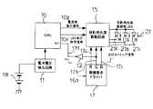
図1はこの発明の第1実施形態に係る投影装置1のブロック図である。 FIG. 1 is a block diagram of a projection apparatus 1 according to the first embodiment of the present invention.
投影装置1は主制御部であるCPU(制御手段)10を備えている。CPU10には、電池18の電圧を検出する電池電圧検出回路(電池残容量検出手段)11と、LED光源(投影用高輝度LED)21a,21b,21cを有し、後述する液晶表示素子(表示素子)30(図6参照)を照明する照明部(照明手段)21と、CPU10からのLED点灯制御信号10c、電流値指示信号10g及び点灯タイミング信号17a,17b,17cに基づいてLED光源21a,21b,21cへの電力供給を制御して、LED光源21a,21b,21cの点灯及び消灯を行う投影用光源駆動回路15と、LED光源21a,21b,21cの点灯又は消灯を制御する点灯タイミング信号17a,17b,17cを出力する画像表示ドライバ(タイミング信号出力手段)17とがそれぞれ接続されている。 The projection apparatus 1 includes a CPU (control means) 10 that is a main control unit. The
電池電圧検出回路11は、図示しないが例えばトランジスタ、抵抗で構成される。CPU10は後述する割り込み信号17d(画像表示ドライバ17の出力)に基づいて電池電圧検出回路11に電池18の電圧の検出を行わせる。 Although not shown, the battery
CPU10は所定のホワイトバランスが得られるようLED光源21a,21b,21cの輝度を変化させる電流値指示信号10gを出力する。LED光源21a,21b,21cから発せられる光の波長はそれぞれ異なる。LED光源21aは赤色LEDであり、LED光源21bは緑色LEDであり、LED光源21cは青色LEDである。 The
また、CPU10はLED光源21a,21b,21cの点灯を制御する電流値指示信号10cを出力する。 Further, the
表示用画像データ処理回路(図示せず)でA/D変換された画像信号16bが画像表示ドライバ17に入力される。画像表示ドライバ17は画像信号16bに基づいて投影用光源駆動回路15を駆動する。 An
画像表示ドライバ17がタイミング信号17a,17b,17cを出力するとき、緑色LED21bを駆動するタイミング信号17bが分岐される。タイミング信号17bはインバータ12によって信号レベルを反転され、割り込み信号17dとしてCPU10の割込み端子INTに入力される。LED21a〜21cは、タイミング信号17a〜17cがLのとき消灯し、Hのとき点灯する。割り込み信号17dはタイミング信号17bがLからHに立ち上がるタイミングでHからLに立ち下がる。すなわち、タイミング信号17bがLからHに立ち上がるタイミングでLレベルの信号が割込み端子INTに入力される。CPU10はLレベルの信号が割込み端子INTに入力されたとき、電池電圧検出回路11に電池18の電圧を検出させる。このとき、CPU10は、電池18の電圧が安定するまで点灯開始タイミングより遅れたタイミングで電池電圧検出回路11に電池18の電圧を検出させる。 When the
次に、図1の投影装置の投影機能を図6に基づいて説明する。 Next, the projection function of the projection apparatus of FIG. 1 will be described with reference to FIG.
図6は投影装置の投影光学系を説明する概念図であり、図1と共通する部分には同一符号を付してその説明を省略する。なお、図6ではLED光源21a〜21cを簡略化して記載した。また、割り込み信号17dの図示を省略した。 FIG. 6 is a conceptual diagram for explaining the projection optical system of the projection apparatus. Parts common to those in FIG. In addition, in FIG. 6,
液晶表示素子30、LED光源21a〜21c、PBS(偏光ビームスプリッタ)ブロック31及び投影レンズ32で投影光学系が構成される。液晶表示素子30は反射型液晶パネルであり、赤(R)、緑(G)、青(B)のLEDを、それぞれの色に対応した液晶表示素子30の表示パターンと同期するよう点灯することによってカラー画像を生成する。 The liquid
LED光源21a〜21cに投影用光源駆動回路15から駆動電流が供給されると、LED光源21a〜21cの光がPBSブロック31に入射する。PBSブロック31に入射した光束は、PBSブロック31で反射され液晶表示素子30に入射する。液晶層を透過した光束は液晶パネルの反射面で反射された後、PBSブロック31へ再度入射する。PBSブロック31に再度入射した光束はPBSブロック31を透過し、投影光として投影レンズ32へ向かって進む。投影レンズ32に入射した光束は投影レンズ32を透過して前方へ放射される。 When drive current is supplied from the projection light
次に、電池18の電圧を検出するタイミングの一例を説明する。 Next, an example of timing for detecting the voltage of the
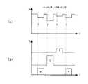
図2(a)は電池電圧を検出するタイミングの一例を示す図、図2(b)はLED光源21a,21b,21cの点灯タイミングの一例を説明する図である。 FIG. 2A is a diagram illustrating an example of timing for detecting the battery voltage, and FIG. 2B is a diagram illustrating an example of lighting timing of the
この例では、緑色(G)のLED21bを点灯させる駆動信号の立ち上がり(点灯開始タイミング)よりやや遅れたタイミングで電池18の電圧が検出される。 In this example, the voltage of the
図3(a)は電池電圧を検出するタイミングの他の例を示す図、図3(b)はLED光源21a,21b,21cの点灯タイミングの他の例を説明する図である。 FIG. 3A is a diagram illustrating another example of the timing for detecting the battery voltage, and FIG. 3B is a diagram illustrating another example of the lighting timing of the
この例は、緑色(G)のLED21bの点灯時に電池18の電圧が複数回(4回)に亘って検出されるようにした点で図2の例と相違する。なお、複数回検出された電池電圧はCPU10で平均されて出力される。 This example is different from the example of FIG. 2 in that the voltage of the
この実施形態によれば、常に緑色(G)のLED21bが点灯している状態で電池電圧が検出されるので、精度よく電池18の電圧を検出することができる。なお、フィールドシーケンシャル方式では、赤色(R)、緑色(G)、青色(B)の各色の光量(単位時間当たりの明るさと点灯時間の積)がおよそ3:6:1:といわれ、緑色(G)の点灯している状態が電池18にとって最も負荷が大きいので、緑色(G)の点灯している状態で電池18の電圧を検出するのが電池寿命を判断するのに都合がよい。また、上記実施形態では、LED21a〜21cを点灯させるHレベルのタイミング信号17a,17b,17cののうちの反転信号(Lレベルの割り込み信号17d)を割込み端子INTに入力させたが、LED21a〜21cを消灯させるLレベルのタイミング信号17a,17b,17cのうちの反転信号(Hレベルの割り込み信号17d)を割込み端子INTに入力させ、投影用光源駆動回路15を制御するようにしてもよい。 According to this embodiment, since the battery voltage is detected while the green (G)
また、図2及び図3の説明では緑色(G)のLED21bの点灯タイミング毎に電池18の電圧の検出を行っているが、CPU10の負荷を減らす目的で、上記LED21bの点灯を2回に1回とか、4回に1回というように電圧の検出回数を間引いてもよい。この場合、画像表示ドライバ17とCPU10の間の回路を工夫することや、CPU10での割り込み処理で、4回のうち無効となる3回は電圧検出を行わないようにするといったプログラム上の工夫で可能となる。 In the description of FIGS. 2 and 3, the voltage of the
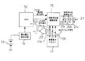
図4はこの発明の第2実施形態に係る投影装置1のブロック図であり、第1実施形態と共通する部分には同一符号を付してその説明を省略する。 FIG. 4 is a block diagram of the projection apparatus 1 according to the second embodiment of the present invention, and parts common to the first embodiment are denoted by the same reference numerals and description thereof is omitted.
この実施形態は、インバータ12に代えてNOR回路22を用いた点で第1実施形態と相違する。 This embodiment is different from the first embodiment in that a NOR
NOR回路22の3つの入力端子にはタイミング信号17a,17b,17cがそれぞれ入力される。タイミング信号17a,17b,17cが入力端子に入力されたとき、タイミング信号17a,17b,17cの少なくとも1つがHレベルであれば、NOR回路22の出力端子からLレベルの信号17dが出力される。そのため、LED21a〜21cをそれぞれ点灯させる駆動信号の立ち上がりに同期して電池18の電圧を検出させることができる(図5参照)。
図5(a)は電池電圧を検出するタイミングの一例を示す図、図5(b)はLED光源21a,21b,21cの点灯タイミングの一例を説明する図である。 FIG. 5A is a diagram illustrating an example of timing for detecting the battery voltage, and FIG. 5B is a diagram illustrating an example of lighting timing of the
この例では、赤色(R)のLED21a、緑色(G)のLED21b及び青色(B)のLED21cのそれぞれを点灯させる駆動信号の立ち上がりに同期して電池18の電圧が検出される。 In this example, the voltage of the
この実施形態によれば、第1実施形態と同様の効果を奏する。なお、この実施形態では3色全てのLED光源21a,21b,21cの点灯タイミングに基づいて電池18の電圧を検出するようにしたが、任意の色(例えば赤色と緑色)LEDに基づいて電池電圧を検出するようにしてもよい。 According to this embodiment, the same effects as those of the first embodiment can be obtained. In this embodiment, the voltage of the
また、図2の上記実施形態ではLED21a〜21cのうちの特定の色のLEDが点灯しているときに電池電圧を検出するようにしたが、全てのLED21a〜21cが消灯しているとき(例えば図2(b)の期間t1)に電池18の電圧を検出するようにしてもよい。このとき、電池18の電圧の検出を消灯開始タイミングよりやや遅れたタイミングで行うのが望ましい。 In the above embodiment of FIG. 2, the battery voltage is detected when the LED of a specific color among the
1:投影装置、10:CPU(制御手段)、11:電池電圧検出回路(電池残量検出手段)、17:画像表示ドライバ(タイミング信号出力手段)、21:照明部(照明手段)、21a,21b,21c:LED光源(光源)、30:液晶表示素子(表示素子)。 1: projection device, 10: CPU (control means), 11: battery voltage detection circuit (remaining battery level detection means), 17: image display driver (timing signal output means), 21: illumination unit (illumination means), 21a, 21b, 21c: LED light source (light source), 30: liquid crystal display element (display element).
Claims (7)
Translated fromJapanese前記異なる波長毎に採用された光源を、前記表示素子の時分割の表示期間に合わせかつ前記表示期間にある表示素子毎に駆動させることにより前記各表示素子を照明する照明手段と、
前記光源を駆動させる電池の残量を検出する電池残量検出手段と、
前記光源を点灯又は消灯させるタイミング信号を出力するタイミング信号出力手段と、
前記タイミング信号出力手段の出力に基づいて前記電池残量検出手段に前記電池の残量の検出を行なわせる制御手段と
を備えていることを特徴とする投影装置。A display element for displaying a video signal divided for each of a plurality of different wavelengths in a time-sharing manner;
Illumination means for illuminating each display element by driving the light source employed for each different wavelength in accordance with the time-division display period of the display element and for each display element in the display period;
Battery remaining amount detecting means for detecting the remaining amount of the battery for driving the light source;
Timing signal output means for outputting a timing signal for turning on or off the light source;
And a control unit that causes the remaining battery level detection unit to detect the remaining battery level based on the output of the timing signal output unit.
Priority Applications (1)
| Application Number | Priority Date | Filing Date | Title |
|---|---|---|---|
| JP2009258488AJP5354472B2 (en) | 2009-11-12 | 2009-11-12 | Projection device |
Applications Claiming Priority (1)
| Application Number | Priority Date | Filing Date | Title |
|---|---|---|---|
| JP2009258488AJP5354472B2 (en) | 2009-11-12 | 2009-11-12 | Projection device |
Publications (2)
| Publication Number | Publication Date |
|---|---|
| JP2011102941A JP2011102941A (en) | 2011-05-26 |
| JP5354472B2true JP5354472B2 (en) | 2013-11-27 |
Family
ID=44193295
Family Applications (1)
| Application Number | Title | Priority Date | Filing Date |
|---|---|---|---|
| JP2009258488AExpired - Fee RelatedJP5354472B2 (en) | 2009-11-12 | 2009-11-12 | Projection device |
Country Status (1)
| Country | Link |
|---|---|
| JP (1) | JP5354472B2 (en) |
Family Cites Families (4)
| Publication number | Priority date | Publication date | Assignee | Title |
|---|---|---|---|---|
| JP3524827B2 (en)* | 1999-09-30 | 2004-05-10 | 三洋電機株式会社 | Battery level indicator for telephone |
| JP2003280607A (en)* | 2002-03-25 | 2003-10-02 | Olympus Optical Co Ltd | Color video display device |
| JP2006330176A (en)* | 2005-05-24 | 2006-12-07 | Olympus Corp | Light source device |
| WO2008139961A1 (en)* | 2007-05-07 | 2008-11-20 | Nikon Corporation | Camera with projection function, portable telephone with projection function and portable electronic apparatus with projection function |
- 2009
- 2009-11-12JPJP2009258488Apatent/JP5354472B2/ennot_activeExpired - Fee Related
Also Published As
| Publication number | Publication date |
|---|---|
| JP2011102941A (en) | 2011-05-26 |
Similar Documents
| Publication | Publication Date | Title |
|---|---|---|
| CN104412318B (en) | Field Sequential Image Display Device in DMD Mode | |
| CN1791298B (en) | Lighting device, liquid crystal display device, mobile terminal device and controlling method thereof | |
| JP6379490B2 (en) | Light source driving device and display device | |
| WO2017057001A1 (en) | Display device | |
| WO2008015953A1 (en) | Image display device | |
| US20060139954A1 (en) | Display system and lighting device used therein | |
| TW200613832A (en) | Module and method for controlling a backlight module and lcd for thereof | |
| JP2011242619A (en) | Image display drive circuit and image display device | |
| US10798348B2 (en) | Light source apparatus, projection type display device and light source control method | |
| JP2007052218A (en) | Projector with imaging function | |
| JP4810941B2 (en) | projector | |
| JP5354472B2 (en) | Projection device | |
| JP2017105291A (en) | Head-up display device | |
| JP7247059B2 (en) | PROJECTION DEVICE, LIGHT SOURCE SYSTEM AND PROJECTION METHOD | |
| US9154754B2 (en) | Projector and method for controlling projector | |
| US8955986B2 (en) | Projection system, lighting device and method for controlling thereof | |
| JP2017227806A (en) | Display device | |
| JP6160078B2 (en) | Image projection device for vehicle | |
| JP2011112754A (en) | Display device | |
| JP4715244B2 (en) | Projection device | |
| JP2018200814A (en) | Display unit | |
| JP2018200813A (en) | Display unit | |
| JP6136215B2 (en) | Light source drive device | |
| JP2012234118A (en) | Projection device | |
| JP2014182157A (en) | Liquid crystal display device and driving method of the same |
Legal Events
| Date | Code | Title | Description |
|---|---|---|---|
| A621 | Written request for application examination | Free format text:JAPANESE INTERMEDIATE CODE: A621 Effective date:20121017 | |
| A977 | Report on retrieval | Free format text:JAPANESE INTERMEDIATE CODE: A971007 Effective date:20130726 | |
| TRDD | Decision of grant or rejection written | ||
| A01 | Written decision to grant a patent or to grant a registration (utility model) | Free format text:JAPANESE INTERMEDIATE CODE: A01 Effective date:20130805 | |
| R150 | Certificate of patent or registration of utility model | Ref document number:5354472 Country of ref document:JP Free format text:JAPANESE INTERMEDIATE CODE: R150 Free format text:JAPANESE INTERMEDIATE CODE: R150 | |
| A61 | First payment of annual fees (during grant procedure) | Free format text:JAPANESE INTERMEDIATE CODE: A61 Effective date:20130818 | |
| R250 | Receipt of annual fees | Free format text:JAPANESE INTERMEDIATE CODE: R250 | |
| R250 | Receipt of annual fees | Free format text:JAPANESE INTERMEDIATE CODE: R250 | |
| R250 | Receipt of annual fees | Free format text:JAPANESE INTERMEDIATE CODE: R250 | |
| R250 | Receipt of annual fees | Free format text:JAPANESE INTERMEDIATE CODE: R250 | |
| R250 | Receipt of annual fees | Free format text:JAPANESE INTERMEDIATE CODE: R250 | |
| R250 | Receipt of annual fees | Free format text:JAPANESE INTERMEDIATE CODE: R250 | |
| LAPS | Cancellation because of no payment of annual fees |