JP5353780B2 - Display control apparatus, method and program - Google Patents
Display control apparatus, method and programDownload PDFInfo
- Publication number
- JP5353780B2 JP5353780B2JP2010059536AJP2010059536AJP5353780B2JP 5353780 B2JP5353780 B2JP 5353780B2JP 2010059536 AJP2010059536 AJP 2010059536AJP 2010059536 AJP2010059536 AJP 2010059536AJP 5353780 B2JP5353780 B2JP 5353780B2
- Authority
- JP
- Japan
- Prior art keywords
- branch road
- image
- blind spot
- guidance
- viewpoint position
- Prior art date
- Legal status (The legal status is an assumption and is not a legal conclusion. Google has not performed a legal analysis and makes no representation as to the accuracy of the status listed.)
- Expired - Fee Related
Links
- 238000000034methodMethods0.000titleclaimsdescription20
- 230000000007visual effectEffects0.000description8
- 238000004891communicationMethods0.000description7
- 238000013459approachMethods0.000description5
- 238000010586diagramMethods0.000description5
- 238000010191image analysisMethods0.000description4
- 230000001133accelerationEffects0.000description3
- 210000003128headAnatomy0.000description3
- 239000003086colorantSubstances0.000description1
- 210000000887faceAnatomy0.000description1
- 230000001771impaired effectEffects0.000description1
- 239000004973liquid crystal related substanceSubstances0.000description1
- 230000004304visual acuityEffects0.000description1
- 239000002699waste materialSubstances0.000description1
Images


Landscapes
- Instrument Panels (AREA)
- Closed-Circuit Television Systems (AREA)
- Controls And Circuits For Display Device (AREA)
- Instructional Devices (AREA)
- Navigation (AREA)
Description
Translated fromJapanese本発明は、案内を表示させる技術に関する。 The present invention relates to a technique for displaying guidance.
フロントウィンドウに案内を表示するにあたり、運転者の頭部の位置に基づいて案内の表示位置を決定するナビゲーション装置が提案されている(特許文献1、参照。)。また、運転者が見ている情景に含まれる建物を地図データに基づいて予測し、当該建物についての案内をフロントウィンドウに表示させるナビゲーション装置が提案されている(特許文献2、参照。)。 A navigation device that determines the display position of guidance based on the position of the driver's head when displaying guidance on the front window has been proposed (see Patent Document 1). In addition, a navigation device has been proposed in which a building included in a scene viewed by a driver is predicted based on map data, and guidance on the building is displayed on a front window (see Patent Document 2).
特許文献1,2のいずれにおいても、フロントウィンドウに案内が表示されるため、フロントウィンドウに表示された案内によって運転者の視界の一部が損なわれるという問題があった。すなわち、フロントウィンドウに案内を表示することにより、フロントウィンドウに案内を表示しない場合よりも運転者の視界が狭くなるという問題があった。
本発明は、前記課題にかんがみてなされたもので、運転者の視界を狭くすることなく案内を表示させる技術を提供することを目的とする。In both
The present invention has been made in view of the above problems, and an object of the present invention is to provide a technique for displaying guidance without narrowing the driver's field of view.
上記の目的を達成するため、本発明において、視点位置情報取得手段が車両における運転者の視点位置を特定する視点位置情報を取得する。位置特定手段は、地図情報に基づいて案内対象物の位置を特定する。さらに、判定手段は、視点位置情報と案内対象物の位置とに基づいて、車両部品によって形成される運転者の死角に案内対象物が存在するか否か判定する。そして、表示制御手段は、死角に案内対象物が存在する場合に、車両部品に備えられた表示部において、案内対象物に関する案内を案内対象物の像に関連づけて表示させる。かかる構成において、案内対象物に関する案内は、運転者の死角を形成する車両部品に備えられた表示部に表示される。運転者の死角を形成しない部位、すなわち運転者の本来の視界において案内を表示しないため、運転者の視界を狭くすることなく案内を表示することができる。また、案内対象物に関する案内が案内対象物の像に関連づけて表示されるため、表示された案内が案内対象物に関するものであることを運転者は容易に認識できる。 In order to achieve the above object, in the present invention, the viewpoint position information acquisition means acquires viewpoint position information for specifying the driver's viewpoint position in the vehicle. The position specifying means specifies the position of the guidance object based on the map information. Further, the determination unit determines whether or not the guidance object exists in the driver's blind spot formed by the vehicle parts based on the viewpoint position information and the position of the guidance object. Then, when the guidance object exists in the blind spot, the display control means causes the display unit provided in the vehicle part to display guidance regarding the guidance object in association with the image of the guidance object. In such a configuration, guidance related to the guidance object is displayed on a display unit provided in a vehicle component that forms the blind spot of the driver. Since the guidance is not displayed in a portion where the driver's blind spot is not formed, that is, in the driver's original field of view, the guidance can be displayed without narrowing the driver's field of view. Further, since the guidance related to the guidance target is displayed in association with the image of the guidance target, the driver can easily recognize that the displayed guidance is related to the guidance target.
視点位置情報は、運転者の視点位置を特定することが可能なものであればよく、必ずしも運転者の眼の位置を直接検出した結果に基づくものでなくてもよい。例えば、運転者の頭部の位置を示す視点位置情報に基づいて、運転者の視点位置を特定してもよい。案内対象物は地図情報に基づいて位置が特定可能なものであればよく、例えば道路や交差点や踏切や信号や交通標識や施設等であってもよい。 The viewpoint position information only needs to be capable of specifying the driver's viewpoint position, and may not necessarily be based on the result of directly detecting the driver's eye position. For example, the driver's viewpoint position may be specified based on viewpoint position information indicating the position of the driver's head. The guidance object only needs to be capable of specifying the position based on the map information, and may be a road, an intersection, a railroad crossing, a signal, a traffic sign, a facility, or the like.
判定手段は、視点位置情報に基づいて車両部品によって形成される死角を特定し、当該特定した死角と案内対象物の位置との関係に基づいて当該死角に案内対象物が存在するか否かを判定する。また、判定手段は、案内対象物の位置に基づいて死角に存在すると予測される案内対象物を予測し、実際に死角を撮影した画像を画像解析することにより、当該案内対象物が死角に存在するか否かを判定してもよい。 The determination means identifies a blind spot formed by the vehicle part based on the viewpoint position information, and determines whether or not the guidance target exists in the blind spot based on the relationship between the identified blind spot and the position of the guidance target. judge. Further, the determination means predicts a guidance target object that is predicted to be present in the blind spot based on the position of the guidance target object, and performs image analysis on an image obtained by actually capturing the blind spot so that the guidance target object exists in the blind spot. It may be determined whether or not to do so.
また、判定手段による判定において、単に案内対象物が死角に存在するか否かだけでなく、案内対象物が死角に存在し、かつ、案内対象物が視点位置に対して所定距離以内に存在するか否かを判定してもよい。所定距離を一般的な視力において視認可能な距離とすることにより、視認可能な範囲に存在する案内対象物に関する案内を表示させることができる。 Further, in the determination by the determination means, not only whether the guidance object exists in the blind spot, but also the guidance object exists in the blind spot, and the guidance object exists within a predetermined distance from the viewpoint position. It may be determined whether or not. By setting the predetermined distance to be a visually recognizable distance with general visual acuity, it is possible to display guidance regarding the guidance object existing in the visually recognizable range.
表示制御手段は、少なくとも案内対象物の像と、当該案内対象物に関する案内とを表示部に表示させればよい。従って、表示制御手段は、案内対象物の像と当該案内対象物に関する案内以外のものを表示させてもよい。例えば、死角に対応する画像を撮影し、当該撮影した画像を表示部に表示すれば、案内対象物の像とともに死角に存在する案内対象物以外の地物の像を含んだ画像を表示部に表示することができる。また、表示部に表示する画像は撮影されたものに限られない。すなわち、表示制御手段は、死角に対応する画像や死角における案内対象物の像を地図情報に基づいて描画し、当該描画した画像を表示部に表示させてもよい。また、表示制御手段は、表示部に表示されない地物についての案内を、案内対象物に関する案内とともに表示させてもよい。なお、車両部品は運転者の死角を形成し、表示部を備えることが可能なものであればよく、ピラーやサンバイザー等であってもよい。 The display control means may display at least an image of the guidance object and guidance regarding the guidance object on the display unit. Accordingly, the display control means may display an image other than the guidance target object image and guidance related to the guidance target object. For example, if an image corresponding to a blind spot is photographed and the photographed image is displayed on the display unit, an image including an image of a feature other than the guidance target existing in the blind spot is displayed on the display unit along with the image of the guidance target. Can be displayed. Further, the image displayed on the display unit is not limited to the captured image. That is, the display control means may draw an image corresponding to the blind spot or an image of the guidance target object at the blind spot based on the map information, and display the drawn image on the display unit. Further, the display control means may display guidance for features that are not displayed on the display unit, together with guidance for guidance objects. The vehicle component may be any component that forms a blind spot of the driver and can include a display unit, and may be a pillar, a sun visor, or the like.
案内対象物に関する案内を案内対象物の像に関連づけて表示するための好適な手法の一例として、案内対象物の像の少なくとも一部に案内対象物に関する案内画像を重畳する手法が挙げられる。これにより、表示された案内が案内対象物に関するものであることを運転者は確実に認識できる。 As an example of a suitable method for displaying guidance related to the guidance target object in association with the image of the guidance target object, there is a technique of superimposing a guidance image related to the guidance target object on at least a part of the image of the guidance target object. Thus, the driver can surely recognize that the displayed guidance is related to the guidance object.
また、案内対象物の像が大きいほど、表示部に表示させる案内画像を大きく表示するようにしてもよい。このようにすることにより、死角に存在する案内対象物が大きいほど案内画像も大きく表示されるため、車両が案内対象物に接近するほど、あるいは、案内対象物自体が大きいほど、案内画像に対する運転者の注意を惹くことができる。 Moreover, you may make it display the guidance image displayed on a display part large, so that the image of a guidance target object is large. By doing so, the larger the guidance object present in the blind spot, the larger the guidance image is displayed. Therefore, the closer the vehicle approaches the guidance object or the larger the guidance object itself, the more the driving for the guidance image is performed. Can attract the attention of a person.
さらに、案内対象物の像が大きいほど案内対象物の像に重畳する案内画像を大きく表示する場合に、案内画像の透明度を案内画像の大きさに応じて変化させてもよい。すなわち、案内画像の大きさが第1の大きさである場合の案内画像の第1透明度よりも、案内画像の大きさが第1の大きさよりも大きい第2の大きさである場合の案内画像の第2透明度を大きくする。これにより、案内画像を大きく表示することにより、当該案内画像に対する注意を惹きつつ、当該案内画像が重畳される案内対象物の像の視認性が低下することが防止できる。 Furthermore, when the guidance image superimposed on the guidance object image is displayed larger as the guidance object image is larger, the transparency of the guidance image may be changed according to the size of the guidance image. That is, the guide image when the size of the guide image is a second size larger than the first size than the first transparency of the guide image when the size of the guide image is the first size. To increase the second transparency. Thereby, it is possible to prevent the visibility of the image of the guidance object on which the guidance image is superimposed from being lowered while attracting attention to the guidance image by displaying the guidance image in a large size.
さらに、本発明のように案内を表示する手法は、プログラムや方法としても適用可能である。また、以上のような装置、プログラム、方法は、単独の装置として実現される場合もあれば、車両に備えられる各部と共有の部品を利用して実現される場合もあり、各種の態様を含むものである。例えば、以上のような装置を備えたナビゲーション装置や方法、プログラムを提供することが可能である。また、一部がソフトウェアであり一部がハードウェアであったりするなど、適宜、変更可能である。さらに、装置を制御するプログラムの記録媒体としても発明は成立する。むろん、そのソフトウェアの記録媒体は、磁気記録媒体であってもよいし光磁気記録媒体であってもよいし、今後開発されるいかなる記録媒体においても全く同様に考えることができる。 Furthermore, the method of displaying guidance as in the present invention can also be applied as a program or method. In addition, the above-described device, program, and method may be realized as a single device or may be realized by using components shared with each part of the vehicle, and include various aspects. It is a waste. For example, it is possible to provide a navigation device, a method, and a program that include the above devices. Further, some changes may be made as appropriate, such as a part of software and a part of hardware. Furthermore, the invention is also established as a recording medium for a program for controlling the apparatus. Of course, the software recording medium may be a magnetic recording medium, a magneto-optical recording medium, or any recording medium to be developed in the future.
ここでは、下記の順序に従って本発明の実施の形態について説明する。
(1)表示システムの構成:
(1−1)ナビゲーション装置の構成:
(1−2)補助表示装置の構成:
(2)表示制御処理:
(2−1)ナビゲーション装置での処理:
(2−2)補助表示装置での処理:
(3)他の実施形態:Here, embodiments of the present invention will be described in the following order.
(1) Configuration of display system:
(1-1) Configuration of navigation device:
(1-2) Configuration of auxiliary display device:
(2) Display control processing:
(2-1) Processing in the navigation device:
(2-2) Processing in auxiliary display device:
(3) Other embodiments:
(1)表示システムの構成:
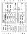
図1は、本発明の一実施形態にかかる表示システム1のブロック図である。表示システム1は、表示制御装置を含むナビゲーション装置10と補助表示装置20とを含んでいる。(1) Configuration of display system:
FIG. 1 is a block diagram of a
(1−1)ナビゲーション装置の構成:
ナビゲーション装置10の構成を示すブロック図である。ナビゲーション装置10は、CPU、RAM、ROM等を備える制御部11と記録媒体12と通信部13とを備えており、制御部11は、記録媒体12やROMに記憶されたプログラムを実行する。このプログラムの一つとしてナビゲーションプログラム100を実行する。記録媒体12には、地図情報12aが記憶され、経路探索がなされた場合には経路情報12bも記憶される。地図情報12aには、車両が走行する道路上に設定されたノードを示すノードデータと、ノード間の道路の形状を特定するための形状補間点データと、ノード同士の連結を示すリンクデータ等が含まれる。通信部13は、制御部11を補助表示装置20と通信可能に接続するインタフェース部である。ノードの位置は所定の測地系に準拠した三次元座標系である地図座標系で表されている。(1-1) Configuration of navigation device:
1 is a block diagram showing a configuration of a
本実施形態においては、ナビゲーションプログラム100による機能を実現するため、車両には、GPS受信部41と車速センサ42とジャイロセンサ43とカメラ44と車内カメラ45と情報受信部46とユーザI/F部47と左カメラ48aと右カメラ48bと左ディスプレイ49aと右ディスプレイ49bとが備えられている。本明細書において、左ディスプレイ49aと右ディスプレイ49bとを、ディスプレイ49a,49bと総称する場合もある。GPS受信部41は、GPS衛星からの電波を受信し、図示しないインタフェースを介して車両の現在位置を算出するための信号を制御部11に出力する。車速センサ42は、車両が備える車輪の回転速度に対応した信号を制御部11に出力する。ジャイロセンサ43は、車両の三次元方向の角加速度を検出し、当該角加速度に対応する信号を制御部11に出力する。制御部11は、角加速度に対応する信号に基づいて、車両前方が向く角度である現在角度を取得する。 In the present embodiment, in order to realize the function by the
カメラ44は、車両の後方の道路を視野に含むように車両に対して取り付けられており、撮影した画像を示す画像データを出力する。制御部11は、図示しないインタフェースを介してこの画像データを取得して画像変換し、道路上の地物を検出して当該地物と車両との相対関係(距離および方向)を特定する。制御部11は、GPS受信部41と車速センサ42とジャイロセンサ43の出力信号、カメラ44が撮影した画像に基づく地物と車両との相対関係、および、地図情報12aに基づいて車両の現在位置を地図座標系において特定する。車両の現在位置は、車両においてGPS受信部41が備えられた位置である基準位置を示す。 The
車内カメラ45は、車両を運転する運転者の眼を視野に含むように車両内に対して取り付けられ、撮影した画像を示す画像データを出力する。制御部11は、図示しないインタフェースを介してこの画像データを取得し、画像に含まれる眼の位置に基づいてGPS受信部41が備えられた基準位置に対する運転者の眼の相対位置を、三次元座標によって特定する。 The in-vehicle camera 45 is attached to the inside of the vehicle so as to include the eyes of the driver who drives the vehicle in the field of view, and outputs image data indicating the photographed image. The
情報受信部46は、外部から受信した電波や赤外線に基づいて道路規制情報等を取得し、当該道路規制情報等を制御部11に出力する。ユーザI/F部47は、運転者の指示を入力し、また運転者に各種の情報を提供するためのインタフェース部であり、図示しないタッチパネルディスプレイやスイッチ、スピーカ等を備えている。 The
左カメラ48aと右カメラ48bは、それぞれ車両の外部における左側前方と右側前方を撮影するためのカメラである。ディスプレイ49a,49bは車両における左右のピラーを運転者側から覆うように備えられる液晶ディスプレイであり、運転者はディスプレイ49a,49bが表示する画像を視認することができる。運転席に着座した運転者が外部を視認した場合に、車両部品としての左右のピラーによって左右の死角がそれぞれ形成される。左カメラ48aと右カメラ48bは、それぞれ前記左右の死角が撮影できるように車両に取り付けられる。また、説明の簡略化のため、本実施形態のディスプレイ49a,49bはそれぞれ矩形平面状であるものとする。 The
次に、ナビゲーションプログラム100の構成について説明する。ナビゲーションプログラム100は、視点位置情報取得部110と経路案内部120と位置特定部130と判定部140と表示制御部150とを備える。視点位置情報取得部110は、運転者の視点位置を特定する視点位置情報を取得する機能を制御部11に実行させる。なお、視点位置とは、地図座標系において特定される運転者の眼の位置である。現在位置はGPS受信部41が備えられた基準位置を示し、相対位置は基準位置に対する運転者の眼の位置を示すため、視点位置情報取得部110の機能により制御部11は、現在位置と相対位置とに基づいて、地図座標系における視点位置を特定することができる。 Next, the configuration of the
経路案内部120は、地図情報12aに基づいて目的地までの経路探索を行い、当該経路探索により得られた経路情報12bを生成し、記録媒体12に記憶させる機能を制御部11に実行させる。経路情報12bにおいては、現在位置から目的地までの案内経路上に存在する地図情報12aのノードが特定される。案内経路上に存在するノードは、主として道路上の交差点が対応付けられたノードである。 The
位置特定部130は、地図情報12aに基づいて案内対象物の位置を特定する機能を制御部11に実行させる。まず、位置特定部130の機能により制御部11は、運転者に案内すべき案内対象物を特定する。具体的には、位置特定部130の機能により制御部11は、地図情報12aを参照して車両の前方の所定距離以内の区間に交差点があるか否かをと判定し、車両の前方に交差点がある場合には当該交差点から分岐する分岐道路を案内対象物として特定する。案内対象物としての分岐道路が特定できると、位置特定部130の機能により制御部11は、当該特定した分岐道路の位置を地図情報12aに基づいて特定する。 The
判定部140は、視点位置と案内対象物としての分岐道路の位置とに基づいて、左右のピラーによってそれぞれ形成される運転者の死角に案内対象物が存在するか否か判定する機能を制御部11に実行させる。まず、判定部140の機能により制御部11は、車両の現在位置と視点位置とディスプレイ49a,49bの位置とを取得するとともに、ジャイロセンサ43の出力信号に基づく車両の現在角度を取得する。これらの情報に基づいて、判定部140の機能により制御部11は、左右のピラーによってそれぞれ形成される運転者の死角を特定する。なお、本実施形態では、運転者の視界において左右のピラーが占める領域と、運転者の視界においてディスプレイ49a,49bの領域とは、互いに同じであることとする。従って、左右のピラーによって形成される死角はディスプレイ49a,49bが形成する死角と同一とみなし、ディスプレイ49a,49bの位置に基づいて左右のピラーによってそれぞれ形成される運転者の死角を特定するものとする。 The
図2A,2Bは運転者の死角を特定する様子を車両上方および側方から見て示す模式図である。判定部140の機能により制御部11は、車両においてGPS受信部41が備えられた基準位置を示す現在位置、車両の基準位置に対するディスプレイ49a,49bの位置、および、車両の現在角度に基づいて、ディスプレイ49a,49bの位置を地図座標系において特定する。なお、基準位置に対するディスプレイ49a,49bの位置は既知の値であり、予め判定部140に組み込まれている。 FIGS. 2A and 2B are schematic views showing how the driver's blind spot is identified as viewed from above and from the side of the vehicle. Based on the function of the
判定部140の機能により制御部11は、視点位置Vとディスプレイ49a,49bの各端部を結んだ放射状の直線によって囲まれる領域を死角Dとして特定する。さらに、判定部140の機能により制御部11は、案内対象物としての分岐道路Bの位置を取得し、死角Dのうち視点位置Vから視認距離S以内の範囲に分岐道路Bが存在するか否かを、左右の死角Dのそれぞれについて判定する。前記視認距離Sは、運転者が案内対象物としての分岐道路Bが視認可能な上限の距離に基づいて設定され、例えば300mとされる。分岐道路Bの形状に応じて視認距離Sを変化させてもよい。 With the function of the
表示制御部150は、死角Dに案内対象物としての分岐道路Bが存在する場合に、分岐道路Bに関する案内を分岐道路Bの像に関連づけて表示部に表示させる機能を制御部11に実行させる。まず、判定部140の機能により死角D内において分岐道路Bが視認可能に存在すると判定された場合に、表示制御部150の機能により制御部11は、当該分岐道路Bに関する案内として分岐道路情報を取得する。分岐道路情報は、分岐道路Bを道なりに走行した場合に到達することが可能な主要な地名を表し、地図情報12aに基づいて得ることができる。次に、表示制御部150の機能により制御部11は、地図情報12aにより分岐道路Bの位置と形状を特定し、死角Dにおける分岐道路Bの範囲を特定する。 The
図2A,図2Bに示すように、車両が走行中の走行道路に対して直線の分岐道路Bが直交する場合を例に挙げて説明する。この場合、死角Dの鉛直方向の全体角度αのうち分岐道路Bは一定の占有角度βを占めることとなる。また、表示制御部150の機能により制御部11は、分岐道路Bの占有角度βを死角Dの全体角度αで除算した占有率β/αを取得する。表示制御部150の機能により制御部11は、占有率β/αが所定の閾値(例えば50%)以下である場合に案内画像の透明度Tを第1の透明度T1とし、占有角度βが前記閾値よりも大きい場合に案内画像の透明度Tを第1の透明度T1よりも大きい第2の透明度T2と設定する。例えば、T1=30[%],T2=60[%]とする。As shown in FIGS. 2A and 2B, the case where a straight branch road B is orthogonal to the traveling road on which the vehicle is traveling will be described as an example. In this case, the branch road B occupies a fixed occupancy angle β out of the vertical angle of the blind spot D in the vertical direction. Further, the function of the
さらに、表示制御部150の機能により制御部11は、死角Dの上端から分岐道路Bが占める範囲の上端までの角度γを、死角Dの全体角度αで除算した上端比γ/αを取得する。そして、表示制御部150の機能により制御部11は、死角Dにおいて視認可能に存在する分岐道路Bについての分岐道路情報を含む案内表示指示を左右の死角Dのそれぞれについて生成し、当該案内表示指示を通信部13を介して補助表示装置20に送信する。この案内表示指示においては、死角Dにおける分岐道路Bの占有率β/αと上端比γ/αと案内画像の透明度Tとが、分岐道路情報に対応付けられて格納される。この案内表示指示に基づいて、補助表示装置20は、案内対象物としての分岐道路Bに関する案内としての分岐道路情報を分岐道路Bの像に関連づけてディスプレイ49a,49bに表示させることができる。 Further, by the function of the
(1−2)補助表示装置の構成:
補助表示装置20は、CPU、RAM、ROM等を備える制御部21と記録媒体22と通信部23とを備えており、制御部21は、記録媒体12やROMに記憶されたプログラムを実行する。このプログラムの一つとして補助表示プログラム200を実行する。通信部23は、制御部21をナビゲーション装置10と通信可能に接続するインタフェース部である。(1-2) Configuration of auxiliary display device:
The
補助表示プログラム200は、死角画像生成部210と重畳出力部220とを備える。死角画像生成部210は、死角画像を生成する機能を制御部21に実行させる。まず、死角画像生成部210の機能により制御部21は、ナビゲーション装置10の制御部11が視点位置情報取得部110の機能により視点位置を特定するのと同様の手法により、視点位置を特定する。さらに、死角画像生成部210の機能により制御部21は、ナビゲーション装置10の制御部11が判定部140の機能により左右の死角Dを特定するのと同様の手法により、視点位置に基づいて左右の死角Dを特定する。 The
さらに、死角画像生成部210の機能により制御部21は、左カメラ48aと右カメラ48bの視野範囲H(図2A,2B、参照。)を取得し、左カメラ48aと右カメラ48bとがそれぞれ撮影した画像データにおける左右の死角Dの画素範囲をそれぞれ特定する。左カメラ48aと右カメラ48bの視野範囲Hは既知であり、視野範囲Hを示す情報が死角画像生成部210に組み込まれている。なお、視野範囲Hは死角Dよりも十分に広く、視点位置Vが変動しても視野範囲Hに死角Dが含まれるように左カメラ48aと右カメラ48bが備えられている。視野範囲Hと死角Dとの相対関係から左カメラ48aと右カメラ48bとが撮影した画像データにおいて左右の死角Dを結像した画素範囲を特定することができる。死角画像生成部210の機能により制御部21は、左カメラ48aと右カメラ48bとが撮影した画像データから、それぞれ左右の死角Dの画素範囲に属する画素を切り出すことにより、左右の死角画像を生成する。 Further, by the function of the blind spot
重畳出力部220は、案内表示指示に基づいてディスプレイ49a,49bに表示を行う機能を制御部21に実行させる。まず、重畳出力部220の機能により制御部21は、ナビゲーション装置10の表示制御部150の機能により送信された案内表示指示を受け付ける。次に、重畳出力部220の機能により制御部21は、分岐道路Bについての分岐道路情報に基づいて案内画像(分岐道路Bを道なりに走行した場合に到達することが可能な主要な地名のアイコン)を生成する。このとき、重畳出力部220の機能により制御部21は、死角画像の鉛直方向の画素数に占有率β/αを乗算した値が案内画像の鉛直方向の画素数となる画像サイズで案内画像を生成する。すなわち、死角画像における分岐道路Bの像が大きいほど、分岐道路Bについての分岐道路情報を示す案内画像を大きくする。車両が分岐道路Bに接近すれば、死角画像における分岐道路Bの像も大きくなるため、車両が分岐道路Bに接近するほど案内画像も大きくなる。 The
案内画像が生成できると、重畳出力部220の機能により制御部21は、死角画像に案内画像を重畳する。このとき、重畳出力部220の機能により制御部21は、死角画像の鉛直方向の画素数に上端比γ/αを乗算した画素数を算出し、当該画素数の分だけ死角画像の上端から下側の画素に案内画像の上端の画素が重畳されるように、案内画像の重畳位置を決定する。すなわち、死角画像における分岐道路Bの像に分岐道路Bについての分岐道路情報を示す案内画像が重畳することにより、分岐道路Bの像と案内画像との関連づけがなされる。さらに、重畳出力部220の機能により制御部21は、死角画像に案内画像を重畳する際の案内画像の透明度を透明度Tとする。すなわち、死角画像における案内画像の占有率β/αが前記閾値よりも大きい場合に案内画像の透明度Tが第1の透明度T1よりも大きい第2の透明度T2と設定する。これにより、死角画像における案内画像の占有率が所定の基準よりも大きい場合には、案内画像の透明度Tを大きくすることができる。
重畳出力部220の機能により制御部21は、案内画像が重畳された死角画像をディスプレイ49a,49bに表示させる。When the guide image can be generated, the
With the function of the superimposed
以上のようにしてディスプレイ49a,49bに表示される死角画像においては、左右のピラーによって形成される死角Dに相当する画像が表示されるため、本来であれば左右のピラーによって視認できない死角Dの様子を運転者が視認することが可能となる。また、死角Dに案内対象物としての分岐道路Bが含まれる場合に、当該分岐道路Bについての分岐道路情報を示す案内画像がディスプレイ49a,49bに表示されるため、ディスプレイ49a,49bに表示された分岐道路Bについての分岐道路情報を運転者が認知することができる。案内画像は、死角Dを形成する左右のピラーの運転者側に備えられたディスプレイ49a,49bに表示されるため、運転者の本来の視界を狭くさせることもない。さらに、死角画像における分岐道路Bの像に当該分岐道路Bについての分岐道路情報を示す案内画像が関連づけられるため、案内画像が示す分岐道路情報が分岐道路Bに関するものであることを運転者が容易に認識できる。特に、死角画像における分岐道路Bの像に案内画像が重畳されるため、案内画像が分岐道路Bに関するものであることを確実に運転者に認識させることができる。 In the blind spot image displayed on the
また、死角画像における分岐道路Bの像が大きいほど案内画像も大きくなるため、車両が分岐道路Bに接近するほど、あるいは、分岐道路B自体が大きい(道幅が広い)ほど、案内画像に対する運転者の注意を惹くことができる。さらに、案内画像が一定の基準よりも大きくなると案内画像の透明度Tを大きくするため、死角画像が示す死角Dの視認性が案内画像によって妨げられることが防止できる。なお、死角画像における分岐道路Bの像が大きいほど案内画像も大きくするように指定できればよく、占有率β/α以外のパラメータによって案内画像の大きさを指定してもよい。例えば、車両の分岐道路Bとの距離の逆数に比例した大きさを有するパラメータによって、案内画像の大きさを指定してもよい。また、分岐道路Bの像が示す道幅と、案内画像の鉛直方向の大きさを同等とするものに限らず、分岐道路Bの像が示す道幅の所定割合の大きさを案内画像の鉛直方向の大きさとして指定してもよい。 Further, the larger the image of the branch road B in the blind spot image, the larger the guide image becomes. Therefore, the closer the vehicle approaches the branch road B or the larger the branch road B itself (the wider the road), the driver for the guide image. Can attract attention. Furthermore, since the transparency T of the guide image is increased when the guide image becomes larger than a certain reference, it is possible to prevent the visibility of the blind spot D indicated by the blind spot image from being hindered by the guide image. Note that it is only necessary to specify that the guidance image is enlarged as the image of the branch road B in the blind spot image is larger, and the size of the guidance image may be specified by a parameter other than the occupation ratio β / α. For example, the size of the guidance image may be specified by a parameter having a size proportional to the reciprocal of the distance from the branch road B of the vehicle. Further, the road width indicated by the image of the branch road B and the vertical size of the guide image are not limited to be equal, but the predetermined ratio of the road width indicated by the image of the branch road B is set in the vertical direction of the guide image. You may specify it as a size.
(2)表示制御処理:
次にナビゲーション装置10と補助表示装置20とが実行する表示制御処理の流れを説明する。表示制御処理は、車両走行時において所定の時間周期で実行するループ処理であり、ナビゲーション装置10が行う処理と、補助表示装置20が行う処理とに区分される。(2) Display control processing:
Next, a flow of display control processing executed by the
(2−1)ナビゲーション装置での処理:
図3は、ナビゲーション装置10にて実行される表示制御処理のフローチャートである。ステップS100において、視点位置情報取得部110の機能により制御部11は、車両の現在位置と、運転者の眼の相対位置とに基づいて運転者の視点位置Vを特定する視点位置情報を取得する。ステップS105において、位置特定部130の機能により制御部11は、記録媒体12から経路情報12bを取得する。経路案内部120の機能により予め経路情報12bが記録媒体12に記憶されている場合には、経路情報12bが取得できる。(2-1) Processing in the navigation device:
FIG. 3 is a flowchart of the display control process executed by the
ステップS110においては、位置特定部130の機能により制御部11は、経路情報12bに基づいて案内経路上の交差点である案内交差点を特定し、当該案内交差点が車両の前方所定距離以内に存在するか否かを判定する。案内交差点が車両の前方の所定距離以内に存在するか否かは、案内交差点に対応するノードの位置と、現在位置とに基づいて判定することができる。所定距離は、例えば500mとされる。なお、経路情報12bが記録媒体12に記憶されておらず、ステップS105にて経路情報12bが取得できなかった場合には、ステップS110にて案内交差点が前方に存在しないと判定される。 In step S110, the function of the
案内交差点が車両の前方に存在すると判定された場合には、ステップS115において、表示制御部150の機能により制御部11は、経路情報12bから当該案内交差点についての案内交差点情報を取得する。案内交差点情報は、案内交差点から車両が退出可能な退出方向を特定する情報である。 If it is determined that the guidance intersection exists in front of the vehicle, in step S115, the
ステップS120において、制御部11は、位置特定部130の機能により案内交差点にて分岐する分岐道路Bの位置を取得し、判定部140の機能により左右の死角Dのそれぞれに分岐道路Bが視認可能に存在するか否かを判定する。死角Dに分岐道路Bが視認可能に存在する場合には、ステップS125において、表示制御部150の機能により制御部11は、地図情報12aから死角Dに視認可能に存在する分岐道路Bに関する分岐道路情報を取得する。また、表示制御部150の機能により制御部11は、案内交差点情報に基づいて分岐道路Bが案内経路上の道路、すなわち案内交差点において案内経路が示す退出方向に退出した場合に走行することとなる道路であるか否かを判定し、分岐道路Bが案内経路上の道路であれば分岐道路情報に案内経路上の道路であることを示す情報を付加する。 In step S120, the
ステップS130において、表示制御部150の機能により制御部11は、死角Dに視認可能に存在する分岐道路Bに関する分岐道路規制情報を取得する。分岐道路規制情報は、分岐道路Bについての規制情報を示し、地図情報12aや情報受信部46が受信した道路規制情報に基づいて得ることができる。 In step S <b> 130, the
ステップS135において、表示制御部150の機能により制御部11は、左右の死角Dのそれぞれについて案内表示指示を生成し、当該案内表示指示を補助表示装置20に送信する。案内表示指示には案内情報が含まれ、当該案内情報にはステップS115にて取得した案内交差点情報と、ステップS125にて取得した分岐道路情報と、ステップS130にて取得した分岐道路規制情報とが含まれる。さらに、分岐道路Bが案内経路上の道路である場合には分岐道路情報に案内経路上の道路であることを示す情報が付加される。ただし、ステップS120にて死角Dに分岐道路Bが視認可能に存在しないと判定された場合には、案内情報には、ステップS115にて取得した案内交差点情報のみが含まれる。また、案内表示指示において、死角Dにおける分岐道路Bの占有率β/αと上端比γ/αと案内画像の透明度Tとが、分岐道路Bについての案内情報(分岐道路情報,分岐道路規制情報)に対応付けられる。 In step S <b> 135, the
なお、ステップS120〜S135はステップS120にて死角Dに分岐道路Bが視認可能に存在すると判定された場合に実行される処理であるが、左右一方の死角Dに分岐道路Bが視認可能に存在する場合には当該一方の死角Dに存在する分岐道路BについてステップS120〜S135が実行される。 Steps S120 to S135 are processes executed when it is determined in step S120 that the branch road B exists in the blind spot D so that the branch road B is visible. However, the branch road B exists in the left and right blind spots D so as to be visible. If so, steps S120 to S135 are executed for the branch road B existing at the one blind spot D.
ステップS110において案内交差点が車両の前方に存在しないと判定された場合、ステップS140において、表示制御部150の機能により制御部11は、現在走行中の走行道路を地図情報12aに基づいて特定し、当該走行道路に関する道路規制情報を走行道路規制情報として取得する。
ステップS145において、位置特定部130の機能により制御部11は、地図情報12aを参照して車両の前方の所定距離以内に交差点があると判定する。この判定は、ステップS110と同様に行うことができる。なお、車両の前方にあると判定された交差点を前方交差点と表記する。
車両の前方の所定距離以内に前方交差点があると判定された場合には、ステップS150において、表示制御部150の機能により制御部11は、経路情報12bから当該前方交差点についての前方交差点情報を取得する。前方交差点情報は、前方交差点から車両が退出可能な退出方向を示す情報である。When it is determined in step S110 that there is no guidance intersection in front of the vehicle, in step S140, the
In step S145, by the function of the
When it is determined that there is a front intersection within a predetermined distance in front of the vehicle, in step S150, the
ステップS155において、制御部11は、位置特定部130の機能により前方交差点にて分岐する分岐道路Bの位置を取得し、判定部140の機能により左右の死角Dのそれぞれに分岐道路Bが視認可能に存在するか否かを判定する。死角Dに分岐道路Bが視認可能に存在する場合には、ステップS160において、表示制御部150の機能により制御部11は、地図情報12aから死角Dに視認可能に存在する分岐道路Bに関する分岐道路情報を取得する。さらに、ステップS165において、表示制御部150の機能により制御部11は、死角Dに視認可能に存在する分岐道路Bに関する分岐道路規制情報を取得する。 In step S155, the
ステップS170において、表示制御部150の機能により制御部11は、案内表示指示を生成し、当該案内表示指示を補助表示装置20に送信する。案内表示指示には案内情報が含まれ、当該案内情報にはステップS140にて取得した走行道路規制情報と、ステップS150にて取得した前方交差点情報と、ステップS160にて取得した分岐道路情報と、ステップS165にて取得した分岐道路規制情報とが含まれる。ただし、ステップS145にて前方交差点が所定距離以内に存在しないと判定された場合には、当該案内情報に走行道路規制情報のみが含まれる。また、ステップS145にて左右の死角Dに分岐道路Bが視認可能に存在しないと判定された場合には、案内情報に走行道路規制情報と前方交差点情報とが含まれる。また、案内表示指示において、死角Dにおける分岐道路Bの占有率β/αと上端比γ/αと案内画像の透明度Tとが、分岐道路Bについての案内情報(分岐道路情報,分岐道路規制情報)に対応付けられる。 In step S <b> 170, the
(2−2)補助表示装置での処理:
図4は、補助表示装置20にて実行される表示制御処理のフローチャートである。ステップS200において、死角画像生成部210の機能により制御部21は、ナビゲーション装置10の制御部11が判定部140の機能により左右の死角Dを特定するのと同様の手法により、視点位置に基づいて左右の死角Dを特定する。左右の死角Dを特定する。ステップS210において、死角画像生成部210の機能により制御部21は、ステップS200にて特定した左右の死角D、および、左カメラ48aと右カメラ48bの視野範囲Hに基づいて、左カメラ48aと右カメラ48bとが撮影した画像データから左右の死角画像を生成する。ステップS220において、重畳出力部220の機能により制御部21は、ナビゲーション装置10の表示制御部150の機能により送信された案内表示指示を受け付けたか否かを判定する。(2-2) Processing in auxiliary display device:
FIG. 4 is a flowchart of display control processing executed by the
案内表示指示が受け付けられなかった場合、ステップS250において、重畳出力部220の機能により制御部21は、案内画像が重畳されていない死角画像をディスプレイ49a,49bに表示させる。すなわち、左右の死角Dを示す画像をそのままディスプレイ49a,49bに表示させる。一方、案内表示指示が受け付けられた場合、ステップS230において、重畳出力部220の機能により制御部21は、案内画像を生成する。ここで、分岐道路Bについての分岐道路情報を示す案内画像は、死角Dにおける分岐道路Bの占有率β/αに基づく画像サイズで生成する。すなわち、分岐道路情報を示す案内画像の鉛直方向の画素数は、死角画像の鉛直方向の画素数に占有率β/αを乗算した画素数とされる。ただし、案内画像の水平方向の画素数が死角画像の水平方向の画素数よりも大きくなる場合には、これらの画素数が等しくなる画像サイズで分岐道路情報についての案内画像を生成する。さらに、分岐道路Bが案内経路上の道路であることを示す情報が分岐道路情報に付加されている場合には、分岐道路情報を示す案内画像の色が、当該情報が付加されていない場合とは異なる色となるように当該案内画像を生成する。分岐道路規制情報についての案内画像の鉛直方向の画素数は、分岐道路情報を示す案内画像の鉛直方向の画素数の3分の1とする。なお、走行道路規制情報と案内交差点情報と前方交差点情報とを示す案内画像の大きさは予め規定された大きさとする。 When the guidance display instruction is not accepted, in step S250, the
ステップS240において、重畳出力部220の機能により制御部21は、各案内画像を死角画像に重畳する。まず、重畳出力部220の機能により制御部21は、各案内画像を重畳する重畳位置を決定する。分岐道路情報を示す案内画像の重畳位置は、上端比γ/αに基づいて、死角画像における分岐道路Bの像に分岐道路情報を示す案内画像が重畳される位置とされる。一方、分岐規制情報を示す案内画像の重畳位置は、分岐道路情報を示す案内画像の上方に隣接する位置とされる。なお、走行道路規制情報と案内交差点情報と前方交差点情報とを示す案内画像の重畳位置は予め規定された一定位置とする。各案内画像の重畳位置を決定すると、重畳出力部220の機能により制御部21は、左右の死角画像に各案内画像を重畳する。ステップS250において、重畳出力部220の機能により制御部21は、案内画像が重畳された死角画像をディスプレイ49a,49bに表示させる。 In step S240, the
図5Aは案内交差点が車両の前方の所定距離以内にある場合のディスプレイ49a,49bにおける表示例を示す図であり、図5Bは前方交差点が車両の前方の所定距離以内にある場合のディスプレイ49a,49bにおける表示例を示す図である。死角画像は運転者の視点位置Vに基づいて特定された左右の死角Dの画像を示すため、フロントガラスや左右のウインドガラスを介して視認される車外の情景と連続するようにディスプレイ49a,49bにて左右の死角Dの像を示す死角画像が表示される。また、ディスプレイ49a,49bにて表示された分岐道路Bの像には鉛直方向の大きさが同じとなる画像サイズで分岐道路情報を示す案内画像A1(矢印と到達可能な地名(左がXX,右がYY)を示すアイコン)が重畳される。図5Aよりも図5Bの方が分岐道路Bの像が大きく案内画像A1も追従するように大きく表示されている。このように、分岐道路Bの像の大きさに応じて案内画像A1を大きく表示することができるため、車両が分岐道路Bに接近するほど運転者の注意を惹くことができる。 FIG. 5A is a diagram showing a display example on the
また、図5Bの左右の死角Dにおける分岐道路Bの占有角度βが閾値よりも大きく、図5Bの案内画像A1は透明度T2(破線で表現)で重畳され、背後の分岐道路Bの様子を明瞭に視認することができる。一方、図5Aの左右の死角Dにおける分岐道路Bの占有角度βが閾値以下であり、図5Aの案内画像A1は透明度T1で重畳されているが、案内画像A1の大きさが小さく分岐道路Bの様子を十分に視認することができる。また、分岐道路規制情報を示す案内画像A2(一方通行を示すアイコン)が案内画像A1、すなわち分岐道路Bの像の上方に隣接して表示される。このように、分岐道路Bについての案内情報を示す案内画像A1,A2を分岐道路Bの像と関連づけて表示することにより、案内画像A1,A2が分岐道路Bの像に関するものであることを運転者は容易に認識できる。また、図5Aに示す案内交差点から分岐する右の分岐道路Bのみが案内経路上の道路であり、当該分岐道路Bに重畳された案内画像A1(経路上)の色(黒地に白)が他の分岐道路Bの像に重畳された案内画像A1の色(白地に黒)と異なっている。これにより、分岐道路Bが案内経路上の道路であることを運転者は認識できる。Further, the occupying angle β of the branch road B in the left and right blind spots D in FIG. 5B is larger than the threshold value, and the guide image A1 in FIG. 5B is superimposed with transparency T2 (represented by a broken line). It can be clearly seen. On the other hand, the occupation angle β of the branch road B at the left and right blind spots D in FIG. 5A is equal to or less than the threshold value, and the guide image A1 in FIG. 5A is superimposed with transparency T1. The state of B can be sufficiently visually confirmed. In addition, a guide image A2 (an icon indicating one-way traffic) indicating the branch road regulation information is displayed adjacently above the guide image A1, that is, the image of the branch road B. Thus, by displaying the guidance images A1 and A2 indicating the guidance information about the branch road B in association with the image of the branch road B, it is determined that the guide images A1 and A2 are related to the image of the branch road B. Can easily recognize. Further, only the right branch road B branched from the guidance intersection shown in FIG. 5A is a road on the guide route, and the color (white on black) of the guide image A1 (on the route) superimposed on the branch road B is other. The color of the guide image A1 superimposed on the image of the branch road B (black on a white background) is different. Accordingly, the driver can recognize that the branch road B is a road on the guide route.
図5Aにて案内交差点情報を示す案内画像A3(案内交差点にて退出可能な退出方向を示すアイコン)と、図5Bにて前方交差点情報を示す案内画像A4(前方交差点にて退出可能な退出方向を示すアイコン)は、それぞれディスプレイ49a,49bの上端付近に表示される。また、図5A,5Bにて走行道路規制情報を示す案内画像A5(駐車禁止を示すアイコン)は、ディスプレイ49a,49bの下端付近に表示される。ディスプレイ49a,49bの下端付近にて表示された走行道路の像に案内画像A5が重畳されている。すなわち、案内画像A5が案内対象物としての走行道路の像と関連づけて表示されており、案内画像A5が走行道路に関するものであることを運転者は認識できる。このように、ディスプレイ49a,49bに多くの案内画像A1〜A5を表示したとしても、本来、左右のピラーによって死角Dが形成される部分に案内画像A1〜A5が表示されるに過ぎないため、運転者の本来の視界を確保することができる。 In FIG. 5A, a guidance image A3 indicating guidance intersection information (an icon indicating a withdrawal direction that can be exited at a guidance intersection), and a guidance image A4 indicating front intersection information in FIG. 5B (an exit direction capable of exiting at a front intersection). Are displayed near the upper ends of the
(3)他の実施形態:
前記実施形態において、視点位置情報は運転者の眼の位置を特定することにより得られたが、例えば運転者の頭部の位置を示す視点位置情報に基づいて運転者の視点位置Vを特定してもよい。案内対象物は分岐道路Bに限られず、例えば道路や交差点や踏切や信号や交通標識や施設等であってもよい。さらに、運転者が目的地として設定した施設や、運転者が興味を有すると設定した属性に分類される施設等を案内対象物としてもよい。また、ステップS120,S145にて死角に案内対象物が存在するか否かを判定するにあたり、分岐道路Bの位置に基づいて死角に存在すると予測される分岐道路Bを予測し、実際に左カメラ48aと右カメラ48bによって撮影した死角画像を画像解析することにより、当該分岐道路Bが死角に存在するか否かを判定してもよい。例えば、分岐道路Bに設けられる白線をパターンマッチングによって検出できるか否かを判定してもよい。このように画像解析を行った場合、死角画像における分岐道路Bの像の位置を正確に特定することができる。従って、画像解析によって正確に特定した分岐道路Bの像の位置に基づいて案内画像の重畳位置を決定すれば、分岐道路Bの像に対する案内画像の位置決めを正確に行うことができる。(3) Other embodiments:
In the embodiment, the viewpoint position information is obtained by specifying the position of the driver's eyes. For example, the viewpoint position V of the driver is specified based on the viewpoint position information indicating the position of the driver's head. May be. The guidance object is not limited to the branch road B, and may be a road, an intersection, a railroad crossing, a signal, a traffic sign, a facility, or the like. Furthermore, a facility set as a destination by the driver, a facility classified as an attribute set as interested in the driver, or the like may be used as the guidance object. In determining whether or not there is a guidance object in the blind spot in steps S120 and S145, the branch road B predicted to exist in the blind spot is predicted based on the position of the branch road B, and the left camera is actually used. It may be determined whether or not the branch road B exists in the blind spot by performing image analysis on the blind spot image captured by the 48a and the
さらに、前記実施形態における死角画像に相当する画像を地図情報12aに基づいて描画し、当該描画した画像をディスプレイ49a,49bに表示させてもよい。さらに、死角に存在する地物のうち案内対象物としての分岐道路Bのみを描画した画像をディスプレイ49a,49bに表示させてもよい。このようにすることにより、現実の死角において分岐道路Bが他の地物に隠れて見えない場合等にも、分岐道路Bの像を視認可能に表示することができる。 Furthermore, an image corresponding to the blind spot image in the embodiment may be drawn based on the
1…表示システム、10…ナビゲーション装置、11…制御部、12…記録媒体、12a…地図情報、12b…経路情報、13…通信部、20…補助表示装置、21…制御部、22…記録媒体、23…通信部、41…GPS受信部、42…車速センサ、43…ジャイロセンサ、44…カメラ、45…車内カメラ、46…情報受信部、47…ユーザI/F部、48a…左カメラ、48b…右カメラ、49a…左ディスプレイ、49b…右ディスプレイ、100…ナビゲーションプログラム、110…視点位置情報取得部、120…経路案内部、130…位置特定部、130…判定部、130…位置特定部、140…判定部、150…表示制御部、200…補助表示プログラム、210…死角画像生成部、220…重畳出力部、A1〜A5…案内画像、B…分岐道路、D…死角、H…視野範囲、V…視点位置 DESCRIPTION OF
Claims (5)
Translated fromJapanese地図情報に基づいて前記車両の前方の分岐道路の位置を特定する位置特定手段と、
前記視点位置情報と前記分岐道路の位置とに基づいて、フロントガラスの左右に設けられたピラーによって形成される運転者の死角に前記分岐道路が存在するか否か判定する判定手段と、
前記死角に前記分岐道路が存在する場合に、前記ピラーに備えられた表示部において、前記分岐道路に関する案内を示す案内画像を前記分岐道路の像に関連づけて表示させる表示制御手段と、
を備え、
前記表示制御手段は、前記視点位置からの視界において前記分岐道路の像の上端から前記死角の上端までの範囲が占める鉛直方向の角度を、前記視点位置からの視界において前記死角が占める鉛直方向の角度である全体角度で除算した上端比に基づいて、前記分岐道路の像上における前記案内画像の鉛直方向の重畳位置を決定する、
表示制御装置。Viewpoint position information acquisition means for acquiring viewpoint position information for specifying the viewpoint position of the driver in the vehicle;
Position specifying means for specifying the position ofa branch road ahead of the vehicle based on map information;
Based on the viewpoint position information and the position of thebranch road , a determination unit that determines whether thebranch road exists in a driver's blind spot formed bypillars provided on the left and right of the windshield ,
If the branch road to the blind spot is present, the display unit provided inthe pillar, and a display control means for displaying in associationwith guide image indicating a guide aboutthe branching roads to the image ofthe branch road,
Equipped witha,
The display control means determines the vertical angle occupied by the range from the upper end of the image of the branch road to the upper end of the blind spot in the view from the viewpoint position in the vertical direction occupied by the dead angle in the view from the viewpoint position. Based on the upper end ratio divided by the overall angle, which is an angle, determine a superimposed position in the vertical direction of the guide image on the image of the branch road,
Display control device.
請求項1に記載の表示制御装置。The display control means displays the guidance on the display unit asthe occupation ratio obtained by dividing the occupation angle, which is the vertical angle occupied by the image of the branch road in the field of view from the viewpoint position, by the overall angle increases. Enlarge the image,
The display control apparatus according to claim1 .
請求項2に記載の表示制御装置。The display control means has a second size that is larger than the first size of the guide image than the first transparency of the guide image when the size of the guide image is the first size. Increasing the second transparency of the guide image when the size is
The display control apparatus according to claim2 .
地図情報に基づいて前記車両の前方の分岐道路の位置を特定する位置特定工程と、
前記視点位置情報と前記分岐道路の位置とに基づいて、フロントガラスの左右に設けられたピラーによって形成される運転者の死角に前記分岐道路が存在するか否か判定する判定工程と、
前記死角に前記分岐道路が存在する場合に、前記ピラーに備えられた表示部において、前記分岐道路に関する案内を示す案内画像を前記分岐道路の像に関連づけて表示させる表示制御工程と、
を含み、
前記表示制御工程では、前記視点位置からの視界において前記分岐道路の像の上端から前記死角の上端までの範囲が占める鉛直方向の角度を、前記視点位置からの視界において前記死角が占める鉛直方向の角度である全体角度で除算した上端比に基づいて、前記分岐道路の像上における前記案内画像の鉛直方向の重畳位置を決定する、
表示制御方法。A viewpoint position information acquisition step of acquiring viewpoint position information for specifying the viewpoint position of the driver in the vehicle;
A position identifying step for identifying a position ofa branch road ahead of the vehicle based on map information;
Based on the viewpoint position information and the position of thebranch road , a determination step of determining whether thebranch road exists in a driver's blind spot formed bypillars provided on the left and right of the windshield ;
If the branch road to the blind spot is present, the display unit provided inthe pillar, and a display control step of displaying in associationwith guide image indicating a guide aboutthe branching roads to the image ofthe branch road,
Itincludes,
In the display control step, a vertical angle occupied by a range from an upper end of the image of the branch road to an upper end of the blind spot in the field of view from the viewpoint position is set to a vertical direction occupied by the blind angle in the field of view from the viewpoint position. Based on the upper end ratio divided by the overall angle, which is an angle, determine a superimposed position in the vertical direction of the guide image on the image of the branch road,
Display control method.
地図情報に基づいて前記車両の前方の分岐道路の位置を特定する位置特定機能と、
前記視点位置情報と前記分岐道路の位置とに基づいて、フロントガラスの左右に設けられたピラーによって形成される運転者の死角に前記分岐道路が存在するか否か判定する判定機能と、
前記死角に前記分岐道路が存在する場合に、前記ピラーに備えられた表示部において、前記分岐道路に関する案内を示す案内画像を前記分岐道路の像に関連づけて表示させる表示制御機能と、
をコンピュータに実行させ、
前記表示制御機能により前記コンピュータは、前記視点位置からの視界において前記分岐道路の像の上端から前記死角の上端までの範囲が占める鉛直方向の角度を、前記視点位置からの視界において前記死角が占める鉛直方向の角度である全体角度で除算した上端比に基づいて、前記分岐道路の像上における前記案内画像の鉛直方向の重畳位置を決定する、
表示制御プログラム。Viewpoint position information acquisition function for acquiring viewpoint position information for specifying the viewpoint position of the driver in the vehicle;
A position specifying function for specifying the position ofa branch road ahead of the vehicle based on map information;
Based on the viewpoint position information and the position of thebranch road , a determination function for determining whether thebranch road exists in the blind spot of the driver formed bypillars provided on the left and right of the windshield ,
If the branch road is present in the blind spot, the display unit provided inthe pillar, and a display control function of displaying in associationwith guide image indicating a guide aboutthe branching roads to the image ofthe branch road,
To the computer,
The display control function allows the computer to occupy the vertical angle that occupies the range from the upper end of the image of the branch road to the upper end of the blind spot in the field of view from the viewpoint position, and the blind angle in the field of view from the viewpoint position. Based on the upper end ratio divided by the overall angle that is the angle in the vertical direction, determine the vertical superimposition position of the guide image on the image of the branch road,
Display control program.
Priority Applications (1)
| Application Number | Priority Date | Filing Date | Title |
|---|---|---|---|
| JP2010059536AJP5353780B2 (en) | 2010-03-16 | 2010-03-16 | Display control apparatus, method and program |
Applications Claiming Priority (1)
| Application Number | Priority Date | Filing Date | Title |
|---|---|---|---|
| JP2010059536AJP5353780B2 (en) | 2010-03-16 | 2010-03-16 | Display control apparatus, method and program |
Publications (2)
| Publication Number | Publication Date |
|---|---|
| JP2011191264A JP2011191264A (en) | 2011-09-29 |
| JP5353780B2true JP5353780B2 (en) | 2013-11-27 |
Family
ID=44796343
Family Applications (1)
| Application Number | Title | Priority Date | Filing Date |
|---|---|---|---|
| JP2010059536AExpired - Fee RelatedJP5353780B2 (en) | 2010-03-16 | 2010-03-16 | Display control apparatus, method and program |
Country Status (1)
| Country | Link |
|---|---|
| JP (1) | JP5353780B2 (en) |
Families Citing this family (3)
| Publication number | Priority date | Publication date | Assignee | Title |
|---|---|---|---|---|
| CN104272345B (en)* | 2012-05-18 | 2016-01-06 | 日产自动车株式会社 | Vehicle display device and vehicle display method |
| US11403806B2 (en)* | 2018-03-20 | 2022-08-02 | Sony Corporation | Information processing apparatus, information processing method, and recording medium |
| CN111376832A (en)* | 2018-12-28 | 2020-07-07 | 奥迪股份公司 | Image display method, image display device, computer equipment and storage medium |
Family Cites Families (4)
| Publication number | Priority date | Publication date | Assignee | Title |
|---|---|---|---|---|
| JP2007198962A (en)* | 2006-01-27 | 2007-08-09 | Matsushita Electric Ind Co Ltd | Vehicle guidance display device |
| JP4946368B2 (en)* | 2006-11-09 | 2012-06-06 | 日産自動車株式会社 | Navigation device |
| JP2009020089A (en)* | 2007-06-12 | 2009-01-29 | Panasonic Corp | NAVIGATION DEVICE, NAVIGATION METHOD, AND NAVIGATION PROGRAM |
| JP5013184B2 (en)* | 2007-06-28 | 2012-08-29 | アイシン・エィ・ダブリュ株式会社 | Driving support device and computer program |
- 2010
- 2010-03-16JPJP2010059536Apatent/JP5353780B2/ennot_activeExpired - Fee Related
Also Published As
| Publication number | Publication date |
|---|---|
| JP2011191264A (en) | 2011-09-29 |
Similar Documents
| Publication | Publication Date | Title |
|---|---|---|
| US9723243B2 (en) | User interface method for terminal for vehicle and apparatus thereof | |
| CN102378998B (en) | Information display device and information display method | |
| JP4432801B2 (en) | Driving assistance device | |
| JP4855158B2 (en) | Driving assistance device | |
| JP4909451B1 (en) | Information display apparatus and control method | |
| JP4992755B2 (en) | Intersection driving support system, in-vehicle equipment, and roadside equipment | |
| CN102632840B (en) | Vehicle periphery monitoring apparatus | |
| JP6460019B2 (en) | Vehicle control device | |
| CN111788459A (en) | Appearance of auxiliary information on the display unit | |
| CN210139859U (en) | Automobile collision early warning system, navigation and automobile | |
| JP2017170933A (en) | Display control device for vehicle | |
| JP4858212B2 (en) | Car navigation system | |
| CN115700196A (en) | Display control device for vehicle, display control method for vehicle, and display device for vehicle | |
| WO2016051447A1 (en) | Information display control system and information display control method | |
| JP2013168063A (en) | Image processing device, image display system, and image processing method | |
| JP2020065141A (en) | Vehicle overhead image generation system and method | |
| JP2017016200A (en) | Image processing apparatus, image display system, and image processing method | |
| JP2010185761A (en) | Navigation system, road map display method | |
| JP2012208111A (en) | Image display device and control method | |
| JP2008151507A (en) | Apparatus and method for merge guidance | |
| JP6102509B2 (en) | Vehicle display device | |
| JP2014211431A (en) | Navigation device, and display control method | |
| JP6186905B2 (en) | In-vehicle display device and program | |
| JP5353780B2 (en) | Display control apparatus, method and program | |
| JP2016070915A (en) | Vehicle visual guidance device |
Legal Events
| Date | Code | Title | Description |
|---|---|---|---|
| A621 | Written request for application examination | Free format text:JAPANESE INTERMEDIATE CODE: A621 Effective date:20120229 | |
| A131 | Notification of reasons for refusal | Free format text:JAPANESE INTERMEDIATE CODE: A131 Effective date:20130409 | |
| A977 | Report on retrieval | Free format text:JAPANESE INTERMEDIATE CODE: A971007 Effective date:20130410 | |
| A521 | Request for written amendment filed | Free format text:JAPANESE INTERMEDIATE CODE: A523 Effective date:20130530 | |
| TRDD | Decision of grant or rejection written | ||
| A01 | Written decision to grant a patent or to grant a registration (utility model) | Free format text:JAPANESE INTERMEDIATE CODE: A01 Effective date:20130730 | |
| A61 | First payment of annual fees (during grant procedure) | Free format text:JAPANESE INTERMEDIATE CODE: A61 Effective date:20130812 | |
| R150 | Certificate of patent or registration of utility model | Ref document number:5353780 Country of ref document:JP Free format text:JAPANESE INTERMEDIATE CODE: R150 Free format text:JAPANESE INTERMEDIATE CODE: R150 | |
| LAPS | Cancellation because of no payment of annual fees |