JP5353376B2 - Wireless power device and wireless power receiving method - Google Patents
Wireless power device and wireless power receiving methodDownload PDFInfo
- Publication number
- JP5353376B2 JP5353376B2JP2009085281AJP2009085281AJP5353376B2JP 5353376 B2JP5353376 B2JP 5353376B2JP 2009085281 AJP2009085281 AJP 2009085281AJP 2009085281 AJP2009085281 AJP 2009085281AJP 5353376 B2JP5353376 B2JP 5353376B2
- Authority
- JP
- Japan
- Prior art keywords
- power
- coil
- extraction
- coupling strength
- reception
- Prior art date
- Legal status (The legal status is an assumption and is not a legal conclusion. Google has not performed a legal analysis and makes no representation as to the accuracy of the status listed.)
- Expired - Fee Related
Links
Images


Classifications
- H—ELECTRICITY
- H02—GENERATION; CONVERSION OR DISTRIBUTION OF ELECTRIC POWER
- H02J—CIRCUIT ARRANGEMENTS OR SYSTEMS FOR SUPPLYING OR DISTRIBUTING ELECTRIC POWER; SYSTEMS FOR STORING ELECTRIC ENERGY
- H02J50/00—Circuit arrangements or systems for wireless supply or distribution of electric power
- H02J50/10—Circuit arrangements or systems for wireless supply or distribution of electric power using inductive coupling
- H02J50/12—Circuit arrangements or systems for wireless supply or distribution of electric power using inductive coupling of the resonant type
- H—ELECTRICITY
- H01—ELECTRIC ELEMENTS
- H01Q—ANTENNAS, i.e. RADIO AERIALS
- H01Q7/00—Loop antennas with a substantially uniform current distribution around the loop and having a directional radiation pattern in a plane perpendicular to the plane of the loop
- H—ELECTRICITY
- H02—GENERATION; CONVERSION OR DISTRIBUTION OF ELECTRIC POWER
- H02J—CIRCUIT ARRANGEMENTS OR SYSTEMS FOR SUPPLYING OR DISTRIBUTING ELECTRIC POWER; SYSTEMS FOR STORING ELECTRIC ENERGY
- H02J50/00—Circuit arrangements or systems for wireless supply or distribution of electric power
- H02J50/90—Circuit arrangements or systems for wireless supply or distribution of electric power involving detection or optimisation of position, e.g. alignment
- H—ELECTRICITY
- H04—ELECTRIC COMMUNICATION TECHNIQUE
- H04B—TRANSMISSION
- H04B5/00—Near-field transmission systems, e.g. inductive or capacitive transmission systems
- H04B5/70—Near-field transmission systems, e.g. inductive or capacitive transmission systems specially adapted for specific purposes
- H04B5/79—Near-field transmission systems, e.g. inductive or capacitive transmission systems specially adapted for specific purposes for data transfer in combination with power transfer
- H—ELECTRICITY
- H01—ELECTRIC ELEMENTS
- H01F—MAGNETS; INDUCTANCES; TRANSFORMERS; SELECTION OF MATERIALS FOR THEIR MAGNETIC PROPERTIES
- H01F38/00—Adaptations of transformers or inductances for specific applications or functions
- H01F38/14—Inductive couplings
- H—ELECTRICITY
- H04—ELECTRIC COMMUNICATION TECHNIQUE
- H04B—TRANSMISSION
- H04B17/00—Monitoring; Testing
- H04B17/30—Monitoring; Testing of propagation channels
- H04B17/309—Measuring or estimating channel quality parameters
- H04B17/318—Received signal strength
- H—ELECTRICITY
- H04—ELECTRIC COMMUNICATION TECHNIQUE
- H04B—TRANSMISSION
- H04B5/00—Near-field transmission systems, e.g. inductive or capacitive transmission systems
- H04B5/20—Near-field transmission systems, e.g. inductive or capacitive transmission systems characterised by the transmission technique; characterised by the transmission medium
- H04B5/24—Inductive coupling
- H04B5/26—Inductive coupling using coils
- H04B5/263—Multiple coils at either side
Landscapes
- Engineering & Computer Science (AREA)
- Computer Networks & Wireless Communication (AREA)
- Power Engineering (AREA)
- Signal Processing (AREA)
- Near-Field Transmission Systems (AREA)
- Charge And Discharge Circuits For Batteries Or The Like (AREA)
Description
Translated fromJapanese本願の開示は、無線電力装置、無線電力受信方法に関する。 The present disclosure relates to a wireless power device and a wireless power receiving method.
無線で電力(エネルギー)を伝送する方式として、電磁誘導方式、電波方式、磁界共鳴方式(特許文献に開示)などがあった。磁界共鳴方式は、互いに離間配置した送電コイルから受電コイルへ、磁界エネルギーを用いて電力を送信する方式である。受電コイルで受信した電力は、電磁誘導方式により電力取出コイルへ送られる。電力取出コイルへ送られた電力は、電子機器やバッテリーなどの負荷へ供給される。 As a method of transmitting electric power (energy) wirelessly, there are an electromagnetic induction method, a radio wave method, a magnetic field resonance method (disclosed in patent literature) and the like. The magnetic field resonance method is a method in which electric power is transmitted using magnetic field energy from power transmission coils that are spaced apart from each other to a power reception coil. The power received by the power receiving coil is sent to the power extraction coil by the electromagnetic induction method. The power sent to the power extraction coil is supplied to a load such as an electronic device or a battery.
特表2009−501510号公報 Special table 2009-501510
しかしながら特許文献に開示された技術では、送電コイルと受電コイルとの結合強度(例えばコイル間の距離)が変化すると、無線電力装置全体の送電効率を低下させてしまうことがある。 However, in the technique disclosed in the patent document, when the coupling strength between the power transmission coil and the power reception coil (for example, the distance between the coils) changes, the power transmission efficiency of the entire wireless power device may be reduced.
すなわち、受電コイルと電力取出コイルとの結合強度に対して送電コイルと受電コイルとの結合強度が低くなりすぎると、送電コイルから受電コイルへ供給される電力が低下し、受電コイルにおける電力が低下しすぎることがある。また、受電コイルと電力取出コイルとの結合強度に対して送電コイルと受電コイルとの結合強度が高くなりすぎると、受電コイルにおいて電力が高くなりすぎ、受電コイルが発熱して損失が生じる。 That is, if the coupling strength between the power transmission coil and the power receiving coil is too low with respect to the coupling strength between the power receiving coil and the power extraction coil, the power supplied from the power transmission coil to the power receiving coil is decreased, and the power in the power receiving coil is decreased. It may be too much. In addition, if the coupling strength between the power transmission coil and the power receiving coil is too high with respect to the coupling strength between the power receiving coil and the power extraction coil, the power is excessively increased in the power receiving coil, and the power receiving coil generates heat and causes loss.
本願に開示する無線電力装置及び無線電力受信方法は、送電コイルと受電コイルとの結合強度の変化に応じて、無線電力装置全体の送電効率を高めることを目的としている。 An object of the wireless power device and the wireless power receiving method disclosed in the present application is to increase the power transmission efficiency of the entire wireless power device according to a change in the coupling strength between the power transmission coil and the power reception coil.
本願に開示する無線電力装置は、送電コイルとの間で生じる磁界共鳴を用いて、前記送電コイルから電力を磁界エネルギーとして受信する受電コイルと、前記受電コイルから電磁誘導で電力を取り出す電力取出コイルとを備えた、無線電力装置であって、前記電力取出コイルに流れる電流を検出する検出部と、前記検出部で検出した電流に基づき、前記電力取出コイルと前記受電コイルとの結合強度を制御する制御部とを備えたものである。 A wireless power device disclosed in the present application includes a power receiving coil that receives electric power as magnetic field energy from the power transmitting coil using magnetic field resonance generated between the power transmitting coil and a power extraction coil that extracts power from the power receiving coil by electromagnetic induction. A wireless power device comprising: a detection unit that detects a current flowing through the power extraction coil; and a coupling strength between the power extraction coil and the power reception coil based on the current detected by the detection unit And a control unit to perform.
本願に開示する無線電力受信方法は、送電コイルと受電コイルとの間で生じる磁界共鳴を用いて、前記送電コイルから前記受電コイルへ電力を磁界エネルギーとして供給し、前記受電コイルから電力取出コイルへ電磁誘導で電力を取り出す、無線電力受信方法であって、前記電力取出コイルに流れる電流を検出し、前記検出部で検出した電流の振幅に基づき、前記電力取出コイルと前記受電コイルとの結合強度を制御する。 The wireless power receiving method disclosed in the present application supplies magnetic power as magnetic field energy from the power transmission coil to the power reception coil using magnetic field resonance generated between the power transmission coil and the power reception coil, and from the power reception coil to the power extraction coil. A wireless power receiving method for extracting power by electromagnetic induction, wherein a current flowing through the power extraction coil is detected, and a coupling strength between the power extraction coil and the power reception coil is determined based on an amplitude of the current detected by the detection unit. To control.
本願の開示によれば、送電コイルと受電コイルとの結合強度の変化に応じて、装置全体の送電効率を高めることができる。 According to the disclosure of the present application, the power transmission efficiency of the entire apparatus can be increased in accordance with a change in the coupling strength between the power transmission coil and the power reception coil.
無線電力装置において、前記制御部は、前記電力取出コイルに流れる電流が大きくなると、前記電力取出コイルと前記受電コイルとの結合強度を高くし、前記電流取出コイルに流れる電流が小さくなると、前記電力取出コイルと前記受電コイルとの結合強度を低くするよう制御する構成とすることができる。このような構成とすることにより、送電コイルと受電コイルとの結合強度が高くなった時に受電コイルと電力取出コイルとの結合強度を高くし、送電コイルと受電コイルとの結合強度が低くなった時に受電コイルと電力取出コイルとの結合強度を低くすることができる。したがって、受電コイルにおける電力の過剰な上昇及び低下による無線電力装置全体の送電効率が低下するのを防ぐことができる。 In the wireless power device, the control unit increases the coupling strength between the power extraction coil and the power receiving coil when the current flowing through the power extraction coil increases, and reduces the power when the current flowing through the current extraction coil decreases. It can be set as the structure controlled so that the coupling strength of an extraction coil and the said receiving coil may be made low. With such a configuration, when the coupling strength between the power transmission coil and the power receiving coil is increased, the coupling strength between the power receiving coil and the power extraction coil is increased, and the coupling strength between the power transmission coil and the power receiving coil is decreased. Sometimes the coupling strength between the power receiving coil and the power extraction coil can be lowered. Therefore, it is possible to prevent a reduction in power transmission efficiency of the entire wireless power device due to an excessive increase and decrease in power in the power receiving coil.
無線電力装置は、前記受電コイルと前記電力取出コイルとの結合強度を変えるよう前記電力取出コイルを変位可能な駆動部を、さらに備え、前記制御部は、前記検出部で検出した電流に基づき、前記電力取出コイルを変位させるよう前記駆動部を制御する構成とすることができる。 The wireless power device further includes a drive unit capable of displacing the power extraction coil so as to change a coupling strength between the power reception coil and the power extraction coil, and the control unit is based on the current detected by the detection unit, The drive unit can be controlled to displace the power extraction coil.
無線電力装置において、前記電力取出コイルは、前記受電コイルに対する結合強度がそれぞれ異なる複数のコイルと、前記複数のコイルのうち少なくとも一つを選択可能な切換部とを備え、前記制御部は、前記検出部で検出した電流に基づき、前記切換部を切り換え制御する構成とすることができる。 In the wireless power device, the power extraction coil includes a plurality of coils having different coupling strengths with respect to the power receiving coil, and a switching unit capable of selecting at least one of the plurality of coils, and the control unit includes: The switching unit can be controlled to be switched based on the current detected by the detection unit.
無線電力受信方法は、前記電力取出コイルに流れる電流が大きくなると、前記電力取出コイルと前記受電コイルとの結合強度を高くし、前記電流取出コイルに流れる電流が小さくなると、前記電力取出コイルと前記受電コイルとの結合強度を低くする方法とすることができる。このような方法とすることにより、送電コイルと受電コイルとの結合強度が高くなった時に受電コイルと電力取出コイルとの結合強度を高くし、送電コイルと受電コイルとの結合強度が低くなった時に受電コイルと電力取出コイルとの結合強度を低くすることができる。したがって、受電コイルにおける電力の過剰な上昇及び低下による無線電力装置全体の送電効率が低下するのを防ぐことができる。 The wireless power receiving method increases the coupling strength between the power extraction coil and the power receiving coil when the current flowing through the power extraction coil increases, and reduces the power extraction coil and the power when the current flowing through the current extraction coil decreases. It can be set as the method of reducing the coupling strength with a receiving coil. By adopting such a method, when the coupling strength between the power transmission coil and the power receiving coil is increased, the coupling strength between the power receiving coil and the power extraction coil is increased, and the coupling strength between the power transmission coil and the power receiving coil is decreased. Sometimes the coupling strength between the power receiving coil and the power extraction coil can be lowered. Therefore, it is possible to prevent a reduction in power transmission efficiency of the entire wireless power device due to an excessive increase and decrease in power in the power receiving coil.
無線電力受信方法は、前記電力取出コイルを変位させて、前記受電コイルと前記電力取出コイルとの結合強度を可変する方法とすることができる。 The wireless power receiving method can be a method in which the power extraction coil is displaced to vary the coupling strength between the power reception coil and the power extraction coil.
無線電力受信方法は、前記受電コイルとの結合強度が互いに異なる複数の電力取出コイルのうち、少なくとも一つを選択して、前記受電コイルと前記電力取出コイルとの結合強度を可変する方法とすることができる。 The wireless power receiving method is a method in which at least one of a plurality of power extraction coils having different coupling strengths with the power receiving coil is selected to vary the coupling strength between the power receiving coil and the power extraction coil. be able to.
(実施の形態)
〔1.無線電力装置の構成〕
無線電力装置の方式として、電磁誘導方式、電波方式、磁界共鳴方式がある。電磁誘導方式は、大きな電力を伝送可能である反面、伝送距離を長くすることが困難である。一方、電波方式は、伝送距離を長くできる反面、伝送可能な電力を大きくすることが困難である。磁界共鳴方式は、電力の伝送距離を電磁誘導方式よりも長くすることができるとともに、電波方式よりも大きな電力を伝送可能である。(Embodiment)
[1. Configuration of wireless power device]
As a method of the wireless power device, there are an electromagnetic induction method, a radio wave method, and a magnetic resonance method. Although the electromagnetic induction method can transmit large electric power, it is difficult to increase the transmission distance. On the other hand, the radio wave method can increase the transmission distance, but it is difficult to increase the power that can be transmitted. The magnetic field resonance method can make the power transmission distance longer than that of the electromagnetic induction method, and can transmit larger power than the radio wave method.
磁界共鳴方式は、互いに同一の共振周波数を有する送電コイルと受電コイルとを離間させて配置し、送電コイルに前記共振周波数と同一の周波数の電流を流す。これにより、送電コイルと受電コイルとの間の磁界が振動し、送電コイルと受電コイルとの間で共鳴現象が生じる。このような共鳴現象を発生させることにより、送電コイルと受電コイルとの間に発生する磁界を介して、送電コイルから受電コイルに電力を供給することができる。このような磁界共鳴方式による無線電力装置によれば、電力の供給効率を数十%程度とすることができるとともに、装置間の離間距離を数十cm以上に離すことができる。 In the magnetic field resonance method, a power transmission coil and a power reception coil having the same resonance frequency are arranged apart from each other, and a current having the same frequency as the resonance frequency is passed through the power transmission coil. As a result, the magnetic field between the power transmission coil and the power reception coil vibrates, and a resonance phenomenon occurs between the power transmission coil and the power reception coil. By generating such a resonance phenomenon, electric power can be supplied from the power transmission coil to the power reception coil via a magnetic field generated between the power transmission coil and the power reception coil. According to such a wireless power device using the magnetic field resonance method, the power supply efficiency can be set to about several tens of percent, and the separation distance between the devices can be set to several tens of centimeters or more.
なお、ここでいう「共振周波数が同一」とは、完全な同一に限られない。シミュレーションなど、仮想の世界において、複数の共振回路の共振周波数が一致することはあっても、現実では複数の共振回路の共振周波数が一致することはほとんどない。したがって、共振周波数が同一とは、実質的に同一という事を表す。この実質的に同一の範囲は、Q値によって決定する。この実質的に同一の範囲は、Q値が高ければ高い程狭まる。また実質的に同一の範囲は、Q値が低ければ広がる。実質的に同一の範囲の目安は、例えば、共振点の値が半値となる周波数範囲である。または、実質的に同一の範囲は、目標とする効率を達成する周波数範囲とすることもできる。他の表現をするならば、実質的に同一の範囲は、コイルを離した位置関係で、電磁誘導よりも高い効率で電力が伝送できる周波数範囲と言うこともできる。なお、このような周波数の同一の範囲は説明するまでもなく当業者の常識の範囲内で決定する事項である。しかし、しばしば当業者の常識を有さない技術者が参照する場合がある。上記の説明はこのような場合を考慮して記載するのであって、この説明により発明の広がりを制限するものではない。 Note that “resonance frequency is the same” as used herein is not limited to being completely the same. In a virtual world such as a simulation, the resonance frequencies of a plurality of resonance circuits may match, but in reality, the resonance frequencies of a plurality of resonance circuits rarely match. Therefore, the fact that the resonance frequencies are the same means that they are substantially the same. This substantially identical range is determined by the Q value. This substantially identical range narrows as the Q value increases. Further, the substantially same range is widened when the Q value is low. The standard of the substantially same range is, for example, a frequency range in which the value of the resonance point becomes a half value. Alternatively, substantially the same range may be a frequency range that achieves the target efficiency. In other words, the substantially same range can be said to be a frequency range in which power can be transmitted with higher efficiency than electromagnetic induction in a positional relationship where the coils are separated. It should be noted that the same range of frequencies is a matter determined within the common sense of those skilled in the art without needing to be described. However, it is often referred to by an engineer who does not have common sense of those skilled in the art. The above description is described in consideration of such a case, and the scope of the invention is not limited by this description.
送電コイルと受電コイルとの間の電力供給効率を高めるためには、電力損失を小さくし、かつ送電コイル及び受電コイルの結合強度を大きくすることが好ましい。電力損失は、各共振コイルの内部損失や放射損失を抑えることで、小さくすることができる。一方、結合強度は、各共振コイルの形状や、2つの共振コイルの位置関係に大きく影響する。2つの共振コイルの位置決めを行うには、周知の機械的ガイドや光学センサー等の利用が考えられるが、いずれも結合強度を最大化するための手法としては間接的であり、最適な位置決め操作を実現することは困難と考えられる。 In order to increase the power supply efficiency between the power transmission coil and the power reception coil, it is preferable to reduce the power loss and increase the coupling strength between the power transmission coil and the power reception coil. The power loss can be reduced by suppressing the internal loss and radiation loss of each resonance coil. On the other hand, the coupling strength greatly affects the shape of each resonance coil and the positional relationship between the two resonance coils. To position the two resonant coils, the use of a well-known mechanical guide or optical sensor is conceivable, but both are indirect methods for maximizing the coupling strength, and the optimum positioning operation is performed. It is considered difficult to realize.
図1は、無線電力装置の基本概念を示す模式図である。 FIG. 1 is a schematic diagram illustrating a basic concept of a wireless power device.
送電コイル1は、両端が開放されたコイルである。送電コイル1は、Q値を高めるために電気回路を接続していない。送電コイル1は、浮遊容量によるコンデンサを有する。これによって、送電コイル1は、LC共振回路となる。なお、コンデンサは浮遊容量方式に限らず、コイルの両端にコンデンサで接続してLC共振回路を実現しても良い。共振の鋭さを表すQ値は、コイルの純抵抗と放射抵抗により決まり、これらの値が小さい程大きな値を得ることができる。また共振周波数fはインダクタンスLとコンデンサの容量Cから、例えば、以下の式1により求めることができる。 The power transmission coil 1 is a coil whose both ends are open. The power transmission coil 1 is not connected to an electric circuit in order to increase the Q value. The power transmission coil 1 has a capacitor with stray capacitance. Thereby, the power transmission coil 1 becomes an LC resonance circuit. Note that the capacitor is not limited to the stray capacitance method, and an LC resonance circuit may be realized by connecting a capacitor to both ends of the coil. The Q value representing the sharpness of resonance is determined by the pure resistance and radiation resistance of the coil, and a larger value can be obtained as these values are smaller. The resonance frequency f can be obtained from the inductance L and the capacitance C of the capacitor, for example, by the following formula 1.
f=1/(2π√(LC)) ・・・(式1)
送電コイル1は、図示しない電力供給コイルから、電磁誘導により電力が供給される。送電コイル1と電力供給コイルは、電磁誘導により電力が供給できる程度の近距離に配置する。送電コイル1と電力供給コイルとを電磁誘導を用いて無線接続する事で、電力供給コイルに接続する発振回路が電力供給コイルの共振特性に影響を及ぼしにくくなる。そのため、発振回路の設計自由度を向上させる事が可能となる。電力供給コイルは、図示しない電源に発振回路を介してケーブルで接続されており、発振回路から所定周波数の交流電力が供給される。送電コイル1に、送電コイル1及び受電コイル2の共振周波数と同一の共振周波数を有する電流(エネルギーE1)を入力することにより、送電コイル1の周辺に磁界が発生し、受電コイル2との間で共鳴現象が発生する。これにより、送電コイル1から受電コイル2へ電力を供給することができる。受電コイル2は、送電コイル1から供給された電力(エネルギーE2)を負荷へ供給することができる。f = 1 / (2π√ (LC)) (Formula 1)
The power transmission coil 1 is supplied with power by electromagnetic induction from a power supply coil (not shown). The power transmission coil 1 and the power supply coil are arranged at a short distance so that power can be supplied by electromagnetic induction. By wirelessly connecting the power transmission coil 1 and the power supply coil using electromagnetic induction, the oscillation circuit connected to the power supply coil is less likely to affect the resonance characteristics of the power supply coil. Therefore, it is possible to improve the design freedom of the oscillation circuit. The power supply coil is connected to a power source (not shown) via a cable via an oscillation circuit, and AC power having a predetermined frequency is supplied from the oscillation circuit. When a current (energy E1) having the same resonance frequency as that of the power transmission coil 1 and the power receiving coil 2 is input to the power transmission coil 1, a magnetic field is generated around the power transmission coil 1, and A resonance phenomenon occurs. Thereby, electric power can be supplied from the power transmission coil 1 to the power reception coil 2. The power receiving coil 2 can supply the power (energy E2) supplied from the power transmitting coil 1 to the load.
受電コイル2は、両端が開放されたコイルである。受電コイル2は、送電コイル1と同様にQ値を高めるために電気回路を接続していない。受電コイル2は、送電コイル1と同様にLC共振回路となる。受電コイル2は、図示しない電力取出コイルから、電磁誘導により電力を取り出される。受電コイル2と電力取出コイルは、電磁誘導により電力が取り出せる程度の近距離に配置してある。電力取出コイルは、電力を消費する負荷に接続されている。電力取出コイルと負荷との間には、電力を取り出して負荷で消費する電力に変換する出力回路を接続する。出力回路は、負荷に印加可能な電圧に変換する回路であり、例えばトランスやAC−DCコンバータである。受電コイル2も、送電コイル1と同様の構成であり、コイル部およびコンデンサを有している。受電コイル2の共振周波数は、送電コイル1の共振周波数fに一致している。このような受電コイル2は、これに近接した送電コイル1と共振周波数が同調させられることで磁界共鳴モードを生じる。受電コイル2は、送電コイル1からの電力を無線で供給される。受電コイル2に供給された電力は、例えば電力取出コイルと整流回路を経由して負荷に有線で供給される。 The power receiving coil 2 is a coil whose both ends are open. Similarly to the power transmission coil 1, the power reception coil 2 is not connected to an electric circuit in order to increase the Q value. Similarly to the power transmission coil 1, the power reception coil 2 is an LC resonance circuit. The power receiving coil 2 extracts electric power from a power extracting coil (not shown) by electromagnetic induction. The power receiving coil 2 and the power extraction coil are arranged at a short distance such that electric power can be extracted by electromagnetic induction. The power extraction coil is connected to a load that consumes power. An output circuit is connected between the power extraction coil and the load to extract the power and convert it into power consumed by the load. The output circuit is a circuit that converts a voltage that can be applied to a load, and is, for example, a transformer or an AC-DC converter. The power receiving coil 2 has the same configuration as the power transmitting coil 1 and has a coil portion and a capacitor. The resonance frequency of the power reception coil 2 matches the resonance frequency f of the power transmission coil 1. Such a power receiving coil 2 generates a magnetic field resonance mode by tuning the resonance frequency with the power transmitting coil 1 adjacent thereto. The power receiving coil 2 is wirelessly supplied with the power from the power transmitting coil 1. The power supplied to the power receiving coil 2 is supplied to the load in a wired manner via a power extraction coil and a rectifier circuit, for example.
送電コイル1と受電コイル2との間で送電を行う場合、その送電効率は以下の式2で表される性能指標に依存する。 When power is transmitted between the power transmission coil 1 and the power reception coil 2, the power transmission efficiency depends on the performance index represented by the following Expression 2.
性能指標=κ/√(G1・G2) ・・・(式2)
κ:単位時間当たりのエネルギー流の大きさ(共振コイル間の結合強度)
G1:送電コイル1の単位時間当たりのエネルギー損失
G2:受電コイル2の単位時間当たりのエネルギー損失
上記式2より、送電コイル1と受電コイル2との間のエネルギー送電効率を高めるためには、エネルギー損失G1及びG2を小さくし、かつ結合強度κを大きくすることが必要である。エネルギー損失G1及びG2は、送電コイル1及び受電コイル2の内部損失や放射損失を抑えることで、小さくすることができる。一方、結合強度κは、送電コイル1及び受電コイル2の形状や、送電コイル1及び受電コイル2の位置関係も大きく影響する。すなわち、コイル間の間隙寸法が大きくなるほど結合強度κは低下し、間隙寸法が小さくなるほど結合強度κは上昇する。また、両コイルの相対位置が、電力送電方向Aに対して交差する方向にずれた場合(いわゆる軸ズレ)も、結合強度κは変動する。Performance index = κ / √ (G1 · G2) (Expression 2)
κ: energy flow per unit time (coupling strength between resonant coils)
G1: Energy loss per unit time of the power transmission coil 1 G2: Energy loss per unit time of the power reception coil 2 From the above equation 2, in order to increase the energy transmission efficiency between the power transmission coil 1 and the power reception coil 2, energy It is necessary to reduce the losses G1 and G2 and increase the coupling strength κ. The energy losses G1 and G2 can be reduced by suppressing internal losses and radiation losses of the power transmission coil 1 and the power reception coil 2. On the other hand, the coupling strength κ greatly affects the shapes of the power transmission coil 1 and the power reception coil 2 and the positional relationship between the power transmission coil 1 and the power reception coil 2. That is, the coupling strength κ decreases as the gap size between the coils increases, and the coupling strength κ increases as the gap size decreases. Further, the coupling strength κ also varies when the relative position of both coils is shifted in a direction intersecting with the power transmission direction A (so-called axial deviation).
図2は、上述したような磁界共鳴方式を用いた無線電力装置の一例である充電システムのブロック図である。なお、図2における破線は、無線接続されていることを示す。図2に示す無線電力装置は、送電装置10と受電装置20とを備えている。 FIG. 2 is a block diagram of a charging system that is an example of a wireless power device using the magnetic field resonance method as described above. In addition, the broken line in FIG. 2 shows that it is wirelessly connected. The wireless power device illustrated in FIG. 2 includes a
送電装置10は、交流電源11、電力供給コイル12、送電コイル13を備えている。送電コイル13は、電力供給コイル12から、電磁誘導により電力が供給される。送電コイル13と電力供給コイル12は、電磁誘導により電力が供給できる程度の近距離に配置する。送電コイル13と電力供給コイル12とを電磁誘導を用いて無線接続する事で、電力供給コイル12に接続する発振回路が電力供給コイル12の共振周波数に影響を及ぼしにくくなる。そのため、発振回路の設計自由度を向上させる事が可能となる。電力供給コイル12は、交流電源11に含まれる発振回路に有線接続されており、発振回路から所定周波数の交流電力が供給される。送電コイル13に、送電コイル13及び受電コイル21の共振周波数と同一の共振周波数を有する電流を入力することにより、送電コイル13の周辺に磁界が発生し、受電コイル21との間で共鳴現象が発生する。これにより、送電コイル13から受電コイル21へ、磁界エネルギーとして電力を供給することができる。なお、電力供給コイル12と送電コイル13とは互いに共振関係にない方が、送電コイル13と受電コイル21間の共鳴に干渉しない(影響を及ぼさない)ため好ましい。 The
受電装置20は、受電コイル21、電力取出コイル22、整流回路23、バッテリー24、電流検出素子25、制御部26を備えている。受電コイル21は、送電コイル13と同じ共振周波数を有する。受電コイル21は、送電コイル13との間に生じる磁界エネルギーを介して、電力を受け取ることができる。受電コイル21と電力取出コイル22は、電磁誘導により電力が取り出せる程度の近距離に配置してある。電力取出コイル22は、整流回路23を介してバッテリー24に接続されている。バッテリー24は、充電池であり、負荷の一例である。電力取出コイル22の近傍には、電流検出素子25が配されている。電流検出素子25は、電力取出コイル22に流れる電流を検出することができる。電流検出素子25は、例えば送電コイル13に流れる電流によって発生した磁界エネルギーを検出し、検出した磁界エネルギーを電流波形に変換して出力するホールセンサーで実現することができる。電流検出素子25は、検出した電流の波形を制御部26に出力する。制御部26は、電流検出素子25から送られる電流波形に基づき、電流の振幅を測定する。制御部26は、測定した振幅に基づき、受電コイル21と電力取出コイル22との結合強度を可変制御することができる。制御部26の具体構成については後述する。 The
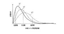
図3は、共鳴コイル(送電コイル13と受電コイル21)間の送電距離、受電コイル21及び電力取出コイル22間の結合強度、および無線電力装置の送電効率の関係を示す。図3における実線特性κ1は、受電コイル21及び電力取出コイル22が強結合状態にある時の送電効率特性を示す。破線特性κ2は、受電コイル21及び電力取出コイル22が中結合状態にある時の送電効率特性を示す。一点鎖線特性κ3は、受電コイル21及び電力取出コイル22が弱結合状態にある時の送電効率特性を示す。 FIG. 3 shows the relationship among the power transmission distance between the resonance coils (the
なお、「強結合状態」とは、例えば、送電コイル13と受電コイル21との結合強度κとエネルギー損失Gとの関係κ/Gが1よりも大きい場合を指す。「中結合状態」とは、例えばκ/Gが1の場合を指す。「弱結合状態」とは、例えばκ/Gが1未満の場合を指す。これらの結合状態の定義は一例である。また、図3における「共鳴コイル間の送電距離」は、送電コイル13と受電コイル21との結合強度の一例であり、送電距離の他に、送電コイル13及び受電コイル21の姿勢(角度)等も結合強度に影響を与える。また、「送電効率」とは、交流電源11からバッテリー24(負荷)までの電力消費分である。 The “strongly coupled state” refers to a case where the relationship κ / G between the coupling strength κ and the energy loss G between the
図3に示すように、送電コイル13と受電コイル21との送電距離が短い場合(送電コイル13と受電コイル21とが強結合状態にある場合)は、特性κ1に示すように受電コイル21と電力取出コイル22との結合を強める方が、システム全体の送電効率を高めることができる。すなわち、送電コイル13と受電コイル21とが強結合状態にある場合、送電コイル13から受電コイル21に多くの電力が送られる。この状態において、受電コイル21と電力取出コイル22とが弱結合状態になっていると、電力取出コイル22による受電コイル21からの電力の取出量が少なくなる。受電コイル21からの電力の取出量が少なくなると、受電コイル21における電力が高くなり、発熱による損失が生じることがある。そこで、本実施の形態では、送電コイル13と受電コイル21とが強結合状態になっている時は、受電コイル21と電力取出コイル22とを強結合状態にする。これにより、電力取出コイル22は受電コイル21からの電力の取出量を大きくすることができ、受電コイル21における発熱損失を抑えることができる。したがって、システム全体の送電効率を高めることができる。 As shown in FIG. 3, when the power transmission distance between the
一方、送電コイル13と受電コイル21との送電距離が長い場合(送電コイル13と受電コイル21とが弱結合状態にある場合)は、特性κ3に示すように受電コイル21と電力取出コイル22との結合を弱める方が、無線電力装置全体の送電効率を高めることができる。すなわち、送電コイル13と受電コイル21とが弱結合状態にある場合、送電コイル13から受電コイル21に送られる電力は小さくなる。この状態において、受電コイル21と電力取出コイル22とが強結合状態になっていると、受電コイル21に蓄積される電力が低くなりすぎる場合がある。よって、無線電力装置全体の送電効率は低下する。そこで本実施の形態では、送電コイル13と受電コイル21とが弱結合状態になっている時は、受電コイル21と電力取出コイル22とを弱結合状態にする。これにより、電力取出コイル22が受電コイル21から取り出そうとする電力は小さくなり、受電コイル21において電力が低下しすぎるのを防ぐことができる。したがって、無線電力装置全体の送電効率を高めることができる。 On the other hand, when the power transmission distance between the
以上のように、送電装置10と受電装置20との間で磁界共鳴方式を用いて送電を行う場合、送電コイル13と受電コイル21との結合強度(例えば距離)に応じて受電コイル21と電力取出コイル22との結合強度を変化させることが、無線電力装置全体の送電効率を向上できるため好ましい。なお、送電コイル13と受電コイル21との結合強度は、送電コイル13と受電コイル21との距離に限らず、送電装置10または受電装置20の設置姿勢や設置角度等によっても変化する。本実施の形態では、コイルの結合強度は距離によって変化することとして説明している。 As described above, when power transmission is performed between the
図4A〜図4Dは、受電コイルと電力取出コイルとの結合強度を変化させる具体例を示す。図4A〜図4Cは、受電コイルと電力取出コイルの断面図である。図4Dは、電力取出コイルの模式図である。図4A〜図4Cにおける受電コイル、および図4Aと図4Bに示す電力供給コイルは、実際は螺旋状に巻かれることもあるが、ここでは断面表記を簡略化している。 4A to 4D show specific examples in which the coupling strength between the power receiving coil and the power extraction coil is changed. 4A to 4C are cross-sectional views of the power reception coil and the power extraction coil. FIG. 4D is a schematic diagram of the power extraction coil. The power receiving coil in FIGS. 4A to 4C and the power supply coil shown in FIGS. 4A and 4B may be wound in a spiral shape, but here, the cross-sectional notation is simplified.
図4Aは、受電コイル21内に電力取出コイル22aを配置した構造である。電力取出コイル22aは、モータなどの駆動部により、図4Aに示す位置(実線表記した位置)から矢印Bに示す方向へ変位可能である。図4Aにおける破線円は、電力取出コイル22aが実線表記した位置から矢印Bに示す方向へ変位した時の位置の一例を示す。電力取出コイル22aを矢印Bに示す方向へ変位可能としたことにより、受電コイル21と電力取出コイル22aとの間隙を変化させることができる。受電コイル21と電力取出コイル22aとの間隙を変化させることにより、受電コイル21と電力取出コイル22aとの結合強度を変化させることができる。例えば、電力取出コイル22aが図4Aにおける実線位置にある時の受電コイル21と電力取出コイル22aとの結合強度をκ11とし、電力取出コイル22aが図4Aにおける破線円位置にある時の受電コイル21と電力取出コイル22aとの結合強度をκ12とした時、結合強度κ12は結合強度κ11よりも高い。 FIG. 4A shows a structure in which a
なお、図4Aに示す電力取出コイル22aは、受電コイル21に対する同軸位置(実線で示す位置)から破線円に示す位置までの間において、段階的または連続的に変位可能とすることができる。電力取出コイル22の位置を連続的に変位可能とすることで、受電コイル21と電力取出コイル22aとの結合強度を細かく設定することができる。また、電力取出コイル22aの変位方向は、矢印Bに示す方向に限らず、少なくとも受電コイル21と電力取出コイル22aとの間隙を変えることができる方向であればよい。電力取出コイル22aの変位方向は、受電コイル21の中心軸に略直交する方向であることが好ましい。 The
図4Bは、受電コイル21内に複数の電力取出コイル22b,22c,22dを配置した構造である。受電コイル21,電力取出コイル22b,22c,22dは、同軸位置に配されている。電力取出コイル22cは、電力取出コイル22b内に配されている。電力取出コイル22dは、電力取出コイル22c内に配されている。したがって、受電コイル21と電力取出コイル22bとの距離が最も短く、受電コイル21と電力取出コイル22dとの距離が最も長い。電力取出コイル22b〜22dには、それぞれスイッチ27aが接続されている。スイッチ27aは、電力取出コイル22b〜22dのうち少なくとも一つの電力取出コイルを通電状態にするように切り換えることができる。スイッチ27aの切り換え制御は、制御部26(図2参照)によって行われる。図4Bにおいて、電力取出コイル22dが通電状態にある時の受電コイル21と電力取出コイル22dとの結合強度をκ21とし、電力取出コイル22cが通電状態にある時の受電コイル21と電力取出コイル22cとの結合強度をκ22とし、電力取出コイル22bが通電状態にある時の受電コイル21と電力取出コイル22bとの結合強度をκ23とした時、結合強度は、
κ21<κ22<κ23
の関係にある。なお、図4Bに示す電力取出コイルは3個備えたが、少なくとも複数の電力取出コイルを同軸配置し、スイッチにより通電状態を切り換え可能な構成であればよい。FIG. 4B shows a structure in which a plurality of power extraction coils 22 b, 22 c, and 22 d are arranged in the
κ21 <κ22 <κ23
Are in a relationship. In addition, although the three power extraction coils shown in FIG. 4B are provided, any configuration is possible as long as at least a plurality of power extraction coils are arranged coaxially and the energization state can be switched by a switch.
図4Cは、受電コイル21内に断面形状が略矩形の電力取出コイル22eを備えている。電力取出コイル22eは、内側コイル部22fと外側コイル部22gとを備えている。内側コイル部22fと外側コイル部22gとは、一方の端部が電気的に接続されており、他方の端部がスイッチ27b及び27cにより接続/遮断可能である。内側コイル部22fは、外側コイル部22gの内側に配されている。スイッチ27b及び27cが端子a側に接続されることにより、内側コイル部22fが通電状態となる。内側コイル部22fが通電状態となることで、受電コイル21と電力取出コイル22eとの結合強度はκ31となる。スイッチ27b及び27cが端子b側に接続されることにより、外側コイル部22gが通電状態となる。外側コイル部22gが通電状態となることで、受電コイル21と電力取出コイル22eとの結合強度はκ32となる。結合強度κ32は、結合強度κ31よりも高い。なお、図4Cに示す電力取出コイル22eは、2つのコイル部(内側コイル部22f、外側コイル部22g)を備えているが、受電コイル21に対する結合強度が異なる3つ以上のコイル部を備え、スイッチ27b及び27cにより選択的に通電される構成としてもよい。 FIG. 4C includes a
図4Dは、螺旋状の電力取出コイル22hの端部にそれぞれ端子aと端子zとを備え、端子aと端子zとの間に端子bを備えている。端子aと端子bとは、スイッチ27dにより選択的に通電される。スイッチ27dが端子a側に接続されることで、電力取出コイル22hの全体を通電状態にすることができ、このときのインダクタンスはL1となる。スイッチ27dが端子b側に接続されることで、電力取出コイル22hの端子bから端子cまでの間の部分を通電状態にすることができ、このときのインダクタンスはL2となる。このように、スイッチ27dを切り換えることで電力取出コイル22hのインダクタンスを変化させることができるので、受電コイル21との結合強度を変化させることができる。受電コイル21の巻数、形状、配置関係は不変であるため、電力取出コイル22hのインダクタンスを変化させることで、受電コイル21と電力取出コイル22hとの結合強度を変化させることができる。 FIG. 4D includes a terminal a and a terminal z at each end of the spiral
図5Aは、制御部26の具体構成を示す。図5Aに示す制御部26は、図4Aに示す電力取出コイル22aを備えた受電装置20に搭載することができる。図5Aに示す制御部26は、電流検出回路26a、制御回路26b、モータドライバ26cを備えている。電流検出回路26aは、電流検出素子25から送られる電流波形に基づき電流振幅を測定する。電流振幅は、制御回路26bに送られる。制御回路26bは、電流検出回路26aから送られる電流振幅を蓄積し、今回測定された電流振幅と前回測定された電流振幅とを比較する。制御回路26bは、電流振幅の比較の結果、電力取出コイル22を変位させる必要があると判断した場合は、モータドライバ26cに制御信号を送る。モータドライバ26cは、制御回路26bから送られる制御信号に基づき、モータ28にモータ駆動電流を送る。モータ28は、モータドライバ26cから送られるモータ駆動電流により動作し、電力取出コイル22aを矢印Bまたはに示す方向へ変位させる。 FIG. 5A shows a specific configuration of the
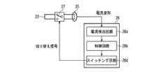
図5Bは、制御部26の具体構成を示す。図5Bに示す制御部26は、図4B〜図4Dに示す電力取出コイルを備えた受電装置20に搭載することができる。図5Bに示す制御部26は、電流検出回路26a、制御回路26b、スイッチング回路26dを備えている。電流検出回路26aは、電流検出素子25から送られる電流波形に基づき電流振幅を測定する。電流振幅は、制御回路26bに送られる。制御回路26bは、電流検出回路26aから送られる電流振幅を蓄積し、今回測定された電流振幅と前回測定された電流振幅とを比較する。制御回路26bは、電流振幅の比較の結果、電力取出コイル22を変位させる必要があると判断した場合は、スイッチング回路26dに制御信号を送る。スイッチング回路26dは、制御回路26bから送られる制御信号に基づき、スイッチ27を切り換え制御する。 FIG. 5B shows a specific configuration of the
〔2.無線電力装置の動作〕
図2に示す無線電力装置において、交流電源11から出力される電流は電力供給コイル12に入力される。電力供給コイル12は、電流が入力されることにより電磁界を発生させ、電磁エネルギーを用いて送電コイル13に電力を供給する。送電コイル13に電力を供給することにより、送電コイル13と受電コイル21との間に磁界が発生する。送電コイル13と受電コイル21とは、同じ共振周波数を有するため、両者の間に磁界共鳴が生じる。これにより、送電コイル13から受電コイル21へ電力を供給することができる。[2. Operation of wireless power device
In the wireless power device shown in FIG. 2, the current output from the
電力取出コイル22は、電磁誘導により受電コイル21から電力を取り出すことができる。電力取出コイル22によって取り出された電力は、整流回路23を介して、バッテリー24等の負荷へ供給される。 The
ここで、送電装置10と受電装置20とは、離間しているため、互いの相対位置が変動することがある。送電装置10と受電装置20との相対位置が変動し、送電コイル13と受電コイル21との結合強度が変動すると、図2に示すように無線電力装置全体の送電効率も変動する。 Here, since the
例えば、受電コイル21と電力取出コイル22とが中結合状態の時に、送電コイル13と受電コイル21との結合強度が中結合状態(図2における中距離に相当)から強結合状態に変化した場合(図2における近距離に相当)、送電効率が大幅に低下する。これは、電力取出コイル22により受電コイル21から取り出される電力よりも、受電コイル21に蓄積される電力の方が大きくなることにより、受電コイル21において発熱損失が生じるからである。一方、送電コイル13と受電コイル21との結合強度が中結合状態から弱結合状態に変化した場合(図2における遠距離に相当)も、送電効率が大幅に低下する。これは、受電コイル21に蓄積される電力よりも、電力取出コイル22により受電コイル21から取り出される電力の方が大きくなることにより、受電コイル21における電力が低下するからである。このように、受電コイル21と電力取出コイル22との結合強度が一定であると、送電コイル13と受電コイル21との結合強度が変動した際に、無線電力装置全体の送電効率が低下することがある。 For example, when the
そこで本実施の形態では、電力取出コイル22に流れる電流を検出して、その電流振幅に応じて受電コイル21と電力取出コイル22との結合強度を変化させている。すなわち、送電コイル13と受電コイル21との結合強度に応じて、受電コイル21と電力取出コイル22との結合強度を変化させている。 Therefore, in the present embodiment, the current flowing through the
図6は、無線電力装置の制御フローを示す。なお、制御部26は、図5A及び図5Bのうちいずれの構成であってもよいが、以下の説明では図5Aに示す制御部26を受電装置20に備えていることとしている。 FIG. 6 shows a control flow of the wireless power apparatus. Note that the
まず、送電装置10から受電装置20へ電力を供給する前に、制御部26は、モータ28にモータ駆動電流を送り、電力取出コイル22が初期位置に位置するよう制御する。電力取出コイル22の初期位置は、例えば図4Aにおける実線位置とする(S1)。 First, before supplying power from the
次に、送電装置10から受電装置20へ電力を供給する。具体的な電力供給動作は、前述したので省略する。受電コイル21に供給された電力は、電磁誘導により電力取出コイル22に供給される。電力取出コイル22に供給された電力は、整流回路24を介してバッテリー25に供給される(S2)。 Next, power is supplied from the
次に、電流検出素子25は、電力取出コイル22に流れる電流を検出し、電流波形を電流検出回路26aに送る。電流検出回路26aは、電流検出素子25から送られる電流波形に基づき、電流の振幅を測定する。電流検出回路26aは、測定した振幅を制御回路26bに送る(S3)。 Next, the
次に、制御回路26bは、電流検出回路26aで実行された電流測定の回数をカウントする(S4)。制御回路26bは、もし今回の電流測定が1回目である場合(S4におけるNO判断)は、測定された振幅を記憶し(S8)、モータドライバ26cに制御信号を出力する。モータドライバ26cは、制御回路26bから送られる制御信号に基づき、モータ28にモータ駆動電流を送る。モータ28は、モータドライバ26cから送られるモータ駆動電流に基づき駆動し、電力取出コイル22(具体構成は、図4Aに示す電力取出コイル22a)を矢印Bに示す方向へ変位させる。これにより、受電コイル21と電力取出コイル22との結合強度が高くなる。なお、電力取出コイル22の変位量は、制御回路26bにおいて電流振幅と変位量とをテーブル化して持っておくことが好ましい。 Next, the
次に、電流検出回路26aは、再度電流検出素子25から電流波形を取得し、電流振幅を制御回路26bに出力する(S3)。 Next, the
次に、制御回路26bは、電流検出回路26aで実行された電流測定の回数が2回目であると判断し(S4におけるYES判断)、今回測定した電流振幅と前回測定した電流振幅とを比較する(S5)。制御回路26bは、今回測定した電流振幅が前回測定した電流振幅よりも大きくなったと判断した場合は(S5におけるNO判断)、今回測定した電流振幅を記憶し(S8)、以降上記と同様の処理を実行する。一方、制御回路26bは、今回測定した電流振幅が前回測定した電流振幅よりも小さくなったと判断した場合は(S5におけるYES判断)、電力取出コイル22を直前の状態に戻す制御を行う。具体的には、S9において矢印Bに示す方向へ変位させた電力取出コイル22を、元の位置に戻す制御を行う(S6)。すなわち、送電コイル13と受電コイル21との結合強度が高くなると電力取出コイル22に流れる電流の振幅が大きくなるため(S5におけるNO判断)、その場合は受電コイル21と電力取出コイル22との結合強度を高くする。また、送電コイル13と受電コイル21との結合強度が低くなると電流取出コイル22に流れる電流の振幅が小さくなるため(S5におけるYES判断)、受電コイル21と電力取出コイル22との結合強度を低くする。 Next, the
以上により電力取出コイル22の最適位置を決定することができる(S7)。これにより、送電コイル13と受電コイル21との結合強度に適した、受電コイル21と電力取出コイル22との結合強度に設定して、電力を負荷へ供給することができる。 Thus, the optimum position of the
〔3.実施の形態の効果、他〕
実施の形態にかかる無線電力装置は、送電コイル13と受電コイル21との結合状態に応じて、受電コイル21と電力取出コイル22との結合状態を変化させている。すなわち、送電コイル13と受電コイル21とが強結合状態の場合は、受電コイル21と電力取出コイル22とを強結合状態にし、送電コイル13と受電コイル21とが弱結合状態の場合は、受電コイル21と電力取出コイル22とを弱結合状態にする。このような構成とすることにより、受電コイル21から電力取出コイル22に供給される電力の過剰な低下や、受電コイル21における発熱損失を抑えることができる。したがって、無線電力装置全体の送電効率を最適化することができる。[3. Effects of the embodiment, etc.]
The wireless power device according to the embodiment changes the coupling state between the
なお、本実施の形態にかかる無線電力装置は、携帯電話端末やデジタルカメラなど充電池により駆動する機器の充電装置に有用である。また、充電装置に限らず、送電装置と、送電装置から供給される電力を消費しながら駆動する受電装置とを備えたシステムにも有用である。すなわち、受電装置に充電機能を備えていないシステムにも有用である。 Note that the wireless power device according to the present embodiment is useful for a charging device of a device driven by a rechargeable battery such as a mobile phone terminal or a digital camera. Further, the present invention is not limited to the charging device, and is also useful for a system including a power transmission device and a power reception device that is driven while consuming electric power supplied from the power transmission device. That is, it is also useful for a system in which the power receiving device does not have a charging function.
また、図4A〜図4Dは、受電コイル21と電力取出コイル22との結合状態を可変する構造の例であり、少なくとも受電コイル21と電力取出コイル22との結合状態を可変できればこれらの構造に限らない。例えば、電力取出コイル22に可変インダクタンスを設けて、電力取出コイル22の共振周波数を変更可能にする構成としてもよい。 4A to 4D are examples of structures in which the coupling state between the
また、本実施の形態における送電コイル13は、本発明の送電コイルの一例である。本実施の形態における受電コイル21は、本発明の受電コイルの一例である。本実施の形態における電力取出コイル22,22a,22b,22c,22d,22eは、本発明の電力取出コイルの一例である。本実施の形態における電流検出素子25は、本発明の検出部の一例である。本実施の形態における制御部26は、本発明の制御部の一例である。本実施の形態におけるモータ28は、本発明の駆動部の一例である。本実施の形態におけるスイッチ27は、本発明の切換部の一例である。 Moreover, the
本発明は、送信装置から受信装置へ無線で電力を供給できる無線電力装置に有用である。 The present invention is useful for a wireless power apparatus that can wirelessly supply power from a transmission apparatus to a reception apparatus.
10 送電装置
11 交流電源
12 電力供給コイル
13 送電コイル
20 受電装置
21 受電コイル
22 電力取出コイル
25 電流検出素子
26 制御部
27 スイッチ
28 モータDESCRIPTION OF
Claims (8)
Translated fromJapanese前記受電コイルから電磁誘導で電力を取り出す電力取出コイルとを備えた、無線電力装置であって、
前記電力取出コイルに流れる電流を検出する検出部と、
前記検出部で検出した電流に基づき、前記電力取出コイルと前記受電コイルとの結合強度を制御する制御部とを備えた、無線電力装置。A power receiving coil that receives electric power as magnetic field energy from the power transmission coil using magnetic field resonance generated between the power transmission coil and
A wireless power device comprising a power extraction coil for extracting power from the power receiving coil by electromagnetic induction,
A detection unit for detecting a current flowing in the power extraction coil;
A wireless power apparatus comprising: a control unit that controls a coupling strength between the power extraction coil and the power receiving coil based on a current detected by the detection unit.
前記電力取出コイルに流れる電流が大きくなると、前記電力取出コイルと前記受電コイルとの結合強度を高くし、前記電力取出コイルに流れる電流が小さくなると、前記電力取出コイルと前記受電コイルとの結合強度を低くするよう制御する、請求項1記載の無線電力装置。The controller is
Binding of the current flowing through the power extraction coil is increased, to increase the bond strength between the receiving coil and the power take-out coil, the current flowing through thepower extraction coil is reduced, and the power receiving coil and the power take-out coil The wireless power device according to claim 1, wherein the wireless power device is controlled so as to reduce the strength.
前記制御部は、前記検出部で検出した電流に基づき、前記電力取出コイルを変位させるよう前記駆動部を制御する、請求項1または2記載の無線電力装置。A drive unit capable of displacing the power extraction coil so as to change the coupling strength between the power reception coil and the power extraction coil;
The wireless power device according to claim 1, wherein the control unit controls the drive unit to displace the power extraction coil based on the current detected by the detection unit.
前記受電コイルに対する結合強度がそれぞれ異なる複数のコイルと、
前記複数のコイルのうち少なくとも一つを選択可能な切換部とを備え、
前記制御部は、前記検出部で検出した電流に基づき、前記切換部を切り換え制御する、請求項1または2記載の無線電力装置。The power extraction coil is
A plurality of coils having different coupling strengths to the power receiving coil, and
A switching unit capable of selecting at least one of the plurality of coils,
The wireless power device according to claim 1, wherein the control unit switches and controls the switching unit based on a current detected by the detection unit.
前記受電コイルから電力取出コイルへ電磁誘導で電力を取り出す、無線電力受信方法であって、
前記電力取出コイルに流れる電流を検出し、
前記検出した電流の振幅に基づき、前記電力取出コイルと前記受電コイルとの結合強度を制御する、無線電力受信方法。Using magnetic field resonance that occurs between the power transmission coil and the power reception coil, power is supplied from the power transmission coil to the power reception coil as magnetic field energy,
A wireless power receiving method for extracting power from the power receiving coil to a power extracting coil by electromagnetic induction,
Detecting the current flowing in the power extraction coil;
Based on the amplitude of priordangerous out current controls the coupling strength between the power receiving coil and the power take-out coil, the wireless power receiving method.
前記電力取出コイルに流れる電流が小さくなると、前記電力取出コイルと前記受電コイルとの結合強度を低くする、請求項5記載の無線電力受信方法。When the current flowing through the power extraction coil increases, the coupling strength between the power extraction coil and the power reception coil is increased,
When the current flowing through thepower extraction coil is reduced, lowering the bond strength between the receiving coil and the power take-out coil, the wireless power receiving method according to claim 5, wherein.
Priority Applications (2)
| Application Number | Priority Date | Filing Date | Title |
|---|---|---|---|
| JP2009085281AJP5353376B2 (en) | 2009-03-31 | 2009-03-31 | Wireless power device and wireless power receiving method |
| US12/750,774US8482159B2 (en) | 2009-03-31 | 2010-03-31 | Wireless power apparatus and wireless power-receiving method |
Applications Claiming Priority (1)
| Application Number | Priority Date | Filing Date | Title |
|---|---|---|---|
| JP2009085281AJP5353376B2 (en) | 2009-03-31 | 2009-03-31 | Wireless power device and wireless power receiving method |
Publications (2)
| Publication Number | Publication Date |
|---|---|
| JP2010239777A JP2010239777A (en) | 2010-10-21 |
| JP5353376B2true JP5353376B2 (en) | 2013-11-27 |
Family
ID=42783247
Family Applications (1)
| Application Number | Title | Priority Date | Filing Date |
|---|---|---|---|
| JP2009085281AExpired - Fee RelatedJP5353376B2 (en) | 2009-03-31 | 2009-03-31 | Wireless power device and wireless power receiving method |
Country Status (2)
| Country | Link |
|---|---|
| US (1) | US8482159B2 (en) |
| JP (1) | JP5353376B2 (en) |
Families Citing this family (143)
| Publication number | Priority date | Publication date | Assignee | Title |
|---|---|---|---|---|
| US7825543B2 (en) | 2005-07-12 | 2010-11-02 | Massachusetts Institute Of Technology | Wireless energy transfer |
| US9421388B2 (en) | 2007-06-01 | 2016-08-23 | Witricity Corporation | Power generation for implantable devices |
| US8115448B2 (en) | 2007-06-01 | 2012-02-14 | Michael Sasha John | Systems and methods for wireless power |
| CN102099958B (en) | 2008-05-14 | 2013-12-25 | 麻省理工学院 | Wireless power transfer including interference enhancement |
| US8933594B2 (en) | 2008-09-27 | 2015-01-13 | Witricity Corporation | Wireless energy transfer for vehicles |
| US9035499B2 (en) | 2008-09-27 | 2015-05-19 | Witricity Corporation | Wireless energy transfer for photovoltaic panels |
| US8461720B2 (en) | 2008-09-27 | 2013-06-11 | Witricity Corporation | Wireless energy transfer using conducting surfaces to shape fields and reduce loss |
| US8907531B2 (en) | 2008-09-27 | 2014-12-09 | Witricity Corporation | Wireless energy transfer with variable size resonators for medical applications |
| US9544683B2 (en) | 2008-09-27 | 2017-01-10 | Witricity Corporation | Wirelessly powered audio devices |
| US8587153B2 (en) | 2008-09-27 | 2013-11-19 | Witricity Corporation | Wireless energy transfer using high Q resonators for lighting applications |
| US9093853B2 (en) | 2008-09-27 | 2015-07-28 | Witricity Corporation | Flexible resonator attachment |
| US8686598B2 (en) | 2008-09-27 | 2014-04-01 | Witricity Corporation | Wireless energy transfer for supplying power and heat to a device |
| US9184595B2 (en) | 2008-09-27 | 2015-11-10 | Witricity Corporation | Wireless energy transfer in lossy environments |
| US8569914B2 (en) | 2008-09-27 | 2013-10-29 | Witricity Corporation | Wireless energy transfer using object positioning for improved k |
| US8497601B2 (en) | 2008-09-27 | 2013-07-30 | Witricity Corporation | Wireless energy transfer converters |
| US8957549B2 (en) | 2008-09-27 | 2015-02-17 | Witricity Corporation | Tunable wireless energy transfer for in-vehicle applications |
| US8912687B2 (en) | 2008-09-27 | 2014-12-16 | Witricity Corporation | Secure wireless energy transfer for vehicle applications |
| US9744858B2 (en) | 2008-09-27 | 2017-08-29 | Witricity Corporation | System for wireless energy distribution in a vehicle |
| US8552592B2 (en) | 2008-09-27 | 2013-10-08 | Witricity Corporation | Wireless energy transfer with feedback control for lighting applications |
| US9105959B2 (en) | 2008-09-27 | 2015-08-11 | Witricity Corporation | Resonator enclosure |
| US8643326B2 (en) | 2008-09-27 | 2014-02-04 | Witricity Corporation | Tunable wireless energy transfer systems |
| US8324759B2 (en) | 2008-09-27 | 2012-12-04 | Witricity Corporation | Wireless energy transfer using magnetic materials to shape field and reduce loss |
| US8400017B2 (en) | 2008-09-27 | 2013-03-19 | Witricity Corporation | Wireless energy transfer for computer peripheral applications |
| US9601261B2 (en) | 2008-09-27 | 2017-03-21 | Witricity Corporation | Wireless energy transfer using repeater resonators |
| US8772973B2 (en) | 2008-09-27 | 2014-07-08 | Witricity Corporation | Integrated resonator-shield structures |
| US8487480B1 (en) | 2008-09-27 | 2013-07-16 | Witricity Corporation | Wireless energy transfer resonator kit |
| US8901779B2 (en) | 2008-09-27 | 2014-12-02 | Witricity Corporation | Wireless energy transfer with resonator arrays for medical applications |
| US8947186B2 (en) | 2008-09-27 | 2015-02-03 | Witricity Corporation | Wireless energy transfer resonator thermal management |
| US8476788B2 (en) | 2008-09-27 | 2013-07-02 | Witricity Corporation | Wireless energy transfer with high-Q resonators using field shaping to improve K |
| US9601270B2 (en) | 2008-09-27 | 2017-03-21 | Witricity Corporation | Low AC resistance conductor designs |
| US9396867B2 (en) | 2008-09-27 | 2016-07-19 | Witricity Corporation | Integrated resonator-shield structures |
| US8937408B2 (en) | 2008-09-27 | 2015-01-20 | Witricity Corporation | Wireless energy transfer for medical applications |
| US8304935B2 (en) | 2008-09-27 | 2012-11-06 | Witricity Corporation | Wireless energy transfer using field shaping to reduce loss |
| US8629578B2 (en) | 2008-09-27 | 2014-01-14 | Witricity Corporation | Wireless energy transfer systems |
| US8461722B2 (en) | 2008-09-27 | 2013-06-11 | Witricity Corporation | Wireless energy transfer using conducting surfaces to shape field and improve K |
| US9515494B2 (en) | 2008-09-27 | 2016-12-06 | Witricity Corporation | Wireless power system including impedance matching network |
| US9065423B2 (en) | 2008-09-27 | 2015-06-23 | Witricity Corporation | Wireless energy distribution system |
| US8723366B2 (en) | 2008-09-27 | 2014-05-13 | Witricity Corporation | Wireless energy transfer resonator enclosures |
| US9601266B2 (en) | 2008-09-27 | 2017-03-21 | Witricity Corporation | Multiple connected resonators with a single electronic circuit |
| US8692412B2 (en) | 2008-09-27 | 2014-04-08 | Witricity Corporation | Temperature compensation in a wireless transfer system |
| US8901778B2 (en) | 2008-09-27 | 2014-12-02 | Witricity Corporation | Wireless energy transfer with variable size resonators for implanted medical devices |
| US8922066B2 (en) | 2008-09-27 | 2014-12-30 | Witricity Corporation | Wireless energy transfer with multi resonator arrays for vehicle applications |
| EP3179640A1 (en) | 2008-09-27 | 2017-06-14 | WiTricity Corporation | Wireless energy transfer systems |
| US9106203B2 (en) | 2008-09-27 | 2015-08-11 | Witricity Corporation | Secure wireless energy transfer in medical applications |
| US8928276B2 (en) | 2008-09-27 | 2015-01-06 | Witricity Corporation | Integrated repeaters for cell phone applications |
| US8692410B2 (en) | 2008-09-27 | 2014-04-08 | Witricity Corporation | Wireless energy transfer with frequency hopping |
| US8466583B2 (en) | 2008-09-27 | 2013-06-18 | Witricity Corporation | Tunable wireless energy transfer for outdoor lighting applications |
| US9318922B2 (en) | 2008-09-27 | 2016-04-19 | Witricity Corporation | Mechanically removable wireless power vehicle seat assembly |
| US8598743B2 (en) | 2008-09-27 | 2013-12-03 | Witricity Corporation | Resonator arrays for wireless energy transfer |
| US8471410B2 (en) | 2008-09-27 | 2013-06-25 | Witricity Corporation | Wireless energy transfer over distance using field shaping to improve the coupling factor |
| US9160203B2 (en) | 2008-09-27 | 2015-10-13 | Witricity Corporation | Wireless powered television |
| US8461721B2 (en) | 2008-09-27 | 2013-06-11 | Witricity Corporation | Wireless energy transfer using object positioning for low loss |
| US9246336B2 (en) | 2008-09-27 | 2016-01-26 | Witricity Corporation | Resonator optimizations for wireless energy transfer |
| US8946938B2 (en) | 2008-09-27 | 2015-02-03 | Witricity Corporation | Safety systems for wireless energy transfer in vehicle applications |
| US8482158B2 (en) | 2008-09-27 | 2013-07-09 | Witricity Corporation | Wireless energy transfer using variable size resonators and system monitoring |
| US8410636B2 (en) | 2008-09-27 | 2013-04-02 | Witricity Corporation | Low AC resistance conductor designs |
| US8963488B2 (en) | 2008-09-27 | 2015-02-24 | Witricity Corporation | Position insensitive wireless charging |
| US8441154B2 (en) | 2008-09-27 | 2013-05-14 | Witricity Corporation | Multi-resonator wireless energy transfer for exterior lighting |
| US9577436B2 (en) | 2008-09-27 | 2017-02-21 | Witricity Corporation | Wireless energy transfer for implantable devices |
| US8587155B2 (en) | 2008-09-27 | 2013-11-19 | Witricity Corporation | Wireless energy transfer using repeater resonators |
| US8669676B2 (en) | 2008-09-27 | 2014-03-11 | Witricity Corporation | Wireless energy transfer across variable distances using field shaping with magnetic materials to improve the coupling factor |
| US8362651B2 (en) | 2008-10-01 | 2013-01-29 | Massachusetts Institute Of Technology | Efficient near-field wireless energy transfer using adiabatic system variations |
| JP4915438B2 (en)* | 2009-07-24 | 2012-04-11 | Tdk株式会社 | Wireless power supply apparatus and wireless power transmission system |
| WO2011062827A2 (en) | 2009-11-17 | 2011-05-26 | Apple Inc. | Wireless power utilization in a local computing environment |
| KR20110102758A (en)* | 2010-03-11 | 2011-09-19 | 삼성전자주식회사 | 3D glasses, charging cradles, 3D display devices and 3D glasses wireless charging system |
| EP2367263B1 (en) | 2010-03-19 | 2019-05-01 | TDK Corporation | Wireless power feeder, wireless power receiver, and wireless power transmission system |
| JP5664015B2 (en)* | 2010-08-23 | 2015-02-04 | Tdk株式会社 | Coil device and non-contact power transmission device |
| US9602168B2 (en) | 2010-08-31 | 2017-03-21 | Witricity Corporation | Communication in wireless energy transfer systems |
| GB2485616A (en)* | 2010-11-22 | 2012-05-23 | Bombardier Transp Gmbh | Route for transferring electric energy to vehicles |
| AU2011332142B2 (en)* | 2010-11-23 | 2014-12-11 | Apple Inc. | Wireless power utilization in a local computing environment |
| WO2012071088A1 (en)* | 2010-11-24 | 2012-05-31 | University Of Florida Research Foundation Inc. | Wireless power transfer via electrodynamic coupling |
| WO2012086625A1 (en)* | 2010-12-21 | 2012-06-28 | 矢崎総業株式会社 | Power feed system |
| US8800738B2 (en) | 2010-12-28 | 2014-08-12 | Tdk Corporation | Wireless power feeder and wireless power receiver |
| US8664803B2 (en)* | 2010-12-28 | 2014-03-04 | Tdk Corporation | Wireless power feeder, wireless power receiver, and wireless power transmission system |
| US8723368B2 (en)* | 2010-12-29 | 2014-05-13 | National Semiconductor Corporation | Electrically tunable inductor |
| JP2012165527A (en) | 2011-02-04 | 2012-08-30 | Nitto Denko Corp | Wireless power supply system |
| US9035500B2 (en) | 2011-03-01 | 2015-05-19 | Tdk Corporation | Wireless power feeder, wireless power receiver, and wireless power transmission system, and coil |
| US8922064B2 (en) | 2011-03-01 | 2014-12-30 | Tdk Corporation | Wireless power feeder, wireless power receiver, and wireless power transmission system, and coil |
| US8742627B2 (en) | 2011-03-01 | 2014-06-03 | Tdk Corporation | Wireless power feeder |
| KR101188808B1 (en) | 2011-03-03 | 2012-10-09 | (주)엠에이피테크 | Wireless charging apparatus for mobile |
| WO2012124029A1 (en)* | 2011-03-11 | 2012-09-20 | トヨタ自動車株式会社 | Coil unit, power transmission device, external power supply device, and vehicle charging system |
| KR101246693B1 (en)* | 2011-03-23 | 2013-03-21 | 주식회사 한림포스텍 | Wireless power receiving device and power control method thereof |
| US10685780B2 (en) | 2011-03-29 | 2020-06-16 | Sony Corporation | Electric power feed apparatus, electric power feed system, and electronic apparatus |
| US8772976B2 (en) | 2011-03-30 | 2014-07-08 | Intel Corporation | Reconfigurable coil techniques |
| US9496081B2 (en)* | 2011-04-08 | 2016-11-15 | Access Business Group International Llc | Counter wound inductive power supply |
| JP5968596B2 (en) | 2011-04-11 | 2016-08-10 | 日東電工株式会社 | Wireless power supply system |
| JP2012244763A (en)* | 2011-05-19 | 2012-12-10 | Sony Corp | Power supply device, power supply system and electronic device |
| CN103582990B (en) | 2011-05-31 | 2016-03-16 | 苹果公司 | Multiple resonance coils of the one-tenth tight spacing array of magnetic decoupling |
| JP5071574B1 (en)* | 2011-07-05 | 2012-11-14 | ソニー株式会社 | Sensing device, power receiving device, non-contact power transmission system, and sensing method |
| US9948145B2 (en) | 2011-07-08 | 2018-04-17 | Witricity Corporation | Wireless power transfer for a seat-vest-helmet system |
| CN108110907B (en) | 2011-08-04 | 2022-08-02 | 韦特里西提公司 | Tunable wireless power supply architecture |
| EP2754222B1 (en) | 2011-09-09 | 2015-11-18 | Witricity Corporation | Foreign object detection in wireless energy transfer systems |
| US20130062966A1 (en) | 2011-09-12 | 2013-03-14 | Witricity Corporation | Reconfigurable control architectures and algorithms for electric vehicle wireless energy transfer systems |
| KR20130033867A (en)* | 2011-09-27 | 2013-04-04 | 삼성전기주식회사 | Wireless power transmission system |
| US9318257B2 (en) | 2011-10-18 | 2016-04-19 | Witricity Corporation | Wireless energy transfer for packaging |
| CA2853824A1 (en) | 2011-11-04 | 2013-05-10 | Witricity Corporation | Wireless energy transfer modeling tool |
| JP2015508987A (en) | 2012-01-26 | 2015-03-23 | ワイトリシティ コーポレーションWitricity Corporation | Wireless energy transmission with reduced field |
| US8933589B2 (en) | 2012-02-07 | 2015-01-13 | The Gillette Company | Wireless power transfer using separately tunable resonators |
| JP6095957B2 (en) | 2012-04-17 | 2017-03-15 | 日東電工株式会社 | Wireless power transmission device, power feeding device, and power receiving device |
| KR101844422B1 (en) | 2012-04-19 | 2018-04-03 | 삼성전자주식회사 | Apparatus and method for wireless energy transmission and apparatus wireless energy reception |
| US9343922B2 (en) | 2012-06-27 | 2016-05-17 | Witricity Corporation | Wireless energy transfer for rechargeable batteries |
| US9287607B2 (en) | 2012-07-31 | 2016-03-15 | Witricity Corporation | Resonator fine tuning |
| US9595378B2 (en) | 2012-09-19 | 2017-03-14 | Witricity Corporation | Resonator enclosure |
| EP2909912B1 (en) | 2012-10-19 | 2022-08-10 | WiTricity Corporation | Foreign object detection in wireless energy transfer systems |
| US9842684B2 (en) | 2012-11-16 | 2017-12-12 | Witricity Corporation | Systems and methods for wireless power system with improved performance and/or ease of use |
| JP5716725B2 (en) | 2012-11-21 | 2015-05-13 | トヨタ自動車株式会社 | Power transmission device and power transmission system |
| CN103036319A (en)* | 2012-12-10 | 2013-04-10 | 苏州金纳信息技术有限公司 | High-efficient power line electricity taking achieving device |
| KR101991341B1 (en)* | 2013-01-04 | 2019-06-20 | 삼성전자 주식회사 | Wireless power reception device and wireless power transmission system |
| JP6282398B2 (en)* | 2013-02-19 | 2018-02-21 | 矢崎総業株式会社 | Electromagnetic induction coil |
| JP2014204452A (en) | 2013-04-01 | 2014-10-27 | 日東電工株式会社 | Power reception apparatus |
| JP6103527B2 (en) | 2013-04-17 | 2017-03-29 | 矢崎総業株式会社 | Surplus length absorber and coil unit |
| US9352661B2 (en) | 2013-04-29 | 2016-05-31 | Qualcomm Incorporated | Induction power transfer system with coupling and reactance selection |
| CN104143861A (en)* | 2013-05-09 | 2014-11-12 | 泰科电子(上海)有限公司 | Contactless power supply circuit |
| JP5616496B1 (en) | 2013-07-08 | 2014-10-29 | 日東電工株式会社 | Power supply / reception device and portable device |
| KR102125917B1 (en)* | 2013-08-07 | 2020-07-08 | 엘지이노텍 주식회사 | Wireless power transmitting device |
| US9857821B2 (en) | 2013-08-14 | 2018-01-02 | Witricity Corporation | Wireless power transfer frequency adjustment |
| US9780573B2 (en) | 2014-02-03 | 2017-10-03 | Witricity Corporation | Wirelessly charged battery system |
| US9952266B2 (en) | 2014-02-14 | 2018-04-24 | Witricity Corporation | Object detection for wireless energy transfer systems |
| US9842687B2 (en) | 2014-04-17 | 2017-12-12 | Witricity Corporation | Wireless power transfer systems with shaped magnetic components |
| US9892849B2 (en) | 2014-04-17 | 2018-02-13 | Witricity Corporation | Wireless power transfer systems with shield openings |
| US9837860B2 (en) | 2014-05-05 | 2017-12-05 | Witricity Corporation | Wireless power transmission systems for elevators |
| JP2017518018A (en) | 2014-05-07 | 2017-06-29 | ワイトリシティ コーポレーションWitricity Corporation | Foreign object detection in wireless energy transmission systems |
| US9954375B2 (en) | 2014-06-20 | 2018-04-24 | Witricity Corporation | Wireless power transfer systems for surfaces |
| US10574091B2 (en) | 2014-07-08 | 2020-02-25 | Witricity Corporation | Enclosures for high power wireless power transfer systems |
| CN107258046B (en) | 2014-07-08 | 2020-07-17 | 无线电力公司 | Resonator equalization in wireless power transfer systems |
| US9843217B2 (en) | 2015-01-05 | 2017-12-12 | Witricity Corporation | Wireless energy transfer for wearables |
| JP2016225577A (en)* | 2015-06-03 | 2016-12-28 | 船井電機株式会社 | Power supply device and power reception device |
| KR20170024406A (en) | 2015-08-25 | 2017-03-07 | 삼성전자주식회사 | Electronic device and method for controlling temperature of the electronic device |
| US10248899B2 (en) | 2015-10-06 | 2019-04-02 | Witricity Corporation | RFID tag and transponder detection in wireless energy transfer systems |
| US9929721B2 (en) | 2015-10-14 | 2018-03-27 | Witricity Corporation | Phase and amplitude detection in wireless energy transfer systems |
| WO2017070227A1 (en) | 2015-10-19 | 2017-04-27 | Witricity Corporation | Foreign object detection in wireless energy transfer systems |
| WO2017070009A1 (en) | 2015-10-22 | 2017-04-27 | Witricity Corporation | Dynamic tuning in wireless energy transfer systems |
| US10075019B2 (en) | 2015-11-20 | 2018-09-11 | Witricity Corporation | Voltage source isolation in wireless power transfer systems |
| WO2017136491A1 (en) | 2016-02-02 | 2017-08-10 | Witricity Corporation | Controlling wireless power transfer systems |
| CN114123540B (en) | 2016-02-08 | 2024-08-20 | 韦特里西提公司 | Variable capacitance device and high-power wireless energy transmission system |
| KR102572577B1 (en) | 2016-04-15 | 2023-08-30 | 삼성전자주식회사 | Charging apparatus and method for controlling wireless charging |
| JP6855878B2 (en) | 2017-03-29 | 2021-04-07 | 富士通株式会社 | Power receiver, power transmission system, and power receiver control method |
| KR102268987B1 (en)* | 2017-04-07 | 2021-06-24 | 광동 오포 모바일 텔레커뮤니케이션즈 코포레이션 리미티드 | Wireless charging device, wireless charging method and charging standby equipment |
| US10421368B2 (en)* | 2017-04-26 | 2019-09-24 | Witricity Corporation | Static power derating for dynamic charging |
| WO2019006376A1 (en) | 2017-06-29 | 2019-01-03 | Witricity Corporation | Protection and control of wireless power systems |
| US10951064B2 (en)* | 2018-02-28 | 2021-03-16 | Massachusetts Institute Of Technology | Coreless power transformer |
| JP2023011425A (en)* | 2021-07-12 | 2023-01-24 | 伊藤忠Tc建機株式会社 | construction elevator |
| US12413104B1 (en)* | 2024-05-05 | 2025-09-09 | Microchip Technology Incorporated | Power loss accounting method for in-power foreign object detection |
Family Cites Families (23)
| Publication number | Priority date | Publication date | Assignee | Title |
|---|---|---|---|---|
| US2967267A (en)* | 1958-03-26 | 1961-01-03 | Litton Systems Inc | Reactive intercoupling of modular units |
| GB2262634B (en)* | 1991-12-18 | 1995-07-12 | Apple Computer | Power connection scheme |
| EP0788212B1 (en)* | 1996-01-30 | 2002-04-17 | Sumitomo Wiring Systems, Ltd. | Connection system and connection method for an electric automotive vehicle |
| JP4200257B2 (en) | 2000-09-26 | 2008-12-24 | パナソニック電工株式会社 | Non-contact power transmission device |
| JP2003168088A (en)* | 2001-11-29 | 2003-06-13 | Matsushita Electric Ind Co Ltd | Non-contact IC card |
| KR20040072581A (en)* | 2004-07-29 | 2004-08-18 | (주)제이씨 프로텍 | An amplification relay device of electromagnetic wave and a radio electric power conversion apparatus using the above device |
| KR200367018Y1 (en)* | 2004-08-13 | 2004-11-09 | 안재혁 | A Control Circuit for AC Voltage |
| DE102005022352A1 (en)* | 2005-05-13 | 2006-11-23 | BSH Bosch und Siemens Hausgeräte GmbH | Energy transmission device |
| CN101860089B (en) | 2005-07-12 | 2013-02-06 | 麻省理工学院 | wireless non-radiative energy transfer |
| US7825543B2 (en)* | 2005-07-12 | 2010-11-02 | Massachusetts Institute Of Technology | Wireless energy transfer |
| US8004235B2 (en)* | 2006-09-29 | 2011-08-23 | Access Business Group International Llc | System and method for inductively charging a battery |
| US9774086B2 (en)* | 2007-03-02 | 2017-09-26 | Qualcomm Incorporated | Wireless power apparatus and methods |
| JPWO2009014125A1 (en)* | 2007-07-23 | 2010-10-07 | ユー・ディ・テック株式会社 | Rechargeable battery unit, power transmission system and power transmission method therefor |
| JP4561796B2 (en)* | 2007-08-31 | 2010-10-13 | ソニー株式会社 | Power receiving device and power transmission system |
| US8884468B2 (en)* | 2007-12-21 | 2014-11-11 | Access Business Group International Llc | Circuitry for inductive power transfer |
| KR20130025444A (en)* | 2008-07-17 | 2013-03-11 | 퀄컴 인코포레이티드 | Adaptive matching and tuning of hf wireless power transmit antenna |
| US8646585B2 (en)* | 2008-10-09 | 2014-02-11 | Toyota Jidosha Kabushiki Kaisha | Non contact power transfer device and vehicle equipped therewith |
| JP5308127B2 (en)* | 2008-11-17 | 2013-10-09 | 株式会社豊田中央研究所 | Power supply system |
| JP5515659B2 (en)* | 2008-12-01 | 2014-06-11 | 株式会社豊田自動織機 | Non-contact power transmission device |
| JP5349069B2 (en)* | 2009-02-09 | 2013-11-20 | 株式会社豊田自動織機 | Non-contact power transmission device |
| JP5262785B2 (en)* | 2009-02-09 | 2013-08-14 | 株式会社豊田自動織機 | Non-contact power transmission device |
| JP4849142B2 (en)* | 2009-02-27 | 2012-01-11 | ソニー株式会社 | Power supply device and power transmission system |
| JP5585098B2 (en)* | 2009-03-06 | 2014-09-10 | 日産自動車株式会社 | Non-contact power supply apparatus and method |
- 2009
- 2009-03-31JPJP2009085281Apatent/JP5353376B2/ennot_activeExpired - Fee Related
- 2010
- 2010-03-31USUS12/750,774patent/US8482159B2/ennot_activeExpired - Fee Related
Also Published As
| Publication number | Publication date |
|---|---|
| US20100244583A1 (en) | 2010-09-30 |
| US8482159B2 (en) | 2013-07-09 |
| JP2010239777A (en) | 2010-10-21 |
Similar Documents
| Publication | Publication Date | Title |
|---|---|---|
| JP5353376B2 (en) | Wireless power device and wireless power receiving method | |
| JP5527407B2 (en) | Wireless power receiving apparatus and power receiving method | |
| TWI435509B (en) | Wireless power receiving apparatus and wireless power supply system | |
| JP5417941B2 (en) | Power transmission equipment | |
| JP5790189B2 (en) | Non-contact power feeding device | |
| KR20130033867A (en) | Wireless power transmission system | |
| JP2013055835A (en) | Power feed unit, electronic appliance, and power feed system | |
| KR20170049510A (en) | Resonance coupling power transmission system, resonance coupling power transmission device, and resonance coupling power reception device | |
| KR20150017637A (en) | Wireless power transmitting device | |
| JP2013102593A (en) | Magnetic coupling unit and magnetic coupling system | |
| WO2014173962A1 (en) | Power transfer system | |
| TWI417910B (en) | Electromagnetic apparatus using shared flux in a multi-load parallel magnetic circuit and method of operation | |
| JP2012034524A (en) | Wireless power transmission apparatus | |
| KR102411984B1 (en) | resonance matching circuit | |
| KR102272354B1 (en) | Apparatus for wireless power transmission | |
| WO2015083578A1 (en) | Contactless power transmission device and electricity reception apparatus | |
| JP6215969B2 (en) | Wireless power transmission system and power transmission device and power reception device thereof | |
| KR101444746B1 (en) | Apparatus for transmitting magnetic resonance power | |
| US9601269B2 (en) | Resonant coil, wireless power transmitter using the same, wireless power receiver using the same | |
| JP2013081331A (en) | Non-contact power transmission apparatus | |
| JP2014121113A (en) | Power transmitter and non-contact power transmission apparatus | |
| JP7071193B2 (en) | Power transmission device | |
| WO2014069147A1 (en) | Power transmission apparatus and non-contact power transmission device | |
| TW201737592A (en) | Wireless charging system | |
| JP2012023298A (en) | Resonance coil |
Legal Events
| Date | Code | Title | Description |
|---|---|---|---|
| A621 | Written request for application examination | Free format text:JAPANESE INTERMEDIATE CODE: A621 Effective date:20111205 | |
| A977 | Report on retrieval | Free format text:JAPANESE INTERMEDIATE CODE: A971007 Effective date:20130415 | |
| A131 | Notification of reasons for refusal | Free format text:JAPANESE INTERMEDIATE CODE: A131 Effective date:20130509 | |
| A521 | Request for written amendment filed | Free format text:JAPANESE INTERMEDIATE CODE: A523 Effective date:20130701 | |
| RD02 | Notification of acceptance of power of attorney | Free format text:JAPANESE INTERMEDIATE CODE: A7422 Effective date:20130704 | |
| RD04 | Notification of resignation of power of attorney | Free format text:JAPANESE INTERMEDIATE CODE: A7424 Effective date:20130704 | |
| TRDD | Decision of grant or rejection written | ||
| A01 | Written decision to grant a patent or to grant a registration (utility model) | Free format text:JAPANESE INTERMEDIATE CODE: A01 Effective date:20130730 | |
| A61 | First payment of annual fees (during grant procedure) | Free format text:JAPANESE INTERMEDIATE CODE: A61 Effective date:20130812 | |
| R150 | Certificate of patent or registration of utility model | Ref document number:5353376 Country of ref document:JP Free format text:JAPANESE INTERMEDIATE CODE: R150 Free format text:JAPANESE INTERMEDIATE CODE: R150 | |
| LAPS | Cancellation because of no payment of annual fees |