JP5351019B2 - Ablation device - Google Patents
Ablation deviceDownload PDFInfo
- Publication number
- JP5351019B2 JP5351019B2JP2009518325AJP2009518325AJP5351019B2JP 5351019 B2JP5351019 B2JP 5351019B2JP 2009518325 AJP2009518325 AJP 2009518325AJP 2009518325 AJP2009518325 AJP 2009518325AJP 5351019 B2JP5351019 B2JP 5351019B2
- Authority
- JP
- Japan
- Prior art keywords
- jaw
- ablation device
- handle
- blade
- shaft portion
- Prior art date
- Legal status (The legal status is an assumption and is not a legal conclusion. Google has not performed a legal analysis and makes no representation as to the accuracy of the status listed.)
- Expired - Fee Related
Links
Images


Classifications
- A—HUMAN NECESSITIES
- A61—MEDICAL OR VETERINARY SCIENCE; HYGIENE
- A61B—DIAGNOSIS; SURGERY; IDENTIFICATION
- A61B18/00—Surgical instruments, devices or methods for transferring non-mechanical forms of energy to or from the body
- A61B18/04—Surgical instruments, devices or methods for transferring non-mechanical forms of energy to or from the body by heating
- A61B18/12—Surgical instruments, devices or methods for transferring non-mechanical forms of energy to or from the body by heating by passing a current through the tissue to be heated, e.g. high-frequency current
- A61B18/14—Probes or electrodes therefor
- A61B18/1442—Probes having pivoting end effectors, e.g. forceps
- A61B18/1445—Probes having pivoting end effectors, e.g. forceps at the distal end of a shaft, e.g. forceps or scissors at the end of a rigid rod
- A61B18/1447—Probes having pivoting end effectors, e.g. forceps at the distal end of a shaft, e.g. forceps or scissors at the end of a rigid rod wherein sliding surfaces cause opening/closing of the end effectors
- A—HUMAN NECESSITIES
- A61—MEDICAL OR VETERINARY SCIENCE; HYGIENE
- A61B—DIAGNOSIS; SURGERY; IDENTIFICATION
- A61B18/00—Surgical instruments, devices or methods for transferring non-mechanical forms of energy to or from the body
- A61B18/04—Surgical instruments, devices or methods for transferring non-mechanical forms of energy to or from the body by heating
- A61B18/12—Surgical instruments, devices or methods for transferring non-mechanical forms of energy to or from the body by heating by passing a current through the tissue to be heated, e.g. high-frequency current
- A61B18/14—Probes or electrodes therefor
- A61B18/1442—Probes having pivoting end effectors, e.g. forceps
- A61B18/1445—Probes having pivoting end effectors, e.g. forceps at the distal end of a shaft, e.g. forceps or scissors at the end of a rigid rod
- A—HUMAN NECESSITIES
- A61—MEDICAL OR VETERINARY SCIENCE; HYGIENE
- A61B—DIAGNOSIS; SURGERY; IDENTIFICATION
- A61B18/00—Surgical instruments, devices or methods for transferring non-mechanical forms of energy to or from the body
- A61B18/04—Surgical instruments, devices or methods for transferring non-mechanical forms of energy to or from the body by heating
- A61B18/12—Surgical instruments, devices or methods for transferring non-mechanical forms of energy to or from the body by heating by passing a current through the tissue to be heated, e.g. high-frequency current
- A61B18/14—Probes or electrodes therefor
- A61B18/1485—Probes or electrodes therefor having a short rigid shaft for accessing the inner body through natural openings
- A—HUMAN NECESSITIES
- A61—MEDICAL OR VETERINARY SCIENCE; HYGIENE
- A61B—DIAGNOSIS; SURGERY; IDENTIFICATION
- A61B17/00—Surgical instruments, devices or methods
- A61B17/28—Surgical forceps
- A61B17/29—Forceps for use in minimally invasive surgery
- A61B2017/2926—Details of heads or jaws
- A61B2017/2945—Curved jaws
- A—HUMAN NECESSITIES
- A61—MEDICAL OR VETERINARY SCIENCE; HYGIENE
- A61B—DIAGNOSIS; SURGERY; IDENTIFICATION
- A61B18/00—Surgical instruments, devices or methods for transferring non-mechanical forms of energy to or from the body
- A61B2018/0091—Handpieces of the surgical instrument or device
- A61B2018/00916—Handpieces of the surgical instrument or device with means for switching or controlling the main function of the instrument or device
- A—HUMAN NECESSITIES
- A61—MEDICAL OR VETERINARY SCIENCE; HYGIENE
- A61B—DIAGNOSIS; SURGERY; IDENTIFICATION
- A61B18/00—Surgical instruments, devices or methods for transferring non-mechanical forms of energy to or from the body
- A61B18/04—Surgical instruments, devices or methods for transferring non-mechanical forms of energy to or from the body by heating
- A61B18/12—Surgical instruments, devices or methods for transferring non-mechanical forms of energy to or from the body by heating by passing a current through the tissue to be heated, e.g. high-frequency current
- A61B18/14—Probes or electrodes therefor
- A61B2018/1405—Electrodes having a specific shape
- A61B2018/1407—Loop
- A—HUMAN NECESSITIES
- A61—MEDICAL OR VETERINARY SCIENCE; HYGIENE
- A61B—DIAGNOSIS; SURGERY; IDENTIFICATION
- A61B18/00—Surgical instruments, devices or methods for transferring non-mechanical forms of energy to or from the body
- A61B18/04—Surgical instruments, devices or methods for transferring non-mechanical forms of energy to or from the body by heating
- A61B18/12—Surgical instruments, devices or methods for transferring non-mechanical forms of energy to or from the body by heating by passing a current through the tissue to be heated, e.g. high-frequency current
- A61B18/14—Probes or electrodes therefor
- A61B2018/1405—Electrodes having a specific shape
- A61B2018/1412—Blade
- A—HUMAN NECESSITIES
- A61—MEDICAL OR VETERINARY SCIENCE; HYGIENE
- A61B—DIAGNOSIS; SURGERY; IDENTIFICATION
- A61B18/00—Surgical instruments, devices or methods for transferring non-mechanical forms of energy to or from the body
- A61B18/04—Surgical instruments, devices or methods for transferring non-mechanical forms of energy to or from the body by heating
- A61B18/12—Surgical instruments, devices or methods for transferring non-mechanical forms of energy to or from the body by heating by passing a current through the tissue to be heated, e.g. high-frequency current
- A61B18/14—Probes or electrodes therefor
- A61B2018/1405—Electrodes having a specific shape
- A61B2018/1425—Needle
- A61B2018/1432—Needle curved
- A—HUMAN NECESSITIES
- A61—MEDICAL OR VETERINARY SCIENCE; HYGIENE
- A61B—DIAGNOSIS; SURGERY; IDENTIFICATION
- A61B18/00—Surgical instruments, devices or methods for transferring non-mechanical forms of energy to or from the body
- A61B18/04—Surgical instruments, devices or methods for transferring non-mechanical forms of energy to or from the body by heating
- A61B18/12—Surgical instruments, devices or methods for transferring non-mechanical forms of energy to or from the body by heating by passing a current through the tissue to be heated, e.g. high-frequency current
- A61B18/14—Probes or electrodes therefor
- A61B18/1442—Probes having pivoting end effectors, e.g. forceps
- A61B2018/1452—Probes having pivoting end effectors, e.g. forceps including means for cutting
- A61B2018/1455—Probes having pivoting end effectors, e.g. forceps including means for cutting having a moving blade for cutting tissue grasped by the jaws
Landscapes
- Health & Medical Sciences (AREA)
- Surgery (AREA)
- Engineering & Computer Science (AREA)
- Life Sciences & Earth Sciences (AREA)
- Biomedical Technology (AREA)
- Otolaryngology (AREA)
- Nuclear Medicine, Radiotherapy & Molecular Imaging (AREA)
- Plasma & Fusion (AREA)
- Physics & Mathematics (AREA)
- Heart & Thoracic Surgery (AREA)
- Medical Informatics (AREA)
- Molecular Biology (AREA)
- Animal Behavior & Ethology (AREA)
- General Health & Medical Sciences (AREA)
- Public Health (AREA)
- Veterinary Medicine (AREA)
- Surgical Instruments (AREA)
Abstract
Description
Translated fromJapanese (関連出願のクロス・リファレンス)
出願人は、参照により本明細書に組み込まれた、2006年7月6日に提出した仮の米国特許出願シリアルNo.60818847号及び、参照により本明細書に組み込まれた、本出願と共存的に出願された整理番号USPA−0305をもつ切除装置という発明の名称の米国特許出願の合衆国法典35巻119条に基づく優先権を主張する。
(発明の分野)
本発明は、外科用器具に関し、より詳細には、多極性電気外科除去装置に関する。(Cross reference of related applications)
Applicants have filed a provisional US patent application serial number filed July 6, 2006, which is incorporated herein by reference. Priority of US Patent Application 35/119 of US Patent Application No. 608818847 and US Patent Application entitled US Patent Application No. USPA-0305 filed concurrently with this application and incorporated herein by reference. Insist on the right.
(Field of Invention)
The present invention relates to surgical instruments and, more particularly, to multipolar electrosurgical removal devices.
(連邦支援調査叉は開発に関する報告)
特許出願に開示された発明を開発叉は創造するのに使用される連邦資金はなかった。(Federal research or development report)
No federal funds were used to develop or create the invention disclosed in the patent application.
(シーケンスリスティング、テーブル叉はコンピュータプログラムリスティングコンパクトディスク付表の参照)
適用なし
(連邦規則法典37巻規則1.171(d)、(c)による認可)
本特許書類の開示の一部は、著作権と商標保護を受ける材料を含みます。特許庁の特許ファイルあるいは記録に現れているか、さもなければ全ての著作権を保護しているので、著作権者は、特許文献または特許開示の誰にもよって、複写再生に異議がありません。(Refer to Sequence Listing, Table or Table with Computer Program Listing Compact Disc)
Not Applicable (Authorization by Federal Regulations Code 37, Rule 1.171 (d), (c))
Part of the disclosure of this patent document contains material that is subject to copyright and trademark protection. The copyright owner has no objection to reproduction by anyone in the patent literature or patent disclosure, as it appears in the patent file or record of the JPO or otherwise protects all copyrights.
毎年、およそ600000の子宮切除処置が米国で行われており、医療費の50億ドル以上にのぼる。多くの異なる外科的方法が子宮切除を行うために利用可能であり、挿入の程度と回復時間は、選ばれる外科的方法に依存する。典型的に、非内視鏡的子宮摘出に関しては、その回復時間はおよそ6週間である。テクノロジーが進歩して、子宮摘出を行うより速くてより安全な方法のための運動があった。
米国特許第7232440号で開示されているような電気外科鉗子は、組織を扱うために、機械の動作と電気外科エネルギーを利用する。電気外科において、電気は2本の電極の間で保持される薄紙を流れる電流を交流させます。電流が交流する頻度は、通常、100000サイクル毎秒(しばしば「ラジオ」頻度と呼ばれる)あるいはそれ以上でセットされなければならない。両極性の電気外科において、両方の陽性の接地電極は、手術(例えば一方のリードが回路の陽極であり、他方のリードがその回路の陰極である鉗子)の現場にある。単極電気外科において、探査電極だけが女性性器の中にあり、接地電極は患者の体の他の場所にある。
組織の電気外科エネルギーの影響は、電気外科エネルギーの波形に依存する。当業者に周知であるように、波形は、組織、凝固した組織あるいは両方の混合を切るか蒸発させるために操作されるかもしれない。組織の乾燥は、電極が組織と直接接触しているときに生じ、それはいくつかの異なる波形を使って達成されるかもしれない。Each year, approximately 600,000 hysterectomy procedures are performed in the United States, accounting for over $ 5 billion in medical costs. Many different surgical methods are available for performing a hysterectomy, and the degree of insertion and recovery time depends on the surgical method chosen. Typically, for non-endoscopic hysterectomy, the recovery time is approximately 6 weeks. With advances in technology, there was exercise for a faster and safer way to perform hysterectomy.
Electrosurgical forceps, such as those disclosed in US Pat. No. 7,232,440, utilize mechanical operation and electrosurgical energy to manipulate tissue. In electrosurgery, electricity exchanges the current flowing through the thin paper held between the two electrodes. The frequency with which the current is alternating must typically be set at 100,000 cycles per second (often referred to as “radio” frequency) or more. In bipolar electrosurgery, both positive ground electrodes are in the field of surgery (eg, a forceps with one lead being the anode of the circuit and the other lead being the cathode of the circuit). In monopolar electrosurgery, only the exploration electrode is in the female genitalia and the ground electrode is elsewhere in the patient's body.
The effect of tissue electrosurgical energy depends on the electrosurgical energy waveform. As is well known to those skilled in the art, the waveform may be manipulated to cut or evaporate tissue, coagulated tissue, or a mixture of both. Tissue desiccation occurs when the electrode is in direct contact with the tissue, which may be achieved using several different waveforms.
CDCは、過去10年にわたって膣の子宮摘出を援助した腹腔鏡(LAVH)の割合の著しい増加を報告した。LAVH患者と、完全な腹部の子宮摘出(TAH)受けている患者とを比較した1994年の研究では、LAVH患者の方がより長い外科手術及びより高くつく入院を受けるが、彼らはかなり短い時間の間入院し、回復の間苦痛が少なく、すぐにより十分な手術後の活動に係わることができることが示されていた。LAVHを経験している患者と、膣の子宮摘出を受けている患者とを比較した1997年の研究の結果、LAVH患者の方がより長くて、より高くつく手術を受けているが、LAVH処置と関連した十分に少ない失血であったことが示された。 The CDC has reported a significant increase in the proportion of laparoscopes (LAVH) that have aided vaginal hysterectomy over the past decade. In a 1994 study comparing LAVH patients with patients undergoing complete abdominal hysterectomy (TAH), LAVH patients receive longer surgery and more expensive hospitalization, but they have a much shorter time It was shown that he was admitted for a long period of time and suffered less during recovery and could soon be involved in more post-operative activities. A 1997 study comparing patients experiencing LAVH with patients undergoing vaginal hysterectomy showed that LAVH patients were undergoing longer and more expensive surgery, but LAVH treatment It was shown that there was sufficiently little blood loss associated with.
内視鏡下胆嚢切除のために設計された外科装置に対して多数の特許が存在する。しかしながら、内視鏡下骨盤手術専用の装置が現在存在しない。具体的には、米国特許第4493320号は二極式電気外科焼灼絞断器を開示し、米国特許第5569244号は切除鏡の用途のプローブのための電気焼灼用ループ電極を開示し、米国特許第5458598号は三極切断鉗子を開示する。非常に高い電気量と高温を必要とする小さな切断/焼灼領域を有する、現在使用中の内視鏡胆嚢切除装置は通常、非常に遅く、それは、周囲の組織に損傷を与え、より時間のかかる外科的処置を生じる。 There are numerous patents for surgical devices designed for endoscopic cholecystectomy. However, there is currently no device dedicated to endoscopic pelvic surgery. Specifically, U.S. Pat. No. 4,493,320 discloses a bipolar electrosurgical cautery strut, U.S. Pat. No. 5,569,244 discloses an electrocautery loop electrode for a probe for ablation mirror applications, No. 5458598 discloses a tripolar cutting forceps. Endoscopic cholecystectomy devices currently in use, with a small cutting / cauterization area that requires a very high electrical charge and high temperature, are usually very slow, which damages the surrounding tissue and takes more time Causes a surgical procedure.
本発明は、新規で従来技術とは異なる電気外科的切除装置からなる。この切除装置は、顎部分間の間隔が顎部分の長さに沿って一定である直線状の顎部と角度のついた顎部の双方を有する点で、従来技術とは異なる。角度が付いた顎部は、特定の外科的処置に対応する特定の骨盤血管構造に対応するように、及び、腹腔の内部への装置の正確な配置を考慮するように設計されている。また、本装置は、従来の装置よりも十分に低い温度を生じると共に少ないエネルギー量を必要とする電気外科的エネルギーで組織の迅速な治療を提供するので、従来の技術とは異なる。本発明の一実施態様は、組織の迅速な電気外科的治療を考慮する大き組織接触領域を有する。一実施態様では、組織接触領域は、すぐに子宮の全面の治療を特に考慮する大きさに作られており、それは、従来技術とは異なる。本発明の使用は3乃至5分で完全な子宮除去を可能とし、それは、従来技術の発明よりも速いことが予期される。 The present invention comprises a new and different electrosurgical ablation device from the prior art. This ablation device differs from the prior art in that it has both a straight jaw and an angled jaw where the spacing between the jaw portions is constant along the length of the jaw portions. The angled jaws are designed to accommodate a specific pelvic vasculature that corresponds to a specific surgical procedure and to allow for the precise placement of the device within the abdominal cavity. The device also differs from the prior art because it provides a rapid treatment of tissue with electrosurgical energy that produces a sufficiently lower temperature and requires a lower amount of energy than conventional devices. One embodiment of the present invention has a large tissue contact area that allows for rapid electrosurgical treatment of tissue. In one embodiment, the tissue contact area is sized immediately to specifically consider treatment of the entire uterus, which is different from the prior art. The use of the present invention allows for complete uterine removal in 3 to 5 minutes, which is expected to be faster than the prior art invention.
本明細書中に示され記載された切除装置の特定の実施態様は、卵管卵巣切除を有する叉は有さない、腹腔鏡子宮膣上部切断、腹腔鏡子宮全切断、腹腔鏡補助下膣式子宮全摘出、腹式子宮全摘出、及び/叉は腹式子宮膣上部全摘出のために専用的かつ独特に設計される。これらの実施態様では、切除装置は、内視鏡骨盤手術の間使用され、豊富な血の供給、及び、卵巣提索、固有卵巣索、子宮円索、卵管、広間膜、外側子宮脈の組織、及び膀胱子宮ひだの切開を迅速に電気外科的処置する。また、切除装置は、電気外科エネルギーを通じた治療に続いてあるいは同時に適当な解剖学的構造を分けるのに用いられ、そして、組織の分割は、電気外科エネルギーでの組織の治療を通じて補助される。これらの解剖学的構造は、一つの面につき30秒乃至60秒で電気外科的に治療され、分割され、そして、子宮頸管は、特定の処置に必要に応じるときに2乃至3秒以内に止血的切断されなければならない。切除装置だけを利用して、(3乃至5分の)従来技術の最も速い子宮切除器に先行する。他の実施態様では、切除装置は、腎摘出や脾臓摘出などの他のタイプの内視鏡叉は腹腔鏡手術に使用される。他の代替的な実施態様が、切開外科処置で使用される。従って、本発明の範囲は、切除装置の特定の使用方法または切除装置の特定の実施態様が設計される外科的処置によって限定されない。 Particular embodiments of the ablation device shown and described herein include laparoscopic upper vaginal amputation, laparoscopic total hysterectomy, laparoscopic assisted vaginal, with or without tubal ovariectomy Designed exclusively and uniquely for total hysterectomy, abdominal hysterectomy and / or total abdominal hysterectomy. In these embodiments, the ablation device is used during endoscopic pelvic surgery to provide an abundant blood supply and ovarian exploration, intrinsic ovarian cord, uterine chordae, fallopian tube, mesentery, lateral uterine vein. Rapid electrosurgical treatment of tissue and bladder uterine fold incisions. The ablation device is also used to separate the appropriate anatomy following or simultaneously with treatment through electrosurgical energy, and tissue division is assisted through treatment of the tissue with electrosurgical energy. These anatomical structures are electrosurgically treated and segmented in 30 to 60 seconds per plane, and the cervix can be hemostatic within 2 to 3 seconds as needed for a particular procedure. Must be severed. Only the ablation device is used to precede the fastest hysterectomy device of the prior art (3-5 minutes). In other embodiments, the ablation device is used for other types of endoscopic forks or laparoscopic surgery, such as nephrectomy or splenectomy. Other alternative embodiments are used in open surgical procedures. Accordingly, the scope of the present invention is not limited by the particular use of the ablation device or the surgical procedure for which the particular embodiment of the ablation device is designed.
1.本発明の全般的な使用方法
切除装置の一実施態様の用途の方法が本明細書中に説明され、その方法は、子宮摘出の間行われる種々の解剖学構造と処置に明白に言及します。使用方法は、切除装置の特定の実施態様及び/叉は行われる特定の処置に依存して異なるかもしれない。この出願を通じて、「電気外科エネルギーによる組織の処置」またはそのあらゆるバリエーションは、焼灼、凝結、凝固、乾燥、分割、密閉、または組織への電気外科エネルギーの適用によって成し遂げられる組織に対する他のどの影響も含むことを意味する。従って、組織への電気外科エネルギーの適用の効果は、処置または切除装置の使用から次の処置または切除装置の使用の間を変化し、そのような効果は、本発明またはそれとともに使われるかもしれない電気外科エネルギーのタイプを制限しない。1. General Use of the Invention A method of use of one embodiment of the ablation device is described herein, and the method explicitly refers to the various anatomical structures and procedures performed during hysterectomy. . The method of use may vary depending on the particular embodiment of the ablation device and / or the particular procedure being performed. Throughout this application, “treatment of tissue with electrosurgical energy” or any variation thereof is cauterization, coagulation, coagulation, drying, splitting, sealing, or any other effect on the tissue achieved by applying electrosurgical energy to the tissue. It means to include. Thus, the effect of applying electrosurgical energy to the tissue varies between the use of the treatment or ablation device and the use of the next treatment or ablation device, and such an effect may be used with or in conjunction with the present invention. Not limit electrosurgical energy type.
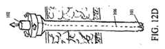
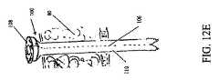
ステップ1:本明細書中で説明された特定の処置のために、臍周囲の腹腔鏡と二つの手術のためのトロカールが左右の下腹部の四半部に配置された後、一方のトロカールが取り除かれて、挿入シースアッセンブリを装備した専門トロカールと取り替えられる(図12A−12D参照)。 Step 1: For the specific procedure described herein, a peri-umbilical laparoscope and two surgical trocars are placed in the left and right lower abdominal quadrants, and then one trocar is removed. And replaced with a specialized trocar equipped with an insertion sheath assembly (see FIGS. 12A-12D).
ステップ2:専門トロカールのトロカールボタンが押されて、さぐり針が挿入シースの末端部を突き通し、トロカールが挿入シースから取り除かれる。そして、切除装置は、挿入シースの中に挿入される(図12G)。この実施形態の切除装置の顎部分が曲線で設計されているので、挿入シースの可撓性は、皮下にある予備腹膜あるいは腹直筋区分に迷わないで腹腔の中に切除装置の配置するのを許容する。肥満体の患者の腹壁は肥満体でない患者の腹壁よりも厚いかもしれないので、専門トロカール及び挿入シースは、肥満体の患者の使用に特に役立つ。ひとたび切除装置が腹腔に配置されると、挿入シースは切除装置から離れる方向に引っ張られて捨てられることができる(図13参照)。 Step 2: The trocar button of the specialized trocar is pushed, the search needle penetrates the distal end of the insertion sheath, and the trocar is removed from the insertion sheath. The ablation device is then inserted into the insertion sheath (FIG. 12G). Since the jaw portion of the ablation device of this embodiment is designed with a curve, the flexibility of the insertion sheath allows the ablation device to be placed in the abdominal cavity without obscuring the subcutaneous peritoneum or rectus abdominis muscle section. Is acceptable. Specialized trocars and insertion sheaths are particularly useful for use with obese patients, since the abdominal wall of an obese patient may be thicker than the abdominal wall of a non-obese patient. Once the ablation device is placed in the abdominal cavity, the insertion sheath can be pulled away from the ablation device and discarded (see FIG. 13).
ステップ3:切除装置の通常状態のように、顎部分は開くことができる(図15)。切除装置は、電気外科的処置される骨盤構造上に配置され、そして、電気外科的処置される骨盤構造が顎部分の組織接触領域と接触するように使用者は顎トリガーを絞る(図16及び図18)。切除装置が顎トリガーロックを装備している場合、そのロックは同時に係合されることができる。電極セレクターが顎部分の重金属接触に電気外科エネルギーを導くように、使用者は電極セレクターのボタンを付勢する顎部分を押す。フットペダルは、顎部分間で保持された組織を電気外科的処置するための電気外科エネルギーを起動させるために押し下げられる。 Step 3: The jaws can be opened as in the normal state of the ablation device (FIG. 15). The ablation device is positioned on the pelvic structure to be electrosurgically treated and the user squeezes the jaw trigger so that the pelvic structure to be electrosurgically contacted with the tissue contacting area of the jaw portion (FIGS. 16 and 16). FIG. 18). If the ablation device is equipped with a jaw trigger lock, the lock can be engaged simultaneously. The user depresses the jaw portion that energizes the button on the electrode selector so that the electrode selector directs electrosurgical energy to the heavy metal contact of the jaw portion. The foot pedal is depressed to activate electrosurgical energy for electrosurgical treatment of tissue held between the jaws.
ステップ4:使用者は、電極セレクターのブレード付勢ボタンボタンを押して、(地上接触として顎部分電極を利用する)二極式ブレードを選択する。ブレードは、フットスイッチを作動している間進められて、血管と組織を分けるように血管と組織を電気外科的に処置する。顎部分が骨盤構造の反対側の表面(図18)をたどり、ステップ1−4が反対側の組織に対して行われるように、切除装置のハンドルは180度回転する。子宮摘出術では、曲がった顎部分は、使用者が膀胱子宮窩ひだのレベルで子宮頸部接合に隣接して骨盤組織にすぐに容易にアクセスするのを許容する。 Step 4: The user selects the bipolar blade (using the jaw partial electrode as ground contact) by pressing the blade energizing button button on the electrode selector. The blade is advanced while actuating the foot switch to electrosurgically treat the blood vessel and tissue to separate the blood vessel and tissue. The excision device handle is rotated 180 degrees so that the jaw portion follows the opposite surface of the pelvic structure (FIG. 18) and steps 1-4 are performed on the opposite tissue. In hysterectomy, the bent jaw allows the user easy and immediate access to pelvic tissue adjacent to the cervical junction at the level of the bladder uterine fold.
ステップ5:前方の膀胱子宮窩ひだは、顎部分で根元が削り取られて締め付けられる(図19)。顎付勢ボタンが再び選択され、フットスイッチが作動されて、組織は電気外科的に処置される。この点で、顎付勢ボタンは、ブレードに送られる電気外科エネルギーブレードを利用するのに選択されることができる。膀胱子宮窩ひだの組織は、使用者がブレードを作動させることによって分けられて、顎部分間に保持された組織を分ける。顎部分は、下の子宮部分から膀胱を遠慮なしに切断するのに使用されることができる。 Step 5: The anterior bladder hyoid fold is tightened with the roots scraped off at the jaw (FIG. 19). The jaw bias button is again selected, the footswitch is activated, and the tissue is electrosurgically treated. In this regard, the jaw bias button can be selected to utilize an electrosurgical energy blade that is delivered to the blade. The tissue of the bladder uterine fold is divided by the user operating the blade to separate the tissue held between the jaw parts. The chin portion can be used to casually cut the bladder from the lower uterine portion.
ステップ6:電気モーターがワイヤーループを展開する方向にワイヤースプールを回転させるように、ワイヤーループスイッチが配置される。ワイヤーループは、子宮の上部に配置され、そして、子宮頸部接合部近傍の子宮頸に隣接して配置される(図20)。電極セレクターが電気外科エネルギー源からワイヤーループまでの回路を開くように、切除装置のワイヤーループ付勢ボタンは選択される。電気モーターがワイヤーループを収縮させる方向に回転させるように、ワイヤーループスイッチが配置されている。ワイヤーが子宮顎に対してきついとき、フットスイッチは作動され、電気外科エネルギーをワイヤーループに与える。ワイヤーループと、切除装置の末端部上の接触プレートは、ループワイヤーに
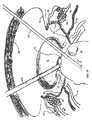
ワイヤーループと接触した子宮頸部接合部で組織を電気外科的に処理させる回路を完成する。この点で、ワイヤーループは、ワイヤーループと接触した組織をさらに分けるように収縮させることができる(図21)。Step 6: The wire loop switch is arranged so that the electric motor rotates the wire spool in the direction to deploy the wire loop. The wire loop is placed at the top of the uterus and adjacent to the cervix near the cervical junction (FIG. 20). The ablation device wire loop activation button is selected so that the electrode selector opens the circuit from the electrosurgical energy source to the wire loop. A wire loop switch is arranged so that the electric motor rotates in a direction that causes the wire loop to contract. When the wire is tight against the uterine jaw, the footswitch is actuated, providing electrosurgical energy to the wire loop. The wire loop and contact plate on the distal end of the ablation device complete the circuit that causes the loop wire to electrosurgically treat tissue at the cervical junction in contact with the wire loop. In this regard, the wire loop can be contracted to further divide the tissue in contact with the wire loop (FIG. 21).
ステップ7:切除された骨盤構造は、分割器を使って取り除かれる。腹部は空気を抜かれ、器具は取り除かれ、切開は閉じられ、そして、傷包帯が配置される。 Step 7: The excised pelvic structure is removed using a divider. The abdomen is deflated, the instrument is removed, the incision is closed, and a wound dressing is placed.
2.装置の特徴
従来の外科手術装置の各々(特に腹腔鏡または内視鏡処置に使用される外科手術装置)の弱点を分析後、劇的に外科的な手術時間を減少させ、安全性と安定性を改善し、利便性を増すこの切除装置のいくつかの主な特徴がある。2. Device Features After analyzing the weaknesses of each of the conventional surgical devices (especially surgical devices used for laparoscopic or endoscopic procedures), it dramatically reduces the surgical operation time, safety and stability There are several main features of this ablation device that improve and increase convenience.
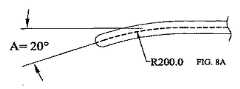
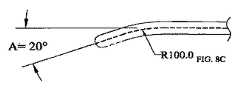
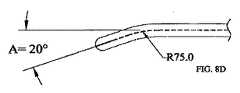
一実施態様では、顎アプリケーションサイトは、実行される手順に従って特定の骨盤血管組織に適応させるために曲がっている(図8A−D)。特に、顎部分は、人間の子宮の外湾曲を倣うために曲げることができる。片持ち顎部分構造は、より多くの組織が顎部分の末端部での垂直クリアランスの増加を必要としないで顎部分間で保持されるのを許容する(すなわち、切り取る効果が無い)。 In one embodiment, the jaw application site is bent to adapt to specific pelvic vascular tissue according to the procedure performed (FIGS. 8A-D). In particular, the jaw part can be bent to follow the external curvature of the human uterus. The cantilever jaw structure allows more tissue to be retained between the jaws (ie, has no cutting effect) without requiring increased vertical clearance at the end of the jaw.
テフロン(商標名)でコーティングされた重金属接触部は、組織に電気外科エネルギーを送るための組織接触領域を形成するために、堅くて熱安定したポリマー体に融和することができる。これは、顎部分が熱変形に抵抗するのを許容し、使用者が電気外科組織治療の間圧力をかけるのを許容する。さらに、顎部分は、長さを最高16センチメートルにすることができ、従って、利用可能な最大の内視鏡の電気外科エネルギー送出面を提供する。これは、正確な解剖的な配置でとても速い切断速度を許容する(図16及び図18)。テフロン(商標名)コーティングは、電気外科的に治療した組織が顎部分の加圧に従う組織接触領域に引っかかるのを防止する。半導体チップが、第1顎部分及び第2顎部分の組織接触領域間の電気外科エネルギーを交替させるのに使用することができ、それは、組織の冷却を容易にし、外側の熱ダメージを制限し、電気外科治療を良くする。
使用者によって選ばれた電極以外のあらゆる電極に電気外科エネルギーが流れるのを防止する独特な電極セレクターは、使用者によって望まれた電極以外の電極からの不注意なエネルギーの放出を避けることによって安全性を加える。図16及び18に示されるように、子宮の一方側全体は、殆どの場合すぐに治療される。
一実施態様では、絶縁されたロッドは、独特なブレードアッセンブリにはんだ付けされる(本明細書で示された実施態様ではブレードアッセンブリは使用されない)。電線管は、ハンドルの範囲内でブレード及び/叉はブレードアッセンブリに付属し、電気外科エネルギー用管を提供する。ブレードはブレードトラックに沿って前方に移動するので、両極性の電気外科エネルギーがブレードと接触して組織を治療するように電極セレクターを配置することができる。A heavy metal contact coated with Teflon can be blended into a rigid, heat stable polymer body to form a tissue contact area for delivering electrosurgical energy to the tissue. This allows the jaw portion to resist thermal deformation and allows the user to apply pressure during electrosurgical tissue treatment. Further, the jaw portion can be up to 16 centimeters long, thus providing the largest endoscopic electrosurgical energy delivery surface available. This allows very fast cutting speeds with accurate anatomical placement (FIGS. 16 and 18). The Teflon ™ coating prevents electrosurgically treated tissue from getting caught in the tissue contact area following the pressurization of the jaw. A semiconductor chip can be used to alternate the electrosurgical energy between the tissue contact areas of the first jaw portion and the second jaw portion, which facilitates tissue cooling, limits external thermal damage, Improve electrosurgical treatment.
A unique electrode selector that prevents electrosurgical energy from flowing to any electrode other than the electrode chosen by the user is safe by avoiding inadvertent release of energy from electrodes other than those desired by the user Add sex. As shown in FIGS. 16 and 18, the entire side of the uterus is most often treated immediately.
In one embodiment, the insulated rod is soldered to a unique blade assembly (the blade assembly is not used in the embodiment shown herein). The conduit is attached to the blade and / or blade assembly within the handle to provide a tube for electrosurgical energy. As the blade moves forward along the blade track, the electrode selector can be positioned so that bipolar electrosurgical energy contacts the blade and treats the tissue.
切除装置の両手のきくハンドルは、骨盤構造の両側を効果的に治療するため、及びワイヤーロープの展開を容易にするために180度回転させることができる。独特なワイヤーロープ(特定の実施態様に対して存在する場合)は、ワイヤーループスイッチを適当な位置へ動かすことによって展開されることができる。電動化スプールは、ワイヤーループを解き、それは、ワイヤーループが子宮の上で展開されるかもしれないので子宮摘出処置にとって特に便利である。ひとたび、ループが子宮の上を置かれると、使用者は、電気モーターを逆転させるためにワイヤーループスイッチを適当な位置へ動かすことができ、それによって、ワイヤースプールを逆巻きにし、ワイヤーループを子宮顎に対してしっかりと収縮する(図21)。電極セレクターは、電気外科エネルギーをワイヤーループに通過するのを許容するために配置され、それは、ワイヤーループと接触した組織を電気外科的に治療する。 The hand handle of the resection device can be rotated 180 degrees to effectively treat both sides of the pelvic structure and to facilitate the deployment of the wire rope. A unique wire rope (if present for a particular embodiment) can be deployed by moving the wire loop switch to the appropriate position. The motorized spool unwinds the wire loop, which is particularly convenient for hysterectomy procedures because the wire loop may be deployed over the uterus. Once the loop is placed over the uterus, the user can move the wire loop switch to the proper position to reverse the electric motor, thereby reversing the wire spool and moving the wire loop to the uterine jaw. It shrinks tightly against (Fig. 21). The electrode selector is positioned to allow electrosurgical energy to pass through the wire loop, which electrosurgically treats tissue in contact with the wire loop.
ワイヤーループに同時にエネルギーを付与している間のワイヤーループの収縮は、2,3秒で子宮頸を止血的に切断するのに使用されることができる。それから、子宮は完全に切断され、内視鏡分割器(Gynecare Morcellator参照)を使用する内視鏡除去のために準備される。代替的な実施態様では、ワイヤースプールは、ワイヤースプールハンドルを含み、使用者は、ワイヤーループを手動的に収縮及び展開をすることができる。 The contraction of the wire loop while simultaneously energizing the wire loop can be used to hemostatically cut the cervix in a few seconds. The uterus is then completely cut and prepared for endoscopic removal using an endoscopic divider (see Gynecare Morcellator). In an alternative embodiment, the wire spool includes a wire spool handle that allows the user to manually retract and deploy the wire loop.
無線周波数(Rf)エネルギーは、組織に送られた熱エネルギーを下げ、過剰な外側の熱ダメージを減少する。通常の電気外科装置は、数百度(最高800℃)の温度を達成し、最高800ボルトで150乃至300ワットの範囲で作動する。本切除装置は、80ボルトで10乃至15ワットの無線周波数出力で作動し、過剰な外側の熱の組織ダメージを最小にする。 Radio frequency (Rf) energy lowers the thermal energy delivered to the tissue and reduces excessive outside thermal damage. Typical electrosurgical devices achieve temperatures of several hundred degrees (up to 800 ° C.) and operate in the range of 150 to 300 watts at up to 800 volts. The ablation device operates at 80 volts and a radio frequency output of 10-15 watts to minimize excessive outside thermal tissue damage.
3.代表的な実施態様の全般的な説明 3. General description of representative embodiments

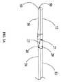
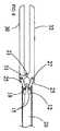
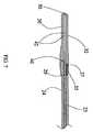
図を参照すると、多極電気外科切除装置10が示されている。卵管卵巣切除を有する叉は有さない、腹腔鏡子宮膣上部切断、腹腔鏡子宮全切断、腹腔鏡補助下膣式子宮全摘出、腹式子宮全摘出、及び/叉は腹式子宮膣上部全摘出のために設計された本明細書中に示された特定の実施態様を有する、切除装置10は、外科処置の使用のために設計されている。しかしながら、切除装置10は、特に、腎臓切除、脾臓切除など、切開手術や他のタイプの内視鏡手術叉は腹腔鏡手術に使用することもできる。図1に示された実施形態では、切除装置10は、顎トリガー70を有するハンドル22に取り付けられたシャフト20で構成される。顎トリガー70は、図2及び2Aに図示されたスプリング機構60に関連して作動し、第1顎部分30に対する第2顎部分32の位置を操作する。協働して、顎部分30,32は、組織を把持するのに使用することができる。切除装置10は、顎トリガー70の位置をロックするためのスプリングが装填された顎トリガーロック(図示せず)と適合されることができ、それによって、顎部分30、32の位置をお互いにロックする。また、この実施態様では、マルチポジション電極セレクター62がハンドル22に取り付けられている。ハンドル22は、特定の適用のために適当な材質で構成されることができ、その材質は、高密度ポリエチレン、アルミニウム、ポリエステル、あるいは他の適当な材質などの当業者に周知なものである。本明細書中に示されていない実施態様では、ハンドル22は、透明叉は半透明な材質で構成されており、照明源がハンドル22内に配置され、使用の容易のためにハンドル22を照明する。代替的に、ハンドル22は、露光後に輝く、従来技術ですでに開示した材質でつくることができる。ハンドル22の構成は、特許請求の範囲に記載されたようなハンドル手段の一つのタイプから成る。 Referring to the figure, a multipolar
代表的な実施態様では、ハンドル22は、幅がほぼ等しい二つの部分で合わせられている。ハンドル22内の種々の構成要素が、特定の実施態様において密閉されることができる。例えば、切除装置10が自動ワイヤースプール53、電極セレクター62及び関連ボタン、及び/叉はハンドル22を照明するための内光(図示せず)、及び/叉はボタン66、67、68を備えている場合、各構成要素が他の構成要素及びハンドル22の外部の環境から密閉的及び電子的に保護されるように、ハンドル22は適合されることができる。すなわち、電気モーター51を収容するハンドル22の部分は、電気モーター51が空気、水、及び/叉は切除装置10の他の部分からの電子干渉、及び/叉は切除装置10の他の外部要素から密閉されるように適合されることができる。ハンドル22の部分は、ハンドル22のその部分内に配置された一つまたは複数の構成要素のための同様なシールを提供するように適合されることができ、ハンドル22の密閉部分内に配置された切除装置10の構成要素は、特定の実施態様に依存して変更する。 In the exemplary embodiment, handle 22 is mated in two portions that are approximately equal in width. Various components within the
図1、1A、2、2A、7、7A、9、10、10A及び10Bに示された代表的な実施態様のシャフト20及びハンドル22の一部分は、両極切断ブレード40及び両極ワイヤーループ50が収縮位置にあるときに両極切断ブレード40及び両極ワイヤーループ50を収容する。切除装置10のシャフト20は、耐熱性ポリマー叉はアルミニウム、金属またはそれらの合金などの当業者に周知な他の適当な材質で構成されることができる。代替的に、シャフト20は、複数の材質で形成されることができる。また、一つの単一部分としてよりもしろ異なる構成で形成されることができる。例えば、シャフト20は、異なる材質で作られたシェル内に配置された断熱及び絶縁体を提供する内部材質で形成されることができる。代表的な実施態様では、シャフト20は、摺動シャフト部分23及び固定シャフト部分24の二つの部分で形成される。摺動シャフト部分23は、固定シャフト部分24に対して軸方向に摺動する。第2顎部分32は、この実施態様において第2顎部分32の作動を容易にする摺動シャフト部分23に取り付けられている。図1、1A、2、2A及び10に示された実施態様では、シャフト20の軸部分は、シャフトシース11の中に収容される。シャフトシース11は、摺動シャフト部分23と固定シャフト部分24の双方の一部分を放射状に取り囲み、顎トリガー70が作動されたときに摺動シャフト部分23叉は固定シャフト部分24が曲がるのを防止する。顎部分30、32は、特許請求の範囲に記載されたような把持手段の一つのタイプである。 A portion of the
顎部分70及びスプリング機構60を示す、ハンドル22の内部構成要素の一実施態様の詳細な図が図2に示されている。ハンドル22の同じ実施態様の断面図が図2Aに示されている。代表的な実施態様のハンドル22は、切除装置10を調整する必要なしに使用者の右手または左手のどちらか一方で切除装置10を使用することができるように設計されている。ハンドル22の他の形状及び実施態様が当業者に明白であり、本明細書中に記載され開示された実施態様の変形が、本発明の精神及び範囲から逸脱しないで生じるであろう。ハンドル22がきつく握られると、顎トリガー70がシャフト20に関する軸方向にシャフト20から離れて動き、そして、ビーム76と連通する顎トリガービーム係合部74が、顎トリガー70に与えられた機械的な力によって同じ方向に動く。これは、互いに枢動的に係合されたビーム76がトランスレーター78に力を与えさせる。トランスレーター78は、トランスレーターコネクター13を通じて摺動シャフト部分23と機械的に係合される。この実施態様では、トランスレーター78は、シャフト20とディスクが共通の軸線を共有するように配置されたディスクとして適合されている。トランスレーター78は、トランスレーターコネクター13を通じて摺動シャフト部分23に連結され、摺動シャフト部分23、トランスレーター78及びトランスレーターコネクター13は、一部品として形成されることができる。スプリング機構60は、トランスレーター78を軸方向でシャフト20から離れる方向に付勢し、そして、摺動シャフト部分23を同じ方向に付勢し、それによって、外力が顎トリガー70にかかる場合を除いて顎部分30、32を隔離する。ハンドル22が使用者によってしっかりと把持され、顎トリガー70が押されると、ビーム76は、トランスレーター78をスプリング機構60の力に抗して動かし、そして、ビーム76からトランスレーター78に与えられた力がスプリング機構60のスプリング力を打ち負かすと、トランスレーター78は、摺動シャフト部分23を固定シャフト部分24に対して軸方向でハンドルから離れる方向に摺動させ、続いて、第2顎部分32を第1顎部分30の方へ動かす。 A detailed view of one embodiment of the internal components of
図1−2Aに示された実施態様のビーム76、顎トリガービーム係合部74、顎トリガー70、トランスレーターコネクター13、トランスレーター78、顎部分30、32の構成は、第2顎部分32の小さな移動量が顎トリガー70の大きな移動量に対応するのを許容する。すなわち、ビーム76の長さ及び配置と、ビーム76がトランスレーター78と係合する仕方は、顎部分の特定の移動量(例えば2ミリメートル)に、第2顎部分32の対応するが等しくない小さな移動量(例えば0.2ミリメートル)をもたらさせる。また、顎トリガー70の移動量から第2顎部分32の移動量への移行は、当業者に周知であるように、使用者が、顎トリガー70にかけられた付与力で第2顎部分32により大きな力を伝達するのを許容する。顎トリガー70の移動と、対応する第2顎部分32の移動との間の特定の比率は、切除装置10の特定の応用に対して調整されることができ、従って、それによって達成される特定の実施態様あるいは比率は本発明の範囲を制限しない。顎トリガー70、ビーム76、顎トリガービーム係合部74、トランスレーターコネクター13及びトランスレーター78は、特許請求の範囲に記載されたような一つの作動手段である。 The configuration of the
第1顎部分30及び第2顎部分32の一実施態様の詳細図が図3−3Bに示されている。図3に示されるように、リンク25は、逆に摺動シャフト部分23から第2顎部分32への力を連通するのに役に立つ。上述したように、スプリング機構60は、使用者が顎トリガー70を作動しない限り第1顎部分30を第2顎部分32から隔離させる(すなわち、図3に示された位置)力をかける。(関連したリンクで)第2顎部分32は、第1顎部分30と協働し、一組のカンチレバー顎部を形成する。顎トリガー70が作動されると、
摺動シャフト部分23をシャフト20の軸線に沿ってハンドル22から離れる方向に移動し、リンク25が、図3に示された位置から図3Aに示された位置に移動する。この移動中、リンク25は、第2顎部分/リンクコネクター27、摺動シャフト部分/リンクコネクター29及び固定シャフト部分/リンクコネクター28を中心にして枢動する。リンク25の中のピン26、(ピン開口36内にピン26を固定するのに機能する)ピンキャップ38及び関連したピン開口36及び第2顎部分32(それらの全てが図10Bに最もよく示されている)は、第2顎部分32をリンク25に機構的に連結する第2顎部分/リンクコネクター27を構成する。リンク25の中のピン26、ピンキャップ38及び関連したピン開口36及び摺動シャフト部分23は、摺動シャフト部分23をリンク25に機構的に連結する摺動シャフト部分/リンクコネクター29を構成する。リンク25の中のピン26、ピンキャップ38及び関連したピン開口36及び固定シャフト部分24は、固定シャフト部分24をリンク25に機構的に連結する固定シャフト部分/リンクコネクター28を構成する。本発明の範囲から逸脱しないでピン26、ピンキャップ38及びピン開口36以外の構造が、切除装置10の種々の移動要素を機構的に連結するのに使用することができる代替的な実施態様が存在する。図10Bが、上述の各構成要素のピン26、ピンキャップ38及びピン開口36及びこれらの互いの関係を最もよく示す。第2顎部分32が第1顎部分30に関して整合しなくなるのを防止するため、スロット31が第1顎部分30の両面に適合され、第2顎部分の両面に形成された二つのノブ21がスロット31と摺動的に係合されている(図10Bに最もよく示す)。図3Bは、リンク25のシャフト20の軸線に対して垂直な断面図を提供し、ノブ21が配置されるリンク25の部分を示す。A detailed view of one embodiment of the
The sliding
第1顎部分30及び第2顎部分32の代替的な実施態様の詳細な図が図4及び図4Aに示されている。この実施態様では、摺動スリーブ12は、シャフト20に関して軸方向にシャフト20と摺動的に係合されている。この実施態様では、シャフト20は、(摺動シャフト部分23及び固定シャフト部分24を有する前に述べた実施態様の構造に対して記載されたような)二つの部分よりもむしろ一つの部分で構成される。第2顎部分/リンクコネクター27は、図3−3Bに示された実施態様の第2顎部分/リンクコネクター27と同じであるが、関連したピン26、ピンキャップ38及びピン開口36は、図4及び図4Aに示された実施態様では分離して示されていない。この実施態様では、リンク25の一部分は、シャフト20の内部の中にある。図4のダッシュ線内の領域は、シャフト20の内部部分を表す。顎トリガー70が押されると、摺動スリーブ12が顎部分32、33の方へ動き、そして、摺動スリーブ12の(ハンドル22に対する)末端部がリンク25上を動き、第2顎部分32を第1顎部分30の方へ押圧する。この動作中、リンク25は、シャフト/リンクコネクター14を中心にして枢動する。この実施態様の第1顎部分30の二つのスロット31に対応する第2顎部分32の二つのノブ21は、図3−3Bに示された実施態様のノブ21及びスロット31と同様である。ノブ21及びスロット31は、第2顎部分32が第1顎部分30と整合しない状態に保持する。第2顎部分32が図4に示された位置から図4Aに示された位置に作動されるとき、シャフト20に形成されたリンク溝15は、第2顎部分/リンクコネクター27の反対位置にあるリンク25の端部と摺動的に係合し、リンク25によって変位する軸の長さの違いの原因となる。 Detailed views of alternative embodiments of the
第1顎部分30及び第2顎部分32の代替的な実施態様の詳細な図が図5及び図5Aに示されている。この実施態様は、図3−3Bに示された実施態様と同様であり、シャフト20は、摺動シャフト部分23と固定シャフト部分24で形成されている。しかしながら、図5及び図5Aの実施態様は、ピン開口36と関連したピン26及びピンキャップ38の使用などの当業者に周知な便宜方法で第1顎部分30及び第2顎部分32の双方に連結された第2リンク16を使用する。第2リンク16は、第2顎部分32が第1顎部分30に対して整合するのを確実にする。従って、第1顎部分30に適合された二つのスロット31と、第2顎部分の両面に形成された二つの対応するノブ21は、この実施態様では必要としない。顎部分30、32の動作は、この実施態様では、図3−3Bに示された実施態様と実質的に同じである。しかしながら、図5及び図5Aで見られることができるように、顎部分30、32の使用できる部分は、第2リンク16の存在のせいでこの実施態様で減少される。 Detailed views of alternative embodiments of the
第1顎部分30及び第2顎部分32のさらに代替的な実施態様の詳細な図が図6及び図6Aに示されている。この実施態様では、第1顎部分30及び第2顎部分32の双方が、顎部分70の作動中動く。顎部分30、32の前に述べた全ての実施態様では、第2顎部分32だけが顎部分70の作動中動いた。図4及び図4Aに示された実施態様の場合のように、摺動スリーブ12はシャフト20に関して軸方向にシャフト20と摺動的に係合され、そして、シャフト20は二つの部分よりはむしろ一つの部分で構成される。この実施態様では、セパレーター18は、二つのリンク25の間に配置され、その一方が第1顎部分30とシャフト20に取り付けられ、その他方が第2顎部分32とシャフト20に取り付けられる。スプリング機構60は、セパレーター18をハンドル22の方へ軸方向に付勢し、そして、セパレーター18は、各々のリンク25上で動作して顎部分30、32を互いに離れる方向に付勢する。顎トリガー70が作動されたとき、摺動スリーブ12は、顎部分30、32の方へシャフト20に沿って動き、顎部分30、32が互いに付勢するようにそれぞれのリンク25上で動く。図4及び図4Aに示された実施態様と同じように、シャフト20に形成された一対のリンク溝15は、第2顎部分/リンクコネクター27及び第1顎部分30の対応するコネクターの反対位置にある各リンク25の端部と摺動的に係合する。顎部分30、32が図6に示された位置から図6Aに示された位置に作動されるとき、リンク溝15は、リンク25によって変位された軸の長さの違いの原因となる。第1顎部分30の二つのスロット31は、第2顎部分30に形成された二つのノブ21に対応し、図3−3Bに示された実施態様のスロット31及びノブ21に対して記載されたのと同じように、顎部分30、32の不整合を防止する。 A detailed view of a further alternative embodiment of the
本明細書中に示され記載された全ての実施態様において、顎部分30、32のデフォルト位置が図3、4、5及び6に示され、その位置では、顎部分30、32は分離されている。しかしながら、デフォルト位置が本明細書中に示されたデフォルト位置と異なる他の実施態様が存在する。図3−6Aに示された第1及び第2顎部分30、32の種々の実施態様は、使用者が、締めることができる従来の装置よりも、顎トリガー70の一つの動作で顎部分30、32の間でより多くの組織を締めるのを許容する。この利点は、顎部分30、32の間の間隔が顎部分30、32の長さに沿って一定なので理解される。(従来技術の装置にあるような)切り抜き動作がないので、本発明の顎部分30、32の最も末端部分は、顎部分30、32の最も基端部分と同じ間隔で隔てられている。これは、従来技術の装置と比較して顎部分30、32がより長くなるのを許容し、そのため、顎トリガー70の一つの動作で顎部分30、32によってより多くの組織を締め付けることができると共に電気外科的に治療されることができる。他の利点の間で、これは、より速い外科的処置を容易にし、電気外科的に処理される組織の正確さを増加し、より少ない失血に起因する。 In all of the embodiments shown and described herein, the default positions of the
第1顎部分30と第2顎部分32の双方は、テフロン(商標名)あるいは当業者に周知な他の材質など、焦げ付かない耐熱性のある金属で覆われた重金属接触(図示せず)で作られ、(図10−10Bに最もよく示された)各顎部分30、32に対して組織接触領域34を形成する。電気外科的エネルギー源は、電線管44を介して顎部分30、32の重金属接触に連結されることができる(以下の説明されるように、電極セレクター62を通じて電気外科的エネルギーは送られる)。電線管44は、特許請求の範囲に記載されたような、組織接触領域34を電気外科的エネルギー源に連結するための一つの手段である。組織接触領域34は、顎部分30、32の組織接触領域34と接触した組織に電気外科的エネルギーを導くための二重配列した電気外科エネルギー組織把持電極として使用される。すなわち、顎部分30、32の間の組織を通じて電気外科的エネルギーを導くために、第1顎部分30の組織接触領域34は、一つの電極として使用でき、第2顎部分32の組織接触領域34は、第2の電極として使用できる。組織接触領域34は、特定の実施態様に依存して、顎部分30、32の把持面全体またはその一部分に沿って伸びることができる。組織接触領域34上の引っかからないコーティングは、凝固した血あるいは電気外科的治療した組織が組織接触領域34に引っかかるのを防止する。粘着性のある組織凝固物は、顎部分30、32を電気外科的に治療した組織から引き抜く間にもろい電気外科的治療した組織を引き裂く場合があり、その結果、出血が生じる。一実施態様では、半導体チップ(図示せず)が、顎部分30、32の重金属接触間の(無線周波数(Rf)を含む、電気外科的エネルギー源が送ることができる周波数及び振幅である)電気外科的エネルギーを交替する。ハンドル22内または同じように便宜な位置に配置することができる半導体チップは、不規則に電気外科的エネルギーを交替して、最小の外部の熱拡散で最大の組織の電気外科的治療を許容し、それによって、組織接触領域34の外側の組織の最小量が電気外科エネルギーによってもたらされることを確実にする。組織抵抗フィードバックに基づいて、半導体チップは電流を交流する。より高いパワーセッティングは、低いパワーセッティングが引き起こすよりも、より速い電流振幅を引き起こす。この電気外科エネルギーの代替は、組織接触領域34をわたる熱エネルギーのより均一な堆積を生じる。組織接触領域34は、本発明の精神及び範囲から逸脱しないで他の形状及び配置をとることができ、半導体チップは、切除装置10の便利なあらゆる位置に配置することができ、あるいは特定の応用によって示されるように切除装置10の外部に配置することができる。 Both the
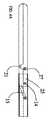
顎部分30、32の代表的な実施態様では、図8A−8Dに最もよく示されるように、顎部分30、32は、人間の子宮の外壁の湾曲に合うように曲げられているが、直線状の顎部分30、32を含む、顎部分30、32の他の湾曲が、本発明の範囲内に含まれる。本明細書中に示されていない代替的な実施態様では、子宮切除以外の特定の外科処置を容易にするために曲げられることができる。図8A−8Dにわたって、ダッシュ線は、シャフト20及び顎部分30、32を通過するブレードトラック42を示す。図8A−8Dに示されるように、顎部分30、32の湾曲は、特定の実施態様に依存する、異なる半径を有する円から導かれる。図示しないが、顎部分30、32は、ハンドル22に近い直線状シャフト20の部分と、シャフト20及び/叉は顎部分30、32の湾曲から離れた直線状の顎部分30、32の部分との間で異なる角度を有する。図8A−8Dに示される実施態様では、この角度(すなわち、顎部分30、32の湾曲から離れた直線状の顎部分30、32の部分と、ハンドル22に近い直線状シャフト20の部分との間の角度)は、“A”で示され、20度の値を有する。図8A−8Dに示されたいくつかの実施態様では、直線状のシャフト20部分と、顎部分30、32の先端部分との間の直線状の差異は、15ミリメートルである。すなわち、顎部分30、32の端部は、シャフト20の直線部分から15ミリメートルだけずれている。しかしながら、特定の実施態様あるいは切除装置10が配置される特定の使用に依存して、本発明の精神及び範囲から逸脱しないで必要なように調整されることができる。 In an exemplary embodiment of the
図8Aに示された実施態様は、200ミリメートルの半径を有する円に起因する湾曲を示す。図8Bに示された実施態様は、150ミリメートルの半径を有する円に起因する湾曲を示し、図8C及び図8Dの実施態様は、それぞれ100ミリメートル及び75ミリメートルの半径を有する円に起因する湾曲を示す。図8A−8Dから明白であるように、湾曲を作り出すのに使用される円の半径が小さくなればなるほど、湾曲はより鋭角でより急になるのがわかる。本明細書中に開示された実施態様の湾曲の変形及び代替及びそれぞれの長さは、本発明の範囲から逸脱しないで当業者に生じるであろう。 The embodiment shown in FIG. 8A shows curvature due to a circle having a radius of 200 millimeters. The embodiment shown in FIG. 8B shows curvature due to a circle with a radius of 150 millimeters, and the embodiments of FIGS. 8C and 8D show curvature due to a circle with radii of 100 millimeters and 75 millimeters, respectively. Show. As is apparent from FIGS. 8A-8D, it can be seen that the smaller the radius of the circle used to create the curvature, the sharper and steeper the curvature. Variations and alternatives to the curvature and alternative lengths of the embodiments disclosed herein will occur to those skilled in the art without departing from the scope of the invention.
ブレード40は、ブレードトラック42に沿って作動し、ブレードトラック42は、シャフト20の摺動シャフト部分23と固定シャフト部分24の双方、(特定の実施形態に依存する)リンク25、及び顎部分30、32を通じて伸びる。代表的な実施態様に対するブレードトラック42の配向は、図3B、7A、7B、9及び10Bに最もよく示される。ブレード40は、顎部分30、32の間で保持された組織を分けるのに使用される。本明細書中に示された実施態様では、(図3A、4A、5A及び6Aに示されるように)顎部分30、32が互いに接したときに、ブレード40が顎部分30、32を通じて伸びるブレードトラック42の部分を通過することができる十分なクリアランスのままであるような寸法に、ブレード40及びブレードトラック42は適合されている。本明細書中に示された実施態様では、ブレード40は、シャフト20の長さ全体に伸び、ブレードアクチュエーター46に直接的に連結されている。代替的な実施態様では、ブレード40は、連続的にブレードアクチュエーター46に連結される絶縁ブレードアッセンブリ(図示せず)と機械的に係合されることができる。また、ブレード40(あるいは特定の実施態様に依存するブレードアッセンブリに依存するブレードアッセンブリ)は、ワイヤー叉は伝導性ハブなどの電線管によって直接連結されるか、(以下に説明されるように直接的に、あるいは電極セレクター62を通じて)一連の単極伝導性要素によって、電気外科的エネルギー源に連結されることができる。ブレード40、ブレードトラック42、ブレードアクチュエーター46及び(もし有していれば)ブレードアッセンブリの構成は、特許請求の範囲に記載されたような機械的切除手段の一つのタイプを構成する。 The
ブレードアッセンブリを含む特定の実施態様では、ブレード40が電圧を加えられたときに、電気外科的エネルギーがブレード40からブレードアッセンブリに流れないように、叉はブレードアッセンブリから切除装置10の他の伝導性構成要素に流れないように、ブレードアッセンブリは、電気的に絶縁されなければならない。ブレードアッセンブリが使用されない場合(すなわち、ブレード40がブレードアクチュエーター46に直接的に連結されている場合)、ブレード40の外面に絶縁材料をつけることによって、あるいはブレード40と接触する切除装置10の全ての部分が電気的に絶縁されるのを確実にすることによって、シャフト20に収容されるブレード40の部分は、電気的に絶縁されなければならない。電圧を加えられたときに、ブレード40は、一方の電極として供され、そして、第1顎部分30の組織接触領域34、第2顎部分32、叉はその両方が対応する電極として供され、ブレード40と接触した組織に電気外科的エネルギーを送る両極式手段を作る。ブレードトラック42に沿ったブレード40の位置は、ハンドル22と摺動的に係合されるブレードアクチュエーター46の位置によって決定される。すなわち、ブレードアクチュエーター46は、ハンドル22に対して動き、そして、ブレード40(及び実施態様に依存するブレードアッセンブリ)は、同じ量で同じ方向に動く。トラック42に沿ったブレード40の移動制限は、特定の実施態様に依存して変更されるが、典型的に、ブレードは、少なくとも組織接触領域34の軸方向の長さを移動する。本明細書中に示されていない他の実施態様では、ブレードトラック42は、顎部分30、32の最も先端部分に伸び、ブレードアクチュエーター46とハンドル22は、ブレード40がブレードトラック42の先端部を超えた小さい間隔で伸びて顎部分30、32の間の組織がブレード40のいっぱいの作動に基づいて分けられるのを確実にするように、形状付けられる。 In certain embodiments including a blade assembly, electrosurgical energy does not flow from the
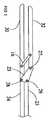
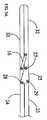
ワイヤーループ50は、シャフト20の(ハンドル2に対して)先端部に位置しており、そして代表的な実施態様では、図10及び10Aに最もよく示されている二つのワイヤー開口56を通って第1顎部分30から突き出る。ワイヤーループ50は、その一部分が代表的な実施態様ではハンドル22の内部に配置されているが代替的な実施態様では他の場所に配置されることができ、(シャフト20とハンドルの関連部分内に配置されている)電気的に絶縁された管59を通じてワイヤースプール53に伸びる。ワイヤーループ50は、
ポリマーコートされた金属、叉は切除装置10が使用される状態に適当な当業者に周知な他の適当な材質など、電気外科的エネルギーを伝えることができ十分な可撓性を提供する適当な材質で作られることができる。また、ワイヤーループ53は、代表的な実施態様でハンドル22の内部に配置される。ワイヤースプール53は、ワイヤースプール53をワイヤーループスイッチ54の位置に依存する二つの方向に回転させる電気モーター51と機械的に係合される。図1及び図2に示された実施態様では、ワイヤーループスイッチ54は、ハンドル22の外部に配置され、使用者の親指で容易に使用できる。ワイヤーループスイッチ54は、電気モーター51と電気的に連通し、ワイヤーループスイッチ54の位置は、電気モーター51の作動を制御する。ワイヤーループスイッチ54の第1の位置では、図10Aに示されるように、ワイヤーループ50をシャフト20から離れて展開する方向に電気モーター51はワイヤースプール53を回転する。ワイヤーループスイッチ54の第2の位置では、電気モーター51は、ワイヤーループスイッチ54が第1の位置にあるときにワイヤースプール53が回転する方向とは反対の方向にワイヤースプール53を回転させ、ワイヤーループ50は図10に示されるようにシャフト20の先端部の方へ収縮する。ワイヤーループスイッチ54は、電気モーター51が作動されず、従って、どちらの方向にも回転させない第3の位置を含む。また、ワイヤーループハンドル58は、ワイヤースプール53と機械的に係合されて、ワイヤーループ50を手動的に収縮及び展開する。電気モーター51は、バッテリー(図示せず)によって作動されることができ、または、(図11に示されるように)当業者に周知であるような適当な電気回路の使用を通じて典型的な壁のアウトレットから電力を供給されることができる。The
Any suitable polymer coated metal or other suitable material known to those skilled in the art suitable for the condition in which the
完全に収縮されると、ワイヤーループ50は、代表的な実施態様で第1顎部分30の先端部に取り付けれ、図10及び10Aに最もよく示されるコンタクトプレート52に接する。上述したように、ワイヤーループ50は、ワイヤー開口56を通じて第1顎部分30から突き出る。当業者に周知なように、コンタクトプレート52は、本発明の精神及び範囲から逸脱しないでシャフト20に沿った他の遠位の位置に配置することができる。完全に展開されると、ワイヤースプール53は、全てのワイヤーを本質的に出し、ワイヤーループ50は、特定の実施態様に依存して変更できる最も大きな円周を有し、完全に収縮されると、ワイヤーの大部分はワイヤースプール53と係合し、ワイヤーループ50は、最も小さな円周を有する。また、ワイヤーループ50は、ワイヤー叉は伝導性ハブなどの電線管44によって直接連結されるか、(以下に説明されるように直接的に、あるいは電極セレクター62を通じて)一連の単極伝導性要素によって、電気外科的エネルギー源に連結されることができる。ワイヤーループ50に電圧が加えられると、コンタクトプレート52は、ワイヤーループ50のアースの役割をし、二極式電気外科電気回路を形成する。ワイヤーループ50とワイヤースプール53の構成は、特許請求の範囲に記載されたような一つのループ手段を構成する。 When fully contracted, the
一つ以上の構成要素が電気外科的エネルギーで電圧が加えられる切除装置10の実施態様では、電極セレクター62が電圧が加えられる構成要素を選択するのに使用される。図11は、切除装置10の一実施態様の電気回路の簡略図を提供する。代表的な実施態様では、電極セレクター62の位置が使用者に容易に利用されやすい位置でハンドル22の外部にあるように、電極セレクター62が配置される。この電極セレクターの部分は、顎ボタン66、ブレードボタン67及びループボタン68から成る。上述のように、図11は、いくつかの電極(組織接触領域34、ブレード40、ワイヤーループ50)が電極セレクター62を通じて電気外科的エネルギー源とどのように連通できるかの簡略図を提供する。一実施態様では、電気外科的エネルギー源は、電気外科的エネルギーが電気外科的エネルギー源から電極セレクター62まで伝わるのを許容するために押される必要があるフットペダル64と直接連通する。フットペダル64を押して、電極セレクター62の特定の位置は、その位置に対応する電極を電気外科エネルギーで電圧を印加させる。顎ボタン66が押される場合、電極セレクター62は、顎部分30、32の組織接触領域34が電気外科エネルギーで電圧が印加されるのを許容し、ブレードボタン67が押される場合、電極セレクターは、ブレード40が電気外科エネルギーで電圧が印加されるのを許容し、そして、ループボタン68が押される場合、電極セレクター62は、ワイヤーループ50電気外科エネルギーで電圧が印加されるのを許容する。好ましくは、電極セレクター62は、あらゆる時に一つの構成要素だけが電圧が加えられるのを許容するロックアウト式スイッチである。すなわち、顎ボタンが押される場合、電極セレクターは、電気外科エネルギーがブレード40あるいはワイヤーループ50に通るのを許容しない。電極セレクター62のユーザーインターフェース(それぞれのボタン66、67及び68)は、暗い環境で適当な電極の選択を用にするように照明されることができる。ボタン66、67、68の照明は、露光後に輝く材質でボタン66、67、68を作ることによって、あるいは、周知な他の手段によって、ハンドル22の内部に照明球(図示せず)を配置することによって達成されることができる。また、周知なように、ボタン66、67、68は、ボタン66、67、68と電極セレクター62との間の境界面を密閉することにより水に抵抗するように形成されている。この密閉は、適当な接着剤、樹脂の熱形成、あるいは当業者に知られた他の適当な手段によって達成されることができる。代表的な実施態様では、ボタン66、67、68は、シリコン、ポリエチレン、ポリプロピレンまたは他の適当な材質などの半透明な可撓性材質で形成されている。代表的な実施態様では、顎ボタン66は緑、ブレードボタン67は黄色、ループボタン68は赤色であり、使用者は、ボタン66、67、68を容易に区別することができる。 In the embodiment of the
二つの構成要素だけが電気外科的エネルギー源に連結される切除装置10の実施態様では、電極セレクター62は、適当に作動する二つの位置を必要とするだけである。本明細書中に示されていない他の実施態様では、電極セレクター62は、ブレード40を印加する第1位置、第1顎部分30を印加する第2位置、第2顎部分32を印加する第3位置、ワイヤーループ50を印加する第4位置を含む多数の位置を有することができる。電極セレクター62は、ブレード40が電圧が印加されたときにどの顎部分30、32がアース電極として供するかを特定するさまざまな位置など、さらに他の位置を有することができる。従って、電極セレクター62のあらゆる実施態様において、特定の位置、位置が構成される仕方、それらの位置と構成の組み合わせは、本発明の精神及び範囲を限定しない。電線管44、ワイヤーループ50、コンタクトプレート52、ワイヤースプール53、ワイヤーループスイッチ54、絶縁管59、電極セレクター62、フットペダル64、顎ボタン66、ブレードボタン67及びループボタン68の構成は、特許請求の範囲に記載されたような把持手段及び/叉はループ手段で電気外科エネルギー源を連結及び/叉は作動する一つの手段を構成する。従って、電極セレクター62、フットペダル64、顎ボタン66、ブレードボタン67及びループボタン68の構成は、特許請求の範囲に記載されたようなエネルギーセレクター手段を構成する。 In the embodiment of the
以下に、腹腔鏡あるいは内視鏡手術で切除装置10の一実施態様を使用する手順を説明する。前述のように、切除装置10は、使用者が切除装置10が便利であるとわかるあらゆるタイプの外科処置で使用されることができ、そして、本明細書中に記載された特定の使用方法叉は外科処置は、本発明の範囲を限定しない。 The procedure for using one embodiment of the
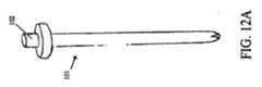
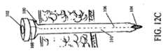
手術の対象の内部に腹壁80を通じた通路を提供するために鋭いトロカール(図示せず)が使用された後、(金属、ポリマー、複合物などの)特定の応用に適当な当業者に知られた材質で構成された、図12Aに示された特別なトロカール101は、トロカール101の外面の周囲に(図12B−図13に示された)ミシン目のついた可撓性挿入シース100を具備する。挿入シース100は、特定の外科処置に適当な可撓性材質で構成されることができる。一実施態様では、挿入シース100は、0.001ミリメートルから1ミリメートルまでの厚さをもつラテックスゴムで構成される。挿入シース100は、挿入シース体110の長さに沿ったミシン目106で形成されており、処理中のあらゆるときに外科用器具から分割され取り除かれることができる。ミシン目106は、挿入シース100の長さに対する一つ以上の軸方向の面に沿って伸びる。また、挿入シース100は、患者の外部にある挿入シース100の部分に挿入シースリング108で形状付けられている。挿入シースリング108は、外科用器具を挿入シース100の中へ入れる場所を提供し、挿入シース100が切開の中に落ちないのを確実にする。また、使用者が挿入シース100を取り除くのを望む場合に、挿入シースリング108は、挿入シース100の一部分が利用可能で可視できるままの状態にするのを確実にする。挿入シースリング108は、挿入シース体110と同じ材質または特定の利用に適当な他の材質で作られ、それは、材質が挿入シースリングに対して十分な剛性を与え、使用者が挿入シース100を容易に把持して取り除くのを許容する。 After a sharp trocar (not shown) is used to provide a passage through the
挿入シースリング108と反対側にある挿入シース100の端部は、(図12Bに示されるように)閉じられているが、以下に詳細に述べられるように、適当なツールで容易に穴をあけることができる。挿入シース100を取り除くために、使用者は、ミシン目106の両側にある単に挿入シースリング108を把持し、それぞれの部分を切開部から離れる方向に引き上げ、挿入シース体110及び挿入シースリング108を含む挿入シース100を図13に示すようにミシン目106に沿って分割する。本明細書中に示されていない他の代替的な実施態様では、ミシン目106は、挿入シース100の長さ全体に沿って伸びていない。 The end of the
挿入シース100を配置するために、トロカール101及び挿入シース100は、切開部を通じて腹腔、及び鋭いトロカールによって作られた腹壁80を通る通路の中に挿入される。トロカール101の挿入端部が腹壁80を通過すると、使用者は、トロカールボタン102を押し、それは、図12Cに示されるように、トロカール101内の茎状突起104をトロカール101の挿入端部を通じて突出させて挿入シース100の対応する端部を突き刺させる。それから、トロカール101は、挿入シース100から取り除かれ、切除装置10は、挿入シース100を通じて同じ切開部及び(図12Gに示された)腹壁80の通路の中に挿入される。次に、図14及び図15に示されるように、外科的用具は、子宮摘出を必要としている処置に対応する、行われる外科的処置に従って配置される。挿入シース100の可撓性設計は、切除装置10の曲がった顎実施態様を収容する。切開部の挿入シース100の存在は、切除装置10を不適切な位置に配置する(すなわち、皮下にある予備腹膜あるいは腹直筋区分に迷う)使用者の可能性を軽減する。また、挿入シース100は、手術が行われる患者の領域の中への切除装置10の適時の配置を容易にする。切除装置10のシャフト20が患者の方へ滑り落ちた場合に使用者が顎部分30、32の作動に関する妨害の前に挿入シース100を取り除くことができるように、挿入シース100は取り除き可能に設計されている。 To place the
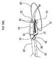
外科的処置が、LAVHまたは(卵管卵巣摘除を有する叉は有さない)腹腔鏡上子宮頸部の子宮摘出である場合、切除装置10は、図14及び図15に示されるように、子宮81に隣接して配置され、また把持鉗子112が使用される。このような配置は、すぐに(図18−21に示される)卵巣提索82、固有卵巣索83、子宮円索84、卵管85、広間膜86及び外側子宮脈87を含む子宮81の一方側の全ての組織の迅速な電気外科処置及び/叉は分割を考慮する。また、切除装置10は、処置が、図17に示されるような卵巣提靭帯が分けられる卵管卵巣摘除を含む場合に卵巣88の容易で迅速な除去を考慮する。また、顎部分30、32の湾曲は、過度の出血に至る子宮動脈95の部分の不完全あるいは不適切な電気外科治療を軽減するのに役立つ。顎部分30、32の湾曲は、使用者が従来技術の装置よりも水平方向に子宮動脈(図14−18の子宮の外壁に続くように示されている子宮動脈95の部分)の上昇分岐に接近するのを許容し、それは、子宮動脈95の部分の他の部分叉は外側子宮脈87に損傷を与えないで子宮動脈の上昇分岐が完全に前記外科的治療されることを確実とする。同時に、顎部分30、32の形状及び寸法は、膀胱90、仙骨子宮靭帯91、(処置に依存する)卵巣88、直腸96及び尿管94などの他の周囲の組織への損傷の可能性を軽減する。 If the surgical procedure is LAVH or hysterectomy of the laparoscopic cervix (with or without tubal ovariectomy), the
(図18に示された状態である)子宮81の第1面の適当な組織の電気外科処置及び/叉は分割の後、切除装置10は、180度回転させられ、同様の処置が、子宮81の反対側の側面の組織の電気外科処置及び/叉は分割が続いて行われ、従って、子宮81の上部分を外す。図18は、第1面の組織が治療された後、子宮81の反対側の側面の適当な組織を治療するために配置された切除装置10を示す。ひとたび、子宮81の上部分が外されると、子宮81は、(図19に示された)子宮顎部交差点93だけ連結される。 After electrosurgery and / or segmentation of the appropriate tissue on the first side of the uterus 81 (as shown in FIG. 18), the
この点で、前膀胱子宮ひだ92は、顎部分30、32によって開かれて子宮顎部交差点93から剥ぎ取られる。それから、使用者は、ワイヤーループスイッチ62をワイヤーループ50の展開に対応する位置に配置することによって(あるいはワイヤースプール53をワイヤーループハンドル58で手動で回転させることによって)ワイヤーループ50を展開する。上述したように、ワイヤーループスイッチ62がワイヤーループ50を展開させるために配置されると、電気モーター51はワイヤースプール53と係合し、ワイヤースプール53のワイヤーをほどいて図20に示されるように、ワイヤーループ50が子宮81の離れている上部分を通過するまでワイヤーループ50を伸ばすワイヤーループスイッチ54によって制御される。ひとたび、ワイヤーループ50が子宮81に掛かると、電気モーター51及びワイヤースプール53は逆回転するようにワイヤーループスイッチ54が配置され、それによって、子宮顎89に対してワイヤーループ50をきつく収縮する。ワイヤーループ50が子宮81の周りの適所に固定されると、ループボタン68を押すことによってワイヤーループ50に電圧を加える位置に電極セレクター62が設定され、そして、両極式電気外科的送出手段を形成するためにコンタクトプレート52を通じてアースされるワイヤーループ50に電圧を加えることと、子宮顎部交差点93の周りのワイヤーループ50の収縮との組み合わせは、数秒で子宮頸管を止血的に切断する。そのとき、完全に切り離された子宮81は、分割器あるいは当業者に周知な他の適当な手段によって内視鏡で摘出される。 At this point, the anterior bladder uterine fold 92 is opened by the
本明細書中に開示され図示された多くの実施態様は、特定のタイプの子宮摘出に特に適しているが、切除装置10は、適応され及び/叉は使用される特定の外科的処置によって限定されないが、あらゆる開腹手術や、あらゆる内視鏡叉は腹腔鏡処置を含む。従って、
切除装置10が電気外科的治療、切除あるいは分割に役に立つ解剖学的構造及び/叉は組織のあらゆる言及は、図示の実施例だけを意味し、本発明の範囲を限定しない。従って、切除装置10及びそれの部分の湾曲は、本発明の範囲内で変更することができる。Although many of the embodiments disclosed and illustrated herein are particularly suitable for certain types of hysterectomy, the
Any reference to anatomy and / or tissue in which the
他の不在の特定の機能を含む、外延を変更する多数の実施態様が本明細書中に示され開示されているが、本発明は本明細書中に示され記載された特定の実施態様に限定されない点に留意される。むしろ、電気外科的エネルギーの適用が解剖、切除、分離、乾燥あるいは他の外科的機能に起因するように設計される、電気外科エネルギーを組織に適用するための全ての同様の装置に適用されることを意味し、切除装置のあらゆる実施態様が特定の組織に実施されるように装備される。上述の実施態様の変更及び代替は、本発明の精神及び範囲から逸脱しないで当業者に気がつかれるであろう。 While numerous embodiments have been shown and disclosed herein that modify the extension, including other absent specific functions, the present invention is not limited to the specific embodiments shown and described herein. Note that it is not limited. Rather, it applies to all similar devices for applying electrosurgical energy to tissue, where the application of electrosurgical energy is designed to result from dissection, excision, separation, drying or other surgical function This means that every embodiment of the ablation device is equipped to be performed on a specific tissue. Modifications and alternatives to the above-described embodiments will be apparent to those skilled in the art without departing from the spirit and scope of the invention.
Claims (27)
Translated fromJapanese前記切除装置の位置の調整を必要としないで人間の右手でも左手でも使用できるように形成され、顎トリガーを有するハンドルであって、前記顎トリガーが前記ハンドルと摺動的に係合し、かつ、前記顎トリガーに付勢力を伝えるスプリング機構と機械的に係合し、前記顎トリガーの作動には使用者の揃えられた手指によって前記顎トリガーが押され得る、ハンドルを備えるハウジングと、
第1端部及び第2端部を有する固定シャフト部分であって、前記固定シャフト部分の第1端部は前記ハウジングに取り付けられ、前記固定シャフト部分の第2端部は、第1顎部分を形成し、第1顎部分は組織接触領域を有する、固定シャフト部分と、前記スプリング機構と機械的に係合し、前記スプリング機構の付勢力によって前記固定シャフト部分から離れる方向へ付勢されると共に、前記固定シャフト部分に対して摺動可能な摺動シャフト部分とを備え、
前記摺動シャフト部分は、第1端部と第2端部を有し、前記摺動シャフト部分の第1端部は、前記スプリング機構と機械的に係合し、前記摺動シャフト部分の第2端部は、第2顎部分を形成し、前記第2顎部分と前記第1顎部分とが一組のカンチレバー顎部を形成するように協働し、前記第2顎部分は、前記第1顎部分の組織接触領域と面するように配置された組織接触領域を有し、前記第2顎部分の組織接触領域は、前記スプリング機構によって前記第1顎部分の組織接触領域から離れる方向に付勢され、前記第1顎部分の組織接触領域と前記第2顎部分の組織接触領域との間の間隔は、前記顎トリガーの位置によって作動され、また、前記ハウジング及び前記顎トリガーは、前記固定シャフト部分及び前記摺動シャフト部分の長軸方向に平行な面と、その面に垂直な面とに関して対称な形状であり、
前記切除装置は、さらに、
前記第1及び第2顎部分に接続されるようになっている電気外科エネルギー源を備え、前記第1及び第2顎部分の組織接触領域は、それらの間に保持された組織を通じてエネルギーを伝導することができることを特徴とする切除装置。An ablation device,
A handle having a jaw trigger, wherein the jaw trigger is slidably engaged with the handle, and is configured to be used with a human right or left hand without requiring adjustment of the position of the ablation device; and A housing with a handle that mechanically engages with a spring mechanism that transmits a biasing force to the jaw trigger, wherein the jaw trigger can be pushed by a user's aligned fingers for actuation of the jaw trigger;
A fixed shaft portion having a first end and a second end, wherein the first end of the fixed shaft portion is attached to the housing, and the second end of the fixed shaft portion is a first jaw portion. Forming a first jaw portion having a tissue contact area, mechanically engaged with the spring mechanism, and biased away from the fixed shaft portion by a biasing force of the spring mechanism; A sliding shaft portion slidable with respect to the fixed shaft portion,
The sliding shaft portion has a first end and a second end, and the first end of the sliding shaft portion is mechanically engaged with the spring mechanism, and the sliding shaft portion has a first end. The two ends form a second jaw portion, the second jaw portion and the first jaw portion cooperate to form a set of cantilever jaws, and the second jaw portion is A tissue contact area disposed to face the tissue contact area of the first jaw part, and the tissue contact area of the second jaw part is moved away from the tissue contact area of the first jaw part by the spring mechanism; The space between the tissue contact area of the first jaw part and the tissue contact area of the second jaw part is activated by the position of the jaw trigger, and the housing and the jaw trigger are inthe longitudinal direction of the fixed shaft portion and the slide shaft portion And line surface, a symmetric shape with respect to a plane perpendicular to the surface,
The ablation device further comprises:
An electrosurgical energy source adapted to be connected to the first and second jaw portions, wherein the tissue contacting areas of the first and second jaw portions conduct energy through the tissue held therebetween. An ablation device characterized by being able to do.
前記電極セレクターは、
前記ハンドルの内部に取り付けられた内側部分であって、前記内側部分は、前記電気外科エネルギーを導くことができる前記切除装置の各電極と連通し、前記第1部分は、前記電気外科エネルギー源と連通している、内側部分と、
前記電極セレクターが電気外科エネルギーを送る電極を選択するためのインターフェースを使用者に提供する、前記ハンドルの外側に取り付けられた外側部分とを備えていることを特徴とする請求項7記載の切除装置。The handle further comprises an electrode selector,
The electrode selector is
An inner portion attached to the interior of the handle, wherein the inner portion communicates with each electrode of the ablation device capable of directing the electrosurgical energy, and the first portion comprises the electrosurgical energy source Communicating with the inner part,
8. The ablation device according toclaim 7, wherein the electrode selector comprises an outer portion attached to the outside of the handle for providing a user with an interface for selecting an electrode for delivering electrosurgical energy. .
前記ワイヤースプールと係合したワイヤースプールハンドルであって、前記ワイヤーループが、前記ワイヤースプールハンドルの第1方向への作動によって、前記固定シャフト部分の先端部に形成された二つの開口を通じて前記シャフトから外方に展開可能であり、前記ワイヤーループが、前記ワイヤースプールハンドルの第2方向への作動によって、前記固定シャフト部分の方へ内方に収縮可能である、ワイヤースプールハンドルとを更に備えることを特徴とする請求項1記載の切除装置。A wire spool disposed within the handle and rotatable relative to the handle, wherein a wire capable of directing electrosurgical energy is disposed around the wire spool and engaged with a portion of the wire spool; A wire spool, wherein a portion of the wire is arranged as a wire loop extending through an inner portion of the fixed shaft portion;
A wire spool handle engaged with the wire spool, wherein the wire loop is moved from the shaft through two openings formed at a distal end portion of the fixed shaft portion by operation of the wire spool handle in a first direction. A wire spool handle that is deployable outwardly and wherein the wire loop is retractable inward toward the fixed shaft portion by actuation of the wire spool handle in a second direction. The ablation device according to claim 1, wherein
前記ハンドルは、前記電気モーターを作動するための前記電気モーターと連通するワイヤーループスイッチを更に備えることを特徴とする請求項11記載の切除装置。Further comprising an electric motor coupled to the wire spool;
12. The ablation device ofclaim 11 , wherein the handle further comprises a wire loop switch in communication with the electric motor for operating the electric motor.
Applications Claiming Priority (5)
| Application Number | Priority Date | Filing Date | Title |
|---|---|---|---|
| US81884706P | 2006-07-06 | 2006-07-06 | |
| US60/818,847 | 2006-07-06 | ||
| US11/824,407US7488319B2 (en) | 2006-07-06 | 2007-06-29 | Resecting device |
| PCT/US2007/015319WO2008005411A2 (en) | 2006-07-06 | 2007-06-29 | Resecting device |
| US11/824,407 | 2007-06-29 |
Publications (2)
| Publication Number | Publication Date |
|---|---|
| JP2010505457A JP2010505457A (en) | 2010-02-25 |
| JP5351019B2true JP5351019B2 (en) | 2013-11-27 |
Family
ID=38895173
Family Applications (1)
| Application Number | Title | Priority Date | Filing Date |
|---|---|---|---|
| JP2009518325AExpired - Fee RelatedJP5351019B2 (en) | 2006-07-06 | 2007-06-29 | Ablation device |
Country Status (6)
| Country | Link |
|---|---|
| US (3) | US7488319B2 (en) |
| EP (1) | EP2043542B1 (en) |
| JP (1) | JP5351019B2 (en) |
| AU (1) | AU2007269696B2 (en) |
| CA (1) | CA2656611C (en) |
| WO (1) | WO2008005411A2 (en) |
Families Citing this family (218)
| Publication number | Priority date | Publication date | Assignee | Title |
|---|---|---|---|---|
| US11229472B2 (en) | 2001-06-12 | 2022-01-25 | Cilag Gmbh International | Modular battery powered handheld surgical instrument with multiple magnetic position sensors |
| US8182501B2 (en) | 2004-02-27 | 2012-05-22 | Ethicon Endo-Surgery, Inc. | Ultrasonic surgical shears and method for sealing a blood vessel using same |
| US20060079879A1 (en) | 2004-10-08 | 2006-04-13 | Faller Craig N | Actuation mechanism for use with an ultrasonic surgical instrument |
| USD624183S1 (en)* | 2005-01-02 | 2010-09-21 | Roei Medical Technologies Ltd | Resecting loop for resectoscope |
| CA2561034C (en)* | 2005-09-30 | 2014-12-09 | Sherwood Services Ag | Flexible endoscopic catheter with an end effector for coagulating and transfecting tissue |
| US20070191713A1 (en) | 2005-10-14 | 2007-08-16 | Eichmann Stephen E | Ultrasonic device for cutting and coagulating |
| US7621930B2 (en) | 2006-01-20 | 2009-11-24 | Ethicon Endo-Surgery, Inc. | Ultrasound medical instrument having a medical ultrasonic blade |
| EP2043542B1 (en)* | 2006-07-06 | 2014-09-03 | Leroy L. Yates | Resecting device |
| US8911460B2 (en) | 2007-03-22 | 2014-12-16 | Ethicon Endo-Surgery, Inc. | Ultrasonic surgical instruments |
| US8057498B2 (en) | 2007-11-30 | 2011-11-15 | Ethicon Endo-Surgery, Inc. | Ultrasonic surgical instrument blades |
| US8142461B2 (en) | 2007-03-22 | 2012-03-27 | Ethicon Endo-Surgery, Inc. | Surgical instruments |
| US20080312649A1 (en)* | 2007-06-18 | 2008-12-18 | Paul Guerra | Illuminated instrument buttons |
| US8808319B2 (en) | 2007-07-27 | 2014-08-19 | Ethicon Endo-Surgery, Inc. | Surgical instruments |
| US8523889B2 (en) | 2007-07-27 | 2013-09-03 | Ethicon Endo-Surgery, Inc. | Ultrasonic end effectors with increased active length |
| US9044261B2 (en) | 2007-07-31 | 2015-06-02 | Ethicon Endo-Surgery, Inc. | Temperature controlled ultrasonic surgical instruments |
| US8512365B2 (en) | 2007-07-31 | 2013-08-20 | Ethicon Endo-Surgery, Inc. | Surgical instruments |
| US8430898B2 (en) | 2007-07-31 | 2013-04-30 | Ethicon Endo-Surgery, Inc. | Ultrasonic surgical instruments |
| US20090157076A1 (en)* | 2007-09-12 | 2009-06-18 | Athas William L | Devices and systems for minimally invasive surgical procedures |
| US8246617B2 (en)* | 2007-09-12 | 2012-08-21 | Transenterix, Inc. | Surgical snare with electrosurgical tip and method of use |
| EP2217157A2 (en) | 2007-10-05 | 2010-08-18 | Ethicon Endo-Surgery, Inc. | Ergonomic surgical instruments |
| WO2009073577A2 (en)* | 2007-11-29 | 2009-06-11 | Surgiquest, Inc. | Surgical instruments with improved dexterity for use in minimally invasive surgical procedures |
| US10010339B2 (en) | 2007-11-30 | 2018-07-03 | Ethicon Llc | Ultrasonic surgical blades |
| US7997468B2 (en)* | 2008-05-05 | 2011-08-16 | Tyco Healthcare Group Lp | Surgical instrument with clamp |
| US9089360B2 (en) | 2008-08-06 | 2015-07-28 | Ethicon Endo-Surgery, Inc. | Devices and techniques for cutting and coagulating tissue |
| US9700339B2 (en) | 2009-05-20 | 2017-07-11 | Ethicon Endo-Surgery, Inc. | Coupling arrangements and methods for attaching tools to ultrasonic surgical instruments |
| EP3345558A1 (en) | 2009-06-25 | 2018-07-11 | University of Maryland, Baltimore | Electrosurgical element and uterine manipulator for total laparoscopic hysterectomy |
| US8663220B2 (en) | 2009-07-15 | 2014-03-04 | Ethicon Endo-Surgery, Inc. | Ultrasonic surgical instruments |
| US20120247481A1 (en)* | 2009-10-02 | 2012-10-04 | Eastern Virginia Medical School | Cervical occluder |
| US8512371B2 (en)* | 2009-10-06 | 2013-08-20 | Covidien Lp | Jaw, blade and gap manufacturing for surgical instruments with small jaws |
| US8574231B2 (en)* | 2009-10-09 | 2013-11-05 | Ethicon Endo-Surgery, Inc. | Surgical instrument for transmitting energy to tissue comprising a movable electrode or insulator |
| US10441345B2 (en) | 2009-10-09 | 2019-10-15 | Ethicon Llc | Surgical generator for ultrasonic and electrosurgical devices |
| US8747404B2 (en)* | 2009-10-09 | 2014-06-10 | Ethicon Endo-Surgery, Inc. | Surgical instrument for transmitting energy to tissue comprising non-conductive grasping portions |
| US11090104B2 (en) | 2009-10-09 | 2021-08-17 | Cilag Gmbh International | Surgical generator for ultrasonic and electrosurgical devices |
| US10172669B2 (en)* | 2009-10-09 | 2019-01-08 | Ethicon Llc | Surgical instrument comprising an energy trigger lockout |
| US9050093B2 (en) | 2009-10-09 | 2015-06-09 | Ethicon Endo-Surgery, Inc. | Surgical generator for ultrasonic and electrosurgical devices |
| US8906016B2 (en)* | 2009-10-09 | 2014-12-09 | Ethicon Endo-Surgery, Inc. | Surgical instrument for transmitting energy to tissue comprising steam control paths |
| US8939974B2 (en)* | 2009-10-09 | 2015-01-27 | Ethicon Endo-Surgery, Inc. | Surgical instrument comprising first and second drive systems actuatable by a common trigger mechanism |
| US8469981B2 (en) | 2010-02-11 | 2013-06-25 | Ethicon Endo-Surgery, Inc. | Rotatable cutting implement arrangements for ultrasonic surgical instruments |
| US8951272B2 (en) | 2010-02-11 | 2015-02-10 | Ethicon Endo-Surgery, Inc. | Seal arrangements for ultrasonically powered surgical instruments |
| US8486096B2 (en) | 2010-02-11 | 2013-07-16 | Ethicon Endo-Surgery, Inc. | Dual purpose surgical instrument for cutting and coagulating tissue |
| US9028474B2 (en) | 2010-03-25 | 2015-05-12 | Covidien Lp | Microwave surface coagulator with retractable blade |
| US8696665B2 (en) | 2010-03-26 | 2014-04-15 | Ethicon Endo-Surgery, Inc. | Surgical cutting and sealing instrument with reduced firing force |
| DE102010016291A1 (en)* | 2010-04-01 | 2011-10-06 | Erbe Elektromedizin Gmbh | Surgical instrument, in particular electrosurgical instrument |
| US8834518B2 (en) | 2010-04-12 | 2014-09-16 | Ethicon Endo-Surgery, Inc. | Electrosurgical cutting and sealing instruments with cam-actuated jaws |
| US8496682B2 (en) | 2010-04-12 | 2013-07-30 | Ethicon Endo-Surgery, Inc. | Electrosurgical cutting and sealing instruments with cam-actuated jaws |
| US8709035B2 (en) | 2010-04-12 | 2014-04-29 | Ethicon Endo-Surgery, Inc. | Electrosurgical cutting and sealing instruments with jaws having a parallel closure motion |
| US8535311B2 (en) | 2010-04-22 | 2013-09-17 | Ethicon Endo-Surgery, Inc. | Electrosurgical instrument comprising closing and firing systems |
| US8685020B2 (en) | 2010-05-17 | 2014-04-01 | Ethicon Endo-Surgery, Inc. | Surgical instruments and end effectors therefor |
| GB2480498A (en) | 2010-05-21 | 2011-11-23 | Ethicon Endo Surgery Inc | Medical device comprising RF circuitry |
| US8888776B2 (en) | 2010-06-09 | 2014-11-18 | Ethicon Endo-Surgery, Inc. | Electrosurgical instrument employing an electrode |
| US8753338B2 (en) | 2010-06-10 | 2014-06-17 | Ethicon Endo-Surgery, Inc. | Electrosurgical instrument employing a thermal management system |
| US9005199B2 (en) | 2010-06-10 | 2015-04-14 | Ethicon Endo-Surgery, Inc. | Heat management configurations for controlling heat dissipation from electrosurgical instruments |
| US8764747B2 (en) | 2010-06-10 | 2014-07-01 | Ethicon Endo-Surgery, Inc. | Electrosurgical instrument comprising sequentially activated electrodes |
| US9149324B2 (en) | 2010-07-08 | 2015-10-06 | Ethicon Endo-Surgery, Inc. | Surgical instrument comprising an articulatable end effector |
| US20120016413A1 (en) | 2010-07-14 | 2012-01-19 | Ethicon Endo-Surgery, Inc. | Surgical fastening devices comprising rivets |
| US8453906B2 (en) | 2010-07-14 | 2013-06-04 | Ethicon Endo-Surgery, Inc. | Surgical instruments with electrodes |
| US8795327B2 (en) | 2010-07-22 | 2014-08-05 | Ethicon Endo-Surgery, Inc. | Electrosurgical instrument with separate closure and cutting members |
| US8979843B2 (en) | 2010-07-23 | 2015-03-17 | Ethicon Endo-Surgery, Inc. | Electrosurgical cutting and sealing instrument |
| US8663270B2 (en)* | 2010-07-23 | 2014-03-04 | Conmed Corporation | Jaw movement mechanism and method for a surgical tool |
| US9011437B2 (en) | 2010-07-23 | 2015-04-21 | Ethicon Endo-Surgery, Inc. | Electrosurgical cutting and sealing instrument |
| US9192431B2 (en) | 2010-07-23 | 2015-11-24 | Ethicon Endo-Surgery, Inc. | Electrosurgical cutting and sealing instrument |
| US9498278B2 (en) | 2010-09-08 | 2016-11-22 | Covidien Lp | Asymmetrical electrodes for bipolar vessel sealing |
| US8979890B2 (en) | 2010-10-01 | 2015-03-17 | Ethicon Endo-Surgery, Inc. | Surgical instrument with jaw member |
| US8628529B2 (en) | 2010-10-26 | 2014-01-14 | Ethicon Endo-Surgery, Inc. | Surgical instrument with magnetic clamping force |
| US8608738B2 (en) | 2010-12-06 | 2013-12-17 | Soulor Surgical, Inc. | Apparatus for treating a portion of a reproductive system and related methods of use |
| US8715277B2 (en) | 2010-12-08 | 2014-05-06 | Ethicon Endo-Surgery, Inc. | Control of jaw compression in surgical instrument having end effector with opposing jaw members |
| JP2012239831A (en)* | 2011-05-24 | 2012-12-10 | Olympus Corp | Therapeutic treatment apparatus |
| US20130090642A1 (en)* | 2011-07-06 | 2013-04-11 | Arqos Surgical, Inc. | Laparscopic tissue morcellator systems and methods |
| US9259265B2 (en) | 2011-07-22 | 2016-02-16 | Ethicon Endo-Surgery, Llc | Surgical instruments for tensioning tissue |
| US9044243B2 (en) | 2011-08-30 | 2015-06-02 | Ethcon Endo-Surgery, Inc. | Surgical cutting and fastening device with descendible second trigger arrangement |
| US9333025B2 (en) | 2011-10-24 | 2016-05-10 | Ethicon Endo-Surgery, Llc | Battery initialization clip |
| WO2013119545A1 (en) | 2012-02-10 | 2013-08-15 | Ethicon-Endo Surgery, Inc. | Robotically controlled surgical instrument |
| US9439668B2 (en) | 2012-04-09 | 2016-09-13 | Ethicon Endo-Surgery, Llc | Switch arrangements for ultrasonic surgical instruments |
| US20140005640A1 (en) | 2012-06-28 | 2014-01-02 | Ethicon Endo-Surgery, Inc. | Surgical end effector jaw and electrode configurations |
| US20140005705A1 (en) | 2012-06-29 | 2014-01-02 | Ethicon Endo-Surgery, Inc. | Surgical instruments with articulating shafts |
| US9351754B2 (en) | 2012-06-29 | 2016-05-31 | Ethicon Endo-Surgery, Llc | Ultrasonic surgical instruments with distally positioned jaw assemblies |
| US9198714B2 (en) | 2012-06-29 | 2015-12-01 | Ethicon Endo-Surgery, Inc. | Haptic feedback devices for surgical robot |
| US20140005702A1 (en) | 2012-06-29 | 2014-01-02 | Ethicon Endo-Surgery, Inc. | Ultrasonic surgical instruments with distally positioned transducers |
| US9820768B2 (en) | 2012-06-29 | 2017-11-21 | Ethicon Llc | Ultrasonic surgical instruments with control mechanisms |
| US9326788B2 (en) | 2012-06-29 | 2016-05-03 | Ethicon Endo-Surgery, Llc | Lockout mechanism for use with robotic electrosurgical device |
| US9226767B2 (en) | 2012-06-29 | 2016-01-05 | Ethicon Endo-Surgery, Inc. | Closed feedback control for electrosurgical device |
| US9393037B2 (en) | 2012-06-29 | 2016-07-19 | Ethicon Endo-Surgery, Llc | Surgical instruments with articulating shafts |
| US9408622B2 (en) | 2012-06-29 | 2016-08-09 | Ethicon Endo-Surgery, Llc | Surgical instruments with articulating shafts |
| EP2900158B1 (en) | 2012-09-28 | 2020-04-15 | Ethicon LLC | Multi-function bi-polar forceps |
| US9549749B2 (en) | 2012-10-08 | 2017-01-24 | Covidien Lp | Surgical forceps |
| US9095367B2 (en) | 2012-10-22 | 2015-08-04 | Ethicon Endo-Surgery, Inc. | Flexible harmonic waveguides/blades for surgical instruments |
| US20140135804A1 (en) | 2012-11-15 | 2014-05-15 | Ethicon Endo-Surgery, Inc. | Ultrasonic and electrosurgical devices |
| US10226273B2 (en) | 2013-03-14 | 2019-03-12 | Ethicon Llc | Mechanical fasteners for use with surgical energy devices |
| US9295514B2 (en) | 2013-08-30 | 2016-03-29 | Ethicon Endo-Surgery, Llc | Surgical devices with close quarter articulation features |
| US9814514B2 (en) | 2013-09-13 | 2017-11-14 | Ethicon Llc | Electrosurgical (RF) medical instruments for cutting and coagulating tissue |
| US9861428B2 (en) | 2013-09-16 | 2018-01-09 | Ethicon Llc | Integrated systems for electrosurgical steam or smoke control |
| US9439716B2 (en) | 2013-10-01 | 2016-09-13 | Gyrus Acmi, Inc. | Bipolar coagulation probe and snare |
| US9089337B2 (en)* | 2013-11-07 | 2015-07-28 | Gyrus Acmi, Inc. | Electrosurgical system having grasper and snare with switchable electrode |
| US9265926B2 (en) | 2013-11-08 | 2016-02-23 | Ethicon Endo-Surgery, Llc | Electrosurgical devices |
| US9526565B2 (en) | 2013-11-08 | 2016-12-27 | Ethicon Endo-Surgery, Llc | Electrosurgical devices |
| GB2521228A (en) | 2013-12-16 | 2015-06-17 | Ethicon Endo Surgery Inc | Medical device |
| GB2521229A (en) | 2013-12-16 | 2015-06-17 | Ethicon Endo Surgery Inc | Medical device |
| US9795436B2 (en) | 2014-01-07 | 2017-10-24 | Ethicon Llc | Harvesting energy from a surgical generator |
| EP3092967A4 (en)* | 2014-01-10 | 2017-08-23 | Olympus Corporation | Vaginal wall cutting tool |
| US9408660B2 (en) | 2014-01-17 | 2016-08-09 | Ethicon Endo-Surgery, Llc | Device trigger dampening mechanism |
| US9554854B2 (en) | 2014-03-18 | 2017-01-31 | Ethicon Endo-Surgery, Llc | Detecting short circuits in electrosurgical medical devices |
| US10463421B2 (en) | 2014-03-27 | 2019-11-05 | Ethicon Llc | Two stage trigger, clamp and cut bipolar vessel sealer |
| US10092310B2 (en) | 2014-03-27 | 2018-10-09 | Ethicon Llc | Electrosurgical devices |
| US10524852B1 (en) | 2014-03-28 | 2020-01-07 | Ethicon Llc | Distal sealing end effector with spacers |
| US9737355B2 (en) | 2014-03-31 | 2017-08-22 | Ethicon Llc | Controlling impedance rise in electrosurgical medical devices |
| US9913680B2 (en) | 2014-04-15 | 2018-03-13 | Ethicon Llc | Software algorithms for electrosurgical instruments |
| US9757186B2 (en) | 2014-04-17 | 2017-09-12 | Ethicon Llc | Device status feedback for bipolar tissue spacer |
| US9700333B2 (en) | 2014-06-30 | 2017-07-11 | Ethicon Llc | Surgical instrument with variable tissue compression |
| US10285724B2 (en) | 2014-07-31 | 2019-05-14 | Ethicon Llc | Actuation mechanisms and load adjustment assemblies for surgical instruments |
| US10194976B2 (en) | 2014-08-25 | 2019-02-05 | Ethicon Llc | Lockout disabling mechanism |
| US9877776B2 (en) | 2014-08-25 | 2018-01-30 | Ethicon Llc | Simultaneous I-beam and spring driven cam jaw closure mechanism |
| US10194972B2 (en) | 2014-08-26 | 2019-02-05 | Ethicon Llc | Managing tissue treatment |
| US10639092B2 (en) | 2014-12-08 | 2020-05-05 | Ethicon Llc | Electrode configurations for surgical instruments |
| US9848937B2 (en) | 2014-12-22 | 2017-12-26 | Ethicon Llc | End effector with detectable configurations |
| US10092348B2 (en) | 2014-12-22 | 2018-10-09 | Ethicon Llc | RF tissue sealer, shear grip, trigger lock mechanism and energy activation |
| US10159524B2 (en) | 2014-12-22 | 2018-12-25 | Ethicon Llc | High power battery powered RF amplifier topology |
| US10111699B2 (en) | 2014-12-22 | 2018-10-30 | Ethicon Llc | RF tissue sealer, shear grip, trigger lock mechanism and energy activation |
| US10245095B2 (en) | 2015-02-06 | 2019-04-02 | Ethicon Llc | Electrosurgical instrument with rotation and articulation mechanisms |
| US10342602B2 (en) | 2015-03-17 | 2019-07-09 | Ethicon Llc | Managing tissue treatment |
| US10321950B2 (en) | 2015-03-17 | 2019-06-18 | Ethicon Llc | Managing tissue treatment |
| US10595929B2 (en) | 2015-03-24 | 2020-03-24 | Ethicon Llc | Surgical instruments with firing system overload protection mechanisms |
| US10314638B2 (en) | 2015-04-07 | 2019-06-11 | Ethicon Llc | Articulating radio frequency (RF) tissue seal with articulating state sensing |
| US10117702B2 (en) | 2015-04-10 | 2018-11-06 | Ethicon Llc | Surgical generator systems and related methods |
| US10130410B2 (en) | 2015-04-17 | 2018-11-20 | Ethicon Llc | Electrosurgical instrument including a cutting member decouplable from a cutting member trigger |
| US9872725B2 (en) | 2015-04-29 | 2018-01-23 | Ethicon Llc | RF tissue sealer with mode selection |
| US11020140B2 (en) | 2015-06-17 | 2021-06-01 | Cilag Gmbh International | Ultrasonic surgical blade for use with ultrasonic surgical instruments |
| US10357303B2 (en) | 2015-06-30 | 2019-07-23 | Ethicon Llc | Translatable outer tube for sealing using shielded lap chole dissector |
| US10898256B2 (en) | 2015-06-30 | 2021-01-26 | Ethicon Llc | Surgical system with user adaptable techniques based on tissue impedance |
| US11051873B2 (en) | 2015-06-30 | 2021-07-06 | Cilag Gmbh International | Surgical system with user adaptable techniques employing multiple energy modalities based on tissue parameters |
| US11141213B2 (en) | 2015-06-30 | 2021-10-12 | Cilag Gmbh International | Surgical instrument with user adaptable techniques |
| US11129669B2 (en) | 2015-06-30 | 2021-09-28 | Cilag Gmbh International | Surgical system with user adaptable techniques based on tissue type |
| US10034704B2 (en) | 2015-06-30 | 2018-07-31 | Ethicon Llc | Surgical instrument with user adaptable algorithms |
| US10154852B2 (en) | 2015-07-01 | 2018-12-18 | Ethicon Llc | Ultrasonic surgical blade with improved cutting and coagulation features |
| US10194973B2 (en) | 2015-09-30 | 2019-02-05 | Ethicon Llc | Generator for digitally generating electrical signal waveforms for electrosurgical and ultrasonic surgical instruments |
| US10595930B2 (en) | 2015-10-16 | 2020-03-24 | Ethicon Llc | Electrode wiping surgical device |
| US10959771B2 (en) | 2015-10-16 | 2021-03-30 | Ethicon Llc | Suction and irrigation sealing grasper |
| US10959806B2 (en) | 2015-12-30 | 2021-03-30 | Ethicon Llc | Energized medical device with reusable handle |
| US10179022B2 (en) | 2015-12-30 | 2019-01-15 | Ethicon Llc | Jaw position impedance limiter for electrosurgical instrument |
| US10575892B2 (en) | 2015-12-31 | 2020-03-03 | Ethicon Llc | Adapter for electrical surgical instruments |
| CN108463182B (en) | 2016-01-11 | 2020-12-22 | 捷锐士阿希迈公司(以奥林巴斯美国外科技术名义) | Clamp jaw mechanism |
| US11229471B2 (en) | 2016-01-15 | 2022-01-25 | Cilag Gmbh International | Modular battery powered handheld surgical instrument with selective application of energy based on tissue characterization |
| US10716615B2 (en) | 2016-01-15 | 2020-07-21 | Ethicon Llc | Modular battery powered handheld surgical instrument with curved end effectors having asymmetric engagement between jaw and blade |
| US12193698B2 (en) | 2016-01-15 | 2025-01-14 | Cilag Gmbh International | Method for self-diagnosing operation of a control switch in a surgical instrument system |
| US11051840B2 (en) | 2016-01-15 | 2021-07-06 | Ethicon Llc | Modular battery powered handheld surgical instrument with reusable asymmetric handle housing |
| US11129670B2 (en) | 2016-01-15 | 2021-09-28 | Cilag Gmbh International | Modular battery powered handheld surgical instrument with selective application of energy based on button displacement, intensity, or local tissue characterization |
| US10555769B2 (en) | 2016-02-22 | 2020-02-11 | Ethicon Llc | Flexible circuits for electrosurgical instrument |
| DE102016204047A1 (en)* | 2016-03-11 | 2017-09-14 | Olympus Winter & Ibe Gmbh | Resectoscope and electrode assembly for it |
| US10856934B2 (en) | 2016-04-29 | 2020-12-08 | Ethicon Llc | Electrosurgical instrument with electrically conductive gap setting and tissue engaging members |
| US10987156B2 (en) | 2016-04-29 | 2021-04-27 | Ethicon Llc | Electrosurgical instrument with electrically conductive gap setting member and electrically insulative tissue engaging members |
| US10646269B2 (en) | 2016-04-29 | 2020-05-12 | Ethicon Llc | Non-linear jaw gap for electrosurgical instruments |
| US10485607B2 (en) | 2016-04-29 | 2019-11-26 | Ethicon Llc | Jaw structure with distal closure for electrosurgical instruments |
| US10702329B2 (en) | 2016-04-29 | 2020-07-07 | Ethicon Llc | Jaw structure with distal post for electrosurgical instruments |
| US10456193B2 (en) | 2016-05-03 | 2019-10-29 | Ethicon Llc | Medical device with a bilateral jaw configuration for nerve stimulation |
| US10245064B2 (en) | 2016-07-12 | 2019-04-02 | Ethicon Llc | Ultrasonic surgical instrument with piezoelectric central lumen transducer |
| US10893883B2 (en) | 2016-07-13 | 2021-01-19 | Ethicon Llc | Ultrasonic assembly for use with ultrasonic surgical instruments |
| US10842522B2 (en) | 2016-07-15 | 2020-11-24 | Ethicon Llc | Ultrasonic surgical instruments having offset blades |
| US10376305B2 (en) | 2016-08-05 | 2019-08-13 | Ethicon Llc | Methods and systems for advanced harmonic energy |
| US10285723B2 (en) | 2016-08-09 | 2019-05-14 | Ethicon Llc | Ultrasonic surgical blade with improved heel portion |
| USD847990S1 (en) | 2016-08-16 | 2019-05-07 | Ethicon Llc | Surgical instrument |
| US10952759B2 (en) | 2016-08-25 | 2021-03-23 | Ethicon Llc | Tissue loading of a surgical instrument |
| US10736649B2 (en) | 2016-08-25 | 2020-08-11 | Ethicon Llc | Electrical and thermal connections for ultrasonic transducer |
| US10751117B2 (en) | 2016-09-23 | 2020-08-25 | Ethicon Llc | Electrosurgical instrument with fluid diverter |
| US10603064B2 (en) | 2016-11-28 | 2020-03-31 | Ethicon Llc | Ultrasonic transducer |
| US11266430B2 (en) | 2016-11-29 | 2022-03-08 | Cilag Gmbh International | End effector control and calibration |
| US11033325B2 (en) | 2017-02-16 | 2021-06-15 | Cilag Gmbh International | Electrosurgical instrument with telescoping suction port and debris cleaner |
| US10792060B2 (en) | 2017-03-14 | 2020-10-06 | Gyrus Acmi, Inc. | Instrument with a controlled jaw movement |
| US10799284B2 (en) | 2017-03-15 | 2020-10-13 | Ethicon Llc | Electrosurgical instrument with textured jaws |
| US11497546B2 (en) | 2017-03-31 | 2022-11-15 | Cilag Gmbh International | Area ratios of patterned coatings on RF electrodes to reduce sticking |
| US10603117B2 (en) | 2017-06-28 | 2020-03-31 | Ethicon Llc | Articulation state detection mechanisms |
| US10820920B2 (en) | 2017-07-05 | 2020-11-03 | Ethicon Llc | Reusable ultrasonic medical devices and methods of their use |
| US11484358B2 (en) | 2017-09-29 | 2022-11-01 | Cilag Gmbh International | Flexible electrosurgical instrument |
| US11490951B2 (en) | 2017-09-29 | 2022-11-08 | Cilag Gmbh International | Saline contact with electrodes |
| US11033323B2 (en) | 2017-09-29 | 2021-06-15 | Cilag Gmbh International | Systems and methods for managing fluid and suction in electrosurgical systems |
| US11471211B2 (en)* | 2018-10-12 | 2022-10-18 | Covidien Lp | Electrosurgical forceps |
| KR102020179B1 (en)* | 2019-04-09 | 2019-11-05 | 최보환 | Electrode for electrosurgical handpiece |
| KR102021266B1 (en)* | 2019-04-12 | 2019-09-16 | 최보환 | Electrogurgical handpiece |
| US11612445B2 (en) | 2019-06-27 | 2023-03-28 | Cilag Gmbh International | Cooperative operation of robotic arms |
| US11413102B2 (en) | 2019-06-27 | 2022-08-16 | Cilag Gmbh International | Multi-access port for surgical robotic systems |
| US11723729B2 (en) | 2019-06-27 | 2023-08-15 | Cilag Gmbh International | Robotic surgical assembly coupling safety mechanisms |
| US11376082B2 (en) | 2019-06-27 | 2022-07-05 | Cilag Gmbh International | Robotic surgical system with local sensing of functional parameters based on measurements of multiple physical inputs |
| US11547468B2 (en) | 2019-06-27 | 2023-01-10 | Cilag Gmbh International | Robotic surgical system with safety and cooperative sensing control |
| US11607278B2 (en) | 2019-06-27 | 2023-03-21 | Cilag Gmbh International | Cooperative robotic surgical systems |
| CN110811937B (en)* | 2019-11-28 | 2021-12-24 | 中国人民解放军第四军医大学 | Individualized 3D prints titanium alloy sacrum false body |
| US12343063B2 (en) | 2019-12-30 | 2025-07-01 | Cilag Gmbh International | Multi-layer clamp arm pad for enhanced versatility and performance of a surgical device |
| US12053224B2 (en) | 2019-12-30 | 2024-08-06 | Cilag Gmbh International | Variation in electrode parameters and deflectable electrode to modify energy density and tissue interaction |
| US12076006B2 (en) | 2019-12-30 | 2024-09-03 | Cilag Gmbh International | Surgical instrument comprising an orientation detection system |
| US11452525B2 (en) | 2019-12-30 | 2022-09-27 | Cilag Gmbh International | Surgical instrument comprising an adjustment system |
| US11696776B2 (en) | 2019-12-30 | 2023-07-11 | Cilag Gmbh International | Articulatable surgical instrument |
| US12023086B2 (en) | 2019-12-30 | 2024-07-02 | Cilag Gmbh International | Electrosurgical instrument for delivering blended energy modalities to tissue |
| US20210196357A1 (en) | 2019-12-30 | 2021-07-01 | Ethicon Llc | Electrosurgical instrument with asynchronous energizing electrodes |
| US11911063B2 (en) | 2019-12-30 | 2024-02-27 | Cilag Gmbh International | Techniques for detecting ultrasonic blade to electrode contact and reducing power to ultrasonic blade |
| US12064109B2 (en) | 2019-12-30 | 2024-08-20 | Cilag Gmbh International | Surgical instrument comprising a feedback control circuit |
| US11779387B2 (en) | 2019-12-30 | 2023-10-10 | Cilag Gmbh International | Clamp arm jaw to minimize tissue sticking and improve tissue control |
| US12262937B2 (en) | 2019-12-30 | 2025-04-01 | Cilag Gmbh International | User interface for surgical instrument with combination energy modality end-effector |
| US11812957B2 (en) | 2019-12-30 | 2023-11-14 | Cilag Gmbh International | Surgical instrument comprising a signal interference resolution system |
| US11684412B2 (en) | 2019-12-30 | 2023-06-27 | Cilag Gmbh International | Surgical instrument with rotatable and articulatable surgical end effector |
| US12114912B2 (en) | 2019-12-30 | 2024-10-15 | Cilag Gmbh International | Non-biased deflectable electrode to minimize contact between ultrasonic blade and electrode |
| US12082808B2 (en) | 2019-12-30 | 2024-09-10 | Cilag Gmbh International | Surgical instrument comprising a control system responsive to software configurations |
| US11937863B2 (en) | 2019-12-30 | 2024-03-26 | Cilag Gmbh International | Deflectable electrode with variable compression bias along the length of the deflectable electrode |
| US11779329B2 (en) | 2019-12-30 | 2023-10-10 | Cilag Gmbh International | Surgical instrument comprising a flex circuit including a sensor system |
| US11944366B2 (en) | 2019-12-30 | 2024-04-02 | Cilag Gmbh International | Asymmetric segmented ultrasonic support pad for cooperative engagement with a movable RF electrode |
| US11786294B2 (en) | 2019-12-30 | 2023-10-17 | Cilag Gmbh International | Control program for modular combination energy device |
| US11986201B2 (en) | 2019-12-30 | 2024-05-21 | Cilag Gmbh International | Method for operating a surgical instrument |
| US12336747B2 (en) | 2019-12-30 | 2025-06-24 | Cilag Gmbh International | Method of operating a combination ultrasonic / bipolar RF surgical device with a combination energy modality end-effector |
| US11937866B2 (en) | 2019-12-30 | 2024-03-26 | Cilag Gmbh International | Method for an electrosurgical procedure |
| US11950797B2 (en) | 2019-12-30 | 2024-04-09 | Cilag Gmbh International | Deflectable electrode with higher distal bias relative to proximal bias |
| US11786291B2 (en) | 2019-12-30 | 2023-10-17 | Cilag Gmbh International | Deflectable support of RF energy electrode with respect to opposing ultrasonic blade |
| US20210196362A1 (en) | 2019-12-30 | 2021-07-01 | Ethicon Llc | Electrosurgical end effectors with thermally insulative and thermally conductive portions |
| US11660089B2 (en) | 2019-12-30 | 2023-05-30 | Cilag Gmbh International | Surgical instrument comprising a sensing system |
| US20210244465A1 (en)* | 2020-02-07 | 2021-08-12 | Covidien Lp | Electrosurgical instruments and systems including thermal cutting elements |
| CN111481304B (en)* | 2020-05-09 | 2024-08-09 | 南微医学科技股份有限公司 | A three-arm clamp |
| CN111956310B (en)* | 2020-08-26 | 2022-06-24 | 王中显 | A transvaginal cervical cancer hysterectomy device |
| WO2022225529A1 (en)* | 2021-04-23 | 2022-10-27 | Wake Forest University Health Sciences | Minimally invasive appendectomy device and method |
| US11974829B2 (en) | 2021-06-30 | 2024-05-07 | Cilag Gmbh International | Link-driven articulation device for a surgical device |
| US11931026B2 (en) | 2021-06-30 | 2024-03-19 | Cilag Gmbh International | Staple cartridge replacement |
| US12358136B2 (en) | 2021-06-30 | 2025-07-15 | Cilag Gmbh International | Grasping work determination and indications thereof |
| US20230081374A1 (en)* | 2021-08-25 | 2023-03-16 | Eximis Surgical Inc. | Segmentation instrument and controller |
| US11957342B2 (en) | 2021-11-01 | 2024-04-16 | Cilag Gmbh International | Devices, systems, and methods for detecting tissue and foreign objects during a surgical operation |
Family Cites Families (67)
| Publication number | Priority date | Publication date | Assignee | Title |
|---|---|---|---|---|
| US4493320A (en) | 1982-04-02 | 1985-01-15 | Treat Michael R | Bipolar electrocautery surgical snare |
| JPS59105141U (en)* | 1982-12-29 | 1984-07-14 | 日本シヤ−ウツド株式会社 | Catheter device for nasal insertion |
| US4655216A (en) | 1985-07-23 | 1987-04-07 | Alfred Tischer | Combination instrument for laparoscopical tube sterilization |
| US4917082A (en) | 1988-06-02 | 1990-04-17 | Circon Corporation | Resectoscope electrode |
| US5108406A (en)* | 1990-12-14 | 1992-04-28 | L.P. Wagi | Instrument to retrieve intraluminal objects |
| US5433725A (en)* | 1991-12-13 | 1995-07-18 | Unisurge, Inc. | Hand-held surgical device and tools for use therewith, assembly and method |
| US5254117A (en)* | 1992-03-17 | 1993-10-19 | Alton Dean Medical | Multi-functional endoscopic probe apparatus |
| US5158561A (en)* | 1992-03-23 | 1992-10-27 | Everest Medical Corporation | Monopolar polypectomy snare with coagulation electrode |
| US5290284A (en) | 1992-05-01 | 1994-03-01 | Adair Edwin Lloyd | Laparoscopic surgical ligation and electrosurgical coagulation and cutting device |
| US5389098A (en) | 1992-05-19 | 1995-02-14 | Olympus Optical Co., Ltd. | Surgical device for stapling and/or fastening body tissues |
| US5401272A (en)* | 1992-09-25 | 1995-03-28 | Envision Surgical Systems, Inc. | Multimodality probe with extendable bipolar electrodes |
| US5445638B1 (en) | 1993-03-08 | 1998-05-05 | Everest Medical Corp | Bipolar coagulation and cutting forceps |
| US5498256A (en) | 1993-05-28 | 1996-03-12 | Snowden-Pencer, Inc. | Surgical instrument handle |
| US5354271A (en) | 1993-08-05 | 1994-10-11 | Voda Jan K | Vascular sheath |
| US5458598A (en) | 1993-12-02 | 1995-10-17 | Cabot Technology Corporation | Cutting and coagulating forceps |
| US5441498A (en)* | 1994-02-16 | 1995-08-15 | Envision Surgical Systems, Inc. | Method of using a multimodality probe with extendable bipolar electrodes |
| US5352222A (en) | 1994-03-15 | 1994-10-04 | Everest Medical Corporation | Surgical scissors with bipolar coagulation feature |
| US5456684A (en)* | 1994-09-08 | 1995-10-10 | Hutchinson Technology Incorporated | Multifunctional minimally invasive surgical instrument |
| US5573530A (en)* | 1994-12-15 | 1996-11-12 | Cabot Technology Corporation | Handle for a surgical instrument including a manually actuated brake |
| JPH08182764A (en)* | 1994-12-28 | 1996-07-16 | Nippon Zeon Co Ltd | Introducer |
| US5613973A (en)* | 1995-03-10 | 1997-03-25 | Wilson Greatbatch Ltd. | Laraposcopic surgical grasper having an attachable strap |
| US5569244A (en) | 1995-04-20 | 1996-10-29 | Symbiosis Corporation | Loop electrodes for electrocautery probes for use with a resectoscope |
| US5788710A (en)* | 1996-04-30 | 1998-08-04 | Boston Scientific Corporation | Calculus removal |
| SE509513C2 (en) | 1996-09-16 | 1999-02-08 | Endolink Ab | Tools for use in surgical procedures on the uterus and cervix |
| US5792114A (en)* | 1996-12-16 | 1998-08-11 | Fiore; John M. | Introducer for sterile insertion of catheter |
| US6033399A (en) | 1997-04-09 | 2000-03-07 | Valleylab, Inc. | Electrosurgical generator with adaptive power control |
| US6322578B1 (en) | 1997-07-14 | 2001-11-27 | Heartport, Inc. | Endoscopic microsurgical instruments |
| EP1674044B1 (en)* | 1997-10-09 | 2015-08-19 | Aesculap AG | Systems for organ resection |
| US6071281A (en)* | 1998-05-05 | 2000-06-06 | Ep Technologies, Inc. | Surgical method and apparatus for positioning a diagnostic or therapeutic element within the body and remote power control unit for use with same |
| US6228083B1 (en) | 1997-11-14 | 2001-05-08 | Sherwood Services Ag | Laparoscopic bipolar electrosurgical instrument |
| US5989277A (en) | 1998-01-30 | 1999-11-23 | Lemaire, Iii; Norman J. | Surgical instrument with offset jaw actuator |
| US6126658A (en) | 1998-02-19 | 2000-10-03 | Baker; James A. | Radiofrequency medical instrument and methods for vessel welding |
| US6514252B2 (en)* | 1998-05-01 | 2003-02-04 | Perfect Surgical Techniques, Inc. | Bipolar surgical instruments having focused electrical fields |
| JP3911877B2 (en)* | 1998-10-27 | 2007-05-09 | 日本ゼオン株式会社 | Medical electrical treatment instrument |
| US6176858B1 (en) | 1998-11-25 | 2001-01-23 | Medsys S.A. | Electrosurgical loop and instrument for laparoscopic surgery |
| DE19860444C2 (en) | 1998-12-28 | 2001-03-29 | Storz Karl Gmbh & Co Kg | Handle for a medical tubular shaft instrument |
| US6174309B1 (en) | 1999-02-11 | 2001-01-16 | Medical Scientific, Inc. | Seal & cut electrosurgical instrument |
| US6190386B1 (en) | 1999-03-09 | 2001-02-20 | Everest Medical Corporation | Electrosurgical forceps with needle electrodes |
| US6152923A (en) | 1999-04-28 | 2000-11-28 | Sherwood Services Ag | Multi-contact forceps and method of sealing, coagulating, cauterizing and/or cutting vessels and tissue |
| US6773432B1 (en) | 1999-10-14 | 2004-08-10 | Applied Medical Resources Corporation | Electrosurgical snare |
| JP2001170070A (en)* | 1999-12-20 | 2001-06-26 | Olympus Optical Co Ltd | Medical treatment instrument |
| US6656177B2 (en)* | 2000-10-23 | 2003-12-02 | Csaba Truckai | Electrosurgical systems and techniques for sealing tissue |
| US6554829B2 (en)* | 2001-01-24 | 2003-04-29 | Ethicon, Inc. | Electrosurgical instrument with minimally invasive jaws |
| US6620161B2 (en)* | 2001-01-24 | 2003-09-16 | Ethicon, Inc. | Electrosurgical instrument with an operational sequencing element |
| US20020111624A1 (en)* | 2001-01-26 | 2002-08-15 | Witt David A. | Coagulating electrosurgical instrument with tissue dam |
| US6520939B2 (en)* | 2001-02-13 | 2003-02-18 | Scimed Life Systems, Inc. | Hemostasis valve |
| US20030229344A1 (en)* | 2002-01-22 | 2003-12-11 | Dycus Sean T. | Vessel sealer and divider and method of manufacturing same |
| US6773434B2 (en)* | 2001-09-18 | 2004-08-10 | Ethicon, Inc. | Combination bipolar forceps and scissors instrument |
| US8075558B2 (en)* | 2002-04-30 | 2011-12-13 | Surgrx, Inc. | Electrosurgical instrument and method |
| US7052496B2 (en)* | 2001-12-11 | 2006-05-30 | Olympus Optical Co., Ltd. | Instrument for high-frequency treatment and method of high-frequency treatment |
| JP2004049566A (en)* | 2002-07-19 | 2004-02-19 | Olympus Corp | Electrosurgical apparatus |
| US7150097B2 (en)* | 2003-06-13 | 2006-12-19 | Sherwood Services Ag | Method of manufacturing jaw assembly for vessel sealer and divider |
| US7156846B2 (en) | 2003-06-13 | 2007-01-02 | Sherwood Services Ag | Vessel sealer and divider for use with small trocars and cannulas |
| US7470276B2 (en)* | 2003-08-19 | 2008-12-30 | Fung-Chao Tu | Multifunctional forceps set and loop ligature co-used therewith |
| US7135018B2 (en) | 2003-09-30 | 2006-11-14 | Ethicon, Inc. | Electrosurgical instrument and method for transecting an organ |
| US7232440B2 (en)* | 2003-11-17 | 2007-06-19 | Sherwood Services Ag | Bipolar forceps having monopolar extension |
| US7503917B2 (en)* | 2003-11-20 | 2009-03-17 | Covidien Ag | Electrosurgical pencil with improved controls |
| US7147635B2 (en)* | 2004-01-29 | 2006-12-12 | Ethicon, Inc. | Bipolar electrosurgical snare |
| JP2005237659A (en)* | 2004-02-26 | 2005-09-08 | Olympus Corp | Endoscopic treatment system |
| US20060064113A1 (en)* | 2004-09-17 | 2006-03-23 | Nakao Naomi L | Endoscopic mucosal resection method and associated instrument |
| US7582086B2 (en)* | 2004-10-20 | 2009-09-01 | Atricure, Inc. | Surgical clamp |
| US7837685B2 (en)* | 2005-07-13 | 2010-11-23 | Covidien Ag | Switch mechanisms for safe activation of energy on an electrosurgical instrument |
| US7789878B2 (en)* | 2005-09-30 | 2010-09-07 | Covidien Ag | In-line vessel sealer and divider |
| EP2043542B1 (en)* | 2006-07-06 | 2014-09-03 | Leroy L. Yates | Resecting device |
| US7780663B2 (en)* | 2006-09-22 | 2010-08-24 | Ethicon Endo-Surgery, Inc. | End effector coatings for electrosurgical instruments |
| US8696663B2 (en)* | 2007-01-08 | 2014-04-15 | Bovie Medical Corporation | Electromechanical polyp snare |
| US9204923B2 (en)* | 2008-07-16 | 2015-12-08 | Intuitive Surgical Operations, Inc. | Medical instrument electronically energized using drive cables |
- 2007
- 2007-06-29EPEP07810127.6Apatent/EP2043542B1/ennot_activeCeased
- 2007-06-29WOPCT/US2007/015319patent/WO2008005411A2/enactiveApplication Filing
- 2007-06-29AUAU2007269696Apatent/AU2007269696B2/ennot_activeCeased
- 2007-06-29JPJP2009518325Apatent/JP5351019B2/ennot_activeExpired - Fee Related
- 2007-06-29USUS11/824,407patent/US7488319B2/ennot_activeExpired - Fee Related
- 2007-06-29CACA2656611Apatent/CA2656611C/ennot_activeExpired - Fee Related
- 2008
- 2008-12-30USUS12/346,624patent/US8679113B2/ennot_activeExpired - Fee Related
- 2014
- 2014-02-05USUS14/173,609patent/US20140171939A1/ennot_activeAbandoned
Also Published As
| Publication number | Publication date |
|---|---|
| CA2656611A1 (en) | 2008-01-10 |
| US20140171939A1 (en) | 2014-06-19 |
| EP2043542A2 (en) | 2009-04-08 |
| CA2656611C (en) | 2017-11-21 |
| WO2008005411A2 (en) | 2008-01-10 |
| US20090112254A1 (en) | 2009-04-30 |
| US7488319B2 (en) | 2009-02-10 |
| AU2007269696B2 (en) | 2013-07-25 |
| AU2007269696A1 (en) | 2008-01-10 |
| EP2043542A4 (en) | 2010-12-22 |
| EP2043542B1 (en) | 2014-09-03 |
| JP2010505457A (en) | 2010-02-25 |
| US8679113B2 (en) | 2014-03-25 |
| WO2008005411A3 (en) | 2008-11-20 |
| US20080009854A1 (en) | 2008-01-10 |
Similar Documents
| Publication | Publication Date | Title |
|---|---|---|
| JP5351019B2 (en) | Ablation device | |
| US11026742B2 (en) | Vessel sealing instrument with suction system | |
| US10179023B2 (en) | Shaped electrode bipolar resection apparatus, system and methods of use | |
| EP2147653B1 (en) | Flexible endoscopic catheter with an end effector for coagulating and transecting tissue | |
| US7033357B2 (en) | Apparatus and method for minimally invasive surgery using rotational cutting tool | |
| JP2020536636A (en) | Electrosurgical excision instrument | |
| US20220354527A1 (en) | Soft tissue cutting device with bowing mechanism | |
| US20210038296A1 (en) | Single-handed operable surgical instrument including loop electrode with integrated pad electrode | |
| WO2024211222A1 (en) | Medical devices and related methods for delivering energy and/or fluid |
Legal Events
| Date | Code | Title | Description |
|---|---|---|---|
| A072 | Dismissal of procedure [no reply to invitation to correct request for examination] | Free format text:JAPANESE INTERMEDIATE CODE: A072 Effective date:20100115 | |
| A621 | Written request for application examination | Free format text:JAPANESE INTERMEDIATE CODE: A621 Effective date:20100325 | |
| A521 | Request for written amendment filed | Free format text:JAPANESE INTERMEDIATE CODE: A523 Effective date:20110324 | |
| A131 | Notification of reasons for refusal | Free format text:JAPANESE INTERMEDIATE CODE: A131 Effective date:20120315 | |
| A977 | Report on retrieval | Free format text:JAPANESE INTERMEDIATE CODE: A971007 Effective date:20120322 | |
| A601 | Written request for extension of time | Free format text:JAPANESE INTERMEDIATE CODE: A601 Effective date:20120614 | |
| A601 | Written request for extension of time | Free format text:JAPANESE INTERMEDIATE CODE: A601 Effective date:20120615 | |
| RD02 | Notification of acceptance of power of attorney | Free format text:JAPANESE INTERMEDIATE CODE: A7422 Effective date:20120615 | |
| A602 | Written permission of extension of time | Free format text:JAPANESE INTERMEDIATE CODE: A602 Effective date:20120621 | |
| A521 | Request for written amendment filed | Free format text:JAPANESE INTERMEDIATE CODE: A523 Effective date:20120717 | |
| A521 | Request for written amendment filed | Free format text:JAPANESE INTERMEDIATE CODE: A821 Effective date:20120711 | |
| A602 | Written permission of extension of time | Free format text:JAPANESE INTERMEDIATE CODE: A602 Effective date:20120803 | |
| A131 | Notification of reasons for refusal | Free format text:JAPANESE INTERMEDIATE CODE: A131 Effective date:20130108 | |
| A521 | Request for written amendment filed | Free format text:JAPANESE INTERMEDIATE CODE: A523 Effective date:20130328 | |
| A131 | Notification of reasons for refusal | Free format text:JAPANESE INTERMEDIATE CODE: A131 Effective date:20130423 | |
| A521 | Request for written amendment filed | Free format text:JAPANESE INTERMEDIATE CODE: A523 Effective date:20130426 | |
| TRDD | Decision of grant or rejection written | ||
| A01 | Written decision to grant a patent or to grant a registration (utility model) | Free format text:JAPANESE INTERMEDIATE CODE: A01 Effective date:20130730 | |
| A61 | First payment of annual fees (during grant procedure) | Free format text:JAPANESE INTERMEDIATE CODE: A61 Effective date:20130822 | |
| R150 | Certificate of patent or registration of utility model | Ref document number:5351019 Country of ref document:JP Free format text:JAPANESE INTERMEDIATE CODE: R150 Free format text:JAPANESE INTERMEDIATE CODE: R150 | |
| R250 | Receipt of annual fees | Free format text:JAPANESE INTERMEDIATE CODE: R250 | |
| R250 | Receipt of annual fees | Free format text:JAPANESE INTERMEDIATE CODE: R250 | |
| R250 | Receipt of annual fees | Free format text:JAPANESE INTERMEDIATE CODE: R250 | |
| R250 | Receipt of annual fees | Free format text:JAPANESE INTERMEDIATE CODE: R250 | |
| LAPS | Cancellation because of no payment of annual fees |