JP5349644B2 - Lithographic apparatus and device manufacturing method - Google Patents
Lithographic apparatus and device manufacturing methodDownload PDFInfo
- Publication number
- JP5349644B2 JP5349644B2JP2012109711AJP2012109711AJP5349644B2JP 5349644 B2JP5349644 B2JP 5349644B2JP 2012109711 AJP2012109711 AJP 2012109711AJP 2012109711 AJP2012109711 AJP 2012109711AJP 5349644 B2JP5349644 B2JP 5349644B2
- Authority
- JP
- Japan
- Prior art keywords
- substrate
- liquid
- edge
- gas
- space
- Prior art date
- Legal status (The legal status is an assumption and is not a legal conclusion. Google has not performed a legal analysis and makes no representation as to the accuracy of the status listed.)
- Active
Links
Images


Classifications
- G—PHYSICS
- G03—PHOTOGRAPHY; CINEMATOGRAPHY; ANALOGOUS TECHNIQUES USING WAVES OTHER THAN OPTICAL WAVES; ELECTROGRAPHY; HOLOGRAPHY
- G03F—PHOTOMECHANICAL PRODUCTION OF TEXTURED OR PATTERNED SURFACES, e.g. FOR PRINTING, FOR PROCESSING OF SEMICONDUCTOR DEVICES; MATERIALS THEREFOR; ORIGINALS THEREFOR; APPARATUS SPECIALLY ADAPTED THEREFOR
- G03F7/00—Photomechanical, e.g. photolithographic, production of textured or patterned surfaces, e.g. printing surfaces; Materials therefor, e.g. comprising photoresists; Apparatus specially adapted therefor
- G03F7/70—Microphotolithographic exposure; Apparatus therefor
- G03F7/70216—Mask projection systems
- G03F7/70341—Details of immersion lithography aspects, e.g. exposure media or control of immersion liquid supply
Landscapes
- Physics & Mathematics (AREA)
- General Physics & Mathematics (AREA)
- Exposure And Positioning Against Photoresist Photosensitive Materials (AREA)
- Exposure Of Semiconductors, Excluding Electron Or Ion Beam Exposure (AREA)
Abstract
Description
Translated fromJapanese本発明は、リソグラフィ装置及びデバイスを製造する方法に関する。 The present invention relates to a lithographic apparatus and a method for manufacturing a device.
リソグラフィ装置は、基板に、通常基板の目標部分に、所望のパターンを付ける機械である。リソグラフィ装置は、例えば、集積回路(IC)の製造で使用することができる。その例では、代わりにマスク又はレチクルと呼ばれるパターン形成デバイスを使用して、ICの個々の層に形成されるべき回路パターンを生成することができる。このパターンは、基板(例えば、シリコン・ウェーハ)の目標部分(例えば、1つ又は複数のダイの部分を含む)に転写することができる。パターンの転写は、一般に、基板上に設けられた放射敏感材料(レジスト)の層に像を形成することによっている。一般に、単一基板は、連続してパターン形成された網の目のような一面の隣り合う目標部分を含む。知られているリソグラフィ装置には、いわゆるステッパといわゆるスキャナがあり、ステッパでは、各目標部分に光が当てられて、目標部分に全パターンが一度に露光され、スキャナでは、各目標部分に光が当てられて、放射ビームによってパターンが所定の方向(「走査」方向)に走査され、同時に同期してこの方向に対して平行又は反平行に基板が走査される。パターンを基板にインプリントすることによって、パターン形成デバイスから基板にパターンを転写することもできる。 A lithographic apparatus is a machine that applies a desired pattern onto a substrate, usually onto a target portion of the substrate. A lithographic apparatus can be used, for example, in the manufacture of integrated circuits (ICs). In that example, a patterning device, alternatively called a mask or reticle, can be used to generate circuit patterns to be formed on individual layers of the IC. This pattern can be transferred onto a target portion (eg including part of, one, or several dies) on a substrate (eg a silicon wafer). Pattern transfer is generally by forming an image on a layer of radiation sensitive material (resist) provided on the substrate. In general, a single substrate will contain a network of adjacent target portions that are successively patterned, such as a mesh. Known lithographic apparatuses include so-called steppers and so-called scanners, in which light is applied to each target portion and the entire pattern is exposed to the target portion at once, and in the scanner, light is applied to each target portion. The pattern is scanned by the radiation beam in a predetermined direction ("scanning" direction) and simultaneously the substrate is scanned in parallel or anti-parallel to this direction in synchronization. The pattern can also be transferred from the patterning device to the substrate by imprinting the pattern onto the substrate.
投影システムの最終要素と基板の間のスペースを満たすために、リソグラフィ投影装置の基板を比較的高い屈折率を有する液体、例えば水に浸漬することが提案された。これの趣旨は、露光放射は液体中でより短い波長を有するので、より小さな特徴(features)の像形成を可能にすることである。(また、液体の効果は、システムの実効NAを大きくし、かつ焦点深度を大きくするものと見なすこともできる。)固体粒子(例えば、石英)が浮遊している水を含んだ他の浸漬液が提案されている。 In order to fill the space between the final element of the projection system and the substrate, it has been proposed to immerse the substrate of the lithographic projection apparatus in a liquid having a relatively high refractive index, for example water. The intent of this is to allow the imaging of smaller features since the exposure radiation has a shorter wavelength in the liquid. (The effect of the liquid can also be seen as increasing the effective NA of the system and increasing the depth of focus.) Other immersion liquids containing water in which solid particles (eg, quartz) are suspended Has been proposed.
しかし、基板又は基板と基板テーブルを液体の槽の中に沈めることは(例えば、米国特許第4,509,852号を参照されたい。これによって、この特許を参照してその全体を組み込む)、走査露光中に加速しなければならない大きな液体の塊があることを意味する。このことは追加のモータ又はより強力なモータを必要とし、そして、液体の乱流が望ましくない予期しない効果をもたらすことがある。 However, sinking the substrate or substrate and substrate table into a liquid bath (see, eg, US Pat. No. 4,509,852, which is hereby incorporated by reference in its entirety) It means that there is a large liquid mass that must be accelerated during the scanning exposure. This requires an additional motor or a more powerful motor, and liquid turbulence can have undesirable and undesirable effects.
提案された解決策の1つは、液体供給システムで、液体閉じ込めシステムを使用して投影システムの最終要素と基板の間の基板の局所領域だけに液体を供給することである(基板は、一般に、投影システムの最終要素よりも大きな表面積を有する)。これを構成するために提案された1つの方法は、PCT特許出願第WO99/49504号に開示されている。これによって、この出願を参照してその全体を組み込む。図2及び3に示すように、液体は、好ましくは最終要素に対して基板が動く方向に沿って、少なくとも1つの入口INで基板上に供給され、そして、投影システムの下を通過した後で少なくとも1つの出口OUTで取り除かれる。すなわち、基板がその最終要素の下で−X方向に走査されるときに、液体は最終要素の+X側から供給され、−X側から吸われる。図2は、液体が入口INを介して供給され、そして最終要素の他方の側で、低圧力源に接続されている出口OUTで吸われる構成を模式的に示している。図2の例示では、最終要素に対して基板が動く方向に沿って液体が供給されるが、そうである必要はない。最終要素のまわりに位置付けされた様々な向き及び数の入口及び出口が可能であり、図3に1つの実施例が示されている。図3では、両側に出口のある4組の入口が、最終要素のまわりに規則的なパターンで設けられている。 One proposed solution is a liquid supply system that uses a liquid confinement system to supply liquid only to a local region of the substrate between the final element of the projection system and the substrate (the substrate is generally , Having a larger surface area than the final element of the projection system). One way proposed to do this is disclosed in PCT patent application WO 99/49504. This is hereby incorporated by reference in its entirety. As shown in FIGS. 2 and 3, the liquid is supplied onto the substrate at at least one inlet IN, preferably along the direction of movement of the substrate relative to the final element, and after passing under the projection system Removed at at least one outlet OUT. That is, as the substrate is scanned in the −X direction under its final element, liquid is supplied from the + X side of the final element and sucked from the −X side. FIG. 2 schematically shows a configuration in which liquid is supplied via the inlet IN and is sucked at the outlet OUT connected to a low pressure source on the other side of the final element. In the illustration of FIG. 2, the liquid is supplied along the direction of movement of the substrate relative to the final element, but this need not be the case. Various orientations and numbers of inlets and outlets positioned around the final element are possible and one embodiment is shown in FIG. In FIG. 3, four sets of inlets with outlets on both sides are provided in a regular pattern around the final element.
浸漬リソグラフィの問題は、浸漬液中に泡が存在することである。投影ビームの経路が、泡を含む浸漬液の部分を通過すると、基板に投影されたパターン形成像の品質が有害な影響を受けることがある。 The problem with immersion lithography is the presence of bubbles in the immersion liquid. When the path of the projection beam passes through the part of the immersion liquid that contains bubbles, the quality of the patterned image projected onto the substrate may be adversely affected.
投影ビームが通過する浸漬液の部分の泡の存在を減少させることが望ましい。 It is desirable to reduce the presence of bubbles in the part of the immersion liquid through which the projection beam passes.
本発明の態様に従って、隔壁要素によってスペースに閉じ込められた液体を通して放射ビームを基板又は他の物体に投影するように構成されたリソグラフィ投影装置が提供され、本装置は、隔壁要素の部分、スペース、又はその両方が基板又は他の物体の縁の上か又は近くに位置付けされたとき、装置の光軸の方向に対して実質的に平行に隔壁要素の部分の動きを引き起こすように構成された制御装置を備える。 In accordance with an aspect of the present invention, there is provided a lithographic projection apparatus configured to project a radiation beam onto a substrate or other object through a liquid confined in a space by a partition element, the apparatus comprising a portion of the partition element, a space, Or a control configured to cause movement of a portion of the bulkhead element substantially parallel to the direction of the optical axis of the device when or both are positioned on or near the edge of the substrate or other object Equipment.
本発明の態様に従って、隔壁要素によってスペースに閉じ込められた液体を通して放射ビームを基板又は他の物体に投影するように構成されたリソグラフィ投影装置が提供され、本装置は、隔壁要素、スペース、又はその両方が基板又は他の物体の縁の上か又は近くに位置付けされたとき、縁の近傍で装置の光軸から離れる方向に液体の流れを引き起こすか又は大きくするように構成された制御装置を備える。 In accordance with an aspect of the present invention, there is provided a lithographic projection apparatus configured to project a radiation beam onto a substrate or other object through a liquid confined in a space by a septum element, the apparatus comprising: Comprising a controller configured to cause or increase liquid flow in a direction away from the optical axis of the device in the vicinity of the edge when both are positioned on or near the edge of the substrate or other object .
本発明の態様に従って、隔壁要素によってスペースに閉じ込められた液体を通して放射ビームを基板又は他の物体に投影するように構成されたリソグラフィ投影装置が提供され、液体入口は、出口の半径方向内側の方の隔壁要素の底面に設けられ、この入口は、前記入口の半径方向外側の方の位置で液体に形成された泡が入口の半径方向内側の方に動くのを実質的に妨げるのに流出液体が有効であるように、流出液体を少なくとも部分的に半径方向外側の方に向けるように形作られている。 In accordance with an aspect of the invention, there is provided a lithographic projection apparatus configured to project a radiation beam onto a substrate or other object through a liquid confined in space by a septum element, the liquid inlet being radially inward of the outlet. At the bottom of the bulkhead element, and the inlet is adapted to substantially prevent bubbles formed in the liquid at a position radially outward of the inlet from moving radially inward of the inlet. Is configured to direct the effluent liquid at least partially radially outward.
本発明の態様に従って、隔壁要素によってスペースに閉じ込められた液体を通して放射ビームを基板に投影するように構成されたリソグラフィ投影装置が提供され、隔壁要素は、隔壁要素と、基板を支持するように構成された基板テーブルとの間に延びるように構成された無接触シールを備え、このシールは、ループになって基板を完全に取り囲むように構成されている。 In accordance with an aspect of the present invention, there is provided a lithographic projection apparatus configured to project a radiation beam onto a substrate through a liquid confined in space by a partition element, the partition element configured to support the partition element and the substrate. A non-contact seal configured to extend between the substrate table and the substrate table configured to loop and completely surround the substrate.
本発明の態様に従って、リソグラフィ投影装置を使用するデバイス製造方法が提供され、本方法は、隔壁要素によってスペースに閉じ込められた液体を通してパターン形成された放射ビームを基板に投影するステップと、隔壁要素の部分、スペース、又は両方が基板の縁の上か又は近くに位置付けされるように基板を動かすステップと、装置の光軸に対して実質的に平行な方向に隔壁要素を動かすステップとを含む。 According to an aspect of the invention, there is provided a device manufacturing method using a lithographic projection apparatus, the method projecting a patterned beam of radiation onto a substrate through a liquid confined in space by a septum element; Moving the substrate such that the portion, space, or both are positioned on or near the edge of the substrate, and moving the septum element in a direction substantially parallel to the optical axis of the device.
本発明の態様に従って、リソグラフィ投影装置を使用するデバイス製造方法が提供され、本方法は、隔壁要素によってスペースに閉じ込められた液体を通してパターン形成された放射ビームを基板に投影するステップと、隔壁要素、スペース、又は両方が基板の縁の上か又は近くに位置付けされるように基板を動かすステップと、縁の近傍で装置の光軸から離れる方向に液体の流れを引き起こすか又は大きくするステップとを含む。 In accordance with an aspect of the present invention, there is provided a device manufacturing method using a lithographic projection apparatus, the method projecting a patterned beam of radiation through a liquid confined in space by a partition element onto a substrate; Moving the substrate so that the space, or both, is positioned on or near the edge of the substrate, and causing or increasing the flow of liquid in the direction away from the optical axis of the device in the vicinity of the edge. .
本発明の実施例は、今、添付の模式的な図面を参照してただ例として説明する。この図面では、対応する参照符号は対応する部分を示す。 Embodiments of the present invention will now be described by way of example only with reference to the accompanying schematic drawings. Corresponding reference characters indicate corresponding parts in the drawings.
図1は、本発明の一実施例に従ったリソグラフィ装置を模式的に示す。本装置は、
・放射ビームB(例えば、UV放射又はDUV放射)を条件付けするように構成された照明システム(照明装置)ILと、
・パターン形成デバイス(例えば、マスク)MAを支持するように組み立てられ、かつ特定のパラメータに従ってパターン形成デバイスを正確に位置付けするように構成された第1の位置決め装置PMに接続された支持構造(例えば、マスク・テーブル)MTと、
・基板(例えば、レジスト被覆ウェーハ)Wを保持するように組み立てられ、かつ特定のパラメータに従って基板を正確に位置付けするように構成された第2の位置決め装置PWに接続された基板テーブル(例えば、ウェーハ・テーブル)WTと、
・パターン形成デバイスMAによって放射ビームBに与えられたパターンを基板Wの目標部分C(例えば、1つ又は複数のチップを備える)に投影するように構成された投影システム(例えば、屈折投影レンズ・システム)PSと、を備える。FIG. 1 schematically depicts a lithographic apparatus according to one embodiment of the invention. This device
An illumination system (illuminator) IL configured to condition a radiation beam B (eg UV radiation or DUV radiation);
A support structure (e.g., connected to a first positioning device PM constructed to support the patterning device (e.g. mask) MA and configured to accurately position the patterning device according to certain parameters , Mask table) MT,
A substrate table (eg a wafer) assembled to hold a substrate (eg resist-coated wafer) W and connected to a second positioning device PW configured to accurately position the substrate according to certain parameters・ Table) WT,
A projection system configured to project the pattern imparted to the radiation beam B by the patterning device MA onto a target portion C of the substrate W (eg comprising one or more chips) (eg a refractive projection lens) System) PS.
照明システムは、放射の方向付け、整形、又は制御を行うために、屈折型、反射型、磁気型、電磁型、静電型又は他の型の光学部品、又はそれらの任意の組合せのような様々な型の光学部品を含むことができる。 The illumination system may be a refractive, reflective, magnetic, electromagnetic, electrostatic or other type of optical component, or any combination thereof, for directing, shaping or controlling radiation Various types of optical components can be included.
支持構造は、パターン形成デバイスの向き、リソグラフィ装置の設計、及び、例えばパターン形成デバイスが真空環境中に保持されるか否かのような他の条件に依存するやり方で、パターン形成デバイスを保持する。支持構造は、機械技術、真空技術、静電技術又は他の締付け技術を使用して、パターン形成デバイスを保持することができる。支持構造は、例えばフレーム又はテーブルであってもよく、これは、必要に応じて固定又は可動にすることができる。支持構造は、パターン形成デバイスが、例えば投影システムに対して、所望の位置にあることを保証することができる。本明細書での「レチクル」又は「マスク」という用語の使用はどれも、より一般的な用語「パターン形成デバイス」と同義であると考えることができる。 The support structure holds the patterning device in a manner that depends on the orientation of the patterning device, the design of the lithographic apparatus, and other conditions, such as for example whether or not the patterning device is held in a vacuum environment. . The support structure can hold the patterning device using mechanical, vacuum, electrostatic or other clamping techniques. The support structure may be a frame or a table, for example, which can be fixed or movable as required. The support structure may ensure that the patterning device is at a desired position, for example with respect to the projection system. Any use of the terms “reticle” or “mask” herein may be considered synonymous with the more general term “patterning device.”
本明細書で使用される「パターン形成デバイス」という用語は、基板の目標部分にパターンを作るようなパターンを放射ビームの断面に与えるために使用することができる任意のデバイスを意味するものとして、広く解釈すべきである。留意すべきことであるが、放射ビームに与えられたパターンは、基板の目標部分の所望のパターンに必ずしも対応していないことがある。例えばパターンが位相シフト用の特徴又はいわゆる補助用の特徴を含む場合、そうである。一般に、放射ビームに与えられたパターンは、集積回路のような目標部分に作られるデバイスの特定の機能層に対応する。 As used herein, the term “patterning device” is intended to mean any device that can be used to impart a pattern to a cross section of a radiation beam that creates a pattern on a target portion of a substrate. Should be interpreted widely. It should be noted that the pattern imparted to the radiation beam may not necessarily correspond to the desired pattern of the target portion of the substrate. This is the case, for example, if the pattern contains phase shifting features or so-called auxiliary features. In general, the pattern imparted to the radiation beam will correspond to a particular functional layer in a device being created in the target portion, such as an integrated circuit.
パターン形成デバイスは透過型又は反射型であってもよい。パターン形成デバイスの例には、マスク、プログラム可能ミラー・アレイ、及びプログラム可能LCDパネルがある。マスクはリソグラフィではよく知られており、マスクには、2値、交番位相シフト、及び減衰位相シフトのようなマスクの型、並びに様々なハイブリッド・マスクの型がある。プログラム可能ミラー・アレイの例は、小さなミラーのマトリックス配列を使用し、この小さなミラーの各々は、入射放射ビームを様々な方向に反射するように個々に傾斜させることができる。傾斜したミラーが、ミラー・マトリックスで反射された放射ビームにパターンを与える。 The patterning device may be transmissive or reflective. Examples of patterning devices include masks, programmable mirror arrays, and programmable LCD panels. Masks are well known in lithography, and masks include mask types such as binary, alternating phase shift, and attenuated phase shift, as well as various hybrid mask types. An example of a programmable mirror array uses a matrix arrangement of small mirrors, each of which can be individually tilted to reflect the incident radiation beam in various directions. A tilted mirror imparts a pattern to the radiation beam reflected by the mirror matrix.
本明細書で使用される「投影システム」という用語は、使用される露光放射又は、浸漬液の使用又は真空の使用のような他の要素に適切であるような、屈折型、反射型、反射屈折型、磁気型、電磁型及び静電型の光学システム、又はそれらの任意の組合せを含んだ投影システムの任意の型を含むものとして広く解釈すべきである。本明細書での「投影レンズ」という用語の使用はどれも、より一般的な用語「投影システム」と同義であると考えることができる。 As used herein, the term “projection system” refers to refractive, reflective, reflective, as appropriate for the exposure radiation used or other elements such as the use of immersion liquid or the use of vacuum. It should be broadly construed to include any type of projection system including refractive, magnetic, electromagnetic and electrostatic optical systems, or any combination thereof. Any use of the term “projection lens” herein may be considered as synonymous with the more general term “projection system”.
ここで示すように、本装置は透過型である(例えば、透過マスクを使用する)。代わりに、本装置は反射型であってもよい(例えば、上で言及したような型のプログラム可能ミラー・アレイを使用するか、又は反射マスクを使用する)。 As shown here, the apparatus is of a transmissive type (eg, using a transmissive mask). Alternatively, the apparatus may be reflective (eg, using a programmable mirror array of the type as mentioned above, or using a reflective mask).
リソグラフィ装置は、2個(デュアル・ステージ)又はより多くの基板テーブル(及び/又は2個又はより多くのマスク・テーブル)を有する型であってもよい。そのような「多ステージ」機械では、追加のテーブルは並列に使用することができ、又は、1つ又は複数のテーブルが露光に使用されている間に、準備ステップを1つまた複数の他のテーブルで行うことができる。 The lithographic apparatus may be of a type having two (dual stage) or more substrate tables (and / or two or more mask tables). In such a “multi-stage” machine, additional tables can be used in parallel, or one or more other tables can be used for exposure while one or more other tables are used for exposure. Can be done at the table.
図1を参照して、照明装置ILは放射源SOから放射ビームを受け取る。放射源及びリソグラフィ装置は別個の実体であってもよい。例えば、放射源がエキシマ・レーザであるとき、そうである。そのような場合、放射源は、リソグラフィ装置の一部を形成していると考えられず、放射ビームは、例えば適切な方向付けミラー及び/又はビーム拡大器を含んだビーム送出システムBDを使用して、放射源SOから照明装置ILに送られる。他の場合には、放射源は、リソグラフィ装置の一体化部分であってもよい。例えば、放射源が水銀ランプであるとき、そうである。放射源SO及び照明装置ILは、必要な場合にはビーム送出システムBDと一緒にして、放射システムと呼ぶことができる。 Referring to FIG. 1, the illuminator IL receives a radiation beam from a radiation source SO. The radiation source and the lithographic apparatus may be separate entities. For example, when the radiation source is an excimer laser. In such a case, the radiation source is not considered to form part of the lithographic apparatus, and the radiation beam uses, for example, a beam delivery system BD that includes a suitable directing mirror and / or beam expander. And sent from the radiation source SO to the illumination device IL. In other cases the source may be an integral part of the lithographic apparatus. For example, when the radiation source is a mercury lamp. The radiation source SO and the illuminator IL may be referred to as a radiation system, together with a beam delivery system BD if necessary.
照明装置ILは、放射ビームの角度強度分布を調整する調整装置ADを備えることができる。一般に、照明装置のひとみ面内の強度分布の少なくとも外側半径範囲及び/又は内側半径範囲(通常、それぞれ、σ−outer、σ−innerと呼ばれる)を調整することができる。さらに、照明装置ILは、積分器IN及び集光器COのような様々な他の部品を含むことができる。照明装置を使用して、断面内に所望の一様性及び強度分布を持つように放射ビームを条件付けすることができる。 The illuminator IL may include an adjusting device AD that adjusts the angular intensity distribution of the radiation beam. In general, at least the outer radius range and / or the inner radius range (commonly referred to as σ-outer and σ-inner, respectively) of the intensity distribution in the pupil plane of the illuminator can be adjusted. Furthermore, the illuminator IL may include various other components such as an integrator IN and a condenser CO. An illumination device can be used to condition the radiation beam to have a desired uniformity and intensity distribution in the cross section.
放射ビームBは、支持構造(例えば、マスク・テーブルMT)に保持されているパターン形成デバイス(例えば、マスクMA)に入射し、そしてパターン形成デバイスによってパターン形成される。マスクMAを通り抜けた放射ビームBは、投影システムPSを通過する。この投影システムPSは、ビームを基板Wの目標部分Cに集束させる。第2の位置決め装置PW及び位置センサIF(例えば、干渉デバイス、直線エンコーダ、又は容量センサ)を使って、例えば放射ビームBの経路内に異なった目標部分Cを位置付けするように、基板テーブルWTを正確に移動させることができる。同様に、第1の位置決め装置PM及び他の位置センサ(図1にはっきり示されていない)を使用して、例えばマスク・ライブラリから機械的に取り出した後で、又は走査中に、放射ビームBの経路に対してマスクMAを正確に位置付けすることができる。一般に、マスク・テーブルMTの移動は、第1の位置決め装置PMの部分を形成する長行程モジュール(粗い位置決め)及び短行程モジュール(精密位置決め)を使って実現することができる。同様に、基板テーブルWTの移動は、第2の位置決め装置PWの部分を形成する長行程モジュール及び短行程モジュールを使用して実現することができる。ステッパ(スキャナに対して)の場合には、マスク・テーブルMTは、短行程用アクチュエータだけに接続することができ、又は、固定することができる。マスクMAと基板Wは、マスク位置合わせマークM1、M2及び基板位置合わせマークP1、P2を使用して位置合わせすることができる。図示のような基板位置合わせマークは専用の目標部分を占めるが、この専用目標部分は、目標部分と目標部分の間のスペースに位置付けすることができる(この専用目標部分はスクライブ・ライン位置合わせマークとして知られている)。同様に、2以上のチップがマスクMAに設けられた状況では、マスク位置合わせマークはチップ間に位置付けすることができる。 The radiation beam B is incident on the patterning device (eg, mask MA), which is held on the support structure (eg, mask table MT), and is patterned by the patterning device. The radiation beam B that has passed through the mask MA passes through the projection system PS. The projection system PS focuses the beam on a target portion C of the substrate W. Using the second positioning device PW and the position sensor IF (eg interference device, linear encoder or capacitive sensor) the substrate table WT is positioned, for example, so as to position different target portions C in the path of the radiation beam B. It can be moved accurately. Similarly, using the first positioning device PM and other position sensors (not explicitly shown in FIG. 1), for example after mechanical removal from the mask library or during scanning, the radiation beam B The mask MA can be accurately positioned with respect to the path. In general, movement of the mask table MT can be realized using a long stroke module (coarse positioning) and a short stroke module (fine positioning) that form part of the first positioning device PM. Similarly, movement of the substrate table WT can be realized using a long-stroke module and a short-stroke module that form part of the second positioning device PW. In the case of a stepper (relative to the scanner), the mask table MT can be connected only to the short stroke actuator or can be fixed. Mask MA and substrate W can be aligned using mask alignment marks M1, M2 and substrate alignment marks P1, P2. The substrate alignment mark as shown occupies a dedicated target portion, which can be positioned in the space between the target portion (this dedicated target portion is the scribe line alignment mark). Known as). Similarly, in situations where more than one chip is provided on the mask MA, the mask alignment mark can be positioned between the chips.
図示の装置は、下記のモードのうちの少なくとも1つで使用することができるだろう。
1.ステップ・モードでは、マスク・テーブルMT及び基板テーブルWTは基本的に静止状態に保たれるが、一方で、放射ビームに与えられた全パターンは一度に目標部分Cに投影される(すなわち、単一静的露光)。次に、異なる目標部分Cが露光されるように、基板テーブルWTはX方向及び/又はY方向に移動される。ステップ・モードでは、露光フィールドの最大サイズによって、単一静的露光で像が形成される目標部分Cのサイズが制限される。
2.走査モードでは、放射ビームに与えられたパターンが目標部分Cに投影されている間に、マスク・テーブルMT及び基板テーブルWTは同期して走査される(すなわち、単一動的露光)。マスク・テーブルMTに対する基板テーブルWTの速度及び方向は、投影システムPSの拡大(縮小)及び像反転特性によって決定することができる。走査モードでは、露光フィールドの最大サイズによって、単一動的露光での目標部分の(非走査方向の)幅が制限されるが、走査移動の長さによって目標部分の(走査方向の)高さが決定される。
3.他のモードでは、マスク・テーブルMTは、プログラム可能パターン形成デバイスを保持して基本的に静止状態に保たれ、そして基板テーブルWTは、放射ビームに与えられたパターンが目標部分Cに投影されている間に、動かされる、すなわち走査される。このモードでは、一般に、パルス放射源が使用され、そしてプログラム可能パターン形成デバイスは、基板テーブルWTの各移動の後で、又は走査中に連続した放射パルスの間で、必要に応じて更新される。この動作モードは、先に言及したような型のプログラム可能ミラー・アレイのようなプログラム可能パターン形成デバイスを使用するマスクレス・リソグラフィに容易に応用することができる。The illustrated apparatus could be used in at least one of the following modes:
1. In step mode, the mask table MT and the substrate table WT are essentially kept stationary, while the entire pattern imparted to the radiation beam is projected onto the target portion C at a time (ie, simply One static exposure). Next, the substrate table WT is moved in the X and / or Y direction so that a different target portion C is exposed. In step mode, the maximum size of the exposure field limits the size of the target portion C on which an image is formed with a single static exposure.
2. In scan mode, the mask table MT and the substrate table WT are scanned synchronously (ie, a single dynamic exposure) while the pattern imparted to the radiation beam is projected onto the target portion C. The speed and direction of the substrate table WT relative to the mask table MT can be determined by the enlargement (reduction) and image reversal characteristics of the projection system PS. In scan mode, the maximum size of the exposure field limits the width (in the non-scan direction) of the target portion in a single dynamic exposure, while the length of the target portion (in the scan direction) depends on the length of the scan movement. It is determined.
3. In other modes, the mask table MT is held essentially stationary with a programmable patterning device, and the substrate table WT has the pattern imparted to the radiation beam projected onto the target portion C. While it is being moved, it is scanned. In this mode, a pulsed radiation source is generally used and the programmable patterning device is updated as needed after each movement of the substrate table WT or between successive radiation pulses during a scan. . This mode of operation can be readily applied to maskless lithography that utilizes programmable patterning device, such as a programmable mirror array of a type as referred to above.
上述の使用モードの組合せ及び/又は変形、又は全く異なる使用モードを使用することもできる。 Combinations and / or variations on the above described modes of use or entirely different modes of use may also be employed.
局所液体供給システムを用いたさらなる浸漬リソグラフィ解決策を図4に示す。液体は、投影システムPLの両側にある2個の溝状入口INで供給され、入口INの半径方向外側の方に配列された複数の別個の出口OUTで取り除かれる。入口IN及び出口OUTは、投影ビームが投影される孔が中心にある板に配置することができる。液体は、投影システムPLの一方の側の1つの溝状入口INで供給され、そして投影システムPLの他方の側の複数の別個の出口OUTで取り除かれて、投影システムPLと基板Wの間に液体の薄い膜の流れを生じさせる。入口INと出口OUTのどの組合せを使用するように選ぶかは、基板Wの移動方向に依存することがある(入口INと出口OUTのその他の組合せは非活動状態である)。 A further immersion lithography solution using a localized liquid supply system is shown in FIG. Liquid is supplied at two grooved inlets IN on both sides of the projection system PL and removed at a plurality of separate outlets OUT arranged radially outward of the inlets IN. The inlet IN and outlet OUT can be arranged on a plate centered on the hole through which the projection beam is projected. Liquid is supplied at one grooved inlet IN on one side of the projection system PL and removed at a plurality of separate outlets OUT on the other side of the projection system PL, between the projection system PL and the substrate W. A thin film flow of liquid is produced. Which combination of inlet IN and outlet OUT is chosen to use may depend on the direction of movement of the substrate W (other combinations of inlet IN and outlet OUT are inactive).
提案された他の解決策は、投影システムの最終要素と基板テーブルの間のスペースの境界の少なくとも一部に沿って延びる隔壁要素を液体供給システムに設けることである。隔壁要素は、XY面内で、投影システムに対して実質的に静止しているが、Z方向(光軸の方向)にはいくらかの相対的な動きがあってもよい。実施例では、隔壁要素と基板の表面の間に封止が形成される。この封止は、ガス封止のような無接触封止であってもよい。そのようなシステムは、米国特許出願公表第US2004−0207824号及びヨーロッパ特許出願公表第EP1420298号に開示されている。これによって、各公表を参照してその全体を組み込み、また図5に示す。 Another proposed solution is to provide the liquid supply system with partition elements that extend along at least part of the boundary of the space between the final element of the projection system and the substrate table. The septum element is substantially stationary relative to the projection system in the XY plane, but there may be some relative movement in the Z direction (the direction of the optical axis). In an embodiment, a seal is formed between the bulkhead element and the surface of the substrate. This sealing may be a contactless sealing such as gas sealing. Such systems are disclosed in US Patent Application Publication No. US 2004-0207824 and European Patent Application Publication No. EP 1420298. This incorporates the entire contents with reference to each publication and is shown in FIG.
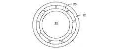
図5に示すように、投影システムPLの最終要素と基板Wの間のスペース11に浸漬液が閉じ込められる。液閉込めシステムは、スペース11を画定する内面を実現する隔壁要素12を備える。浸漬液が入口/出口13を通ってスペース11に供給され、そして、ガス入口15とガス/浸漬液出口14の間のガスの流れ16を使用して、隔壁要素12の底面と基板Wの間に無接触封止が形成される。 As shown in FIG. 5, the immersion liquid is confined in the
浸漬リソグラフィの問題は、スペース11の浸漬液中に泡が存在することである。このスペースの泡の存在は、装置の像形成品質に有害な影響を及ぼすことがある。特に問題のある泡の根源は、基板Wの縁にあることがある。基板の縁の像が形成されるとき、基板の縁の1つがスペース11の下に存在するような位置に、基板は動かされる。基板Wの縁と基板が位置付けされている基板テーブルWTの間のギャップ110をできるだけ小さくし、かつ基板Wと基板テーブルWTの上面が同一平面であることを保証するように、対策が講じられることがある。しかし、基板Wの大きさと基板Wの取扱い易さとのための公差のために、小さなギャップ110がほとんど常に存在している。このギャップの問題は、ガス(例えば、空気)がギャップに閉じ込められることがあり、そして、浸漬液を含むスペース11の下を基板Wの縁が動くとき、メニスカスとの相互作用によって、及び/又はギャップから自由に浮き出る泡によって、泡がギャップ110から浸漬液中に解放されることがある。この問題は、また、例えば透過像センサなどのセンサのような、浸漬液を通して像が形成される必要のある基板テーブル上の他の部品にも存在することがある。本発明の実施例は、基板Wの縁に関して説明されるが、スペース11又は隔壁要素12がそれの縁の上を通過する任意の他の物体、例えば閉じ板のまわりの溝に等しく応用することができる(この閉じ板は、例えば基板交換中に投影システムの下に浸漬液を閉じ込めるために使用される)。 The problem with immersion lithography is the presence of bubbles in the immersion liquid in
基板Wの縁が泡の供給源であるという問題は、特に、平面図の面積に関して浸漬液で満たされたスペース11が基板Wよりも小さい液閉込めシステムと関係がある。そのような液閉込めシステムは、全ての図に示され、基板の局部だけに浸漬液を供給する。 The problem that the edge of the substrate W is a source of bubbles is particularly relevant for liquid confinement systems in which the
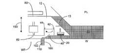
2005年4月5日に出願された米国特許出願第11/098,615号に記載された種類の隔壁要素12に関して、図6に泡の影響を軽減するか又は最小限にする1つの方法が示されている。これによって、この出願はその全体が組み込まれる。この型の隔壁要素12は、2004年8月19日に出願された米国特許出願第10/921,348号に開示されたような液除去デバイス20を、その隔壁要素12の底面の半径方向で一番内側の縁部のところから備えている。これによって、この出願はその全体が組み込まれる。液体除去デバイス20の半径方向外側の方に凹部40が設けられ、この凹部40は、入口42から出口44(半径方向外側の方)にガスの流れが生じるように、入口42を通って雰囲気に接続され、出口44を介して低圧源に接続されている。凹部40の半径方向外側の方にガス・ナイフ60がある。隔壁要素12の底面のこれら3つの部品の配列は、2005年1月14日に出願された米国特許出願第60/643,626号に詳細に説明されている。これによって、この出願は全体が組み込まれる。浸漬液は、スペースを画定している隔壁要素12の内側の壁にある入口13を通ってスペースに供給される。出口80は、隔壁要素12の内面の上部近くに設けられ、それで、スペースの液のレベルが所望の高さよりも大きいとき、浸漬液は出口80を通ってスペースから流れ出ることができる。入口13及び出口80は、ただ模式的に図示されている。図2〜4に示されるものを含んでどんな型の入口/出口も使用することができるが、所望のものは、米国特許出願第60/643,626号に図示されている。 For a
明らかになるように、投影ビームPBを用いた基板W又はセンサのような他の物体の像形成中に、基板テーブルWTは、投影システムPLに対して動かされる。隔壁要素12は、一般に投影システムPLに対して静止した状態に保たれるが、基板W、基板テーブルWT又はセンサの上面までの距離を実質的に一定に維持するために、Z方向に動かすことができ、さらにRx及びRy軸のまわりに傾斜させることができる。理解されることであろうが、基板テーブルWTは、全ての部分の像が形成されるようにX及びY方向に基板Wを移動し、また像形成中に、基板Wの上面の局部トポグラフィ変化の責任を取るために、基板WをZ方向で上下に動かし、さらにRx及びRy軸について基板Wを傾斜させる。制御装置は、隔壁要素12の高さを基板Wに対して実質的に一定に維持するために、隔壁要素12の位置を制御する。そのような配列が、ヨーロッパ特許出願第EP−A−1,477,856号及び2004年5月13日に出願された米国特許出願第10/844,575号に開示されている。これによって、これらの出願の両方はその全体が組み込まれる。本発明の実施例では、基板Wの縁100と基板テーブルWTの縁102の間のギャップ110から泡の現れる機会を減少させるために、この制御装置は、隔壁要素12にさらなる動きを与えるように構成されている。同じ制御装置又は異なる制御装置で、浸漬液の供給及び/又は隔壁要素12へのガスの供給を制御することができる。 As will become apparent, the substrate table WT is moved relative to the projection system PL during imaging of the substrate W or other object such as a sensor using the projection beam PB. The
そのような動きの第1の可能な型を図6に示し、図6で、矢印150は、隔壁要素12又はスペース11がギャップ110の上か、又は近くにあるとき、又はギャップ110が近づきつつあるとき、制御装置が隔壁要素12の追加の動きをZ方向に引き起こすことを示している。 A first possible type of such movement is shown in FIG. 6, in which an
実施例では、隔壁要素12は、浸漬液がギャップ110に押し込まれるように、通常下げられるよりもさらに基板Wの方に下げられる。この動きに続いて、隔壁要素12を元の位置に戻すか、又は隔壁要素12を通常ある場所よりも上の位置に動かす上向きの動きが行われる。この繰り返しは、矢印150で示されるように隔壁要素12がZ方向で振動するように繰り返されてもよいが、これは通常必要でなく、通常は、隔壁要素12が縁を横切る度に1サイクルが適切である。すなわち、隔壁要素12は、約1.5Hzであるチップ走査周波数と同じ周波数で振動し、そしてチップ配置に依存して行ごとに1から8回振動し、行走査周波数は約0.1から0.5Hzである。この振動は、基板テーブルWTの動きと同期をとられるとき、必ずしも周期的である必要はない。一般に、隔壁要素12は、基板Wの上約100μmに位置付けされている。これがいわゆる「浮上高さ」であり、これは、ほぼ75μmから1mmの範囲であってよい。隔壁要素12の低下の動きは、実施例では、通常の浮上高さから、基板から30μmから50μm以下までである。繰り返しの速度は、基板Wの走査速度及びギャップ110の幅に関係している。一般に、Z方向での隔壁要素の繰り返し周期は、500mm/sの基板W走査速度の場合、約0.5sである。繰り返し周期の一般的な範囲は0.1から50msである。 In an embodiment, the
上記の説明では、隔壁要素12は、Z方向で一様に上下に動くと仮定した(すなわち、Rx及びRy方向の回転無しに)。しかし、必ずしもこうではなく、ギャップ110の上か又は近くの位置の隔壁要素12の部分に最大の動きが起こり、かつギャップから遠い部分は僅かに動くだけであるように、すなわち隔壁要素12の傾斜が引き起こされるように、Z方向の隔壁要素12の動きを整えることができる。 In the above description, it was assumed that the
実施例では、隔壁要素12が基板又は基板テーブル又はセンサから遠ざかるように、Z方向の隔壁要素12の上向きの動きだけが、隔壁要素12の通常動作に必要な任意の他の動きに追加される。そして、このことは、スペース11の縁部で凹部40のガスの流れによる影響を受ける隔壁要素12の下の浸漬液のメニスカス160を安定化するように作用する。これは、一様な動きによって、又は上述のように傾斜させることによって、達成することができる。上向きの動きは、ガス・ナイフからのガスの速度を減少させ、それによってメニスカスに対する外乱を減少させ、さらにまた、ギャップが毛管作用によっていっそう容易に満たされるようにメニスカスに対する粘性力を減少させる。 In an embodiment, only upward movement of the
図7は、基板W又は他の物体と基板テーブルWTの間のギャップ110がスペース11に近づく(すなわち、基板テーブルWTが、図7に示す方向200に動く)ときに、スペースの浸漬液に生じる水平方向の圧力勾配によって浸漬液がギャップ110に押し込まれるように、隔壁要素12が、近づくギャップ110の方に傾斜される実施例を示している。その結果、ギャップ110は、隔壁要素12が傾斜されないままである場合に存在するよりも高い圧力のかかった浸漬液で満たされるようになる。ギャップ110がスペース11の近傍か又は下にある間、又はギャップが隔壁要素12の近くか又は下にある間、隔壁要素12のこの傾斜を維持することができ、又はギャップ110がその位置から遠ざかる前に傾斜を取り除くことができる。傾斜は、一度に加えることができ、又はギャップ110が隔壁要素12又はスペース11に近づくときに次第に大きくすることができる。 FIG. 7 illustrates the space immersion liquid as the
像形成品質の低下を軽減することのできる更なる又は代替えの方法は、隔壁要素12及び/又はスペース11がギャップ110の上か、又は近くに位置付けされたとき、ギャップ110の近傍での浸漬液の流れが装置の光軸から離れる方向で強くなること、すなわち、流れが発生するか、既存の流れが増大すること、を保証することである。投影システムの光軸から離れる浸漬液の流れ、又は浸漬液の流れの増大は、この流れによってギャップ110で形成された泡がスペース11に入るのを妨げられるか、又は減らされることを保証する。この仕事のために別個の制御装置を使用することができ、又は、浸漬液の流れの方向を通常制御するために使用されるものと同じ制御装置を使用することができる。この流れは、浸漬液の圧力を変えることによって間接的に発生させることができる。 A further or alternative way of reducing the degradation of the imaging quality is that immersion liquid in the vicinity of the
2005年4月5日に出願された米国特許出願第11/098,615号は、スペース11を横切る浸漬液の流れをどのようにして高めることができるかを開示し、この開示は、特に、隔壁要素12の内面のほんの一部のまわりだけに入力を設け、また、この入口の一部に対してスペース11の他方の側に位置する隔壁要素12のほんの一部のまわりだけに出力を設けることに関している。このシステムは、本発明の実施例で使用することができる。 US patent application Ser. No. 11 / 098,615, filed on Apr. 5, 2005, discloses how the flow of immersion liquid across the
図8の実施例では、追加の入口300が、液除去デバイス20と凹部40の間に位置する隔壁要素12の底面に設けられている。入口300は、入口を出る浸漬液を少なくとも部分的に半径方向外側の方に向けるように角度を付けられ、かつ/又は形作られており、入口の半径方向外側の方の位置(例えば、ギャップ110)で浸漬液中に形成された泡が入口の半径方向内側の方に、投影ビームが放射されるスペース11の中心部に向かって動くのを実質的妨げるか、又は減らすために、出てくる浸漬液が有効であるような具合になっている。実施例では、入口300は、スペース11のまわりにループになって設けられているが、隔壁要素12の一部のまわりにだけに設けてもよい。例えば、米国特許出願第11/098,615号の隔壁要素に出口が設けられた周囲のほんの一部と同様な周囲のほんの一部のまわりにだけに設けてもよい。 In the embodiment of FIG. 8, an additional inlet 300 is provided on the bottom surface of the
また、制御装置を使用して、隔壁要素の周囲のまわりの入口/出口を流れる浸漬液の流量を変えることによって、流れの所望の方向を実現することができる。これは、例えば、隔壁要素12の周囲のまわりに液体除去デバイス20を、個々に制御可能な個々の個別セグメントとして設けることによって達成することができる。これを図9に示す。同様にして、様々な圧力及び/又は浸漬液の流量及び/又はそれらの入口/出口を通るガスを制御することによって、上述のように、浸漬液の流れの方向を制御して所望の液流れを達成することができるように、入口13、凹部40及びガス・ナイフ60を隔壁要素12の周囲のまわりにセグメントで設けることもできる。流れの所望の増大は、例えばギャップ110の上の領域で抽出を大きくすることで達成することができる。 Also, using the controller, the desired direction of flow can be achieved by varying the flow rate of immersion liquid flowing through the inlet / outlet around the periphery of the septum element. This can be achieved, for example, by providing the
スペースにおける浸漬液の流れの方向が隔壁要素に対して実質的に一定であるような型の隔壁要素である場合(例えば、米国特許出願第11/098,615号又は2005年1月14日に出願された米国特許出願第60/643,608号で開示されたもの)、光軸に対して実質的に垂直な平面内で光軸のまわりに隔壁要素を回転させて、ギャップ110の近傍での浸漬液の流れが常に半径方向外側の方に向いていること、すなわち装置の光軸から離れる方向であることを保証することが可能である。これを図10a及び10bに示す。ここで、基板Wの縁に近い基板Wの異なる位置で浸漬液の流れの方向400が半径方向外側の方に向いていることを保証するように、隔壁要素12が回転されていることを理解することができる。 When the partition element is of a type such that the direction of immersion liquid flow in the space is substantially constant relative to the partition element (eg, US patent application Ser. No. 11 / 098,615 or January 14, 2005). In the vicinity of the
実施例では、ガス・ナイフがギャップ110の上に位置付けされたとき、ガス・ナイフ60を通るガスの流れを減少させるか、又はオフにするのが有利であることがある。その理由は、流出ガスの高い圧力でギャップ110の浸漬液が吹き飛ばされ、それによって、浸漬液の泡の形成が起こるからである。さらに、ガス・ナイフを出るガスの速度を減少することは、毛管力を受ける浸漬液でギャップ110を満たすのを妨げないために有効である。ガス・ナイフ60を通るガスの流れを完全に中断しないでただその流れを減少することが有利である。ガス・ナイフを通るガスの流れを減少させる方法を好都合に実現する1つの方法は、ガス・ナイフを出るガスが通過する最終くびれを、互いに相対的に動くことができる同心のリング又は要素の垂直壁で形成することである。この方法で、ギャップの幅を変えることができ、それによって、ガスの流出速度は、速度をゼロに減少することなしに変えることができる。 In an embodiment, when the gas knife is positioned over the
更なる又は代替えの実施例では、基板Wの全体を完全に取り囲む隔壁要素12が設けられる。したがって、基板Wの像形成中に隔壁要素12と基板テーブルWTの間に封止が形成され、基板Wは、隔壁要素12による完全なループで取り囲まれている。この実施例では、隔壁要素12は、基板Wの上面の像を形成するために必要とされる範囲で、投影システムPLに対してXY平面内で可動である。この実施例では、ギャップ110に対する浸漬液の相対的な動きは、泡の形成を起こさせないように大きな範囲で行われない。また、隔壁要素12は、例えばセンサの像を形成する必要があるとき、基板Wの全体にわたって動かすことができる。 In further or alternative embodiments,
上述の実施例の全ては、任意の組合せで、又は個々に使用することができる。 All of the above embodiments can be used in any combination or individually.
ヨーロッパ特許出願公表第1420300号及び米国特許出願公表第2004−0136494号では、ツインすなわちデュアル・ステージ浸漬リソグラフィ装置の概念が開示されている。これによって各出願は、参照してその全体が組み込まれる。そのような装置は、基板を支持するテーブルを2個備えている。高さ測定は、浸漬液のない状態で第1の位置のテーブルで行われ、そして露光は、浸漬液が存在している第2の位置のテーブルで行われる。もしくは、装置にただ1つのテーブルだけがある。 European Patent Application Publication No. 1420300 and US Patent Application Publication No. 2004-0136494 disclose the concept of a twin or dual stage immersion lithography apparatus. Each application is hereby incorporated by reference in its entirety. Such an apparatus comprises two tables that support the substrate. The height measurement is performed on the first position table without immersion liquid, and the exposure is performed on the second position table where immersion liquid is present. Or there is only one table in the device.
この明細書では、ICの製造におけるリソグラフィ装置の使用に特に言及することがあるが、本明細書で説明したリソグラフィ装置には、集積光システム、磁気ドメイン・メモリの誘導及び検出パターン、フラットパネル・ディスプレイ、液晶ディスプレイ(LCD)、薄膜磁気ヘッド、その他の製造のような他の用途があることは理解すべきである。当業者は理解するであろうが、そのような他の用途の背景では、本明細書での用語「ウェーハ」又は「チップ」の使用はどれも、より一般的な用語「基板」又は「目標部分」とそれぞれ同義であると考えることができる。本明細書で参照する基板は、例えばトラック(一般にレジスト層を基板に塗布し、さらに露光されたレジストを現像するルール)、計測ツール、及び/又は検査ツールで、露光前又は後に処理することができる。応用可能な場合、本明細書の開示は、そのような及び他の基板処理ツールに応用することができる。さらに、基板は、例えば多層ICを作るために一度より多く処理することができるので、本明細書で使用される基板という用語は、複数の処理された層をすでに含む基板も意味することができる。 Although this specification may specifically refer to the use of lithographic apparatus in the manufacture of ICs, the lithographic apparatus described herein includes integrated optical systems, magnetic domain memory guidance and detection patterns, flat panel It should be understood that there are other applications such as displays, liquid crystal displays (LCDs), thin film magnetic heads, and others. As those skilled in the art will appreciate, in the context of such other applications, any use of the terms “wafer” or “chip” herein is more generic than the terms “substrate” or “target”. It can be considered to be synonymous with “part”. The substrate referred to herein may be processed before or after exposure, for example, with a track (generally a rule for applying a resist layer to the substrate and then developing the exposed resist), metrology tool, and / or inspection tool. it can. Where applicable, the disclosure herein may be applied to such and other substrate processing tools. Further, since the substrate can be processed more than once, for example to make a multi-layer IC, the term substrate as used herein can also mean a substrate that already contains multiple processed layers. .
本明細書で使用される用語「放射」及び「ビーム」は、紫外線(UV)放射(例えば、約365、248、193、157又は126nmの波長を有する)を含んだ、全ての種類の電磁放射を包含する。 As used herein, the terms “radiation” and “beam” include all types of electromagnetic radiation, including ultraviolet (UV) radiation (eg, having a wavelength of about 365, 248, 193, 157 or 126 nm). Is included.
用語「レンズ」は、背景が許す場合、屈折光学部品及び反射光学部品を含んだ様々な型の光学部品のどれか1つ又は組合せを意味することができる。 The term “lens” can mean any one or combination of various types of optical components, including refractive and reflective optical components, as the background allows.
本発明の特定の実施例を上で説明したが、理解されるであろうが、本発明は説明されたのと違ったやり方で実施することができる。例えば、本発明は、先に開示されたような方法を記述する機械可読命令の1つ又は複数のシーケンスを含んだコンピュータ・プログラム、又は格納されたそのようなコンピュータ・プログラムを有するデータ記憶媒体(例えば、半導体メモリ、磁気ディスク又は光ディスク)の形を取ることができる。 While specific embodiments of the invention have been described above, it will be appreciated that the invention can be practiced otherwise than as described. For example, the present invention provides a computer program that includes one or more sequences of machine-readable instructions that describe a method as previously disclosed, or a data storage medium having such a computer program stored ( For example, it can take the form of a semiconductor memory, magnetic disk or optical disk.
本発明の1つ又は複数の実施例は、特に、上で言及したそんな型だけではなく、また浸漬液が槽の形で供給されようと基板の局所表面領域だけに供給されようと、どんな浸漬リソグラフィ装置にも応用することができる。本明細書で意図したような液体供給システムは広く解釈されるべきである。特定の実施例では、液体供給システムは、投影システムと基板及び/又は基板テーブルとの間のスペースに液体を供給する機構か、又は構造の組合せであってもよい。液体供給システムは、1つ又は複数の構造、1つ又は複数の液体入口、1つ又は複数のガス入口、1つ又は複数のガス出口、及び/又は液体をスペースに供給する1つ又は複数の液体出口の組合せを備えることができる。実施例では、スペースの表面は、基板及び/又は基板テーブルの一部であることがあり、又はスペースの表面は、基板及び/又は基板テーブルの表面を完全に覆っていることがあり、又はスペースが基板及び/又は基板テーブルを包むことがある。場合によっては、液体供給システムは、液体の位置、量、質、形、流量、又は任意の他の特徴を制御する1つ又は複数の要素をさらに含むことができる。 One or more embodiments of the present invention are not limited to such molds, particularly those types referred to above, and any immersion, whether the immersion liquid is supplied in the form of a bath or only to a local surface area of the substrate. It can also be applied to a lithographic apparatus. A liquid supply system as intended herein should be broadly construed. In certain embodiments, the liquid supply system may be a mechanism or combination of structures that supplies liquid to the space between the projection system and the substrate and / or substrate table. The liquid supply system includes one or more structures, one or more liquid inlets, one or more gas inlets, one or more gas outlets, and / or one or more for supplying liquid to a space. A combination of liquid outlets can be provided. In embodiments, the surface of the space may be part of the substrate and / or substrate table, or the surface of the space may completely cover the surface of the substrate and / or substrate table, or the space May enclose the substrate and / or the substrate table. In some cases, the liquid supply system may further include one or more elements that control the position, quantity, quality, shape, flow rate, or any other characteristic of the liquid.
上述の説明は、例示であり制限しない意図である。したがって、当業者には明らかになることであろうが、以下に述べる特許請求の範囲の範囲から逸脱することなしに、説明したような本発明に対して修正を行うことができる。 The above description is intended to be illustrative and not limiting. Thus, it will be apparent to one skilled in the art that modifications may be made to the invention as described without departing from the scope of the claims set out below.
SO 放射源
PS 投影システム
MA パターン形成デバイス(マスク、レチクル)
MT マスク・テーブル
B 放射ビーム
W 基板(ウェーハ)
WT 基板テーブル
PL 投影システム
11 スペース
12 隔壁要素
13 浸漬液入口/出口
14 ガス/浸漬液出口
15 ガス入口
16 ガスの流れ(無接触封止)
20 液体除去デバイス
40 凹部
42 ガス入口
44 ガス出口
60 ガス・ナイフ
80 浸漬液出口
100 基板の縁
102 基板テーブルの縁
110 ギャップ
160 メニスカス
300 浸漬液入口SO radiation source PS projection system MA patterning device (mask, reticle)
MT Mask table B Radiation beam W Substrate (wafer)
WT substrate table
20
Claims (13)
Translated fromJapanese前記隔壁要素、前記スペース、又はその両方が前記基板又は他の物体の縁の上か又は近くに位置付けされたとき、前記縁の近傍で前記装置の光軸から離れる方向に液体の流れを引き起こすか又は大きくするように構成された制御装置を備え、
前記制御装置は、前記縁と基板テーブルの縁との間のギャップに毛管力で液体を満たすのを実質的に妨げないために、前記縁の上か又は近くの位置で、前記隔壁要素の底面に位置付けされたガス・ナイフを出るガスの速度を減少させるように構成されている、リソグラフィ投影装置。A lithographic projection apparatus configured to project a radiation beam onto a substrate or other object through a liquid confined in space by a septum element,
Does the septum element, the space, or both cause liquid flow in the direction away from the optical axis of the device in the vicinity of the edge when positioned on or near the edge of the substrate or other object? Or a control device configured to be enlarged,
The control device is located at or near the edge of the septum element so that it does not substantially impede the filling of the gap between the edge and the edge of the substrate table with capillary forces. A lithographic projection apparatus, wherein the lithographic projection apparatusis configured to reduce the velocity of gas exiting a gas knife positioned on the surface.
隔壁要素によってスペースに閉じ込められた液体を通してパターン形成された放射ビームを基板に投影するステップと、
前記隔壁要素、前記スペース、又は両方が前記基板の縁の上か又は近くに位置付けされるように前記基板を動かすステップと、
前記縁の近傍で前記装置の光軸から離れる方向に液体の流れを引き起こすか又は大きくするステップと、
前記縁と基板テーブルの縁との間のギャップに毛管力で液体を満たすのを実質的に妨げないために、前記縁の上か又は近くの位置で、前記隔壁要素の底面に位置付けされたガス・ナイフを出るガスの速度を減少させるステップと、を含む方法。A device manufacturing method using a lithographic projection apparatus, comprising:
Projecting a patterned beam of radiation onto a substrate through a liquid confined in space by a septum element;
Moving the substrate such that the septum element, the space, or both are positioned on or near the edge of the substrate;
Causing or increasing the flow of liquid in the direction away from the optical axis of the device in the vicinity of the edge;
Gas positioned on the bottom surface of the septum element at or near the edge so as not to substantially impede liquid filling with capillary forces into the gap between the edge and the edge of the substrate table. Reducing the velocity of the gas exiting the knife .
Applications Claiming Priority (2)
| Application Number | Priority Date | Filing Date | Title |
|---|---|---|---|
| US11/167,563 | 2005-06-28 | ||
| US11/167,563US7468779B2 (en) | 2005-06-28 | 2005-06-28 | Lithographic apparatus and device manufacturing method |
Related Parent Applications (1)
| Application Number | Title | Priority Date | Filing Date |
|---|---|---|---|
| JP2009293786ADivisionJP5219993B2 (en) | 2005-06-28 | 2009-12-25 | Lithographic apparatus |
Publications (2)
| Publication Number | Publication Date |
|---|---|
| JP2012147039A JP2012147039A (en) | 2012-08-02 |
| JP5349644B2true JP5349644B2 (en) | 2013-11-20 |
Family
ID=37566909
Family Applications (3)
| Application Number | Title | Priority Date | Filing Date |
|---|---|---|---|
| JP2006176023AExpired - Fee RelatedJP4566952B2 (en) | 2005-06-28 | 2006-06-27 | Lithographic apparatus and device manufacturing method |
| JP2009293786AExpired - Fee RelatedJP5219993B2 (en) | 2005-06-28 | 2009-12-25 | Lithographic apparatus |
| JP2012109711AActiveJP5349644B2 (en) | 2005-06-28 | 2012-05-11 | Lithographic apparatus and device manufacturing method |
Family Applications Before (2)
| Application Number | Title | Priority Date | Filing Date |
|---|---|---|---|
| JP2006176023AExpired - Fee RelatedJP4566952B2 (en) | 2005-06-28 | 2006-06-27 | Lithographic apparatus and device manufacturing method |
| JP2009293786AExpired - Fee RelatedJP5219993B2 (en) | 2005-06-28 | 2009-12-25 | Lithographic apparatus |
Country Status (2)
| Country | Link |
|---|---|
| US (3) | US7468779B2 (en) |
| JP (3) | JP4566952B2 (en) |
Families Citing this family (19)
| Publication number | Priority date | Publication date | Assignee | Title |
|---|---|---|---|---|
| US20040031167A1 (en)* | 2002-06-13 | 2004-02-19 | Stein Nathan D. | Single wafer method and apparatus for drying semiconductor substrates using an inert gas air-knife |
| KR101178755B1 (en)* | 2004-06-10 | 2012-08-31 | 가부시키가이샤 니콘 엔지니어링 | Exposure equipment, exposure method and device manufacturing method |
| US7468779B2 (en)* | 2005-06-28 | 2008-12-23 | Asml Netherlands B.V. | Lithographic apparatus and device manufacturing method |
| JP4752374B2 (en)* | 2005-07-27 | 2011-08-17 | 株式会社ニコン | Exposure apparatus, liquid holding method, and device manufacturing method |
| JP4125315B2 (en)* | 2005-10-11 | 2008-07-30 | キヤノン株式会社 | Exposure apparatus and device manufacturing method |
| US7864292B2 (en) | 2005-11-16 | 2011-01-04 | Asml Netherlands B.V. | Lithographic apparatus and device manufacturing method |
| US7804577B2 (en) | 2005-11-16 | 2010-09-28 | Asml Netherlands B.V. | Lithographic apparatus |
| US7633073B2 (en) | 2005-11-23 | 2009-12-15 | Asml Netherlands B.V. | Lithographic apparatus and device manufacturing method |
| US7692765B2 (en)* | 2007-02-21 | 2010-04-06 | Asml Netherlands B.V. | Lithographic apparatus and method of removing liquid |
| US8514365B2 (en)* | 2007-06-01 | 2013-08-20 | Asml Netherlands B.V. | Lithographic apparatus and device manufacturing method |
| NL2002983A1 (en)* | 2008-06-26 | 2009-12-29 | Asml Netherlands Bv | A lithographic apparatus and a method of operating the lithographic apparatus. |
| SG159467A1 (en)* | 2008-09-02 | 2010-03-30 | Asml Netherlands Bv | Fluid handling structure, lithographic apparatus and device manufacturing method |
| NL2003362A (en)* | 2008-10-16 | 2010-04-19 | Asml Netherlands Bv | Lithographic apparatus and device manufacturing method. |
| EP2196857A3 (en)* | 2008-12-09 | 2010-07-21 | ASML Netherlands BV | Lithographic apparatus and device manufacturing method |
| NL2008183A (en)* | 2011-02-25 | 2012-08-28 | Asml Netherlands Bv | A lithographic apparatus, a method of controlling the apparatus and a device manufacturing method. |
| NL2008979A (en)* | 2011-07-11 | 2013-01-14 | Asml Netherlands Bv | A fluid handling structure, a lithographic apparatus and a device manufacturing method. |
| NL2009472A (en)* | 2011-10-24 | 2013-04-25 | Asml Netherlands Bv | A fluid handling structure, a lithographic apparatus and a device manufacturing method. |
| JP6241384B2 (en) | 2014-07-17 | 2017-12-06 | ウシオ電機株式会社 | Self-assembled monolayer patterning device, light irradiation device, and self-assembled monolayer patterning method |
| EP4062233A1 (en) | 2019-11-18 | 2022-09-28 | ASML Netherlands B.V. | A fluid handling system, method and lithographic apparatus |
Family Cites Families (130)
| Publication number | Priority date | Publication date | Assignee | Title |
|---|---|---|---|---|
| DE224448C (en) | ||||
| DE221563C (en) | ||||
| DE242880C (en) | ||||
| DE206607C (en) | ||||
| GB1242527A (en) | 1967-10-20 | 1971-08-11 | Kodak Ltd | Optical instruments |
| US3573975A (en) | 1968-07-10 | 1971-04-06 | Ibm | Photochemical fabrication process |
| ATE1462T1 (en) | 1979-07-27 | 1982-08-15 | Werner W. Dr. Tabarelli | OPTICAL LITHOGRAPHY PROCESS AND DEVICE FOR COPYING A PATTERN ONTO A SEMICONDUCTOR DISC. |
| FR2474708B1 (en) | 1980-01-24 | 1987-02-20 | Dme | HIGH-RESOLUTION MICROPHOTOLITHOGRAPHY PROCESS |
| JPS5754317A (en) | 1980-09-19 | 1982-03-31 | Hitachi Ltd | Method and device for forming pattern |
| US4346164A (en) | 1980-10-06 | 1982-08-24 | Werner Tabarelli | Photolithographic method for the manufacture of integrated circuits |
| US4509852A (en) | 1980-10-06 | 1985-04-09 | Werner Tabarelli | Apparatus for the photolithographic manufacture of integrated circuit elements |
| US4390273A (en) | 1981-02-17 | 1983-06-28 | Censor Patent-Und Versuchsanstalt | Projection mask as well as a method and apparatus for the embedding thereof and projection printing system |
| JPS57153433A (en) | 1981-03-18 | 1982-09-22 | Hitachi Ltd | Manufacturing device for semiconductor |
| JPS58202448A (en) | 1982-05-21 | 1983-11-25 | Hitachi Ltd | exposure equipment |
| DD206607A1 (en) | 1982-06-16 | 1984-02-01 | Mikroelektronik Zt Forsch Tech | METHOD AND DEVICE FOR ELIMINATING INTERFERENCE EFFECTS |
| DD242880A1 (en) | 1983-01-31 | 1987-02-11 | Kuch Karl Heinz | DEVICE FOR PHOTOLITHOGRAPHIC STRUCTURAL TRANSMISSION |
| DD221563A1 (en) | 1983-09-14 | 1985-04-24 | Mikroelektronik Zt Forsch Tech | IMMERSIONS OBJECTIVE FOR THE STEP-BY-STEP PROJECTION IMAGING OF A MASK STRUCTURE |
| DD224448A1 (en) | 1984-03-01 | 1985-07-03 | Zeiss Jena Veb Carl | DEVICE FOR PHOTOLITHOGRAPHIC STRUCTURAL TRANSMISSION |
| JPS6265326A (en) | 1985-09-18 | 1987-03-24 | Hitachi Ltd | Exposure device |
| JPS62121417A (en) | 1985-11-22 | 1987-06-02 | Hitachi Ltd | Immersion objective lens device |
| JPS63157419A (en) | 1986-12-22 | 1988-06-30 | Toshiba Corp | Fine pattern transfer apparatus |
| US5040020A (en) | 1988-03-31 | 1991-08-13 | Cornell Research Foundation, Inc. | Self-aligned, high resolution resonant dielectric lithography |
| JPH03209479A (en) | 1989-09-06 | 1991-09-12 | Sanee Giken Kk | Exposure method |
| US5121256A (en) | 1991-03-14 | 1992-06-09 | The Board Of Trustees Of The Leland Stanford Junior University | Lithography system employing a solid immersion lens |
| JPH04305915A (en) | 1991-04-02 | 1992-10-28 | Nikon Corp | Adhesion type exposure device |
| JPH04305917A (en) | 1991-04-02 | 1992-10-28 | Nikon Corp | Close-contact exposure equipment |
| JPH06124873A (en) | 1992-10-09 | 1994-05-06 | Canon Inc | Immersion projection exposure system |
| JP2753930B2 (en) | 1992-11-27 | 1998-05-20 | キヤノン株式会社 | Immersion type projection exposure equipment |
| JP2520833B2 (en) | 1992-12-21 | 1996-07-31 | 東京エレクトロン株式会社 | Immersion type liquid treatment device |
| JPH07220990A (en) | 1994-01-28 | 1995-08-18 | Hitachi Ltd | Pattern forming method and exposure apparatus thereof |
| US6104687A (en) | 1996-08-26 | 2000-08-15 | Digital Papyrus Corporation | Method and apparatus for coupling an optical lens to a disk through a coupling medium having a relatively high index of refraction |
| US5825043A (en) | 1996-10-07 | 1998-10-20 | Nikon Precision Inc. | Focusing and tilting adjustment system for lithography aligner, manufacturing apparatus or inspection apparatus |
| JP3612920B2 (en) | 1997-02-14 | 2005-01-26 | ソニー株式会社 | Exposure apparatus for producing an optical recording medium master |
| JPH10255319A (en) | 1997-03-12 | 1998-09-25 | Hitachi Maxell Ltd | Master exposure apparatus and method |
| JP3747566B2 (en) | 1997-04-23 | 2006-02-22 | 株式会社ニコン | Immersion exposure equipment |
| JP3817836B2 (en) | 1997-06-10 | 2006-09-06 | 株式会社ニコン | EXPOSURE APPARATUS, ITS MANUFACTURING METHOD, EXPOSURE METHOD, AND DEVICE MANUFACTURING METHOD |
| US5900354A (en) | 1997-07-03 | 1999-05-04 | Batchelder; John Samuel | Method for optical inspection and lithography |
| JPH11176727A (en) | 1997-12-11 | 1999-07-02 | Nikon Corp | Projection exposure equipment |
| EP1039511A4 (en) | 1997-12-12 | 2005-03-02 | Nikon Corp | Projection exposure method and projection aligner |
| WO1999049504A1 (en) | 1998-03-26 | 1999-09-30 | Nikon Corporation | Projection exposure method and system |
| JP2000058436A (en) | 1998-08-11 | 2000-02-25 | Nikon Corp | Projection exposure apparatus and exposure method |
| TWI242111B (en) | 1999-04-19 | 2005-10-21 | Asml Netherlands Bv | Gas bearings for use in vacuum chambers and their application in lithographic projection apparatus |
| JP4504479B2 (en) | 1999-09-21 | 2010-07-14 | オリンパス株式会社 | Immersion objective lens for microscope |
| TW591653B (en) | 2000-08-08 | 2004-06-11 | Koninkl Philips Electronics Nv | Method of manufacturing an optically scannable information carrier |
| US20020163629A1 (en) | 2001-05-07 | 2002-11-07 | Michael Switkes | Methods and apparatus employing an index matching medium |
| US6600547B2 (en) | 2001-09-24 | 2003-07-29 | Nikon Corporation | Sliding seal |
| US6897941B2 (en) | 2001-11-07 | 2005-05-24 | Applied Materials, Inc. | Optical spot grid array printer |
| DE10229818A1 (en) | 2002-06-28 | 2004-01-15 | Carl Zeiss Smt Ag | Focus detection method and imaging system with focus detection system |
| US6788477B2 (en) | 2002-10-22 | 2004-09-07 | Taiwan Semiconductor Manufacturing Co., Ltd. | Apparatus for method for immersion lithography |
| EP1420300B1 (en) | 2002-11-12 | 2015-07-29 | ASML Netherlands B.V. | Lithographic apparatus and device manufacturing method |
| CN101470360B (en) | 2002-11-12 | 2013-07-24 | Asml荷兰有限公司 | Immersion lithographic apparatus and device manufacturing method |
| EP1420298B1 (en) | 2002-11-12 | 2013-02-20 | ASML Netherlands B.V. | Lithographic apparatus |
| CN100568101C (en) | 2002-11-12 | 2009-12-09 | Asml荷兰有限公司 | Photolithography apparatus and device manufacturing method |
| KR100585476B1 (en)* | 2002-11-12 | 2006-06-07 | 에이에스엠엘 네델란즈 비.브이. | Lithographic Apparatus and Device Manufacturing Method |
| SG121822A1 (en) | 2002-11-12 | 2006-05-26 | Asml Netherlands Bv | Lithographic apparatus and device manufacturing method |
| DE60335595D1 (en) | 2002-11-12 | 2011-02-17 | Asml Netherlands Bv | Immersion lithographic apparatus and method of making a device |
| SG131766A1 (en) | 2002-11-18 | 2007-05-28 | Asml Netherlands Bv | Lithographic apparatus and device manufacturing method |
| KR20120127755A (en) | 2002-12-10 | 2012-11-23 | 가부시키가이샤 니콘 | Exposure apparatus and method for manufacturing device |
| WO2004053950A1 (en) | 2002-12-10 | 2004-06-24 | Nikon Corporation | Exposure apparatus and method for manufacturing device |
| WO2004053955A1 (en)* | 2002-12-10 | 2004-06-24 | Nikon Corporation | Exposure system and device producing method |
| KR101101737B1 (en) | 2002-12-10 | 2012-01-05 | 가부시키가이샤 니콘 | Exposure apparatus, exposure method and method for manufacturing device |
| KR20050085026A (en) | 2002-12-10 | 2005-08-29 | 가부시키가이샤 니콘 | Optical device and projection exposure apparatus using such optical device |
| WO2004053951A1 (en) | 2002-12-10 | 2004-06-24 | Nikon Corporation | Exposure method, exposure apparatus and method for manufacturing device |
| EP1571694A4 (en) | 2002-12-10 | 2008-10-15 | Nikon Corp | Exposure apparatus and method for manufacturing device |
| AU2003289272A1 (en) | 2002-12-10 | 2004-06-30 | Nikon Corporation | Surface position detection apparatus, exposure method, and device porducing method |
| JP4352874B2 (en) | 2002-12-10 | 2009-10-28 | 株式会社ニコン | Exposure apparatus and device manufacturing method |
| JP4232449B2 (en) | 2002-12-10 | 2009-03-04 | 株式会社ニコン | Exposure method, exposure apparatus, and device manufacturing method |
| DE10257766A1 (en) | 2002-12-10 | 2004-07-15 | Carl Zeiss Smt Ag | Method for setting a desired optical property of a projection lens and microlithographic projection exposure system |
| US7242455B2 (en) | 2002-12-10 | 2007-07-10 | Nikon Corporation | Exposure apparatus and method for producing device |
| AU2003289237A1 (en) | 2002-12-10 | 2004-06-30 | Nikon Corporation | Exposure apparatus and method for manufacturing device |
| EP1573730B1 (en) | 2002-12-13 | 2009-02-25 | Koninklijke Philips Electronics N.V. | Liquid removal in a method and device for irradiating spots on a layer |
| EP1584089B1 (en) | 2002-12-19 | 2006-08-02 | Koninklijke Philips Electronics N.V. | Method and device for irradiating spots on a layer |
| US7514699B2 (en) | 2002-12-19 | 2009-04-07 | Koninklijke Philips Electronics N.V. | Method and device for irradiating spots on a layer |
| WO2004093159A2 (en) | 2003-04-09 | 2004-10-28 | Nikon Corporation | Immersion lithography fluid control system |
| WO2004090633A2 (en) | 2003-04-10 | 2004-10-21 | Nikon Corporation | An electro-osmotic element for an immersion lithography apparatus |
| EP2950147B1 (en) | 2003-04-10 | 2017-04-26 | Nikon Corporation | Environmental system including vaccum scavenge for an immersion lithography apparatus |
| EP3352010A1 (en) | 2003-04-10 | 2018-07-25 | Nikon Corporation | Run-off path to collect liquid for an immersion lithography apparatus |
| EP3062152B1 (en) | 2003-04-10 | 2017-12-20 | Nikon Corporation | Environmental system including vaccum scavenge for an immersion lithography apparatus |
| JP4582089B2 (en) | 2003-04-11 | 2010-11-17 | 株式会社ニコン | Liquid jet recovery system for immersion lithography |
| KR101225884B1 (en) | 2003-04-11 | 2013-01-28 | 가부시키가이샤 니콘 | Apparatus and method for maintaining immersion fluid in the gap under the projection lens during wafer exchange in an immersion lithography machine |
| CN101825847B (en) | 2003-04-11 | 2013-10-16 | 株式会社尼康 | Cleanup method for optics in immersion lithography |
| JP4428115B2 (en)* | 2003-04-11 | 2010-03-10 | 株式会社ニコン | Immersion lithography system |
| SG194246A1 (en) | 2003-04-17 | 2013-11-29 | Nikon Corp | Optical arrangement of autofocus elements for use with immersion lithography |
| EP2282233A1 (en) | 2003-05-13 | 2011-02-09 | ASML Netherlands BV | Lithographic apparatus |
| TWI295414B (en)* | 2003-05-13 | 2008-04-01 | Asml Netherlands Bv | Lithographic apparatus and device manufacturing method |
| US7274472B2 (en) | 2003-05-28 | 2007-09-25 | Timbre Technologies, Inc. | Resolution enhanced optical metrology |
| DE10324477A1 (en)* | 2003-05-30 | 2004-12-30 | Carl Zeiss Smt Ag | Microlithographic projection exposure system |
| EP2261741A3 (en) | 2003-06-11 | 2011-05-25 | ASML Netherlands B.V. | Lithographic apparatus and device manufacturing method |
| US6867844B2 (en) | 2003-06-19 | 2005-03-15 | Asml Holding N.V. | Immersion photolithography system and method using microchannel nozzles |
| JP4343597B2 (en) | 2003-06-25 | 2009-10-14 | キヤノン株式会社 | Exposure apparatus and device manufacturing method |
| JP2005019616A (en) | 2003-06-25 | 2005-01-20 | Canon Inc | Immersion exposure equipment |
| JP3862678B2 (en) | 2003-06-27 | 2006-12-27 | キヤノン株式会社 | Exposure apparatus and device manufacturing method |
| EP1498778A1 (en) | 2003-06-27 | 2005-01-19 | ASML Netherlands B.V. | Lithographic apparatus and device manufacturing method |
| EP3179309A1 (en) | 2003-07-08 | 2017-06-14 | Nikon Corporation | Wafer table for immersion lithography |
| SG109000A1 (en) | 2003-07-16 | 2005-02-28 | Asml Netherlands Bv | Lithographic apparatus and device manufacturing method |
| US6954256B2 (en) | 2003-08-29 | 2005-10-11 | Asml Netherlands B.V. | Gradient immersion lithography |
| US7070915B2 (en) | 2003-08-29 | 2006-07-04 | Tokyo Electron Limited | Method and system for drying a substrate |
| EP3223053A1 (en) | 2003-09-03 | 2017-09-27 | Nikon Corporation | Apparatus and method for providing fluid for immersion lithography |
| JP4378136B2 (en) | 2003-09-04 | 2009-12-02 | キヤノン株式会社 | Exposure apparatus and device manufacturing method |
| JP3870182B2 (en) | 2003-09-09 | 2007-01-17 | キヤノン株式会社 | Exposure apparatus and device manufacturing method |
| EP1519230A1 (en)* | 2003-09-29 | 2005-03-30 | ASML Netherlands B.V. | Lithographic apparatus and device manufacturing method |
| JP4513299B2 (en)* | 2003-10-02 | 2010-07-28 | 株式会社ニコン | Exposure apparatus, exposure method, and device manufacturing method |
| JP2005159322A (en) | 2003-10-31 | 2005-06-16 | Nikon Corp | Surface plate, stage apparatus, exposure apparatus and exposure method |
| JP2005327975A (en)* | 2004-05-17 | 2005-11-24 | Matsushita Electric Ind Co Ltd | Semiconductor manufacturing apparatus and pattern forming method |
| JP2005175016A (en) | 2003-12-08 | 2005-06-30 | Canon Inc | Substrate holding apparatus, exposure apparatus using the same, and device manufacturing method |
| JP2005175034A (en) | 2003-12-09 | 2005-06-30 | Canon Inc | Exposure equipment |
| US7589818B2 (en) | 2003-12-23 | 2009-09-15 | Asml Netherlands B.V. | Lithographic apparatus, alignment apparatus, device manufacturing method, and a method of converting an apparatus |
| US7394521B2 (en)* | 2003-12-23 | 2008-07-01 | Asml Netherlands B.V. | Lithographic apparatus and device manufacturing method |
| JP2005191381A (en) | 2003-12-26 | 2005-07-14 | Canon Inc | Exposure method and apparatus |
| JP2005191393A (en) | 2003-12-26 | 2005-07-14 | Canon Inc | Exposure method and apparatus |
| JP4429023B2 (en) | 2004-01-07 | 2010-03-10 | キヤノン株式会社 | Exposure apparatus and device manufacturing method |
| JP4018647B2 (en) | 2004-02-09 | 2007-12-05 | キヤノン株式会社 | Projection exposure apparatus and device manufacturing method |
| JP4220423B2 (en)* | 2004-03-24 | 2009-02-04 | 株式会社東芝 | Resist pattern forming method |
| JP4510494B2 (en) | 2004-03-29 | 2010-07-21 | キヤノン株式会社 | Exposure equipment |
| JP2005286068A (en) | 2004-03-29 | 2005-10-13 | Canon Inc | Exposure apparatus and method |
| US7379159B2 (en)* | 2004-05-03 | 2008-05-27 | Asml Netherlands B.V. | Lithographic apparatus and device manufacturing method |
| US7486381B2 (en) | 2004-05-21 | 2009-02-03 | Asml Netherlands B.V. | Lithographic apparatus and device manufacturing method |
| US7304718B2 (en) | 2004-08-17 | 2007-12-04 | Asml Netherlands B.V. | Lithographic apparatus and device manufacturing method |
| US7701550B2 (en)* | 2004-08-19 | 2010-04-20 | Asml Netherlands B.V. | Lithographic apparatus and device manufacturing method |
| JP4852951B2 (en)* | 2004-09-17 | 2012-01-11 | 株式会社ニコン | Exposure apparatus, exposure method, and device manufacturing method |
| DE602006012746D1 (en)* | 2005-01-14 | 2010-04-22 | Asml Netherlands Bv | Lithographic apparatus and manufacturing method |
| JP4591093B2 (en)* | 2005-01-18 | 2010-12-01 | Jsr株式会社 | Scanning exposure method |
| JP2006270057A (en)* | 2005-02-28 | 2006-10-05 | Canon Inc | Exposure equipment |
| JP5040646B2 (en)* | 2005-03-23 | 2012-10-03 | 株式会社ニコン | Exposure apparatus, exposure method, and device manufacturing method |
| US7330238B2 (en) | 2005-03-28 | 2008-02-12 | Asml Netherlands, B.V. | Lithographic apparatus, immersion projection apparatus and device manufacturing method |
| US7411654B2 (en)* | 2005-04-05 | 2008-08-12 | Asml Netherlands B.V. | Lithographic apparatus and device manufacturing method |
| US7433016B2 (en) | 2005-05-03 | 2008-10-07 | Asml Netherlands B.V. | Lithographic apparatus and device manufacturing method |
| US7474379B2 (en)* | 2005-06-28 | 2009-01-06 | Asml Netherlands B.V. | Lithographic apparatus and device manufacturing method |
| US7468779B2 (en)* | 2005-06-28 | 2008-12-23 | Asml Netherlands B.V. | Lithographic apparatus and device manufacturing method |
| JP4374042B2 (en)* | 2007-07-09 | 2009-12-02 | 株式会社東芝 | Manufacturing method of semiconductor device |
- 2005
- 2005-06-28USUS11/167,563patent/US7468779B2/ennot_activeExpired - Fee Related
- 2006
- 2006-06-27JPJP2006176023Apatent/JP4566952B2/ennot_activeExpired - Fee Related
- 2008
- 2008-11-17USUS12/292,329patent/US7929112B2/ennot_activeExpired - Fee Related
- 2009
- 2009-12-25JPJP2009293786Apatent/JP5219993B2/ennot_activeExpired - Fee Related
- 2011
- 2011-04-11USUS13/083,966patent/US8687168B2/ennot_activeExpired - Fee Related
- 2012
- 2012-05-11JPJP2012109711Apatent/JP5349644B2/enactiveActive
Also Published As
| Publication number | Publication date |
|---|---|
| US8687168B2 (en) | 2014-04-01 |
| US20090073408A1 (en) | 2009-03-19 |
| JP2010114455A (en) | 2010-05-20 |
| JP2012147039A (en) | 2012-08-02 |
| US7468779B2 (en) | 2008-12-23 |
| JP5219993B2 (en) | 2013-06-26 |
| US20110188015A1 (en) | 2011-08-04 |
| JP4566952B2 (en) | 2010-10-20 |
| US20060290908A1 (en) | 2006-12-28 |
| JP2007013150A (en) | 2007-01-18 |
| US7929112B2 (en) | 2011-04-19 |
Similar Documents
| Publication | Publication Date | Title |
|---|---|---|
| JP5349644B2 (en) | Lithographic apparatus and device manufacturing method | |
| KR100855337B1 (en) | Lithographic apparatus and device manufacturing method | |
| US8004654B2 (en) | Lithographic apparatus and device manufacturing method | |
| JP4728382B2 (en) | Lithographic apparatus and device manufacturing method | |
| JP5345996B2 (en) | Lithographic apparatus and device manufacturing method | |
| JP5286431B2 (en) | Lithographic apparatus | |
| JP2012074745A (en) | Lithographic apparatus and device manufacturing method | |
| JP2010219545A (en) | Lithographic apparatus, and device manufacturing method | |
| JP5412399B2 (en) | Lithographic apparatus and device manufacturing method | |
| KR100729243B1 (en) | Lithographic Apparatus and Device Manufacturing Method | |
| JP5155277B2 (en) | Lithographic apparatus and device manufacturing method | |
| JP4450782B2 (en) | Lithographic apparatus, device manufacturing method, and computer program product |
Legal Events
| Date | Code | Title | Description |
|---|---|---|---|
| A521 | Request for written amendment filed | Free format text:JAPANESE INTERMEDIATE CODE: A523 Effective date:20120511 | |
| A621 | Written request for application examination | Free format text:JAPANESE INTERMEDIATE CODE: A621 Effective date:20120511 | |
| A977 | Report on retrieval | Free format text:JAPANESE INTERMEDIATE CODE: A971007 Effective date:20130726 | |
| TRDD | Decision of grant or rejection written | ||
| A01 | Written decision to grant a patent or to grant a registration (utility model) | Free format text:JAPANESE INTERMEDIATE CODE: A01 Effective date:20130730 | |
| A61 | First payment of annual fees (during grant procedure) | Free format text:JAPANESE INTERMEDIATE CODE: A61 Effective date:20130820 | |
| R150 | Certificate of patent or registration of utility model | Free format text:JAPANESE INTERMEDIATE CODE: R150 Ref document number:5349644 Country of ref document:JP Free format text:JAPANESE INTERMEDIATE CODE: R150 | |
| R250 | Receipt of annual fees | Free format text:JAPANESE INTERMEDIATE CODE: R250 | |
| R250 | Receipt of annual fees | Free format text:JAPANESE INTERMEDIATE CODE: R250 | |
| R250 | Receipt of annual fees | Free format text:JAPANESE INTERMEDIATE CODE: R250 | |
| R250 | Receipt of annual fees | Free format text:JAPANESE INTERMEDIATE CODE: R250 | |
| R250 | Receipt of annual fees | Free format text:JAPANESE INTERMEDIATE CODE: R250 | |
| R250 | Receipt of annual fees | Free format text:JAPANESE INTERMEDIATE CODE: R250 | |
| R250 | Receipt of annual fees | Free format text:JAPANESE INTERMEDIATE CODE: R250 | |
| R250 | Receipt of annual fees | Free format text:JAPANESE INTERMEDIATE CODE: R250 | |
| R250 | Receipt of annual fees | Free format text:JAPANESE INTERMEDIATE CODE: R250 | |
| R250 | Receipt of annual fees | Free format text:JAPANESE INTERMEDIATE CODE: R250 |