JP5347063B2 - Treatment device - Google Patents
Treatment deviceDownload PDFInfo
- Publication number
- JP5347063B2 JP5347063B2JP2012506834AJP2012506834AJP5347063B2JP 5347063 B2JP5347063 B2JP 5347063B2JP 2012506834 AJP2012506834 AJP 2012506834AJP 2012506834 AJP2012506834 AJP 2012506834AJP 5347063 B2JP5347063 B2JP 5347063B2
- Authority
- JP
- Japan
- Prior art keywords
- treatment
- temperature
- cavitation
- ultrasonic
- unit
- Prior art date
- Legal status (The legal status is an assumption and is not a legal conclusion. Google has not performed a legal analysis and makes no representation as to the accuracy of the status listed.)
- Expired - Fee Related
Links
Images


Classifications
- A—HUMAN NECESSITIES
- A61—MEDICAL OR VETERINARY SCIENCE; HYGIENE
- A61B—DIAGNOSIS; SURGERY; IDENTIFICATION
- A61B17/00—Surgical instruments, devices or methods
- A61B17/32—Surgical cutting instruments
- A61B17/320068—Surgical cutting instruments using mechanical vibrations, e.g. ultrasonic
- A61B17/320092—Surgical cutting instruments using mechanical vibrations, e.g. ultrasonic with additional movable means for clamping or cutting tissue, e.g. with a pivoting jaw
- A—HUMAN NECESSITIES
- A61—MEDICAL OR VETERINARY SCIENCE; HYGIENE
- A61B—DIAGNOSIS; SURGERY; IDENTIFICATION
- A61B17/00—Surgical instruments, devices or methods
- A61B2017/00017—Electrical control of surgical instruments
- A61B2017/00022—Sensing or detecting at the treatment site
- A61B2017/00084—Temperature
- A—HUMAN NECESSITIES
- A61—MEDICAL OR VETERINARY SCIENCE; HYGIENE
- A61B—DIAGNOSIS; SURGERY; IDENTIFICATION
- A61B17/00—Surgical instruments, devices or methods
- A61B2017/00017—Electrical control of surgical instruments
- A61B2017/00132—Setting operation time of a device
- A—HUMAN NECESSITIES
- A61—MEDICAL OR VETERINARY SCIENCE; HYGIENE
- A61B—DIAGNOSIS; SURGERY; IDENTIFICATION
- A61B17/00—Surgical instruments, devices or methods
- A61B17/22—Implements for squeezing-off ulcers or the like on inner organs of the body; Implements for scraping-out cavities of body organs, e.g. bones; for invasive removal or destruction of calculus using mechanical vibrations; for removing obstructions in blood vessels, not otherwise provided for
- A61B17/22004—Implements for squeezing-off ulcers or the like on inner organs of the body; Implements for scraping-out cavities of body organs, e.g. bones; for invasive removal or destruction of calculus using mechanical vibrations; for removing obstructions in blood vessels, not otherwise provided for using mechanical vibrations, e.g. ultrasonic shock waves
- A61B2017/22005—Effects, e.g. on tissue
- A61B2017/22007—Cavitation or pseudocavitation, i.e. creation of gas bubbles generating a secondary shock wave when collapsing
- A61B2017/22008—Cavitation or pseudocavitation, i.e. creation of gas bubbles generating a secondary shock wave when collapsing used or promoted
- A—HUMAN NECESSITIES
- A61—MEDICAL OR VETERINARY SCIENCE; HYGIENE
- A61B—DIAGNOSIS; SURGERY; IDENTIFICATION
- A61B17/00—Surgical instruments, devices or methods
- A61B17/32—Surgical cutting instruments
- A61B17/320068—Surgical cutting instruments using mechanical vibrations, e.g. ultrasonic
- A61B2017/320084—Irrigation sleeves
Landscapes
- Health & Medical Sciences (AREA)
- Surgery (AREA)
- Engineering & Computer Science (AREA)
- Life Sciences & Earth Sciences (AREA)
- Heart & Thoracic Surgery (AREA)
- Nuclear Medicine, Radiotherapy & Molecular Imaging (AREA)
- Mechanical Engineering (AREA)
- Biomedical Technology (AREA)
- Dentistry (AREA)
- Medical Informatics (AREA)
- Molecular Biology (AREA)
- Animal Behavior & Ethology (AREA)
- General Health & Medical Sciences (AREA)
- Public Health (AREA)
- Veterinary Medicine (AREA)
- Surgical Instruments (AREA)
Abstract
Description
Translated fromJapanese本発明は、キャビテーションを利用して処置を行う処置装置に関する。The present invention relatesto the treatment apparatus for performing treatment by using cavitation.
超音波振動そのもの、または、超音波振動に伴って生じる種々の現象を利用することにより、生体組織に対して処置を行う装置(以降、超音波処置装置と称する)が従来広く知られている。このような装置としては、例えば、日本国特開2008−188160号公報に開示された超音波手術器等がある。 2. Description of the Related Art Conventionally, apparatuses that perform treatment on living tissue by utilizing ultrasonic vibrations themselves or various phenomena that occur along with ultrasonic vibrations (hereinafter referred to as ultrasonic treatment apparatuses) are widely known. As such an apparatus, for example, there is an ultrasonic surgical instrument disclosed in Japanese Patent Laid-Open No. 2008-188160.
一方、超音波処置装置における処置能力は、処置対象の領域におけるキャビテーションの発生状態に大きく依存するものとされている。そのため、超音波処置装置を用いて効率良く処置を行うためには、処置対象の領域において発生するキャビテーションを、処置内容に応じた適切な発生状態とするような制御が肝要となる。On the other hand, the treatment capability in the ultrasonic treatment apparatus is largely dependent on the state of occurrence of cavitation in the region to be treated. Therefore, in order to perform treatment efficiently using the ultrasonic treatment apparatus, it is important to control the cavitation generated in the treatment target region to be in an appropriate generation state according to the treatment content.
しかし、日本国特開2008−188160号公報に記載の技術によれば、処置対象の領域において実際に発生するキャビテーションに基づいて振動子を駆動するための負荷が変動することを検出し、キャビテーションの発生を抑制するようなフィードバック制御を行っている。すなわち、日本国特開2008−188160号公報に記載の技術は、生体組織に対する所定の処置の医学的効果を向上させる目的においてキャビテーションの発生量を積極的に減少させるような制御を単に行っているに過ぎず、キャビテーションの発生量を処置内容に応じて適切に変化させる(増加または減少させる)ような制御とは異なるものと考えられる。However, according to the technique described in Japanese Patent Application Laid-Open No. 2008-188160, it is detected that the load for driving the vibrator fluctuates based on cavitation that actually occurs in the treatment target region, Feedback control is performed to suppress the occurrence. That is, the technique described in Japanese Patent Application Laid-Open No. 2008-188160 simply performs control that actively reduces the amount of cavitation generated for the purpose of improving the medical effect of a predetermined treatment on living tissue. However, this is considered to be different from the control that appropriately changes (increases or decreases) the amount of cavitation generated according to the treatment content.
本発明は、前述した事情に鑑みてなされたものであり、処置対象の領域におけるキャビテーションを適切な発生状態とするような制御を行うことにより、処置能力を安定させることが可能な処置装置を提供することを目的としている。The present invention has been made in view of the above-described circumstances,and provides atreatment apparatus capable of stabilizing treatment ability by performing control so that cavitation in a treatment target region is appropriately generated. The purpose is to do.
本発明の処置装置は、超音波振動子において発生した超音波振動を作用させることにより被検体の処置対象領域の処置を行う処置部と、前記超音波振動子を駆動する駆動部から出力される駆動信号に基づき、前記超音波振動子の共振周波数を除き、かつ、少なくとも該共振周波数のサブハーモニックを含む各周波数における電流または電圧の大きさを検出することにより、前記処置対象領域におけるキャビテーションの発生状態を検出する検出部と、前記検出部の検出結果に基づき、前記処置部の温度、または、前記処置部において発生する熱エネルギーの発生状態を変化させることにより、前記処置対象領域におけるキャビテーションの発生状態を制御する制御部と、を有する。The treatment apparatus of the present invention isoutput from a treatment unit that treats a treatment target region of a subjectby applyingultrasonic vibration generated in the ultrasonic transducer, anda drive unit that drives the ultrasonic transducer. Generation of cavitation in the treatment target region by detecting the magnitude of the current or voltage at each frequency that excludes the resonance frequency of the ultrasonic transducer and includes at least a sub-harmonic of the resonance frequency based on the drive signal a detectorfor detecting acondition-out based on the detection result of the detectingsection,the temperature of the treatment portionor by changing the state of occurrence of heat energy generated in the treatment portion, the cavitation in the treatment target area A control unit for controlling the occurrence state of
以下、図面を参照して本発明の実施例を説明する。 Embodiments of the present invention will be described below with reference to the drawings.
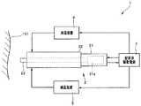
手術システム1は、図1に示すように、処置対象領域101の生体組織に対して超音波振動を作用させることにより処置を行う超音波処置用ハンドピース2と、超音波処置用ハンドピース2を駆動するための超音波駆動信号を供給する超音波駆動電源3と、加温装置4と、減温装置5と、を有している。 As shown in FIG. 1, the
キャビテーション発生部としての機能を備えた超音波処置用ハンドピース2は、術者等により把持される把持部21と、把持部21の先端側に連設されているシース22と、先端部がシース22の先端側から突出しているプローブ23と、を有して構成されている。また、プローブ23の先端部は、処置部としての機能を備えて構成されている。 The
超音波処置用ハンドピース2は、加温装置4の動作に応じてプローブ23の先端部及び/または該先端部の近傍の温度を上昇させる(熱エネルギーの発生を促進させる)ことが可能な加温機能(加温手段)を備えて構成されている。また、超音波処置用ハンドピース2は、減温装置5の動作に応じてプローブ23の先端部及び/または該先端部の近傍の温度を低下させる(熱エネルギーの発生を抑制させる)ことが可能な減温機能(減温手段)を備えて構成されている。さらに、超音波処置用ハンドピース2は、プローブ23の先端部及び/または該先端部の近傍の温度情報を温度信号として出力することが可能な温度情報出力機能(温度情報出力手段)を備えて構成されている。なお、これら3つの機能(手段)を実現するための具体的な構成及び作用については、後程詳述する。The
把持部21の内部には、所定の共振周波数を具備し、プローブ23の基端部と機械的に接続されているとともに、超音波駆動電源3から供給される超音波駆動信号に応じた超音波振動を発生する超音波振動子21aが設けられている。一方、プローブ23は、超音波振動子21aにおいて発生した超音波振動をプローブ23の基端部から先端部へ伝達する。The
すなわち、超音波振動子21aにおいて発生した超音波振動は、プローブ23の中途部を経た後、プローブ23の先端部に伝達される。That is, the ultrasonic vibration generated in the
シース22には、プローブ23の基端部(の一部)及び中途部が内蔵されている。The
超音波駆動電源3は、図2に示すように、所定の共振周波数を具備した超音波振動子21aを駆動するための超音波駆動信号を生成して出力する超音波発振部31と、超音波発振部31から出力される超音波駆動信号の電流及び電圧の大きさを所定の周波数帯域において検出する電流/電圧検出部32と、電流/電圧検出部32による検出結果に対してフィルタ処理を施すフィルタ処理部33と、制御部としての機能を備えたCPU34と、メモリ34aと、インターフェース部35と、を有している。As shown in FIG. 2, the ultrasonic
フィルタ処理部33は、図3に示すように、電流/電圧検出部32における検出結果がそれぞれ入力されるn個のバンドパスフィルタ(図3ではBPFと略記)33a1、33a2、…、33anと、これらn個のバンドパスフィルタの後段に一対一に接続されるn個のスイッチ33b1、33b2、…、33bnと、これらn個の各スイッチの後段に一対一に接続されるn個の検波器33c1、33c2、…、33cnと、これらn個の検波器からの出力信号が入力される積分器33dと、を有して構成されている。 As shown in FIG. 3, the
バンドパスフィルタ33a1、33a2、…、33anは、例えば、通過周波数帯域の一部(端部)が相互に重複するとともに、通過周波数帯域の中心周波数がそれぞれ異なるフィルタとして構成されている。なお、図3においては、バンドパスフィルタ33a1、33a2、…、33anにおける通過周波数帯域の中心周波数をf1、f2、…、fn(但し、f1<f2<…<fnとする)として示している。The band-pass filters 33a1, 33a2,..., 33an are configured, for example, as filters in which part (end portions) of the pass frequency bands overlap with each other and the center frequencies of the pass frequency bands are different from each other. 3, the center frequencies of the pass frequency bands in the band-pass filters 33a1, 33a2,..., 33an are shown as f1, f2,..., Fn (where f1 <f2 <... <Fn).
以降、図4も加えて説明を行う。スイッチ33b1、33b2、…、33bnは、インターフェース部35に設けられたフィルタ切替スイッチ39の切替指示に基づく制御がCPU34において行われることにより、オンまたはオフにそれぞれ切り替えられる。なお、スイッチ33b1、33b2、…、33bnは、フィルタ切替スイッチ39からの切替指示に応じて直接オンまたはオフにそれぞれ切り替えられるように構成されていても良い。Hereinafter, description will be made with reference to FIG. The switches 33
そして、オン状態のスイッチ33b1、33b2、…、33bnを経た周波数成分は、検波器33c1、33c2、…、33cnによりそれぞれ検波された後、積分器33dにより積分処理される。The frequency components that have passed through the switches 33b1, 33b2,..., 33bn in the ON state are detected by the detectors 33c1, 33c2,.
積分器33dは、前述の積分処理の処理結果をキャビテーション検出信号としてCPU34へ出力する。なお、本実施例のフィルタ処理部33は、積分器33dの代わりに積算器を用いて構成されるものであっても良い。また、本実施例においては、前述の積分処理を、積分器33dの代わりにCPU34が行うものであっても良い。The
CPU34は、超音波処置用ハンドピース2の温度情報出力機能(温度情報出力手段)の動作に応じて出力される温度信号と、フィルタ処理部33から出力されるキャビテーション検出信号と、インターフェース部35に設けられた処置速度切替部38の各スイッチの切替状態とに基づき、加温装置4及び減温装置5の動作を必要に応じて適宜制御する。 The
ここで、メモリ34aには、処置速度切替部38においてオンされたスイッチと、該スイッチに対応する適切なキャビテーションの発生状態と、の相関を示す設定データが予め格納されている。 Here, setting data indicating a correlation between a switch turned on in the treatment
具体的には、メモリ34aには、処置速度切替部38において処置速度を低速に設定するスイッチ(後述のスイッチ38a)がオンされた際に、キャビテーションの発生状態を第1のレベルに設定する旨の設定データが格納されている。また、メモリ34aには、処置速度切替部38において処置速度を中速に設定するスイッチ(後述のスイッチ38b)がオンされた際に、キャビテーションの発生状態を第2のレベルに設定する旨の設定データが格納されている。さらに、メモリ34aには、処置速度切替部38において処置速度を高速に設定するスイッチ(後述のスイッチ38c)がオンされた際に、キャビテーションの発生状態を第3のレベルに設定する旨の設定データが格納されている。なお、これらの各設定データ間においては、処置速度の高速化に伴ってキャビテーションが多く発生するように、第1のレベル<第2のレベル<第3のレベルという関係が成り立つものとする。Specifically, in the
そして、キャビテーションの発生状態を第1のレベルに設定する旨の設定データにおいては、プローブ23の先端部及び/または該先端部の近傍の温度を第1の温度とするような設定として、例えば、加温装置4を通常動作させるとともに、減温装置5の動作状態を通常動作よりも高出力動作とする旨の設定がなされている。また、キャビテーションの発生状態を第2のレベルに設定する旨の設定データにおいては、プローブ23の先端部及び/または該先端部の近傍の温度を第2の温度とするような設定として、例えば、加温装置4及び減温装置5をいずれも通常動作させる旨の設定がなされている。さらに、キャビテーションの発生状態を第3のレベルに設定する旨の設定データにおいては、プローブ23の先端部及び/または該先端部の近傍の温度を第3の温度とするような設定として、例えば、加温装置4の動作状態を通常動作よりも高出力動作とするとともに、減温装置5を通常動作させる旨の設定がなされている。なお、これらの各設定においては、第1の温度<第2の温度<第3の温度という関係が成り立つものとする。In the setting data for setting the occurrence state of cavitation to the first level, for example, the temperature at the tip of the
すなわち、CPU34は、メモリ34aに格納された各設定データを(例えば超音波駆動電源3の電源が投入された直後に)予め読み込んでおくとともに、メモリ34aから読み込んだ該各設定データを参照しながら、超音波処置用ハンドピース2の温度情報出力機能(温度情報出力手段)の動作に応じて出力される温度信号と、フィルタ処理部33から出力されるキャビテーション検出信号と、インターフェース部35に設けられた処置速度切替部38の各スイッチの切替状態とに基づく動作制御を加温装置4及び減温装置5に対して適宜行う。 In other words, the
CPU34は、インターフェース部35に設けられた処置速度切替部38の各スイッチの切替状態に基づき、インターフェース部35に設けられたインジケータ37aの表示態様を変化させるための第1の表示制御信号を出力する。 The
CPU34は、フィルタ処理部33から出力されるキャビテーション検出信号に基づき、インターフェース部35に設けられたインジケータ37bの表示態様を変化させるための第2の表示制御信号を随時出力する。Based on the cavitation detection signal output from the
CPU34は、インターフェース部35に設けられた超音波振動切替スイッチ36の切替状態に基づき、駆動部としての機能を備えた超音波発振部31の動作状態をオンまたはオフに切り替えるための制御を行う。Based on the switching state of the ultrasonic
CPU34は、インターフェース部35に設けられたフィルタ切替スイッチ39の切替指示に基づき、フィルタ処理部33のスイッチ33b1、33b2、…、33bnをそれぞれオンまたはオフに切り替えるための制御を行う。The
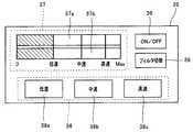
インターフェース部35は、図4に示すように、術者等の操作に応じて超音波振動のオン/オフを切り替え可能な超音波振動切替スイッチ36と、キャビテーションの発生状態の設定値及び測定値に関する情報を視覚的に示す情報提示部37と、処置対象領域101に対する処置速度を術者等の操作に応じて切り替え可能な処置速度切替部38と、フィルタ処理部33のフィルタ処理において使用されるフィルタを術者等の操作に応じて切り替え可能なフィルタ切替スイッチ39と、を有している。また、前述したインターフェース部35の各部は、例えば、超音波駆動電源3のフロントパネルに設けられている。As shown in FIG. 4, the
情報提示部37は、キャビテーションの発生状態の設定値を視覚的に示すインジケータ37aと、キャビテーションの発生状態の測定値を視覚的に示すインジケータ37bと、を備えている。 The
処置速度切替部38は、処置対象領域101に対する処置速度を低速に設定する旨の指示が可能なスイッチ38aと、処置対象領域101に対する処置速度を中速に設定する旨の指示が可能なスイッチ38bと、処置対象領域101に対する処置速度を高速に設定する旨の指示が可能なスイッチ38cと、を備えている。 The treatment
インジケータ37aは、CPU34からの第1の表示制御信号の出力状態に応じて自身の表示態様を変化させる。具体的には、インジケータ37aは、スイッチ38aがオンされている場合には、例えば(図4に示すように)、左端の目盛り「0」から右端の目盛り「Max」までのうち、「0」から「低速」までに相当する部分を一様または略一様に着色するような表示態様とする。また、インジケータ37aは、スイッチ38bがオンされている場合には、例えば、左端の目盛り「0」から右端の目盛り「Max」までのうち、「0」から「中速」までに相当する部分を一様または略一様に着色するような表示態様とする。さらに、インジケータ37aは、スイッチ38cがオンされている場合には、例えば、左端の目盛り「0」から右端の目盛り「Max」までのうち、「0」から「高速」までに相当する部分を一様または略一様に着色するような表示態様とする。 The
インジケータ37bは、CPU34からの第2の表示制御信号の出力状態に応じて自身の表示態様をリアルタイムに変化させる。具体的には、インジケータ37bは、左端の目盛り「0」から右端の目盛り「Max」までのうち、「0」から前述のキャビテーション検出信号のレベルに応じた部分までを一様または略一様に着色するような表示態様とする。例えば、前述のキャビテーション検出信号のレベルが「低速」に相当するものであるとして第2の表示制御信号が出力された場合のインジケータ37bの表示態様は、図4に示すようなものとなる。 The
なお、インジケータ37a及び37bは、LCDパネル上に画像表示されるものであっても良く、または、LED等の発光部材を用いて構成されるものであっても良い。(インジケータ37a及び37bがLED等の発光部材を用いて構成されている場合、着色の有無の代わりに、点灯の有無によりキャビテーションの発生状態の設定値及び測定値に関する情報を表示することができる。)
加温装置4は、超音波駆動電源3の制御に基づき、超音波処置用ハンドピース2の加温機能(加温手段)を動作させることができるように構成されている。具体的には、加温装置4は、超音波駆動電源3の制御に基づき、プローブ23の先端部及び/または該先端部の近傍の温度を上昇及び/または安定させるように出力を変化させることが可能な、例えばDC可変電源を有して構成されている。The
The
減温装置5は、超音波駆動電源3の制御に基づき、超音波処置用ハンドピース2の減温機能(減温手段)を動作させることができるように構成されている。具体的には、減温装置5は、超音波駆動電源3の制御に基づき、プローブ23の先端部及び/または該先端部の近傍へ供給される冷媒の供給量を変化させることが可能な、例えばポンプ及び冷媒タンクを有して構成されている。なお、減温装置5から供給される冷媒は、冷却液または冷却ガス等のいずれであっても良い。 The
なお、本実施例の温度調整部は、加温装置4及び減温装置5を具備して構成されているものとする。また、本実施例の熱エネルギー調整部は、加温装置4及び減温装置5を具備して構成されているものとする。 In addition, the temperature adjustment part of a present Example shall be comprised including the
ここで、本実施例の手術システム1の作用等について説明を行う。 Here, the operation and the like of the
まず、術者は、把持部21を把持しつつ、プローブ23の先端部を処置対象領域101に接近させる操作を行う。また、このような操作に前後して、術者は、超音波振動切替スイッチ36をオフからオンに切り替えることにより、プローブ23の先端部における超音波振動を開始させる。なお、以降においては、プローブ23の先端部における超音波振動の出力レベル(超音波発振部31から出力される超音波駆動信号の出力レベル)が一定のレベルに維持されたまま処置が行われているものとして説明を行う。 First, the surgeon performs an operation of bringing the distal end portion of the
次に、術者は、例えば、処置対象領域101に対する処置速度を設定するために、処置速度切替部38に設けられた各スイッチのうち、いずれか1つのスイッチをオフからオンに切り替える。 Next, for example, in order to set a treatment speed for the
そして、以上までの操作等が行われることにより、処置対象領域101においてキャビテーションが発生し始め、処置対象領域101の生体組織に対する処置が開始される。Then, by performing the above operations and the like, cavitation starts to occur in the
ここで、加温機能(加温手段)、減温機能(減温手段)、及び、温度情報出力機能(温度情報出力手段)として前述した3つの機能(手段)を超音波処置用ハンドピースにおいて実現するための具体的な構成例について説明を行う。なお、以降の各構成例において、特に詳述していない部分については、超音波処置用ハンドピース2の構成要素として前述したものと同様の構成を有するものであるとして説明を進める。 Here, the three functions (means) described above as the heating function (heating means), the temperature reducing function (temperature reducing means), and the temperature information output function (temperature information output means) are used in the ultrasonic treatment handpiece. A specific configuration example for realizing this will be described. It should be noted that, in each of the following configuration examples, portions not specifically described in detail will be described assuming that they have the same configurations as those described above as the components of the
(第1の構成例)
図5は、超音波処置用ハンドピースの第1の構成例を示す図である。(First configuration example)
FIG. 5 is a diagram illustrating a first configuration example of the ultrasonic treatment handpiece.
図5の超音波処置用ハンドピース2Aは、術者等により把持される図示しない把持部の先端側にシース22Aが連設され、シース22Aの内部に管路24Aが形成されているとともに、該管路24Aの内部にプローブ23Aを挿通することが可能な構成を有している。また、処置部としての機能を備えたプローブ23Aの先端部は、処置対象領域101に対する処置が開始された際には、シース22Aの先端面に設けられた開口部24aから突出するように配置される。 In the
管路24Aの一方の端部は、開口部24aに通じている。また、管路24Aの他方の端部は、減温装置5に通じている。そして、このような構成によれば、減温装置5から超音波処置用ハンドピース2Aの管路24Aへ供給された冷媒が開口部24aを経て放出されるため、開口部24aから突出されたプローブ23Aの先端部、及び、該先端部の近傍の温度を低下させることができる(熱エネルギーの発生を抑制させることができる)。One end of the
一方、シース22Aの先端部には、図示しない把持部に設けられた図示しないハンドル等の操作に応じて開閉動作するジョー25Aが設けられている。On the other hand, a
すなわち、図5に示す超音波処置用ハンドピース2Aにおいては、超音波振動中のプローブ23Aの先端部と、ジョー25Aとの間に処置対象領域101の生体組織を挟み込んで保持することにより、該生体組織に対する処置が施される。That is, in the ultrasonic
ジョー25Aのうち、処置対象領域101の生体組織に直接接触する部分には、温度センサ26が設けられている。また、温度センサ26は、シース22Aの内部に挿通される図示しない信号線を介し、超音波駆動電源3のCPU34に接続される。そして、このような構成によれば、温度センサ26は、開口部24aから突出されたプローブ23Aの先端部の近傍の温度情報を取得し、取得した該温度情報を温度信号として超音波駆動電源3のCPU34へ出力することができる。 A temperature sensor 26 is provided in a portion of the jaw 25 </ b> A that directly contacts the living tissue of the
ジョー25Aのうち、温度センサ26に隣接する部分には、発熱素子27Aが設けられている。また、発熱素子27Aは、シース22Aの内部に挿通される図示しない電熱線または信号線を介し、加温装置4に接続されている。そして、このような構成によれば、加温装置4から出力された電圧及び/または電流の大きさに応じて発熱素子27Aが発熱するため、開口部24aから突出されたプローブ23Aの先端部、及び、該先端部の近傍の温度を上昇させることができる(熱エネルギーの発生を促進させることができる)。 A heating element 27 </ b> A is provided in a portion of the jaw 25 </ b> A adjacent to the temperature sensor 26. The
なお、図5に示す超音波処置用ハンドピース2Aにおける減温機能(減温手段)は、前述した構成により実現されるものに限らず、図6に示すようなプローブ23Bを用いて実現されるものであっても良い。 Note that the temperature reduction function (temperature reduction means) in the
プローブ23Bは、例えば図6に示すような管路24Bを内部に具備しているとともに、これ以外の部分についてはプローブ23Aと同様の構成を有している。プローブ23Bに内蔵された管路24Bは、減温装置5から供給された冷媒をプローブ23Bの先端部まで流通させた後、該先端部に達した冷媒を減温装置5へ還流させることが可能な構成を有している。このような構成によれば、減温装置5から管路24Bへ供給された冷媒により、処置部としての機能を備えたプローブ23Bの先端部の温度を内部から低下させることができる(熱エネルギーの発生を内部から抑制させることができる)。 The probe 23B has a conduit 24B as shown in FIG. 6, for example, and has the same configuration as the
(第2の構成例)
図7は、超音波処置用ハンドピースの第2の構成例を示す図である。(Second configuration example)
FIG. 7 is a diagram illustrating a second configuration example of the ultrasonic treatment handpiece.
図7の超音波処置用ハンドピース2Cは、術者等により把持される図示しない把持部の先端側に中空形状のシース22Cが連設されているとともに、シース22Cの中空部にプローブ23Cを挿通することが可能な構成を有している。また、処置部としての機能を備えたプローブ23Cの先端部は、処置対象領域101に対する処置が開始された際には、中空形状のシース22Cの先端側の開口部22cから突出するように配置される。さらに、プローブ23Cの内部には、先端側に開口部24cを有する管路24Cが設けられている。 In the ultrasonic treatment handpiece 2C of FIG. 7, a
開口部24cの内周面において、処置対象領域101の生体組織に接触または近接する位置には、温度センサ26が設けられている。また、温度センサ26は、シース22Cの内部に挿通される図示しない信号線を介し、超音波駆動電源3のCPU34に接続される。そして、このような構成によれば、温度センサ26は、開口部22cから突出されたプローブ23Cの先端部の近傍の温度情報を取得し、取得した該温度情報を温度信号として超音波駆動電源3のCPU34へ出力することができる。 On the inner peripheral surface of the opening 24c, a temperature sensor 26 is provided at a position in contact with or close to the living tissue of the
管路24Cの一方の端部は、開口部24cに通じている。また、管路24Cの他方の端部は、減温装置5に通じている。 One end of the pipe line 24C communicates with the opening 24c. Further, the other end of the conduit 24 </ b> C communicates with the
一方、開口部24cの温度センサ26に近接する位置には、開口部24cの開口面に沿った網目状パターンを有するヒーターパターン27Cが配置されている。また、ヒーターパターン27Cは、プローブ23Cの内部に挿通される図示しない電熱線を介し、加温装置4に接続されている。On the other hand, a
そして、以上に述べたような構成によれば、減温装置5から超音波処置用ハンドピース2Cの管路24Cへ供給された冷媒は、ヒーターパターン27Cを通過した後、開口部24cから放出される。また、以上に述べたような構成によれば、加温装置4から出力された電圧及び/または電流の大きさに応じてヒーターパターン27Cが発熱する。 According to the configuration described above, the refrigerant supplied from the
従って、以上に述べたような構成によれば、ヒーターパターン27Cを通過した冷媒が、(例えば冷媒としての機能を完全に失う程度まで)十分に加熱された状態として開口部24cから放出された場合、開口部22cから突出されたプローブ23Cの先端部、及び、該先端部の近傍の温度を上昇させることができる(熱エネルギーの発生を促進させることができる)。一方、以上に述べたような構成によれば、ヒーターパターン27Cを通過した冷媒が、(例えば冷媒としての機能が維持される程度までしか)十分に加熱されていない状態として開口部24cから放出された場合、開口部22cから突出されたプローブ23Cの先端部、及び、該先端部の近傍の温度を低下させることができる(熱エネルギーの発生を抑制させることができる)。 Therefore, according to the configuration described above, the refrigerant that has passed through the
(第3の構成例)
図8は、超音波処置用ハンドピースの第3の構成例を示す図である。(Third configuration example)
FIG. 8 is a diagram illustrating a third configuration example of the ultrasonic treatment handpiece.
図8の超音波処置用ハンドピース2Dは、術者等により把持される図示しない把持部の先端側にシース22Dが連設されているとともに、シース22Dの内部に管路24Dが形成されている。また、プローブ23Dの先端部は、処置対象領域101に対する処置が開始された際には、シース22Dの先端側の開口部22dから突出するように配置される。さらに、処置部としての機能を備えたプローブ23Dの先端部には、処置対象領域101の生体組織に対して処置を行うための処置部28Dが設けられている。 In the
管路24Dの一方の端部は、開口部22dに通じている。また、管路24Dの他方の端部は、減温装置5に通じている。そして、このような構成によれば、減温装置5から超音波処置用ハンドピース2Dの管路24Dへ供給された冷媒が開口部22dを経て放出されるため、開口部22dから突出された処置部28D、及び、処置部28Dの近傍の温度を低下させることができる(熱エネルギーの発生を抑制させることができる)。One end of the
一方、処置部28Dは、例えば図8に示すように、略平行に配置された2本のアームの先端部の間に略半円状に湾曲された板部材を掛け渡して構成されている。また、前記板部材の湾曲外側の面には、正温度特性(PTC:Positive Temperature Coefficient)を有する部材により形成されたヒーター27Dが設けられている。ヒーター27Dは、プローブ23Dの内部に挿通される図示しない信号線を介し、加温装置4に接続されている。そして、このような構成によれば、加温装置4から出力された電圧及び/または電流の大きさに応じてヒーター27Dが発熱するため、開口部22dから突出された処置部28D、及び、処置部28Dの近傍の温度を上昇させることができる(熱エネルギーの発生を促進させることができる)。 On the other hand, the
また、前述のような構成によれば、ヒーター27Dの抵抗値と処置部28Dの温度とが正の相関を有しつつ変動するため、ヒーター27Dの抵抗値の検出結果を処置部28Dの温度情報とみなすことができる。すなわち、第3の構成例の超音波処置用ハンドピース2Dにおいては、前述の温度情報を備えた温度信号を超音波駆動電源3のCPU34へ出力する構成により、温度情報出力機能(温度情報出力手段)を実現することができる。Further, according to the configuration as described above, since the resistance value of the heater 27D and the temperature of the
続いて、本実施例の手術システム1において行われる制御等に関する説明を行う。なお、以降の説明においては、前述の第1の構成例〜第3の構成例のいずれの構成を採用した場合であっても、同様の制御等が行われることを前提としている。そのため、以降においては、少なくとも前述の第1の構成例〜第3の構成例が包括されるように、図1の超音波処置用ハンドピース2が加温機能(加温手段)、減温機能(減温手段)、及び、温度情報出力機能(温度情報出力手段)の各機能(手段)を具備するものとして説明を進める。 Subsequently, a description will be given of control and the like performed in the
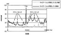
処置対象領域101においてキャビテーションが発生し始め、処置対象領域101の生体組織に対する処置が開始されると、電流/電圧検出部32は、超音波発振部31から出力される超音波駆動信号の電流の大きさを、例えば図9に示すようなものとして検出する。 When cavitation starts to occur in the
図9は、電流/電圧検出部32における超音波駆動信号の電流の大きさの検出結果を、周波数スペクトル分布として示したものである。なお、図9においては、共振周波数fresを47kHzとして設定している。また、図9においては、(比較のために、)キャビテーションが発生していない場合の周波数スペクトル分布を破線により示し、また、キャビテーションが発生している場合の周波数スペクトル分布を実線により示している。 FIG. 9 shows the detection result of the magnitude of the current of the ultrasonic drive signal in the current /
図9に例示した電流の大きさの検出結果によれば、キャビテーションの発生の有無によらずに、共振周波数fresにおいて最も大きいピークが検出されている。 According to the detection result of the current magnitude illustrated in FIG. 9, the largest peak is detected at the resonance frequency fres regardless of the occurrence of cavitation.
また、図9に例示した電流の大きさの検出結果によれば、キャビテーションが発生している場合には、共振周波数fres以外の周波数成分においていくつかの顕著なピークが検出されているとともに、キャビテーションが発生していない場合には、共振周波数fres以外の周波数成分においては顕著なピークが検出されない。Further, according to the detection result of the current magnitude illustrated in FIG. 9, when cavitation occurs, some significant peaks are detected in frequency components other than the resonance frequency fres, and cavitation is detected. In the case where no occurrence occurs, a significant peak is not detected in frequency components other than the resonance frequency fres.
具体的には、図9に示すように、キャビテーションが発生している場合には、キャビテーションが発生していない場合に比べ、共振周波数fresの1/2,1/4等の約数またはこれらの差分の周波数に相当するサブハーモニックのレベルが特に高くなっているとともに、サブハーモニック以外の周波数成分のレベルも略一様に高くなっている。そのため、電流/電圧検出部32における超音波駆動信号の電流の大きさの検出結果のうち、共振周波数fresの近傍を除く周波数帯域の信号レベルを検出することにより、処置対象領域101におけるキャビテーションの発生状態を検出することができる。Specifically, as shown in FIG. 9, when cavitation occurs, a divisor such as 1/2, 1/4, or the like of the resonance frequency fres, or these values, when compared with a case where cavitation does not occur. The level of the sub-harmonic corresponding to the difference frequency is particularly high, and the level of the frequency components other than the sub-harmonic is substantially uniform. Therefore, by detecting the signal level in the frequency band excluding the vicinity of the resonance frequency fres from the detection result of the current of the ultrasonic drive signal in the current /
なお、本実施例の手術システム1においては、超音波駆動信号の電流の大きさの検出結果と、該超音波駆動信号の電圧の大きさの検出結果とが、相互に略同一の傾向を示す。そのため、超音波駆動信号の電流の大きさの検出結果の代わりに、該超音波駆動信号の電圧の大きさの検出結果を用いた場合であっても、以降に述べる処理及び動作を略同様に行うことができる。In the
フィルタ処理部33は、CPU34の制御に基づき、バンドパスフィルタ33a1、33a2、…、33anにおける通過周波数帯域を、例えば、図10、図11または図12に示すもののうちのいずれか1つになるように、スイッチ33b1、33b2、…、33bnをそれぞれ切り替える。 Based on the control of the
図10は、バンドパスフィルタ33a1、33a2、…、33anにおける通過周波数帯域を、低周波側の一部の周波数帯域とするように設定した場合を示している。具体的には、図10は、バンドパスフィルタ33a1、33a2、…、33anにおける通過周波数帯域を、共振周波数fresの1/2のサブハーモニック(約数)を含む周波数帯域とするように設定した場合を示している。 FIG. 10 shows a case where the pass frequency band in the band pass filters 33a1, 33a2,..., 33an is set to be a partial frequency band on the low frequency side. Specifically, FIG. 10 shows a case where the pass frequency band in the band pass filters 33a1, 33a2,..., 33an is set to a frequency band including a sub-harmonic (divisor) of 1/2 of the resonance frequency fres. Is shown.
図11は、バンドパスフィルタ33a1、33a2、…、33anにおける通過周波数帯域を、共振周波数fresの5%程度の周波数から共振周波数fresより5%低い周波数(つまり共振周波数fresの95%の周波数)までに設定した場合を示している。FIG. 11 shows that the pass frequency band in the band pass filters 33a1, 33a2,..., 33an is from about 5% of the resonance frequency fres to a
図12は、バンドパスフィルタ33a1、33a2、…、33anにおける通過周波数帯域を、図11に示す周波数帯域と、共振周波数fresより5%高い周波数から共振周波数fresの2次高調波の周波数(2fres)より5%低い周波数までの周波数帯域と、に設定した場合を示している。FIG. 12 shows the frequency band of the pass frequency band in the band pass filters 33a1, 33a2,..., 33an, and the frequency of the second harmonic of the resonance frequency fres from the frequency band shown in FIG. This shows a case where the frequency band is set to a frequency lower by 5%.
すなわち、バンドパスフィルタ33a1、33a2、…、33anにおける通過周波数帯域は、超音波振動子21aの共振周波数を除き、かつ、少なくとも該共振周波数のサブハーモニックを含むように設定される。That is, the pass frequency band in the band pass filters 33a1, 33a2,..., 33an is set so as to exclude at least the resonance frequency of the
そして、フィルタ処理部33は、オン状態のスイッチ33b1、33b2、…、33bnを経た周波数成分を検波器33c1、33c2、…、33cnにおいてそれぞれ検波し、積分器33dにおいて積分処理した後、この積分処理の処理結果をキャビテーション検出信号としてCPU34へ出力する。 Then, the
ところで、図9に例示した電流の大きさの検出結果によれば、キャビテーションの発生量が多くなるに伴い、前述のサブハーモニックのレベルが高くなるという傾向が現れる。そのため、積分器33dにおける積分処理の処理結果は、バンドパスフィルタ33a1、33a2、…、33anにおける通過周波数帯域が同じであるという条件において、キャビテーションの発生量が多くなるにつれて相対的に大きな値になる一方、キャビテーションの発生量が少なくなるにつれて相対的に小さな値になる。すなわち、本実施例のCPU34は、このような値の変動をキャビテーション検出信号におけるレベルの変動として検出することにより、以降のような処理及び動作を行っている。 By the way, according to the detection result of the current magnitude illustrated in FIG. 9, as the amount of cavitation increases, the above-described subharmonic level tends to increase. Therefore, the processing result of the integration processing in the
CPU34は、スイッチ38cがオンされていることを検出すると、キャビテーションの発生状態が前述の第3のレベルになるように、プローブ23の先端部及び/または該先端部の近傍の温度を前述の第3の温度とする設定を行う。そして、CPU34は、プローブ23の先端部及び/または該先端部の近傍の温度が前述の第3の温度に到達して維持されるとともに、フィルタ処理部33から出力されるキャビテーション検出信号のレベルが前述の第3のレベルに到達して維持されるように、加温装置4の動作状態を通常動作よりも高出力動作にするとともに、減温装置5を通常動作させる制御を行う。このような制御によれば、超音波処置用ハンドピース2の加温機能(加温手段)による温度の上昇が減温機能(減温手段)による温度の低下を上回るため、プローブ23の先端部及び該先端部の近傍の温度が上昇し、処置対象領域101におけるキャビテーションの発生が促進される。その結果、処置対象領域101におけるキャビテーションの発生量が相対的に多くなり、処置対象領域101に対する処置速度を高速にすることができる。 When detecting that the
また、CPU34は、キャビテーションの発生状態を前述の第3のレベルに設定した直後において、インジケータ37aの「0」から「高速」までに相当する部分を一様または略一様に着色させるような第1の表示制御信号をインターフェース部35へ出力する。さらに、CPU34は、フィルタ処理部33から出力されるキャビテーション検出信号のレベルを前述の第3のレベルに到達及び維持させる制御を行っている最中に、インジケータ37bの「0」から該キャビテーション検出信号のレベルに応じた部分までを一様または略一様に着色させるような第2の表示制御信号を随時インターフェース部35へ出力する。そして、インジケータ37aの表示態様が第1の表示制御信号に応じたものとなり、インジケータ37bの表示態様が第2の表示制御信号に応じてリアルタイムに変化することにより、術者等は、現在のキャビテーションの発生状態が高速な処置速度に適した状態となっているか否かを容易に確認することができる。Further, immediately after the cavitation occurrence state is set to the third level, the
CPU34は、スイッチ38aがオンされていることを検出すると、キャビテーションの発生状態が前述の第1のレベルになるように、プローブ23の先端部及び/または該先端部の近傍の温度を前述の第1の温度とする設定を行う。そして、CPU34は、プローブ23の先端部及び/または該先端部の近傍の温度が前述の第1の温度に到達して維持されるとともに、フィルタ処理部33から出力されるキャビテーション検出信号のレベルが前述の第1のレベルに到達して維持されるように、加温装置4を通常動作させるとともに、減温装置5の動作状態を通常動作よりも高出力動作とする制御を行う。このような制御によれば、超音波処置用ハンドピース2の減温機能(減温手段)による温度の低下が加温機能(加温手段)による温度の上昇を上回るため、プローブ23の先端部及び該先端部の近傍の温度が低下し、処置対象領域101におけるキャビテーションの発生が抑制される。その結果、処置対象領域101におけるキャビテーションの発生量が相対的に少なくなり、処置対象領域101に対する処置速度を低速にすることができる。When the
また、CPU34は、キャビテーションの発生状態を前述の第1のレベルに設定した直後において、インジケータ37aの「0」から「低速」までに相当する部分を一様または略一様に着色させるような第1の表示制御信号をインターフェース部35へ出力する。さらに、CPU34は、フィルタ処理部33から出力されるキャビテーション検出信号のレベルを前述の第1のレベルに到達及び維持させる制御を行っている最中に、インジケータ37bの「0」から該キャビテーション検出信号のレベルに応じた部分までを一様または略一様に着色させるような第2の表示制御信号を随時インターフェース部35へ出力する。そして、インジケータ37aの表示態様が第1の表示制御信号に応じたものとなり、インジケータ37bの表示態様が第2の表示制御信号に応じてリアルタイムに変化することにより、術者等は、現在のキャビテーションの発生状態が低速な処置速度に適した状態となっているか否かを容易に確認することができる。Further, immediately after the cavitation occurrence state is set to the first level, the
以上に述べたように、本実施例の手術システム1によれば、処置対象領域101におけるキャビテーションの発生状態(発生量)を、処置対象領域101に対する処置速度に応じた適切なものとすることができる。そのため、本実施例の手術システム1によれば、例えば超音波処置用ハンドピース2のような、(超音波振動に伴って生じる)キャビテーションを利用しながら処置対象領域101に対する処置を行う装置の処置能力を安定させることができる。 As described above, according to the
また、本実施例の手術システム1によれば、プローブ23の先端部における超音波振動の出力レベル(超音波発振部31から出力される超音波駆動信号の出力レベル)を一定のレベルに保ったまま、すなわち、超音波振動子21aにおける超音波振動の振幅を特に変更することなく、処置対象領域101におけるキャビテーションの発生状態(発生量)を変化させることができる。そのため、本実施例の手術システム1によれば、超音波振動子21aに対する制御に伴う負荷を減らすことができ、結果的に、超音波処置用ハンドピース2の耐用期間を延ばすことができる。 Further, according to the
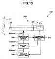
ところで、本実施例は、図1に示す手術システム1に対して適用されるものに限らず、例えば、図13に示す手術システム100に対しても略同様に適用することができる。なお、以降において、手術システム1と同様の構成を有する部分については、適宜説明を省略しつつ説明を行うものとする。 By the way, a present Example is not restricted to what is applied with respect to the
図13の手術システム100は、加温機能(加温手段)、減温機能(減温手段)、及び、温度情報出力機能(温度情報出力手段)の各機能(手段)を、超音波処置用ハンドピースの外部において実現した場合の構成例を示している。具体的には、手術システム100は、図13に示すように、処置対象領域101の生体組織に対して超音波振動を作用させることにより処置を行う超音波処置用ハンドピース200と、超音波処置用ハンドピース200を駆動するための超音波駆動信号を供給する超音波駆動電源300と、ヒーターユニット400と、冷媒供給ユニット500と、温度検出部600と、を有している。 The
超音波処置用ハンドピース200は、加温機能(加温手段)、減温機能(減温手段)、及び、温度情報出力機能(温度情報出力手段)の各機能(手段)を具備していない代わりに、温度検出部600を通過した冷媒をプローブ23の先端部及び/または該先端部の近傍へ流通させるための図示しない管路を内部に具備している。 The
超音波駆動電源300は、超音波駆動電源3と同様の構成を有している。但し、超音波駆動電源300のメモリ34aには、以下のような設定データが書き込まれているものとする。 The ultrasonic
超音波駆動電源300のメモリ34aには、処置速度切替部38においてスイッチ38aがオンされた際に、キャビテーションの発生状態を第1のレベルに設定する旨の設定データが格納されている。また、超音波駆動電源300のメモリ34aには、処置速度切替部38においてスイッチ38bがオンされた際に、キャビテーションの発生状態を第2のレベルに設定する旨の設定データが格納されている。さらに、超音波駆動電源300のメモリ34aには、処置速度切替部38においてスイッチ38cがオンされた際に、キャビテーションの発生状態を第3のレベルに設定する旨の設定データが格納されている。なお、これらの各設定データ間においては、処置速度の高速化に伴ってキャビテーションが多く発生するように、第1のレベル<第2のレベル<第3のレベルという関係が成り立つものとする。 The
キャビテーションの発生状態を第1のレベルに設定する旨の設定データにおいては、超音波処置用ハンドピース200のプローブ23の先端部及び/または該先端部の近傍の温度を第1の温度とするような設定として、例えば、ヒーターユニット400を通常動作させるとともに、冷媒供給ユニット500の動作状態を通常動作よりも高出力動作とする旨の設定がなされている。また、キャビテーションの発生状態を第2のレベルに設定する旨の設定データにおいては、超音波処置用ハンドピース200のプローブ23の先端部及び/または該先端部の近傍の温度を第2の温度とするような設定として、例えば、ヒーターユニット400及び冷媒供給ユニット500をいずれも通常動作させる旨の設定がなされている。さらに、キャビテーションの発生状態を第3のレベルに設定する旨の設定データにおいては、超音波処置用ハンドピース200のプローブ23の先端部及び/または該先端部の近傍の温度を第3の温度とするような設定として、例えば、ヒーターユニット400の動作状態を通常動作よりも高出力動作とするとともに、冷媒供給ユニット500を通常動作させる旨の設定がなされている。なお、これらの各設定においては、第1の温度<第2の温度<第3の温度という関係が成り立つものとする。In the setting data indicating that the cavitation occurrence state is set to the first level, the temperature of the distal end portion of the
そして、超音波駆動電源300のCPU34は、前述の各設定データを(例えば超音波駆動電源300の電源が投入された直後に)予め読み込んでおくとともに、メモリ34aから読み込んだ該各設定データを参照しながら、温度検出部600から出力される温度信号と、フィルタ処理部33から出力されるキャビテーション検出信号と、インターフェース部35に設けられた処置速度切替部38の各スイッチの切替状態とに基づく動作制御をヒーターユニット400及び冷媒供給ユニット500に対して行う。 Then, the
冷媒供給ユニット500は、超音波駆動電源300の制御に応じ、冷却液及び/または冷却ガス等の冷媒を管路へ供給することが可能な構成を有している。具体的には、冷媒供給ユニット500は、超音波駆動電源300の制御に応じて動作するローラーポンプにより、タンクに貯められた冷却水を送り出すような液体冷却タイプとして構成されている。または、冷媒供給ユニット500は、超音波駆動電源300の制御に応じて動作する送気ユニットにより、ボンベに貯められた冷却ガスを送り出すような気体冷却タイプとして構成されている。または、冷媒供給ユニット500は、前述の2種類のタイプを組み合わせた装置として構成されている。The
ヒーターユニット400は、超音波駆動電源300の制御に基づいて発熱することにより、冷媒供給ユニット500から供給される冷媒を温めることが可能な構成を有している。具体的には、ヒーターユニット400は、冷媒供給ユニット500から温度検出部600に至るまでの経路上の管路の少なくとも1箇所に配置されたヒーターと、超音波駆動電源300の制御に応じて各ヒーターを駆動するための駆動電源と、を有して構成されている。 The
温度検出部600は、ヒーターユニット400から超音波処置用ハンドピース200へ至るまでの経路上の管路に設けられている。また、温度検出部600は、ヒーターユニット400を通過して超音波処置用ハンドピース200へ供給される冷媒の温度を検出し、検出結果を温度信号として超音波駆動電源300へ出力する。 The
すなわち、手術システム100の構成によれば、冷媒供給ユニット500から供給された冷媒は、ヒーターユニット400と、温度検出部600と、超音波処置用ハンドピース200の内部の管路と、を順次経た後、プローブ23の先端部及び/または該先端部の近傍へ流れてゆく。 That is, according to the configuration of the
なお、手術システム100によれば、超音波駆動電源300のメモリ34aに書き込まれた各設定データをCPU34が読み込むことにより、手術システム1の説明において述べたものと同様の制御等を行うことができる。そのため、手術システム100において行われる制御等の詳細については、説明を省く。 According to the
そして、本実施例を手術システム100に適用した場合においても、本実施例を手術システム1に適用した場合と略同様の効果を得ることができる。 Even when the present embodiment is applied to the
本発明は、上述した実施例に限定されるものではなく、発明の趣旨を逸脱しない範囲内において種々の変更や応用が可能であることは勿論である。 The present invention is not limited to the above-described embodiments, and it is needless to say that various modifications and applications can be made without departing from the spirit of the invention.
Claims (4)
Translated fromJapanese前記超音波振動子を駆動する駆動部から出力される駆動信号に基づき、前記超音波振動子の共振周波数を除き、かつ、少なくとも該共振周波数のサブハーモニックを含む各周波数における電流または電圧の大きさを検出することにより、前記処置対象領域におけるキャビテーションの発生状態を検出する検出部と、
前記検出部の検出結果に基づき、前記処置部の温度、または、前記処置部において発生する熱エネルギーの発生状態を変化させることにより、前記処置対象領域におけるキャビテーションの発生状態を制御する制御部と、
を有することを特徴とする処置装置。A treatment unit that performs treatment of the treatment target region of the subjectby applyingultrasonic vibration generated in the ultrasonic vibrator ;
Based on the drive signal output from the drive unit that drives the ultrasonic transducer, the magnitude of the current or voltage at each frequency excluding the resonance frequency of the ultrasonic transducer and including at least the sub-harmonic of the resonance frequency Detecting a cavitation occurrence state in the treatment target region by detecting
-Out based on the detection result of the detectingsection,the temperature of the treatment portionor by changing the state of occurrence of heat energy generated in the treatment portion, the control unit for controlling the occurrence of cavitation in the treatment target area When,
A treatment device comprising:
ことを特徴とする請求項1に記載の処置装置。The treatment apparatus according to claim 1.
ことを特徴とする請求項1に記載の処置装置。The treatment apparatus according to claim 1.
ことを特徴とする請求項1に記載の処置装置。The treatment apparatus according to claim 1.
Applications Claiming Priority (1)
| Application Number | Priority Date | Filing Date | Title |
|---|---|---|---|
| PCT/JP2009/066319WO2011030470A1 (en) | 2009-09-11 | 2009-09-11 | Treatment apparatus and operation system |
Publications (2)
| Publication Number | Publication Date |
|---|---|
| JP2013501530A JP2013501530A (en) | 2013-01-17 |
| JP5347063B2true JP5347063B2 (en) | 2013-11-20 |
Family
ID=42035852
Family Applications (1)
| Application Number | Title | Priority Date | Filing Date |
|---|---|---|---|
| JP2012506834AExpired - Fee RelatedJP5347063B2 (en) | 2009-09-11 | 2009-09-11 | Treatment device |
Country Status (4)
| Country | Link |
|---|---|
| US (1) | US8579836B2 (en) |
| JP (1) | JP5347063B2 (en) |
| CN (1) | CN102481156B (en) |
| WO (1) | WO2011030470A1 (en) |
Families Citing this family (3)
| Publication number | Priority date | Publication date | Assignee | Title |
|---|---|---|---|---|
| JP2014000311A (en)* | 2012-06-20 | 2014-01-09 | Olympus Corp | Ultrasonic treatment instrument |
| US10004521B2 (en)* | 2013-11-14 | 2018-06-26 | Gyrus Acmi, Inc. | Feedback dependent lithotripsy energy delivery |
| DE102016001048B4 (en)* | 2016-01-30 | 2024-02-29 | Schölly Fiberoptic GmbH | endoscope |
Family Cites Families (17)
| Publication number | Priority date | Publication date | Assignee | Title |
|---|---|---|---|---|
| US5195959A (en)* | 1991-05-31 | 1993-03-23 | Paul C. Smith | Electrosurgical device with suction and irrigation |
| US5419761A (en) | 1993-08-03 | 1995-05-30 | Misonix, Inc. | Liposuction apparatus and associated method |
| CN1076627C (en)* | 1996-02-14 | 2001-12-26 | 北京中科电气高技术公司 | Efficient ultrasonic fat-reducing slimming machine |
| US6723063B1 (en)* | 1998-06-29 | 2004-04-20 | Ekos Corporation | Sheath for use with an ultrasound element |
| US5989208A (en)* | 1997-05-16 | 1999-11-23 | Nita; Henry | Therapeutic ultrasound system |
| US6758090B2 (en)* | 1998-06-15 | 2004-07-06 | Schlumberger Technology Corporation | Method and apparatus for the detection of bubble point pressure |
| JP3565758B2 (en)* | 2000-03-09 | 2004-09-15 | 株式会社日立製作所 | Sensitizer for tumor treatment |
| JP2003033365A (en)* | 2001-07-23 | 2003-02-04 | Hitachi Ltd | Ultrasound therapy equipment |
| US7771372B2 (en)* | 2003-01-03 | 2010-08-10 | Ekos Corporation | Ultrasonic catheter with axial energy field |
| US7566333B2 (en)* | 2003-08-11 | 2009-07-28 | Electromedical Associates Llc | Electrosurgical device with floating-potential electrode and methods of using the same |
| WO2005074365A2 (en)* | 2004-02-06 | 2005-08-18 | Technion Research And Development Foundation Ltd. | Localized production of microbubbles and control of cavitational and heating effects by use of enhanced ultrasound |
| US7259827B2 (en)* | 2004-07-14 | 2007-08-21 | Asml Netherlands B.V. | Diffuser unit, lithographic apparatus, method for homogenizing a beam of radiation, a device manufacturing method and device manufactured thereby |
| JP4369907B2 (en)* | 2005-07-01 | 2009-11-25 | 株式会社日立製作所 | Sonochemical treatment equipment |
| JP4933911B2 (en) | 2007-02-02 | 2012-05-16 | 学校法人日本医科大学 | Ultrasound surgical device |
| US20080194999A1 (en)* | 2007-02-09 | 2008-08-14 | Norihiro Yamaha | Ultrasonic treatment apparatus and treatment method |
| US9044261B2 (en)* | 2007-07-31 | 2015-06-02 | Ethicon Endo-Surgery, Inc. | Temperature controlled ultrasonic surgical instruments |
| US8100927B2 (en)* | 2007-11-28 | 2012-01-24 | Dadson Manufacturing Corp. | Dermatome with ultrasonic cutting blade |
- 2009
- 2009-09-11JPJP2012506834Apatent/JP5347063B2/ennot_activeExpired - Fee Related
- 2009-09-11WOPCT/JP2009/066319patent/WO2011030470A1/enactiveApplication Filing
- 2009-09-11CNCN200980161393.1Apatent/CN102481156B/ennot_activeExpired - Fee Related
- 2012
- 2012-03-09USUS13/416,651patent/US8579836B2/enactiveActive
Also Published As
| Publication number | Publication date |
|---|---|
| JP2013501530A (en) | 2013-01-17 |
| US8579836B2 (en) | 2013-11-12 |
| CN102481156B (en) | 2015-02-04 |
| US20120172767A1 (en) | 2012-07-05 |
| WO2011030470A1 (en) | 2011-03-17 |
| CN102481156A (en) | 2012-05-30 |
Similar Documents
| Publication | Publication Date | Title |
|---|---|---|
| JP4855541B2 (en) | Ultrasonic surgical apparatus, ultrasonic surgical system including the ultrasonic surgical apparatus, and cavitation using method | |
| JP4950342B2 (en) | Ultrasonic surgical apparatus, ultrasonic surgical system, and cavitation suppression method | |
| US10004526B2 (en) | Ultrasonic dissection system | |
| JP4398493B2 (en) | Surgical treatment device | |
| CN103237512B (en) | devices and techniques for cutting and coagulating tissue | |
| JP3822433B2 (en) | TREATMENT TOOL, TREATMENT TOOL CONTROL DEVICE AND MEDICAL TREATMENT SYSTEM | |
| CN107693108A (en) | Surgical Generators and Surgical Systems | |
| JP2018519919A (en) | Surgical system with user adaptable technique using simultaneous energy modality based on tissue parameters | |
| JP2018519918A (en) | Surgical system with user adaptable technique based on tissue impedance | |
| JP2018531684A (en) | Frequency agile generator for surgical instruments | |
| JP2003010202A (en) | Method for detecting transverse mode vibration in ultrasonic handpiece/blade | |
| JP2005058616A (en) | Control device for medical system and method of control for medical system | |
| JP6001226B1 (en) | Joint surgery system | |
| JP5347063B2 (en) | Treatment device | |
| JPH10225462A (en) | Electric operating device | |
| JP5347064B2 (en) | Treatment apparatus and surgical system | |
| WO2017122345A1 (en) | Energy control device and treatment system | |
| JPWO2018011858A1 (en) | Energy treatment system and energy generator in the energy treatment system | |
| JP4734012B2 (en) | Fever treatment device | |
| JP3699825B2 (en) | Ultrasonic surgical device | |
| JP4455402B2 (en) | Ultrasonic treatment device | |
| JP2002078715A (en) | Ultrasonic surgical operation system | |
| JP2007319697A (en) | Control device for medical system | |
| WO2017094063A1 (en) | Surgery system, surgical instrument, method for controlling surgical instrument, and program for controlling surgical instrument |
Legal Events
| Date | Code | Title | Description |
|---|---|---|---|
| A131 | Notification of reasons for refusal | Free format text:JAPANESE INTERMEDIATE CODE: A131 Effective date:20130521 | |
| A521 | Request for written amendment filed | Free format text:JAPANESE INTERMEDIATE CODE: A523 Effective date:20130624 | |
| TRDD | Decision of grant or rejection written | ||
| A01 | Written decision to grant a patent or to grant a registration (utility model) | Free format text:JAPANESE INTERMEDIATE CODE: A01 Effective date:20130730 | |
| A61 | First payment of annual fees (during grant procedure) | Free format text:JAPANESE INTERMEDIATE CODE: A61 Effective date:20130819 | |
| R151 | Written notification of patent or utility model registration | Ref document number:5347063 Country of ref document:JP Free format text:JAPANESE INTERMEDIATE CODE: R151 | |
| S111 | Request for change of ownership or part of ownership | Free format text:JAPANESE INTERMEDIATE CODE: R313111 | |
| R350 | Written notification of registration of transfer | Free format text:JAPANESE INTERMEDIATE CODE: R350 | |
| A621 | Written request for application examination | Free format text:JAPANESE INTERMEDIATE CODE: A621 Effective date:20120214 | |
| S531 | Written request for registration of change of domicile | Free format text:JAPANESE INTERMEDIATE CODE: R313531 | |
| R350 | Written notification of registration of transfer | Free format text:JAPANESE INTERMEDIATE CODE: R350 | |
| R250 | Receipt of annual fees | Free format text:JAPANESE INTERMEDIATE CODE: R250 | |
| R250 | Receipt of annual fees | Free format text:JAPANESE INTERMEDIATE CODE: R250 | |
| R250 | Receipt of annual fees | Free format text:JAPANESE INTERMEDIATE CODE: R250 | |
| LAPS | Cancellation because of no payment of annual fees |