JP5342294B2 - Radio relay station and radio relay method - Google Patents
Radio relay station and radio relay methodDownload PDFInfo
- Publication number
- JP5342294B2 JP5342294B2JP2009077749AJP2009077749AJP5342294B2JP 5342294 B2JP5342294 B2JP 5342294B2JP 2009077749 AJP2009077749 AJP 2009077749AJP 2009077749 AJP2009077749 AJP 2009077749AJP 5342294 B2JP5342294 B2JP 5342294B2
- Authority
- JP
- Japan
- Prior art keywords
- signal
- unit
- frequency band
- service
- transmission
- Prior art date
- Legal status (The legal status is an assumption and is not a legal conclusion. Google has not performed a legal analysis and makes no representation as to the accuracy of the status listed.)
- Expired - Fee Related
Links
Images


Classifications
- H—ELECTRICITY
- H04—ELECTRIC COMMUNICATION TECHNIQUE
- H04B—TRANSMISSION
- H04B7/00—Radio transmission systems, i.e. using radiation field
- H04B7/14—Relay systems
- H04B7/15—Active relay systems
- H04B7/155—Ground-based stations
- H04B7/15528—Control of operation parameters of a relay station to exploit the physical medium
- H04B7/15542—Selecting at relay station its transmit and receive resources
- H—ELECTRICITY
- H04—ELECTRIC COMMUNICATION TECHNIQUE
- H04B—TRANSMISSION
- H04B15/00—Suppression or limitation of noise or interference
- H—ELECTRICITY
- H04—ELECTRIC COMMUNICATION TECHNIQUE
- H04L—TRANSMISSION OF DIGITAL INFORMATION, e.g. TELEGRAPHIC COMMUNICATION
- H04L27/00—Modulated-carrier systems
- H04L27/26—Systems using multi-frequency codes
- H04L27/2601—Multicarrier modulation systems
- H—ELECTRICITY
- H04—ELECTRIC COMMUNICATION TECHNIQUE
- H04L—TRANSMISSION OF DIGITAL INFORMATION, e.g. TELEGRAPHIC COMMUNICATION
- H04L5/00—Arrangements affording multiple use of the transmission path
- H04L5/14—Two-way operation using the same type of signal, i.e. duplex
- H—ELECTRICITY
- H04—ELECTRIC COMMUNICATION TECHNIQUE
- H04W—WIRELESS COMMUNICATION NETWORKS
- H04W72/00—Local resource management
- H04W72/50—Allocation or scheduling criteria for wireless resources
- H04W72/54—Allocation or scheduling criteria for wireless resources based on quality criteria
- H04W72/541—Allocation or scheduling criteria for wireless resources based on quality criteria using the level of interference
- H—ELECTRICITY
- H04—ELECTRIC COMMUNICATION TECHNIQUE
- H04W—WIRELESS COMMUNICATION NETWORKS
- H04W84/00—Network topologies
- H04W84/02—Hierarchically pre-organised networks, e.g. paging networks, cellular networks, WLAN [Wireless Local Area Network] or WLL [Wireless Local Loop]
- H04W84/04—Large scale networks; Deep hierarchical networks
- H04W84/042—Public Land Mobile systems, e.g. cellular systems
- H04W84/047—Public Land Mobile systems, e.g. cellular systems using dedicated repeater stations
Landscapes
- Engineering & Computer Science (AREA)
- Signal Processing (AREA)
- Computer Networks & Wireless Communication (AREA)
- Quality & Reliability (AREA)
- Mobile Radio Communication Systems (AREA)
- Radio Relay Systems (AREA)
Description
Translated fromJapanese本発明は、無線基地局と無線端末との間の通信を中継する無線中継局及び無線中継方法に関する。 The present invention relates to a radio relay station and a radio relay method for relaying communication between a radio base station and a radio terminal.
従来、無線基地局からの信号が届きにくい屋内などにおいても無線端末と無線基地局との通信を可能にするために、無線基地局と無線端末との間の通信を中継する無線中継局が広く用いられている(例えば、特許文献1参照)。 Conventionally, in order to enable communication between a wireless terminal and a wireless base station even indoors where signals from the wireless base station are difficult to reach, wireless relay stations that relay communication between the wireless base station and the wireless terminal have been widely used. Used (see, for example, Patent Document 1).
このような無線中継局は、無線基地局と信号(以下、第1信号)を送受信する第1送受信部と、無線端末と信号(以下、第2信号)を送受信する第2送受信部とを有する。 Such a radio relay station includes a first transmitter / receiver that transmits / receives a signal (hereinafter referred to as a first signal) to / from a radio base station, and a second transmitter / receiver that transmits / receives a signal (hereinafter referred to as a second signal) to / from a wireless terminal. .
しかしながら、無線中継局において、第1信号の周波数帯(以下、第1周波数帯)と、第2信号の周波数帯(以下、第2周波数帯)とが例えば隣接する場合、第2送受信部からの第2信号が干渉信号として第1送受信部によって受信され、第1送受信部からの第1信号が干渉信号として第2送受信部によって受信される。 However, in the radio relay station, when the frequency band of the first signal (hereinafter referred to as the first frequency band) and the frequency band of the second signal (hereinafter referred to as the second frequency band) are adjacent to each other, for example, The second signal is received as an interference signal by the first transmitter / receiver, and the first signal from the first transmitter / receiver is received as the interference signal by the second transmitter / receiver.
この結果、第1送受信部及び第2送受信部が互いに干渉の影響を受けるという問題があった。 As a result, there is a problem that the first transmission / reception unit and the second transmission / reception unit are affected by interference.
そこで、本発明は、無線基地局における第1送受信部と第2送受信部とが互いに受ける干渉の影響を低減できる無線中継局及び無線中継方法を提供することを目的とする。 In view of the above, an object of the present invention is to provide a radio relay station and a radio relay method that can reduce the influence of interference between a first transmission / reception unit and a second transmission / reception unit in a radio base station.
上述した課題を解決するために、本発明は以下のような特徴を有している。まず、本発明の第1の特徴は、無線基地局(無線基地局BS)と無線端末(無線端末MS)との間の通信を中継する無線中継局(無線中継局10A)であって、第1周波数帯(ドナー側周波数帯B1)が用いられる第1信号(ドナー側信号RS1)を前記無線基地局と送受信する第1送受信部(ドナー側送受信部100)と、第2周波数帯(サービス側周波数帯B2)が用いられる第2信号(サービス側信号RS2)を前記無線端末と送受信する第2送受信部(サービス側送受信部200)と、前記第1送受信部及び前記第2送受信部を制御する制御部(制御部500)とを備え、前記第2送受信部は、前記第2周波数帯をシフトする周波数シフト部(周波数シフト部223)を有し、前記第1送受信部は、前記第2送受信部から前記第2信号を受信した際に、前記第1周波数帯における前記第2信号の信号レベルを測定し、前記制御部は、前記第1送受信部によって測定された前記信号レベルが低下するように、前記周波数シフト部における前記第2周波数帯のシフト量を調整することを要旨とする。 In order to solve the above-described problems, the present invention has the following features. First, the first feature of the present invention is a wireless relay station (
本発明の第2の特徴は、本発明の第1の特徴に係り、前記第1送受信部は、前記第1送受信部が前記無線基地局に接続した後、且つ、前記無線端末が前記第2送受信部に接続する前において、前記第2送受信部から前記第2信号を受信することを要旨とする。 A second feature of the present invention relates to the first feature of the present invention, wherein the first transmitter / receiver unit is connected to the radio base station after the first transmitter / receiver unit is connected, and The gist is to receive the second signal from the second transceiver before connecting to the transceiver.
本発明の第3の特徴は、本発明の第1又は第2の特徴に係り、前記制御部は、前記シフト量を変化させつつ前記信号レベルを前記第1送受信部に複数回測定させ、複数回の測定のうち最も低い前記信号レベルが測定された際の前記シフト量を、前記周波数シフト部に設定する前記シフト量として決定することを要旨とする。 A third feature of the present invention relates to the first or second feature of the present invention, wherein the control unit causes the first transmission / reception unit to measure the signal level a plurality of times while changing the shift amount, and The gist is to determine the shift amount when the lowest signal level is measured among the measurement times as the shift amount set in the frequency shift unit.
本発明の第4の特徴は、本発明の第1〜第3の何れかの特徴に係り、前記第1信号は、互いに直交する複数の第1サブキャリアを用いて構成され、前記第2信号は、互いに直交する複数の第2サブキャリアを用いて構成され、前記制御部は、前記第2サブキャリアが前記第1サブキャリアに直交するように、前記シフト量を調整することを要旨とする。 A fourth feature of the present invention relates to any one of the first to third features of the present invention, wherein the first signal is configured using a plurality of first subcarriers orthogonal to each other, and the second signal Is configured using a plurality of second subcarriers orthogonal to each other, and the control unit adjusts the shift amount so that the second subcarrier is orthogonal to the first subcarrier. .
本発明の第5の特徴は、本発明の第4の特徴に係り、前記第1送受信部は、フーリエ変換により、前記第1信号を前記第1サブキャリアに変換するフーリエ変換部(FFT処理部112)と、前記第2信号の前記信号レベルを測定する信号レベル測定部(信号レベル測定部113)とを備え、前記信号レベル測定部は、前記フーリエ変換部による前記フーリエ変換後の前記第2信号の前記信号レベルを測定することを要旨とする。 A fifth feature of the present invention is according to the fourth feature of the present invention, wherein the first transmitter / receiver unit performs a Fourier transform unit (FFT processing unit) that transforms the first signal into the first subcarrier by Fourier transform. 112) and a signal level measuring unit (signal level measuring unit 113) for measuring the signal level of the second signal, the signal level measuring unit being the second after the Fourier transform by the Fourier transform unit. The gist is to measure the signal level of a signal.
本発明の第6の特徴は、無線基地局(無線基地局BS)と無線端末(無線端末MS)との間の通信を中継する無線中継局(無線中継局10A又は無線中継局10B)であって、第1周波数帯(ドナー側周波数帯B1)が用いられる第1信号(ドナー側信号RS1)を前記無線基地局と送受信し、第2周波数帯(サービス側周波数帯B2)が用いられる第2信号(サービス側信号RS2)を前記無線端末と送受信する送受信部(送受信部300)を備え、前記送受信部は、前記第1信号と直交する前記第2信号を前記無線端末と送受信することを要旨とする。 A sixth feature of the present invention is a wireless relay station (
本発明の第7の特徴は、本発明の第6の特徴に係り、前記第1信号は、互いに直交する複数の第1サブキャリアを用いて構成され、前記第2信号は、互いに直交する複数の第2サブキャリアを用いて構成され、前記送受信部は、前記第1サブキャリアと直交する前記第2サブキャリアを用いて構成される前記第2信号を前記無線端末と送受信することを要旨とする。 A seventh feature of the present invention relates to the sixth feature of the present invention, wherein the first signal is configured using a plurality of first subcarriers orthogonal to each other, and the second signal is a plurality of orthogonal to each other. And transmitting and receiving the second signal configured using the second subcarrier orthogonal to the first subcarrier to and from the wireless terminal. To do.
本発明の第8の特徴は、本発明の第7の特徴に係り、前記送受信部は、逆フーリエ変換により、前記第1サブキャリアを前記第1信号に変換するとともに、前記第2サブキャリアを前記第2信号に変換する逆フーリエ変換部(IFFT処理部311)と、フーリエ変換により、前記第1信号を前記第1サブキャリアに変換するとともに、前記第2信号を前記第2サブキャリアに変換するフーリエ変換部(FFT処理部312)とを備えることを要旨とする。 An eighth feature of the present invention relates to the seventh feature of the present invention, wherein the transmitting / receiving unit converts the first subcarrier into the first signal by inverse Fourier transform, and converts the second subcarrier into the first subcarrier. An inverse Fourier transform unit (IFFT processing unit 311) that converts the second signal into the second signal and a Fourier transform that converts the first signal into the first subcarrier and converts the second signal into the second subcarrier. And a Fourier transform unit (FFT processing unit 312).
本発明の第9の特徴は、本発明の第1〜第8の何れの特徴に係り、前記第1送受信部が前記第1信号を受信する時間帯は、前記第2送受信部が前記第2信号を送信する時間帯と重複し、前記第1送受信部が前記第1信号を送信する時間帯は、前記第2送受信部が前記第2信号を受信する時間帯と重複することを要旨とする。 A ninth feature of the present invention relates to any one of the first to eighth features of the present invention, wherein the second transmitter / receiver unit receives the second signal during the time period in which the first transmitter / receiver unit receives the first signal. The gist is that the time zone in which the first transmitter / receiver transmits the first signal overlaps with the time zone in which the signal is transmitted, and the time zone in which the second transmitter / receiver receives the second signal overlaps. .
本発明の第10の特徴は、無線基地局と無線端末との間の通信を中継する無線中継方法であって、第1周波数帯が用いられる第1信号を第1送受信部が無線基地局と送受信するステップと、第2周波数帯が用いられる第2信号を第2送受信部が前記無線端末と送受信するステップと、前記第1送受信部が、前記第2送受信部から前記第2信号を受信した際に、前記第1周波数帯における前記第2信号の信号レベルを測定するステップと、前記第2送受信部に設けられた周波数シフト部が、前記第2周波数帯をシフトするステップと、前記測定するステップにおいて測定された前記信号レベルが低下するように、前記周波数シフト部における前記第2周波数帯のシフト量を調整するステップとを備えることを要旨とする。 According to a tenth aspect of the present invention, there is provided a wireless relay method for relaying communication between a wireless base station and a wireless terminal, wherein a first signal using a first frequency band is transmitted between the first transceiver and the wireless base station. A step of transmitting and receiving, a step of a second transmitting and receiving unit transmitting and receiving a second signal using a second frequency band to and from the wireless terminal, and the first transmitting and receiving unit receiving the second signal from the second transmitting and receiving unit In this case, the step of measuring the signal level of the second signal in the first frequency band, the step of shifting the second frequency band by the frequency shift unit provided in the second transmitting / receiving unit, and the measurement are performed. And a step of adjusting a shift amount of the second frequency band in the frequency shift unit so that the signal level measured in the step decreases.
本発明の第11の特徴は、無線基地局と無線端末との間の通信を中継する無線中継方法であって、第1周波数帯が用いられる第1信号を前記無線基地局と送受信するステップと、第2周波数帯が用いられる第2信号を前記無線端末と送受信するステップとを備え、前記第2信号を送受信するステップでは、前記第1信号と直交する前記第2信号を前記無線端末と送受信することを要旨とする。 An eleventh feature of the present invention is a radio relay method for relaying communication between a radio base station and a radio terminal, wherein the first signal using the first frequency band is transmitted to and received from the radio base station. And a step of transmitting and receiving a second signal using a second frequency band to and from the wireless terminal, wherein the step of transmitting and receiving the second signal transmits and receives the second signal orthogonal to the first signal to and from the wireless terminal. The gist is to do.
本発明によれば、無線基地局における第1送受信部と第2送受信部とが互いに受ける干渉の影響を低減できる無線中継局及び無線中継方法を提供できる。 ADVANTAGE OF THE INVENTION According to this invention, the radio relay station and radio relay method which can reduce the influence of the interference which the 1st transmission / reception part and 2nd transmission / reception part in a radio base station mutually receive can be provided.
次に、図面を参照して、本発明の第1実施形態、第2実施形態、及びその他の実施形態を説明する。以下の実施形態における図面の記載において、同一又は類似の部分には同一又は類似の符号を付している。 Next, a first embodiment, a second embodiment, and other embodiments of the present invention will be described with reference to the drawings. In the description of the drawings in the following embodiments, the same or similar parts are denoted by the same or similar reference numerals.
[第1実施形態]
第1実施形態においては、(1)無線通信システムの概要、(2)無線中継局の構成、(3)干渉低減処理、(4)無線中継局の動作フローについて説明する。[First Embodiment]
In the first embodiment, (1) an outline of a radio communication system, (2) a configuration of a radio relay station, (3) interference reduction processing, and (4) an operation flow of the radio relay station will be described.
(1)無線通信システムの概要
図1は、第1実施形態に係る無線通信システム1の概略構成図である。(1) Overview of Radio Communication System FIG. 1 is a schematic configuration diagram of a
図1に示すように、無線通信システム1は、無線中継局10A、無線基地局BS、及び無線端末MSを有する。無線通信システム1は、WiMAX(IEEE802.16)に基づく構成を有する。すなわち、無線通信システム1には、直交周波数分割多重(OFDM)/直交周波数分割多重アクセス(OFDMA)方式、及び時分割複信(TDD)方式が採用されている。 As shown in FIG. 1, the
OFDM/OFDMA方式(以下、単に「OFDM方式」と称する)は、送信データを互いに直交する複数のサブキャリアに分散して各サブキャリアを変調する方式である。具体的には、送信側にて、各サブキャリアを多相PSK変調又は多値QAM変調した後、各サブキャリアを逆高速フーリエ変換(IFFT)することで、OFDM信号が生成される。これに対して受信側では、OFDM信号を高速フーリエ変換(FFT)することで復調を行う。 The OFDM / OFDMA scheme (hereinafter, simply referred to as “OFDM scheme”) is a scheme in which transmission data is distributed to a plurality of subcarriers orthogonal to each other to modulate each subcarrier. Specifically, on the transmission side, each subcarrier is subjected to multiphase PSK modulation or multilevel QAM modulation, and then each subcarrier is subjected to inverse fast Fourier transform (IFFT) to generate an OFDM signal. On the other hand, the receiving side performs demodulation by performing fast Fourier transform (FFT) on the OFDM signal.
TDD方式は、1つの通信フレーム内においてアップリンク(以下、UL)通信及びダウンリンク(以下、DL)通信を時分割で実行することにより、双方向通信を実現する。 The TDD scheme realizes bidirectional communication by executing uplink (hereinafter, UL) communication and downlink (hereinafter, DL) communication in a time division within one communication frame.
無線中継局10Aは、無線基地局BSと無線端末MSとの間の通信を中継する。これにより、無線端末MSは、無線基地局BSの通信エリアの範囲外、あるいは、当該通信エリアの端部に位置していても、無線中継局10Aを介して、無線基地局BSとの通信を行うことができる。 The
無線中継局10Aは、ドナー側アンテナANT1を介してドナー側信号RS1(第1信号)を無線基地局BSと送受信するドナー側送受信部100(第1送受信部)と、サービス側アンテナANT2を介してサービス側信号RS2(第2信号)を無線端末MSと送受信するサービス側送受信部200(第2送受信部)とを有する。 The
ドナー側信号RS1の送受信には、ドナー側周波数帯B1(第1周波数帯)が用いられる。サービス側信号RS2の送受信には、ドナー側周波数帯B1と隣接するサービス側周波数帯B2(第2周波数帯)が用いられる。 For transmitting / receiving the donor-side signal RS1, the donor-side frequency band B1 (first frequency band) is used. For transmission / reception of the service side signal RS2, a service side frequency band B2 (second frequency band) adjacent to the donor side frequency band B1 is used.
ドナー側送受信部100は、無線基地局BSとの無線接続を行う。ドナー側送受信部100は、無線端末MSと同様のレイヤ1/レイヤ2機能を持つ。 The donor-side transmitting / receiving
サービス側送受信部200は、無線端末MSとの無線接続を行う。サービス側送受信部200は、無線基地局BSと同様のレイヤ1/レイヤ2機能を持つ。サービス側送受信部200は、無線基地局BSと同期してサービス側信号RS2の送受信を行う。 The service-side transmitting / receiving
無線中継局10Aは、例えば家庭内に設置される比較的小型のものであり、ドナー側送受信部100及びサービス側送受信部200が同一の筐体に収められる。このような場合、ドナー側送受信部100及びサービス側送受信部200は、比較的近い距離で無線送受信を行うことになる。 The
図2は、無線通信システム1における通信動作の概略を示すタイムチャートである。 FIG. 2 is a time chart showing an outline of the communication operation in the
図2に示すように、TDD方式を採用する無線通信システム1においては、DL通信の時間帯において、ドナー側送受信部100が無線基地局BSからドナー側信号RS1を受信(図2中の“Rx”)し、サービス側送受信部200がサービス側信号RS2を無線端末MSに送信(図2中の“Tx”)する。 As shown in FIG. 2, in the
UL通信の時間帯において、ドナー側送受信部100がドナー側信号RS1を無線基地局BSに送信し、サービス側送受信部200がサービス側信号RS2を無線端末MSから受信する。 In the time zone of UL communication, the donor-
ドナー側周波数帯B1及びサービス側周波数帯B2は隣接しているため、DL通信の時間帯においてサービス側送受信部200がドナー側送受信部100に干渉を与え、UL通信の時間帯においてドナー側送受信部100がサービス側送受信部200に干渉を与える。 Since the donor side frequency band B1 and the service side frequency band B2 are adjacent to each other, the service side transmission /
図3は、無線中継局10Aにおいて発生する干渉の電力状態について説明するための図である。 FIG. 3 is a diagram for explaining a power state of interference generated in the
ドナー側送受信部100及びサービス側送受信部200それぞれについて、送信電力は最大23dBm程度であり、隣接周波数帯域(以下、適宜「隣接チャネル」と称する)への漏洩電力は4〜-4dBm相当である。 For each of the donor-
したがって、ドナー側送受信部100からサービス側送受信部200への干渉信号の受信電力、及び、サービス側送受信部200からドナー側送受信部100への干渉信号の受信電力は、-10〜-20dBm程度になる。それに対して、ドナー側送受信部100及びサービス側送受信部200が本来受信すべき希望信号の受信電力は、-40〜-80dBm程度になる。 Therefore, the received power of the interference signal from the donor-
このように、希望信号に対して干渉信号の電力が大きいことが通信品質劣化の一つの原因となる。第1実施形態では、このような干渉の影響を回避するために、サービス側周波数帯B2のシフト機能を設ける。例えば、サービス側周波数帯B2のシフトにより、サービス側信号RS2がドナー側信号RS1と直交すると、干渉の影響が効果的に低減できる。ただし、必ずしもサービス側信号RS2がドナー側信号RS1と直交しなくてもよい。 Thus, the power of the interference signal is larger than the desired signal, which is one cause of communication quality degradation. In the first embodiment, a shift function of the service side frequency band B2 is provided in order to avoid the influence of such interference. For example, if the service-side signal RS2 is orthogonal to the donor-side signal RS1 due to the shift of the service-side frequency band B2, the influence of interference can be effectively reduced. However, the service side signal RS2 does not necessarily have to be orthogonal to the donor side signal RS1.
(2)無線中継局の構成
図4は、無線中継局10Aの構成を示すブロック図である。(2) Configuration of Radio Relay Station FIG. 4 is a block diagram showing the configuration of the
図4に示すように、無線中継局10Aは、ドナー側アンテナANT1、ドナー側送受信部100、制御部150、サービス側アンテナANT2、サービス側送受信部200、及び制御部250を有する。 As illustrated in FIG. 4, the
制御部150は、ドナー側送受信部100を制御する。制御部250は、サービス側送受信部200を制御する。本実施形態において、制御部150及び制御部250は、ドナー側送受信部100及びサービス側送受信部200を制御する制御部500を構成する。 The
ドナー側送受信部100は、信号処理部110及び無線部120を有する。信号処理部110は、ベースバンド(BB)帯のドナー側信号RS1を処理する。無線部120は、無線周波数(RF)帯のドナー側信号RS1を処理する。 The donor-side transmission /
信号処理部110は、IFFT処理部111、FFT処理部112、及び信号レベル測定部113を有する。無線部120は、送信部121及び受信部122を有する。 The
制御部150からの送信データは、互いに直交する複数の第1サブキャリアに分散され、第1サブキャリア毎に変調が施された後、IFFT処理部111によるIFFTにより、ドナー側信号RS1に変換される。このようにして得られたドナー側信号RS1は、送信部121において、RF帯にアップコンバートされ、且つ増幅された後、ドナー側アンテナANT1から送出される。 The transmission data from the
一方、ドナー側アンテナANT1が受信したドナー側信号RS1は、受信部122において、RF帯からBB帯にダウンコンバートされ、且つ増幅された後、FFT処理部112によるFFTが施される。FFTにより、ドナー側信号RS1は、複数の第1サブキャリアに変換され、且つ第1サブキャリア毎に復調されて、受信データとして制御部150に入力される。 On the other hand, the donor-side signal RS1 received by the donor-side antenna ANT1 is down-converted from the RF band to the BB band and amplified in the receiving
第1実施形態においては、ドナー側送受信部100は、サービス側信号RS2に対する受信処理も行うことができる。この場合、ドナー側アンテナANT1が受信したサービス側信号RS2は、受信部122において、RF帯からBB帯にダウンコンバートされ、且つ増幅された後、FFT処理部112によるFFTが施される。FFT後のサービス側信号RS2は、信号レベル測定部113に入力される。 In the first embodiment, the donor-
サービス側送受信部200は、信号処理部210及び無線部220を有する。信号処理部210は、BB帯のサービス側信号RS2を処理する。無線部220は、RF帯のサービス側信号RS2を処理する。 The service side transmitting / receiving
信号処理部210は、IFFT処理部211及びFFT処理部212を有する。無線部220は、送信部221、受信部222、及び周波数シフト部223を有する。 The
制御部250からの送信データは、互いに直交する複数の第2サブキャリアに分散され、第2サブキャリア毎に変調が施された後、IFFT処理部211によるIFFTにより、サービス側信号RS2に変換される。このようにして得られたサービス側信号RS2は、送信部221において、RF帯にアップコンバートされ、且つ増幅された後、サービス側アンテナANT2から送出される。 The transmission data from the
一方、サービス側アンテナANT2が受信したサービス側信号RS2は、受信部222において、RF帯からBB帯にダウンコンバートされ、且つ増幅された後、FFT処理部212によるFFTが施される。FFTにより、サービス側信号RS2は、複数の第2サブキャリアに変換され、且つ第2サブキャリア毎に復調されて、受信データとして制御部150に入力される。 On the other hand, the service side signal RS2 received by the service side antenna ANT2 is down-converted from the RF band to the BB band and amplified in the
周波数シフト部223は、サービス側周波数帯B2をシフトする。具体的には、周波数シフト部223は、サービス側周波数帯B2の初期値からサービス側周波数帯B2を上昇又は低下させる。なお、サービス側周波数帯B2の上限及び下限は予め定められていることから、周波数シフト部223は、上限及び下限の範囲内でサービス側周波数帯B2をシフトする。 The
信号レベル測定部113は、ドナー側送受信部100がサービス側送受信部200からサービス側信号RS2を受信した際に、ドナー側周波数帯B1におけるサービス側信号RS2の信号レベル(つまり、干渉レベル)を測定する。 The signal
具体的には、信号レベル測定部113がサービス側信号RS2の信号レベルを測定する場合、FFT処理部212は、複数の第1サブキャリアそれぞれの周波数でFFTを実施する。信号レベル測定部113によって測定された信号レベルは、制御部500に通知される。 Specifically, when the signal
制御部500は、信号レベル測定部113によって測定された信号レベルが低下するように、周波数シフト部223におけるサービス側周波数帯B2のシフト量を調整する。 The
なお、周波数シフト部223におけるサービス側周波数帯B2のシフト量を調整する処理は、ドナー側送受信部100が無線基地局BSとの接続(ネットワークエントリ)が完了したときに行われる。ドナー側送受信部100は、ドナー側送受信部100が無線基地局BSに接続した後に、サービス側送受信部200からサービス側信号RS2を受信する。ここで、本実施形態では、無線端末MSがサービス側送受信部200に接続する前にサービス側送受信部200からサービス側信号RS2を受信する場合について説明するが、無線端末MSがサービス側送受信部200に接続した後にサービス側送受信部200からサービス側信号RS2を受信する場合であってもよい。 Note that the process of adjusting the shift amount of the service-side frequency band B2 in the
制御部500は、信号レベル測定部113によって測定された信号レベルが低下する方向に変更する処理を繰り返し、当該信号レベルが最も小さくなるシフト量を探索する。具体的には、制御部500は、周波数シフト部223におけるシフト量を変化させつつ信号レベルを信号レベル測定部113に複数回測定させ、複数回の測定のうち最も低い信号レベルが測定された際のシフト量を、周波数シフト部223に設定する最終的なシフト量として決定する。 The
信号レベル測定部113によって測定された信号レベルが小さくなる条件とは、例えば、ドナー側信号RS1(あるいは第1サブキャリア)及びサービス側信号RS2(あるいは第2サブキャリア)が直交している状態である。 The condition that the signal level measured by the signal
上記のようなシフト量調整処理により、サービス側送受信部200は、例えば、ドナー側送受信部100と直交している周波数で無線端末MSとの無線通信を行うことができる。 By the shift amount adjustment process as described above, the service side transmitting / receiving
(3)干渉低減処理
以下において、図5〜図8を用いて、無線中継局10Aにおける干渉低減処理の一例について詳細に説明する。(3) Interference Reduction Process Hereinafter, an example of the interference reduction process in the
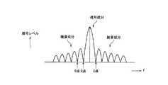
図5は、典型的な位相変調信号の周波数スペクトルを示す図である。 FIG. 5 is a diagram showing a frequency spectrum of a typical phase modulation signal.
図5において、中心の矢印で示しているのが、実際の信号成分である。位相変調信号は、実際の信号がある周波数だけでなく、前後に雑音成分が発生する。 In FIG. 5, the actual signal component is indicated by the center arrow. In the phase modulation signal, not only the frequency at which the actual signal is present but also noise components are generated before and after.
ただし、図5に示すように、位相変調信号の雑音成分には、一定周波数ごとに、信号レベルが0となる点(以下、「0点」)が存在する。この0点は、位相変調のシンボル周期に比例している。したがって、同じシンボル周期である信号では、同じ周期で0点が現れる。OFDM方式は、その0点となるところに、信号を重ね合わせて多重伝送を行う方式である。 However, as shown in FIG. 5, the noise component of the phase modulation signal has a point at which the signal level becomes 0 (hereinafter, “0 point”) at every constant frequency. This zero point is proportional to the symbol period of the phase modulation. Therefore, in a signal having the same symbol period, 0 points appear in the same period. The OFDM system is a system that performs multiplex transmission by superimposing signals at the zero point.
図6は、OFDM方式の周波数スペクトルを示す図である。 FIG. 6 is a diagram showing a frequency spectrum of the OFDM system.
図6に示すように、0点に他の信号を重ねれば(直交させれば)、お互いの信号が干渉することなく伝送を行うことができる。OFDMの信号帯域外に漏れる信号雑音についても、一定周波数ごとにレベルが0となる0点が存在する。 As shown in FIG. 6, if another signal is superimposed on the 0 point (orthogonalized), transmission can be performed without interference between the signals. For signal noise leaking outside the OFDM signal band, there are 0 points at which the level becomes 0 for each fixed frequency.
図7は、干渉発生時のOFDM隣接チャネルの周波数スペクトルを示す図である。 FIG. 7 is a diagram illustrating a frequency spectrum of an OFDM adjacent channel when interference occurs.
図7の例において、破線はドナー側送受信部100の受信信号(ドナー側信号RS1)、実線はサービス側送受信部200の送信信号(サービス側信号RS2)を示す。 In the example of FIG. 7, a broken line indicates a reception signal (donor side signal RS1) of the donor side transmission /
通常、OFDMの隣接セル間では直交性を有する周波数を用いないので、サービス側送受信部200の送信信号(サービス側信号RS2)の雑音がドナー側送受信部100の受信信号(ドナー側信号RS1)に干渉する。 Usually, since the frequency having orthogonality is not used between the adjacent cells of OFDM, the noise of the transmission signal (service side signal RS2) of the service side transmission /
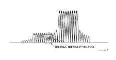
図8は、直交状態のOFDM隣接チャネルの周波数スペクトルを示す図である。 FIG. 8 is a diagram illustrating a frequency spectrum of an OFDM adjacent channel in an orthogonal state.
図8に示すように、第1実施形態に係る無線中継局10Aは、ドナー側送受信部100の受信信号(ドナー側信号RS1)と、サービス側送受信部200の送信信号(サービス側信号RS2)とを直交させることができる。 As illustrated in FIG. 8, the
すなわち、サービス側送受信部200の送信信号(サービス側信号RS2)の雑音の0点が、ドナー側送受信部100の受信信号(ドナー側信号RS1)の信号成分と重なるため、サービス側送受信部200の送信信号(サービス側信号RS2)の雑音が干渉しない。そのため、ドナー側送受信部100は、キャリア間干渉の影響を受けずに、正常に受信信号(ドナー側信号RS1)を復調することができる。 That is, the zero point of the noise of the transmission signal (service side signal RS2) of the service side transmission /
また、ドナー側送受信部100の送信信号(ドナー側信号RS1)の雑音の0点も、サービス側送受信部200の受信信号(サービス側信号RS2)の信号成分と重なることになるため、ドナー側送受信部100の送信信号(ドナー側信号RS1)の雑音が干渉しない。そのため、サービス側送受信部200は、キャリア間干渉の影響を受けずに、正常に受信信号(サービス側信号RS2)を復調することができる。 Further, since the zero point of the noise of the transmission signal (donor side signal RS1) of the donor side transmission /
(4)無線中継局の動作フロー
図9は、無線中継局10Aの動作例を示すフローチャートである。(4) Operation Flow of Radio Relay Station FIG. 9 is a flowchart showing an operation example of the
ステップS101において、ドナー側送受信部100は、無線基地局BSへの接続(ネットワークエントリ)を行う。ドナー側送受信部100は、サービス側送受信部200からサービス側信号RS2を受信する。 In step S101, the donor-
ステップS102において、ドナー側送受信部100の受信部122は、ドナー側アンテナANT1が受信したサービス側信号RS2をRF帯からBB帯にダウンコンバートし、且つ増幅する。ドナー側送受信部100のFFT処理部112は、受信部122からのサービス側信号RS2にFFTを施す。ドナー側送受信部100の信号レベル測定部113は、FFT後のサービス側信号RS2の信号レベルを測定する。測定された信号レベルは、制御部500によって記憶される。 In step S102, the receiving
ステップS103において、制御部500は、周波数シフト部223を用いて、サービス側周波数帯B2を初期値から所定量だけ上昇させる。 In step S103, the
ステップS104において、ドナー側送受信部100は、サービス側送受信部200からサービス側信号RS2を受信する。ステップS102と同様にして、ドナー側送受信部100の信号レベル測定部113は、FFT後のサービス側信号RS2の信号レベルを測定する。測定された信号レベルは、制御部500に通知される。 In step S104, the donor-side transmitting / receiving
ステップS105において、制御部500は、ステップS104で測定された信号レベルが、ステップS102で測定された信号レベルよりも低いか否かを判定する。ステップS104で測定された信号レベルが、ステップS102で測定された信号レベルよりも低い場合には、処理がステップS106に進む。一方、ステップS104で測定された信号レベルが、ステップS102で測定された信号レベル以上である場合には、処理がステップS109に進む。 In step S105, the
ステップS106において、制御部500は、周波数シフト部223を用いて、サービス側周波数帯B2をさらに所定量だけ上昇させる。 In step S106, the
ステップS107において、ドナー側送受信部100は、サービス側送受信部200からサービス側信号RS2を受信する。ステップS102と同様にして、ドナー側送受信部100の信号レベル測定部113は、FFT後のサービス側信号RS2の信号レベルを測定する。測定された信号レベルは、制御部500に通知される。 In step S107, the donor-side transmitting / receiving
ステップS108において、制御部500は、ステップS107で測定された信号レベルが、ステップS104で測定された信号レベルよりも低いか否かを判定する。ステップS107で測定された信号レベルが、ステップS104で測定された信号レベルよりも低い場合には、処理がステップS106に戻る。一方、ステップS107で測定された信号レベルが、ステップS104で測定された信号レベル以上である場合には、処理がステップS112に進む。 In step S108, the
ステップS109において、制御部500は、周波数シフト部223を用いて、サービス側周波数帯B2を初期値から所定量だけ低下させる。 In step S109, the
ステップS110において、ドナー側送受信部100は、サービス側送受信部200からサービス側信号RS2を受信する。ステップS102と同様にして、ドナー側送受信部100の信号レベル測定部113は、FFT後のサービス側信号RS2の信号レベルを測定する。測定された信号レベルは、制御部500に通知される。 In step S110, the donor-side transmitting / receiving
ステップS111において、制御部500は、ステップS110で測定された信号レベルが、ステップS102で測定された信号レベルよりも低いか否かを判定する。ステップS110で測定された信号レベルが、ステップS102で測定された信号レベルよりも低い場合には、処理がステップS109に戻る。その後のステップS109では、制御部500は、周波数シフト部223を用いて、サービス側周波数帯B2をさらに所定量だけ低下させることになる。一方、ステップS110で測定された信号レベルが、ステップS102で測定された信号レベル以上である場合には、処理がステップS112に進む。 In step S111, the
ステップS112において、制御部500は、複数回の信号レベル測定のうち最も低い信号レベルが測定された際のシフト量を、周波数シフト部223に設定する最終的なシフト量として決定する。 In step S <b> 112, the
なお、本動作フローでは、ステップS103において周波数を上昇させているが、これに代えて、ステップS103において周波数を低下させてもよい。この場合、ステップS106では、周波数の上昇に代えて周波数の低下を行うことになり、ステップS109では、周波数の低下に代えて周波数の上昇を行うことになる。 In this operation flow, the frequency is increased in step S103, but instead, the frequency may be decreased in step S103. In this case, in step S106, the frequency is decreased instead of increasing the frequency, and in step S109, the frequency is increased instead of decreasing the frequency.
以上説明したように、第1実施形態によれば、例えばドナー側信号RS1とサービス側信号RS2とをOFDM上で直交させることで、干渉を回避することができる。このため、TDD方式において隣接チャネルが存在する場合等に特に有効である。さらに、干渉低減用のフィルタ回路を必ずしも用いる必要がないため、他の周波数帯を用いるシステムへの転用が容易である。また、干渉低減用のフィルタ回路を必ずしも用いる必要がないため、小型化を図ることができる。 As described above, according to the first embodiment, interference can be avoided by, for example, orthogonalizing the donor-side signal RS1 and the service-side signal RS2 on OFDM. Therefore, this is particularly effective when there is an adjacent channel in the TDD system. Furthermore, since it is not always necessary to use a filter circuit for reducing interference, it can be easily transferred to a system using another frequency band. Further, since it is not always necessary to use a filter circuit for reducing interference, the size can be reduced.
第1実施形態では、ドナー側送受信部100は、無線端末MSがサービス側送受信部200に接続する前において、サービス側送受信部200からサービス側信号RS2を受信するため、周波数シフト部223におけるシフト量を決定することができ、無線端末MSとの無線通信に悪影響を与えることを防止できる。 In the first embodiment, the donor-side transmitting / receiving
なお、無線端末MSは、サービス側送受信部200に接続する際に、自動周波数制御により、シフト量が反映されたサービス側周波数帯B2に追従することができる。 When connecting to the service-
第1実施形態では、制御部500は、シフト量を変化させつつ信号レベルを信号レベル測定部113に複数回測定させ、複数回の測定のうち最も低い信号レベルが測定された際のシフト量を、周波数シフト部223に設定する最終的なシフト量として決定するため、効果的なシフト量を自動的に探索することができる。 In the first embodiment, the
[第2実施形態]
第2実施形態においては、第1実施形態と異なる点についてのみ説明する。図10は、第2実施形態に係る無線中継局10Bの構成を示すブロック図である。[Second Embodiment]
In the second embodiment, only differences from the first embodiment will be described. FIG. 10 is a block diagram showing a configuration of the
図10に示すように、無線中継局10Bは、アンテナANT、送受信部300及び制御部350を有する。送受信部300は、アンテナANTを介して、ドナー側周波数帯B1が用いられるドナー側信号RS1を無線基地局BSと送受信し、ドナー側周波数帯B1と隣接するサービス側周波数帯B2が用いられるサービス側信号RS2を無線端末MSと送受信する。制御部350は、送受信部300を制御する。 As illustrated in FIG. 10, the
第2実施形態において、送受信部300は、ドナー側信号RS1と直交するサービス側信号RS2を無線端末MSと送受信する。 In 2nd Embodiment, the transmission /
送受信部300は、信号処理部310及び無線部320を有する。信号処理部310は、BB帯のドナー側信号RS1及びサービス側信号RS2の両信号を処理する。無線部320は、RF帯のドナー側信号RS1及びサービス側信号RS2の両信号を処理する。 The transmission /
信号処理部310は、IFFT処理部311及びFFT処理部312を有する。IFFT処理部311は、IFFTにより、互いに直交する複数の第1サブキャリアをドナー側信号RS1に変換するとともに、互いに直交する複数の第2サブキャリアをサービス側信号RS2に変換する。 The
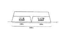
ここで、IFFT処理部311は、第1サブキャリア及び第2サブキャリアそれぞれを予め直交させている。すなわち、IFFT処理部311は、ドナー側周波数帯B1とサービス側周波数帯B2とを併せた周波数帯(すなわち、通常の倍の周波数帯)に対し、一括してIFFTを行うように構成されている(図11参照)。 Here, IFFT processing section 311 orthogonalizes each of the first subcarrier and the second subcarrier in advance. That is, the IFFT processing unit 311 is configured to collectively perform IFFT on a frequency band (that is, a normal double frequency band) including the donor-side frequency band B1 and the service-side frequency band B2. (See FIG. 11).
FFT処理部312は、FFTにより、ドナー側信号RS1を互いに直交する複数の第1サブキャリアに変換するとともに、サービス側信号RS2を互いに直交する複数の第2サブキャリアに変換する。FFT処理部312は、ドナー側周波数帯B1とサービス側周波数帯B2とを併せた周波数帯(すなわち、通常の倍の周波数帯)に対し、一括してFFTを行うように構成されている(図11参照)。 The
無線部320は、送信部321及び受信部322を有する。送信部321は、IFFT処理部311からのドナー側信号RS1及びサービス側信号RS2を一括してRF帯にアップコンバートし、且つ増幅し、アンテナANTから送出する。受信部322は、アンテナANTが受信したドナー側信号RS1及びサービス側信号RS2を一括してRF帯からBB帯にダウンコンバートし、且つ増幅する。 The
このように構成された無線中継局10Bの動作について、図11を参照しながら説明する。図11では、無線中継局10Aにおける全帯域が20MHzであると仮定している。 The operation of the
無線中継局10Bが無線基地局BSとの接続を行い、周波数が同期すると、ドナー側周波数帯B1(10MHz)が確定する。 When the
ドナー側周波数帯B1が同期すると、サービス側周波数帯B2も同期する。このため、無線中継局10A内部で、ドナー側信号RS1(第1サブキャリア)及びサービス側信号RS2(第2サブキャリア)を直交させることができる。 When the donor side frequency band B1 is synchronized, the service side frequency band B2 is also synchronized. For this reason, the donor-side signal RS1 (first subcarrier) and the service-side signal RS2 (second subcarrier) can be orthogonalized within the
このように、無線中継局10Bによれば、第1実施形態のようなシフト量調整処理を省略して、最初から、互いに直交するドナー側信号RS1及びサービス側信号RS2を送受信できる。したがって、第1実施形態において得られる効果に加え、無線中継局10Bの処理負荷を低減するという効果が得られる。 Thus, according to the
[その他の実施形態]
上記のように、本発明は実施形態によって記載したが、この開示の一部をなす論述及び図面はこの発明を限定するものであると理解すべきではない。この開示から当業者には様々な代替実施形態、実施例及び運用技術が明らかとなる。[Other Embodiments]
As mentioned above, although this invention was described by embodiment, it should not be understood that the description and drawing which form a part of this indication limit this invention. From this disclosure, various alternative embodiments, examples and operational techniques will be apparent to those skilled in the art.
上述した第1実施形態では、周波数シフト部223におけるシフト量を調整する構成について説明した。しかしながら、最適なシフト量が一旦確定すれば、無線中継局10Aは、以後のシフト量調整処理を省略し、シフト量を固定にしてもよい。 In the first embodiment described above, the configuration for adjusting the shift amount in the
上述した第1実施形態及び第2実施形態では、周波数領域の信号(サブキャリア)から時間領域の信号(ドナー側信号RS1又はサービス側信号RS2)への変換にIFFTを使用し、時間領域の信号(ドナー側信号RS1又はサービス側信号RS2)から周波数領域の信号(サブキャリア)への変換にFFTを使用していた。しかしながら、FFTに限らず、DFT(discrete Fourier transform)等を使用してもよい。 In the first and second embodiments described above, the IFFT is used for conversion from the frequency domain signal (subcarrier) to the time domain signal (donor side signal RS1 or service side signal RS2), and the time domain signal is used. An FFT is used for conversion from a (donor side signal RS1 or service side signal RS2) to a frequency domain signal (subcarrier). However, not limited to FFT, DFT (discrete Fourier transform) or the like may be used.
上述した実施形態では、WiMAX(IEEE802.16)に基づく無線通信システム1について説明したが、WiMAXに限らず、OFDM方式を採用する無線通信システムであればよく、例えば、次世代PHS(Personal Handyphone System)や、LTE(Long Term Evolution)などに対しても本発明を適用可能である。 In the above-described embodiment, the
上述した実施形態では、無線中継局10A及び無線中継局10Bとして固定型のものを説明したが、固定型に限らず、例えば車両などに搭載される移動型中継局であってもよい。 In the above-described embodiment, the fixed type is described as the
このように本発明は、ここでは記載していない様々な実施形態等を包含するということを理解すべきである。したがって、本発明はこの開示から妥当な特許請求の範囲の発明特定事項によってのみ限定されるものである。 Thus, it should be understood that the present invention includes various embodiments and the like not described herein. Therefore, the present invention is limited only by the invention specifying matters in the scope of claims reasonable from this disclosure.
ANT,ANT1,ANT2…アンテナ、BS…無線基地局、MS…無線端末、1…無線通信システム、10A,10B…無線中継局、100…ドナー側送受信部、110…信号処理部、111…IFFT処理部、112…FFT処理部、113…信号レベル測定部、120…無線部、121…送信部、122…受信部、150…制御部、200…サービス側送受信部、210…信号処理部、211…IFFT処理部、212…FFT処理部、220…無線部、221…送信部、222…受信部、223…周波数シフト部、250…制御部、300…送受信部、310…信号処理部、311…IFFT処理部、312…FFT処理部、320…無線部、321…送信部、322…受信部、350,500…制御部
ANT, ANT1, ANT2 ... antenna, BS ... wireless base station, MS ... wireless terminal, 1 ... wireless communication system, 10A, 10B ... wireless relay station, 100 ... donor side transmitting / receiving unit, 110 ... signal processing unit, 111 ... IFFT processing 112: FFT processing unit, 113 ... Signal level measurement unit, 120 ... Radio unit, 121 ... Transmission unit, 122 ... Reception unit, 150 ... Control unit, 200 ... Service side transmission / reception unit, 210 ... Signal processing unit, 211 ... IFFT processing unit, 212 ... FFT processing unit, 220 ... radio unit, 221 ... transmission unit, 222 ... reception unit, 223 ... frequency shift unit, 250 ... control unit, 300 ... transmission / reception unit, 310 ... signal processing unit, 311 ... IFFT Processing unit, 312 ... FFT processing unit, 320 ... Radio unit, 321 ... Transmission unit, 322 ... Reception unit, 350, 500 ... Control unit
Claims (6)
Translated fromJapanese第1周波数帯が用いられる第1信号を前記無線基地局と送受信する第1送受信部と、
第2周波数帯が用いられる第2信号を前記無線端末と送受信する第2送受信部と、
前記第1送受信部及び前記第2送受信部を制御する制御部と
を備え、
前記第2送受信部は、前記第2周波数帯をシフトする周波数シフト部を有し、
前記第1送受信部は、前記第2送受信部から前記第2信号を受信した際に、前記第1周波数帯における前記第2信号の信号レベルを測定し、
前記制御部は、前記第1送受信部によって測定された前記信号レベルが低下するように、前記周波数シフト部における前記第2周波数帯のシフト量を調整する無線中継局。A wireless relay station that relays communication between a wireless base station and a wireless terminal,
A first transmission / reception unit for transmitting / receiving a first signal using a first frequency band to / from the radio base station;
A second transmission / reception unit for transmitting / receiving a second signal using a second frequency band to / from the wireless terminal;
A control unit for controlling the first transmission / reception unit and the second transmission / reception unit;
The second transmission / reception unit includes a frequency shift unit that shifts the second frequency band,
The first transmitting / receiving unit measures the signal level of the second signal in the first frequency band when receiving the second signal from the second transmitting / receiving unit,
The control unit is a radio relay station that adjusts a shift amount of the second frequency band in the frequency shift unit so that the signal level measured by the first transmission / reception unit decreases.
前記シフト量を変化させつつ前記信号レベルを前記第1送受信部に複数回測定させ、
複数回の測定のうち最も低い前記信号レベルが測定された際の前記シフト量を、前記周波数シフト部に設定する前記シフト量として決定する請求項1又は2に記載の無線中継局。The controller is
The signal level is measured multiple times by the first transmitter / receiver while changing the shift amount,
The radio relay station according to claim 1 or 2, wherein the shift amount when the lowest signal level is measured among a plurality of measurements is determined as the shift amount set in the frequency shift unit.
前記第2信号は、互いに直交する複数の第2サブキャリアを用いて構成され、
前記制御部は、前記第2サブキャリアが前記第1サブキャリアに直交するように、前記シフト量を調整する請求項1〜3の何れか一項に記載の無線中継局。The first signal is configured using a plurality of first subcarriers orthogonal to each other,
The second signal is configured using a plurality of second subcarriers orthogonal to each other,
The radio relay station according to any one of claims 1 to 3, wherein the control unit adjusts the shift amount so that the second subcarrier is orthogonal to the first subcarrier.
フーリエ変換により、前記第1信号を前記第1サブキャリアに変換するフーリエ変換部と、
前記第2信号の前記信号レベルを測定する信号レベル測定部と
を備え、
前記信号レベル測定部は、前記フーリエ変換部による前記フーリエ変換後の前記第2信号の前記信号レベルを測定する請求項4に記載の無線中継局。The first transmission / reception unit includes:
A Fourier transform unit for transforming the first signal into the first subcarrier by Fourier transform;
A signal level measuring unit for measuring the signal level of the second signal,
The radio relay station according to claim 4, wherein the signal level measurement unit measures the signal level of the second signal after the Fourier transform by the Fourier transform unit.
第1周波数帯が用いられる第1信号を第1送受信部が無線基地局と送受信するステップと、
第2周波数帯が用いられる第2信号を第2送受信部が前記無線端末と送受信するステップと、
前記第1送受信部が、前記第2送受信部から前記第2信号を受信した際に、前記第1周波数帯における前記第2信号の信号レベルを測定するステップと、
前記第2送受信部に設けられた周波数シフト部が、前記第2周波数帯をシフトするステップと、
前記測定するステップにおいて測定された前記信号レベルが低下するように、前記周波数シフト部における前記第2周波数帯のシフト量を調整するステップと
を備える無線中継方法。A wireless relay method for relaying communication between a wireless base station and a wireless terminal,
A first transmitting / receiving unit transmitting and receiving a first signal using a first frequency band to and from a radio base station;
A second transmitting / receiving unit transmitting and receiving a second signal using the second frequency band to and from the wireless terminal;
Measuring the signal level of the second signal in the first frequency band when the first transmitter / receiver receives the second signal from the second transmitter / receiver;
A frequency shift unit provided in the second transmission / reception unit shifts the second frequency band;
Adjusting the shift amount of the second frequency band in the frequency shift unit so that the signal level measured in the measuring step decreases.
Priority Applications (5)
| Application Number | Priority Date | Filing Date | Title |
|---|---|---|---|
| JP2009077749AJP5342294B2 (en) | 2009-03-26 | 2009-03-26 | Radio relay station and radio relay method |
| KR1020117022768AKR101325404B1 (en) | 2009-03-26 | 2010-03-26 | Wireless relay station and wireless relay method |
| US13/259,506US8855041B2 (en) | 2009-03-26 | 2010-03-26 | Radio relay station and radio relay method |
| CN201080013450.4ACN102362446B (en) | 2009-03-26 | 2010-03-26 | Wireless relay station and wireless relay method |
| PCT/JP2010/055453WO2010110453A1 (en) | 2009-03-26 | 2010-03-26 | Wireless relay station and wireless relay method |
Applications Claiming Priority (1)
| Application Number | Priority Date | Filing Date | Title |
|---|---|---|---|
| JP2009077749AJP5342294B2 (en) | 2009-03-26 | 2009-03-26 | Radio relay station and radio relay method |
Publications (2)
| Publication Number | Publication Date |
|---|---|
| JP2010232921A JP2010232921A (en) | 2010-10-14 |
| JP5342294B2true JP5342294B2 (en) | 2013-11-13 |
Family
ID=42781143
Family Applications (1)
| Application Number | Title | Priority Date | Filing Date |
|---|---|---|---|
| JP2009077749AExpired - Fee RelatedJP5342294B2 (en) | 2009-03-26 | 2009-03-26 | Radio relay station and radio relay method |
Country Status (5)
| Country | Link |
|---|---|
| US (1) | US8855041B2 (en) |
| JP (1) | JP5342294B2 (en) |
| KR (1) | KR101325404B1 (en) |
| CN (1) | CN102362446B (en) |
| WO (1) | WO2010110453A1 (en) |
Families Citing this family (9)
| Publication number | Priority date | Publication date | Assignee | Title |
|---|---|---|---|---|
| CN103957597B (en)* | 2014-03-18 | 2017-09-22 | 南京邮电大学 | The relay selection and power joint optimization method matched based on selective subcarrier |
| JP6154857B2 (en)* | 2015-06-30 | 2017-06-28 | ソフトバンク株式会社 | Wireless communication relay device and wireless communication relay method |
| US20180234163A1 (en)* | 2015-08-13 | 2018-08-16 | Ntt Docomo, Inc. | Relay device and relay method |
| KR101954227B1 (en) | 2017-04-28 | 2019-05-17 | 주식회사 케이티 | Wireless relay apparatus and method of operating thereof |
| US11503647B2 (en)* | 2019-04-29 | 2022-11-15 | Qualcomm Incorporated | Beam management for direct and indirect links |
| WO2021163877A1 (en)* | 2020-02-18 | 2021-08-26 | Mediatek Singapore Pte. Ltd. | Methods and system of frequency synchronization mechanisms for integration terrestrial network and non terrestrial network |
| US20230113562A1 (en)* | 2021-10-08 | 2023-04-13 | Mediatek Inc. | Reliability enhancement in distributed system |
| KR102844922B1 (en)* | 2023-01-30 | 2025-08-13 | 주식회사 지노시스 | Different type of communication network repeater for IoT sensor operation |
| WO2024162568A1 (en)* | 2023-01-30 | 2024-08-08 | 주식회사 지노시스 | Heterogeneous communication network repeater for iot sensor operation |
Family Cites Families (31)
| Publication number | Priority date | Publication date | Assignee | Title |
|---|---|---|---|---|
| JP3112659B2 (en)* | 1997-05-30 | 2000-11-27 | 株式会社次世代デジタルテレビジョン放送システム研究所 | Frequency diversity system and its transmitting device and receiving device |
| JPH1141122A (en) | 1997-07-15 | 1999-02-12 | Nippon Telegr & Teleph Corp <Ntt> | Communication device |
| SE521005C2 (en)* | 1998-01-30 | 2003-09-23 | Ericsson Telefon Ab L M | A method and system for using diversity information extracted in the uplink during downlink transmission |
| KR100252490B1 (en)* | 1998-04-30 | 2000-04-15 | 이상철 | Radio communications system using satellite compensating for relay delay of satellite |
| JP2001016157A (en)* | 1999-07-01 | 2001-01-19 | Sumitomo Electric Ind Ltd | Roadside transmission system and roadside reception system |
| KR20020070729A (en)* | 2001-03-03 | 2002-09-11 | 주식회사 한화 | Signal repeater for radio communication system |
| JP2004349872A (en)* | 2003-05-20 | 2004-12-09 | Matsushita Electric Works Ltd | Radio relay apparatus |
| CN100531167C (en)* | 2003-05-28 | 2009-08-19 | 艾利森电话股份有限公司 | Method and system for wireless communication networks using relaying |
| JP4039373B2 (en)* | 2004-02-16 | 2008-01-30 | ソニー株式会社 | Wireless transmission / reception system |
| JP4652846B2 (en)* | 2004-03-11 | 2011-03-16 | パナソニック株式会社 | Communication terminal device and communication relay method |
| KR20050103633A (en)* | 2004-04-27 | 2005-11-01 | 주식회사 엠티아이 | Tx/rx switching method in ofdm/tdd system and repeater using the same |
| JP4494134B2 (en)* | 2004-09-01 | 2010-06-30 | Kddi株式会社 | Wireless communication system, relay station apparatus and base station apparatus |
| US7725074B2 (en) | 2005-02-18 | 2010-05-25 | Panasonic Corporation | Wireless communication method, relay station apparatus, and wireless transmitting apparatus |
| WO2007007179A2 (en)* | 2005-07-14 | 2007-01-18 | Nokia Corporation | Method, apparatus and computer program product providing randomized relay network |
| CN101047421B (en)* | 2006-04-28 | 2011-12-07 | 华为技术有限公司 | Device and method for mobile communication using repeater station |
| WO2007133022A1 (en)* | 2006-05-11 | 2007-11-22 | Samsung Electronics Co., Ltd. | Apparatus and method for providing relay link zone information in a multi-hop relay broadband wireless access communication system |
| JP4952135B2 (en)* | 2006-08-17 | 2012-06-13 | 富士通株式会社 | Wireless terminal, relay station, wireless base station, and communication method |
| JP4740069B2 (en)* | 2006-08-28 | 2011-08-03 | 日本放送協会 | Wraparound canceller |
| GB2441574A (en) | 2006-09-08 | 2008-03-12 | Fujitsu Ltd | Network entry to a multi-hop wireless communication system |
| JP4875504B2 (en)* | 2007-01-22 | 2012-02-15 | 株式会社日立国際電気 | OFDMA radio system and relay station |
| JP2008205564A (en)* | 2007-02-16 | 2008-09-04 | Oki Electric Ind Co Ltd | Radio relay method, radio equipment and radio relay system |
| KR100975726B1 (en)* | 2007-03-02 | 2010-08-12 | 삼성전자주식회사 | System and method for transmitting / receiving signal in communication system using relay method |
| RU2420886C1 (en)* | 2007-03-02 | 2011-06-10 | Квэлкомм Инкорпорейтед | Repeater configuration |
| JP4569591B2 (en)* | 2007-03-20 | 2010-10-27 | 財団法人北九州産業学術推進機構 | Adaptive canceling method of sneak wave in OFDM-based SFN repeater |
| KR100985395B1 (en)* | 2007-04-03 | 2010-10-05 | 연세대학교 산학협력단 | Transmission apparatus and method in orthogonal frequency division multiplexing communication system |
| WO2009011135A1 (en)* | 2007-07-19 | 2009-01-22 | Panasonic Corporation | Relay station, mobile station, and relay transmission method in mobile communication system |
| KR101400240B1 (en)* | 2007-10-18 | 2014-06-30 | 포항공과대학교 산학협력단 | System for generating space frequency block code relay signal and method thereof |
| KR101434566B1 (en)* | 2008-01-02 | 2014-08-27 | 삼성전자주식회사 | Repeater-based communication system for processing signals without a cyclic prefix and method therefor |
| US8605654B2 (en)* | 2008-04-21 | 2013-12-10 | Apple, Inc. | Apparatus, system, and method for a remote radio module with relay capability |
| WO2010113261A1 (en)* | 2009-03-31 | 2010-10-07 | 富士通株式会社 | Relay station, base station, mobile station, and relay method in wireless communication network |
| WO2013013288A1 (en)* | 2011-07-26 | 2013-01-31 | Research In Motion Limited | Mobile device for a smart relay network |
- 2009
- 2009-03-26JPJP2009077749Apatent/JP5342294B2/ennot_activeExpired - Fee Related
- 2010
- 2010-03-26CNCN201080013450.4Apatent/CN102362446B/ennot_activeExpired - Fee Related
- 2010-03-26WOPCT/JP2010/055453patent/WO2010110453A1/enactiveApplication Filing
- 2010-03-26KRKR1020117022768Apatent/KR101325404B1/ennot_activeExpired - Fee Related
- 2010-03-26USUS13/259,506patent/US8855041B2/ennot_activeExpired - Fee Related
Also Published As
| Publication number | Publication date |
|---|---|
| US8855041B2 (en) | 2014-10-07 |
| KR20110122756A (en) | 2011-11-10 |
| CN102362446A (en) | 2012-02-22 |
| JP2010232921A (en) | 2010-10-14 |
| US20120020239A1 (en) | 2012-01-26 |
| CN102362446B (en) | 2014-09-17 |
| KR101325404B1 (en) | 2013-11-04 |
| WO2010110453A1 (en) | 2010-09-30 |
Similar Documents
| Publication | Publication Date | Title |
|---|---|---|
| JP5342294B2 (en) | Radio relay station and radio relay method | |
| US8725067B2 (en) | Self-interference cancellation method and apparatus of relay using the same frequency band in OFDM-based radio communication system | |
| US7907572B2 (en) | Collocated radio coexistence method | |
| EP2175684B1 (en) | Uplink (UL) power control apparatus and method in broadband wireless communication system | |
| US20180167954A1 (en) | Method and apparatus for reporting channel state information in wireless communication system | |
| US8477860B2 (en) | OFDM signal reception in the presence of interference | |
| US8737529B2 (en) | Multiple antenna signal transmission | |
| KR100922949B1 (en) | Method for receiving signal in a communication system and system thereof | |
| KR101459014B1 (en) | Apparatus and method for frequency control in mobile communication system | |
| US20090264087A1 (en) | Apparatus and method for beamforming considering interference amount in broadband wireless communication system | |
| US8560000B2 (en) | Transmit power control method for reducing cellular interference in cellular radio communication system and radio base station device for implementing the same | |
| US8948035B2 (en) | Wireless communication systems employing communication schemes | |
| KR20090088086A (en) | Power Control Device and Method in Distributed Antenna System | |
| US20130100826A1 (en) | Radio relay apparatus and control method | |
| KR100975726B1 (en) | System and method for transmitting / receiving signal in communication system using relay method | |
| US20080280580A1 (en) | Image compensation for wireless receiver | |
| EP2745406B1 (en) | Method for controlling performance in a radio base station arranged for communication in tdd mode, and radio base station | |
| WO2011118730A1 (en) | Wireless base station and communications control method | |
| WO2011118729A1 (en) | Wireless base station and communications control method | |
| US11528732B2 (en) | Method and network node for handling transmission of LTE or NR signals and NB-IoT signals to wireless communication devices | |
| JP2003174428A (en) | OFDM transceiver | |
| Yasaka et al. | BER Comparison Between Time-Domain and Frequency-Domain Self-Interference Canceller in 5G-Based Full-Duplex Mobile Communications | |
| WO2016070307A1 (en) | Processing method and apparatus for eliminating interference of adjacent bands in wireless system | |
| WO2017168712A1 (en) | Base station apparatus, terminal apparatus, wireless communication system, and wireless communication method | |
| JP2011176499A (en) | Wireless communication system, base station, repeater, and wireless communication method |
Legal Events
| Date | Code | Title | Description |
|---|---|---|---|
| A621 | Written request for application examination | Free format text:JAPANESE INTERMEDIATE CODE: A621 Effective date:20120203 | |
| A131 | Notification of reasons for refusal | Free format text:JAPANESE INTERMEDIATE CODE: A131 Effective date:20130430 | |
| A521 | Request for written amendment filed | Free format text:JAPANESE INTERMEDIATE CODE: A523 Effective date:20130701 | |
| TRDD | Decision of grant or rejection written | ||
| A01 | Written decision to grant a patent or to grant a registration (utility model) | Free format text:JAPANESE INTERMEDIATE CODE: A01 Effective date:20130723 | |
| A61 | First payment of annual fees (during grant procedure) | Free format text:JAPANESE INTERMEDIATE CODE: A61 Effective date:20130809 | |
| R150 | Certificate of patent or registration of utility model | Ref document number:5342294 Country of ref document:JP Free format text:JAPANESE INTERMEDIATE CODE: R150 Free format text:JAPANESE INTERMEDIATE CODE: R150 | |
| LAPS | Cancellation because of no payment of annual fees |