JP5340845B2 - Emergency rolling bearing not affected by axial load - Google Patents
Emergency rolling bearing not affected by axial loadDownload PDFInfo
- Publication number
- JP5340845B2 JP5340845B2JP2009173785AJP2009173785AJP5340845B2JP 5340845 B2JP5340845 B2JP 5340845B2JP 2009173785 AJP2009173785 AJP 2009173785AJP 2009173785 AJP2009173785 AJP 2009173785AJP 5340845 B2JP5340845 B2JP 5340845B2
- Authority
- JP
- Japan
- Prior art keywords
- bearing
- emergency
- members
- intermediate support
- rotor
- Prior art date
- Legal status (The legal status is an assumption and is not a legal conclusion. Google has not performed a legal analysis and makes no representation as to the accuracy of the status listed.)
- Expired - Fee Related
Links
- 238000005096rolling processMethods0.000titleclaimsdescription16
- 230000002093peripheral effectEffects0.000claimsdescription4
- 239000002184metalSubstances0.000claimsdescription3
- 238000000926separation methodMethods0.000claims1
- 238000010276constructionMethods0.000description1
- 230000006378damageEffects0.000description1
- 230000009977dual effectEffects0.000description1
- 230000000694effectsEffects0.000description1
- 239000000725suspensionSubstances0.000description1
- 230000008961swellingEffects0.000description1
Images

Classifications
- F—MECHANICAL ENGINEERING; LIGHTING; HEATING; WEAPONS; BLASTING
- F16—ENGINEERING ELEMENTS AND UNITS; GENERAL MEASURES FOR PRODUCING AND MAINTAINING EFFECTIVE FUNCTIONING OF MACHINES OR INSTALLATIONS; THERMAL INSULATION IN GENERAL
- F16C—SHAFTS; FLEXIBLE SHAFTS; ELEMENTS OR CRANKSHAFT MECHANISMS; ROTARY BODIES OTHER THAN GEARING ELEMENTS; BEARINGS
- F16C27/00—Elastic or yielding bearings or bearing supports, for exclusively rotary movement
- F16C27/04—Ball or roller bearings, e.g. with resilient rolling bodies
- F—MECHANICAL ENGINEERING; LIGHTING; HEATING; WEAPONS; BLASTING
- F16—ENGINEERING ELEMENTS AND UNITS; GENERAL MEASURES FOR PRODUCING AND MAINTAINING EFFECTIVE FUNCTIONING OF MACHINES OR INSTALLATIONS; THERMAL INSULATION IN GENERAL
- F16C—SHAFTS; FLEXIBLE SHAFTS; ELEMENTS OR CRANKSHAFT MECHANISMS; ROTARY BODIES OTHER THAN GEARING ELEMENTS; BEARINGS
- F16C32/00—Bearings not otherwise provided for
- F16C32/04—Bearings not otherwise provided for using magnetic or electric supporting means
- F16C32/0406—Magnetic bearings
- F16C32/044—Active magnetic bearings
- F16C32/0442—Active magnetic bearings with devices affected by abnormal, undesired or non-standard conditions such as shock-load, power outage, start-up or touchdown
- F—MECHANICAL ENGINEERING; LIGHTING; HEATING; WEAPONS; BLASTING
- F16—ENGINEERING ELEMENTS AND UNITS; GENERAL MEASURES FOR PRODUCING AND MAINTAINING EFFECTIVE FUNCTIONING OF MACHINES OR INSTALLATIONS; THERMAL INSULATION IN GENERAL
- F16C—SHAFTS; FLEXIBLE SHAFTS; ELEMENTS OR CRANKSHAFT MECHANISMS; ROTARY BODIES OTHER THAN GEARING ELEMENTS; BEARINGS
- F16C39/00—Relieving load on bearings
- F16C39/02—Relieving load on bearings using mechanical means
- F—MECHANICAL ENGINEERING; LIGHTING; HEATING; WEAPONS; BLASTING
- F16—ENGINEERING ELEMENTS AND UNITS; GENERAL MEASURES FOR PRODUCING AND MAINTAINING EFFECTIVE FUNCTIONING OF MACHINES OR INSTALLATIONS; THERMAL INSULATION IN GENERAL
- F16C—SHAFTS; FLEXIBLE SHAFTS; ELEMENTS OR CRANKSHAFT MECHANISMS; ROTARY BODIES OTHER THAN GEARING ELEMENTS; BEARINGS
- F16C19/00—Bearings with rolling contact, for exclusively rotary movement
- F16C19/54—Systems consisting of a plurality of bearings with rolling friction
- F16C19/541—Systems consisting of juxtaposed rolling bearings including at least one angular contact bearing
- F16C19/542—Systems consisting of juxtaposed rolling bearings including at least one angular contact bearing with two rolling bearings with angular contact
- F—MECHANICAL ENGINEERING; LIGHTING; HEATING; WEAPONS; BLASTING
- F16—ENGINEERING ELEMENTS AND UNITS; GENERAL MEASURES FOR PRODUCING AND MAINTAINING EFFECTIVE FUNCTIONING OF MACHINES OR INSTALLATIONS; THERMAL INSULATION IN GENERAL
- F16C—SHAFTS; FLEXIBLE SHAFTS; ELEMENTS OR CRANKSHAFT MECHANISMS; ROTARY BODIES OTHER THAN GEARING ELEMENTS; BEARINGS
- F16C2300/00—Application independent of particular apparatuses
- F16C2300/02—General use or purpose, i.e. no use, purpose, special adaptation or modification indicated or a wide variety of uses mentioned
Landscapes
- Engineering & Computer Science (AREA)
- General Engineering & Computer Science (AREA)
- Mechanical Engineering (AREA)
- Magnetic Bearings And Hydrostatic Bearings (AREA)
- Support Of The Bearing (AREA)
- Vibration Prevention Devices (AREA)
- Rolling Contact Bearings (AREA)
Description
Translated fromJapanese 本発明は、ロータに関してわずかなエアギャップのある磁気軸受を有する回転機械のための、アキシアル荷重の影響を受けない非常用転がり軸受に関連する。前記非常用軸受は、少なくとも第1および第2の軸受部材を具備し、前記第1および第2の軸受部材の各々と前記ロータとの間に、前記複数の磁気軸受の前記わずかなラジアルエアギャップεrのほぼ半分であるεr/2値のラジアル隙間が設けられており、アキシアル隙間εaは、前記アセンブリと、前記ロータに固定されている第1および第2のアキシアル隣接部材との間で、前記第1および第2の軸受部材の両側に形成されている。The present invention relates to an emergency rolling bearing that is unaffected by axial loads for a rotating machine having a magnetic bearing with a slight air gap with respect to the rotor. The emergency bearing includes at least first and second bearing members, and the small radial air gaps of the plurality of magnetic bearings between each of the first and second bearing members and the rotor. epsilon is the radial clearance of the
非常用軸受として知られている、非常用機械的装置は、すでに特許文献FR 2 613 791およびEP 1 395 758 B1で特に説明されており、磁気軸受がオーバーロードされた場合、または電気制御装置または電子制御装置が機能しない場合、または磁気のサスペンションが止められた場合に、アクティブ磁気軸受を持つ回転機械の完全な無欠の状態(total integrity)を保証するように設計されている。 Emergency mechanical devices, known as emergency bearings, have already been described in particular in
文献EP 1 395 758 B1において、図2に示されているように、各々がステーターリング1と、複数のロータリング2と、ステーターおよび複数のロータリング1および2間に配置されている複数の転動体3と、を持つ2つの転がり軸受を有する非常用軸受が特に提案されている。複数のロータリング2は、ラジアル隙間4によってロータ6から分離されており、アキシアル隙間5によって第1および第2のアキシアル隣接部材7,8からも分離されている。 In the document EP 1 395 758 B1, as shown in FIG. 2, a stator ring 1, a plurality of
中間支持部材9は、ステーターリング1とステーター部材10との間に挿入されており、ステーター15に留められているステーター部材10に関連するラジアル隙間11,13を持つ。中間支持部材9の2つの一番端の側面に留められているばね12は、双方向のプレローディング(pre-loading)をかけることによって転がり部材上で軸方向に作動する。ラジアル方向に作動するダンパー手段は、隙間13に挿入され、非常に低い摩擦の接触手段14は、向かい合った、中間部材9の回転軸に対して垂直な表面とステーター部材10の表面との間に設けられている。 The intermediate support member 9 is inserted between the stator ring 1 and the
このような非常用装置は、アキシアル荷重の方向にかかわらずダンパーとして作動可能である。それにもかかわらず、その構成のタイプは、そのハウジングにおける軸受の熱膨張を避けることができず、この熱膨張は、ボールおよびリングがより高い応力を受ける原因となり、軸受が破壊される原因ともなる。 Such an emergency device can operate as a damper regardless of the direction of the axial load. Nevertheless, the type of construction cannot avoid the thermal expansion of the bearing in its housing, which causes the balls and rings to be subjected to higher stresses and also causes the bearing to break. .
この欠点を改善するために、隙間13に挿入されているダンパー手段とできる限り類似している第2の弾性装置13’を、複数のステーターリングを構成する軸受の複数の外輪1と、複数のステーターリングの支持部として作動する中間部材9との間の境界面に挿入することに、1つの可能な解決策はあるが、それによって、軸受は応力なしに膨張する。 In order to remedy this drawback, the second
この解決策は、従来技術を改善し、熱膨張の問題も解決されるが、それにもかかわらず、アセンブリのラジアル振れ(the radial deflection)が増大する欠点がある。 This solution improves upon the prior art and also solves the problem of thermal expansion, but nevertheless has the drawback of increasing the radial deflection of the assembly.
本発明は、摩耗を制限して高い水準の運転の安全性を持つ非常用軸受を提供することによって、上述した欠点を改善しようとするものである。 The present invention seeks to remedy the above-mentioned drawbacks by providing an emergency bearing that limits wear and has a high level of operational safety.
より具体的には、本発明は、軸受の温度上昇と、熱的に膨張している軸受に関連した結果と、を軽減すると同時に、アセンブリのラジアル振れを制限することを可能にしようとするものである。 More specifically, the present invention seeks to be able to limit the radial run-out of the assembly while reducing the bearing temperature rise and the consequences associated with thermally expanding bearings. It is.
これらの目的は、ロータに関してわずかなエアギャップのある複数の磁気軸受を有する回転機械のための、アキシアル荷重の影響を受けない非常用転がり軸受であって、前記非常用軸受は、少なくとも第1および第2の軸受部材を具備し、前記第1および第2の軸受部材の各々と前記ロータとの間に、前記複数の磁気軸受の前記わずかなラジアルエアギャップεrのほぼ半分であるεr/2値のラジアル隙間が設けられており、アキシアル隙間εaは、前記アセンブリと、前記ロータに固定されている第1および第2のアキシアル隣接部材との間で、前記第1および第2の軸受部材の両側に形成されており、前記非常用軸受は、前記第1の軸受部材は、ステーター部材と同軸の第1の中間支持部材に直接取り付けられていることと、前記第2の軸受部材は、同様に前記ステーター部材と同軸の第2の中間支持部材に取り付けられていることと、前記第1および第2の中間支持部材は、前記軸受の軸に対して垂直のラジアル平面において接触面を持ち、軸方向に作動し、前記第1および第2の中間支持部材と、前記第1および第2の軸受部材と、が膨張するまたは軸方向に離れるのを可能にする弾性プレストレスト部材によって一体化されていることと、ラジアル方向にあるダンパー手段は、最初に、前記第1および第2の中間支持部材間に、次いで前記ステーター部材間に挿入されていることと、を特徴とする。These objectives are emergency rolling bearings that are unaffected by axial loads for a rotating machine having a plurality of magnetic bearings with a slight air gap with respect to the rotor, the emergency bearing comprising at least a first and a A second bearing member, between each of the first and second bearing members and the rotor, εr / which is approximately half of the slight radial air gap εr of the plurality of magnetic bearings. A binary radial gap is provided, and the axial gap εa is defined between the first bearing and the second bearing between the assembly and the first and second axially adjacent members fixed to the rotor. The first bearing member is directly attached to a first intermediate support member coaxial with the stator member, and the second bearing member is formed on both sides of the member. Similarly, the bearing member is attached to a second intermediate support member coaxial with the stator member, and the first and second intermediate support members are a radial plane perpendicular to the axis of the bearing. Elastic prestressed having a contact surface and actuating in an axial direction, allowing the first and second intermediate support members and the first and second bearing members to expand or disengage in the axial direction Characterized in that it is integrated by a member and that the radial damper means is first inserted between the first and second intermediate support members and then between the stator members. To do.
より具体的には、非常用軸受は、非常に低い摩擦係数を持つ2つの環状エンドプレートを含み、前記2つの環状エンドプレートは、前記ステーター部材に固着されており、それらの間には、隙間をもって前記中間支持部材が挿入されている。 More specifically, the emergency bearing includes two annular end plates having a very low coefficient of friction, and the two annular end plates are fixed to the stator member, and there is a gap between them. The intermediate support member is inserted.
第1の可能な実施形態において、ダンパー手段は、中間支持部材の円筒状表面と、軸受の軸の中心に置かれているステーター部材と、の間に挿入されている波形金属リボンを有する。 In a first possible embodiment, the damper means comprises a corrugated metal ribbon inserted between the cylindrical surface of the intermediate support member and a stator member located in the center of the shaft of the bearing.
もう一つの実施形態において、ダンパー手段は、中間支持部材の円筒状表面と、軸受の軸の中心に置かれているステーター部材と、の間に挿入されている粘弾性リングを有する。 In another embodiment, the damper means has a viscoelastic ring inserted between the cylindrical surface of the intermediate support member and a stator member located in the center of the shaft of the bearing.
本発明の第1の用途において、非常用軸受は、中央のロータと、上記中央のロータの周囲の外側に配置されている第1および第2の軸受部材と、を含む。 In the first application of the present invention, the emergency bearing includes a central rotor and first and second bearing members disposed outside the periphery of the central rotor.
もう一つの用途において、非常用軸受は、管状の周辺的なロータと、周辺的なロータに面している内側に配置されている第1および第2の軸受部材と、を含む。 In another application, the emergency bearing includes a tubular peripheral rotor and first and second bearing members disposed on the inside facing the peripheral rotor.
本発明の他の特質および利点は、例として挙げられている実施形態の以下の記述から、および添付図面を参照して説明される。 Other features and advantages of the present invention will be described from the following description of exemplary embodiments given by way of example and with reference to the accompanying drawings.
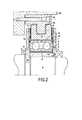
図1は、本発明に従った非常用転がり軸受の好適な実施形態を示している。 FIG. 1 shows a preferred embodiment of an emergency rolling bearing according to the invention.
図1に示されている非常用軸受は、アクティブ磁気軸受(図示されていない)と組み合わせて用いられるように設計されている。 The emergency bearing shown in FIG. 1 is designed to be used in combination with an active magnetic bearing (not shown).
図1において、様々な構成を持つ、すなわち、特にロータ106がステーター115の内部または外部のどちらにあるのも可能である、ロータ106およびステーター115が示されている。 In FIG. 1, the
非常用軸受は、2つの転がり軸受100A,100Bを本質的に有する。各軸受100A,100Bは、ステーターリング101A,101Bと、ロータリング102A,102Bと、ステーターおよびロータリング101A,102A間または101B,102B間に配置されている転動体103A,103Bと、を有する。 The emergency bearing essentially has two
非常用軸受が関連付けられているラジアル磁気軸受の通常運転において、軸受のロータリング102Aおよび102Bは、磁気軸受のエアギャップεr値の約半分であるεr/2値のラジアル隙間104によってロータ106から分離されている。In normal operation of a radial magnetic bearing with an associated emergency bearing, the
εr/2値のラジアル隙間は、0.15ミリメートル(mm)から0.3mmの範囲にあるのが好ましいが、用途によってこの範囲外も可能である。The radial clearance of εr / 2 is preferably in the range of 0.15 millimeters (mm) to 0.3 mm, but can be outside this range depending on the application.
ロータリング102Aおよび102Bはそれぞれ、好ましくは約0.2mmから0.5mmの範囲にあるが用途によって上記範囲外も可能であるアキシアル隙間105によって、第1のアキシアル隣接部材107および第2のアキシアル隣接部材108から一定の間隔をあけて離れている。これらのアキシアル隙間は、軸受がアキシアル荷重の場合にいずれの方向にも軸方向運動するのを可能にする。 Each of the
本発明によると、第1の軸受100Aは、第1の中間支持部材109A内に取り付けられている。ダンパー手段113は、上記中間支持部材109Aと、ねじのような留め金具部材119によってステーター115に留められている支持部材110と、の間に挿入されている。 According to the present invention, the first bearing 100A is mounted in the first
同様に、第2の軸受100Bは、第2の中間支持部材109B内に取り付けられている。ダンパー手段113もまた、上記第2の中間支持部材109Bと、ステーター支持部材110と、の間に挿入されている。 Similarly, the second bearing 100B is mounted in the second
第1および第2の中間支持部材109Aおよび109Bは、軸受およびロータ106の軸に対して垂直のラジアル平面において接触面を呈する。2つの中間支持部材109Aおよび109Bは、例えば、軸方向に作動し、中間部材109Aおよび109Bを第1および第2の軸受から軸方向に離すことによって、第1および第2の軸受が膨張(expand)するのを可能にするコイルばねの形をとる、弾性プレストレスト部材112によって一体化されている。 The first and second intermediate support members 109 </ b> A and 109 </ b> B present a contact surface in a radial plane perpendicular to the bearing and
中間支持部材109Aおよび109Bは、ボルトのような取り付け手段118によってステーター部材110に留められている環状エンドプレート116および117間にある隙間に挿入されている。これらのプレートは、非常に低い摩擦係数および最大表面積を持つように選択されている。 The
ステーターのそばに位置している中間支持部材109Aおよび109Bの円筒状表面と、中間支持部材109Aおよび109Bに面して位置しているステーター部材110の円筒状表面との間に挿入されているダンパー手段113は波形金属リボンまたは粘弾性リングによって構成されている。 Damper inserted between the cylindrical surface of
軸受100Aおよび100Bはそれぞれ、中間部材109Aおよび109B間の接触面から対向して、第1および第2の中間支持部材109Aおよび109B内にそれぞれの側面で受け入れられる。 The
非常用軸受システムに当てられるアキシアル荷重がどんなものであっても、前記アキシアル荷重から生じるラジアル摩擦は、プレート116および117の低い摩擦係数のため、システムのラジアル方向における自由運動を阻むことができない。 Whatever the axial load applied to the emergency bearing system, the radial friction resulting from the axial load cannot prevent free movement in the radial direction of the system due to the low coefficient of friction of the
軸受100Aおよび100Bは、中間支持部材109Aおよび109Bに直接取り付けられているので、2つの支持部材を、ばね112によって弾性フリー荷重の状態に置く。ステーターリング101A,101Bと、中間支持部材109A,109Bと、の間に優れた熱接触があるとすると、ステーターリング101Aおよび101Bの熱膨張は、非常に制限される。Since the
さらに、ロータリング102A,102Bおよび熱的に膨張しているボール103A,103Bの影響下で、それらは軸受の接触角に沿ってステーターリング101A,101Bに圧力をかける。この圧力下で、2つの中間支持部材109Aおよび109Bは、アセンブリのいずれのパーツにも過度に応力を加えることなく互いに離れることができる。 Furthermore, under the influence of the
上述したアセンブリは、どんな種類のダンパー手段も、ステーターリング101Aおよび101Bと、中間支持部材109A,109Bと、の間に挿入されないため、ラジアル振れを制限する利点と、軸受の温度上昇を制限する、したがって中間支持部材109Aおよび109Bは、応力なしに膨張できるまたは離れることができる少なくとも2つの部分であり、それによって、軸受のステーターリング101Aおよび101Bは、離れて、軸受に応力をかけることなく膨張も可能となるという結果として、膨張と関連した破壊のリスクを制限する利点の2重の利点を呈する。 The assembly described above does not insert any kind of damper means between the
1 …ステーターリング
2 …ロータリング
3 …転動体
4 …ラジアル隙間
5 …アキシアル隙間
6 …ロータ
9 …中間支持部材
10 …ステーター部材
11 …ラジアル隙間
12 …ばね
13 …隙間
13’ …弾性装置
14 …接触手段
15 …ステーター
100A…転がり軸受
100B…転がり軸受
101A…ステーターリング
101B…ステーターリング
102A…ロータリング
102B…ロータリング
103A…転動体
103B…転動体
104 …ラジアル隙間
105 …アキシアル隙間
106 …ロータ
107 …アキシアル隣接部材
108 …アキシアル隣接部材
109A…上記中間支持部材
109B…中間支持部材
110 …ステーター支持部材
112 …弾性プレストレスト部材
113 …ダンパー手段
115 …ステーター
116 …環状エンドプレート
117 …環状エンドプレート
118 …取り付け手段
119 …金具部材DESCRIPTION OF SYMBOLS 1 ...
Claims (7)
Translated fromJapanese前記非常用軸受は、少なくとも第1および第2の軸受部材(100A,100B)を具備し、前記第1および第2の軸受部材(100A,100B)の各々と前記ロータ(106)との間に、前記複数の磁気軸受の前記わずかなラジアルエアギャップεrのほぼ半分であるεr/2値のラジアル隙間(104)が設けられており、アキシアル隙間εa(105)は、前記アセンブリと、前記ロータ(106)に固定されている第1および第2のアキシアル隣接部材(107,108)との間で、前記第1および第2の軸受部材(100A,100B)の両側に形成されており、
前記非常用軸受は、
前記第1の軸受部材(100A)は、ステーター部材(110)と同軸の第1の中間支持部材(109A)に直接取り付けられていることと、
前記第2の軸受部材(100B)は、同様に前記ステーター部材(110)と同軸の第2の中間支持部材(109B)に取り付けられていることと、
前記第1および第2の中間支持部材(109A,109B)は、前記軸受の軸に対して垂直のラジアル平面において接触面を持ち、軸方向に作動し、前記第1および第2の中間支持部材(109A,109B)と、前記第1および第2の軸受部材(100A,100B)と、が膨張するまたは軸方向に離れるのを可能にする弾性プレストレスト部材(112)によって一体化されていることと、
ラジアル方向にあるダンパー手段(113)は、最初に、前記第1および第2の中間支持部材(109A,109B)間に、次いで前記ステーター部材(110)間に挿入されていることと、
を特徴とする非常用転がり軸受。An emergency rolling bearing, unaffected by axial loads, for a rotating machine having a plurality of magnetic bearings with a slight air gap with respect to the rotor (106),
The emergency bearing includes at least first and second bearing members (100A, 100B), and between each of the first and second bearing members (100A, 100B) and the rotor (106). , A radial clearance (104) of εr / 2 which is approximately half of the slight radial air gap εr of the plurality of magnetic bearings, and an axial clearance εa (105), It is formed on both sides of the first and second bearing members (100A, 100B) between the first and second axially adjacent members (107, 108) fixed to the rotor (106). ,
The emergency bearing is
The first bearing member (100A) is directly attached to a first intermediate support member (109A) coaxial with the stator member (110);
The second bearing member (100B) is similarly attached to a second intermediate support member (109B) coaxial with the stator member (110);
The first and second intermediate support members (109A, 109B) have a contact surface in a radial plane perpendicular to the shaft of the bearing and operate in the axial direction. The first and second intermediate support members (109A, 109B) and the first and second bearing members (100A, 100B) being integrated by an elastic prestressed member (112) that allows expansion or axial separation. ,
The damper means (113) in the radial direction is first inserted between the first and second intermediate support members (109A, 109B) and then between the stator members (110);
An emergency rolling bearing characterized by
Applications Claiming Priority (2)
| Application Number | Priority Date | Filing Date | Title |
|---|---|---|---|
| FR0855131 | 2008-07-25 | ||
| FR0855131AFR2934339B1 (en) | 2008-07-25 | 2008-07-25 | INSENSITIVE EMERGENCY BEARING WITH AXIAL LOAD |
Publications (2)
| Publication Number | Publication Date |
|---|---|
| JP2010091106A JP2010091106A (en) | 2010-04-22 |
| JP5340845B2true JP5340845B2 (en) | 2013-11-13 |
Family
ID=40364495
Family Applications (1)
| Application Number | Title | Priority Date | Filing Date |
|---|---|---|---|
| JP2009173785AExpired - Fee RelatedJP5340845B2 (en) | 2008-07-25 | 2009-07-27 | Emergency rolling bearing not affected by axial load |
Country Status (4)
| Country | Link |
|---|---|
| US (1) | US8106556B2 (en) |
| EP (1) | EP2148102B1 (en) |
| JP (1) | JP5340845B2 (en) |
| FR (1) | FR2934339B1 (en) |
Families Citing this family (4)
| Publication number | Priority date | Publication date | Assignee | Title |
|---|---|---|---|---|
| US8182153B2 (en)* | 2009-02-27 | 2012-05-22 | General Electric Company | Bearing damper with spring seal |
| US9685839B2 (en) | 2013-03-20 | 2017-06-20 | Fxq Engineering Group, Llc | Bearing implementation for a rotating electrical device |
| US10215230B2 (en)* | 2016-09-24 | 2019-02-26 | Radiant Physics Inc. | Pressurized gas bearings for rotating machinery |
| DE102016012246A1 (en)* | 2016-10-14 | 2018-04-19 | Thyssenkrupp Ag | Electromechanical power steering with sprung bearing arrangement |
Family Cites Families (10)
| Publication number | Priority date | Publication date | Assignee | Title |
|---|---|---|---|---|
| DE2242852A1 (en)* | 1972-08-31 | 1974-03-14 | Motoren Turbinen Union | DEVICE FOR THE SOFT AND ELASTIC MOUNTING OF HIGH SPEED ROTATING SHAFTS |
| DE2515414C3 (en)* | 1975-04-09 | 1980-01-03 | Messerschmitt-Boelkow-Blohm Gmbh, 8000 Muenchen | Rotor blade control device for helicopters |
| DE3141841A1 (en)* | 1981-10-22 | 1983-05-05 | Brown, Boveri & Cie Ag, 6800 Mannheim | "CENTERING AND CATCHING DEVICE FOR CONTACTLESSLY BEARED ROTORS" |
| JPS6058957U (en)* | 1983-09-28 | 1985-04-24 | 東洋電機製造株式会社 | gear system |
| FR2613791B1 (en) | 1987-04-09 | 1992-03-13 | Europ Propulsion | RADIAL MAGNETIC BEARING WITH EMERGENCY LANDING AND APPLICATION TO AN ACTIVE MAGNETIC SUSPENSION TURBOMACHINE |
| EP0816654B1 (en)* | 1996-06-26 | 2004-09-22 | Rolls-Royce Corporation | Bearing combination for gas turbine engine |
| JP4426049B2 (en)* | 1999-03-31 | 2010-03-03 | エドワーズ株式会社 | Magnetic bearing device and vacuum pump |
| JP2000291655A (en)* | 1999-04-09 | 2000-10-20 | Nsk Ltd | Rolling bearings for protection of magnetic bearings |
| JP4261339B2 (en)* | 2001-06-15 | 2009-04-30 | ソシエテ・ドゥ・メカニーク・マグネティーク | Emergency bearings not affected by shaft load |
| EP2486295B1 (en)* | 2009-10-09 | 2018-03-14 | Dresser-Rand Company | Auxiliary bearing system with oil ring for magnetically supported rotor system |
- 2008
- 2008-07-25FRFR0855131Apatent/FR2934339B1/ennot_activeExpired - Fee Related
- 2009
- 2009-07-14USUS12/502,478patent/US8106556B2/enactiveActive
- 2009-07-21EPEP09165989.6Apatent/EP2148102B1/enactiveActive
- 2009-07-27JPJP2009173785Apatent/JP5340845B2/ennot_activeExpired - Fee Related
Also Published As
| Publication number | Publication date |
|---|---|
| FR2934339B1 (en) | 2010-09-03 |
| EP2148102B1 (en) | 2013-05-22 |
| US20100021100A1 (en) | 2010-01-28 |
| US8106556B2 (en) | 2012-01-31 |
| FR2934339A1 (en) | 2010-01-29 |
| JP2010091106A (en) | 2010-04-22 |
| EP2148102A1 (en) | 2010-01-27 |
Similar Documents
| Publication | Publication Date | Title |
|---|---|---|
| CN105121256B (en) | Double wave spring with insulating intermediate layer | |
| JP4261339B2 (en) | Emergency bearings not affected by shaft load | |
| CN101213387B (en) | Brake disc/hub connection | |
| US9115756B2 (en) | Replaceable axial journal for auxiliary bearings | |
| JP6469379B2 (en) | Ball bearing type auxiliary bearing for magnetically suspended rotor system | |
| US8283825B2 (en) | Auxiliary bearing system with plurality of inertia rings for magnetically supported rotor system | |
| EP2808552B1 (en) | Rotating machine with at least one active magnetic bearing and spaced auxiliary rolling bearings | |
| JPH0765624B2 (en) | Tolerance compensation ring made of polymer material | |
| JP5422040B2 (en) | Thermally isolated bearing device | |
| US7073640B2 (en) | Brake structure of traction machine | |
| CN111148913A (en) | Sliding bearing device | |
| JP5340845B2 (en) | Emergency rolling bearing not affected by axial load | |
| JP6463729B2 (en) | Double bearing with preload | |
| JP2006525466A (en) | Vacuum pump | |
| US8540432B2 (en) | Disengageable axial abutment | |
| JP2011038563A (en) | Inner ring and outer ring, and ball bearing | |
| US9140298B2 (en) | Segmented viscoelastic bushing for rotating electrical machines bearing | |
| CN110017326B (en) | Bearing assembly | |
| JP6802028B2 (en) | Rotating machine with magnetic mechanical bearings | |
| JP6371374B2 (en) | Axial thrust bearing with internal preload and disengageable | |
| JP2014506981A (en) | Bearing structure for rotating the shaft of the vacuum pump at high speed | |
| US20060048592A1 (en) | Damping nut for screw-driven mechanism | |
| JP2009079696A (en) | Preloading mechanism for rolling bearings | |
| JP4497117B2 (en) | Rolling bearing | |
| JP2004028307A (en) | Jet engine bearing support structure |
Legal Events
| Date | Code | Title | Description |
|---|---|---|---|
| A621 | Written request for application examination | Free format text:JAPANESE INTERMEDIATE CODE: A621 Effective date:20120615 | |
| TRDD | Decision of grant or rejection written | ||
| A01 | Written decision to grant a patent or to grant a registration (utility model) | Free format text:JAPANESE INTERMEDIATE CODE: A01 Effective date:20130709 | |
| A61 | First payment of annual fees (during grant procedure) | Free format text:JAPANESE INTERMEDIATE CODE: A61 Effective date:20130807 | |
| R150 | Certificate of patent or registration of utility model | Ref document number:5340845 Country of ref document:JP Free format text:JAPANESE INTERMEDIATE CODE: R150 Free format text:JAPANESE INTERMEDIATE CODE: R150 | |
| S533 | Written request for registration of change of name | Free format text:JAPANESE INTERMEDIATE CODE: R313533 | |
| R350 | Written notification of registration of transfer | Free format text:JAPANESE INTERMEDIATE CODE: R350 | |
| R250 | Receipt of annual fees | Free format text:JAPANESE INTERMEDIATE CODE: R250 | |
| R250 | Receipt of annual fees | Free format text:JAPANESE INTERMEDIATE CODE: R250 | |
| R250 | Receipt of annual fees | Free format text:JAPANESE INTERMEDIATE CODE: R250 | |
| R250 | Receipt of annual fees | Free format text:JAPANESE INTERMEDIATE CODE: R250 | |
| R250 | Receipt of annual fees | Free format text:JAPANESE INTERMEDIATE CODE: R250 | |
| LAPS | Cancellation because of no payment of annual fees |